

Page 1

Cisco AC/DC Power System User Guide
Release 1.0
Last Updated: May 15, 2005
Corporate Headquarters
Cisco Systems, Inc.
170 West Tasman Drive
San Jose, CA 95134-1706
USA
http://www.cisco.com
Tel: 408 526-4000
800 553-NETS (6387)
Fax: 408 526-4100
Text Part Number: 78-16641-02
Page 2

THE SPECIFICATIONS AND INFORMATION REGARDING THE PRODUCTS IN THIS MANUAL ARE SUBJECT TO CHANGE WITHOUT NOTICE. ALL
STATEMENTS, INFORMATION, AND RECOMMENDATIONS IN THIS MANUAL ARE BELIEVED TO BE ACCURATE BUT ARE PRESENTED WITHOUT
WARRANTY OF ANY KIND, EXPRESS OR IMPLIED. USERS MUST TAKE FULL RESPONSIBILITY FOR THEIR APPLICATION OF ANY PRODUCTS.
THE SOFTWARE LICENSE AND LIMITED WARRANTY FOR THE ACCOMPANYING PRODUCT ARE SET FORTH IN THE INFORMATION PACKET THAT
SHIPPED WITH THE PRODUCT AND ARE INCORPORATED HEREIN BY THIS REFERENCE. IF YOU ARE UNABLE TO LOCATE THE SOFTWARE LICENSE
OR LIMITED WARRANTY, CONTACT YOUR CISCO REPRESENTATIVE FOR A COPY.
The following information is for FCC compliance of Class A devices: This equipment has been tested and found to comply with the limits for a Class A digital device, pursuant
to part 15 of the FCC rules. These limits are designed to provide reasonable protection against harmful interference when the equipment is operated in a commercial
environment. This equipment generates, uses, and can radiate radio-frequency energy and, if not installed and used in accordance with the instruction manual, may cause
harmful interference to radio communications. Operation of this equipment in a residential area is likely to cause harmful interference, in which case users will be required
to correct the interference at their own expense.
The following information is for FCC compliance of Class B devices: The equipment described in this manual generates and may radiate radio-frequency energy. If it is not
installed in accordance with Cisco’s installation instructions, it may cause interference with radio and television reception. This equipment has been tested and found to
comply with the limits for a Class B digital device in accordance with the specifications in part 15 of the FCC rules. These specifications are designed to provide reasonable
protection against such interference in a residential installation. However, there is no guarantee that interference will not occur in a particular installation.
Modifying the equipment without Cisco’s written authorization may result in the equipment no longer complying with FCC requirements for Class A or Class B digital
devices. In that event, your right to use the equipment may be limited by FCC regulations, and you may be required to correct any interference to radio or television
communications at your own expense.
You can determine whether your equipment is causing interference by turning it off. If the interference stops, it was probably caused by the Cisco equipment or one of its
peripheral devices. If the equipment causes interference to radio or television reception, try to correct the interference by using one or more of the following measures:
• Turn the television or radio antenna until the interference stops.
• Move the equipment to one side or the other of the television or radio.
• Move the equipment farther away from the television or radio.
• Plug the equipment into an outlet that is on a different circuit from the television or radio. (That is, make certain the equipment and the television or radio are on circuits
controlled by different circuit breakers or fuses.)
Modifications to this product not authorized by Cisco Systems, Inc. could void the FCC approval and negate your authority to op erate the product.
The Cisco implementation of TCP header compression is an adaptation of a program developed by the University of California, Berkeley (UCB) as part of UCB’s public
domain version of the UNIX operating system. All rights reserved. Copyright © 1981, Regents of the University of California.
NOTWITHSTANDING ANY OTHER WARRANTY HEREIN, ALL DOCUMENT FILES AND SOFTWARE OF THESE SUPPLIERS ARE PROVIDED “AS IS” WITH
ALL FAULTS. CISCO AND THE ABOVE-NAMED SUPPLIERS DISCLAIM ALL WARRANTIES, EXPRESSED OR IMPLIED, INCLUDING, WITHOUT
LIMITATION, THOSE OF MERCHANTABILITY, FITNESS FOR A PARTICULAR PURPOSE AND NONINFRINGEMENT OR ARISING FROM A COURSE OF
DEALING, USAGE, OR TRADE PRACTICE.
IN NO EVENT SHALL CISCO OR ITS SUPPLIERS BE LIABLE FOR ANY INDIRECT, SPECIAL, CONSEQUENTIAL, OR INCIDENTAL DAMAGES, INCLUDING,
WITHOUT LIMITATION, LOST PROFITS OR LOSS OR DAMAGE TO DATA ARISING OUT OF THE USE OR INABILITY TO USE THIS MANUAL, EVEN IF CISCO
OR ITS SUPPLIERS HAVE BEEN ADVISED OF THE POSSIBILITY OF SUCH DAMAGES.
CCSP, CCVP, the Cisco Square Bridge logo, Follow Me Browsing, and StackWise are trademarks of Cisco Systems, Inc.; Changing the Way We Work, Live, Play, and Learn, and
iQuick Study are service marks of Cisco Systems, Inc.; and Access Registrar, Aironet, BPX, Catalyst, CCDA, CCDP, CCIE, CCIP, CCNA, CCNP, Cisco, the Cisco Certified
Internetwork Expert logo, Cisco IOS, Cisco Press, Cisco Systems, Cisco Systems Capital, the Cisco Systems logo, Cisco Unity, Enterprise/Solver, EtherChannel, EtherFast,
EtherSwitch, Fast Step, FormShare, GigaDrive, GigaStack, HomeLink, Internet Quotient, IOS, IP/TV, iQ Expertise, the iQ logo, iQ Net Readiness Scorecard, LightStream,
Linksys, MeetingPlace, MGX, the Networkers logo, Networking Academy, Network Registrar, Pac ke t , PIX, Post-Routing, Pre-Routing, ProConnect, RateMUX, ScriptShare,
SlideCast, SMARTnet, The Fastest Way to Increase Your Internet Quotient, and TransPath are registered trademarks of Cisco Systems, Inc. and/or its affiliates in the United States
and certain other countries.
All other trademarks mentioned in this document or Website are the property of their respective owners. The use of the word partner does not imply a partnership relationship
between Cisco and any other company. (0601R)
Cisco AC/DC Power System User Guide, Release 1.0
Copyright © 2004 Cisco Systems, Inc. All rights reserved.
Page 3

About this Guide xi
Document Objectives xi
Audience xi
Document Organization xi
Document Conventions xii
Where to Find Safety and Warning Information xiii
Obtaining Documentation xiii
Cisco.com xiii
Ordering Documentation xiii
Documentation Feedback xiv
Obtaining Technical Assistance xiv
Cisco Technical Support Website xiv
Submitting a Service Request xv
Definitions of Service Request Severity xv
Obtaining Additional Publications and Information xvi
CONTENTS
CHAPTER
CHAPTER
1 Introduction 1-1
1.1 System Description 1-1
1.1.1 System Shelf 1-2
1.1.2 Rectifier Modules 1-3
1.1.3 GMT Fuses 1-4
1.1.4 1 RU Distribution Shelf 1-4
1.1.5 System Configurations 1-5
1.1.6 General Specifications 1-6
1.2 Safety Recommendations 1-8
1.2.1 Installation Warning 1-9
1.2.2 Operating Temperature Warnings 1-9
1.2.3 Electrical Safety Warnings 1-10
2 System Installation 2-1
2.1 Pre-Installation 2-1
2.1.1 Ground Symbol 2-1
2.1.2 Tools Required 2-1
2.1.3 Installation and Commissioning Checklist 2-2
May 2006
Cisco AC/DC Power System User Guide, R1.0
iii
Page 4

Contents
2.1.4 Installation Materials 2-2
2.2 Install AC/DC Power System Components 2-3
2.2.1 Install the System Shelf 2-4
2.2.2 Install the 1 RU Distribution Shelf 2-6
2.2.2.1 Install the Communications Cabling (Optional) 2-7
2.2.2.2 Install the DC Power Cabling (Optional) 2-8
2.2.3 Install the Ground Cable 2-9
2.2.3.1 Install the Cabinet/Rack Ground 2-10
2.2.3.2 Install the System Shelf Ground 2-10
2.2.3.3 Install the 1 RU Distribution Shelf Ground 2-11
2.3 Install AC Power Cables 2-12
2.3.1 Install the Rectifiers 2-16
2.4 Install Circuit Breakers 2-18
2.4.1 Install the Alarm Cable 2-21
2.5 Install Load-and-Return Connections 2-24
2.5.1 Install GMT Fuse Connections 2-25
2.5.2 Install 1 RU Distribution Shelf Load Connections 2-26
CHAPTER
CHAPTER
2.6 System Upgrades 2-28
2.6.1 GMT Fuses 2-28
2.6.2 Small to Medium System Upgrade 2-28
2.6.3 Medium to Large System Upgrade 2-29
2.6.4 Small to Large System Upgrade 2-29
3 Component Replacement 3-1
3.1 Safety 3-1
3.2 Component Replacement 3-1
3.2.1 Replace the 1 RU Distribution Shelf 3-1
3.2.2 Replace the Controller Tray 3-3
3.2.3 Replace Circuit Breakers 3-6
3.2.4 Replace a Rectifier 3-8
3.2.5 Replace GMT Fuses 3-10
4 System Operation 4-1
4.1 System Commissioning 4-1
4.2 General Information 4-1
4.2.1 Alarm Interface Board and Connections 4-2
4.2.2 Basic Controller Functions 4-2
4.2.2.1 Start the Controller 4-2
iv
Cisco AC/DC Power System User Guide, R1.0
May 2006
Page 5

4.2.2.2 Add Modules 4-2
4.2.2.3 Remove Modules 4-3
Contents
CHAPTER
CHAPTER
APPENDIX
5 System Troubleshooting 5-1
6 System Parts List 6-1
A Translated Safety Warnings A-1
Statement 12—Power Supply Disconnection Warning A-1
Statement 43—Jewelry Removal Warning A-3
Statement 1006—Chassis Warning for Rack-Mounting and Servicing A-4
Statement 1017—Restricted Area A-9
Statement 1024—Ground Conductor A-11
Statement 1030—Equipment Installation A-13
Statement 1033—SELV-IEC 60950 DC Power Supply A-14
Statement 1047—Overheating Prevention A-15
Statement 1074—Comply with Local and National Electrical Codes A-17
May 2006
Cisco AC/DC Power System User Guide, R1.0
v
Page 6

Contents
vi
Cisco AC/DC Power System User Guide, R1.0
May 2006
Page 7

Figure 1-1 Cisco AC/DC Power System (with Optional 1RU DC Distribution Shelf) 1-2
Figure 1-2 Component Locations (Front View) on the System Shelf with LCD Screen 1-2
Figure 1-3 Component Locations (Front View) on the System Shelf without an LCD Screen 1-3
Figure 1-4 CSCO-PWR-RECT Rectifier Module 1-4
Figure 1-5 GMT Fuse Panel 1-4
Figure 1-6 1 RU Distribution Shelf 1-5
Figure 1-7 Circuit Breaker 1-5
Figure 1-8 ESD Wrist Strap Connection Point 1-9
Figure 1-9 Two-Inch Clearance Around Front Ventilation Opening 1-10
Figure 2-1 Ground Symbol 2-1
Figure 2-2 Cisco AC/DC Power System Front View 2-4
Figure 2-3 ETSI Shelf Ear Mounts (system shelf and 1RU Distribution Shelf) 2-5
Figure 2-4 Installing the System Shelf 2-5
Figure 2-5 1 RU Distribution Cable Dressing 2-6
Figure 2-6 1 RU Distribution Shelf Installation 2-7
FIGURES
Figure 2-7 1 RU Distribution Shelf Alarm Cabling 2-8
Figure 2-8 Installing 1 RU DC Cabling 2-9
Figure 2-9 Removing the System Shelf Rear Cover 2-10
Figure 2-10 Installing the System Shelf Ground 2-11
Figure 2-11 Installing the 1 RU Distribution Shelf Ground 2-12
Figure 2-12 Installing the AC Cable Shelf 2-14
Figure 2-13 Routing AC Cables 2-15
Figure 2-14 Installing a Rectifier 2-17
Figure 2-15 Removing a Rectifier Blank Faceplate 2-18
Figure 2-16 Circuit Breaker On/Off Positions 2-19
Figure 2-17 Removing the 1 RU Distribution Shelf Faceplate 2-19
Figure 2-18 Installing a Circuit Breaker 2-20
Figure 2-19 Removing the Controller Faceplate 2-22
Figure 2-20 Installing an Alarm Cable 2-23
Figure 2-21 Alarm Board Connection Points 2-24
Figure 2-22 GMT Drawer 2-25
May 2006
Cisco AC/DC Power System User Guide, R1.0
vii
Page 8

Figures
Figure 2-23 Installing GMT Cabling 2-26
Figure 2-24 Installing Fuses 2-26
Figure 2-25 Installing Load Connections 2-27
Figure 3-1 Removing the 1 RU DC Cable 3-2
Figure 3-2 Removing the 1 RU Distribution Shelf 3-3
Figure 3-3 Removing the Controller Faceplate 3-4
Figure 3-4 Removing the Alarm Interface Board Cable on the Version 1 of the Controller Hardware 3-5
Figure 3-5 Removing the Alarm Interface Board Cable on the Version 2 of the Controller Hardware 3-5
Figure 3-6 Circuit Breaker On/Off Positions 3-6
Figure 3-7 Removing the 1 RU Distribution Shelf Faceplate 3-7
Figure 3-8 Removing a Circuit Breaker 3-8
Figure 3-9 Removing a Rectifier 3-9
Figure 3-10 Removing a GMT Fuse 3-10
Figure 4-1 System Control Unit 4-1
Figure 5-1 Module Locations 5-3
viii
Cisco AC/DC Power System User Guide, R1.0
May 2006
Page 9

Table 1-1 System Configurations 1-6
Table 1-2 Cabling Specifications 1-6
Table 1-3 Electrical Specifications 1-6
Table 1-4 Protection Specifications 1-7
Table 1-5 Status and Alarm Specifications 1-7
Table 1-6 Mechanical Specifications 1-7
Table 1-7 Environmental Specifications 1-7
Table 1-8 Compliance Specifications 1-8
Table 2-1 Supplied Materials for the System Shelf 2-2
Table 2-2 Supplied Materials for the 1 RU Distribution Shelf 2-3
Table 2-3 Non-Supplied Materials 2-3
Table 2-4 Individual AC Feed Specifications 2-16
Table 2-5 Circuit Breaker Positions 2-20
Table 2-6 Alarm and Jumper Designations 2-23
Table 2-7 Recommended Wire Sizes 2-24
TABLES
Table 6-1 Parts List 6-1
May 2006
Cisco AC/DC Power System User Guide, R1.0
ix
Page 10

Tables
Cisco AC/DC Power System User Guide, R1.0
x
May 2006
Page 11

About this Guide
This section explains objectives, intended audience, and organization of this publication and describes
conventions that convey instructions and other information.
This section provides the following information:
• Document Objectives
• Audience
• Document Organization
• Document Conventions
• Where to Find Safety and Warning Information
• Obtaining Documentation
• Documentation Feedback
• Obtaining Technical Assistance
• Obtaining Additional Publications and Information
Document Objectives
This user guide explains installation, operation, and troubleshooting for the Cisco AC/DC Power
System.
Audience
To use this publication, you should be familiar with Cisco or equivalent AC/DC power systems hardware
and cabling, telecommunications hardware and cabling, electronic circuitry and wiring practices, and
preferably have experience as a telecommunications technician.
Document Organization
This Cisco AC/DC Power System User Guide, R1.0 is organized into the following chapters:
• Chapter 1, “Introduction,” provides system and component descriptions, system configurations,
system specifications, and safety considerations.
May 2006
Cisco AC/DC Power System User Guide, R1.0
xi
Page 12
Document Conventions
• Chapter 2, “System Installation,” provides the unpacking procedure, safety considerations,
installation process, system upgrade information, and initial system startup for the power system.
• Chapter 3, “Component Replacement,” provides maintenance procedures and component
replacement procedures.
• Chapter 4, “System Operation,” provides procedures for using the XCS control system. This
includes normal system control and monitoring.
• Chapter 5, “System Troubleshooting,” provides troubleshooting procedures.
• Chapter 6, “System Parts List,” provides a part numbers list for the Cisco AC/DC Power System.
• Appendix A, “Translated Safety Warnings,” provides translations of all the warnings used in this
document.
Document Conventions
This publication uses the following conventions:
About this Guide
Convention Application
boldface Commands and keywords in body text.
italic Command input that is supplied by the user.
[ ] Keywords or arguments that appear within square brackets are optional.
{ x | x | x } A choice of keywords (represented by x) appears in braces separated by
vertical bars. The user must select one.
Ctrl The control key. For example, where Ctrl + D is written, hold down the
Control key while pressing the D key.
screen font
boldface screen font
Examples of information displayed on the screen.
Examples of information that the user must enter.
< > Command parameters that must be replaced by module-specific codes.
Note Means reader take note. Notes contain helpful suggestions or references to material not covered in the
document.
xii
Caution Means reader be careful. In this situation, the user might do something that could result in equipment
damage or loss of data.
Cisco AC/DC Power System User Guide, R1.0
May 2006
Page 13
About this Guide
Where to Find Safety and Warning Information
Warning
IMPORTANT SAFETY INSTRUCTIONS
This warning symbol means danger. You are in a situation that could cause bodily injury. Before you
work on any equipment, be aware of the hazards involved with electrical circuitry and be familiar
with standard practices for preventing accidents. Use the statement number provided at the end of
each warning to locate its translation in the translated safety warnings that accompanied this
device.
SAVE THESE INSTRUCTIONS
Statement 1071
Where to Find Safety and Warning Information
For safety and warning information, refer to the Cisco Optical Transport Products Safety and
Compliance Information document that accompanied the product. This publication describes the
international agency compliance and safety information for the Cisco ONS 15xxx systems. It also
includes translations of the safety warnings that appear in the ONS 15xxx system documentation.
Obtaining Documentation
Cisco documentation and additional literature are available on Cisco.com. Cisco also provides several
ways to obtain technical assistance and other technical resources. These sections explain how to obtain
technical information from Cisco Systems.
Cisco.com
You can access the most current Cisco documentation at this URL:
http://www.cisco.com/univercd/home/home.htm
You can access the Cisco website at this URL:
http://www.cisco.com
You can access international Cisco websites at this URL:
http://www.cisco.com/public/countries_languages.shtml
Ordering Documentation
You can find instructions for ordering documentation at this URL:
http://www.cisco.com/univercd/cc/td/doc/es_inpck/pdi.htm
May 2006
Cisco AC/DC Power System User Guide, R1.0
xiii
Page 14

Documentation Feedback
You can order Cisco documentation in these ways:
• Registered Cisco.com users (Cisco direct customers) can order Cisco product documentation from
the Ordering tool:
http://www.cisco.com/en/US/partner/ordering/index.shtml
• Nonregistered Cisco.com users can order documentation through a local account representative by
calling Cisco Systems Corporate Headquarters (California, USA) at 408 526-7208 or, elsewhere in
North America, by calling 1 800 553-NETS (6387).
Documentation Feedback
You can send comments about technical documentation to bug-doc@cisco.com.
You can submit comments by using the response card (if present) behind the front cover of your
document or by writing to the following address:
Cisco Systems
Attn: Customer Document Ordering
170 West Tasman Drive
San Jose, CA 95134-9883
We appreciate your comments.
About this Guide
Obtaining Technical Assistance
For all customers, partners, resellers, and distributors who hold valid Cisco service contracts, Cisco
Technical Support provides 24-hour-a-day, award-winning technical assistance. The Cisco Technical
Support Website on Cisco.com features extensive online support resources. In addition, Cisco Technical
Assistance Center (TAC) engineers provide telephone support. If you do not hold a valid Cisco service
contract, contact your reseller.
Cisco Technical Support Website
The Cisco Technical Support Website provides online documents and tools for troubleshooting and
resolving technical issues with Cisco products and technologies. The website is available 24 hours a day,
365 days a year, at this URL:
http://www.cisco.com/techsupport
Access to all tools on the Cisco Technical Support Website requires a Cisco.com user ID and password.
If you have a valid service contract but do not have a user ID or password, you can register at this URL:
http://tools.cisco.com/RPF/register/register.do
Note Use the Cisco Product Identification (CPI) tool to locate your product serial number before submitting
a web or phone request for service. You can access the CPI tool from the Cisco Technical Support
Website by clicking the To o l s & R e s o u rces link under Documentation & Tools. Choose Cisco Product
Identification Tool from the Alphabetical Index drop-down list, or click the Cisco Product
Identification Tool link under Alerts & RMAs. The CPI tool offers three search options: by product ID
xiv
Cisco AC/DC Power System User Guide, R1.0
May 2006
Page 15

About this Guide
or model name; by tree view; or for certain products, by copying and pasting show command output.
Search results show an illustration of your product with the serial number label location highlighted.
Locate the serial number label on your product and record the information before placing a service call.
Submitting a Service Request
Using the online TAC Service Request Tool is the fastest way to open S3 and S4 service requests. (S3
and S4 service requests are those in which your network is minimally impaired or for which you require
product information.) After you describe your situation, the TAC Service Request Tool provides
recommended solutions. If your issue is not resolved using the recommended resources, your service
request is assigned to a Cisco TAC engineer. The TAC Service Request Tool is located at this URL:
http://www.cisco.com/techsupport/servicerequest
For S1 or S2 service requests or if you do not have Internet access, contact the Cisco TAC by telephone.
(S1 or S2 service requests are those in which your production network is down or severely degraded.)
Cisco TAC engineers are assigned immediately to S1 and S2 service requests to help keep your business
operations running smoothly.
To open a service request by telephone, use one of the following numbers:
Asia-Pacific: +61 2 8446 7411 (Australia: 1 800 805 227)
EMEA: +32 2 704 55 55
USA: 1 800 553-2447
For a complete list of Cisco TAC contacts, go to this URL:
Obtaining Technical Assistance
http://www.cisco.com/techsupport/contacts
Definitions of Service Request Severity
To ensure that all service requests are reported in a standard format, Cisco has established severity
definitions.
Severity 1 (S1)—Your network is “down,” or there is a critical impact to your business operations. You
and Cisco will commit all necessary resources around the clock to resolve the situation.
Severity 2 (S2)—Operation of an existing network is severely degraded, or significant aspects of your
business operation are negatively affected by inadequate performance of Cisco products. You and Cisco
will commit full-time resources during normal business hours to resolve the situation.
Severity 3 (S3)—Operational performance of your network is impaired, but most business operations
remain functional. You and Cisco will commit resources during normal business hours to restore service
to satisfactory levels.
Severity 4 (S4)—You require information or assistance with Cisco product capabilities, installation, or
configuration. There is little or no effect on your business operations.
May 2006
Cisco AC/DC Power System User Guide, R1.0
xv
Page 16

Obtaining Additional Publications and Information
Obtaining Additional Publications and Information
Information about Cisco products, technologies, and network solutions is available from various online
and printed sources.
• Cisco Marketplace provides a variety of Cisco books, reference guides, and logo merchandise. Visit
Cisco Marketplace, the company store, at this URL:
http://www.cisco.com/go/marketplace/
• The Cisco Product Catalog describes the networking products offered by Cisco Systems, as well as
ordering and customer support services. Access the Cisco Product Catalog at this URL:
http://cisco.com/univercd/cc/td/doc/pcat/
• Cisco Press publishes a wide range of general networking, training and certification titles. Both new
and experienced users will benefit from these publications. For current Cisco Press titles and other
information, go to Cisco Press at this URL:
http://www.ciscopress.com
• Pack et magazine is the Cisco Systems technical user magazine for maximizing Internet and
networking investments. Each quarter, Packet delivers coverage of the latest industry trends,
technology breakthroughs, and Cisco products and solutions, as well as network deployment and
troubleshooting tips, configuration examples, customer case studies, certification and training
information, and links to scores of in-depth online resources. You can access Packet magazine at
this URL:
http://www.cisco.com/packet
About this Guide
• iQ Magazine is the quarterly publication from Cisco Systems designed to help growing companies
learn how they can use technology to increase revenue, streamline their business, and expand
services. The publication identifies the challenges facing these companies and the technologies to
help solve them, using real-world case studies and business strategies to help readers make sound
technology investment decisions. You can access iQ Magazine at this URL:
http://www.cisco.com/go/iqmagazine
• Internet Protocol Journal is a quarterly journal published by Cisco Systems for engineering
professionals involved in designing, developing, and operating public and private internets and
intranets. You can access the Internet Protocol Journal at this URL:
http://www.cisco.com/ipj
• World-class networking training is available from Cisco. You can view current offerings at
this URL:
http://www.cisco.com/en/US/learning/index.html
xvi
Cisco AC/DC Power System User Guide, R1.0
May 2006
Page 17

CHA PTER
1
Introduction
The Cisco AC/DC Power System is a rack-mounted, AC-to-DC power system that provides a scalable,
compact solution for powering optical platforms at site locations with only AC power available. The
system accepts AC inputs and converts them to nominal -48 VDC for DC-powered equipment. This
compact system provides N+1 redundancy in rectifiers, automated alarm generation, and integrated DC
power distribution through a GMT fuse panel and available four-position 1RU circuit breaker
distribution shelf. This system provides nomimal -48 VDC service to DC-powered network elements
(NEs) through redundant feeds, complementing the resiliency of Cisco's line of Carrier Class optical
products.
The Cisco AC/DC Power System is designed to be mounted in a variety of rack types including IEC,
ANSI (19 inches), ANSI (23 inches), and ETSI configurations and requires only 177.8mm (7.0in.) of
vertical space for medium and large systems and 133.4mm (5.25in.) for small systems. The system is
based on the CSCO-PWR-RECT rectifier module and allows three different configurations based on
load requirements that range from 13.3A to 96A. Additionally, power distribution is accomplished using
a GMT fuse block and/or an optional 1 RU distribution shelf (depending on system size).
The Cisco AC/DC Power System offers these features:
• AC input (A) 100-120VAC
• AC input (B) 200-250VAC
• Nominal -48 VDC rectifier providing up to 1600W
• Front access design
• Temperature hardened -40ºC to +55ºC
• Available in 19in. (IEC and ANSI), ETSI (21in. inside [610mm]), or 23in. mounting arrangements
• Available external distribution shelf with up to 4 load circuit breakers
• 10 position GMT fuse panel
• Active high power factor correction
• 90% or greater efficiency
• Front panel LCD interface
1.1 System Description
This section provides descriptions of the system shelf, rectifier modules, GMT fuses, and the 1 RU
distribution shelf.
May 2006
Cisco AC/DC Power System User Guide, R1.0
1-1
Page 18
1.1.1 System Shelf
1.1.1 System Shelf
The AC/DC power system shelf consists of four rectifier slots and system monitoring/control interfaces.
The system controller provides rectifier monitoring, operational data collection, alarm generation, and
intra-system communications regulation.
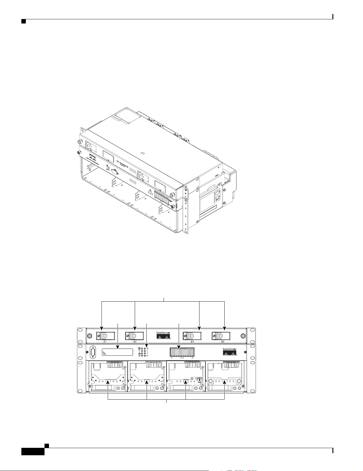
Figure 1-1 Cisco AC/DC Power System (with Optional 1RU DC Distribution Shelf)
Chapter 1 Introduction
124792
There are two system shelves, one of which has an LCD display on the front of the shelf.
Figure 1-2 shows a front view of the version of the system shelf with the LCD screen. The optional
1 RU DC distribution shelf is also shown.
Figure 1-2 Component Locations (Front View) on the System Shelf with LCD Screen
Circuit Breaker Positions
GMT
Fuse
Panel
50A MAX
(F1-10)
15A MAX FUSE
1RU
Distribution
Shelf
System
Shelf
10101
System
LCD
System
Status
Controls
1-2
159330
Rectifier
Positions
Cisco AC/DC Power System User Guide, R1.0
May 2006
Page 19
Chapter 1 Introduction
1.1.2 Rectifier Modules
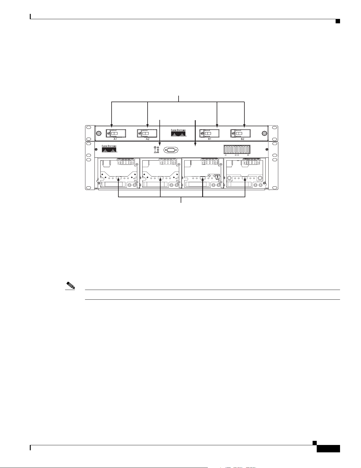
Figure 1-3 shows a front view of the version of the system shelf that does not have an LCD screen. The
optional 1 RU DC distribution shelf is also shown.
Figure 1-3 Component Locations (Front View) on the System Shelf without an LCD Screen
Circuit Breaker
Positions
1.1.2 Rectifier Modules
AC-to-DC power conversion is accomplished using two, three, or four hot-swappable
CSCO-PWR-RECT rectifiers, each with an output voltage of nominal -48 VDC. Figure 1-4 shows a
CSCO-PWR-RECT rectifier module.
System
Status
Rectifier
Positions
GMT Fuse
Panel
50A MAX
(F1-10)
15A MAX FUSE
1RU Distribution
Shelf
System Shelf
124778
May 2006
Note The output voltage range is set at the factory and is not user configurable.
Cisco AC/DC Power System User Guide, R1.0
1-3
Page 20
1.1.3 GMT Fuses
Chapter 1 Introduction
Figure 1-4 CSCO-PWR-RECT Rectifier Module
124776
1.1.3 GMT Fuses
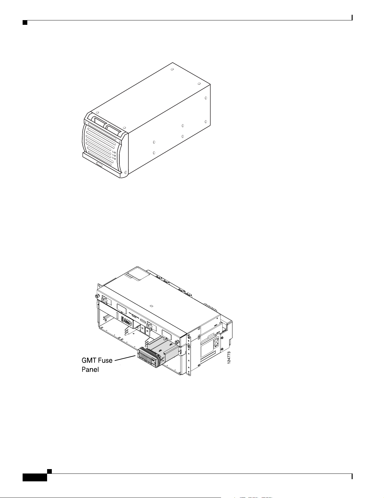
The system shelf is equipped with a 10-position GMT fuse panel. The GMT fuse panel has a 50A
maximum total capacity with a maximum fuse rating of up to 15A (for up to three positions). The fuses
are alarmed and are reported through the system controller.
Figure 1-5 GMT Fuse Panel
1.1.4 1 RU Distribution Shelf
The optional 1RU Distribution Shelf is installed in systems that contain more than 2 rectifiers and acts
as an additional protection point for system loads. The shelf has a rating of 96A and can be equipped
with up to four circuit breakers (up to a maximum rating of 30A each). The breakers are alarmed through
the system controller.
Cisco AC/DC Power System User Guide, R1.0
1-4
May 2006
Page 21
Chapter 1 Introduction
1.1.5 System Configurations
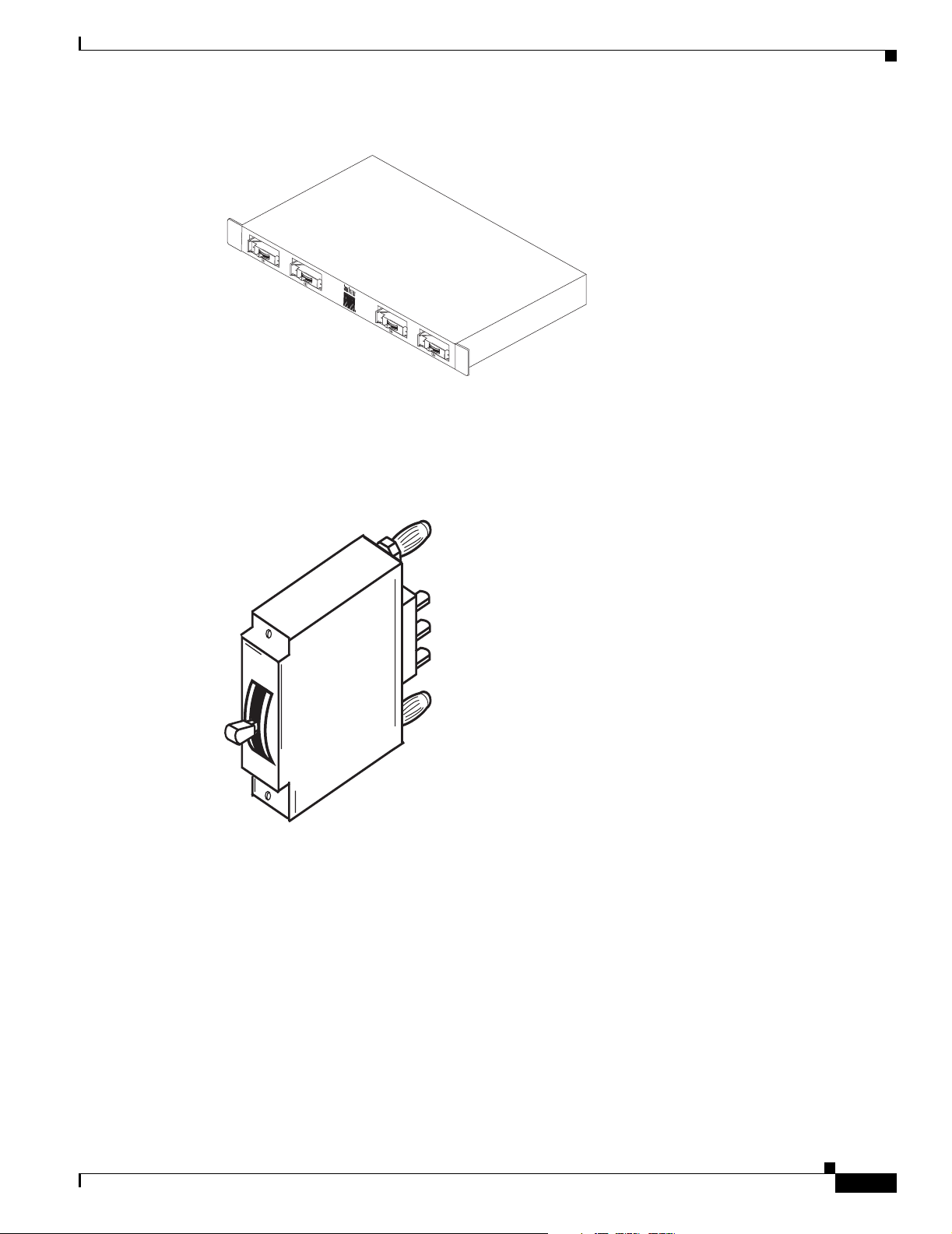
Figure 1-6 1 RU Distribution Shelf
124761
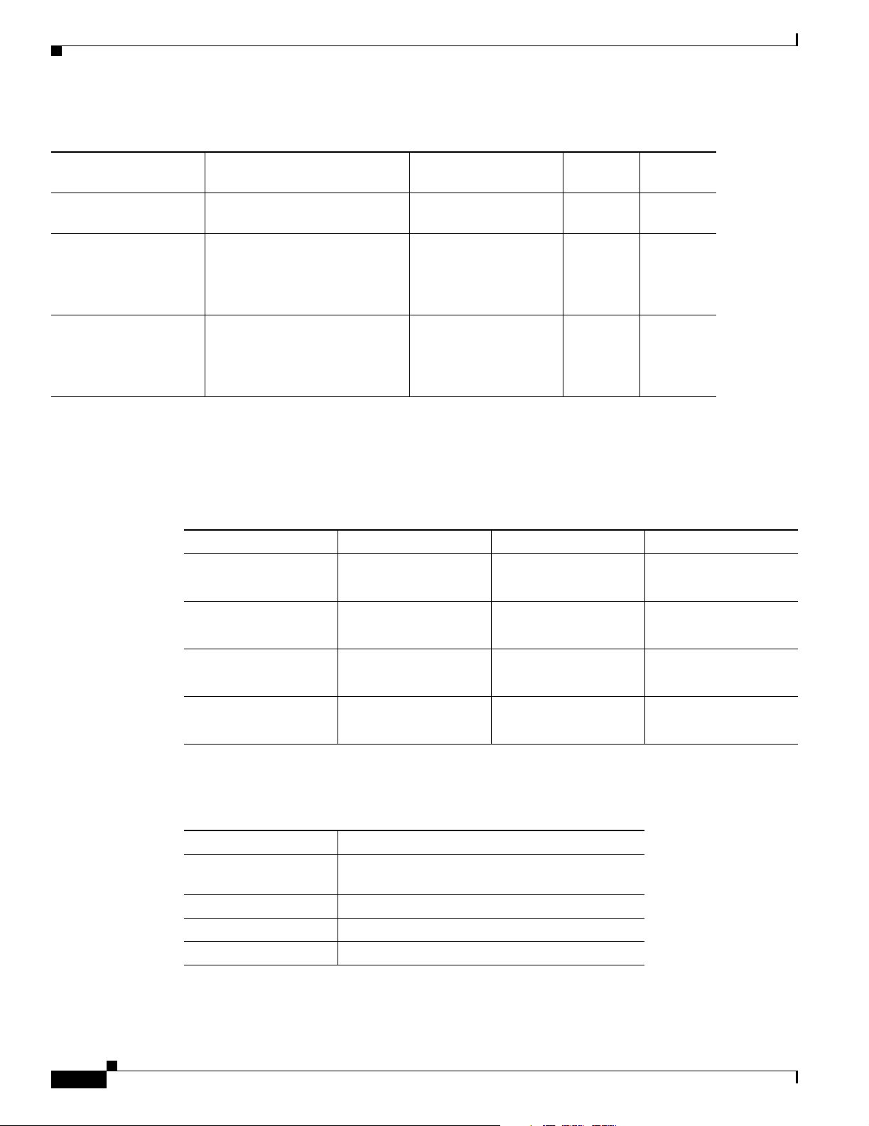
The 1RU External Distribution Shelf can accommodate up to four Series-Trip circuit breaker positions.
These breakers have “bullet type” connectors for quick connect and disconnect (Figure 1-7). Circuit
breakers can be rated from 5A-30A.
Figure 1-7 Circuit Breaker
1.1.5 System Configurations
Table 1 -1 lists the configurations available for the Cisco AC/DC Power System.
124767
May 2006
Cisco AC/DC Power System User Guide, R1.0
1-5
Page 22
1.1.6 General Specifications
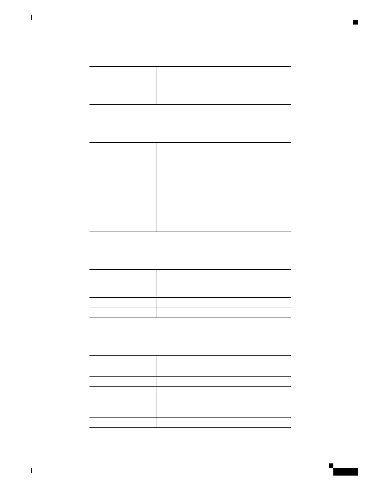
Table 1-1 System Configurations
Chapter 1 Introduction
Configuration Rectifiers Distribution
Small Systems 2 CSCO-PWR-RECT Modules 10-position GMT Fuse
Block
Medium Systems 3 CSCO-PWR-RECT Modules 10-position GMT Fuse
Block
4- position 1RU DC
Distribution Shelf
Large Systems 4 CSCO-PWR-RECT Modules 10-position GMT Fuse
Block
4- position 1RU DC
Distribution Shelf
1.1.6 General Specifications
Table 1 -2 provides cabling specifications for the Cisco AC/DC Power System.
Table 1-2 Cabling Specifications
From To Wire Gauge Ampacity
System Shelf 1U DC Distribution
Shelf
Circuit Breakers Load 10 - 8AWG
GMT Fuse Block Load 16 - 14AWG
AC Service Panel System Shelf 3 conductor 14AWG
4 x 6AWG (16mm²)
(intra-shelf cabling)
(6mm² - 10mm²)
(1.5mm² - 2.5mm²)
(2.5mm²) per AC input
Output at
220V AC
Output at
110V AC
32A 13.3A
64A 26.6A
96A 40A
96A (max)
30A (max)
15A (max)
9.1A x (4) inputs
<37A Total
1-6
Table 1 -3 provides electrical specifications for the Cisco AD/DC Power System.
Table 1-3 Electrical Specifications
Electrical Value
Input Voltage (A) 100-120VAC
(B) 200-250VAC
Input Frequency 44-66 Hz.
Transient Response +/- 4%, recovery time 2ms
Load Sharing +/- 5% of nominal current
Table 1 -4 provides protection specifications for the Cisco AC/DC Power System.
Cisco AC/DC Power System User Guide, R1.0
May 2006
Page 23
Chapter 1 Introduction
1.1.6 General Specifications
Table 1-4 Protection Specifications
Protection Description
Overcurrent (output) Short circuit and automatic current limiting
Overvoltage Selective shutdown of modules at excessive
output voltages
Table 1 -5 provides status and alarm specifications for the Cisco AC/DC Power System.
Table 1-5 Status and Alarm Specifications
Status & Alarms Description
Alarm Contacts Four form-C alarm contacts (Low Voltage, Mains
Error, Module Failure, Fuse/Circuit Breaker
Failure), maximum 60 VDC, rated at 1A
Status (Rectifier) Green LED indicates power is within acceptable
range
Yellow LED indicates current limit/thermal
protection
Red LED indicates overvoltage shutdown or
rectifier alarm
Table 1 -6 provides mechanical specifications of the Cisco AC/DC Power System.
Table 1-6 Mechanical Specifications
Mechanical Description
Shelf Dimensions
17.4 x 5.25 x 10.8in. (442 x 132.9 x274mm)
WxHxD
1RU Shelf WxHxD 17.1 x 1.69 x 9.175in. (434 x 43 x 233mm)
Mounting ETSI, 19in. (IEC and ANSI) or 23in.
Table 1 -7 provides environmental specifications for the Cisco AC/DC Power System.
Table 1-7 Environmental Specifications
Environment Description
Shock/Vibration (NEBS) Level 3, Class B Certification
Earthquake Zone 4 Compliant
Audible Noise <60 dBA
Ambient Temperature -40°C to 55°C
Storage Temperature -40°C to +85°C
Relative Humidity 10-90%, non-condensing
May 2006
Table 1 -8 provides compliance specifications for the Cisco AC/DC Power System.
Cisco AC/DC Power System User Guide, R1.0
1-7
Page 24
1.2 Safety Recommendations
1
Table 1-8 Compliance Specifications
Compliance Description
Radiated EMC EN 61000-6-2, EN 61000-6-3, FCC Part 15 Class B
EMC EN 61000-6-2, EN 61000-6-4
Safety CSA C22-2 No. 60950-1, UL 60950-1 and
IEC60950-1/EN60950-1
ESD Immunity EN61000-4-2
RF Immunity EN61000-4-3
Surge Immunity IEC/EN61000-4-5
Fast Transient/Burst
IEC/EN61000-4-4
Immunity
Immunity EN61000-4-2
ETSI 300-386-TC
Chapter 1 Introduction
1.2 Safety Recommendations
Any device that uses electricity requires proper guidelines to ensure safety.
Warning
Warning
Only trained and qualified personnel should be allowed to install, replace, or service this equipment.
Statement 1030
This unit is intended for installation in restricted access areas. A restricted access area can be
accessed only through the use of a special tool, lock and key, or other means of security.
Statement 1017
• The Cisco AC/DC Power System should only be installed or serviced by qualified personnel.
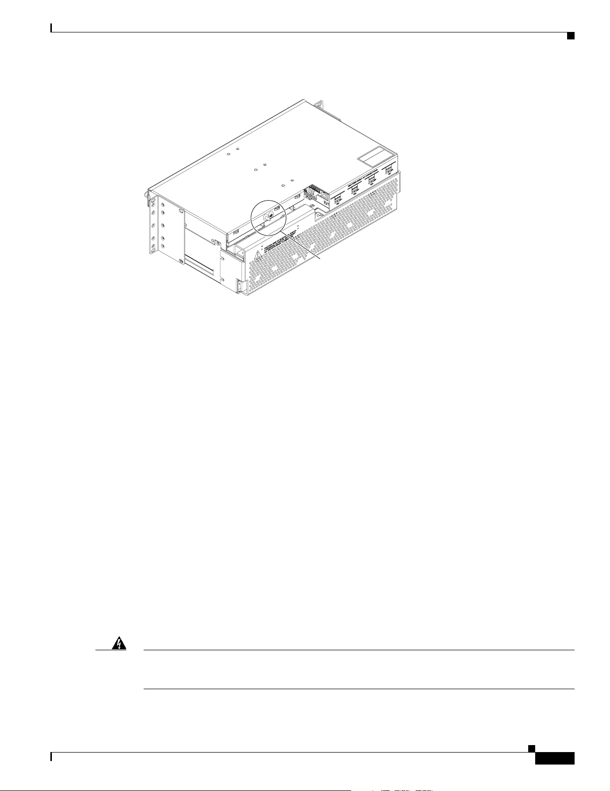
• An ESD wrist strap is included to protect sensitive electronics and should be connected to a metal
surface to act as a ground. This ensures that all components have the same charge. An ESD wrist
strap should be used when working with internal components that are installed in the shelf. The wrist
strap connects at the rear of the system shelf as shown in Figure 1-8. If rear access is not available,
the ESD wrist strap can be connected to the shelf mounting ears or the controller faceplate thumbscrews.
1-8
Cisco AC/DC Power System User Guide, R1.0
May 2006
Page 25
Chapter 1 Introduction
1.2.1 Installation Warning
Figure 1-8 ESD Wrist Strap Connection Point
124769
ESD Connection
Point
•
Keep the system area clear and dust-free during and after the installation.
• Always check for possible hazards before beginning work.
• This equipment is designed to permit the connection of a grounded conductor for the DC supply
circuit at the equipment.
1.2.1 Installation Warning
The following safety guidelines should be observed when transporting or moving the system to the
install location:
• Before moving the Cisco AC/DC Power System, read the system specifications sheet to determine
if the site meets all the size, environmental, and power requirements.
• The Cisco AC/DC Power System should be properly mounted to the equipment rack.
The Cisco AC/DC Power System is designed for installation in restricted access locations. A restricted
access location is defined as an equipment location where both of the following conditions apply:
• Access can only be gained by service persons or users who understand the restrictions applied to the
location and any precautions that must be taken.
• Access to the system is obtained through the use of a tool or lock and key, or other means of security,
and is controlled by the authority responsible for the location.
1.2.2 Operating Temperature Warnings
Warning
May 2006
To prevent the system from overheating, do not operate it in an area that exceeds the maximum
recommended ambient temperature of: 55° Celsius.
Statement 1047
Cisco AC/DC Power System User Guide, R1.0
1-9
Page 26
1.2.3 Electrical Safety Warnings
Chapter 1 Introduction
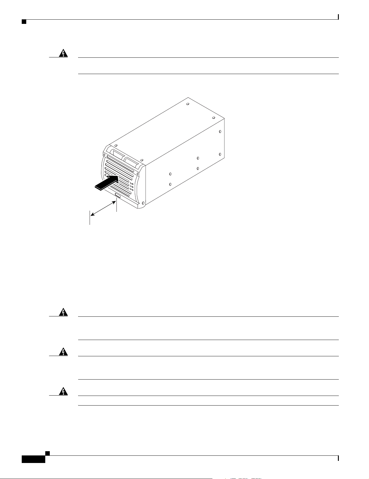
Warning
To prevent airflow restriction, allow clearance around the ventilation openings to be at least 2.0
inches (50.8 mm).
Figure 1-9 Two-Inch Clearance Around Front Ventilation Opening
131187
Airflow
2 in.
50.8 mm
This power system is intended for use in a restricted location where the ambient temperature falls
between -40° and +55° Celsius. It is not recommended to continually operate the power system in an
area that exceeds the maximum recommended operating temperature. To prevent the Cisco AC/DC
Power System from overheating, the rectifier automatically shuts down when a thermal alarm is tripped.
1.2.3 Electrical Safety Warnings
The following are electrical safety recommendations for working near the Cisco AC/DC Power System:
Warning
Warning
Warning
Before working on equipment that is connected to power lines, remove jewelry (including rings,
necklaces, and watches). Metal objects will heat up when connected to power and ground and can
cause serious burns or weld the metal object to the terminals.
This equipment must be grounded. Never defeat the ground conductor or operate the equipment in the
absence of a suitably installed ground conductor. Contact the appropriate electrical inspection
authority or an electrician if you are uncertain that suitable grounding is available.
Installation of the equipment must comply with local and national electrical codes.
Statement 43
Statement 1024
Statement 1074
1-10
Cisco AC/DC Power System User Guide, R1.0
May 2006
Page 27
Chapter 1 Introduction
1.2.3 Electrical Safety Warnings
Warning
Warning
Warning
Before working on a chassis or working near power supplies, unplug the power cord on AC units;
disconnect the power at the circuit breaker on DC units.
Statement 12
This product requires short-circuit (overcurrent) protection, to be provided as part of the building
installation. Install only in accordance with national and local wiring regulations.
Installation of the equipment must comply with local and national electrical codes.
• Before connecting the AC input source to the power system, always verify frequency and voltage.
• When making AC connections, all AC power and DC load distribution breakers should be in the
Statement 1045
Statement 1074
OFF position.
• Ensure that the proper size circuit protection is being used.
May 2006
Cisco AC/DC Power System User Guide, R1.0
1-11
Page 28

1.2.3 Electrical Safety Warnings
Chapter 1 Introduction
1-12
Cisco AC/DC Power System User Guide, R1.0
May 2006
Page 29
System Installation
This provides step-by-step instructions for installing a Cisco AC/DC Power System. If you are installing
a new system, begin with the “2.1 Pre-Installation” section on page 2-1. If you are upgrading an existing
system, go to the “2.6 System Upgrades” section on page 2-28 for instructions.
2.1 Pre-Installation
The following information should be reviewed before attempting to install the Cisco AC/DC Power
System.This section includes shelf markings, tools, equipment, and an installation checklist. Refer to the
“1.2 Safety Recommendations” section on page 1-8 before beginning installation.
Note Each system installation is unique, so please review specific site requirements and system configurations
before installing the system.
CHA PTER
2
2.1.1 Ground Symbol
Figure 2-1 shows the ground symbol located on the Cisco AC/DC Power System.
Figure 2-1 Ground Symbol
2.1.2 Tools Required
The following tools and parts are required for safe installation of the Cisco AC/DC Power System:
• Digital multimeter
124774
May 2006
Cisco AC/DC Power System User Guide, R1.0
2-1
Page 30

2.1.3 Installation and Commissioning Checklist
• Insulated Phillips and flathead screwdriver sets
• Insulated wire & cable strippers/crimpers (for ground lug, DC cable, alarm, and GMT cable
installations)
• 8mm socket or wrench for ground cable installation
1
2.1.3 Installation and Commissioning Checklist
• AC/DC system shelf mounted securely in rack
• 1 RU Distribution Shelf mounted securely in rack directly above the system shelf (if applicable)
• AC and DC cabling meets local and national electrical code specifications
• Installation in ETSI racks allows for front-to-back ventilation and the use of a ventilated door and
cabinet top
• System alarm cabling is installed and secure
• Power cables are secure and installed correctly
Chapter 2 System Installation
• Rectifiers are installed and seated correctly in the system shelf
• The controller and 1 RU Distribution faceplates are installed and secure (if applicable)
• System shelf rear cover is installed and secured
• System powers up and all red LEDs are extinguished after a few minutes
2.1.4 Installation Materials
Table 2 -1 and Table 2-2 list the Cisco supplied installation materials that ship with the Cisco AC/DC
Power System. Tab le 2-3 lists materials that will need to be furnished at the install location.
Table 2-1 Supplied Materials for the System Shelf
Description Qty Use
M6 0x20mm screw (thread forming) 6 Shelf mounting screws (ETSI racks/cabinets)
12-24 x1/2” screw (thread forming) 6 Shelf mounting screws (ANSI, IEC racks/
M6 cage nut 6 Shelf mounting nut (ETSI racks/cabinets)
Mounting bracket 600mm ETSI rack 2 Ear mounts (ETSI racks/cabinets)
2A GMT fuse 2 GMT fuse panel
5A GMT fuse 2 GMT fuse panel
10A GMT fuse 2 GMT fuse panel
15A GMT fuse 2 GMT fuse panel
Standard AC plug 4 AC plugs that meet local requirements
Cable ties 12 Securing cables
ESD wrist strap 1 ESD protection
cabinets)
2-2
Cisco AC/DC Power System User Guide, R1.0
May 2006
Page 31

Chapter 2 System Installation
Table 2-1 Supplied Materials for the System Shelf (continued)
Description Qty Use
Quick Installation Guide 1 Installation instructions
System documentation 1 Installation, provisioning, and troubleshooting
Table 2-2 Supplied Materials for the 1 RU Distribution Shelf
Description Qty Use
M6 0x20mm screw (thread forming) 4 Shelf mounting screws (ETSI racks/cabinets)
12-24 x 1/2” screw (thread forming) 4 Shelf mounting screws (ANSI, IEC racks/
M6 cage nut 4 Shelf mounting nut (ETSI racks/cabinets)
Mounting bracket 600mm ETSI rack 2 Ear mounts (ETSI racks/cabinets)
Quick disconnect circuit breakers 2 1RU Distribution Shelf
Cable ties 4 Securing cables
ESD wrist strap 1 ESD protection
Quick Installation Guide 1 Installation instructions
2.2 Install AC/DC Power System Components
cabinets)
Table 2-3 Non-Supplied Materials
Description Qty Use
6AWG (16mm²) grounding cable 1 system shelf grounding
6AWG (16mm²) grounding cable 1 1RU Distribution grounding (if applicable)
10 to 8 AWG (6 to 10mm²) cables <8 DC load breaker connections (-48V and return)
22 AWG (0.34mm²) cables n/a 2A GMT fuse cabling
18 AWG (0.75mm²) cables n/a 5A GMT fuse cabling
14 AWG (2.5mm²) cables n/a 10/15A GMT fuse cabling
26 to 22AWG (0.14mm²- 0.34mm²)
cables
UL Listed double-hole lug 1/4in and
5/8in. center-to-center (lug part #
Panduit LCD6 -14A-L or equivalent)
4 Alarm cabling
2 Ground cable installation
2.2 Install AC/DC Power System Components
The following sections contain instructions for installing components. Figure 2-2 shows a drawing of the
Cisco AC/DC Power System without rectifiers.
May 2006
Cisco AC/DC Power System User Guide, R1.0
2-3
Page 32

2.2.1 Install the System Shelf
Figure 2-2 Cisco AC/DC Power System Front View
Chapter 2 System Installation
System Shelf
2.2.1 Install the System Shelf
Warning
To prevent bodily injury when mounting or servicing this unit in a rack, you must take special
precautions to ensure that the system remains stable. The following guidelines are provided to
ensure your safety:
• This unit should be mounted at the bottom of the rack if it is the only unit in the rack.
• When mounting this unit in a partially filled rack, load the rack from the bottom to the top with the heaviest
component at the bottom of the rack.
• If the rack is provided with stabilizing devices, install the stabilizers before mounting or servicing the unit in
the rack.
Statement 1006
The system shelf should be installed first, followed by the 1 RU Distribution Shelf (if this option is
included as part of the installation).
Rectifier
Positions
124778
2-4
Step 1 Determine if the correct ear mounts are installed on the system shelf. Ear mounts are shipped mounted
on the shelf and support 19in. and 23in. IEC and ANSI standards (for 23in. shelves, ears should be
removed, reversed and reinstalled). Two additional plates are also included to accommodate ETSI racks
(Figure 2-3). To install ETSI mounting ears, remove existing ears and attach ETSI mounting ears using
included hardware.
Cisco AC/DC Power System User Guide, R1.0
May 2006
Page 33

Chapter 2 System Installation
Figure 2-3 ETSI Shelf Ear Mounts (system shelf and 1RU Distribution Shelf)
2.2.1 Install the System Shelf
124770
Step 2
Move the system shelf to the desired rack/cabinet slot (allowing 1RU above the shelf if a 1 RU
Distribution shelf will be installed).
Step 3 Secure the system shelf to the rack using the six included mounting screws (Figure 2-4).
Figure 2-4 Installing the System Shelf
May 2006
Step 4
124779
Continue with the “2.2.2 Install the 1 RU Distribution Shelf” procedure on page 2-6 if applicable. If this
system has no external distribution, place the 4 power connectors and alarm cables on the top of the
system shelf to aid in future 1 RU Distribution Shelf installation (Figure 2-5) and continue with
the“2.2.3 Install the Ground Cable” section on page 2-9.
Cisco AC/DC Power System User Guide, R1.0
2-5
Page 34

2.2.2 Install the 1 RU Distribution Shelf
Figure 2-5 1 RU Distribution Cable Dressing
Chapter 2 System Installation
124790
2.2.2 Install the 1 RU Distribution Shelf
Systems equipped with an optional 1 RU Distribution Shelf require power connections from the system
shelf to the 1 RU Distribution Shelf using four cables terminated with Anderson power pole connectors.
These cable connectors are pre-wired to the system shelf and should be connected to the 1 RU
Distribution Shelf during installation.
Note In pre-installed system shelves, the DC cabling should be located at the top of the system shelf. Cable
labels are provided (-48V and Return) for ease of installation.
In addition, the distribution alarm connection is made via a pre-wired 10 pin Molex™ connector from
the system shelf and should be connected to the 1 RU Distribution Shelf at the indicated connection
point.
Step 1 Determine if the correct ear mounts are installed on the system shelf. Ear mounts are shipped mounted
on the shelf and support 19in. and 23in. IEC and ANSI standards (for 23in. shelves, ears should be
removed, reversed, and reinstalled). Two additional plates are also included to accommodate ETSI racks
(Figure 2-3 on page 2-5). To install ETSI mounting ears, remove existing ears and attach ETSI mounting
ears using included hardware.
Step 2 Make sure that all circuit breakers are in the OFF position (see Figure 2-16 on page 2-19).
Step 3 Move the 1 RU Distribution Shelf to the desired rack slot (directly above the system shelf).
Step 4 Secure the 1 RU Distribution Shelf to the rack using the four included mounting screws (Figure 2-6). See
for more information.
2-6
Cisco AC/DC Power System User Guide, R1.0
May 2006
Page 35

Chapter 2 System Installation
Figure 2-6 1 RU Distribution Shelf Installation
2.2.2 Install the 1 RU Distribution Shelf
124759
2.2.2.1 Install the Communications Cabling (Optional)
If the power system is equipped with the 1 RU Distribution Shelf, follow the instructions below. For
power systems without the 1 RU Distribution Shelf, skip this procedure and go to the “2.2.3 Install the
Ground Cable” procedure on page 2-9.
Intra-system shelf communication is accomplished using a 10 pin Molex™ connector originating from
the system shelf and connecting to the 1 RU Distribution Shelf. Use the following instructions to install
the communications cabling:
Step 1 Locate the distribution alarm cable at the rear of the system shelf.
Step 2 This cable is a prewired 10 pin Molex™ connector and is installed into the 1RU at the indicated location
(Figure 2-7).
Note The Molex™ alarm connector is keyed and can only be inserted one way. If the connector does
not insert easily into the mount, make certain that the connector is being inserted with the key
side up.
May 2006
Cisco AC/DC Power System User Guide, R1.0
2-7
Page 36

2.2.2 Install the 1 RU Distribution Shelf
Figure 2-7 1 RU Distribution Shelf Alarm Cabling
Chapter 2 System Installation
2.2.2.2 Install the DC Power Cabling (Optional)
If the system is equipped with the 1 RU Distribution Shelf, follow the instructions below. For systems
without the 1 RU Distribution Shelf, skip this procedure and go to the “2.2.3 Install the Ground Cable”
procedure on page 2-9.
Step 1 Locate the four 6AWG (16mm²) power cables provided at the rear of the system shelf (on top of the
system shelf in preinstalled systems). These are terminated with Anderson Powerpole™ Connectors (to
install these connectors, remove the heat shrink from the ends of the connector).
Step 2 Connect to the appropriate connection points on the 1RU Distribution Shelf labeled load (-48V) and
return (RETURN) (Figure 2-8).
Note Anderson Powerpole™ Connectors are keyed and can only be inserted one way. If the connector
does not insert easily into the mount, make certain that the connector is being inserted with the
key side up.
124758
2-8
Cisco AC/DC Power System User Guide, R1.0
May 2006
Page 37

Chapter 2 System Installation
Figure 2-8 Installing 1 RU DC Cabling
2.2.3 Install the Ground Cable
Return
Load
2.2.3 Install the Ground Cable
Warning
This equipment must be grounded. Never defeat the ground conductor or operate the equipment in the
absence of a suitably installed ground conductor. Contact the appropriate electrical inspection
authority or an electrician if you are uncertain that suitable grounding is available.
The equipment rack/cabinet, system, and optional distribution shelf need to be properly grounded to
ensure the safe and efficient operation of the Cisco AC/DC Power System. Refer to NEC, CEC, ANSI
T1-333, ETSI 300-386-TC, and local codes for guidelines on bonding telecom DC power equipment to
building ground.
The system shelf should be connected to the rack/cabinet frame by a UL-listed 6 AWG (16mm²) wire
with an insulation rating of at least 75° Celsius. Two #10 studs are provided at the rear of the shelf. The
connection at the shelf end is made using a UL-listed double-hole lug 1/4in and 5/8in. center-to-center
(lug part # Panduit LCD6-14A-L or equivalent).
The optional 1 RU Distribution Shelf should be bonded to the frame by a UL-listed 6 AWG (16mm²)
wire with an insulation rating of at least 75° Celsius. Two #10 studs are provided at the rear of the shelf
for this purpose. The connection at the shelf end is made using a UL-listed double-hole lug 1/4in. and
5/8in. center-to-center (lug part # Panduit LCD6-14A-L or equivalent).
124783
Statement 1024
May 2006
Cisco AC/DC Power System User Guide, R1.0
2-9
Page 38

2.2.3 Install the Ground Cable
2.2.3.1 Install the Cabinet/Rack Ground
The equipment rack should be bonded to the building principal ground busbar. Refer to the NEC, CEC,
ANSI T1-333, ETSI 300-386-TC, and local codes for guidelines on bonding telecom DC power
equipment to the building ground.
2.2.3.2 Install the System Shelf Ground
Step 1 Loosen the cover from the rear of the system shelf by loosening the four screws (Figure 2-9).
Figure 2-9 Removing the System Shelf Rear Cover
Chapter 2 System Installation
124788
Step 2 Pull out from the bottom and lift up to remove.
Step 3 Locate the #10 studs at the rear of the system shelf (Figure 2-10).
Step 4 Using a UL-listed 6 AWG (16mm²) wire with an insulation rated to at least 75°C, connect the shelf to
the appropriate cabinet connection point. The connection at the shelf end is made using a UL-listed
double-hole lug 1/4in and 5/8in. center-to-center (lug part # Panduit LCD6-14A-L or equivalent)
(Figure 2-10).
2-10
Cisco AC/DC Power System User Guide, R1.0
May 2006
Page 39

Chapter 2 System Installation
Figure 2-10 Installing the System Shelf Ground
2.2.3 Install the Ground Cable
Step 5
Determine if the system is equipped with the optional 1 RU Distribution Shelf; if so, continue with the
“2.2.3.3 Install the 1 RU Distribution Shelf Ground” section on page 2-11. If not continue with the
“2.3 Install AC Power Cables” section on page 2-12.
2.2.3.3 Install the 1 RU Distribution Shelf Ground
Step 1 Locate the #10 studs at the rear of the 1 RU Distribution Shelf.
Step 2 Using a UL-listed 6 AWG (16mm²) wire with an insulation rating of at least 75° C, connect the 1 RU
Distribution Shelf to the appropriate cabinet connection point.
Step 3 The connection at the shelf end is made using a UL-listed double-hole lug 1/4in and 5/8in.
center-to-center (lug part # Panduit LCD6-14A-L or equivalent) (Figure 2-11).
Step 4 To accommodate future upgrades, leave a service loop (1.5ft [60cm]) at the side of the shelf.
124791
May 2006
Cisco AC/DC Power System User Guide, R1.0
2-11
Page 40

2.3 Install AC Power Cables
Figure 2-11 Installing the 1 RU Distribution Shelf Ground
Chapter 2 System Installation
2.3 Install AC Power Cables
Each rectifier in the system shelf is individually powered through a 110/230 V AC single phase 15A
circuit and draws a maximum of 9.1A.
Each rectifier position in the shelf can be powered by either:
• 208/220/240V AC split phase
• 230V single phase
• 110V single phase
• Max current per position (9.1A)
Note Rectifier output capacity at 110 VAC is reduced to less than half of the maximum output.
• Locate the power shut-off switch for the installation area
• Install the system using the following electrical codes:
–
United States National Electrical Code (NEC)
–
Canadian Electrical Code (CEC)
124763
2-12
Cisco AC/DC Power System User Guide, R1.0
May 2006
Page 41

Chapter 2 System Installation
–
International Electromechanical Commission (IEC)
–
Any local or site specific codes
–
EN60950
2.3 Install AC Power Cables
Warning
Installation of the equipment must comply with local and national electrical codes.
• Never install damaged or malfunctioning equipment.
Statement 1074
To install AC power to the Cisco AC/DC Power System:
Step 1 Ensure that input circuit breakers or fuses are off or removed and the cable is not connected to the outlet.
Step 2 To aid in future expansion, all AC cable positions should be connected to the rear of the shelf during
installation.
Step 3 The system shelf is supplied with four AC cables. Each AC cable provides power to individual rectifier
positions. The cable is terminated to allow for local plug requirements.
Note A 15A circuit (for both 110 and 208V AC) should be used based on maximum AC input per
rectifier (9.1A).
Step 4 The rear system shelf cover should already be removed, if not, remove it.
Step 5 Locate the cables at the rear of the system shelf.
Step 6 Attach the ferrule end of the cables (Ground (G), L1, and L2 (neutral) to the system shelf AC receptacle
by inserting (the ferrule will only fit in one direction) and tightening with a flat screwdriver
(Figure 2-12).
May 2006
Cisco AC/DC Power System User Guide, R1.0
2-13
Page 42

2.3 Install AC Power Cables
Figure 2-12 Installing the AC Cable Shelf
Chapter 2 System Installation
124784
Step 7 After attaching the AC cables, route the cables at the rear of the shelf using the supplied tie-offs to secure
the cables and exit at the sides of the shelf (Figure 2-13).
2-14
Cisco AC/DC Power System User Guide, R1.0
May 2006
Page 43

Chapter 2 System Installation
Figure 2-13 Routing AC Cables
2.3 Install AC Power Cables
May 2006
Step 8
AC cabling is routed through either side of the system shelf and secured using tie off points.
Step 9 AC cabling should be tied off inside the cabinet/rack.
Step 10 Repeat for all AC cables.
Step 11 Connect the terminated AC plug to the AC receptacle at the install location.
Note A separate AC receptacle is required for each AC cable, and each receptacle should be on its own
circuit breaker to maximize protection against AC circuit breaker failure.
Cisco AC/DC Power System User Guide, R1.0
124793
2-15
Page 44

2.3.1 Install the Rectifiers
Table 2-4 Individual AC Feed Specifications
Chapter 2 System Installation
Shelf Size
19 inch 1 15A 14 AWG (2.5mm²)
19 inch 2 15A 14 AWG (2.5mm²)
19 inch 3 15A 14 AWG (2.5mm²)
19 inch 4 15A 14 AWG (2.5mm²)
2.3.1 Install the Rectifiers
To install the rectifiers in the Cisco AC/DC Power System:
Step 1 Locate the first (left-most when viewed from the front) rectifier install location.
Step 2 Make sure that the rectifier handle is in the OPEN position (handle pulled away from the rectifier body).
Step 3 Place the module in front of the correct mounting slot on the shelf with the handle facing out
(Figure 2-14 #1).
Rectifier
Positions
AC Input (Fuse or
Breaker) 110/208 VAC
Single Phase
Minimum AC Wire
Gauge
UL Style SOOW
3 conductor
3 conductor
3 conductor
3 conductor
2-16
Step 4 Slide the module until it contacts the interface connection at the rear of the shelf.
Step 5 Fully insert the rectifier by pushing the module handle towards the shelf; the handle will rise up and lock
the module into place (Figure 2-14 #2).
Cisco AC/DC Power System User Guide, R1.0
May 2006
Page 45

Chapter 2 System Installation
Figure 2-14 Installing a Rectifier
2.3.1 Install the Rectifiers
1
2
124786
Step 6
Step 7 Repeat this procedure for any additional modules (two total for small systems, three for medium
Tighten the handle-mounted common screws into the rectifier to ensure a firm connection (Figure 2-14
#2).
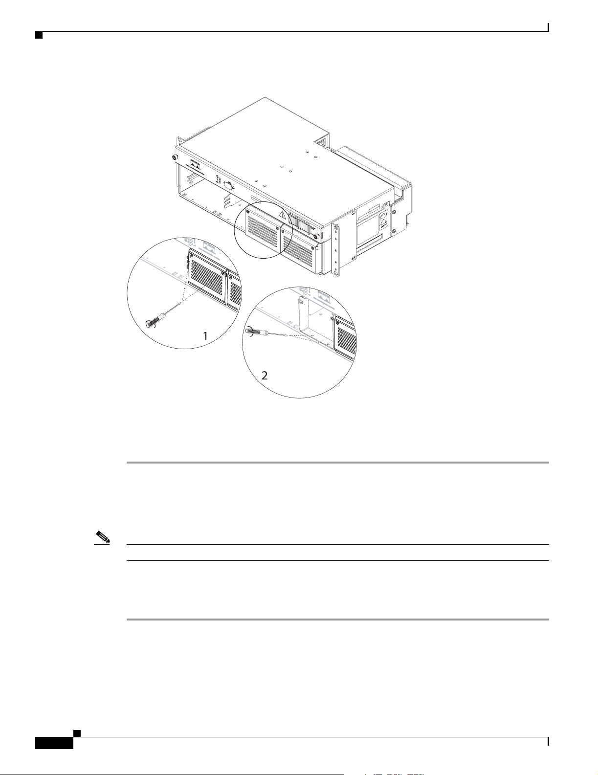
systems, and four for large systems. Some systems may require removing blank rectifier faceplates. To
do this, remove the two Phillips screws from the blank rectifier faceplate (Figure 2-15 #1). Remove the
blank rectifier faceplate mounting bracket by removing the two Phillips screws (Figure 2-15 #2).
May 2006
Cisco AC/DC Power System User Guide, R1.0
2-17
Page 46
2.4 Install Circuit Breakers
Figure 2-15 Removing a Rectifier Blank Faceplate
Chapter 2 System Installation
Step 8
Install additional rectifiers using the instructions in Steps 2 through 5.
For more information on installing rectifiers in a powered system, see the “4.2.2.2 Add Modules”
section on page 4-2.
2.4 Install Circuit Breakers
Note This procedure is optional for large systems.
Large systems equipped with the 1 RU Distribution Shelf require the installation of circuit breakers to
ensure proper system protection (the 1 RU Distribution Shelf is shipped with circuit breakers installed
for use in medium systems). To install circuit breakers in a large system:
Step 1 Make certain all breakers to be installed are in the OFF position (Figure 2-16).
124789
2-18
Cisco AC/DC Power System User Guide, R1.0
May 2006
Page 47

Chapter 2 System Installation
Figure 2-16 Circuit Breaker On/Off Positions
Hood
2.4 Install Circuit Breakers
Common
Not Used
Normally Closed
Step 2
On
124766
Off
Remove the 1 RU Distribution Shelf faceplate by loosening the two thumbscrews on the shelf faceplate
(Figure 2-17).
Figure 2-17 Removing the 1 RU Distribution Shelf Faceplate
124762
May 2006
Step 3 Locate the circuit breaker installation locations inside the 1 RU Distribution Shelf (positions A1, A2,
B1, and B2) (see Table 2-5 on page 2-20). Circuit breakers should be installed with the protective hood
(covering the ON position) on the left side of the shelf (Figure 2-16) to allow the 1 RU Distribution Shelf
faceplate to be correctly installed.
Step 4 Attach the circuit breaker alarm cables to the rear of the circuit breaker; the alarm cables are labeled C
(Common) and NC (Normally Closed) and are attached to the positions shown in Figure 2-16.
Cisco AC/DC Power System User Guide, R1.0
2-19
Page 48

2.4 Install Circuit Breakers
Table 2-5 Circuit Breaker Positions
System Size A1 A2 B1 B2
Small n/a n/a n/a n/a
Medium X
Large XXX X
1. Future Upgrade
2. Future Upgrade
Step 5 Gently glide the breaker so that the quick disconnect plugs are aligned with the mounting holes
(Figure 2-18).
Figure 2-18 Installing a Circuit Breaker
Chapter 2 System Installation
1
X
2
2-20
Common
Step 6
Push the breaker until the quick disconnect plugs are firmly seated in the mounting holes.
Step 7 Repeat for additional breaker.
Cisco AC/DC Power System User Guide, R1.0
Normally
Closed
124756
May 2006
Page 49

Chapter 2 System Installation
Step 8 Replace the 1 RU Distribution Shelf faceplate and tighten the thumbscrews.
2.4.1 Install the Alarm Cable
The following explains how to install alarm communication cabling to the Cisco AC/DC Power System
Controller.
2.4.1 Install the Alarm Cable
Warning
Note Alarm cables run from the rear right of the shelf through the power shelf (Figure 2-20) to the front alarm
Connect the unit only to DC power source that complies with the safety extra-low voltage (SELV)
requirements in IEC 60950 based safety standards.
Statement 1033
interface board connectors; remove the controller faceplate and slide the controller tray forward to
access the alarm interface board.
To install alarm cabling to the Cisco AC/DC Power System:
Step 1 Remove the system shelf faceplate (by loosening the two front thumbscrews) to access the controller
sliding drawer (Figure 2-19).
May 2006
Cisco AC/DC Power System User Guide, R1.0
2-21
Page 50

2.4.1 Install the Alarm Cable
Figure 2-19 Removing the Controller Faceplate
Chapter 2 System Installation
124765
Step 2 Slide the drawer out and away from the system shelf to access the alarm interface board.
Step 3 The terminal block may be removed to make alarm cable connections (Figure 2-20).
2-22
Cisco AC/DC Power System User Guide, R1.0
May 2006
Page 51

Chapter 2 System Installation
Figure 2-20 Installing an Alarm Cable
2.4.1 Install the Alarm Cable
Service Loop
Tie-off Points
124795
Step 4
Alarm contacts labeled 1 through 4, NO, C, and NC refer to the OFF state of the power system and
alarmed condition (Table 2 -6).
Table 2-6 Alarm and Jumper Designations
Jumper
(System with
LCD)
Jumper
(System
without LCD) Alarm Designation 1234
J16 (1-3) J16 (1-3) Low Voltage X
J15 (1-3) J15 (1-3) Mains Error X
J14 (1-3) J14 (1-3) Module Failure X
J14 (4-6) J13 (1-3) Fuse/Circuit Breaker
X
Failure
Note Either NO or NC can be used for alarming. Figure 2-20 depicts the NC connection in the 1 and
3 positions on the connectors.
Step 5 The terminal blocks (green) will accept 26AWG (0.14mm²) to 22AWG (0.34mm²) cables. Remove the
terminal block (Figure 2-20 #1).
Step 6 Insert the stripped alarm cables and tighten using a flat screwdriver (Figure 2-20 #2). Refer to
Figure 2-21 (Version 2 of the controller) and Figure 3-4 on page 3-5 (Version 1 of the controller) for
information on alarm connection locations.
May 2006
Cisco AC/DC Power System User Guide, R1.0
2-23
Page 52

2.5 Install Load-and-Return Connections
Figure 2-21 Alarm Board Connection Points
Chapter 2 System Installation
Step 7 Reinsert the terminal block (Figure 2-20 #3).
Step 8 Alarm cables run from the rear of the system shelf (leaving enough of a service loop to allow the drawer
to slide out) through the access window (between the controller drawer and the GMT drawer area)
(Figure 2-20).
Step 9 Secure the alarm cables using the provided strain relief tie-offs to aid in cable management.
2.5 Install Load-and-Return Connections
The following section contains information on installing different distribution options available for the
power system. Tabl e 2-7 provides a list of recommended wire gauges for both the GMT fuse panel and
the 1 RU Distribution Shelf.
Table 2-7 Recommended Wire Sizes
Wire Gauge Stranded Applications
10 to 8 AWG
(6mm² to 10mm²)
22 AWG (0.34mm²) 2A GMT Fuses
18 AWG (0.75mm²) 5A GMT Fuses
Breaker Load
(up to 30A)
124764
2-24
Cisco AC/DC Power System User Guide, R1.0
May 2006
Page 53

Chapter 2 System Installation
Table 2-7 Recommended Wire Sizes (continued)
Wire Gauge Stranded Applications
14 AWG (2.5mm²) 10A GMT Fuses
14 AWG (2.5mm²) 15A GMT Fuses
2.5.1 Install GMT Fuse Connections
Load connections to the GMT fuse panel are made using spring loaded terminals that do not require the
use of connection lugs.
Step 1 Locate the GMT fuse connections by removing the controller faceplate (Figure 2-19) and sliding the
GMT drawer out (Figure 2-22).
Figure 2-22 GMT Drawer
2.5.1 Install GMT Fuse Connections
May 2006
Step 2
Route the GMT load-and-return cabling from the rear of the system shelf (leaving enough of a service
loop to allow the drawer to slide out) through the fuse panel channel and secure using the supplied
tie-downs.
Step 3 Connect the wires to the appropriate terminal by using a flat screwdriver to open the terminal
(Figure 2-23) and inserting the appropriate cable into the spring-loaded terminals. Terminals correspond
to fuses: Side A (1-5) and Side B (1-5) from left to right (viewed from the front of the system).
Cisco AC/DC Power System User Guide, R1.0
2-25
Page 54

2.5.2 Install 1 RU Distribution Shelf Load Connections
Figure 2-23 Installing GMT Cabling
Chapter 2 System Installation
Step 4
Step 5 Install fuses by sliding them into the appropriate slot (Figure 2-24).
Connect cables to equipment that requires the supplied DC Power per that equipment’s specifications.
Figure 2-24 Installing Fuses
Blank
15A Fuse
Blank
124771
Note An empty space should be left on each side of any 15A GMT fuse used for thermal considerations.
2.5.2 Install 1 RU Distribution Shelf Load Connections
The following section is for systems that use the 1 RU Distribution Shelf. For systems without the 1 RU
Distribution Shelf, go to Chapter 4, “System Operation.”
Cisco AC/DC Power System User Guide, R1.0
2-26
May 2006
Page 55

Chapter 2 System Installation
Step 1 Select the wire gauge for the application. See Table 2-7 on page 2-24 for wiring information.
Step 2 Locate the load-and-return connections at the rear of the 1 RU Distribution Shelf (Figure 2-25).
Step 3 Remove the Phoenix Contact PC6™ connectors from the 1 RU Distribution Shelf by loosening the flat
screws and pulling the connectors away from the 1 RU Distribution Shelf (Figure 2-25 #1).
Figure 2-25 Installing Load Connections
2.5.2 Install 1 RU Distribution Shelf Load Connections
A2
A1
B1
B2
Return
Load
124782
Step 4
Connect the wires to the appropriate terminal for the load-and-return connections by inserting and then
tightening the connector (Phoenix Contact PC6™ connectors) (Figure 2-25 #2, #3). Allow enough of a
service loop to allow for the removal of the 1 RU Distribution Shelf.
Step 5 Reinstall the Phoenix Contact PC6™ connector to the 1 RU Distribution Shelf (Figure 2-25 #3).
Step 6 Reconnect to the 1RU Distribution Shelf (Figure 2-25 #4).
Step 7 Connect the load-and-return cables to the equipment that requires the supplied DC Power per that
equipment’s specifications.
May 2006
Cisco AC/DC Power System User Guide, R1.0
2-27
Page 56

2.6 System Upgrades
Step 8 Repeat for additional DC cabling.
2.6 System Upgrades
If the installation is an upgrade of a pre-existing system, the following sections give a list of the
procedures needed to upgrade the system:
• 2.6.1 GMT Fuses, page 2-28
• 2.6.2 Small to Medium System Upgrade, page 2-28
• 2.6.3 Medium to Large System Upgrade, page 2-29
• 2.6.4 Small to Large System Upgrade, page 2-29
Review the following sections before attempting a system upgrade:
• 2.1.1 Ground Symbol, page 2-1
• 2.1.2 Tools Required, page 2-1
• 2.1.4 Installation Materials, page 2-2
Chapter 2 System Installation
Note Some upgrade connections may require access to the rear of the system. If rear access is not available,
all rear connections are required to have a service loop that allows the 1 RU Distribution Shelf to be
pulled out (after unscrewing the cabinet/mounting screws) to allow for access. For information on
removing the 1 RU Distribution Shelf see 3.2.1 Replace the 1 RU Distribution Shelf, page 3-1.
2.6.1 GMT Fuses
To add fuses to the GMT fuse block, see the “2.5.1 Install GMT Fuse Connections” procedure on
page 2-25.
2.6.2 Small to Medium System Upgrade
To upgrade a small system (2 rectifiers, no 1 RU Distribution Shelf) to a medium system (3 rectifiers, 1
RU Distribution Shelf with 2 circuit breakers), use the following sections:
• 2.2.2 Install the 1 RU Distribution Shelf, page 2-6
• 2.2.2.1 Install the Communications Cabling (Optional), page 2-7
• 2.2.2.2 Install the DC Power Cabling (Optional), page 2-8
• 2.2.3.3 Install the 1 RU Distribution Shelf Ground, page 2-11
• 2.3.1 Install the Rectifiers, page 2-16
2-28
• 2.5.2 Install 1 RU Distribution Shelf Load Connections, page 2-26
Cisco AC/DC Power System User Guide, R1.0
May 2006
Page 57

Chapter 2 System Installation
2.6.3 Medium to Large System Upgrade
To upgrade a medium system (3 rectifiers, 1 RU Distribution Shelf with 2 circuit breakers) to a large
system (4 rectifiers, 1 RU Distribution Shelf with 4 circuit breakers), use the following sections:
• 2.3.1 Install the Rectifiers, page 2-16
• 2.4 Install Circuit Breakers, page 2-18
• 2.5.2 Install 1 RU Distribution Shelf Load Connections, page 2-26
2.6.4 Small to Large System Upgrade
To upgrade a small system (2 rectifiers, no 1 RU Distribution Shelf) to a large system (4 rectifiers, 1 RU
Distribution Shelf with 4 circuit breakers), use the following sections:
• All of the steps for upgrading from the “2.6.2 Small to Medium System Upgrade” section on
page 2-28
• All of the steps for upgrading from the “2.6.3 Medium to Large System Upgrade” section on
page 2-29
2.6.3 Medium to Large System Upgrade
May 2006
Cisco AC/DC Power System User Guide, R1.0
2-29
Page 58

2.6.4 Small to Large System Upgrade
Chapter 2 System Installation
2-30
Cisco AC/DC Power System User Guide, R1.0
May 2006
Page 59

3.1 Safety
CHA PTER
3
Component Replacement
This chapter contains information about replacing Cisco AC/DC Power System components in the field.
Consult this chapter in the event of a system malfunction.
The following warning should be followed to ensure personal safety and to protect the Cisco AC/DC
Power System:
Warning
Only trained and qualified personnel should be allowed to install, replace, or service this equipment.
Statement 1030
The following guideline should be followed to ensure personal safety and to protect the Cisco AC/DC
Power System:
Keep the system area clear and dust-free during and after the installation.
See the “1.2 Safety Recommendations” section on page 1-8 for more warnings.
3.2 Component Replacement
The following section contains information about replacing components in the Cisco AC/DC Power
System.
3.2.1 Replace the 1 RU Distribution Shelf
Step 1 Locate the 1 RU Distribution Shelf installation location.
Step 2 Ensure that all the circuit breakers are in the OFF position.
Step 3 Ensure that equipment being powered by the Cisco AC/DC Power System is OFF and not drawing DC
power.
Step 4 Locate the load-and-return connections at the rear of the 1 RU Distribution Shelf. Remove the Phoenix
Contact PC6™ connectors from the 1 RU Distribution Shelf by loosening the flat screws and pulling the
connectors away from the 1 RU Distribution Shelf (Figure 3-1 #2).
May 2006
Cisco AC/DC Power System User Guide, R1.0
3-1
Page 60

3.2.1 Replace the 1 RU Distribution Shelf
Figure 3-1 Removing the 1 RU DC Cable
Chapter 3 Component Replacement
124781
Step 5
Locate the distribution alarm cable at the rear of the 1RU DC Distribution Shelf.
Step 6 Remove the 10 pin Molex™ alarm cable by squeezing the top and pulling the cable away from the shelf
(Figure 3-1 #1).
Step 7 Locate the four 6AWG (16mm²) power cables provided at the rear of the 1RU Distribution Shelf.
Step 8 Remove the power cables by pulling them out and away from the 1RU Distribution Shelf (Figure 3-1
#3).
Note Cover the connectors to insulate the live current on the lugs.
Step 9 Locate the ground cable attached to the #10 studs at the rear of the 1RU Distribution Shelf.
Step 10 Using an 8mm socket or wrench remove the nuts and the ground cable (Figure 3-1 #4).
Step 11 Remove the four screws that mount the shelf to the cabinet/rack (Figure 3-2).
3-2
Cisco AC/DC Power System User Guide, R1.0
May 2006
Page 61

Chapter 3 Component Replacement
Figure 3-2 Removing the 1 RU Distribution Shelf
3.2.2 Replace the Controller Tray
124760
Step 12
Step 13 To reinstall a replacement 1RU Distribution Shelf, comlete the “2.2.2 Install the 1 RU Distribution
Slide the 1RU Distribution Shelf away from the cabinet/rack.
Shelf” procedure on page 2-6.
3.2.2 Replace the Controller Tray
Step 1 Locate the controller faceplate on the system shelf.
Step 2 Remove the controller faceplate by loosening the two front thumbscrews to access the sliding controller
tray (Figure 3-3).
May 2006
Cisco AC/DC Power System User Guide, R1.0
3-3
Page 62

3.2.2 Replace the Controller Tray
Figure 3-3 Removing the Controller Faceplate
Chapter 3 Component Replacement
Step 3
124765
Slide the controller tray out and away from the system shelf to access the Alarm Interface Board
(Figure 3-3 #2).
3-4
Step 4 Remove the Alarm Interface Board DC terminal block (Figure 3-4 or Figure 3-5 #1, depending on your
controller hardware).
Step 5 Remove the alarm cable connections (Figure 3-4 or Figure 3-5 #2). If alarm cables are not labeled with
the jumper number, label the cables with the appropriate jumper number: J16, J15, J14 (1,2,3), and J14
(4,5,6)/J13 (for the system without an LCD).
• –J16 terminal block
Cisco AC/DC Power System User Guide, R1.0
May 2006
Page 63

Chapter 3 Component Replacement
4
3.2.2 Replace the Controller Tray
• –J15 terminal block
• –J14/J13 terminal blocks
Figure 3-4 Removing the Alarm Interface Board Cable on the Version 1 of the Controller Hardware
2
2
3321
J15J16
J2
1
2
J14
5
6
5
6
4
J12J13
5
66
4
321123321321231 1
J10
J11
5
5
6
4
123
J8
J9
5
6
4
4
1 3 5 7
46
42
2
12321
J7
3
2
13
J6
4
3
2
31
J5
3
4
6
212
1
J4
5
4
1321
J2
J3
J1
J1
5
Figure 3-5 Removing the Alarm Interface Board Cable on the Version 2 of the Controller Hardware
Wire to be on the
far right of J9
2
41
Wire to be on the
8 7
center pin of J8
6
8
8
159329
7
563
124768
May 2006
Step 6
Remove the intra-shelf communications cabling:
• J9 terminal block (Figure 3-4 or Figure 3-5 #3)
• J8 terminal block (Figure 3-4 or Figure 3-5 #4)
• J1 Ethernet cable (Figure 3-4 or Figure 3-5 #5)
• J1 terminal block (Figure 3-4 or Figure 3-5 #6)
Step 7 Remove the controller tray ground connection by removing the Phillips screw (Figure 3-4 or Figure 3-5
#7).
Step 8 Remove the wire tie holding the controller tray in the system shelf (Figure 3-4 or Figure 3-5 #8).
Step 9 Pull the controller tray out of the system shelf.
Step 10 Install the replacement controller tray by placing it in the system shelf.
Step 11 Reinstall the controller tray ground connection by connecting the Phillips screw (Figure 3-4 or
Figure 3-5 #7).
Step 12 Use a new wire tie to replace the one that was removed in Step 8.
Step 13 Reconnect the intra-shelf communications cabling (cables are labeled with the appropriate jumper
number):
• J9 terminal block (Figure 3-4 or Figure 3-5 #3)
Cisco AC/DC Power System User Guide, R1.0
3-5
Page 64

3.2.3 Replace Circuit Breakers
• J8 terminal block (Figure 3-4 or Figure 3-5 #4)
• J1 Ethernet cable (Figure 3-4 or Figure 3-5 #5)
• J1 terminal block (Figure 3-4 or Figure 3-5 #6)
Step 14 Reconnect the alarm cable connections (Figure 3-4 or Figure 3-5 #2).
• –J16 terminal block
• –J15 terminal block
• –J14/J13 terminal blocks
Step 15 Slide the controller tray back into the system shelf.
Step 16 Replace the controller faceplate by attaching it to the system shelf with the two front thumbscrews.
Step 17 After installing the controller, the controller and rectifier LEDs will blink. It may take a few minutes for
the controller to communicate with all rectifiers. At this point, all rectifier output voltages will return to
the programmed level. During this syncronization period output will not be affected.
Chapter 3 Component Replacement
3.2.3 Replace Circuit Breakers
Step 1 Make certain all breakers to be replaced are in the OFF position (Figure 3-6).
Figure 3-6 Circuit Breaker On/Off Positions
Hood
On
Off
Step 2 Remove the 1RU Distribution Shelf faceplate by loosening the two thumbscrews on the shelf faceplate
(Figure 3-7).
Common
Not Used
Normally Closed
124766
3-6
Cisco AC/DC Power System User Guide, R1.0
May 2006
Page 65

Chapter 3 Component Replacement
Figure 3-7 Removing the 1 RU Distribution Shelf Faceplate
3.2.3 Replace Circuit Breakers
124762
Step 3
Locate the breaker that is to be removed.
Step 4 Grasp the breaker firmly at the front and pull out until the quick disconnects disengage from their
mounts.
May 2006
Cisco AC/DC Power System User Guide, R1.0
3-7
Page 66
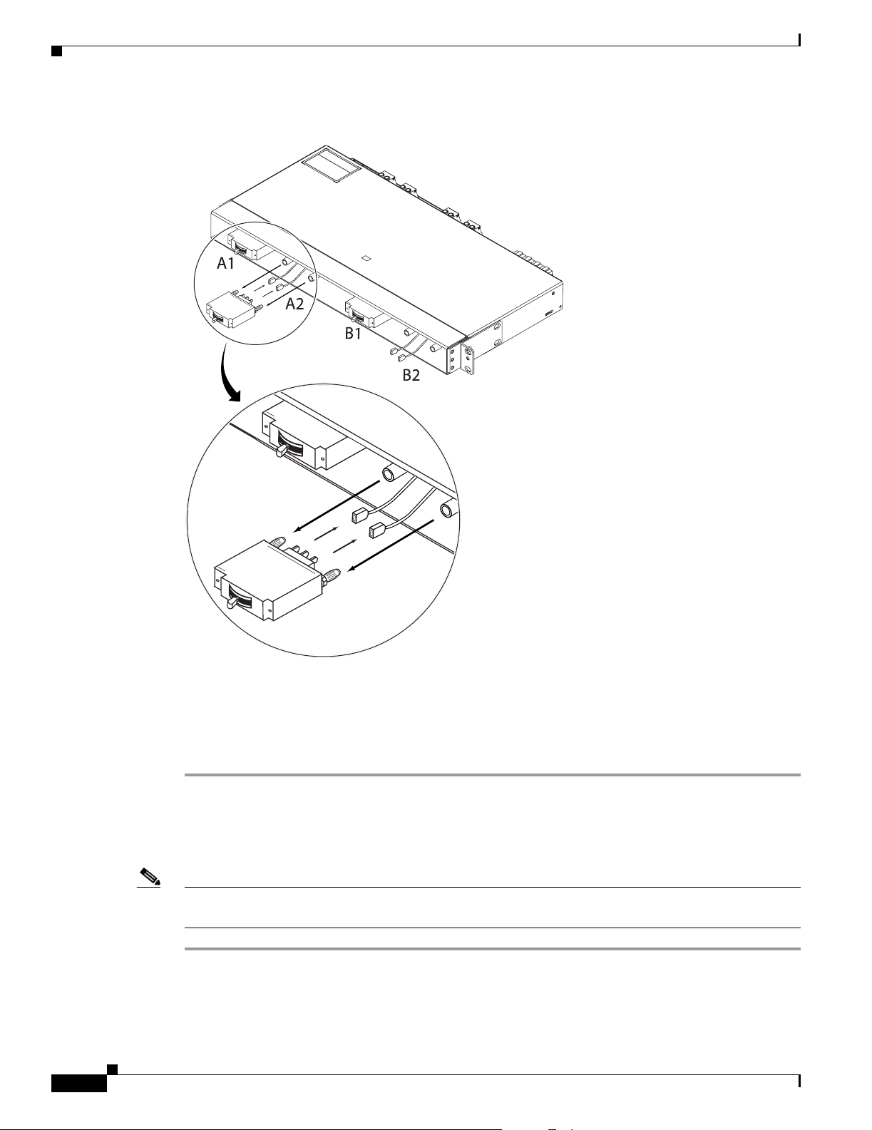
3.2.4 Replace a Rectifier
Chapter 3 Component Replacement
Figure 3-8 Removing a Circuit Breaker
Step 5
Step 6 Pull the breaker straight out from the 1RU Distribution Shelf.
Step 7 To reinstall a replacement 1RU Distribution Shelf see the “2.2.2 Install the 1 RU Distribution Shelf”
Remove the alarm cable connections from the rear of the breaker (Figure 3-8).
procedure on page 2-6.
3.2.4 Replace a Rectifier
Note For more information on uninstalling a rectifier, see the “4.2.2.3 Remove Modules” section on
page 4-3.
Step 1 Locate the rectifier that is to be removed.
Step 2 Loosen the mounting screws to allow the rectifier handle to open (Figure 3-9 #1).
Step 3 Grasp the top of the handle and pull down until the handle locks into the open position (Figure 3-9 #2).
124757
3-8
Cisco AC/DC Power System User Guide, R1.0
May 2006
Page 67

Chapter 3 Component Replacement
Figure 3-9 Removing a Rectifier
1
3.2.4 Replace a Rectifier
2
124787
Step 4
Caution The rectifier module may be hot when being pulled from the shelf. To avoid personal injury, wait until
Step 5 Continue to pull the rectifier until it is halfway out of the shelf. Grasp the bottom of the rectifier with
Step 6 Pull the rectifier out of the shelf. The system will generate a communication error, which will last until
Step 7 For information on installing a rectifier module, see the “2.3.1 Install the Rectifiers” procedure on
Grasp the handle and gently pull the module out and away from the shelf.
the rectifier has cooled before removing from the system shelf.
one hand and continue using the other hand to pull the rectifier out.
a new rectifier is inserted.
page 2-16.
May 2006
Cisco AC/DC Power System User Guide, R1.0
3-9
Page 68

3.2.5 Replace GMT Fuses
3.2.5 Replace GMT Fuses
Step 1 Locate the GMT fuse that is to be removed.
Step 2 Grasp the fuse firmly at the front and pull out (Figure 3-10).
Figure 3-10 Removing a GMT Fuse
Chapter 3 Component Replacement
124772
Step 3 For information on installing GMT fuses, see the “2.5.1 Install GMT Fuse Connections” procedure on
page 2-25.
Caution When replacing GMT fuses, always use the same size fuse unless the GMT fuse output cabling is
upgraded as well. For more information on the appropriate cable/fuse sizes, see Table 1-2 on page 1-6.
3-10
Cisco AC/DC Power System User Guide, R1.0
May 2006
Page 69

System Operation
4.1 System Commissioning
The following section should be used to power-up the system for the first time.
Step 1 Turn on AC breakers at the AC distribution panel to power up the shelf through the rectifiers.
Step 2 The controller and rectifier LEDs will start to blink. It may take a few minutes for the controller to
communicate with all rectifiers.
Step 3 The system is now commissioned. If the controller RED LED s on, refer to “Chapter 5, “System
Troubleshooting.”
CHA PTER
4
4.2 General Information
The Power Control System (XCS) (Figure 4-1) is a supervisory system that is designed to control
AC/DC power systems that are based on XR1648 rectifier modules.
Communication is accomplished through an alarm interface board and a backplane that connects to the
rectifier modules.
Figure 4-1 System Control Unit
124780
May 2006
Cisco AC/DC Power System User Guide, R1.0
4-1
Page 70

4.2.1 Alarm Interface Board and Connections
4.2.1 Alarm Interface Board and Connections
The alarm interface board is the main connection point for external communication inputs. The board is
located inside the controller and can be accessed by removing the front controller cover and then sliding
out the controller tray to expose the alarm connections (located on the right-hand side).
Alarm connections are made at the terminal block located on the Alarm/Interface PC board. The green
connectors can be easily removed for ease in installing the wires into the connector; 22 AWG (0.34mm²)
wire is recommended for connecting alarms to the alarm output terminals (Figure 2-21 on page 2-24).
External connections are Form C relay which can be monitored either Normally Closed or Normally
Open. The four alarms are numbered 1 through 4. (Refer to Table 2-6 on page 2-23).
Note All alarm connections are for the unpowered state. When the power is off the NC is normally closed and
when the power is on, the NC is open.
The following is a list of alarm board connections including descriptions and cabling:
• Alarms - Up to four Form C alarm contacts for remote signaling
• Load fuse and breaker monitoring
• RS232 Interface - External communications port (not utilized in this application)
Chapter 4 System Operation
4.2.2 Basic Controller Functions
The following section contains basic controller functions including starting the controller, adding
modules, and removing modules from the system.
4.2.2.1 Start the Controller
When power is applied to the controller:
Step 1 The controller will spend several minutes analyzing the system and testing all addresses for connected
rectifier modules. The green LED on the controller will blink. No alarms will be raised during this
period.
Step 2 When the controller finds a module it will add it to the inventory.
4.2.2.2 Add Modules
When a rectifier is added to the system it will remain off until the controller detects it.
Step 1 When a rectifier is added to the system, its output voltage will walk-in, increasing up to its default
setting. This will occur within 60 seconds.
Step 2 The controller constantly scans for new modules, but it may take a few minutes to recognize an inserted
module.
4-2
Cisco AC/DC Power System User Guide, R1.0
May 2006
Page 71

Chapter 4 System Operation
Step 3 During this recognition time the controller may report module-related alarms and the red LED on the
rectifier may turn on. These alarms are caused by imbalances related to load sharing of the rectifiers (the
new rectifier’s output voltage is different than the existing rectifiers).
Step 4 The rectifier module will take a few minutes to step up to the correct voltage. At this point the controller
will locate and adjust the rectifier module voltage to the correct output voltage and any alarms will be
extinguished.
Step 5 To shorten the time that is needed to find new modules, the controller can be powered down and then
powered up. This will cause the system to search for new modules faster. This is only recommended as
a solution if it is important to shorten the time required for searching for new modules.
4.2.2.3 Remove Modules
Physically removing a module from the system creates a communication error indicated by the yellow
LED on the controller. The yellow LED will remain on until a rectifier is installed.
4.2.2 Basic Controller Functions
May 2006
Cisco AC/DC Power System User Guide, R1.0
4-3
Page 72

4.2.2 Basic Controller Functions
Chapter 4 System Operation
4-4
Cisco AC/DC Power System User Guide, R1.0
May 2006
Page 73

CHA PTER
5
System Troubleshooting
This chapter contains information about troubleshooting and should be consulted in the event of a system
malfunction.
The following is a list of potential problems and resolutions. If the first recommendation does not solve
the problem, continue on to the next. If further assistance is needed, see the “Obtaining Technical
Assistance” section on page xiv.
Warning
Note Most alarms will clear automatically when the cause has been cleared. Some alarms can be cancelled via
Only trained and qualified personnel should be allowed to install, replace, or service this equipment.
Statement 1030
the front panel push-buttons. In this case it will be indicated in the trouble shooting instructions.
Error Message Low System Voltage (Red light on controller, Relay #1)
Explanation
Rectifier failure
1.
2. Loss of AC power on some or all rectifiers
3. Load exceeds rectifier capacity
Recommended Action
1.
Replace faulty rectifier
2. Add one or more rectifiers to the system
Error Message Mains Error (Yellow light on controller, Relay #2)
May 2006
Explanation
Recommended Action
Verify that the AC supply is available at the correct voltage
1.
2. Verify that the AC input breaker is in the ON position
AC supply off on two or more rectifiers
Cisco AC/DC Power System User Guide, R1.0
5-1
Page 74
Chapter 5 System Troubleshooting
Error Message Distribution Fuse/Breaker Failure (Red light on controller, Relay #4)
Explanation
Tripped breaker
1.
2. Fuse blown
Recommended Action
1.
Localize the faulty breaker or blown fuse
2. Verify there are no short circuits in the cabling to the load
3. Reset breaker. If it trips again there is a problem with the breaker or the load
4. Replace breaker if required
5. Verify that there is no blown fuse. (If so, replace the blown fuse.) If the fuse blows again, there
may be a problem with the load
Note Due to proprietary alarm wiring, a voltage will appear at the load terminal of the fuse even when
the fuse is open. The voltage comes from a high impedance circuit used for blown fuse detection
when a load is connected. This is not an energy hazard.
Error Message High Load (Yellow light on controller)
Explanation
Recommended Action
1.
Check load current versus installed rectifier capacity. The alarm is generated when output load
Load current exceeds 75%
reaches 75% of rectifier capacity.
2. Add rectifier or reduce load.
Error Message Module Failure (Red light on controller and Module, Relay #3)
Explanation
Module failure
1.
2. AC Off on a single rectifier
3. Current sharing fault
Recommended Action
Verify that the AC supply to the failed module is present at the right voltage.
1.
2. Remove the faulty module, wait 30 seconds, and re-insert it. Wait up to four minutes for the
controller to re-establish communication. If the module is still faulty, replace it with a new
module.
5-2
3. Verify module address and resolve any address duplication (Figure 5-1). Rectifier address DIP
switches are located at the inside rear of the rectifier shelf.
Cisco AC/DC Power System User Guide, R1.0
May 2006
Page 75
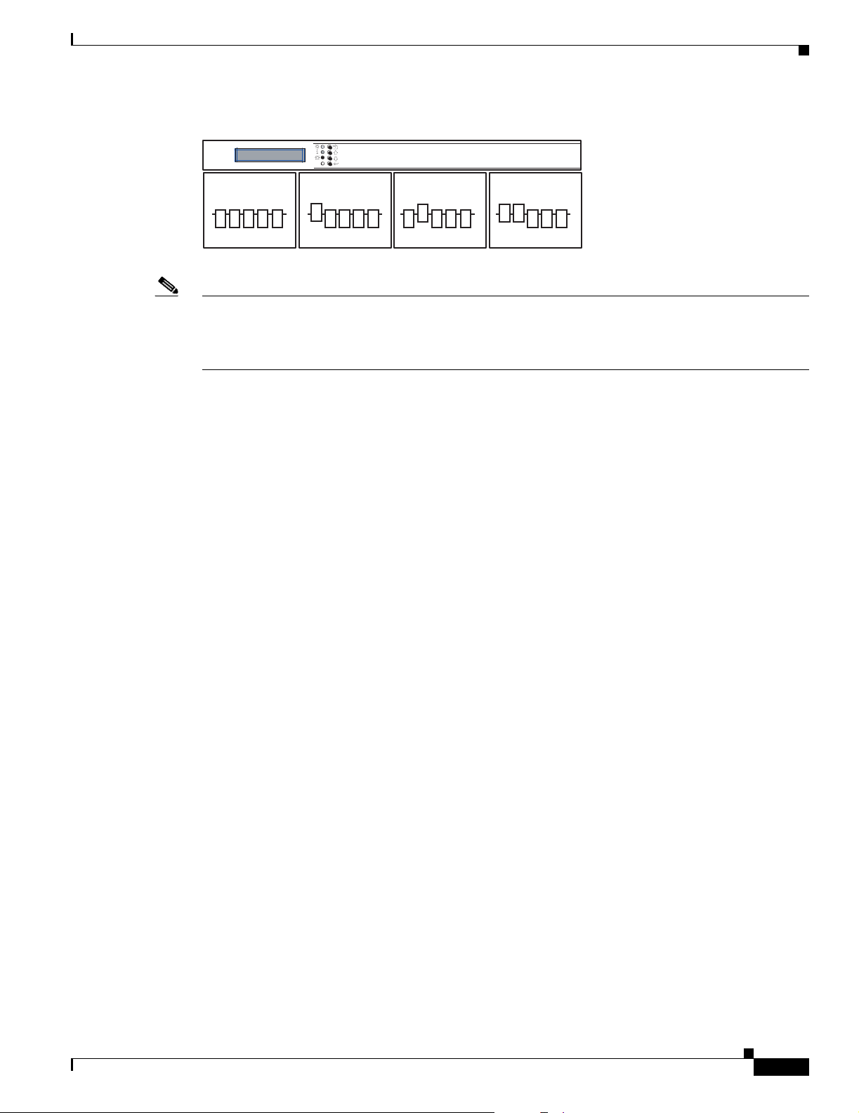
Chapter 5 System Troubleshooting
Figure 5-1 Module Locations
124816 124816 124816 124816
Note Sometimes the rectifier that indicates a failure is not the cause of the failure. The failure may be caused
by a current share imbalance. If the failure persists even after replacing the rectifiers showing a fault,
replace each rectifier in turn with a known good unit until the fault clears. The replaced module that
clears the fault is the defective one.
Error Message Urgent Module Failure (Red light on controller, Relay #3)
124777
Explanation
Recommended Action See module failure.
Error Message Communication Failure (Yellow light on controller, flashing yellow
light on module)
Explanation
Controller is looking for the installed module
1.
2. A module has been removed and not replaced
3. Broken or disconnected communication wire
Recommended Action
Wait for 5 minutes.
1.
2. Verify that the module address is properly set and is not a duplicate of another address
More than one rectifier is reporting a module failure.
(Figure 5-1). Rectifier address DIP switches are located at the inside rear of the rectifier shelf.
3. Verify that the communication cable at the back of the rectifier shelf is connected.
4. Replace communication cable if required.
May 2006
Cisco AC/DC Power System User Guide, R1.0
5-3
Page 76

Chapter 5 System Troubleshooting
5-4
Cisco AC/DC Power System User Guide, R1.0
May 2006
Page 77

CHA PTER
6
System Parts List
This chapter contains a list of replacement parts and part numbers for the Cisco AC/DC Power System.
Table 6-1 Parts List
Description Part Number
Main Shelf Assembly CSCO-SM-PWR-SA
Rectifier Module CSCO-PWR-RECT
Controller Module CSCO-CNTRL-BRD
1RU DC Distribution Shelf CSCO-EXP-PANEL
30A Circuit Breaker CSCO-CKT-BRK
Ship Kit for Main Shelf Assembly CSCO-SHP-KIT-1
Ship Kit for 1RU DC Distribution Shelf CSCO-SHP-KIT-2
AC Power Cable for 110V AC North America CSCO-PWR-CBL-NA1
AC Power Cable for 220V AC North America CSCO-PWR-CBL-NA2
AC Power Cable for Argentina CSCO-PWR-CBL-ARG
AC Power Cable for Australia CSCO-PWR-CBL-AUS
AC Power Cable for China CSCO-PWR-CBL-CHN
AC Power Cable for EU Member Nations CSCO-PWR-CBL-EU
AC Power Cable for Italy CSCO-PWR-CBL-ITL
AC Power Cable for Japan CSCO-PWR-CBL-JPN
AC Power Cable for The United Kingdom CSCO-PWR-CBL-UK
May 2006
Cisco AC/DC Power System User Guide, R1.0
6-1
Page 78

Chapter 6 System Parts List
6-2
Cisco AC/DC Power System User Guide, R1.0
May 2006
Page 79

APPENDIX
A
Translated Safety Warnings
This appendix contains the translated warnings included in the Cisco AC/DC Power System user
documentation.
The translated safety warnings are listed in the following order:
1 English 10 Swedish 19 Croatian (in some)
2 Dutch 11 Hungarian 20 Czech (in some)
3 Finnish 12 Russian 21 Greek (in some)
4 French 13 Chinese 22 Hebrew (in some)
5 German 14 Japanese 23 Macedonian (in some)
6 Italian 15 Korean (in some) 24 Polish (in some)
7 Norwegian 16 Brazilian Portuguese (in some) 25 Slovakian (in some)
8 Portuguese 17 Danish (in some)
9 Spanish 18 Arabic (in some)
Statement 12—Power Supply Disconnection Warning
Warning
Waarschuwing
Varoitus
Attention
May 2006
Before working on a chassis or working near power supplies, unplug the power cord on AC units;
disconnect the power at the circuit breaker on DC units.
Voordat u aan een frame of in de nabijheid van voedingen werkt, dient u bij wisselstroom toestellen
de stekker van het netsnoer uit het stopcontact te halen; voor gelijkstroom toestellen dient u de
stroom uit te schakelen bij de stroomverbreker.
Kytke irti vaihtovirtalaitteiden virtajohto ja katkaise tasavirtalaitteiden virta suojakytkimellä, ennen
kuin teet mitään asennuspohjalle tai työskentelet virtalähteiden läheisyydessä.
Avant de travailler sur un châssis ou à proximité d'une alimentation électrique, débrancher le
cordon d'alimentation des unités en courant alternatif ; couper l'alimentation des unités en courant
continu au niveau du disjoncteur.
Statement 12
Cisco AC/DC Power System User Guide, R1.0
A-1
Page 80

Appendix A Translated Safety Warnings
Warnung
Avvertenza
Advarsel
Aviso
¡Advertencia!
Varning!
Bevor Sie an einem Chassis oder in der Nähe von Netzgeräten arbeiten, ziehen Sie bei
Wechselstromeinheiten das Netzkabel ab bzw. schalten Sie bei Gleichstromeinheiten den Strom am
Unterbrecher ab.
Prima di lavorare su un telaio o intorno ad alimentatori, scollegare il cavo di alimentazione sulle
unità CA; scollegare l'alimentazione all’interruttore automatico sulle unità CC.
Før det utføres arbeid på kabinettet eller det arbeides i nærheten av strømforsyningsenheter, skal
strømledningen trekkes ut på vekselstrømsenheter og strømmen kobles fra ved strømbryteren på
likestrømsenheter.
Antes de trabalhar num chassis, ou antes de trabalhar perto de unidades de fornecimento de
energia, desligue o cabo de alimentação nas unidades de corrente alternada; desligue a corrente
no disjuntor nas unidades de corrente contínua.
Antes de manipular el chasis de un equipo o trabajar cerca de una fuente de alimentación,
desenchufar el cable de alimentación en los equipos de corriente alterna (CA); cortar la
alimentación desde el interruptor automático en los equipos de corriente continua (CC).
I
nnan du arbetar med ett chassi eller nära strömförsörjningsenheter skall du för växelströmsenheter
dra ur nätsladden och för likströmsenheter bryta strömmen vid överspänningsskyddet.
A-2
Cisco AC/DC Power System User Guide, R1.0
May 2006
Page 81

Appendix A Translated Safety Warnings
Statement 43—Jewelry Removal Warning
Warning
Waarschuwing
Varoitus
Attention
Warnung
Avvertenza
Before working on equipment that is connected to power lines, remove jewelry (including rings,
necklaces, and watches). Metal objects will heat up when connected to power and ground and can
cause serious burns or weld the metal object to the terminals.
Statement 43
Alvorens aan apparatuur te werken die met elektrische leidingen is verbonden, sieraden (inclusief
ringen, kettingen en horloges) verwijderen. Metalen voorwerpen worden warm wanneer ze met
stroom en aarde zijn verbonden, en kunnen ernstige brandwonden veroorzaken of het metalen
voorwerp aan de aansluitklemmen lassen.
Ennen kuin työskentelet voimavirtajohtoihin kytkettyjen laitteiden parissa, ota pois kaikki korut
(sormukset, kaulakorut ja kellot mukaan lukien). Metalliesineet kuumenevat, kun ne ovat
yhteydessä sähkövirran ja maan kanssa, ja ne voivat aiheuttaa vakavia palovammoja tai hitsata
metalliesineet kiinni liitäntänapoihin.
Avant d’accéder à cet équipement connecté aux lignes électriques, ôter tout bijou (anneaux,
colliers et montres compris). Lorsqu’ils sont branchés à l’alimentation et reliés à la terre, les objets
métalliques chauffent, ce qui peut provoquer des blessures graves ou souder l’objet métallique aux
bornes.
Vor der Arbeit an Geräten, die an das Netz angeschlossen sind, jeglichen Schmuck (einschließlich
Ringe, Ketten und Uhren) abnehmen. Metallgegenstände erhitzen sich, wenn sie an das Netz und die
Erde angeschlossen werden, und können schwere Verbrennungen verursachen oder an die
Anschlußklemmen angeschweißt werden.
Prima di intervenire su apparecchiature collegate alle linee di alimentazione, togliersi qualsiasi
monile (inclusi anelli, collane, braccialetti ed orologi). Gli oggetti metallici si riscaldano quando
sono collegati tra punti di alimentazione e massa: possono causare ustioni gravi oppure il metallo
può saldarsi ai terminali.
¡Advertencia!
May 2006
Advarsel
Aviso
Varning!
Fjern alle smykker (inkludert ringer, halskjeder og klokker) før du skal arbeide på utstyr som er
koblet til kraftledninger. Metallgjenstander som er koblet til kraftledninger og jord blir svært varme
og kan forårsake alvorlige brannskader eller smelte fast til polene.
Antes de trabalhar em equipamento que esteja ligado a linhas de corrente, retire todas as jóias que
estiver a usar (incluindo anéis, fios e relógios). Os objectos metálicos aquecerão em contacto com
a corrente e em contacto com a ligação à terra, podendo causar queimaduras graves ou ficarem
soldados aos terminais.
Antes de operar sobre equipos conectados a líneas de alimentación, quitarse las joyas (incluidos
anillos, collares y relojes). Los objetos de metal se calientan cuando se conectan a la alimentación
y a tierra, lo que puede ocasionar quemaduras graves o que los objetos metálicos queden soldados
a los bornes.
Tag av alla smycken (inklusive ringar, halsband och armbandsur) innan du arbetar på utrustning som
är kopplad till kraftledningar. Metallobjekt hettas upp när de kopplas ihop med ström och jord och
kan förorsaka allvarliga brännskador; metallobjekt kan också sammansvetsas med kontakterna.
Cisco AC/DC Power System User Guide, R1.0
A-3
Page 82

Appendix A Translated Safety Warnings
Statement 1006—Chassis Warning for Rack-Mounting and Servicing
Warning
Waarschuwing
To prevent bodily injury when mounting or servicing this unit in a rack, you must take special
precautions to ensure that the system remains stable. The following guidelines are provided to
ensure your safety:
• This unit should be mounted at the bottom of the rack if it is the only unit in the rack.
• When mounting this unit in a partially filled rack, load the rack from the bottom to the top with the heaviest
component at the bottom of the rack.
• If the rack is provided with stabilizing devices, install the stabilizers before mounting or servicing the unit in
the rack.
Statement 1006
Om lichamelijk letsel te voorkomen wanneer u dit toestel in een rek monteert of het daar een
servicebeurt geeft, moet u speciale voorzorgsmaatregelen nemen om ervoor te zorgen dat het toestel
stabiel blijft. De onderstaande richtlijnen worden verstrekt om uw veiligheid te verzekeren:
• Dit toestel dient onderaan in het rek gemonteerd te worden als het toestel het enige in het rek is.
• Wanneer u dit toestel in een gedeeltelijk gevuld rek monteert, dient u het rek van onderen naar boven te laden
met het zwaarste onderdeel onderaan in het rek.
• Als het rek voorzien is van stabiliseringshulpmiddelen, dient u de stabilisatoren te monteren voordat u het
toestel in het rek monteert of het daar een servicebeurt geeft.
A-4
Cisco AC/DC Power System User Guide, R1.0
May 2006
Page 83

Appendix A Translated Safety Warnings
Varoitus
Attention
Warnung
Kun laite asetetaan telineeseen tai huolletaan sen ollessa telineessä, on noudatettava erityisiä
varotoimia järjestelmän vakavuuden säilyttämiseksi, jotta vältytään loukkaantumiselta. Noudata
seuraavia turvallisuusohjeita:
• Jos telineessä ei ole muita laitteita, aseta laite telineen alaosaan.
• Jos laite asetetaan osaksi täytettyyn telineeseen, aloita kuormittaminen sen alaosasta kaikkein raskaimmalla
esineellä ja siirry sitten sen yläosaan.
• Jos telinettä varten on vakaimet, asenna ne ennen laitteen asettamista telineeseen tai sen huoltamista siinä.
Pour éviter toute blessure corporelle pendant les opérations de montage ou de réparation de cette
unité en casier, il convient de prendre des précautions spéciales afin de maintenir la stabilité du
système. Les directives ci-dessous sont destinées à assurer la protection du personnelþ:
• Si cette unité constitue la seule unité montée en casier, elle doit être placée dans le bas.
• Si cette unité est montée dans un casier partiellement rempli, charger le casier de bas en haut en plaçant
l'élément le plus lourd dans le bas.
• Si le casier est équipé de dispositifs stabilisateurs, installer les stabilisateurs avant de monter ou de réparer
l'unité en casier.
Zur Vermeidung von Körperverletzung beim Anbringen oder Warten dieser Einheit in einem Gestell
müssen Sie besondere Vorkehrungen treffen, um sicherzustellen, daß das System stabil bleibt. Die
folgenden Richtlinien sollen zur Gewährleistung Ihrer Sicherheit dienen:
• Wenn diese Einheit die einzige im Gestell ist, sollte sie unten im Gestell angebracht werden.
• Bei Anbringung dieser Einheit in einem zum Teil gefüllten Gestell ist das Gestell von unten nach oben zu laden,
wobei das schwerste Bauteil unten im Gestell anzubringen ist.
• Wird das Gestell mit Stabilisierungszubehör geliefert, sind zuerst die Stabilisatoren zu installieren, bevor Sie
die Einheit im Gestell anbringen oder sie warten.
Avvertenza
Advarsel
Per evitare infortuni fisici durante il montaggio o la manutenzione di questa unità in un supporto,
occorre osservare speciali precauzioni per garantire che il sistema rimanga stabile. Le seguenti
direttive vengono fornite per garantire la sicurezza personale:
• Questa unità deve venire montata sul fondo del supporto, se si tratta dell’unica unità da montare nel supporto.
• Quando questa unità viene montata in un supporto parzialmente pieno, caricare il supporto dal basso all’alto,
con il componente più pesante sistemato sul fondo del supporto.
• Se il supporto è dotato di dispositivi stabilizzanti, installare tali dispositivi prima di montare o di procedere alla
manutenzione dell’unità nel supporto.
Unngå fysiske skader under montering eller reparasjonsarbeid på denne enheten når den befinner
seg i et kabinett. Vær nøye med at systemet er stabilt. Følgende retningslinjer er gitt for å verne
om sikkerheten:
• Denne enheten bør monteres nederst i kabinettet hvis dette er den eneste enheten i kabinettet.
• Ved montering av denne enheten i et kabinett som er delvis fylt, skal kabinettet lastes fra bunnen og opp med
den tyngste komponenten nederst i kabinettet.
• Hvis kabinettet er utstyrt med stabiliseringsutstyr, skal stabilisatorene installeres før montering eller utføring
av reparasjonsarbeid på enheten i kabinettet.
May 2006
Cisco AC/DC Power System User Guide, R1.0
A-5
Page 84

Appendix A Translated Safety Warnings
Aviso
¡Advertencia!
Varning!
Para se prevenir contra danos corporais ao montar ou reparar esta unidade numa estante, deverá
tomar precauções especiais para se certificar de que o sistema possui um suporte estável. As
seguintes directrizes ajudá-lo-ão a efectuar o seu trabalho com segurança:
• Esta unidade deverá ser montada na parte inferior da estante, caso seja esta a única unidade a ser montada.
• Ao montar esta unidade numa estante parcialmente ocupada, coloque os itens mais pesados na parte inferior
da estante, arrumando-os de baixo para cima.
• Se a estante possuir um dispositivo de estabilização, instale-o antes de montar ou reparar a unidade.
Para evitar lesiones durante el montaje de este equipo sobre un bastidor, o posteriormente durante
su mantenimiento, se debe poner mucho cuidado en que el sistema quede bien estable. Para
garantizar su seguridad, proceda según las siguientes instrucciones:
• Colocar el equipo en la parte inferior del bastidor, cuando sea la única unidad en el mismo.
• Cuando este equipo se vaya a instalar en un bastidor parcialmente ocupado, comenzar la instalación desde la
parte inferior hacia la superior colocando el equipo más pesado en la parte inferior.
• Si el bastidor dispone de dispositivos estabilizadores, instalar éstos antes de montar o proceder al
mantenimiento del equipo instalado en el bastidor.
För att undvika kroppsskada när du installerar eller utför underhållsarbete på denna enhet på en
ställning måste du vidta särskilda försiktighetsåtgärder för att försäkra dig om att systemet står
stadigt. Följande riktlinjer ges för att trygga din säkerhet:
• Om denna enhet är den enda enheten på ställningen skall den installeras längst ned på ställningen.
• Om denna enhet installeras på en delvis fylld ställning skall ställningen fyllas nedifrån och upp, med de tyngsta
enheterna längst ned på ställningen.
• Om ställningen är försedd med stabiliseringsdon skall dessa monteras fast innan enheten installeras eller
underhålls på ställningen.
A-6
•
•
•
•
•
•
Cisco AC/DC Power System User Guide, R1.0
May 2006
Page 85

Appendix A Translated Safety Warnings
•
•
•
Aviso
Advarsel
Para evitar lesões corporais ao montar ou dar manutenção a esta unidade em um rack, é necessário
tomar todas as precauções para garantir a estabilidade do sistema. As seguintes orientações são
fornecidas para garantir a sua segurança:
• Se esta for a única unidade, ela deverá ser montada na parte inferior do rack.
• Ao montar esta unidade em um rack parcialmente preenchido, carregue-o de baixo para cima com o
componente mais pesado em sua parte inferior.
• Se o rack contiver dispositivos estabilizadores, instale-os antes de montar ou dar manutenção à unidade
existente.
For at forhindre legemesbeskadigelse ved montering eller service af denne enhed i et rack, skal du
sikre at systemet står stabilt. Følgende retningslinjer er også for din sikkerheds skyld:
• Enheden skal monteres i bunden af dit rack, hvis det er den eneste enhed i racket.
• Ved montering af denne enhed i et delvist fyldt rack, skal enhederne installeres fra bunden og opad med den
tungeste enhed nederst.
• Hvis racket leveres med stabiliseringsenheder, skal disse installeres for enheden monteres eller serviceres i
racket.
May 2006
Cisco AC/DC Power System User Guide, R1.0
A-7
Page 86

Appendix A Translated Safety Warnings
A-8
Cisco AC/DC Power System User Guide, R1.0
May 2006
Page 87

Appendix A Translated Safety Warnings
Statement 1017—Restricted Area
Warning
Waarschuwing
Varoitus
Attention
Warnung
This unit is intended for installation in restricted access areas. A restricted access area can be
accessed only through the use of a special tool, lock and key, or other means of security.
Statement 1017
Deze eenheid is bestemd voor installatie in plaatsen met beperkte toegang. Toegang tot een
dergelijke plaats kan alleen verkregen worden door middel van een speciaal instrument, een slot
en sleutel of een ander veiligheidsmiddel.
Tämä laite on tarkoitettu asennettavaksi paikkaan, johon pääsy on rajoitettua. Tällaiseen paikkaan
pääsee vain erikoistyökalua, lukkoon sopivaa avainta tai jotakin muuta turvalaitetta käyttämällä.
Cet appareil est à installer dans des zones d'accès réservé. L'accès à une zone d'accès réservé n'est
possible qu'en utilisant un outil spécial, un mécanisme de verrouillage et une clé, ou tout autre
moyen de sécurité.
Diese Einheit ist zur Installation in Bereichen mit beschränktem Zutritt vorgesehen. Der Zutritt zu
derartigen Bereichen ist nur mit einem Spezialwerkzeug, Schloss und Schlüssel oder einer
sonstigen Sicherheitsvorkehrung möglich.
May 2006
Cisco AC/DC Power System User Guide, R1.0
A-9
Page 88

Appendix A Translated Safety Warnings
Avvertenza
Advarsel
Aviso
¡Advertencia!
Varning!
Questa unità è prevista per essere installata in un'area ad accesso limitato, vale a dire un'area
accessibile solo mediante l'uso di un attrezzo speciale, come lucchetto e chiave, o altri dispositivi
di sicurezza.
Denne enheten er beregnet på installasjon i områder med begrenset tilgang. Et begrenset
tilgangsområde kan bare nås ved hjelp av et spesielt verktøy, lås og nøkkel, eller andre
sikkerhetsanordninger.
Esta unidade foi concebida para instalação em áreas de acesso restrito. Uma área de acesso restrito
é uma área à qual apenas tem acesso o pessoal de serviço autorizado, que possua uma ferramenta,
chave e fechadura especial, ou qualquer outra forma de segurança.
Esta unidad ha sido diseñada para instalación en áreas de acceso restringido. Sólo puede obtenerse
acceso a una de estas áreas mediante la utilización de una herramienta especial, cerradura con
llave u otro medio de seguridad.
Denna enhet är avsedd för installation i områden med begränsat tillträde. Ett område med begränsat
tillträde kan endast tillträdas med hjälp av specialverktyg, lås och nyckel eller annan
säkerhetsanordning.
Aviso
Advarsel
Esta unidade deve ser instalada em áreas de acesso restrito. Uma área de acesso restrito só pode
ser acessada com o uso de uma ferramenta especial, cadeado e chave ou outros meios de
segurança.
Denne enhed er beregnet til installation i områder med begrænset adgang. Der kan kun opnås
adgang til et begrænset område ved at bruge et særligt stykke værktøj, lås og nøgle, eller en anden
form for sikkerhed.
A-10
Cisco AC/DC Power System User Guide, R1.0
May 2006
Page 89

Appendix A Translated Safety Warnings
Statement 1024—Ground Conductor
Warning
Waarschuwing
Varoitus
May 2006
This equipment must be grounded. Never defeat the ground conductor or operate the equipment in
the absence of a suitably installed ground conductor. Contact the appropriate electrical inspection
authority or an electrician if you are uncertain that suitable grounding is available.
Deze apparatuur dient geaard te zijn. De aardingsleiding mag nooit buiten werking worden gesteld
en de apparatuur mag nooit bediend worden zonder dat er een op de juiste wijze geïnstalleerde
aardingsleiding aanwezig is. Neem contact op met de bevoegde instantie voor elektrische
inspecties of met een elektricien als u er niet zeker van bent dat er voor passende aarding
gezorgd is.
Laitteiden on oltava maadoitettuja. Älä koskaan ohita maajohdinta tai käytä laitteita ilman oikein
asennettua maajohdinta. Ota yhteys sähkötarkastusviranomaiseen tai sähköasentajaan, jos olet
epävarma maadoituksen sopivuudesta.
Statement 1024
Cisco AC/DC Power System User Guide, R1.0
A-11
Page 90

Appendix A Translated Safety Warnings
Attention
Warnung
Avvertenza
Advarsel
Aviso
¡Advertencia!
Cet équipement doit être mis à la masse. Ne jamais rendre inopérant le conducteur de masse ni
utiliser l'équipement sans un conducteur de masse adéquatement installé. En cas de doute sur la
mise à la masse appropriée disponible, s'adresser à l'organisme responsable de la sécurité
électrique ou à un électricien.
Dieses Gerät muss geerdet sein. Auf keinen Fall den Erdungsleiter unwirksam machen oder das
Gerät ohne einen sachgerecht installierten Erdungsleiter verwenden. Wenn Sie sich nicht sicher
sind, ob eine sachgerechte Erdung vorhanden ist, wenden Sie sich an die zuständige
Inspektionsbehörde oder einen Elektriker.
Questa apparecchiatura deve essere dotata di messa a terra. Non escludere mai il conduttore di
protezione né usare l'apparecchiatura in assenza di un conduttore di protezione installato in modo
corretto. Se non si è certi della disponibilità di un adeguato collegamento di messa a terra,
richiedere un controllo elettrico presso le autorità competenti o rivolgersi a un elettricista.
Dette utstyret må jordes. Omgå aldri jordingslederen og bruk aldri utstyret uten riktig montert
jordingsleder. Ta kontakt med fagfolk innen elektrisk inspeksjon eller med en elektriker hvis du er
usikker på om det finnes velegnet jordning.
Este equipamento deve ser aterrado. Nunca anule o fio terra nem opere o equipamento sem um
aterramento adequadamente instalado. Em caso de dúvida com relação ao sistema de aterramento
disponível, entre em contato com os serviços locais de inspeção elétrica ou um eletricista
qualificado.
Este equipo debe estar conectado a tierra. No inhabilite el conductor de tierra ni haga funcionar el
equipo si no hay un conductor de tierra instalado correctamente. Póngase en contacto con la
autoridad correspondiente de inspección eléctrica o con un electricista si no está seguro de que
haya una conexión a tierra adecuada.
Varning!
Denna utrustning måste jordas. Koppla aldrig från jordledningen och använd aldrig utrustningen
utan en på lämpligt sätt installerad jordledning. Om det föreligger osäkerhet huruvida lämplig
jordning finns skall elektrisk besiktningsauktoritet eller elektriker kontaktas.
A-12
Cisco AC/DC Power System User Guide, R1.0
May 2006
Page 91

Appendix A Translated Safety Warnings
Statement 1030—Equipment Installation
Warning
Waarschuwing
Varoitus
Attention
Warnung
Avvertenza
Advarsel
Aviso
Only trained and qualified personnel should be allowed to install, replace, or service
this equipment.
Statement 1030
Deze apparatuur mag alleen worden geïnstalleerd, vervangen of hersteld door bevoegd
geschoold personeel.
Tämän laitteen saa asentaa, vaihtaa tai huoltaa ainoastaan koulutettu ja laitteen
tunteva henkilökunta.
Il est vivement recommandé de confier l'installation, le remplacement et la maintenance de ces
équipements à des personnels qualifiés et expérimentés.
Das Installieren, Ersetzen oder Bedienen dieser Ausrüstung sollte nur geschultem, qualifiziertem
Personal gestattet werden.
Questo apparato può essere installato, sostituito o mantenuto unicamente da un personale
competente.
Bare opplært og kvalifisert personell skal foreta installasjoner, utskiftninger eller service på
dette utstyret.
Apenas pessoal treinado e qualificado deve ser autorizado a instalar, substituir ou fazer a revisão
deste equipamento.
¡Advertencia!
Varning!
Aviso
Solamente el personal calificado debe instalar, reemplazar o utilizar este equipo.
Endast utbildad och kvalificerad personal bör få tillåtelse att installera, byta ut eller reparera
denna utrustning.
Somente uma equipe treinada e qualificada tem permissão para instalar, substituir ou dar
manutenção a este equipamento.
May 2006
Cisco AC/DC Power System User Guide, R1.0
A-13
Page 92
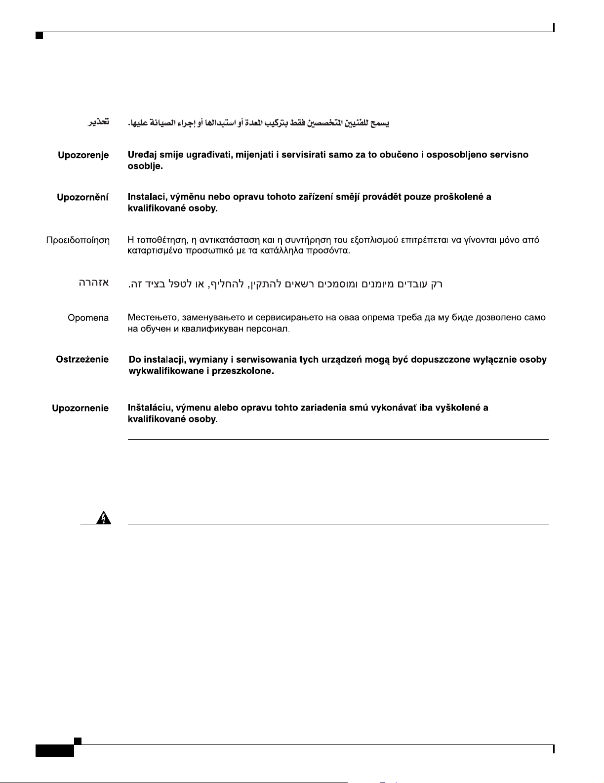
Appendix A Translated Safety Warnings
Advarsel
Kun uddannede personer må installere, udskifte komponenter i eller servicere dette udstyr.
Statement 1033—SELV-IEC 60950 DC Power Supply
Warning
Waarschuwing
Varoitus
Attention
Cisco AC/DC Power System User Guide, R1.0
A-14
Connect the unit only to DC power source that complies with the safety extra-low voltage (SELV)
requirements in IEC 60950 based safety standards.
Statement 1033
Sluit de eenheid alleen maar aan op een gelijkstroombron die voldoet aan de veiligheidsvereisten
voor extra-laag voltage (SELV) in de op IEC 60950 gebaseerde veiligheidsnormen.
Liitä laite ainoastaan tasavirtalähteesen, joka on yhdenmukainen IEC 60950:n suojattujen erittäisen
alhaisen jännitteen (SELV) turvavaatimusten kanssa.
Connectez l'unité uniquement à une alimentation CC compatible avec les recommandations SELV
(safety extra-low voltage) des normes de sécurité IEC 60950.
May 2006
Page 93

Appendix A Translated Safety Warnings
Warnung
Avvertenza
Advarsel
Aviso
¡Advertencia!
Varning!
Schließen Sie die Einheit nur an eine Gleichstrom-Stromquelle an, die mit den Safety Extra-Low
Voltage (SELV)-Anforderungen in den auf IEC 60950 basierenden Sicherheitsstandards
übereinstimmen.
Collegare l’unità esclusivamente a una presa di corrente continua rispondente ai requisiti SELV
(safety extra-low voltage) in base alle norme di sicurezza IEC 60950.
Koble bare enheten til en likestrømsforsyning som er i henhold til kravene for lavspenning (SELV)
i IEC 60950-baserte sikkerhetsstandarder.
Conecte a unidade apenas à fonte da energia de CC que se encontra em conformidade com os
requisitos dos circuitos de segurança de baixa tensão (SELV) constantes dos padrões de segurança
baseados no IEC 60950.
Conecte la unidad sólo en una fuente de energía DC que cumpla con los requisitos de voltaje extra
bajo (SELV - safety extra-low voltage) en los estándares de seguridad IEC 60950.
Anslut enheten endast till en likströmsförsörjningsenhet som uppfyller kraven för SELV
(skyddskretsar för mycket låg spänning) i IEC 60950-baserade säkerhetsstandarder.
Statement 1047—Overheating Prevention
Warning
Waarschuwing
To prevent the system from overheating, do not operate it in an area that exceeds the maximum
recommended ambient temperature of:
55°C (131°F)
Statement 1047
Om te voorkomen dat het systeem oververhit raakt, dient u het niet te gebruiken in een ruimte waar
de maximaal aanbevolen omgevingstemperatuur van
55°C (131°F) wordt overschreden.
May 2006
Cisco AC/DC Power System User Guide, R1.0
A-15
Page 94

Appendix A Translated Safety Warnings
Varoitus
Attention
Warnung
Avvertenza
Advarsel
Aviso
¡Advertencia!
Jotta järjestelmä ei kuumentuisi liikaa, sitä ei saa käyttää liian kuumassa ympäristössä.
Suosituksen mukainen käyttölämpötila on enintään
55°C (131°F)
Pour éviter toute surchauffe du système, il est recommandé de maintenir une température ambiante
inférieure à
55°C (131°F)
Um das System vor Überhitzung zu schützen, vermeiden Sie dessen Verwendung in einem Bereich,
in dem die Umgebungstemperatur das empfohlene Maximum von
55°C (131°F) überschreitet.
Per evitare che il sistema si surriscaldi, non utilizzatelo dove la temperatura ambiente sia superiore
alla temperatura massima raccomandata di
55°C (131°F)
For å hindre at systemet blir overopphetet, må det ikke brukes på et sted der temperaturen overstiger
den maksimalt anbefalte temperaturen på
55°C (131°F)
Para evitar o sobreaquecimento do sistema, não o opere em áreas que excedam a temperatura
ambiente máxima recomendada de
55°C (131°F)
Para impedir que el sistema se recaliente, no lo utilice en zonas en las que la temperatura ambiente
llegue a los
55°C (131°F)
Varning!
Förhindra att systemet överhettas genom att inte använda det på en plats där den rekommenderade
omgivningstemperaturen överstiger
55°C (131°F)
55°C (131°F)
55°C (131°F)
55°C (131°F)
55°C (131°F)
A-16
Cisco AC/DC Power System User Guide, R1.0
May 2006
Page 95

Appendix A Translated Safety Warnings
Statement 1074—Comply with Local and National Electrical Codes
Warning
Waarschuwing
Varoitus
Attention
Warnung
Avvertenza
Advarsel
Aviso
¡Advertencia!
Varning!
Installation of the equipment must comply with local and national electrical codes.
Statement 1074
Bij installatie van de apparatuur moet worden voldaan aan de lokale en nationale
elektriciteitsvoorschriften.
Laitteisto tulee asentaa paikallisten ja kansallisten sähkömääräysten mukaisesti.
L'équipement doit être installé conformément aux normes électriques nationales et locales.
Die Installation der Geräte muss den Sicherheitsstandards entsprechen.
L'installazione dell'impianto deve essere conforme ai codici elettrici locali e nazionali.
Installasjon av utstyret må samsvare med lokale og nasjonale elektrisitetsforskrifter.
A instalação do equipamento tem de estar em conformidade com os códigos eléctricos locais e
nacionais.
La instalación del equipo debe cumplir con las normativas de electricidad locales y nacionales.
Installation av utrustningen måste ske i enlighet med gällande elinstallationsföreskrifter.
May 2006
Cisco AC/DC Power System User Guide, R1.0
A-17
Page 96

Appendix A Translated Safety Warnings
A-18
Cisco AC/DC Power System User Guide, R1.0
May 2006
 Loading...