

Page 1

You'll be entered into a quarterly drawing for free Cisco Press books by returning this survey! Cisco is dedicated to customer
satisfaction and would like to hear your thoughts on these printed manuals. Please visit the Cisco Product Comments on-line survey at
www.cisco.com/go/crc to submit your comments about accessing Cisco technical manuals. Thank you for your time.
General Information
1 Years of networking experience: Years of experience with Cisco products:
2 I have these network types: LAN Backbone WA N
Other:
3 I have these Cisco products: Switches Routers
Other (specify models):
4 I perform these types of tasks: H/W installation and/or maintenance S/W configuration
Network management Other:
5 I use these types of documentation: H/W installation H/W configuration S/W configuration
Command reference Quick reference Release notes Online help
Other:
6 I access this information through: % Cisco.com % CD-ROM % Printed manuals
% Other:
7 I prefer this access method: Cisco.com CD-ROM Printed manuals
Other:
8 I use the following three product features the most:
Document Information
Document Title: Cisco 12016, Cisco 12416, and Cisco 12816 Router Installation and Configuration Guide
Part Number: OL-11495-01 S/W Release (if applicable):
On a scale of 1–5 (5 being the best), please let us know how we rate in the following areas:
The document is complete. The information is accurate.
The information is well organized. The information I wanted was easy to find.
The document is written at my
technical level of understanding.
Please comment on our lowest scores:
The information I found was useful to my job.
Mailing Information
Organization Date
Contact Name
Mailing Address
City State/Province Zip/Postal Code
Country Phone ( ) Extension
E-mail Fax ( )
May we contact you further concerning our documentation? Ye s No
You can also send us your comments by e-mail to bug-doc@cisco.com, or by fax to 408-527-8089.
When mailing this card from outside of the United States, please enclose in an envelope addressed to the location on the back of this card with
the required postage or fax to 1-408-527-8089.
Page 2
SAN JOSE CA 95134-9916
BUSINESS REPLY MAIL
FIRST-CLASS MAIL PERMIT NO. 4631 SAN JOSE CA
POSTAGE WILL BE PAID BY ADDRESSEE
DOCUMENT RESOURCE CONNECTION
CISCO SYSTEMS INC
170 WEST TASMAN DR
UNITED STATES
IN THE
NO POSTAGE
NECESSARY
IF MAILED
Page 3

Cisco 12016, Cisco 12416, and Cisco 12816 Router Installation and Configuration Guide
Corporate Headquarters
Cisco Systems, Inc.
170 West Tasman Drive
San Jose, CA 95134-1706
USA
http://www.cisco.com
Tel: 408 526-4000
800 553-NETS (6387)
Fax: 408 526-4100
Text Part Number: OL-11495-01
Page 4

THE SPECIFICATIONS AND INFORMATION REGARDING THE PRODUCTS IN THIS MANUAL ARE SUBJECT TO CHANGE WITHOUT
NOTICE. ALL STATEMENTS, INFORMATION, AND RECOMMENDATIONS IN THIS MANUAL ARE BELIEVED TO BE ACCURATE BUT
ARE PRESENTED WITHOUT WARRANTY OF ANY KIND, EXPRESS OR IMPLIED. USERS MUST TAKE FULL RESPONSIBILITY FOR
THEIR APPLICATION OF ANY PRODUCTS.
THE SOFTWARE LICENSE AND LIMITED WARRANTY FOR THE ACCOMPANYING PRODUCT ARE SET FORTH IN THE INFORMATION
PACKET THAT SHIPPED WITH THE PRODUCT AND ARE INCORPORATED HEREIN BY THIS REFERENCE. IF YOU ARE UNABLE TO
LOCATE THE SOFTWARE LICENSE OR LIMITED WARRANTY, CONTACT YOUR CISCO REPRESENTATIVE FOR A COPY.
The following information is for FCC compliance of Class A devices: This equipment has been tested and found to comply with the limits for a Class
A digital device, pursuant to part 15 of the FCC rules. These limits are designed to provide reasonable protection against harmful interference when
the equipment is operated in a commercial environment. This equipment generates, uses, and can radiate radio-frequency energy and, if not installed
and used in accordance with the instruction manual, may cause harmful interference to radio communications. Operation of this equipment in a
residential area is likely to cause harmful interference, in which case users will be required to correct the interference at their own expense.
The following information is for FCC compliance of Class B devices: The equipment described in this manual generates and may radiate
radio-frequency energy. If it is not installed in accordance with Cisco’s installation instructions, it may cause interference with radio and television
reception. This equipment has been tested and found to comply with the limits for a Class B digital device in accordance with the specifications in
part 15 of the FCC rules. These specifications are designed to provide reasonable protection against such interference in a residential installation.
However, there is no guarantee that interference will not occur in a particular installation.
Modifying the equipment without Cisco’s written authorization may result in the equipment no longer complying with FCC requirements for Class
A or Class B digital devices. In that event, your right to use the equipment may be limited by FCC regulations, and you may be required to correct
any interference to radio or television communications at your own expense.
Modifications to this product not authorized by Cisco Systems, Inc. could void the FCC approval and negate your authority to operate the product.
You can determine whether your equipment is causing interference by turning it off. If the interference stops, it was probably caused by the Cisco
equipment or one of its peripheral devices. If the equipment causes interference to radio or television reception, try to correct the interference by
using one or more of the following measures:
• Turn the television or radio antenna until the interference stops.
• Move the equipment to one side or the other of the television or radio.
• Move the equipment farther away from the television or radio.
• Plug the equipment into an outlet that is on a different circuit from the television or radio. (That is, make certain the equipment and the television
or radio are on circuits controlled by different circuit breakers or fuses.)
The Cisco implementation of TCP header compression is an adaptation of a program developed by the University of California, Berkeley (UCB) as
part of UCB’s public domain version of the UNIX operating system. All rights reserved. Copyright © 1981, Regents of the University of California.
NOTWITHSTANDING ANY OTHER WARRANTY HEREIN, ALL DOCUMENT FILES AND SOFTWARE OF THESE SUPPLIERS ARE
PROVIDED “AS IS” WITH ALL FAULTS. CISCO AND THE ABOVE-NAMED SUPPLIERS DISCLAIM ALL WARRANTIES, EXPRESSED
OR
IMPLIED, INCLUDING, WITHOUT LIMITATION, THOSE OF MERCHANTABILITY, FITNESS FOR A PARTICULAR PURPOSE AND
NONINFRINGEMENT OR ARISING FROM A COURSE OF DEALING, USAGE, OR TRADE PRACTICE.
IN NO EVENT SHALL CISCO OR ITS SUPPLIERS BE LIABLE FOR ANY INDIRECT, SPECIAL, CONSEQUENTIAL, OR INCIDENTAL
DAMAGES, INCLUDING, WITHOUT LIMITATION, LOST PROFITS OR LOSS OR DAMAGE TO DATA ARISING OUT OF THE USE OR
INABILITY TO USE THIS MANUAL, EVEN IF CISCO OR ITS SUPPLIERS HAVE BEEN ADVISED OF THE POSSIBILITY OF SUCH
DAMAGES.
CCSP, CCVP, the Cisco Square Bridge logo, Follow Me Browsing, and StackWise are trademarks of Cisco Systems, Inc.; Changing the Way We
Work, Live, Play, and Learn, and iQuick Study are service marks of Cisco Systems, Inc.; and Access Registrar, Aironet, BPX, Catalyst, CCDA, CCDP,
CCIE, CCIP, CCNA, CCNP, Cisco, the Cisco Certified Internetwork Expert logo, Cisco IOS, Cisco Press, Cisco Systems, Cisco Systems Capital, the
Cisco Systems logo, Cisco Unity, Enterprise/Solver, EtherChannel, EtherFast, EtherSwitch, Fast Step, FormShare, GigaDrive, GigaStack, HomeLink,
Internet Quotient, IOS, IP/TV, iQ Expertise, the iQ logo, iQ Net Readiness Scorecard, LightStream, Linksys, MeetingPlace, MGX, the Networkers
logo, Networking Academy, Network Registrar, Pa cke t, PIX, Post-Routing, Pre-Routing, ProConnect, RateMUX, ScriptShare, SlideCast,
SMARTnet, The Fastest Way to Increase Your Internet Quotient, and TransPath are registered trademarks of Cisco Systems, Inc. and/or its affiliates
in the United States and certain other countries.
All other trademarks mentioned in this document or Website are the property of their respective owners. The use of the word partner does not imply
a partnership relationship between Cisco and any other company. (0601R)
Cisco 12016, Cisco 12416, and Cisco 12816 Router Installation and Configuration Guide
Copyright © 2000–2006 Cisco Systems, Inc. All rights reserved.
Page 5

Audience
About This Guide
The Cisco 12016, Cisco 12416, and Cisco 12816 Router Installation and
Configuration Guide is written for hardware installers and system administrators
of Cisco routers.
This publication assumes that the user has a substantial background in installing
and configuring router and switch-based hardware. The reader should also be
familiar with electronic circuitry and wiring practices, and have experience as an
electronic or electromechanical technician.
Purpose
OL-11495-01
This installation and configuration guide contains procedures for installing the
router hardware, creating a basic startup configuration file, and powering on the
router for the first time.
Cisco 12016, Cisco 12416, and Cisco 12816 Router Installation and Configuration Guide
xiii
Page 6

Document Organization
Document Organization
This installation and configuration guide is organized into the following chapters
and appendixes:
• Chapter 1, “Product Overview,”provides an introduction to the major
components of the Cisco 12016, Cisco 12416, and Cisco 12816 series routers.
• Chapter 2, “Preparing for Installation,” describes safety considerations,
required tools and equipment, an overview of the installation, and procedures
to perform before the installation.
• Chapter 3, “Installing the Router,” provides instructions for installing the
hardware and connecting external network interface cables.
• Chapter 4, “System Startup and Basic Configuration,” provides simple
procedures for completing a basic system configuration, and for checking and
saving the configuration to system memory.
• Chapter 5, “Troubleshooting the Installation,” provides guidelines for
troubleshooting the router hardware installation.
• Chapter 6, “Router Field Diagnostics,” describes how to load and run router
field diagnostics.
• Chapter 7, “Maintaining the Router,”provides removal and replacement
procedures for primary router components or field-replaceable units (FRUs).
• Appendix A, “Technical Specifications,” provides a summary of physical,
electrical, and environmental specifications for the router.
About This Guide
xiv
• Appendix B, “Site Log,”provides a sample site log that can be used to record
actions relevant to the operation and maintenance of the router.
• Index
Cisco 12016, Cisco 12416, and Cisco 12816 Router Installation and Configuration Guide
OL-11495-01
Page 7

About This Guide
Document Conventions
This publication uses the following conventions:
• Ctrl represents the key labeled Control. For example, the key combination
Ctrl-Z means hold down the Control key while you press the z
Command descriptions use these conventions:
• Examples that contain system prompts denote interactive sessions, indicating
the commands that you should enter at the prompt. The system prompt
indicates the current level of the EXEC command interpreter.
For example, the prompt router> indicates that you should be at the user
level, and the prompt
level. Access to the privileged level usually requires a password. Refer to the
related software configuration and reference documentation for additional
information.
• Commands and keywords are in bold font.
• Arguments for which you supply values are in italic font.
• Elements in square brackets ([ ]) are optional.
• Alternative but required keywords are grouped in braces ({ }) and separated
by vertical bars (|).
Document Conventions
key.
router# indicates that you should be at the privileged
OL-11495-01
Examples use these conventions:
• Terminal sessions and sample console screen displays are in screen font.
• Information you enter is in bold font.
• Nonprinting characters, such as passwords, are in angle brackets (< >).
• Default responses to system prompts are in square brackets ([ ]).
• Exclamation points (!) at the beginning of a line indicate a comment line.
Caution Means reader be careful. You are capable of doing something that might result in
equipment damage or loss of data.
Note Means reader take note. Notes contain helpful suggestions or references to
materials not contained in this manual.
Cisco 12016, Cisco 12416, and Cisco 12816 Router Installation and Configuration Guide
xv
Page 8

Obtaining Documentation
Timesaver Means the described action saves time. You can save time by performing the
action described in the paragraph.
About This Guide
Warning
This warning symbol means danger. You are in a situation that could cause
bodily injury. Before you work on any equipment, be aware of the hazards
involved with electrical circuitry and be familiar with standard practices for
preventing accidents. To see translations of the warnings that appear in this
publication, refer to the Regulatory Compliance and Safety Information
document that accompanied this device.
Obtaining Documentation
Cisco documentation and additional literature are available on Cisco.com. Cisco
also provides several ways to obtain technical assistance and other technical
resources. These sections explain how to obtain technical information from Cisco
Systems.
Cisco.com
You can access the most current Cisco documentation at this URL:
http://www.cisco.com/techsupport
You can access the Cisco website at this URL:
http://www.cisco.com
You can access international Cisco websites at this URL:
http://www.cisco.com/public/countries_languages.shtml
xvi
Cisco 12016, Cisco 12416, and Cisco 12816 Router Installation and Configuration Guide
OL-11495-01
Page 9

About This Guide
Product Documentation DVD
Cisco documentation and additional literature are available in the Product
Documentation DVD package, which may have shipped with your product. The
Product Documentation DVD is updated regularly and may be more current than
printed documentation.
The Product Documentation DVD is a comprehensive library of technical product
documentation on portable media. The DVD enables you to access multiple
versions of hardware and software installation, configuration, and command
guides for Cisco products and to view technical documentation in HTML. With
the DVD, you have access to the same documentation that is found on the Cisco
website without being connected to the Internet. Certain products also have .pdf
versions of the documentation available.
The Product Documentation DVD is available as a single unit or as a subscription.
Registered Cisco.com users (Cisco direct customers) can order a Product
Documentation DVD (product number DOC-DOCDVD=) from the Ordering tool
or Cisco Marketplace.
Cisco Ordering tool:
Obtaining Documentation
http://www.cisco.com/en/US/partner/ordering/
Cisco Marketplace:
http://www.cisco.com/go/marketplace/
Ordering Documentation
Beginning June 30, 2005, registered Cisco.com users may order Cisco
documentation at the Product Documentation Store in the Cisco Marketplace at
this
URL:
http://www.cisco.com/go/marketplace/
Cisco will continue to support documentation orders using the Ordering tool:
• Registered Cisco.com users (Cisco direct customers) can order
documentation from the Ordering
http://www.cisco.com/en/US/partner/ordering/
Cisco 12016, Cisco 12416, and Cisco 12816 Router Installation and Configuration Guide
OL-11495-01
tool:
xvii
Page 10

Documentation Feedback
• Instructions for ordering documentation using the Ordering tool are at
this URL:
http://www.cisco.com/univercd/cc/td/doc/es_inpck/pdi.htm
• Nonregistered Cisco.com users can order documentation through a local
account representative by calling Cisco Systems Corporate Headquarters
(California, USA) at 408
calling 1 800
553-NETS (6387).
Documentation Feedback
You can rate and provide feedback about Cisco technical documents by
completing the online feedback form that appears with the technical documents
on Cisco.com.
You can send comments about Cisco documentation to bug-doc@cisco.com.
You can submit comments by using the response card (if present) behind the front
cover of your document or by writing to the following address:
Cisco Systems
Attn: Customer Document Ordering
170 West Tasman Drive
San Jose, CA 95134-9883
We appreciate your comments.
About This Guide
526-7208 or, elsewhere in North America, by
Cisco Product Security Overview
Cisco provides a free online Security Vulnerability Policy portal at this URL:
http://www.cisco.com/en/US/products/products_security_vulnerability_policy.ht
ml
From this site, you can perform these tasks:
• Report security vulnerabilities in Cisco products.
• Obtain assistance with security incidents that involve Cisco products.
• Register to receive security information from Cisco.
Cisco 12016, Cisco 12416, and Cisco 12816 Router Installation and Configuration Guide
xviii
OL-11495-01
Page 11

About This Guide
A current list of security advisories and notices for Cisco products is available at
this
URL:
http://www.cisco.com/go/psirt
If you prefer to see advisories and notices as they are updated in real time, you
can access a Product Security Incident Response Team Really Simple Syndication
(PSIRT RSS) feed from this
URL:
http://www.cisco.com/en/US/products/products_psirt_rss_feed.html
Reporting Security Problems in Cisco Products
Cisco is committed to delivering secure products. We test our products internally
before we release them, and we strive to correct all vulnerabilities quickly. If you
think that you might have identified a vulnerability in a Cisco product, contact
PSIRT:
• Emergencies — security-alert@cisco.com
An emergency is either a condition in which a system is under active attack
or a condition for which a severe and urgent security vulnerability should be
reported. All other conditions are considered nonemergencies.
• Nonemergencies — psirt@cisco.com
In an emergency, you can also reach PSIRT by telephone:
Cisco Product Security Overview
OL-11495-01
• 1 877 228-7302
• 1 408 525-6532
Tip We encourage you to use Pretty Good Privacy (PGP) or a compatible product to
encrypt any sensitive information that you send to Cisco. PSIRT can work from
encrypted information that is compatible with PGP versions
2.x through 8.x.
Never use a revoked or an expired encryption key. The correct public key to use
in your correspondence with PSIRT is the one linked in the Contact Summary
section of the Security Vulnerability Policy page at this
URL:
http://www.cisco.com/en/US/products/products_security_vulnerability_policy.ht
ml
Cisco 12016, Cisco 12416, and Cisco 12816 Router Installation and Configuration Guide
xix
Page 12

Obtaining Technical Assistance
The link on this page has the current PGP key ID in use.
Obtaining Technical Assistance
Cisco Technical Support provides 24-hour-a-day award-winning technical
assistance. The Cisco Technical Support & Documentation website on Cisco.com
features extensive online support resources. In addition, if you have a valid Cisco
service contract, Cisco Technical Assistance Center (TAC) engineers provide
telephone support. If you do not have a valid Cisco service contract, contact your
reseller.
Cisco Technical Support & Documentation Website
The Cisco Technical Support & Documentation website provides online
documents and tools for troubleshooting and resolving technical issues with Cisco
products and technologies. The website is available 24 hours a day, at this
http://www.cisco.com/techsupport
About This Guide
URL:
xx
Access to all tools on the Cisco Technical Support & Documentation website
requires a Cisco.com user ID and password. If you have a valid service contract
but do not have a user ID or password, you can register at this
http://tools.cisco.com/RPF/register/register.do
Note Use the Cisco Product Identification (CPI) tool to locate your product serial
number before submitting a web or phone request for service. You can access the
CPI tool from the Cisco Technical Support & Documentation website by clicking
the Tools & Resources link under Documentation & Tools. Choose Cisco
Product Identification Tool from the Alphabetical Index drop-down list, or click
the Cisco Product Identification Tool link under Alerts & RMAs. The CPI tool
offers three search options: by product ID or model name; by tree view; or for
certain products, by copying and pasting show command output. Search results
show an illustration of your product with the serial number label location
highlighted. Locate the serial number label on your product and record the
information before placing a service call.
Cisco 12016, Cisco 12416, and Cisco 12816 Router Installation and Configuration Guide
URL:
OL-11495-01
Page 13

About This Guide
Submitting a Service Request
Using the online TAC Service Request Tool is the fastest way to open S3 and S4
service requests. (S3 and S4 service requests are those in which your network is
minimally impaired or for which you require product information.) After you
describe your situation, the TAC Service Request Tool provides recommended
solutions. If your issue is not resolved using the recommended resources, your
service request is assigned to a Cisco engineer. The TAC Service Request Tool is
located at this URL:
http://www.cisco.com/techsupport/servicerequest
For S1 or S2 service requests or if you do not have Internet access, contact the
Cisco TAC by telephone. (S1 or S2 service requests are those in which your
production network is down or severely degraded.) Cisco engineers are assigned
immediately to S1 and S2 service requests to help keep your business operations
running smoothly.
To open a service request by telephone, use one of the following numbers:
Asia-Pacific: +61 2 8446 7411 (Australia: 1 800 805 227)
EMEA: +32 2 704 55 55
USA: 1 800 553-2447
For a complete list of Cisco TAC contacts, go to this URL:
http://www.cisco.com/techsupport/contacts
Obtaining Technical Assistance
Definitions of Service Request Severity
To ensure that all service requests are reported in a standard format, Cisco has
established severity definitions.
Severity 1 (S1)—Your network is “down,” or there is a critical impact to your
business operations. You and Cisco will commit all necessary resources around
the clock to resolve the situation.
Severity 2 (S2)—Operation of an existing network is severely degraded, or
significant aspects of your business operation are negatively affected by
inadequate performance of Cisco products. You and Cisco will commit full-time
resources during normal business hours to resolve the situation.
Cisco 12016, Cisco 12416, and Cisco 12816 Router Installation and Configuration Guide
OL-11495-01
xxi
Page 14

About This Guide
Obtaining Additional Publications and Information
Severity 3 (S3)—Operational performance of your network is impaired, but most
business operations remain functional. You and Cisco will commit resources
during normal business hours to restore service to satisfactory levels.
Severity 4 (S4)—You require information or assistance with Cisco product
capabilities, installation, or configuration. There is little or no effect on your
business operations.
Obtaining Additional Publications and Information
Information about Cisco products, technologies, and network solutions is
available from various online and printed sources.
• Cisco Marketplace provides a variety of Cisco books, reference guides,
documentation, and logo merchandise. Visit Cisco Marketplace, the company
store, at this
http://www.cisco.com/go/marketplace/
• Cisco Press publishes a wide range of general networking, training and
certification titles. Both new and experienced users will benefit from these
publications. For current Cisco Press titles and other information, go to Cisco
Press at this
http://www.ciscopress.com
• Pack et magazine is the Cisco Systems technical user magazine for
maximizing Internet and networking investments. Each quarter, Packet
delivers coverage of the latest industry trends, technology breakthroughs, and
Cisco products and solutions, as well as network deployment and
troubleshooting tips, configuration examples, customer case studies,
certification and training information, and links to scores of in-depth online
resources. You can access Packet magazine at this
http://www.cisco.com/packet
• iQ Magazine is the quarterly publication from Cisco Systems designed to
help growing companies learn how they can use technology to increase
revenue, streamline their business, and expand services. The publication
identifies the challenges facing these companies and the technologies to help
URL:
URL:
URL:
xxii
Cisco 12016, Cisco 12416, and Cisco 12816 Router Installation and Configuration Guide
OL-11495-01
Page 15

About This Guide
Obtaining Additional Publications and Information
solve them, using real-world case studies and business strategies to help
readers make sound technology investment decisions. You can access iQ
Magazine at this URL:
http://www.cisco.com/go/iqmagazine
or view the digital edition at this URL:
http://ciscoiq.texterity.com/ciscoiq/sample/
• Internet Protocol Journal is a quarterly journal published by Cisco Systems
for engineering professionals involved in designing, developing, and
operating public and private internets and intranets. You can access the
Internet Protocol Journal at this
http://www.cisco.com/ipj
• Networking products offered by Cisco Systems, as well as customer support
services, can be obtained at this
http://www.cisco.com/en/US/products/index.html
• Networking Professionals Connection is an interactive website for
networking professionals to share questions, suggestions, and information
about networking products and technologies with Cisco experts and other
networking professionals. Join a discussion at this
http://www.cisco.com/discuss/networking
• World-class networking training is available from Cisco. You can view
current offerings at this
URL:
URL:
URL:
URL:
OL-11495-01
http://www.cisco.com/en/US/learning/index.html
Cisco 12016, Cisco 12416, and Cisco 12816 Router Installation and Configuration Guide
xxiii
Page 16

Obtaining Additional Publications and Information
About This Guide
xxiv
Cisco 12016, Cisco 12416, and Cisco 12816 Router Installation and Configuration Guide
OL-11495-01
Page 17

About This Guide xiii
Audience xiii
Purpose xiii
Document Organization xiv
Document Conventions xv
Obtaining Documentation xvi
Cisco.com xvi
Product Documentation DVD xvii
Ordering Documentation xvii
Documentation Feedback xviii
Cisco Product Security Overview xviii
Reporting Security Problems in Cisco Products xix
CONTENTS
CHAPTER
OL-11495-01
Obtaining Technical Assistance xx
Cisco Technical Support & Documentation Website xx
Submitting a Service Request xxi
Definitions of Service Request Severity xxi
Obtaining Additional Publications and Information xxii
1 Product Overview 1-1
Introduction 1-1
Physical and Functional Description of Router 1-2
AC and DC Power Subsystems 1-4
Standard AC Power Shelf 1-4
Optional AC Power Shelf 1-7
Cisco 12016, Cisco 12416, and Cisco 12816 Router Installation and Configuration Guide
iii
Page 18

Contents
AC Power Supplies 1-10
DC Power Shelf 1-12
DC Power Supplies 1-15
Chassis Card Cages 1-17
Upper Card Cage 1-17
Lower Card Cage 1-18
Switch Fabric Card Cage 1-18
Switch Fabric Overview 1-19
Switch Fabric Card Functionality 1-19
Clock Scheduler Cards 1-20
Switch Fabric Cards 1-20
Alarm Card, Line Card, and Rout Processor Overview 1-21
Alarm Cards 1-21
Line Cards 1-23
Route Processor Selection 1-24
Gigabit Route Processor Overview 1-24
GRP PCMCIA Card Slots and Status LEDs 1-25
GRP Reset Switch 1-27
GRP Auxiliary and Console Ports 1-28
GRP Ethernet Ports and Status LEDs 1-28
GRP Alphanumeric Message Displays 1-30
GRP Memory Components 1-31
GRP DRAM 1-33
GRP SRAM 1-33
GRP NVRAM 1-33
GRP Flash Memory 1-34
Performance Route Processor Overview 1-34
PRP PCMCIA Card Slots and Status LEDs 1-35
PRP Ethernet Ports and Status LEDs 1-35
PRP Auxiliary and Console Ports 1-36
iv
Cisco 12016, Cisco 12416, and Cisco 12816 Router Installation and Configuration Guide
OL-11495-01
Page 19

PRP Reset Switch 1-37
PRP Alphanumeric Message Displays 1-38
PRP Memory Components 1-39
PRP SDRAM 1-41
PRP SRAM 1-41
PRP NVRAM 1-42
PRP Flash Memory 1-42
Upper and Lower Cable Management Brackets 1-43
Blower Module 1-44
Contents
CHAPTER
2 Preparing for Installation 2-1
Safety Guidelines 2-2
Safety with Equipment 2-2
Safety with Electricity 2-3
Preventing Electrostatic Discharge Damage 2-4
Lifting Guidelines 2-6
Compliance and Safety Information 2-6
Laser Safety 2-7
Site Requirement Guidelines 2-7
Rack-Mounting Guidelines 2-7
Enclosed Rack 2-8
Open Rack 2-8
Telco Rack 2-9
Site Layout and Equipment Dimensions 2-11
Air Flow Guidelines 2-15
Temperature and Humidity Guidelines 2-17
Power Connection Guidelines 2-17
AC-Powered Routers 2-18
DC-Powered Routers 2-19
NEBS Supplemental Unit Bonding and Grounding Guidelines 2-22
OL-11495-01
Cisco 12016, Cisco 12416, and Cisco 12816 Router Installation and Configuration Guide
v
Page 20

Contents
Site Wiring Guidelines 2-24
GRP Port Connection Guidelines 2-25
GRP Auxiliary and Console Port Connections 2-26
GRP Auxiliary Port Signals 2-27
GRP Console Port Signals 2-28
GRP Ethernet Port Connections 2-29
GRP RJ-45 Ethernet Connections 2-31
GRP MII Ethernet Connections 2-33
PRP Port Connection Guidelines 2-36
PRP Auxiliary and Console Port Connection Guidelines 2-36
PRP Auxiliary Port Signals 2-38
PRP Console Port Signals 2-39
PRP Ethernet Connections 2-40
PRP RJ-45 Ethernet Connections 2-42
Alarm Card Connection Guidelines 2-45
CHAPTER
vi
3 Installing the Router 3-1
Pre-Installation Considerations and Requirements 3-2
Required Tools and Equipment 3-3
Unpacking and Positioning the Router 3-3
Removing the Front Covers from Cisco 12016 Original Series Routers 3-4
Removing the Front Cover from Cisco 12016 Enhanced Series Routers 3-6
Rack-Mounting the Router Chassis 3-8
Verifying Rack Dimensions 3-8
Installing Center-Mount Brackets—Optional 3-9
Installing the Chassis Rack-Mounting Platform 3-13
Unpack and Position the Router 3-15
Installing the Chassis into the Rack 3-16
Supplemental Bonding and Grounding Connections 3-21
Cisco 12016, Cisco 12416, and Cisco 12816 Router Installation and Configuration Guide
OL-11495-01
Page 21

Connecting to the Front Grounding Receptacle 3-22
Connecting to the Top Rear Receptacle 3-24
Attaching the Vertical Cable-Management Trough 3-25
Connecting Line Card Network Interface Cables 3-27
Connecting GRP Route Processor Cables 3-31
Connecting to the GRP Console Port 3-32
Connecting to the GRP Auxiliary Port 3-33
Connecting to the GRP Ethernet Port 3-33
RJ-45 Connection 3-35
MII Connection 3-35
Connecting PRP Route Processor Cables 3-36
Connecting to the PRP Console Port 3-37
Connecting to the PRP Auxiliary Port 3-38
Connecting to the PRP Ethernet Ports 3-38
Connecting an Alarm Card Cable 3-40
Contents
CHAPTER
OL-11495-01
Connecting Power to the Power Shelf 3-41
Connecting Power to the AC-Input Power Shelf 3-41
Connecting Power to the DC-Input Power Shelf 3-42
Installing the Front Covers of Cisco 12016 Original Series Routers 3-47
Installing the Front Cover of Cisco 12010 Enhanced Series Routers 3-49
4 System Startup and Basic Configuration 4-1
Sources of Cisco IOS Software 4-2
Preconfiguration Requirements 4-2
Boot Process Overview 4-3
Powering On the Router and Observing the Boot Process 4-4
Manually Booting the System 4-11
Locating a Valid Cisco IOS Software Image 4-12
Cisco 12016, Cisco 12416, and Cisco 12816 Router Installation and Configuration Guide
vii
Page 22

Contents
Booting from the Cisco IOS Software Image 4-12
Configuring the Router 4-14
Cisco IOS User Interface 4-15
Cisco IOS User Interface Command Modes 4-15
User EXEC Mode 4-16
Privileged EXEC Mode 4-16
Global Configuration Mode 4-17
Using Setup for Configuration Changes 4-18
Configuring Global Parameters Using the Setup Facility 4-22
Configuring Network Interfaces 4-24
Checking the Software Version Number and Installed Interfaces 4-26
Using Global Configuration Mode 4-27
Verifying Running Configuration File Settings 4-28
Saving the Running Configuration Settings to NVRAM 4-29
Viewing the Running Configuration Settings 4-30
viii
Configuring the Software Configuration Register 4-31
Setting Software Configuration Settings 4-33
Changing Software Configuration Register Settings 4-35
Low-Order Bits in the Software Configuration Register 4-37
High-Order Bits in the Software Configuration Register 4-39
Recovering a Lost Password 4-41
Using RP Flash Memory Cards 4-44
Installing and Removing a Flash Memory Card 4-44
Formatting a New Flash Memory Card 4-47
Specifying a Cisco IOS Software Image to Boot the System 4-48
Flash Memory Commands 4-49
pwd Command 4-49
cd Command 4-49
dir Command 4-50
delete Command 4-50
Cisco 12016, Cisco 12416, and Cisco 12816 Router Installation and Configuration Guide
OL-11495-01
Page 23

squeeze Command 4-51
Booting from Flash Memory 4-52
Copying Image Files to or From Flash Memory 4-52
Copying a Cisco IOS Software Image into a Flash Memory Card 4-54
Copying Cisco IOS Software Images Between Flash Memory Cards 4-56
Copying System Configuration Files Between RP Memory and a Flash
Memory Card 4-57
Booting a New Cisco IOS Software Image from a Flash Memory
Card 4-62
Recovering from Locked Blocks in Flash Memory Cards 4-62
Post-Installation Procedures 4-63
Contents
CHAPTER
5 Troubleshooting the Installation 5-1
Troubleshooting Overview 5-2
Troubleshooting Using a Subsystem Approach 5-2
Normal Router Startup Sequence 5-3
Identifying Startup Issues 5-4
Troubleshooting the Power Subsystem 5-5
Troubleshooting the AC-Input Power Subsystem 5-6
Troubleshooting the DC-Input Power Subsystem 5-10
Additional Power Subsystem Troubleshooting Information 5-14
Troubleshooting the Power Distribution System 5-15
Troubleshooting the Processor Subsystem 5-17
Troubleshooting the RP 5-18
Troubleshooting Using the RP Alphanumeric Display 5-19
Troubleshooting Line Cards 5-20
Troubleshooting Using the Line Card Alphanumeric Display 5-22
Troubleshooting Using the Alarm Cards 5-27
Monitoring Critical, Major, and Minor Alarm Status 5-28
Troubleshooting the Switch Fabric 5-29
OL-11495-01
Cisco 12016, Cisco 12416, and Cisco 12816 Router Installation and Configuration Guide
ix
Page 24

Contents
Analyzing the Data 5-30
crc16 Output 5-30
Grant Parity and Request Errors 5-33
Properly Seating Switch Fabric Cards 5-35
Troubleshooting the Cooling Subsystem 5-36
Blower Module Operation 5-38
Power Supply Operation 5-38
Overtemperature Conditions 5-39
Isolating Cooling Subsystem Problems 5-39
CHAPTER
CHAPTER
6 Router Field Diagnostics 6-1
Diagnostics Overview 6-2
Downloading the Diagnostic Image 6-3
Field-Programmable Gate Array Overview 6-3
Upgrading an FPGA Image on a Line Card 6-5
Using the diag Command 6-8
Diagnostic Commands for Cisco 12016, Cisco 12416, and Cisco 12816
RouterLine Cards 6-8
Diagnostic Commands for Cisco 12000 Series Rout Processors 6-9
Diagnostic Commands for Cisco 12000 Series Switch Fabric Cards and Clock
Scheduler Cards 6-9
Diagnostic Command Reference Table 6-9
diag Command Output Examples 6-13
Testing Without the verbose Option 6-13
Testing Using the verbose Option 6-14
Displaying Previous Test Results 6-16
7 Maintaining the Router 7-1
Prerequisites and Preparation 7-2
Powering Off the Router 7-2
Cisco 12016, Cisco 12416, and Cisco 12816 Router Installation and Configuration Guide
x
OL-11495-01
Page 25

Contents
Removing and Installing the Front Covers and Bezel Extenders on Original Cisco
12000 Series Routers 7-3
Removing the Front Covers 7-3
Installing the Front Covers 7-4
Attaching Bezel Extenders to the Front Cover 7-6
Removing and Replacing the Air Filter Door Front Cover 7-9
Removing and Installing Front Doors on Cisco 12016 Enhanced Series
Routers 7-13
Cleaning or Replacing the Chassis Air Filter 7-17
Cleaning or Replacing the Chassis Air Filter on Cisco 12016 Original Series
Routers 7-18
Cleaning or Replacing the Chassis Air Filter on Cisco 12016 Enhanced Series
Routers 7-22
Removing and Replacing Blower Modules 7-24
Upper and Lower Blower Module Orientation 7-25
Troubleshooting the Blower Installation 7-28
OL-11495-01
Removing and Replacing AC and DC Power Subsystem Components 7-29
Installation Guidelines 7-29
Power Supply and Power Shelf Compatibility 7-30
Installing Upgrade Kits 7-32
Removing and Replacing an AC Power Supply 7-33
Troubleshooting the AC Power Supply Installation 7-42
Removing and Replacing the Standard AC-Input Power Shelf 7-44
Removing and Replacing the Optional 2-Level AC-Input Power Shelf 7-51
Troubleshooting the AC Power Shelf Installation 7-57
Upgrading the AC-Input Power Shelf 7-59
Removing and Replacing a DC PEM 7-60
Troubleshooting the DC PEM Installation 7-66
Removing and Replacing the DC-Input Power Shelf 7-68
Troubleshooting the DC Power Shelf Installation 7-77
Cisco 12016, Cisco 12416, and Cisco 12816 Router Installation and Configuration Guide
xi
Page 26

Contents
Removing and Replacing Cards from the Chassis 7-79
Removing and Replacing RP and Line Cards from the Upper and Lower Card
Cages 7-79
Removing and Replacing an Alarm Card 7-81
Removing and Replacing Switch Fabric Cards 7-84
Upgrading the Switch Fabric 7-86
Upgrade Requirements 7-86
Upgrade Procedures 7-87
Removing and Installing a Chassis 7-88
Preparing the Replacement Chassis 7-90
Preparing the Installed Chassis for Removal 7-90
Removing and Installing System Components 7-91
Removing the Chassis from the Equipment Rack 7-92
Installing the Replacement Chassis 7-97
Removing and Replacing a Power Bus Board Fuse 7-97
APPENDIX
APPENDIX
I
NDEX
xii
A Technical Specifications A-1
Router Specifications A-1
Compliance and Safety Information A-5
B Site Log B-1
Cisco 12016, Cisco 12416, and Cisco 12816 Router Installation and Configuration Guide
OL-11495-01
Page 27

Introduction
CHA P TER
1
Product Overview
This chapter provides an overview of the Cisco 12016, Cisco 12416, and
Cisco
12816 series routers. It contains physical descriptions of the router
hardware and major components, as well as functional descriptions of the
hardware-related features.
The routers described in this guide are part of the Cisco 12016, Cisco 12416, and
Cisco 12816 series routers and include:
• The original Cisco 12016, Cisco 12416, and Cisco 12816 series routers.
• The newer Cisco 12016, Cisco 12416, and Cisco 12816 enhanced series
routers. The enhanced series of routers use higher capacity power supplies,
more powerful blower modules, and have newly designed front doors.
The capacity of the router switch fabric differentiates each model:
• Cisco 12016 Router—2.5-Gbps switch fabric
OL-11495-01
• Cisco 12416 Route—10-Gbps switch fabric
• Cisco 12816 Router—40-Gbps switch fabric
Other than their various capacities, these routers are nearly identical. Differences
between each router are described where necessary, and unless otherwise noted,
the information in this publication applies to all routers.
Cisco 12016, Cisco 12416, and Cisco 12816 Router Installation and Configuration Guide
1-1
Page 28

Chapter 1 Product Overview
Physical and Functional Description of Router
Physical and Functional Description of Router
The Cisco 12000 series router chassis is a sheet-metal enclosure that houses router
components. The major components consist of three power supplies, upper and
lower line card cages, a switch fabric card cage, and upper and lower blower
modules. Power is distributed to these components over the chassis backplane.
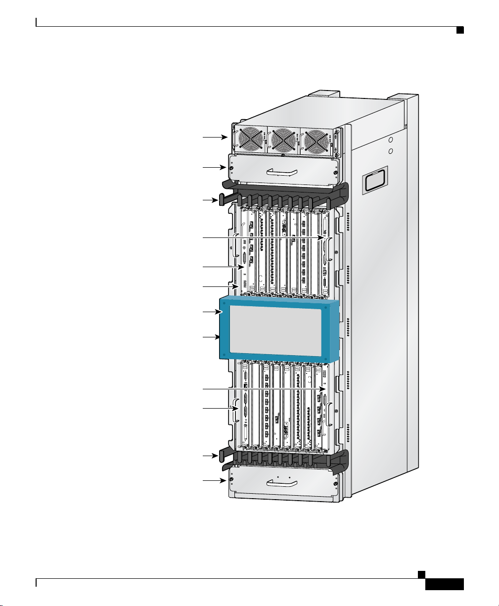
All router models contain the following major components (Figure 1-1):
• Power shelf and power supplies—Three AC or DC power entry modules
(PEMs) provide power to the router. See the
section on page 1-4 for additional information.
• Upper blower module—Supplies cooling air to the upper half of the router so
it does not overheat. See the
“Blower Module” section on page 1-44 for
additional information.
• Upper and lower cable management brackets—Used to neatly route line card
cables. See the
“Upper and Lower Cable Management Brackets” section on
page 1-43 for additional information.
• Upper Line card and Route Processor card cage—Has 8 user-configurable
slots that support a combination of line cards, a route processor (RP), and an
alarm card. See the
“Alarm Card, Line Card, and Rout Processor Overview”
section on page 1-21 for additional information.
“AC and DC Power Subsystems”
1-2
• Switch fabric card cage—Located behind the air filter door, this card cage
contains 5 slots for the switch fabric card set. The switch fabric card set is
made up of 3 switch fabric cards (SFCs) and 2 clock scheduler cards (CSCs).
See the
“Switch Fabric Overview” section on page 1-19 for additional
information.
• Lower Line card and Route Processor card cage—Has 8 user-configurable
slots that support a combination of line cards, a redundant route processor
(RP), and an alarm card. See the
“Alarm Card, Line Card, and Rout Processor
Overview” section on page 1-21 for additional information.
• Lower blower module—Supplies cooling air to the lower half of the router so
it does not overheat. See the
“Blower Module” section on page 1-44 for
additional information.
• Chassis backplane (not shown)—Distributes power to card cages and to the
blower modules.
Cisco 12016, Cisco 12416, and Cisco 12816 Router Installation and Configuration Guide
OL-11495-01
Page 29
Chapter 1 Product Overview
Figure 1-1 Cisco 12016 Series Router Components—Front View
Power shelf and
power supplies
Upper blower
module
Physical and Functional Description of Router
P
W
R
O
K
F
A
U
L
T
T
E
M
P
I
L
I
M
P
W
R
O
K
F
A
U
L
T
T
E
M
P
I
L
I
M
P
W
R
O
K
F
A
U
L
T
T
E
M
P
I
L
I
M
Upper cable
management
bracket
RP
Alarm card
Upper card cage
Air filter door
Switch fabric
card cage
(behind filter door)
Alarm card
Lower card cage
Lower cable
management
bracket
Lower blower
module
DOWN
LOOP RA LA
DOWN
LOOP RA LA
CDHNT CD
CDHNT CD
TX
TX
0
0
RX
RX
0
TX
TX
1
1
RX
RX
ACTIVE
CARRIER
TX
TX
R
X PKT
2
2
RX
RX
TX
TX
1
3
A
C
3
T
I
V
CR
RX
ITICAL
MAJOR
ACTIVE
TX
CARRIER
MINOR
RX PKT
4
RX
TX
2
5
RX
A
CO
/LT
ACTI
VE
CARRIER
RX PKT
ALARM
3
ACTIVE
CARRIER
RX PKT
E
N
A
B
L
F
E
A
D
IL
ENABLED
FAIL
0
Q OC-3/STM-POS
CSC
1
6DS3–SMB P
0
1
SFC
ALARM
2
/
H
/
F
ROUTE PROCESSOR
RJ-45
MII
RX
TX
COLL
INK
L
LE
SO
ON
C
AUX
RESET
LOT-1
S
SLOT-0
EJECT
0
E
C
A
RX
R
R
I
R
E
X
R
P
K
T
TX
ACTIVE
4
CARRIER
RX CEL
RX
L
TX
5
RX
TX
6
RX
TX
7
RX
TX
8
RX
TX
9
RX
TX
10
RX
TX
11
OC-48/STM-16-SCPOS
RX
12DS3–SMB P
OC-12/STM-4 ATM
/
H
/
F
FAST ETERNET
OC-12/STM-4 ATM
OC-48/STM-16-SCPOS
RX CELL
CARRIER
TIVE
AC
T
K
P
R
X
E
R
I
R
R
A
C
E
0
V
I
T
C
A
EJECT
SLOT-0
SLOT-1
RESET
AU
X
C
ON
SO
LE
LINK
CO
TX
LL
RX
MII
RJ-45
FAST ETERNET
ROUTE PROCESSOR
F
F
/
/
H
H
/
/
2
ALARM
SFC
1
0
6DS3–SMB P
12DS3–SMB P
SC
1
RX
C
Q OC-3/STM-POS
0
11
TX
FAIL
LED
ENAB
RX
10
TX
IL
D
A
E
F
L
B
A
N
RX
E
9
TX
KT
RX
RX P
8
CARRIER
ACTIVE
TX
RX
3
7
TX
ALARM
RX
KT
R
RX P
6
CARRIE
TX
ACTIVE
RX
ACO/LT
RX
5
5
2
TX
TX
RX
RX
4
4
RX PKT
MINOR
ARRIER
TX
C
TX
MAJOR
ACTIVE
RX
CRITICAL
RX
3
3
1
TX
TX
RX
RX
2
KT
2
RX P
TX
TX
CARRIER
ACTIVE
RX
RX
1
1
TX
TX
0
RX
RX
0
0
TX
TX
CDHNT CD
CDHNT CD
LOOP RA LA
DOWN
LOOP RA LA
DOWN
26194
OL-11495-01
Cisco 12016, Cisco 12416, and Cisco 12816 Router Installation and Configuration Guide
1-3
Page 30

Physical and Functional Description of Router
AC and DC Power Subsystems
A router ships with either an AC or DC powered system. Source power connects
to the power shelf at the back of the chassis which route power to the power
supplies, also referred to as power entry modules (PEMs).
Standard AC Power Shelf
The standard AC-input power subsystem consists of a single-level AC-input
power shelf that house three (2000
AC power supplies which supply full redundant power to the router.
shows the standard power shelf housing original series 2000 W power supplies.
The power supplies participate in an N+1 redundant current-sharing scheme that
is divided among all three power supplies. If one power supply fails, the system
can continue to operate temporarily, (depending on your system configuration)
with the remaining two power supplies. Failed power supplies should be replaced
as soon as possible to ensure full redundancy.
Chapter 1 Product Overview
W original series or 2400 W enhanced series)
Figure 1-2
1-4
Caution To ensure that the chassis configuration complies with the required power
budgets, use the on-line power calculator. Failure to properly verify the
configuration may result in an unpredictable state if one of the power units fails.
Contact your local sales representative for assistance.
Cisco 12016, Cisco 12416, and Cisco 12816 Router Installation and Configuration Guide
OL-11495-01
Page 31

Chapter 1 Product Overview
Figure 1-2 Standard AC-Input Power Subsystem —2000 W
Caution A router equipped with the standard AC power subsystem must be operated with
three power supplies installed in the power shelf at all times for electromagnetic
compatibility (EMC).
Physical and Functional Description of Router
P
W
R
O
K
F
A
U
L
T
T
E
M
P
I L
IM
P
W
R
O
K
FA
U
L
T
T
EM
P
I L
IM
PW
R
O
K
F
A
U
LT
T
E
M
P
I
LI
M
26198
OL-11495-01
Cisco 12016, Cisco 12416, and Cisco 12816 Router Installation and Configuration Guide
1-5
Page 32

Physical and Functional Description of Router
AC power to the router is provided through power cords connected from AC
power outlets to connectors on back of the power shelf as shown in
Figure 1-3 Standard Power Shelf AC-Input Connections
Chapter 1 Product Overview
Figure 1-3.
Power cord
retention clip
26199
1-6
Cisco 12016, Cisco 12416, and Cisco 12816 Router Installation and Configuration Guide
OL-11495-01
Page 33

Chapter 1 Product Overview
Optional AC Power Shelf
The power subsystem consists of a double-level AC-input power shelf with bays
for 4 AC-input power supplies.
original series 2000 W power supplies. It attaches to the top of the router chassis
and is secured to the chassis the same way as the standard AC-input power shelf.
Note A router equipped with the optional AC-input power subsystem stands 77.5 inches
(196.85 cm) tall and does not fit in a standard 7-foot (2.1 m) rack.
The 4 power supplies in the optional power shelf participate in an N+2 redundant
current-sharing scheme in which current sharing is divided among all 4 power
supplies. Up to two power supplies can fail and the system can continue to operate
temporarily, (depending on your system configuration) using the remaining two
power supplies. Failed supplies should be replaced as soon as possible to ensure
full redundancy.
Caution To ensure that the chassis configuration complies with the required power
budgets, use the on-line power calculator. Failure to properly verify the
configuration may result in an unpredictable state if one of the power units fails.
Contact your local sales representative for assistance.
Physical and Functional Description of Router
Figure 1-4 shows the optional power shelf housing
OL-11495-01
Cisco 12016, Cisco 12416, and Cisco 12816 Router Installation and Configuration Guide
1-7
Page 34

Physical and Functional Description of Router
Figure 1-4 Optional AC-Input Power Subsystem—2000 W
Caution A router equipped with the optional AC power subsystem must be operated with
4 power supplies installed in the power shelf at all times for electromagnetic
compatibility (EMC).
Chapter 1 Product Overview
PW
R
O
K
F
A
U
L
T
T
E
M
P
I
LI
M
P
W
R
O
K
F
A
U
L
T
T
EM
P
I L
IM
PW
R
O
K
F
AU
LT
T
E
M
P
I LIM
P
W
R
O
K
F
A
U
LT
T
E
M
P
I L
IM
27837
1-8
Cisco 12016, Cisco 12416, and Cisco 12816 Router Installation and Configuration Guide
OL-11495-01
Page 35

Chapter 1 Product Overview
AC power to the router is provided through power cords connected from AC
power outlets to the connectors on the back of the power shelf as shown in
Figure 1-5.
Figure 1-5 Optional Power Shelf AC-Input Connections
Physical and Functional Description of Router
Power cords
OL-11495-01
27838
Cisco 12016, Cisco 12416, and Cisco 12816 Router Installation and Configuration Guide
1-9
Page 36

Physical and Functional Description of Router
AC Power Supplies
Each AC PEM converts 200 to 240 VAC into -48 VDC, which is distributed
through the chassis backplane to all cards, RPs, and the blower modules.
Figure 1-6 identifies the components of a 2000 W AC power supply.
Figure 1-6 2000 W AC Power Supply Components
Handle
Chapter 1 Product Overview
PWR OK
PW
R
OK
FA
U
LT
T
EM
P
I L
IM
FAULT
TEMP
I LIM
1-10
Ejector lever
26200
Cisco 12016, Cisco 12416, and Cisco 12816 Router Installation and Configuration Guide
OL-11495-01
Page 37

Chapter 1 Product Overview
Figure 1-7 identifies the components of a 2500 W AC power supply.
Figure 1-7 2500 W AC Power Supply Components
Physical and Functional Description of Router
1
2
Pwr Ok
Fault
Temp
OC
129495
OL-11495-01
Pwr Ok
Fault
Temp
OC
1 Ejector handle 2 Captive screw
The status LEDs on an AC PEM provide information about the current operational
status of the power supply:
• PWR OK (green)—Indicates that the power supply module is operating
normally.
• FAULT (yellow)—Indicates that a fault is detected within the PEM.
• TEMP (yellow)—Indicates the PEM is in an overtemperature condition and
shutdown has occurred.
Cisco 12016, Cisco 12416, and Cisco 12816 Router Installation and Configuration Guide
1-11
Page 38

Physical and Functional Description of Router
• ILMI (yellow)—Indicates the PEM is operating in a current-limiting
condition.
For additional information about troubleshooting AC PEMs, see the
“Troubleshooting the AC-Input Power Subsystem” section on page 5-6.
DC Power Shelf
A DC-input power subsystem consists of a DC-input power shelf that houses 4
(2000
W or 2400 W) DC PEMs that provide full redundant power to the router.
Figure 1-8 shows a DC-input power shelf housing original series 2000 W power
supplies.
The Cisco 12416 and 12816 DC powered systems (part numbers GSR16/320-DC
and GSR16/320-DC) are equipped with 4 PEMs. The chassis is electrically
divided between the PEMS. These sections are referred to as power zones and are
labeled accordingly:
• Two PEMs power the upper card cage (Zone 1)
• Two PEMs power the lower card cage (Zone 2)
Each zone provides power to one blower, one alarm card, line cards and route
processor cards.
Zone 2 also supplies power to all switch fabric cards. The result is that there is
less power available for line cards in Zone 2, limiting the number of high-powered
line cards that can be configured in the lower cage.
Chapter 1 Product Overview
1-12
Caution To ensure that the chassis configuration complies with the required power
budgets, contact your sales representative to provide you with the required power
calculator. Failure to properly verify the configuration may result in an
unpredictable state if one of the power units fails.
Contact your local sales representative for assistance.
In the DC-input power configuration:
• Modules A1 and B1 provide redundant power for system load zone 1 (the
upper blower module and the upper card cage).
• Modules A2 and B2 provide redundant power for system load zone 2 (the
switch fabric card cage, the lower card cage, and the lower blower module).
Cisco 12016, Cisco 12416, and Cisco 12816 Router Installation and Configuration Guide
OL-11495-01
Page 39

Chapter 1 Product Overview
Figure 1-8 DC-Input Power Shelf—2000 Watts
Physical and Functional Description of Router
PWR OK
FAULT
TEMP
PWR OK
FAULT
TEMP
PWR OK
FAULT
TEMP
PWR OK
FAULT
TEMP
26201
Caution A router configured for source DC operation must be operated with 4 DC-input
PEMs installed at all times for electromagnetic compatibility (EMC).
Note DC PEMs support online insertion and removal (OIR) which means that you can
remove and replace one PEM in each load zone (A1 or B1; A2 or B2) while the
system remains powered on.
DC power to the router is provided from cables from a DC power source that are
connected to threaded terminal studs on the back of the DC-input power shelf as
shown in
Figure 1-9.
OL-11495-01
Cisco 12016, Cisco 12416, and Cisco 12816 Router Installation and Configuration Guide
1-13
Page 40

Physical and Functional Description of Router
Figure 1-9 DC-Input Power Shelf Connections
A1-
A1+
A2-
A2+ B2+
B2-
B1
B1- Ground
B1+
Chapter 1 Product Overview
1-14
27964
Cover with slotted screw hole;
fastens to standoff in middle of
cable connection area
Cisco 12016, Cisco 12416, and Cisco 12816 Router Installation and Configuration Guide
OL-11495-01
Page 41

Chapter 1 Product Overview
DC Power Supplies
Each DC PEM operates from a nominal source DC voltage of –48 to –60 VDC
and requires a dedicated 60
Figure 1-10 identifies the components of a 2000 W DC power supply.
Figure 1-10 20 0 0 W D C Power Supply Comp one nts
Handle
amp service.
LEDs
PWR OK
FAULT
TEMP
Physical and Functional Description of Router
PWR OK
FAULT
TEMP
OL-11495-01
Circuit breaker
Ejector lever
Captive screw
26203
Cisco 12016, Cisco 12416, and Cisco 12816 Router Installation and Configuration Guide
1-15
Page 42

Physical and Functional Description of Router
Figure 1-11 identifies the components of a 2400 W DC power supply.
Figure 1-11 2400 W DC Power Supply Components
Chapter 1 Product Overview
2
1
3
PWR OK
FAULT
TEMP
OC
1-16
4
PWR OK FAULT TEMP OC
129494
1 Handle 3 Ejector lever
2 Fan 4 Power switch
The status LEDs on a DC PEM provide information about the current operational
status of the power supply:
• PWR OK (green)—Indicates that the power supply module is operating
normally.
• FAULT (yellow)—Indicates that a fault is detected within the PEM.
• TEMP (yellow)—Indicates the PEM is in an overtemperature condition and
shutdown has occurred.
Cisco 12016, Cisco 12416, and Cisco 12816 Router Installation and Configuration Guide
OL-11495-01
Page 43

Chapter 1 Product Overview
For additional information about troubleshooting DC PEMs, see the
“Troubleshooting the DC-Input Power Subsystem” section on page 5-10.
Chassis Card Cages
There are three integral card cages in the chassis: the upper card cage, the lower
card cage, and the switch fabric card cage (see
Upper Card Cage
The upper card cage has eight user-configurable slots that support a combination
of line cards, an alarm card, and an RP.
• Alarm—The far left slot is a dedicated slot for an alarm card.
• Slots 0 through 6—Can be populated with any line cards supported by the
router.
• Slot 7—The far right slot is reserved for the RP.
Chassis Card Cages
Figure 1-1).
OL-11495-01
Cisco 12016, Cisco 12416, and Cisco 12816 Router Installation and Configuration Guide
1-17
Page 44

Chassis Card Cages
Lower Card Cage
The lower card cage also has eight user-configurable slots that support additional
line cards, an alarm card, and an optional, redundant RP.
Note The lower card cage is an inverted, or head-down, copy of the upper card cage,
which means that cards are installed in an inverted or head-down orientation. The
orientation of the slots is opposite that of the upper card cage.
• Slot 8—The far left slot is reserved for an optional redundant RP.
• Slots 9 through 15—Can be populated with any line cards supported by the
• Alarm—The far right slot is a dedicated slot for an alarm card.
Chapter 1 Product Overview
Note This slot may be used for a line card if you are not using an redundant
RP.
router.
Switch Fabric Card Cage
The router ships from the factory with 2 CSCs and 3 SFCs installed in five of the
eight slots in the switch fabric card cage.
• The 2 CSCs are installed in slot 0 (CSC0) or slot 1 (CSC1)
• The 3 SFCs are installed in slot 2 (SFC0), slot 3 (SFC1), and slot 4 (SFC2).
• Three non-working slots with no backplane connectors. These non-working
slots are not labeled, but there is a blank filler panel installed in the far left
slot to help maintain proper air flow through the chassis.
Caution Do not remove the blank filler panel unless instructed to do so by a Cisco support
representative.
Cisco 12016, Cisco 12416, and Cisco 12816 Router Installation and Configuration Guide
1-18
OL-11495-01
Page 45

Chapter 1 Product Overview
Switch Fabric Overview
The switch fabric provides synchronized gigabit-speed connections between line
cards and the RP. The switch fabric card cage is located behind the air filter door
and consists of 2 clock and scheduler cards (CSCs) and 3 switch fabric cards
(SFCs). One CSC and the 3 SFCs are the active switch fabric; the second CSC
provides redundancy for the other 4 cards.
Note 10-Gbps and 40-Gbps switch fabrics do not operate in 1/4-bandwidth mode as
they did in some earlier models of the Cisco 12000 series routers. You must have
at least one CSC and three SFCs for the system to function. You can add an
additional CSC for redundancy.
The combination of CSCs and SFCs make up the 2.5-Gbps, 10-Gbps, or 40-Gbps
per-slot switch fabric. Routers are identified by the switch fabrics they use:
• Cisco 12010: 2.5-Gbps switch fabric
• Cisco 12410: 10-Gbps switch fabric
• Cisco 12810: 40-Gbps switch fabric
Switch Fabric Overview
Each SFC or CSC provides a 2.5-Gbps, 10-Gbps, or 40-Gbps full-duplex
connection to each line card in the system. For example, in a Cisco
with 16 line cards, each with 2 x 10
switching bandwidth is 16x 20 Gbps = 320 Gbps.
Note The Cisco 12000 series router supports online insertion and removal (OIR),
allowing you to remove and replace a card while the router remains powered on.
Switch Fabric Card Functionality
The core of the router is a crossbar switch fabric that provides synchronized
connections between the line cards and the RP. The switch fabric consists of 2
clock scheduler cards (CSCs) and 3 switch fabric cards (SFCs) installed in the
switch fabric card cage. One CSC and the three SFCs are the active switch fabric;
the second CSC provides redundancy for the other 4 cards.
Cisco 12016, Cisco 12416, and Cisco 12816 Router Installation and Configuration Guide
OL-11495-01
12416 router
Gbps capacity (full duplex), the system
1-19
Page 46

Switch Fabric Overview
The router also ships with a blank switch fabric card installed in the far left
(non-working) slot of the switch fabric card cage. The blank filler panel balances
the air flow through the switch fabric card cage which helps maintain proper air
flow through the chassis.
Caution Do not remove the blank filler panel unless instructed to do so by a Cisco support
representative.
Clock Scheduler Cards
Clock scheduler cards provide the following functionality:
• Scheduler—Handles all scheduling requests from the line cards for access to
the switch fabric.
• System clock—Supplies the synchronizing signal to all SFCs, line cards, and
the RP. The system clock synchronizes data transfers between line cards or
between line cards and the RP through the switch fabric.
• Switch fabric—Carries the user traffic between line cards or between the RP
and a line card. The switch fabric on the CSC is identical to the switch fabric
on the SFC.
Chapter 1 Product Overview
The second CSC provides redundancy for the data path, scheduler, and reference
clock. Traffic between the line cards and the switch fabric is monitored constantly.
If the system detects a loss of synchronization (LOS), it automatically activates
the data paths on the redundant CSC so data flows across the redundant paths. The
switch to the redundant CSC occurs within The switch to the redundant CSC
occurs within sub-seconds (the actual switch time depends on your configuration
and its scale).
Switch Fabric Cards
The switch fabric cards augment the traffic capacity of the router. SFCs contain
switch fabric circuitry that can only carry user traffic between line cards or
between the RP and the line cards. SFCs receive all scheduling information and
the system clock signal from the CSCs.
Cisco 12016, Cisco 12416, and Cisco 12816 Router Installation and Configuration Guide
1-20
OL-11495-01
Page 47

Chapter 1 Product Overview
Alarm Card, Line Card, and Rout Processor Overview
Alarm Card, Line Card, and Rout Processor Overview
This section provides general information about alarm cards, line cards and types
of route processors installed in the router.
Note The Cisco 12000 series router supports online insertion and removal (OIR),
allowing you to remove and replace a card while the router remains powered on.
Alarm Cards
The router is equipped with 2 alarm cards:
• One alarm card occupies the dedicated far left slot of the upper card cage.
• The other alarm card occupies the dedicated far right slot of the lower card
cage.
The alarm card slots differ from the rest of the card cage slots in that it is labeled
as an “alarm” card slot, is physically narrower than the other slots, and has a
different backplane connector.
OL-11495-01
Cisco 12016, Cisco 12416, and Cisco 12816 Router Installation and Configuration Guide
1-21
Page 48

Alarm Card, Line Card, and Rout Processor Overview
Some of the functions that the alarm cards provide are:
• Supplies +5 VDC to the MBus modules on router components (see AC and
DC Power Subsystems, page 1-4).
• Displays alarm severity levels (critical, major, and minor) detected by the
system through the MBus.
• Provides connections for an external alarm system.
• Displays the status of the alarm cards, clock scheduler cards, and switch
fabric cards.
The following components and LEDs are on the front panel of the alarm card
(
Figure 1-12):
• Critical, Major, and Minor LEDs that identify system level alarm conditions.
• A switch to shut off an audio alarm.
• Cable connection for an external alarm (labeled Alarm)
• Alarm card LEDs:
–
ENABLED (green)—The alarm card is operational and functioning
properly.
Chapter 1 Product Overview
1-22
–
FAIL (yellow)—The alarm card in that slot is faulty.
• A pair of status LEDs that correspond to each of the 5 card slots in the switch
fabric card cage (2 CSCs and 3 SFCs):
–
ENABLED (green)
On—The card installed in that slot is operational and functioning
properly.
Off—Either the slot is empty or the card installed in that slot is faulty.
–
FAIL (yellow)—The card in that slot is faulty.
Cisco 12016, Cisco 12416, and Cisco 12816 Router Installation and Configuration Guide
OL-11495-01
Page 49

Chapter 1 Product Overview
Figure 1-12 Alarm Card Components and LEDs
Alarm Card, Line Card, and Rout Processor Overview
Line Cards
CSC
FAIL
ENABLED
FAIL
ENABLED
1
0
Critical, major, and
Handle
CRITICAL
MAJOR
minor alarm LEDs
MAJOR
CRITICAL
MINOR
MINOR
ACO/LT
Audio alarm
cutoff switch
Pin 25
ALARM
Pin 1
CSC
FAIL
ENABLED
ENABLED
SFC
FAIL
1
0
1
2
0
ALARM
Clock and scheduler card
and switch fabric card LEDs
Up to 15 Cisco 12000 series line cards can be installed in the routers upper and
lower card cages to support a variety of physical network media. Ports and
connectors on the line card front panels provide interfaces for external
connections. Line cards communicate with the RP and exchange packet data with
each other through the switch fabric cards.
SFC
2
1
0
26867
OL-11495-01
Caution Any unoccupied card slot in the upper and lower card cages must have a blank
filler panel installed to meet electromagnetic compatibility (EMC) requirements
and to ensure proper air flow through the chassis. Also, if the front panel of a line
card does not completely fill the card slot opening, a narrow card filler panel must
be installed to meet the EMC requirements.
A cable management bracket on the front panel of each line card helps to organize
the interface cables connected to that line card.
Cisco 12016, Cisco 12416, and Cisco 12816 Router Installation and Configuration Guide
1-23
Page 50

Alarm Card, Line Card, and Rout Processor Overview
Route Processor Selection
Two types of RPs are available: a Gigabit Route Processor (GRP) or a
Performance Route Processor (PRP). The GRP is the route processor that shipped
with earlier Cisco 12000 series routers; the PRP is the route processor shipping
with all current Cisco 12000 series routers. You cannot mix GRPs with PRPs. If
you install a redundant RP, it must be the same type as the primary RP.
Note This publication uses the term route processor (RP) to indicate either a Gigabit
Route Processor (GRP) or a Performance Route Processor (PRP) unless otherwise
specified.
Each system includes at least one RP that performs a variety of functions
including the following:
• Downloads the Cisco IOS software to all installed line cards at power-on.
• Processes the network routing protocols and distributes updates to Cisco
Express Forwarding (CEF) tables on the line cards.
• Communicates with the line cards, either through the switch fabric or the
maintenance bus (MBus):
–
The switch fabric connection is the main data path for distributing
routing tables, as well as packets passed between the RP and the line
cards.
Chapter 1 Product Overview
–
The MBus connection allows the RP to download a system bootstrap
image, collect or load diagnostic information, and perform general,
internal system maintenance operations.
Gigabit Route Processor Overview
The GRP uses an IDT R5000 Reduced Instruction Set Computing (RISC) CPU
that runs at an external bus clock speed of 100 MHz and has an internal clock
speed of 200
Figure 1-13 identifies the connectors and LEDs on the GRP front panel.
Cisco 12016, Cisco 12416, and Cisco 12816 Router Installation and Configuration Guide
1-24
MHz.
OL-11495-01
Page 51

Chapter 1 Product Overview
Figure 1-13 Gigabit Route Processor Front Panel
Alarm Card, Line Card, and Rout Processor Overview
EJECT
SLOT-1
RESET
SLOT-0
AUX
CONSOLE
COLL
TX
LINK
RJ-45
RX
MII
GIGABIT ROUTE PROCESSOR
1 432 5 6 7
1 PCMCIA flash card slots, eject buttons, and
5 RJ-45 Ethernet port and data status LEDs
slot LEDs
2 Reset button 6 MII Ethernet connection
3 Auxiliary serial port 7 Alphanumeric message displays
4 Console serial port
GRP PCMCIA Card Slots and Status LEDs
Two PCMCIA card slots (slot 0 and slot 1) provide the GRP with additional flash
memory capacity or other input/output (I/O) device capability.
Caution The GRP only supports +5.2 VDC Type I and Type II devices. It does not support
+3.3 VDC PCMCIA devices.
Status LEDs (Slot-0/Slot-1) indicate when the flash memory card or I/O device in
that slot is accessed. Each slot has an eject button to remove the card from the slot
(
Figure 1-14).
129306
OL-11495-01
Cisco 12016, Cisco 12416, and Cisco 12816 Router Installation and Configuration Guide
1-25
Page 52

Alarm Card, Line Card, and Rout Processor Overview
Figure 1-14 Slot Activity LEDs—Front Panel
EJECT
SLOT-0
SLOT-1
RESET
AUX
Chapter 1 Product Overview
129254
1-26
Cisco 12016, Cisco 12416, and Cisco 12816 Router Installation and Configuration Guide
OL-11495-01
Page 53

Chapter 1 Product Overview
GRP Reset Switch
Caution The reset switch is not a mechanism for resetting the GRP and reloading the
Alarm Card, Line Card, and Rout Processor Overview
Access to the (soft) reset switch is through a small opening in the GRP front panel.
To press the switch, insert a paper clip or similar small pointed object into the
opening (see
Cisco
IOS image. It is intended for software development use only. To prevent
system problems or loss of data, use the reset switch only on the advice of Cisco
service personnel.
Pressing the reset switch causes a nonmaskable interrupt (NMI) and places the
GRP in ROM monitor mode. When the GRP enters ROM monitor mode, its
behavior depends on the setting of the GRP software configuration register. For
example, if the boot field of the software configuration register is set to:
• 0x0—The GRP remains at the ROM monitor prompt (rommon>) and waits for
a user command to boot the system manually.
• 0x1—The system automatically boots the first Cisco IOS image found in
flash memory on the GRP.
For more information on the software configuration register, see the “Configuring
the Software Configuration Register” section on page 4-31.
Figure 1-13 on page 1-25).
OL-11495-01
Cisco 12016, Cisco 12416, and Cisco 12816 Router Installation and Configuration Guide
1-27
Page 54

Alarm Card, Line Card, and Rout Processor Overview
GRP Auxiliary and Console Ports
The auxiliary and console ports on the GRP are EIA/TIA-232 (also known as
RS-232) asynchronous serial ports. These ports connect external devices to
monitor and manage the system.
• The auxiliary port—A (male) plug that provides a data terminal equipment
(DTE) interface. The auxiliary port supports flow control and is often used to
connect a modem, a channel service unit (CSU), or other optional equipment
for Telnet management.
• The console port—A (female) receptacle that provides a data
circuit-terminating equipment (DCE) interface for connecting a console
terminal.
Caution To maintain Class B EMI compliance, use shielded cables when you connect to
the auxiliary and console ports of original GRPs (Part Numbers GRP= and
GRP-B=). An updated version of the GRP-B= board (Rev. F0) does not require
shielded cables for Class B compliance.
Chapter 1 Product Overview
GRP Ethernet Ports and Status LEDs
The GRP has two types of Ethernet connections for Telnet use:
• RJ-45 port—An 8-pin media-dependent interface (MDI) RJ-45 port for either
IEEE 802.3 10BASE-T (10
Ethernet connections.
• MII connector—A 40-pin media-independent interface (MII) that provides
additional flexibility for Ethernet connections. The pinout of this standard
40-pin interface is defined by the IEEE 802.3u standard.
Note The RJ-45 and MII interfaces on the GRP represent two physical
connection options for one Ethernet interface; therefore, you can use
either the RJ-45 connection or the MII connection, but not both
simultaneously.
Cisco 12016, Cisco 12416, and Cisco 12816 Router Installation and Configuration Guide
1-28
Mbps) or IEEE 802.3u 100BASE-TX (100 Mbps)
OL-11495-01
Page 55

Chapter 1 Product Overview
The transmission speed of the Ethernet port is not user-configurable. You set the
speed through an autosensing scheme on the GRP which is determined by the
network that the Ethernet port is connected to. However, even at an autosensed
data transmission rate of 100 Mbps, the Ethernet port can only provide a usable
bandwidth of substantially less than 100 Mbps. You can expect a maximum usable
bandwidth of approximately 20 Mbps when using either the MII or RJ-45
connection.
The following LEDs on the front panel indicate traffic status and port selection
(
Figure 1-15):
• LINK, COLL, TX, RX—Indicate link activity (LINK), collision detection
• MII/RJ-45—Indicates which Ethernet port is selected.
Figure 1-15 Port Activity LEDs—Front Panel
Alarm Card, Line Card, and Rout Processor Overview
(COLL), data transmission (TX), and data reception (RX).
Note These LEDs are only used by the RJ-45 Ethernet connector and are
disabled when the MII Ethernet port is in use.
OL-11495-01
LINK
TX
MII
Cisco 12016, Cisco 12416, and Cisco 12816 Router Installation and Configuration Guide
COLL
RX
RJ-45
H10762
1-29
Page 56

Alarm Card, Line Card, and Rout Processor Overview
GRP Alphanumeric Message Displays
The alphanumeric message displays are organized in two rows of four LED
characters (
Figure 1-16 Alphanumeric Message Displays—Front Panel
PROCESSOR
Figure 1-16).
Chapter 1 Product Overview
Upper alphanumeric
LED display (four digits)
Lower alphanumeric
LED display (four digits)
1-30
H10780
The alphanumeric message displays show router status messages during the boot
process, and after the boot process is complete.
• During the boot process, the message displays are controlled directly by the
MBus module.
• After the boot process, the message displays are controlled by Cisco IOS
software (through the MBus).
The alphanumeric message displays also provide information about different
levels of system operation, including the status of the GRP, router error messages,
and user-defined status and error messages
Note A complete, descriptive list of all system and error messages appears in the Cisco
IOS System Error Messages publication.
Cisco 12016, Cisco 12416, and Cisco 12816 Router Installation and Configuration Guide
OL-11495-01
Page 57

Chapter 1 Product Overview
Alarm Card, Line Card, and Rout Processor Overview
GRP Memory Components
This section describes various types of memory used on the GRP to support router
functions.
and Figure 1-17 shows the location on the GRP board.
Ta b l e 1-1 GRP Memory Components
Ty pe Size Quantity Description Location
DRAM 1281 or
256 MB
SRAM 512 KB (fixed) — Secondary CPU cache memory
NVRAM 512 KB (fixed) — System configuration files, register
Flash memory 8 MB SIMM 1 Cisco IOS software images and other
Flash memory
20 MB1 1 or 2 Cisco IOS software images, system
card
PCMCIA
Flash boot
2
512 KB 1 Flash EPROM for the ROM monitor
ROM
1. Default shipping configuration.
2. Type I or Type II PCMCIA cards can be used in either slot.
Table 1-1 provides a quick reference of the different types of memory,
1 or 2 Uses 64 MB or 128 MB DIMMs
(based on DRAM configuration) for
main Cisco
IOS software functions
U39 (bank 1)
U42 (bank 2)
—
functions
—
settings, and logs
U17
user-defined files
Slots 0 and 1
configuration files, and other
user-defined files on one or two flash
memory cards
—
program boot image
OL-11495-01
Cisco 12016, Cisco 12416, and Cisco 12816 Router Installation and Configuration Guide
1-31
Page 58

Alarm Card, Line Card, and Rout Processor Overview
Figure 1-17 GRP Memory Locations
Chapter 1 Product Overview
Bank 2
DRAM DIMMs
Bank 1
PCMCIA slot-0
and slot-1
U17
T
C
JE
E
S
LO
S
LO
-1
T
-0
T
U42
U39
T
E
S
E
R
AUX
Flash
SIMM
LL
J-45
O
X
R
C
R
II
K
TX
M
LIN
GIGABIT ROUTE PROCESSOR
129255
1-32
Cisco 12016, Cisco 12416, and Cisco 12816 Router Installation and Configuration Guide
OL-11495-01
Page 59

Chapter 1 Product Overview
GRP DRAM
Alarm Card, Line Card, and Rout Processor Overview
The GRP uses Extended Data-Out (EDO) Dynamic Random Access Memory
(DRAM) to store routing tables, protocols, network accounting applications, and
to run Cisco
Table 1-2 lists the DRAM configurations for the GRP.
Ta b l e 1-2 GRP DRAM Configurations
Total DRAM Part Number DRAM Sockets Number of DIMMs
128 MB
128 MB MEM-GRP/LC-128(=) U39 (bank 1) One 128 MB
256 MB MEM-GRP/LC-256(=) U39 (bank 1)
1. Default shipping configuration.
IOS software.
1
MEM-GRP/LC-64(=) U39 (bank 1)
U42 (bank 2)
U42 (bank 2)
Two 64 MB
Two 128 MB
Caution DRAM DIMMs must be 3.3-volt, 60-nanosecond devices only. Do not attempt to
GRP SRAM
GRP NVRAM
OL-11495-01
install other devices in the DIMM sockets. To prevent memory problems, use the
Cisco approved memory products listed in Table 1-2.
Static Random Access Memory (SRAM) provides 512 KB of secondary CPU
cache memory. Its principal function is to act as a staging area for routing table
updates, and for information sent to and received from the line cards. SRAM is
not user-configurable and cannot be upgraded in the field.
Nonvolatile Random Access Memory (NVRAM) provides 512 KB of memory for
system configuration files, software register settings, and environmental
monitoring logs. Built-in lithium batteries retain the contents of NVRAM for a
minimum of 5 years. NVRAM is not user configurable and cannot be upgraded in
the field.
Cisco 12016, Cisco 12416, and Cisco 12816 Router Installation and Configuration Guide
1-33
Page 60

Alarm Card, Line Card, and Rout Processor Overview
GRP Flash Memory
Use flash memory to store multiple Cisco IOS software and microcode images
that you can use to operate the router. You can download new images to flash
memory over the network (or from a local server) to replace an existing image, or
to add it as an additional image. The router can be booted (manually or
automatically) from any of the stored images in flash memory.
Flash memory also functions as a Trivial File Transfer Protocol (TFTP) server that
allows other servers to boot remotely from the stored images, or to copy them into
their own flash memory.
The system uses two types of flash memory:
• Onboard flash memory (called bootflash) —Contains the Cisco IOS boot
image.
• 20 MB Type II PCMCIA flash memory cards (MEM-GRP-FL20=)—Contain
the Cisco IOS software images.
Performance Route Processor Overview
Chapter 1 Product Overview
The performance route processor (PRP) uses a Motorola PowerPC 7450 CPU that
runs at an external bus clock speed of 133 MHz and has an internal clock speed
of 667 MHz.
Figure 1-18 identifies the slots, ports, and LEDs on the PRP front panel.
Figure 1-18 Performance Route Processor Front Panel
EJECT
ETH 1ETH 0 AUX
SLOT-1
SLOT-0
PRIMARY
RX
TX
PRIMARY
EN
LINK
EN
LINK
CONSOLE
RX
TX
RESET
PERFORMANCE ROUTE PROCESSOR 1 (PRP-1)
1 3 4 52 6
1 PCMCIA flash disk slots (shown with cover in
4 Console serial port
place) and slot LEDs
2 RJ-45 Ethernet ports and data status LEDs 5 Reset button
3 Auxiliary serial port 6 Alphanumeric message displays
Cisco 12016, Cisco 12416, and Cisco 12816 Router Installation and Configuration Guide
1-34
129307
OL-11495-01
Page 61

Chapter 1 Product Overview
PRP PCMCIA Card Slots and Status LEDs
Two PCMCIA card slots (slot 0 and slot 1) provide the PRP with additional flash
memory capacity. All combinations of different flash devices are supported by the
PRP. You can use ATA flash disks, Type 1 or Type 2 linear flash memory cards,
or a combination of the two.
Note The PRP only supports +5.2 VDC flash memory devices. It does not support
+3.3 VDC PCMCIA devices.
Status LEDs (Slot-0 / Slot-1) indicate when the flash memory card in that slot is
accessed (see
cover) to remove a flash card from the slot.
Figure 1-18). Each slot has an eject button (located behind the
PRP Ethernet Ports and Status LEDs
The PRP has two 8-pin media-dependent interface (MDI) RJ-45 ports for either
IEEE 802.3 10BASE-T (10
Ethernet connections. These ports are labeled ETH 0 and ETH 1.
Alarm Card, Line Card, and Rout Processor Overview
Mbps) or IEEE 802.3u 100BASE-TX (100 Mbps)
OL-11495-01
The transmission speed of the Ethernet port is not user-configurable. You set the
speed through an autosensing scheme on the PRP which is determined by the
network that the Ethernet port is connected to. However, even at an autosensed
data transmission rate of 100 Mbps, the Ethernet port can only provide a usable
bandwidth of substantially less than 100 Mbps. You can expect a maximum usable
bandwidth of approximately 20 Mbps when using an Ethernet connection.
Cisco 12016, Cisco 12416, and Cisco 12816 Router Installation and Configuration Guide
1-35
Page 62

Alarm Card, Line Card, and Rout Processor Overview
The following LEDs on the front panel indicate traffic status and port selection
(
Figure 1-19):
• LINK, EN, TX, RX—Indicate link activity (LINK), port enabled (EN), data
transmission (TX), and data reception (RX).
• PRIMARY—Indicates which Ethernet port is selected (ETH 0 or ETH 1).
Note Because both ports are supported on the PRP, ETH 0 is always on. ETH 1
lights when it is selected.
Figure 1-19 Port Activity LEDs—Partial Front Panel
Chapter 1 Product Overview
ETH 1ETH 0
SLOT-1
SLOT-0
PRIMARY
PRP Auxiliary and Console Ports
The auxiliary and console ports on the PRP are EIA/TIA-232 (also known as
RS-232) asynchronous serial ports. These ports connect external devices to
monitor and manage the system.
• The auxiliary port—A (male) plug that provides a data terminal equipment
(DTE) interface. The auxiliary port supports flow control and is often used to
connect a modem, a channel service unit (CSU), or other optional equipment
for Telnet management.
• The console port—A (female) receptacle that provides a data
circuit-terminating equipment (DCE) interface for connecting a console
terminal.
EN
LINK
RX
TX
PRIMARY
EN
LINK
RX
TX
70693
1-36
Cisco 12016, Cisco 12416, and Cisco 12816 Router Installation and Configuration Guide
OL-11495-01
Page 63

Chapter 1 Product Overview
PRP Reset Switch
Caution The reset switch is not a mechanism for resetting the PRP and reloading the
Alarm Card, Line Card, and Rout Processor Overview
Access to the (soft) reset switch is through a small opening in the PRP front panel
(see
Figure 1-18). To press the switch, insert a paper clip or similar small pointed
object into the opening.
Cisco
IOS image. It is intended for software development use only. To prevent
system problems or loss of data, use the reset switch only on the advice of Cisco
service personnel.
Pressing the reset switch causes a nonmaskable interrupt (NMI) and places the
PRP in ROM monitor mode. When the PRP enters ROM monitor mode, its
behavior depends on the setting of the PRP software configuration register. For
example, if the boot field of the software configuration register is set to:
• 0x0—The PRP remains at the ROM monitor prompt (rommon>) and waits for
a user command to boot the system manually.
• 0x1—The system automatically boots the first Cisco IOS image found in
flash memory on the PRP.
For more information on the software configuration register, see the “Configuring
the Software Configuration Register” section on page 4-31.
OL-11495-01
Cisco 12016, Cisco 12416, and Cisco 12816 Router Installation and Configuration Guide
1-37
Page 64

Alarm Card, Line Card, and Rout Processor Overview
PRP Alphanumeric Message Displays
The alphanumeric message displays are organized in two rows of four LED
characters each (
Figure 1-20 Alphanumeric Message Displays—Partial Front Panel
PROCESSOR
Figure 1-20).
Chapter 1 Product Overview
Upper alphanumeric
LED display (four digits)
Lower alphanumeric
LED display (four digits)
1-38
H10780
The alphanumeric message displays show router status messages during the boot
process, and after the boot process is complete.
• During the boot process, the message displays are controlled directly by the
MBus module.
• After the boot process, the message displays are controlled by Cisco IOS
software (through the MBus).
The alphanumeric message displays also provide information about different
levels of system operation, including the status of the GRP, router error messages,
and user-defined status and error messages
Note A complete, descriptive list of all system and error messages appears in the Cisco
IOS System Error Messages publication.
Cisco 12016, Cisco 12416, and Cisco 12816 Router Installation and Configuration Guide
OL-11495-01
Page 65

Chapter 1 Product Overview
Alarm Card, Line Card, and Rout Processor Overview
PRP Memory Components
This section describes various types of memory used on the PRP to support router
functions.
and Figure 1-21 shows the location on the PRP board.
Ta b l e 1-3 PRP Memory Components
Ty pe Size Quantity Description Location
SDRAM 512 MB1,
1 GB, or 2 GB
SRAM 2 MB (fixed) — Secondary CPU cache memory functions —
NVRAM 2 MB (fixed) — System configuration files, register settings,
Flash
64 MB SIMM 1 Cisco IOS boot image (bootflash), crash
memory
Flash disk
64 MB
1
(PCMCIA)
Flash boot
512 KB 1 Flash EPROM for the ROM monitor program
ROM
1. Default shipping configuration.
Table 1-3 provides a quick reference of the different types of memory,
1 or 2 Uses 512 MB or 1 GB DIMMs (based on
SDRAM configuration) for main Cisco IOS
U15 (bank 1)
U18 (bank 2)
software functions
—
and logs
P3
information, and other user-defined files
1 or 2 Cisco IOS software images, system
configuration files, and other user-defined
files on one or two Flash memory cards
Flash memory
card slot 0 and
slot 1
—
boot image
OL-11495-01
Cisco 12016, Cisco 12416, and Cisco 12816 Router Installation and Configuration Guide
1-39
Page 66

Alarm Card, Line Card, and Rout Processor Overview
Figure 1-21 PRP Memory Locations
Chapter 1 Product Overview
Flash
SIMM
T
C
EJE
PCMCIA slot-1
and slot-2
(behind cover)
U18
P3
SLOT-1
SLOT-0
Bank 2
DRAM DIMMs
Bank 1
U15
ETH 1ETH 0 AUX
RX
TX
EN
EN
Y
Y
R
R
A
A
IM
IM
R
R
P
P
LINK
LINK
CONSOLE
RX
TX
RESET
PERFORMANCE ROUTE PROCESSOR 1 (PRP-1)
129256
1-40
Cisco 12016, Cisco 12416, and Cisco 12816 Router Installation and Configuration Guide
OL-11495-01
Page 67

Chapter 1 Product Overview
PRP SDRAM
Alarm Card, Line Card, and Rout Processor Overview
The PRP uses Error Checking and Correction (ECC) Synchronized Dynamic
Random Access Memory (SDRAM) to store routing tables, protocols, network
accounting applications, and to run Cisco
Table 1-4 lists the DRAM configurations for the PRP. If you are using:
• One DIMM—Bank 1 (U15) must be populated first.
• Two DIMMs—You cannot mix memory sizes; both banks must contain the
same size DIMM.
Ta b l e 1-4 PRP DRAM Configurations
Total
SDRAM
512 MB
Part Number SDRAM Sockets Number of DIMMs
1
???(=) U15 (bank 1)
1 GB ???(=) U15 (bank 1)
2 GB ???(=) U15 (bank 1)
1. Default shipping configuration.
IOS software.
U18 (bank 2)
U18 (bank 2)
U18 (bank 2)
One 512 MB DIMM
or
Two 256 MB DIMMs
One 1 GB DIMM
or
Two 512 MB DIMMs
Two 1 GB DIMMs
Caution DRAM DIMMs must be 3.3-volt, 60-nanosecond devices only. Do not attempt to
PRP SRAM
OL-11495-01
install other devices in the DIMM sockets. To prevent memory problems, use the
Cisco approved memory products listed in Table 1-4.
Static Random Access Memory (SRAM) provides 2 MB of secondary CPU cache
memory. Its principal function is to act as a staging area for routing table updates,
and for information sent to and received from the line cards. SRAM is not
user-configurable and cannot be upgraded in the field.
Cisco 12016, Cisco 12416, and Cisco 12816 Router Installation and Configuration Guide
1-41
Page 68

Alarm Card, Line Card, and Rout Processor Overview
PRP NVRAM
Non-volatile Random Access Memory (NVRAM) provides 2 MB of memory for
system configuration files, software register settings, and environmental
monitoring logs. Built-in lithium batteries retain the contents of NVRAM for a
minimum of 5 years. NVRAM is not user configurable and cannot be upgraded in
the field.
PRP Flash Memory
Use flash memory to store multiple Cisco IOS software and microcode images
that you can use to operate the router. You can download new images to flash
memory over the network (or from a local server) to replace an existing image, or
to add it as an additional image. The router can be booted (manually or
automatically) from any of the stored images in flash memory.
Flash memory also functions as a Trivial File Transfer Protocol (TFTP) server to
allow other servers to boot remotely from the stored images, or to copy them into
their own flash memory.
The system uses two types of flash memory:
Chapter 1 Product Overview
1-42
• Onboard flash memory (called bootflash)—Contains the Cisco IOS boot
image
• Flash memory disks (or cards)—Contain the Cisco IOS software image
Table 1-5 lists supported flash disk sizes and Cisco part numbers.
Ta b l e 1-5 Supported Flash Disk Sizes
Flash Disk Size
2
64 MB
1
Part Number
MEM-12KRP-FD64=
128 MB MEM-12KRP-FD128=
1 GB MEM-12KRP-FD1G=
1. Standard Type 1 and Type 2 linear flash memory cards also are supported,
although they may not have the capacity to meet the configuration
requirements of your system.
2. Default shipping configuration.
Cisco 12016, Cisco 12416, and Cisco 12816 Router Installation and Configuration Guide
OL-11495-01
Page 69

Chapter 1 Product Overview
Alarm Card, Line Card, and Rout Processor Overview
Upper and Lower Cable Management Brackets
Cisco 12010, Cisco 12410, and Cisco 12810 series routers include upper and
lower cable management brackets that work together with individual line card
cable management brackets to organize interface cables entering and exiting the
router (see
Network interface cables to the line cards are fed across the brackets, and then
through the openings to the individual line card cable management bracket. This
system keeps cables out of the way and free of sharp bends.
Caution Excessive bending of interface cables can damage the cables.
Figure 1-1).
OL-11495-01
Cisco 12016, Cisco 12416, and Cisco 12816 Router Installation and Configuration Guide
1-43
Page 70

Blower Module
Blower Module
The router has two blower modules to distribute air within the chassis. One blower
module is located above the upper card cage; the second blower module is located
below the lower card cage (see
Each blower module contains three variable speed fans and a controller card. The
two front cover LEDs provide a visual indication of blower module status
(
Figure 1-22):
Figure 1-22 Blower Module
Chapter 1 Product Overview
Figure 1-1).
LEDs
129308
1-44
• OK (green)—All three fans are operating normally.
• FAIL (red)—The system has detected a fan failure or other fault in the blower
module. The fault can be caused by any of the following:
–
One or more fans are not operating
–
One or more fans are running below speed
–
A controller card fault
The blower modules maintain acceptable operating temperatures for the internal
components by drawing cool air through a replaceable air filter into the switch
fabric card cage and then through the upper and lower card cages.
illustrates the air flow path through the chassis.
Cisco 12016, Cisco 12416, and Cisco 12816 Router Installation and Configuration Guide
Figure 1-23
OL-11495-01
Page 71

Chapter 1 Product Overview
Figure 1-23 Cooling Ai r Fl ow
Blower Module
Power supply shelf
Top blower module
Air filter
Room air
Air exhaust
(Plenum)
Upper card cage
Middle card cage
Lower card cage
(Plenum)
OL-11495-01
Bottom blower module
Front Rear
Air exhaust
26204
To ensure that there is adequate air flow to prevent overheating inside the card
cages keep the front and back of the router unobstructed. We recommend at least
6
inches (15.24 cm) of clearance.
Cisco 12016, Cisco 12416, and Cisco 12816 Router Installation and Configuration Guide
1-45
Page 72

Blower Module
Caution You should inspect and clean the air filter one time per month (more often in dusty
Chapter 1 Product Overview
environments). Do not operate the router without an air filter installed.
The blower module controller card monitors and controls operation of three
variable-speed fans in the blower modules. The variable-speed feature allows
quieter operation by running the fans at below maximum speed, while still
providing adequate cooling to maintain an acceptable operating temperature
inside the card cages.
Two temperature sensors on each line card monitor the internal air temperature in
the card cages:
• When the ambient air temperature is within the normal operating range, the
fans operate at their lowest speed, which is 55 percent of the maximum speed.
• If the air temperature rises inside the card cages the fan speed increases to
provide additional cool air to the cards.
• If the air temperature continues to rise beyond the specified threshold, the
system environmental monitor shuts down all internal power to prevent
equipment damage due to excessive heat.
• If the system detects that one of the three fans within a blower module has
failed, it displays a warning message on the console window. In addition, the
two remaining fans go to full speed to compensate for the loss of the one fan.
If another fan fails, the system shuts down to prevent equipment damage.
For additional troubleshooting information, see the “Blower Module Operation”
section on page 5-38.
1-46
Cisco 12016, Cisco 12416, and Cisco 12816 Router Installation and Configuration Guide
OL-11495-01
Page 73

CHA P TER
2
Preparing for Installation
Before installing your router, consider power and cabling requirements that must
be in place at your installation site, special equipment for installing the router, and
the environmental conditions your installation site must meet to maintain normal
operation. This chapter guides you through the process of preparing for router
installation.
The shipping package for the router is engineered to reduce the chances of product
damage associated with routine material handling experienced during shipment.
• The router should always be transported or stored in its shipping package in
the upright position.
• Keep the router in the shipping container until you have determined the
installation site.
Use the Cisco 12016, Cisco 12416, and Cisco 12816 Router Unpacking
Instructions included with the router to unpack it and inspect all items for
shipping damage. If an item appears damaged, contact a Cisco customer service
representative immediately.
This chapter contains the following installation topics:
OL-11495-01
• Safety Guidelines, page 2-2
• Site Requirement Guidelines, page 2-7
• GRP Port Connection Guidelines, page 2-25
• PRP Port Connection Guidelines, page 2-36
• Alarm Card Connection Guidelines, page 2-45
Cisco 12016, Cisco 12416, and Cisco 12816 Router Installation and Configuration Guide
2-1
Page 74

Safety Guidelines
Safety Guidelines
Before you perform any procedure in this publication, review the safety
guidelines in this section to avoid injuring yourself or damaging the equipment.
In addition, be sure to review the safety warnings listed in the Regulatory
Compliance and Safety Information for Cisco 12000 Series Internet Routers
publication that accompanied your router before you begin router installation.
Note that the information in this section are guidelines and do not include every
potentially hazardous situation. When you install a router, always use common
sense and caution.
Safety with Equipment
• Cisco equipment operates safely when used in accordance with its
specifications and product-usage instructions.
• Never install equipment that appears damaged.
• Do not perform any action that creates a potential hazard to people or makes
the equipment unsafe.
• Never attempt to lift an object that might be too heavy for you to lift by
yourself.
• Do not wear loose clothing, jewelry, or other items that could get caught in
the router.
Chapter 2 Preparing for Installation
2-2
• Keep tools and assembly components away from walk areas.
• Do not work alone if potentially hazardous conditions exist.
• Keep the work area clear and dust-free during and after installation. Do not
allow dirt or debris to enter into any laser-based components.
Cisco 12016, Cisco 12416, and Cisco 12816 Router Installation and Configuration Guide
OL-11495-01
Page 75

Chapter 2 Preparing for Installation
Safety with Electricity
• The installation shall be in compliance with national and local electrical
codes: in the United States, National Fire Protection Association (NFPA) 70,
United States National Electrical Code; in Canada, Canadian Electrical Code,
part I, CSA C22.1; in other countries, International Electrotechnical
Commission (IEC) 60364, part 1 through part 7.
• Before you begin any procedures requiring access to the interior of the router,
locate the emergency power-off switch for the room in which you are
working.
• Disconnect all power source cables before installing or removing a router.
• Never assume that power has been disconnected from a circuit; always check.
• Carefully examine your work area for possible hazards such as moist floors,
ungrounded power extension cables, and missing safety grounds.
• Only a DC power source that complies with the safety extra-low voltage
(SELV) requirements in UL60950, CSA-C22.2 No. 60950, EN60950,
ACATS001, AS/NZS 60950,and IEC60950 can be connected to the line card
chassis DC-input power system.
• A line card chassis configured with the DC-input power system shall have a
readily accessible two-poled disconnect device incorporated in the fixed
wiring.
Safety Guidelines
OL-11495-01
• The line card chassis requires short-circuit (overcurrent) protection to be
provided as part of the building installation.
• If an electrical accident occurs, proceed as follows:
–
Use caution; do not become a victim. Disconnect power to the router.
–
If possible, send another person to get medical aid; otherwise, assess the
condition of the victim and then call for help.
Cisco 12016, Cisco 12416, and Cisco 12816 Router Installation and Configuration Guide
2-3
Page 76

Safety Guidelines
Preventing Electrostatic Discharge Damage
Many router components can be damaged by static electricity. Not exercising the
proper electrostatic discharge (ESD) precautions can result in intermittent or
complete component failures. To minimize the potential for ESD damage, always
use an ESD-preventive antistatic wrist strap (or ankle strap) and ensure that it
makes good skin contact.
Note Check the resistance value of the ESD-preventive strap periodically. The
measurement should be between 1 and 10 megohms.
Before you perform any of the procedures in this guide, attach an ESD-preventive
strap to your wrist and connect the leash to the chassis or to another grounded,
bare metal surface as shown in
Figure 2-1.
Chapter 2 Preparing for Installation
2-4
Cisco 12016, Cisco 12416, and Cisco 12816 Router Installation and Configuration Guide
OL-11495-01
Page 77

Chapter 2 Preparing for Installation
Figure 2-1 Connecting an ESD-Preventive Strap to the Router Chassis
DOWN
LOOP RA LA
DOWN
LOOP RA LA
CDHNT CD
CDHNT CD
TX
TX
0
0
RX
RX
0
TX
TX
1
1
RX
RX
A
C
T
I
V
C
E
A
TX
R
TX
R
R
I
X
E
P
R
2
K
2
T
RX
RX
TX
TX
ESD
connection
socket
O
O
O
O
O
O
O
O
O
O
O
O
O
O
O
O
O
O
O
O
O
O
O
O
O
O
O
O
O
O
O
O
O
O
O
O
O
O
O
O
O
O
O
O
O
O
O
O
O
O
O
O
O
O
O
O
O
O
O
O
O
O
O
O
O
O
O
O
O
O
O
O
O
O
O
O
O
O
O
O
O
O
O
O
O
O
O
O
O
O
O
O
O
O
O
O
O
1
3
A
C
3
T
IV
CRITICAL
RX
MAJOR
A
C
T
TX
I
V
C
MINOR
E
A
R
R
R
4
I
X
E
R
P
K
T
RX
TX
2
5
RX
ACO/LT
A
C
T
I
V
C
E
A
R
R
R
I
X
E
R
P
K
T
ALARM
3
A
C
T
I
V
C
E
A
R
R
R
I
X
E
R
P
K
T
ENABLED
FAIL
ENABLED
FAIL
0
Q OC-3/STM-POS
CSC
1
6DS3–SMB P
0
1
SFC
ALARM
2
/
H
/
F
ROUTE PROCESSOR
RJ-45
MII
RX
TX
COLL
LINK
CONSOLE
X
U
A
RESET
SLOT-1
SLOT-0
EJECT
RX
TX
4
RX
TX
5
RX
TX
6
RX
TX
7
RX
TX
8
RX
TX
9
RX
TX
10
RX
TX
11
RX
12DS3–SMB P
/
H
/
F
FAST ETERNET
0
E
C
A
R
R
IE
R
X
R
P
K
T
A
C
T
IV
C
E
A
R
R
R
I
X
E
C
R
E
L
L
OC-48/STM-16-SCPOS
OC-12/STM-4 ATM
FAST ETERNET
F
/
H
/
OC-12/STM-4 ATM
12DS3–SMB P
RX
OC-48/STM-16-SCPOS
11
TX
RX
10
TX
RX
9
TX
RX
8
TX
RX
7
TX
RX
6
TX
RX
5
L
L
E
R
C
X
IE
R
R
R
A
E
C
IV
T
C
A
TX
RX
4
TX
T
K
P
X
R
IER
RR
RX
A
C
0
IVE
T
3
C
A
TX
RX
2
TX
RX
1
TX
RX
0
TX
CDHNT CD
LOOP RA LA
DOWN
EJECT
SLOT-0
SLOT-1
RESET
A
U
X
CONSOLE
LINK
COLL
TX
RX
MII
RJ-45
ROUTE PROCESSOR
F
/
H
/
2
ALARM
SFC
1
0
6DS3–SMB P
1
CSC
Q OC-3/STM-POS
0
FAIL
ENABLED
FAIL
ENABLED
T
K
P
R
X
IE
R
R
R
A
E
C
V
I
T
C
A
3
ALARM
T
K
P
R
X
IE
R
R
R
A
E
C
V
I
T
C
A
ACO/LT
RX
5
2
TX
RX
T
K
P
R
E
X
I
4
R
R
R
MINOR
A
E
C
V
I
TX
T
C
MAJOR
A
CRITICAL
RX
3
1
TX
RX
T
K
2
P
R
X
IE
R
R
R
TX
A
E
C
IV
T
C
A
RX
1
TX
0
RX
0
TX
CDHNT CD
LOOP RA LA
DOWN
Safety Guidelines
OL-11495-01
26208
Cisco 12016, Cisco 12416, and Cisco 12816 Router Installation and Configuration Guide
2-5
Page 78

Safety Guidelines
Lifting Guidelines
A fully configured router can weigh as much as 275 pounds (lb)
(124.74
systems are not intended to be moved frequently. Before you install the router,
ensure that your site is properly prepared so you can avoid having to move the
router later to accommodate power sources and network connections.
Use the following lifting guidelines to avoid injury to yourself or damage to the
equipment:
• Do not lift equipment alone; have another person help you to lift heavy
• Ensure that your footing is solid; balance the weight of the object between
• Lift the equipment slowly; never move suddenly or twist your body as you
• Keep your back straight and lift with your legs, not your back. When bending
Chapter 2 Preparing for Installation
kilograms (kg)), while an empty chassis weighs 125 lb (56.7 kg). These
equipment.
your feet.
lift.
down to lift equipment, bend at the knees (not at the waist), to reduce the
strain on your lower back muscles.
Caution To prevent equipment damage, never attempt to lift or tilt the router chassis using
the handles on the blower module or on line cards. These handles do not support
the weight of the chassis.
Compliance and Safety Information
The Cisco 12016, Cisco 2416 and Cisco 12816 routers are designed to meet the
regulatory compliance and safety approval requirements. Refer to the Regulatory
Compliance and Safety Information for the Cisco
(Document Number 78-4347-xx) if you require additional compliance
information (see
page -xx for site information).
Cisco 12016, Cisco 12416, and Cisco 12816 Router Installation and Configuration Guide
2-6
“Cisco Technical Support & Documentation Website” section on
12000 Series Router
OL-11495-01
Page 79

Chapter 2 Preparing for Installation
Laser Safety
Some line cards are equipped with ports that can emit hazardous laser radiation
from the aperture when there is no cable connected to the port. This invisible
radiation can cause eye injury if you stare into the port.
Site Requirement Guidelines
Warning
To avoid eye injury, never stare into open line card ports.
Site Requirement Guidelines
This section provides the following site requirement guidelines that you must
consider before installing the router:
• Rack-Mounting Guidelines, page 2-7
• Air Flow Guidelines, page 2-15
• Temperature and Humidity Guidelines, page 2-17
• Power Connection Guidelines, page 2-17
• NEBS Supplemental Unit Bonding and Grounding Guidelines, page 2-22
• Site Wiring Guidelines, page 2-24
Rack-Mounting Guidelines
The router can be mounted in most 2-post, 4-post, or telco-type 19-inch
equipment racks that comply with the Electronics Industries Association (EIA)
standard for equipment racks (EIA-310-D). The rack must have at least two posts
with mounting flanges to mount the router chassis. The distance between the
center lines of the mounting holes on the two mounting posts must be 18.31 inches
± 0.06
inch (46.50 cm ± 0.15 cm). The rack-mounting hardware included with the
router is suitable for most 19-inch equipment racks or telco-style frames.
Figure 2-2 shows examples of typical 2-post, 4-post, and telco-type equipment
racks.
OL-11495-01
Cisco 12016, Cisco 12416, and Cisco 12816 Router Installation and Configuration Guide
2-7
Page 80

Site Requirement Guidelines
Figure 2-2 Equipment Rack Types
a b c
Chapter 2 Preparing for Installation
27959
Enclosed Rack
Open Rack
Cisco 12016, Cisco 12416, and Cisco 12816 Router Installation and Configuration Guide
2-8
Figure 2-2a shows a free-standing, enclosed rack with two mounting posts in the
front. The router should not be installed in this type of enclosed rack, because the
router requires an unobstructed flow of cooling air to maintain acceptable
operating temperatures for its internal components. Installing the router in any
type of enclosed rack—even with the front and back doors removed—could
disrupt the air flow, trap heat next to the chassis, and cause an overtemperature
condition inside the router.
Figure 2-2b shows a free-standing, 4-post open rack with two mounting posts in
the front and two mounting posts in the back. The mounting posts in this type of
rack are often adjustable so that you can position the rack-mounted unit within the
depth of the rack rather than flush-mount with the front of the rack.
OL-11495-01
Page 81

Chapter 2 Preparing for Installation
Telco Rack
Figure 2-2c shows a telco-type rack. The telco-type rack is an open frame
consisting of two posts tied together by a cross-bar at the top and a floor stand at
the bottom.
This type of rack is usually secured to the floor and sometimes to an overhead
structure or wall for additional stability. The router chassis can be installed in the
telco-type rack either in a front-mounted position or a center-mounted position
(
Figure 2-3).
• In the front-mounted position, you secure the chassis rack-mounting brackets
• In the center-mounted position, you secure a set of optional center-mount
Site Requirement Guidelines
directly to the rack posts.
brackets to the rack posts. The chassis rack-mounting flanges are then
secured to the center-mount brackets. The center-mounted position moves the
center of gravity of the chassis closer to the vertical axis of the rack posts,
which adds to the stability of the rack installation.
OL-11495-01
Cisco 12016, Cisco 12416, and Cisco 12816 Router Installation and Configuration Guide
2-9
Page 82

Chapter 2 Preparing for Installation
Site Requirement Guidelines
Figure 2-3 Front-Mounted and Center-Mounted Installation in a Telco Rack
Front-mount rail
Cisco 12016
chassis
Center-mount
bracket
Front-mounted chassis
in telco rack
Cisco 12016, Cisco 12416, and Cisco 12816 Router Installation and Configuration Guide
2-10
Center-mounted chassis
27958
in telco rack
OL-11495-01
Page 83

Chapter 2 Preparing for Installation
Site Layout and Equipment Dimensions
To help maintain trouble-free operation, adhere to the following precautions when
planning your rack installation:
• Ensure the site of the rack includes provisions for source AC or DC power,
grounding, and network interface cables.
• Allow sufficient space to work around the rack during the installation. You
need:
–
At least 3 feet adjacent to the rack to move, align, and insert the chassis.
–
At least 2 feet in front of the power shelf to insert power entry modules.
• Maintain at least 24 inches (61 cm) of clearance in front of and behind the
chassis for maintenance after installation.
• To mount the router between two posts or rails, the usable aperture (the width
between the inner edges of the two mounting flanges) must be at least
17.7
inches (45.0 cm).
• When fully populated with cards, the router can weigh as much as 440 lb
(200
kg). Mount the router so that the bottom of the router chassis is no higher
than 10
rack as low as possible. To maintain equipment rack stability and to ensure
your safety, make sure you install any stabilizing devices provided before you
install the router.
• If you use a telco-style rack, the weight of the chassis is cantilevered off of
the two rack posts. Make sure that:
inches (25.4 cm) from the floor to keep the center of gravity of the
Site Requirement Guidelines
OL-11495-01
–
The weight of the router does not make the frame unstable.
–
The frame is bolted to the floor and is secured to the building structure
using either wall brackets or overhead brackets.
• When mounting the router in a telco-type rack or 4-post rack, be sure to use
all of the screws provided to secure the chassis to the rack posts.
• For the enhanced models of the Cisco 12016 series routers, the mounting rails
on a 4-post rack must be recessed no more than 1.5 inches for the front door
to fully open and close and to provide adequate room for cable routing.
Cisco 12016, Cisco 12416, and Cisco 12816 Router Installation and Configuration Guide
2-11
Page 84

Site Requirement Guidelines
• Install the cable-management brackets included with the router to keep cables
• To avoid noise interference in network interface cables, do not route them
Figure 2-4 shows the footprint and outer dimensions of the original series router
chassis.
Chapter 2 Preparing for Installation
organized. Be sure to:
–
Use appropriate strain-relief methods to protect cables and equipment
connections.
–
Make sure that cables from other equipment installed in the rack do not
restrict access to the card cages.
directly across or along power cables.
2-12
Cisco 12016, Cisco 12416, and Cisco 12816 Router Installation and Configuration Guide
OL-11495-01
Page 85

Chapter 2 Preparing for Installation
Figure 2-4 Router Chassis Footprint and Dimensions—Top View)
17.3 in.
Back
Vertical
rack-mounting
flange
(each side)
Site Requirement Guidelines
20 in.
OL-11495-01
Front
2.75 in.
2.01 in.
2 in.
Plastic front cover
18.75 in.
Cisco 12016, Cisco 12416, and Cisco 12816 Router Installation and Configuration Guide
93774
2-13
Page 86

Site Requirement Guidelines
Figure 2-5 shows the footprint and outer dimensions of the enhanced version of
router chassis.
Figure 2-5 Enhanced Router Chassis Footprint and Dimensions—Top View
25.694 in.
Chapter 2 Preparing for Installation
17.3 in.
17.963 in.
2-14
7.731 in.
18.950 in.
Cisco 12016, Cisco 12416, and Cisco 12816 Router Installation and Configuration Guide
57090
OL-11495-01
Page 87

Chapter 2 Preparing for Installation
Air Flow Guidelines
Cool air is circulated through the router chassis by two blower modules. The
blower modules maintain acceptable operating temperatures for the internal
components by drawing in cool air through the air filter in front of the switch
fabric card cage (middle), and circulating the air through both card cages
(
Figure 2-6).
Each power supply is also equipped with a fan that draws cooler air into the front
of the power supply and forces warmer air out of the back of the chassis.
When selecting a site to install the router, observe the following guidelines:
• Dust free area—The site should be as dust free as possible. Dusty
environments can clog the air filter or power supply intake vents, reducing the
cooling air flow through the router. Clogged filters and vents can cause an
overtemperature condition in the router.
• Unrestricted air flow—Allow sufficient air flow by maintaining a minimum
of 6
the chassis and the power modules. If the air flow is blocked or restricted, or
if the inlet air is too warm, an overtemperature condition can occur within the
router. Under extreme conditions, the environmental monitoring system will
power off the router to protect the components.
Site Requirement Guidelines
inches (15.24 cm) of clearance at both the inlet and exhaust openings on
OL-11495-01
Cisco 12016, Cisco 12416, and Cisco 12816 Router Installation and Configuration Guide
2-15
Page 88

Site Requirement Guidelines
Figure 2-6 Air Flow Path through the Router - Side View
Chapter 2 Preparing for Installation
Power supply shelf
Top blower module
Air filter
Room air
Air exhaust
(Plenum)
Upper card cage
Middle card cage
Lower card cage
(Plenum)
2-16
Bottom blower module
Front Rear
Cisco 12016, Cisco 12416, and Cisco 12816 Router Installation and Configuration Guide
Air exhaust
26204
OL-11495-01
Page 89

Chapter 2 Preparing for Installation
Temperature and Humidity Guidelines
The operating and nonoperating environmental site requirements are listed in
Table A-4 on page A-4. The router normally operates within the ranges listed in
Table A-4, however, if a temperature measurement is approaching a minimum or
maximum parameter it indicates a potential problem. Maintain normal operation
by anticipating and correcting environmental anomalies before they approach
critical values by properly planning and preparing your site before you install the
router.
Power Connection Guidelines
You can configure the router with either an AC-input or DC-input power
subsystem, so the site power source requirements differ depending on the power
subsystem in your router. Ensure all power connection wiring conforms to the
rules and regulations in the National Electrical Code (NEC), as well as local
codes.
Site Requirement Guidelines
OL-11495-01
Caution Proper grounding is necessary to avoid damage from lightning and power surges.
See the
page 2-23 for grounding requirements.
“Router Bonding and Grounding Receptacles—Top Rear” section on
Cisco 12016, Cisco 12416, and Cisco 12816 Router Installation and Configuration Guide
2-17
Page 90

Site Requirement Guidelines
AC-Powered Routers
AC PEMs operate in the nominal range of 200 VAC to 2 4 0 VAC and require a
minimum service of:
• 20 A for operation in North America
• 16 A for international operation
• 13 A for operation in the UK
Each of the AC power inputs requires separate dedicated branch circuit. For a list
of the nominal and acceptable value ranges for source AC power, refer to
Table A-2 on page A-3.
Figure 2-7 shows different styles of AC power cords used to connect to the local
AC power source that are available for North America and various locales.
Figure 2-7 AC Power Cord Plugs and Appliance Coupler
Chapter 2 Preparing for Installation
North America
Rewirable twist-lock plug
NEMA L6-20P (20A)
Italy
1/3/16 plug
CEI 23-16 (16A)
Cisco 12016, Cisco 12416, and Cisco 12816 Router Installation and Configuration Guide
2-18
Australia, New Zealand
SAA/3 plug
AS/NZZS 3112-1993 (15A)
United Kingdom
BS89/13
BS 1363/A
(13A; replaceable fuse)
Europe, Argentine, Brazil
VIIG plug
CEE (7) VII (16A)
26044
Appliance coupler
C19W coupler
Hot EN60320/C19 (20A)
OL-11495-01
Page 91

Chapter 2 Preparing for Installation
Table 2-1 lists power cord options. All AC-input power supply power cords
measure 14 feet (4.3 m).
Ta b l e 2-1 AC Power Cord International Options
Label Description Part Number
North America 20 A, 250 VA C CAB-GSR16-US=
Australia, New Zealand 15 A, 250 VA C CAB-GSR16-AU=
Europe, Argentina, Brazil 16 A, 250 VA C CAB-GSR16-EU=
Italy 16 A, 250 VA C CAB-GSR16-IT=
United Kingdom 13 A, 250 VA C
DC-Powered Routers
Connections to DC PEMs are rated at 60 amps maximum. A dedicated,
commensurately rated DC power source is required for each PEM connection.
For DC power cables, we recommend that you use a commensurately rated,
high-strand-count copper wire cable. Connection to the DC power shelf requires
one earth ground cable and two cable leads; a source DC (–) and source DC return
(+) for each PEM. The length of the cables depends on your router location from
the source power.
Site Requirement Guidelines
CAB-GSR16-UK=
(13 A replaceable fuse)
OL-11495-01
Note DC power cables are not available from Cisco, but are available from any
commercial cable vendor.
Cisco 12016, Cisco 12416, and Cisco 12816 Router Installation and Configuration Guide
2-19
Page 92

Site Requirement Guidelines
You must terminate DC power cables using cable lugs at the power shelf end.
Ensure the lugs are dual-hole and that they are able to fit over M6 terminal studs
at 0.625-inch (15.88-mm) centers (for example, Panduit Part Number
LCD8-14A-L or equivalent).
Figure 2-8 shows the type of lug required for the DC-input cable connections.
Figure 2-8 DC Power Cable Lug
Chapter 2 Preparing for Installation
All measurements in inches
2.24
End View
0.48
Ø 0.267
2 holes
Crimp area
0.25 0.370.63
0.08
Figure 2-9 shows a source DC power distribution scheme for a DC-input power
shelf.
It shows two power cables attached to the DC-input power lugs for power shelf
bay B1 (far right bay of the DC-input power shelf when looking at the back panel).
The color coding of the source DC power cable leads depends on the color coding
of the site DC power source. Typically, green or green and yellow indicate that the
cable is a ground cable. Because there is no color code standard for the source DC
wiring, be sure that the power cables are connected to the DC-input power shelf
terminal studs using the proper positive
• In some cases, the source DC cable leads might have a positive (+) or a
negative
(–) label. This is a relatively safe indication of the polarity, but you
(+) and negative (–) polarity.
must verify the polarity by measuring the voltage between the DC cable leads.
When making the measurement, the positive (+) lead and the negative (–) lead
must always match the (+) and (–) labels on the power shelf.
• A green (or green and yellow) cable typically indicate that it is a ground
cable.
25527
2-20
Cisco 12016, Cisco 12416, and Cisco 12816 Router Installation and Configuration Guide
OL-11495-01
Page 93

Chapter 2 Preparing for Installation
Site Requirement Guidelines
Figure 2-9 Typical Source DC Power Cabling Scheme for Power Shelf Bay B1
CO ground
Central
office
RectifiersAC
primary &
secondary
DC power
distribution
Plant
controls
Battery plant
Batteries
Ground
window
Central office
ground
+
+
–
–
Ground
Ground
OL-11495-01
27963
Cisco 12016, Cisco 12416, and Cisco 12816 Router Installation and Configuration Guide
2-21
Page 94

Chapter 2 Preparing for Installation
Site Requirement Guidelines
Caution DC PEMs contains circuitry to trip the breaker on the PEM if the PEM detects a
reverse polarity condition. No damage should occur from reverse polarity, but you
should correct a reverse polarity condition immediately.
For a list of the nominal and acceptable value ranges for source DC power, refer
to
Table A-3 on page A-3.
NEBS Supplemental Unit Bonding and Grounding Guidelines
Although the router chassis requires a safety earth ground connection as part of
the power cabling to the power shelf, we also recommend that you connect the
central office ground system or interior equipment grounding system to the
supplemental bonding and grounding connections.
Supplemental connections are located at the top of the power interface panel on
the back of the chassis (
fabric card cage on the front flanges of the chassis (Figure 2-11). The DC return
of this system should remain isolated from the system frame and chassis (DC-I).
This grounding points are also referred to as the network equipment building
system (NEBS) bonding and grounding connections.
Figure 2-10), and near the lower corners of the switch
2-22
Note These bonding and grounding connections satisfy the Telcordia NEBS
requirements for supplemental bonding and grounding connections. If you are not
installing the router in a NEBS environment, you can choose to bypass these
guidelines and rely on the safety earth ground connections to the AC and DC
power shelves.
Cisco 12016, Cisco 12416, and Cisco 12816 Router Installation and Configuration Guide
OL-11495-01
Page 95

Chapter 2 Preparing for Installation
Figure 2-10 Router Bonding and Grounding Receptacles—Top Rear
Supplemental
bonding and
grounding
receptacle
Figure 2-11 Router Bonding and Grounding Receptacles—Front
Q OC-3/STM-POS
6DS3–SMB P
/
H
/
F
RX
TX
11
RX
12DS3–SMB P
/
H
/
F
OC-48/STM-16-SCPOS
OC-12/STM-4 ATM
FAST ETERNET
ROUTE PROCESSOR
ENABLED
FAIL
0
CSC
1
0
1
SFC
ALARM
2
Site Requirement Guidelines
29183
NEBS
supplemental
earth ground
receptacle
Air filter door
OL-11495-01
28022
Cisco 12016, Cisco 12416, and Cisco 12816 Router Installation and Configuration Guide
2-23
Page 96

Site Requirement Guidelines
To ensure a satisfactory supplemental ground connection to the router, use the
following parts:
Note These parts are not available from Cisco, but are available from commercial
vendors.
• Two grounding lugs, which have two M6 bolt holes with 0.625 to 0.75-inch
(15.86 to 19.05-mm) spacing between them, and a wire receptacle large
enough to accept a 6-AWG or larger, multistrand copper wire. This lug is
similar to those used for the DC-input power supply leads (see
• Two M6 hex-head nuts and locking washers (nickel-plated brass is ideal).
• Two grounding wires. Although we recommend at least 6-AWG multistrand
copper wire, the wire diameter and length depend on your router location and
site environment.
Site Wiring Guidelines
Chapter 2 Preparing for Installation
Figure 2-8).
2-24
When planning the location of the router, consider distance limitations for
signaling, electromagnetic interference (EMI), and connector compatibility. I
wiring is run for any significant distance in an electromagnetic field, interference
can occur between the field and the signals on the wires. Poor wiring can cause:
• Radio interference emanating from the wires.
• Strong EMI, especially when caused by lightning or radio transmitters. EMI
can destroy the signal drivers and receivers in the router, and can even create
an electrical hazard by conducting power surges through lines and into
equipment.
Note To predict and remedy strong EMI, you may need to consult with experts
in radio frequency interference (RFI).
Cisco 12016, Cisco 12416, and Cisco 12816 Router Installation and Configuration Guide
f the
OL-11495-01
Page 97

Chapter 2 Preparing for Installation
Site wiring is unlikely to emit radio interference if you use twisted-pair cable with
a good distribution of grounding conductors. Use a high-quality twisted-pair cable
with one ground conductor for each data signal, when applicable.
Give special consideration to the effect of a lightning strike in your vicinity,
especially if the wiring exceeds the recommended distances, or if it passes
between buildings. The electromagnetic pulse (EMP) caused by lightning or other
high-energy phenomena can easily induce enough energy into unshielded
conductors to destroy electronic devices. If you have experienced EMP problems
in the past, you may want to consult experts in electrical surge suppression and
shielding.
Most data centers cannot resolve the infrequent but potentially catastrophic
problems without pulse meters and other special equipment. In addition, these
problems can take a great deal of time to identify and resolve. We recommend that
you take the necessary precautions to avoid these problems by providing a
properly grounded and shielded environment, with special attention to issues of
electrical surge suppression.
GRP Port Connection Guidelines
GRP Port Connection Guidelines
OL-11495-01
This section contains detailed cabling and signal information for all interface and
port connections to the GRP. It also provides information for Ethernet routing and
equipment.
Caution Ports labeled Ethernet, 10BASE-T, Token Ring, Console, and AUX are safety
extra-low voltage (SELV) circuits. Only connect SELV circuits to other SELV
circuits.
• GRP Auxiliary and Console Port Connections, page 2-26
• GRP Ethernet Port Connections, page 2-29
• PRP Auxiliary and Console Port Connection Guidelines, page 2-36
• PRP Ethernet Connections, page 2-40
Cisco 12016, Cisco 12416, and Cisco 12816 Router Installation and Configuration Guide
2-25
Page 98

GRP Port Connection Guidelines
GRP Auxiliary and Console Port Connections
The GRP has two EIA/TIA-232 ports (Figure 2-12):
• Auxiliary port— DB-25 plug, DTE-mode port for connecting a modem or
other DCE device (such as a CSU/DSU or another router) to the GRP.
• Console port—DB-25 receptacle, DCE-mode port for connecting a data
terminal to perform the initial configuration of the router.
Note The auxiliary and console ports are asynchronous serial ports. Devices
connected to these ports must be capable of asynchronous transmission.
Figure 2-12 GRP Auxiliary and Console Port Connections
S
Modem
DB-25 female
L
O
AUX
Chapter 2 Preparing for Installation
E
J
E
C
T
S
L
O
T
-0
T
-1
R
E
S
E
T
Auxiliary
port
Console terminal
2-26
Console
port
L
IN
K
C
O
T
X
L
L
R
M
II
GRP
X
R
J
-4
5
H10735
DB-25 male
Because the connectors on some standard cables are large enough to interfere with
the front covers installed on the card cages, a lower-profile cable adapter is
included that permits you to connect a flat cable with modular RJ-45 plugs to the
GRP console port.
Note EIA/TIA-232 cables are not available from Cisco, but are available from any
commercial cable vendor.
Cisco 12016, Cisco 12416, and Cisco 12816 Router Installation and Configuration Guide
OL-11495-01
Page 99

Chapter 2 Preparing for Installation
Caution To maintain Class B EMI compliance, you must use shielded cables when
connecting to the auxiliary and console ports of original GRPs (part numbers
GRP= and GRP-B=). An updated version of the GRP-B= board (Rev. F0) does not
require shielded cables for Class B compliance.
GRP Auxiliary Port Signals
The GRP auxiliary port is a DB-25 DTE port for connecting a modem or other
DCE device to the router. The auxiliary port supports hardware flow control and
modem control.
Table 2-2 lists the signals used on the auxiliary port.
Ta b l e 2-2 GRP Auxiliary Port Signals
Pin Signal Direction Description
1 GND — Shield ground
2 TxD Output Transmit data (to DCE)
3 RxD Input Receive data (from DCE)
4 RTS Output Request to send
5 CTS Input Clear to send (used for hardware flow control)
6 DSR Input Data set ready
7 GND — Signal ground
8 DCD Input Carrier detect (used for modem control)
20 DTR Output Data terminal ready (used for modem control
22 RING Input Ring
GRP Port Connection Guidelines
(used for hardware flow control)
only)
OL-11495-01
Cisco 12016, Cisco 12416, and Cisco 12816 Router Installation and Configuration Guide
2-27
Page 100

GRP Port Connection Guidelines
GRP Console Port Signals
The GRP console port is a DB-25 DCE interface for connecting a DTE terminal
device to the router. Both Data Set Ready (DSR) and Data Carrier Detect (DCD)
signals are active when the router is powered on. The console port does not
support modem control or hardware flow control and requires a straight-through
EIA/TIA-232 cable.
Before you connect a terminal to the console port, check the terminal setting for
the data transmission rate, in bits per second (bps). The terminal transmission rate
setting must match the default rate of the GRP console port, which is 9600
Set the terminal to these operational values: 9600
bits (9600 8N2).
Table 2-3 lists the signals used on the console port.
Ta b l e 2-3 GRP Console Port Signals
Pin Signal Direction Description
1 GND — Shield ground
2 TxD Output Transmit data (from DTE)
3 RxD Input Receive data (to DTE)
6 DSR Input Data set ready (always on)
7 GND — Signal ground
8 DCD Input Data carrier detect (always on)
20 DTR Output Data terminal ready
Chapter 2 Preparing for Installation
bps.
bps, 8 data bits, no parity, 2 stop
2-28
Cisco 12016, Cisco 12416, and Cisco 12816 Router Installation and Configuration Guide
OL-11495-01
 Loading...