

Page 1

Cisco Aironet 1240AG Series Access Point Hardware Installation Guide
April 2007
Americas Headquarters
Cisco Systems, Inc.
170 West Tasman Drive
San Jose, CA 95134-1706
USA
http://www.cisco.com
Tel: 408 526-4000
800 553-NETS (6387)
Fax: 408 527-0883
Text Part Number: OL-8371-05
Page 2

CCSP, the Cisco Square Bridge logo, Follow Me Browsing, and StackWise are trademarks of Cisco Systems, Inc.; Changing the Way We Work, Live, Play, and Learn, and iQuick
Study are service marks of Cisco Systems, Inc.; and Access Registrar, Aironet, ASIST, BPX, Catalyst, CCDA, CCDP, CCIE, CCIP, CCNA, CCNP, Cisco, the Cisco Certified
Internetwork Expert logo, Cisco IOS, Cisco Press, Cisco Systems, Cisco Systems Capital, the Cisco Systems logo, Cisco Unity, Empowering the Internet Generation,
Enterprise/Solver, EtherChannel, EtherFast, EtherSwitch, Fast Step, FormShare, GigaDrive, GigaStack, HomeLink, Internet Quotient, IOS, IP/TV, iQ Expertise, the iQ logo, iQ
Net Readiness Scorecard, LightStream, Linksys, MeetingPlace, MGX, the Networkers logo, Networking Academy, Network Registrar, Pack et , PIX, Post-Routing, Pre-Routing,
ProConnect, RateMUX, ScriptShare, SlideCast, SMARTnet, StrataView Plus, SwitchProbe, TeleRouter, The Fastest Way to Increase Your Internet Quotient, TransPath, and VCO
are registered trademarks of Cisco Systems, Inc. and/or its affiliates in the United States and certain other countries.
All other trademarks mentioned in this document or Website are the property of their respective owners. The use of the word partner does not imply a partnership relationship
between Cisco and any other company. (0501R)
THE SPECIFICATIONS AND INFORMATION REGARDING THE PRODUCTS IN THIS MANUAL ARE SUBJECT TO CHANGE WITHOUT NOTICE. ALL
STATEMENTS, INFORMATION, AND RECOMMENDATIONS IN THIS MANUAL ARE BELIEVED TO BE ACCURATE BUT ARE PRESENTED WITHOUT
WARRANTY OF ANY KIND, EXPRESS OR IMPLIED. USERS MUST TAKE FULL RESPONSIBILITY FOR THEIR APPLICATION OF ANY PRODUCTS.
THE SOFTWARE LICENSE AND LIMITED WARRANTY FOR THE ACCOMPANYING PRODUCT ARE SET FORTH IN THE INFORMATION PACKET THAT
SHIPPED WITH THE PRODUCT AND ARE INCORPORATED HEREIN BY THIS REFERENCE. IF YOU ARE UNABLE TO LOCATE THE SOFTWARE LICENSE
OR LIMITED WARRANTY, CONTACT YOUR CISCO REPRESENTATIVE FOR A COPY.
The following information is for FCC compliance of Class A devices: This equipment has been tested and found to comply with the limits for a Class A digital device, pursuant
to part 15 of the FCC rules. These limits are designed to provide reasonable protection against harmful interference when the equipment is operated in a commercial
environment. This equipment generates, uses, and can radiate radio-frequency energy and, if not installed and used in accordance with the instruction manual, may cause
harmful interference to radio communications. Operation of this equipment in a residential area is likely to cause harmful interference, in which case users will be required
to correct the interference at their own expense.
The following information is for FCC compliance of Class B devices: The equipment described in this manual generates and may radiate radio-frequency energy. If it is not
installed in accordance with Cisco’s installation instructions, it may cause interference with radio and television reception. This equipment has been tested and found to
comply with the limits for a Class B digital device in accordance with the specifications in part 15 of the FCC rules. These specifications are designed to provide reasonable
protection against such interference in a residential installation. However, there is no guarantee that interference will not occur in a particular installation.
Modifying the equipment without Cisco’s written authorization may result in the equipment no longer complying with FCC requirements for Class A or Class B digital
devices. In that event, your right to use the equipment may be limited by FCC regulations, and you may be required to correct any interference to radio or television
communications at your own expense.
You can determine whether your equipment is causing interference by turning it off. If the interference stops, it was probably caused by the Cisco equipment or one of its
peripheral devices. If the equipment causes interference to radio or television reception, try to correct the interference by using one or more of the following measures:
• Turn the television or radio antenna until the interference stops.
• Move the equipment to one side or the other of the television or radio.
• Move the equipment farther away from the television or radio.
• Plug the equipment into an outlet that is on a different circuit from the television or radio. (That is, make certain the equipment and the television or radio are on circuits
controlled by different circuit breakers or fuses.)
Modifications to this product not authorized by Cisco Systems, Inc. could void the FCC approval and negate your authority to operate the product.
The Cisco implementation of TCP header compression is an adaptation of a program developed by the University of California, Berkeley (UCB) as part of UCB’s public
domain version of the UNIX operating system. All rights reserved. Copyright © 1981, Regents of the University of California.
NOTWITHSTANDING ANY OTHER WARRANTY HEREIN, ALL DOCUMENT FILES AND SOFTWARE OF THESE SUPPLIERS ARE PROVIDED “AS IS” WITH
ALL FAULTS. CISCO AND THE ABOVE-NAMED SUPPLIERS DISCLAIM ALL WARRANTIES, EXPRESSED OR IMPLIED, INCLUDING, WITHOUT
LIMITATION, THOSE OF MERCHANTABILITY, FITNESS FOR A PARTICULAR PURPOSE AND NONINFRINGEMENT OR ARISING FROM A COURSE OF
DEALING, USAGE, OR TRADE PRACTICE.
IN NO EVENT SHALL CISCO OR ITS SUPPLIERS BE LIABLE FOR ANY INDIRECT, SPECIAL, CONSEQUENTIAL, OR INCIDENTAL DAMAGES, INCLUDING,
WITHOUT LIMITATION, LOST PROFITS OR LOSS OR DAMAGE TO DATA ARISING OUT OF THE USE OR INABILITY TO USE THIS MANUAL, EVEN IF CISCO
OR ITS SUPPLIERS HAVE BEEN ADVISED OF THE POSSIBILITY OF SUCH DAMAGES.
Any Internet Protocol (IP) addresses used in this document are not intended to be actual addresses. Any examples, command display output, and figures included in the
document are shown for illustrative purposes only. Any use of actual IP addresses in illustrative content is unintentional and coincidental.
Cisco Aironet 1240AG Series Access Point Hardware Installation Guide
© 2007 Cisco Systems, Inc. All rights reserved.
Page 3

CONTENTS
Preface ix
Audience ix
Purpose ix
Organization ix
Conventions x
Related Publications xii
Locating the Product Serial Number xiii
Obtaining Documentation, Obtaining Support, and Security Guidelines xiv
CHAPTER
1 Overview 1-1
Product Terminology 1-1
Autonomous Access Points 1-1
Lightweight Access Points 1-2
Guidelines for Using Cisco Aironet Lightweight Access Points 1-2
Hardware Features 1-3
Network Examples with Autonomous Access Points 1-8
Root Access Point on a Wired LAN 1-9
Repeater Unit that Extends Wireless Range 1-10
Central Unit in an All-Wireless Network 1-11
Bridge Network with Wireless Clients 1-11
Point-to-Point Bridge Configuration 1-12
Workgroup Bridge Network 1-12
Single or Dual-Radio Operation 1-5
Antennas Supported 1-5
Ethernet Port 1-5
Console Port 1-5
LEDs 1-6
Power Sources 1-6
UL 2043 Certification 1-7
Anti-Theft Features 1-7
OL-8371-05
Network Example with Lightweight Access Points 1-13
Cisco Aironet 1240AG Series Access Point Hardware Installation Guide
iii
Page 4

Contents
CHAPTER
2 Installing the Access Point 2-1
Safety Information 2-2
FCC Safety Compliance Statement 2-2
General Safety Guidelines 2-2
Warnings 2-2
Unpacking the Access Point 2-3
Package Contents 2-3
Basic Installation Guidelines 2-4
Controller Discovery Process for Lightweight Access Points 2-4
Deploying the Access Points on the Wireless Network 2-5
Access Point Layout and Connectors 2-6
Mounting Overview 2-7
Mounting on a Horizontal or Vertical Surface 2-9
Mounting Below a Suspended Ceiling 2-10
Mounting Above a Suspended Ceiling 2-11
Mounting Access Point on a Desktop or Shelf 2-14
Cable Security Bracket 2-14
Removing the Cable Security Bracket 2-15
CHAPTER
Attaching the Access Point to the Mounting Plate 2-16
Securing the Access Point 2-17
Using a Security Cable 2-17
Securing the Access Point to the Mounting Plate 2-18
Connecting the Ethernet and Power Cables 2-20
Connecting to an Ethernet Network with an Inline Power Source 2-21
Connecting to an Ethernet Network with Local Power 2-22
Powering Up the Access Point 2-22
3 Troubleshooting 1240AG Series Autonomous Access Points 3-1
Checking the Lightweight Access Point LEDs 3-2
Checking Basic Settings 3-3
Default IP Address Behavior 3-4
Enabling the Radio Interfaces 3-4
SSID 3-4
WEP Keys 3-4
Security Settings 3-5
Low Power Condition 3-5
Intelligent Power Management 3-6
iv
Cisco Aironet 1240AG Series Access Point Hardware Installation Guide
OL-8371-05
Page 5

Inline Power Status Messages 3-7
Configuring Power Using the CLI 3-9
Issuing the Cisco IOS Command Using the CLI 3-10
Configuring the Access Point System Power Settings Using a Browser 3-11
Running the Carrier Busy Test 3-13
Running the Ping Test 3-14
Resetting to the Default Configuration 3-14
Using the MODE Button 3-15
Using the Web Browser Interface 3-15
Reloading the Access Point Image 3-16
Using the MODE Button 3-16
Web Browser Interface 3-17
Browser HTTP Interface 3-17
Browser TFTP Interface 3-18
Contents
CHAPTER
Obtaining the Access Point Image File 3-19
Connecting to the Access Point Locally 3-20
Obtaining the TFTP Server Software 3-20
4 Troubleshooting 1240AG Series Lightweight Access Points 4-1
Guidelines for Using Cisco Aironet Lightweight Access Points 4-2
Using DHCP Option 43 4-2
Checking the Lightweight Access Point LEDs 4-3
Low Power Condition for Lightweight Access Points 4-5
Intelligent Power Management 4-5
Configuring Power Using Controller CLI Commands 4-6
Manually Configuring Controller Information Using the Access Point CLI 4-7
Configuring Controller Information 4-8
Clearing Manually Entered Controller Information 4-8
Manually Resetting the Access Point to Defaults 4-8
Returning the Lightweight Access Point to Autonomous Mode 4-9
Using a Controller to Return the Access Point to Autonomous Mode 4-9
Using the MODE Button to Return the Access Point to Autonomous Mode 4-9
MODE Button Setting 4-10
OL-8371-05
Obtaining the Autonomous Access Point Image File 4-10
Connecting to the Access Point Locally 4-11
Obtaining the TFTP Server Software 4-12
Cisco Aironet 1240AG Series Access Point Hardware Installation Guide
v
Page 6

Contents
APPENDIX
APPENDIX
A Translated Safety Warnings A-1
B Declarations of Conformity and Regulatory Information B-1
Manufacturers Federal Communication Commission Declaration of Conformity Statement B-2
VCCI Statement for Japan B-3
Department of Communications—Canada B-4
Canadian Compliance Statement B-4
European Community, Switzerland, Norway, Iceland, and Liechtenstein B-4
Declaration of Conformity with Regard to the 1999/5/EC (R&TTE Directive) B-5
Declaration of Conformity for RF Exposure B-7
Guidelines for Operating Cisco Aironet Access Points in Japan B-8
Japanese Translation B-8
English Translation B-8
Administrative Rules for Cisco Aironet Access Points in Taiwan B-9
Access Points with IEEE 802.11a Radios B-9
Chinese Translation B-9
English Translation B-9
All Access Points B-10
Chinese Translation B-10
English Translation B-10
APPENDIX
APPENDIX
APPENDIX
APPENDIX
APPENDIX
Declaration of Conformity Statements B-11
Declaration of Conformity Statements for European Union Countries B-11
C Access Point Specifications C-1
D Channels and Maximum Power Levels D-1
E Console Cable Pinouts E-1
Overview E-2
Console Port Signals and Pinouts E-2
F Priming Lightweight Access Points Prior to Deployment F-1
G Configuring DHCP Option 43 for Lightweight Access Points G-1
Overview G-2
Configuring Option 43 for 1000 Series Access Points G-3
Configuring Option 43 for 1100, 1130, 1200, 1240, and 1300 Series Lightweight Access Points G-4
vi
Cisco Aironet 1240AG Series Access Point Hardware Installation Guide
OL-8371-05
Page 7

G
LOSSARY
I
NDEX
Contents
OL-8371-05
Cisco Aironet 1240AG Series Access Point Hardware Installation Guide
vii
Page 8

Contents
viii
Cisco Aironet 1240AG Series Access Point Hardware Installation Guide
OL-8371-05
Page 9

Audience
Preface
This guide is for the networking professional who installs and manages the Cisco Aironet 1240AG Series
Access Point. The 1240AG series access point is available in autonomous and lightweight
configurations.
To use this guide with autonomous access points, you should have experience working with Cisco IOS
software and be familiar with the concepts and terminology of wireless local area networks.
To use this guide with lightweight access points, you should have experience working with a Cisco
Wireless LAN Controller and be familiar with the concepts and terminology of wireless local area
networks.
Purpose
This guide provides the information you need to install your autonomous or lightweight access point.
For detailed information about Cisco IOS commands used with autonomous access points, refer to the
Cisco IOS Command Reference for Cisco Aironet Access Points and Bridges for this release. For
information about the standard Cisco IOS Release 12.3 commands, refer to the Cisco IOS documentation
set available from the Cisco.com home page at Technical Support & Documentation. On the Technical
Support & Documentation home page, click Cisco IOS Software > Cisco IOS Software Releases 12.3
Mainline.
For information about Cisco Wireless LAN Controllers, refer to the Cisco documentation sets available
from the Cisco.com home page at Technical Support & Documentation. On the Technical Support &
Documentation home page, click Wireless and the documentation is listed under the “Wireless LAN
Controllers” section.
Organization
This guide is organized into these chapters:
Chapter 1, “Overview,” lists the software and hardware features of the access point and describes the
access point’s role in your network.
Chapter 2, “Installing the Access Point,” describes how to mount the access point on a desktop, wall, or
ceiling, how to connect Ethernet, serial, and power cables, and provides an installation summary, safety
warnings, and general guidelines.
OL-8371-05
Cisco Aironet 1240AG Series Access Point Hardware Installation Guide
ix
Page 10

Conventions
Preface
Chapter 3, “Troubleshooting 1240AG Series Autonomous Access Points,” provides troubleshooting
procedures for basic problems with the autonomous access point.
Chapter 4, “Troubleshooting 1240AG Series Lightweight Access Points,” provides troubleshooting
procedures for basic problems with the lightweight access point.
Appendix A, “Translated Safety Warnings,” provides translations of the safety warnings that appear in
this publication.
Appendix B, “Declarations of Conformity and Regulatory Information,” provides declarations of
conformity and regulatory information for the access point.
Appendix C, “Access Point Specifications,” lists technical specifications for the access point.
Appendix D, “Channels and Maximum Power Levels,” lists the autonomous access point radio channels
and the maximum power levels supported by the world’s regulatory domains.
Appendix E, “Console Cable Pinouts,” identifies the pinouts for the serial console cable that connects to
the access point’s serial console port.
Appendix F, “Priming Lightweight Access Points Prior to Deployment,” describes the procedure to
prime access points with controller information.
Appendix G, “Configuring DHCP Option 43 for Lightweight Access Points,” describes the procedure to
configure DHCP Option 43 for lightweight access points.
Conventions
This publication uses these conventions to convey instructions and information:
Command descriptions use these conventions:
Interactive examples use these conventions:
Notes, cautions, and timesavers use these conventions and symbols:
Tip Means the following will help you solve a problem. The tips information might not be troubleshooting
or even an action, but could be useful information.
• Commands and keywords are in boldface text.
• Arguments for which you supply values are in italic.
• Square brackets ([ ]) mean optional elements.
• Braces ({ }) group required choices, and vertical bars ( | ) separate the alternative elements.
• Braces and vertical bars within square brackets ([{ | }]) mean a required choice within an optional
element.
• Terminal sessions and system displays are in screen font.
• Information you enter is in boldface screen font.
• Nonprinting characters, such as passwords or tabs, are in angle brackets (< >).
Note Means reader take note. Notes contain helpful suggestions or references to materials not contained in
this manual.
Cisco Aironet 1240AG Series Access Point Hardware Installation Guide
x
OL-8371-05
Page 11

Preface
Conventions
Caution Means reader be careful. In this situation, you might do something that could result equipment damage
or loss of data.
Warning
Waarschuwing
Varoitus
Attention
Warnung
This warning symbol means danger. You are in a situation that could cause bodily injury. Before you
work on any equipment, be aware of the hazards involved with electrical circuitry and be familiar
with standard practices for preventing accidents. (To see translations of the warnings that appear
in this publication, refer to the appendix “Translated Safety Warnings.”)
Dit waarschuwingssymbool betekent gevaar. U verkeert in een situatie die lichamelijk letsel kan
veroorzaken. Voordat u aan enige apparatuur gaat werken, dient u zich bewust te zijn van de bij
elektrische schakelingen betrokken risico’s en dient u op de hoogte te zijn van standaard
maatregelen om ongelukken te voorkomen. (Voor vertalingen van de waarschuwingen die in deze
publicatie verschijnen, kunt u het aanhangsel “Translated Safety Warnings” (Vertalingen van
veiligheidsvoorschriften) raadplegen.)
Tämä varoitusmerkki merkitsee vaaraa. Olet tilanteessa, joka voi johtaa ruumiinvammaan. Ennen
kuin työskentelet minkään laitteiston parissa, ota selvää sähkökytkentöihin liittyvistä vaaroista ja
tavanomaisista onnettomuuksien ehkäisykeinoista. (Tässä julkaisussa esiintyvien varoitusten
käännökset löydät liitteestä "Translated Safety Warnings" (käännetyt turvallisuutta koskevat
varoitukset).)
Ce symbole d’avertissement indique un danger. Vous vous trouvez dans une situation pouvant
entraîner des blessures. Avant d’accéder à cet équipement, soyez conscient des dangers posés par
les circuits électriques et familiarisez-vous avec les procédures courantes de prévention des
accidents. Pour obtenir les traductions des mises en garde figurant dans cette publication, veuillez
consulter l’annexe intitulée « Translated Safety Warnings » (Traduction des avis de sécurité).
Dieses Warnsymbol bedeutet Gefahr. Sie befinden sich in einer Situation, die zu einer
Körperverletzung führen könnte. Bevor Sie mit der Arbeit an irgendeinem Gerät beginnen, seien Sie
sich der mit elektrischen Stromkreisen verbundenen Gefahren und der Standardpraktiken zur
Vermeidung von Unfällen bewußt. (Übersetzungen der in dieser Veröffentlichung enthaltenen
Warnhinweise finden Sie im Anhang mit dem Titel “Translated Safety Warnings” (Übersetzung der
Warnhinweise).)
Avvertenza
OL-8371-05
Advarsel
Questo simbolo di avvertenza indica un pericolo. Si è in una situazione che può causare infortuni.
Prima di lavorare su qualsiasi apparecchiatura, occorre conoscere i pericoli relativi ai circuiti
elettrici ed essere al corrente delle pratiche standard per la prevenzione di incidenti. La traduzione
delle avvertenze riportate in questa pubblicazione si trova nell’appendice, “Translated Safety
Warnings” (Traduzione delle avvertenze di sicurezza).
Dette varselsymbolet betyr fare. Du befinner deg i en situasjon som kan føre til personskade. Før du
utfører arbeid på utstyr, må du være oppmerksom på de faremomentene som elektriske kretser
innebærer, samt gjøre deg kjent med vanlig praksis når det gjelder å unngå ulykker. (Hvis du vil se
oversettelser av de advarslene som finnes i denne publikasjonen, kan du se i vedlegget "Translated
Safety Warnings" [Oversatte sikkerhetsadvarsler].)
Cisco Aironet 1240AG Series Access Point Hardware Installation Guide
xi
Page 12

Related Publications
Preface
Aviso
¡Advertencia!
Varning!
Este símbolo de aviso indica perigo. Encontra-se numa situação que lhe poderá causar danos
fisicos. Antes de começar a trabalhar com qualquer equipamento, familiarize-se com os perigos
relacionados com circuitos eléctricos, e com quaisquer práticas comuns que possam prevenir
possíveis acidentes. (Para ver as traduções dos avisos que constam desta publicação, consulte o
apêndice “Translated Safety Warnings” - “Traduções dos Avisos de Segurança”).
Este símbolo de aviso significa peligro. Existe riesgo para su integridad física. Antes de manipular
cualquier equipo, considerar los riesgos que entraña la corriente eléctrica y familiarizarse con los
procedimientos estándar de prevención de accidentes. (Para ver traducciones de las advertencias
que aparecen en esta publicación, consultar el apéndice titulado “Translated Safety Warnings.”)
Denna varningssymbol signalerar fara. Du befinner dig i en situation som kan leda till personskada.
Innan du utför arbete på någon utrustning måste du vara medveten om farorna med elkretsar och
känna till vanligt förfarande för att förebygga skador. (Se förklaringar av de varningar som
förekommer i denna publikation i appendix "Translated Safety Warnings" [Översatta
säkerhetsvarningar].)
Related Publications
These documents provide information about the autonomous access point:
• Release Notes for Cisco Aironet Access Points
• Cisco IOS Command Reference for Cisco Aironet Access Points and Bridges
• Cisco IOS Software Configuration Guide for Cisco Aironet Access Points
These documents provide information about the lightweight access point and the controller:
• Release Notes for Cisco Wireless LAN Controllers and Lightweight Access Points
• Cisco IOS Software Configuration Guide for Cisco Aironet Access Points
Click this link to browse to the Cisco Support page:
http://www.cisco.com/cisco/web/support/index.html
To browse to the 1240AG series access point documentation, click Cisco Aironet 1240AG Series listed
under “Wireless LAN Access.”
To browse to the Cisco Wireless LAN Controller documentation, click Cisco 4400 Series Wireless LAN
Controllers or Cisco 2000 Series Wireless LAN Controllers listed under “Wireless LAN Controllers.”
xii
Cisco Aironet 1240AG Series Access Point Hardware Installation Guide
OL-8371-05
Page 13
Preface
CAUTION
Hot
Surfaces
135531, 781-00426-01 A0
SN: NNNNNNNN
SN: NNNNNNNN
Locating the Product Serial Number
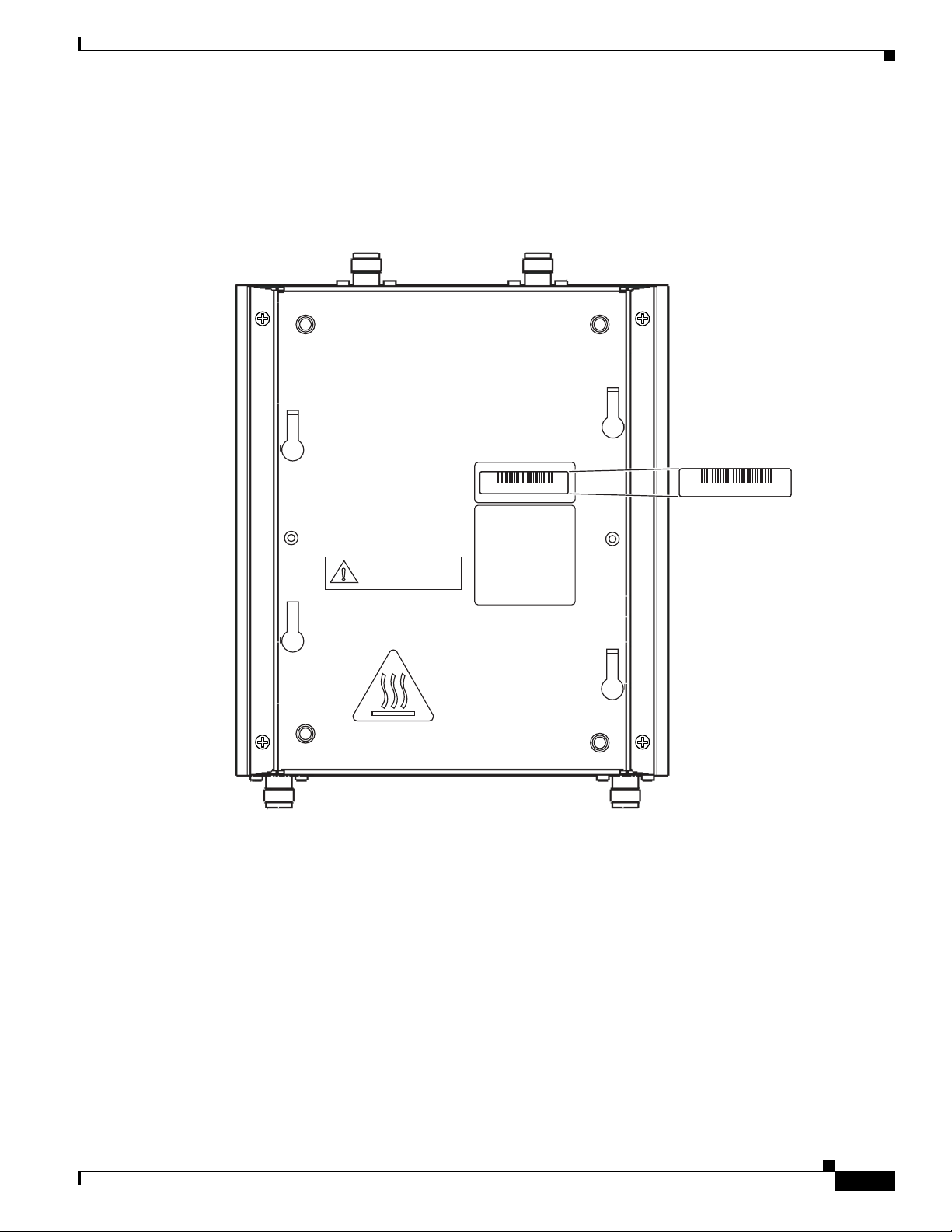
The access point serial number is on the bottom of the housing (refer to Figure 1).
Figure 1 Location of Serial Number Label
Locating the Product Serial Number
OL-8371-05
The access point serial number label contains the following information:
• Model number, such as AIR-AP1242AG-A-k9 or AIR-LAP1242AG-A-k9
• Serial number, such as VDF0636XXXX (11 alphanumeric digits)
• MAC address, such as 00abc65094f3 (12 hexadecimal digits)
• Location of manufacture, such as Made in Singapore
You need your product serial number when requesting support from the Cisco Technical Assistance
Center.
Cisco Aironet 1240AG Series Access Point Hardware Installation Guide
xiii
Page 14

Obtaining Documentation, Obtaining Support, and Security Guidelines
Obtaining Documentation, Obtaining Support, and Security
Guidelines
For information on obtaining documentation, obtaining support, providing documentation feedback,
security guidelines, and also recommended aliases and general Cisco documents, see the monthly
What’s New in Cisco Product Documentation, which also lists all new and revised Cisco technical
documentation, at:
http://www.cisco.com/en/US/docs/general/whatsnew/whatsnew.html
Preface
xiv
Cisco Aironet 1240AG Series Access Point Hardware Installation Guide
OL-8371-05
Page 15

Overview
The Cisco Aironet 1240AG Series Access Point is available in autonomous and lightweight
configurations. The autonomous access points can support standalone network configurations with all
configuration settings maintained within the access points. The lightweight access points operate in
conjunction with a Cisco wireless LAN controller with all configuration information maintained within
the controller.
Product Terminology
The following terms refer to the autonomous and lightweight products:
• The term access point describes both autonomous and lightweight products.
• The term autonomous access point describes only the autonomous product.
• The term lightweight access point describs only the lightweight product.
• The term access point describes a product operating as an access point.
• The term bridge describes a product operating as a bridge.
CHAP T ER
1
Autonomous Access Points
Cisco Aironet 1240AG Series Access Point (AIR-AP1242AG or AIR-AP1242G) provides a secure,
affordable, and easy-to-use wireless LAN solution that combines mobility and flexibility with the
enterprise-class features required by networking professionals. With a management system based on
Cisco IOS software, the 1240AG series is a Wi-Fi certified, wireless LAN transceiver.
The autonomous 1242AG access point contains two integrated radios: a 2.4-GHz radio (IEEE 802.11g)
and a 5-GHz radio (IEEE 801.11a). The autonomous 1242G access point contains a single integrated
radio: a 2.4-GHz radio (IEEE 802.11g).
The access point serves as the connection point between wireless and wired networks or as the center
point of a stand-alone wireless network. In large installations, wireless users within radio range of an
access point can roam throughout a facility while maintaining seamless, uninterrupted access to the
network.
You can configure and monitor the access point using the command-line interface (CLI), the
browser-based management system, or Simple Network Management Protocol (SNMP).
OL-8371-05
Cisco Aironet 1240AG Series Access Point Hardware Installation Guide
1-1
Page 16

Guidelines for Using Cisco Aironet Lightweight Access Points
Lightweight Access Points
The Cisco Aironet 1240AG Series Access Point (AIR-LAP1242AG or AIR-LAP1242G) combines
mobility and flexibility with the enterprise-class features required by networking professionals.These
lightweight access points are part of the Cisco Integrated Wireless Network Solution and require no
manual configuration before they are mounted. The lightweight access point is automatically configured
by a Cisco wireless LAN controller (hereafter called a controller) using the Lightweight Access Point
Protocol (LWAPP).
The lightweight 1242AG access point contains two integrated radios: a 2.4-GHz radio (IEEE 802.11g)
and a 5-GHz radio (IEEE 801.11a). The lightweight 1242G access point contains a single integrated
radio: a 2.4-GHz radio (IEEE 802.11g). Using a controller, you can configure the radio settings.
In the Cisco Centralized Wireless LAN architecture, access points operate in the lightweight mode (as
opposed to autonomous mode). The lightweight access points associate to a controller. The controller
manages the configuration, firmware, and control transactions such as 802.1x authentication. In
addition, all wireless traffic is tunneled through the controller.
LWAPP is an Internet Engineering Task Force (IETF) draft protocol that defines the control messaging
for setup and path authentication and run-time operations. LWAPP also defines the tunneling mechanism
for data traffic.
Chapter 1 Overview
In an LWAPP environment, a lightweight access point discovers a controller by using LWAPP discovery
mechanisms and then sends it an LWAPP join request. The controller sends the lightweight access point
an LWAPP join response allowing the access point to join the controller. When the access point is joined,
the access point downloads its software if the versions on the access point and controller do not match.
After an access point joins a controller, you can reassign it to any controller on your network.
LWAPP secures the control communication between the lightweight access point and controller by
means of a secure key distribution, utilizing X.509 certificates on both the access point and controller.
This chapter provides information on the following topics:
• Guidelines for Using Cisco Aironet Lightweight Access Points, page 1-2
• Hardware Features, page 1-3
• Network Examples with Autonomous Access Points, page 1-8
Guidelines for Using Cisco Aironet Lightweight Access Points
You should keep these guidelines in mind when you use a lightweight access point:
• Lightweight access points can only communicate with Cisco 2006 series wireless LAN controllers
or 4400 series controllers. Cisco 4100 series, Airespace 4012 series, and Airespace 4024 series
controllers are not supported because they lack the memory required to support access points
running Cisco IOS software.
• Lightweight access points do not support Wireless Domain Services (WDS) and cannot
communicate with WDS devices. However, the controller provides functionality equivalent to WDS
when the access point associates to it.
• Lightweight access points support eight BSSIDs per radio and a total of eight wireless LANs per
access point. When a lightweight access point associates to a controller, only wireless LANs with
IDs 1 through 8 are pushed to the access point.
• Lightweight access points do not support Layer 2 LWAPP. They must get an IP address and discover
the controller using DHCP, DNS, or IP subnet broadcast.
1-2
Cisco Aironet 1240AG Series Access Point Hardware Installation Guide
OL-8371-05
Page 17
Chapter 1 Overview
135434
STATUS
RADIO
ETHERNET
MODE
CONSOLE
ETHERNET
48VDC
2.4 GHz RIGHT / PRIMARY
2.4 GHz LEFT
• The lightweight access point console port is enabled for monitoring and debug purposes (all
configuration commands are disabled when the access point is associated to a controller).
Hardware Features
Key hardware features of the access point include:
• Dual-radio operation (see page 1-5)
• Ethernet port (see page 1-5)
• Console port (see page 1-5)
• LEDs, (see page 1-5)
• Multiple power sources (see page 1-6)
• UL 2043 certification (see page 1-6)
• Anti-theft features (see page 1-6)
Refer to Appendix C, “Access Point Specifications,” for a list of access point specifications.
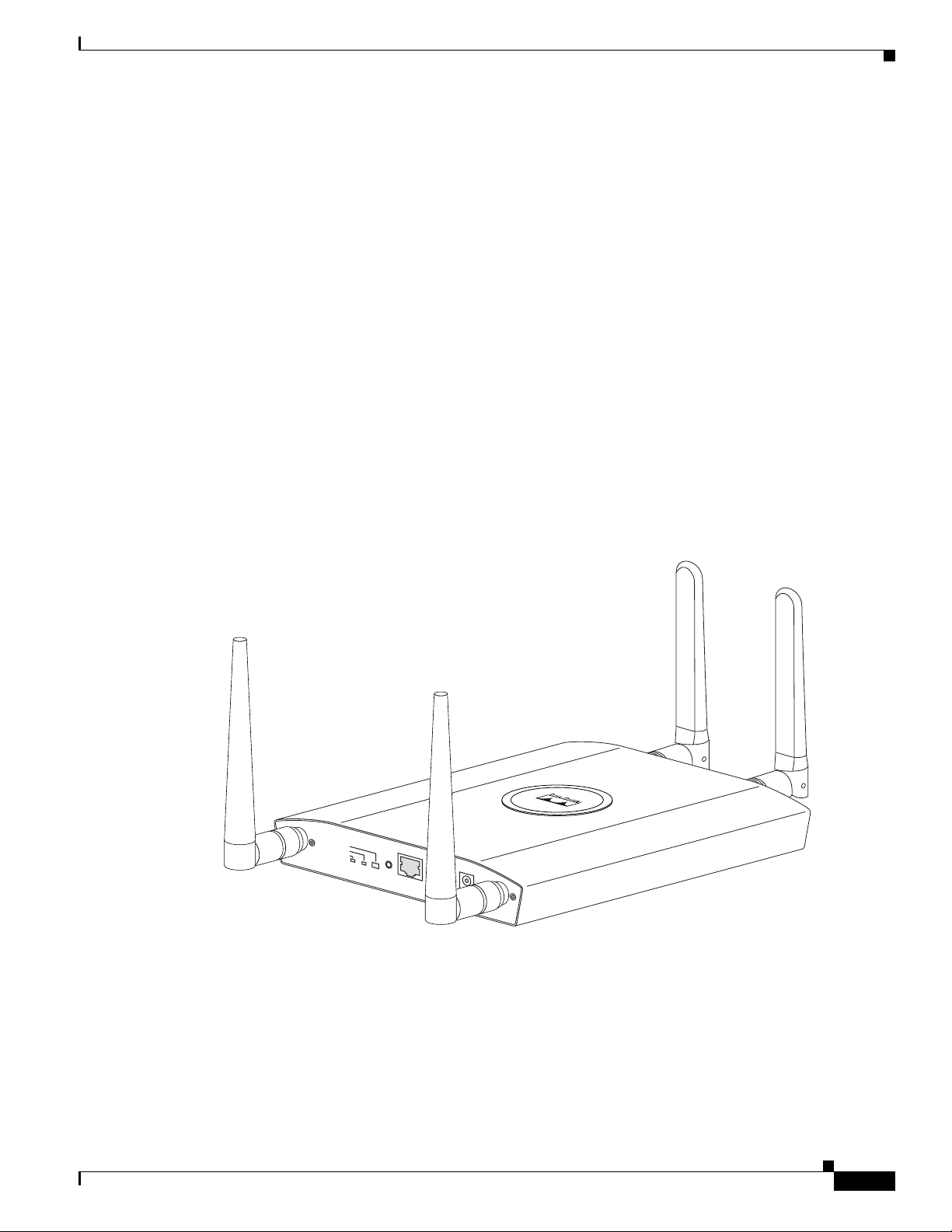
Figure 1-1 shows the access point with antennas.
Hardware Features
Figure 1-1 Access Point with Antennas
OL-8371-05
Cisco Aironet 1240AG Series Access Point Hardware Installation Guide
1-3
Page 18
Hardware Features
STATUS
RADIO
ETHERNET
MODE
CONSOLE
ETHERNET
48VDC
2.4 GHz RIGHT/PRIMARY
2.4 GHz LEFT
135435
6 7 8 91 5432
LEFT
5 GHz ANTENNA w/RP-TNC
135436
1
RIGHT / PRIMARY
23
Chapter 1 Overview
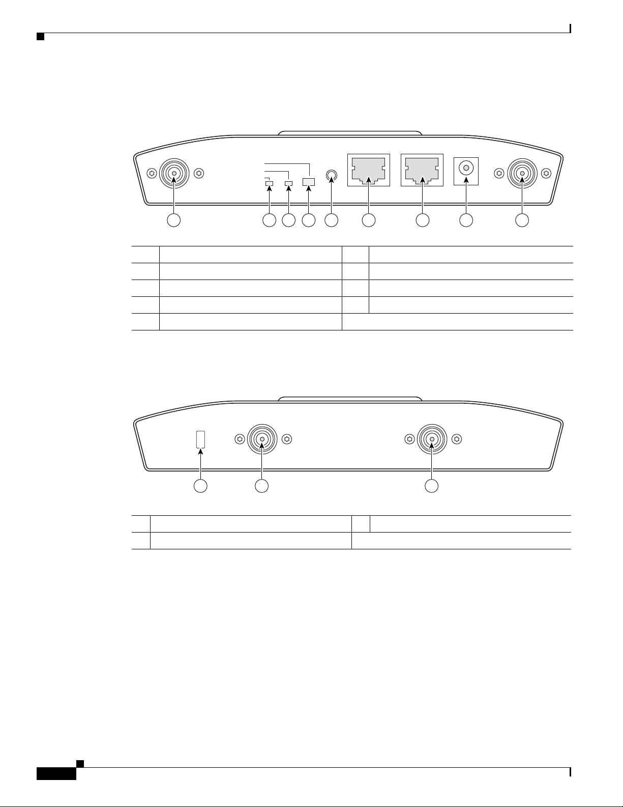
Figure 1-2 illustrates the 2.4-GHz connector end of the access point.
Figure 1-2 Access Point 2.4 GHz Connector End
1 2.4-GHz antenna connector (left) 6 Console port (RJ-45)
2 Ethernet LED 7 Ethernet port (RJ-45)
3 Radio LED 8 48-VDC power port
4 Status LED 9 2.4-GHz antenna connector (right/primary)
5 Mode button
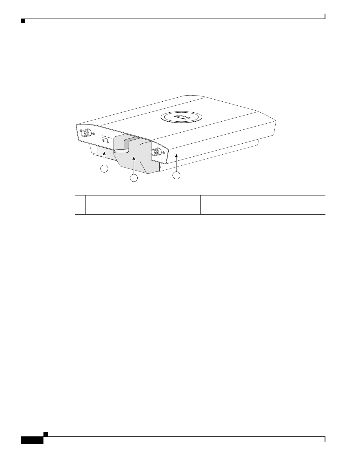
Figure 1-3 illustrates the 5-GHz connector end of the access point.
Figure 1-3 Access Point 5-GHz Connector End
1 5-GHz antenna connector (left) 3 Security key slot
2 5-GHz antenna connector (right/primary)
1-4
Cisco Aironet 1240AG Series Access Point Hardware Installation Guide
OL-8371-05
Page 19

Chapter 1 Overview
Single or Dual-Radio Operation
The 1242AG access point supports simultaneous radio operation using a 2.4-GHz 802.11g radio and a
5-GHz 802.11a radio. The 1242G access point supports a single 2.4-GHz 802.11g radio. Each radio uses
dual-diversity integrated antennas.
The 5-GHz radio incorporates an Unlicensed National Information Infrastructure (UNII) radio
transceiver operating in the UNII 5-GHz frequency bands. The 802.11g radio is called Radio0 and the
802.11a radio is called Radio1.
Antennas Supported
The 1242AG access point supports a wide range of antennas that you can connect to the RP-TNC
connectors on the 2.4-GHz and 5-GHz radios. For a complete list fo supported antennas, refer to the
Cisco Aironet 2.4 GHz and 5 GHz Antennas and Accessories datasheet at this URL:
http://www.cisco.com/en/US/products/hw/wireless/ps469/products_data_sheets_list.html
Ethernet Port
Hardware Features
Console Port
Note After completing your configuration changes, you must remove the serial cable from the access point.
LEDs
The auto-sensing Ethernet port (see Figure 1-2) accepts an RJ-45 connector, linking the access point to
your 10BASE-T or 100BASE-T Ethernet LAN. The access point can receive power through the Ethernet
cable from a power injector, switch, or power patch panel. The Ethernet MAC address is printed on the
label on the back of the access point (refer to the “Locating the Product Serial Number” section on
page xiii).
The serial console port can be used to monitor the access point power-up sequences using a terminal
emulator program. The port is located on the end of the unit (see Figure 1-2). Use an RJ-45 to DB-9 serial
cable to connect your computer’s COM port to the access point’s serial console port. (Refer to
Appendix E, “Console Cable Pinouts,” for a description of the console port pinouts.) Assign the
following port settings to a terminal emulator to open the management system pages: 9600 baud, 8 data
bits, No parity, 1 stop bit, and no flow control.
The access point has three LEDs to indicate Ethernet activity, radio activity, and status indications (refer
to the “Checking the Autonomous Access Point LEDs” section on page 3-2 or the “Checking the
Lightweight Access Point LEDs” section on page 4-3 for additional information). Figure 1-2 shows the
location of the LEDs.
• The Status LED provides general operating status and error indications.
• The Ethernet LED signals Ethernet traffic on the wired Ethernet LAN and provides Ethernet error
indications.
OL-8371-05
• The Radio LED signals that wireless packets are being transmitted or received over the radio
interface and provides radio error indications.
Cisco Aironet 1240AG Series Access Point Hardware Installation Guide
1-5
Page 20

Hardware Features
Power Sources
Chapter 1 Overview
The access point can receive power from an external power module or from inline power using the
Ethernet cable. The access point supports the IEEE 802.3af inline power standard and Cisco CDP Power
Negotiation. Using inline power, you do not need to run a power cord to the access point because power
is supplied over the Ethernet cable.
Warning
Caution Be careful when handling the access point; the bottom plate might be hot.
This product must be connected to a Power over Ethernet (PoE) IEEE 802.3af compliant power source
or an IEC60950 compliant limited power source.
Statement 353
The access point supports the following power sources:
• Power module
• Inline power:
–
Cisco Aironet Power Injector (AIR-PWRINJ3 or AIR-PWRINJ-FIB)
–
An inline power capable switch, such as the Cisco Catalyst 3550 PWR XL, 3560-48PS,
3570-48PS, 4500 with 802.3AF PoE module, or the 6500 with 802.3AF PoE module
–
Other inline power switches supporting the IEEE 802.3af inline power standard
Note Some switches and patch panels might not provide enough power to operate the access point with both
2.4-GHz and 5-GHz radios. At power-up, if the access point is unable to determine that the power source
can supply sufficient power, the access point automatically deactivates both radios to prevent an
over-current condition. The access point also activates a Status LED low power error indication and
creates an error log entry (refer to the “Checking the Autonomous Access Point LEDs” section on
page 3-2 and the “Checking Basic Settings” section on page 3-3).
UL 2043 Certification
The access point has adequate fire resistance and low smoke-producing characteristics suitable for
operation in a building's environmental air space, such as above suspended ceilings, in accordance with
Section 300-22(c) of the NEC, and with Sections 2-128, 12-010(3) and 12-100 of the Canadian
Electrical Code, Part 1, C22.1.
Caution Only the fiber-optic power injector (AIR-PWRINJ-FIB) has been tested to UL 2043 for operation in a
building’s environmental air space; the AIR-PWRINJ3 power injector and the power module are not
tested to UL 2043 and should not be placed in a building’s environmental air space, such as above
suspended ceilings.
Anti-Theft Features
There are three methods of securing the access point:
Cisco Aironet 1240AG Series Access Point Hardware Installation Guide
1-6
OL-8371-05
Page 21
Chapter 1 Overview
135442
2.4 GHz RIGHT / PRIMARY
2.4 GHz LEFT
1
2
Hardware Features
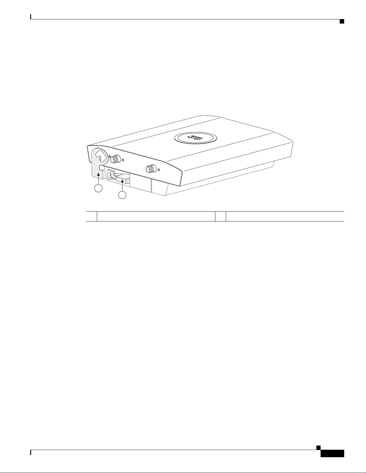
• Security cable keyhole—You can use the security cable slot (see Figure 1-3) to secure the access
point using a standard security cable, like those used on laptop computers (refer to the “Using a
Security Cable” section on page 2-17).
• Security hasp—When you mount the access point on a wall or ceiling using the mounting plate and
the security hasp, you can lock the access point to the plate with a padlock (see Figure 1-4).
Compatible padlocks are Master Lock models 120T and 121T or equivalent.
Figure 1-4 Access Point with Security Hasp and Padlock
1 Security hasp 2 Security padlock
OL-8371-05
Cisco Aironet 1240AG Series Access Point Hardware Installation Guide
1-7
Page 22
Network Examples with Autonomous Access Points
135496
2.4 GHz RIGHT / PRIMARY
2.4 GHz LEFT
STATU S
RADIO
ETHERNET
ETHERNET
48VDC
3
2
1
• Cable security bracket—The cable security bracket (see Figure 1-5) attaches to the mounting plate
and covers the console port, Ethernet port, power port, and the mode button to prevent the
installation or removal of the cables or the activation of the mode button. The cable security bracket
is user removable prior to attaching the mounting plate to a ceiling or wall.
Figure 1-5 Access Point with Mounting Plate and Cable Security Bracket
Chapter 1 Overview
1 Mounting plate 3 Access point
2 Cable security bracket
Network Examples with Autonomous Access Points
This section describes the autonomous access point’s role in three common wireless network
configurations. The autonomous access point’s default configuration is as a root unit connected to a
wired LAN or as the central unit in an all-wireless network.
The autonomous 1240AG series access point supports these operating wireless modes:
• Root access point—Connected to a wired LAN and supports wireless clients.
• Repeater access point—Not connected to a wired LAN, associates to a root access point, and
supports wireless clients
• Workgroup bridge—Not connected to a wired LAN, associates to a root access point or bridge, and
supports wired network devices.
• Root bridge—Connected to a wired LAN and supports non-root bridges and wireless clients.
• Non-root bridge —Not connected to a wired LAN, associates to a root bridge, supports wireless
clients, and supports wired clients.
Cisco Aironet 1240AG Series Access Point Hardware Installation Guide
1-8
OL-8371-05
Page 23
Chapter 1 Overview
Access point
Access point
135445
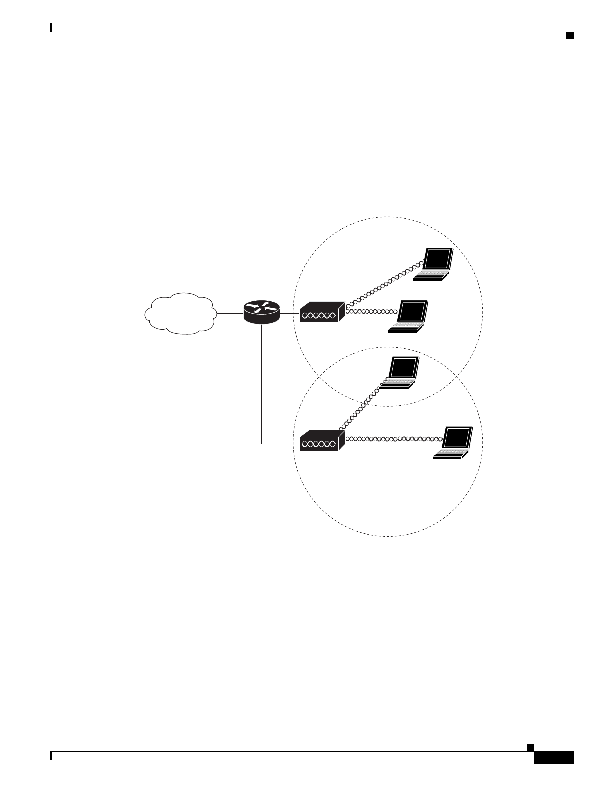
Root Access Point on a Wired LAN
An autonomous access point connected directly to a wired LAN provides a connection point for wireless
users. If more than one autonomous access point is connected to the LAN, users can roam from one area
of a facility to another without losing their connection to the network. As users move out of range of one
access point, they automatically connect to the network (associate) through another access point. The
roaming process is seamless and transparent to the user. Figure 1-6 shows access points acting as root
units on a wired LAN.
Figure 1-6 Access Points as Root Units on a Wired LAN
Network Examples with Autonomous Access Points
OL-8371-05
Cisco Aironet 1240AG Series Access Point Hardware Installation Guide
1-9
Page 24
Network Examples with Autonomous Access Points
Access point Repeater
135444
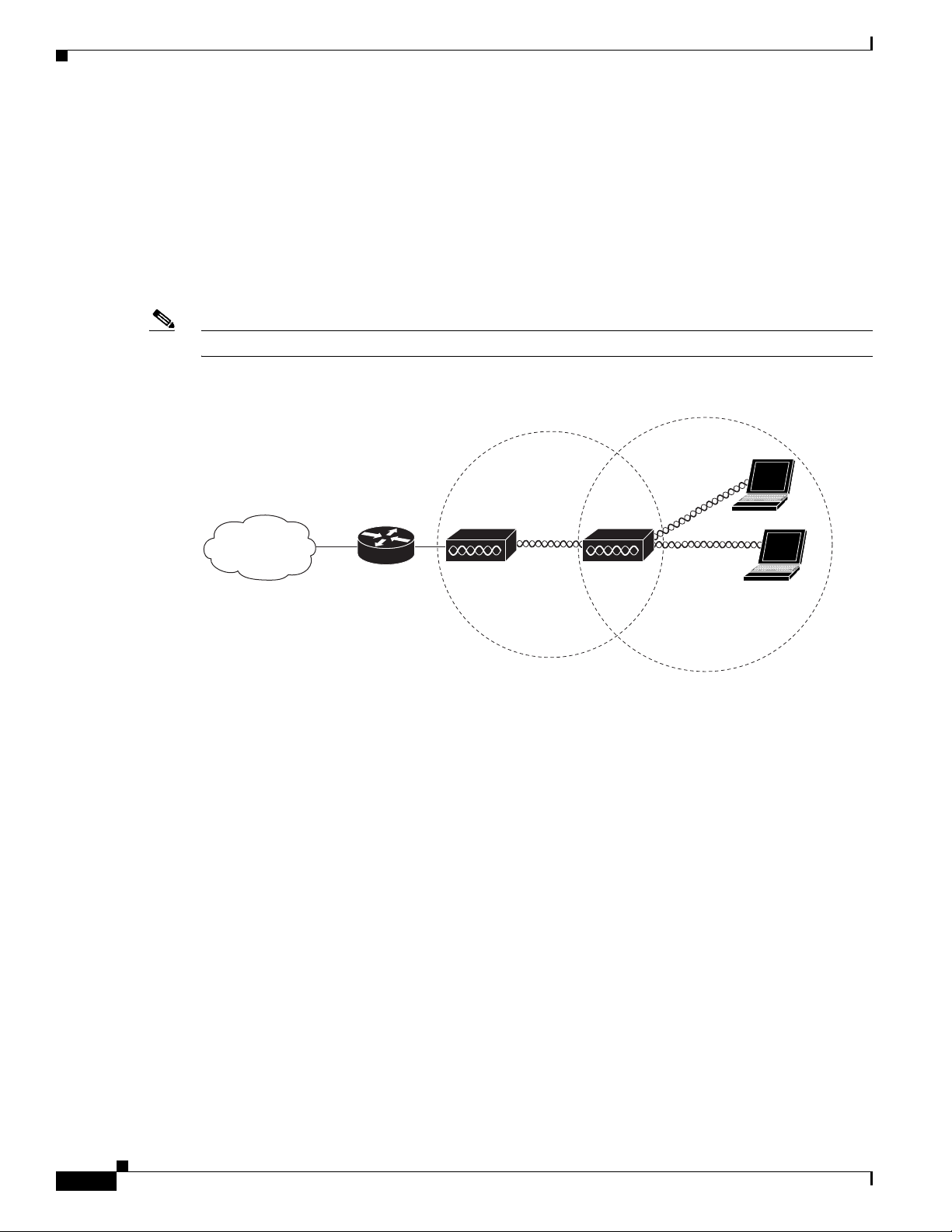
Repeater Unit that Extends Wireless Range
An autonomous access point can be configured as a stand-alone repeater to extend the range of your
infrastructure or to overcome an obstacle that blocks radio communication. The repeater forwards traffic
between wireless users and the wired LAN by sending packets to either another repeater or to an access
point connected to the wired LAN. The data is sent through the route that provides the best performance
for the client. Figure 1-7 shows an autonomous access point acting as a repeater. Consult the Cisco IOS
Software Configuration Guide for Cisco Aironet Access Points for instructions on setting up an access
point as a repeater.
Note Non-Cisco client devices might have difficulty communicating with repeater access points.
Figure 1-7 Access Point as Repeater
Chapter 1 Overview
1-10
Cisco Aironet 1240AG Series Access Point Hardware Installation Guide
OL-8371-05
Page 25
Chapter 1 Overview
Access point
135443
Root bridge Non-root bridge
135446
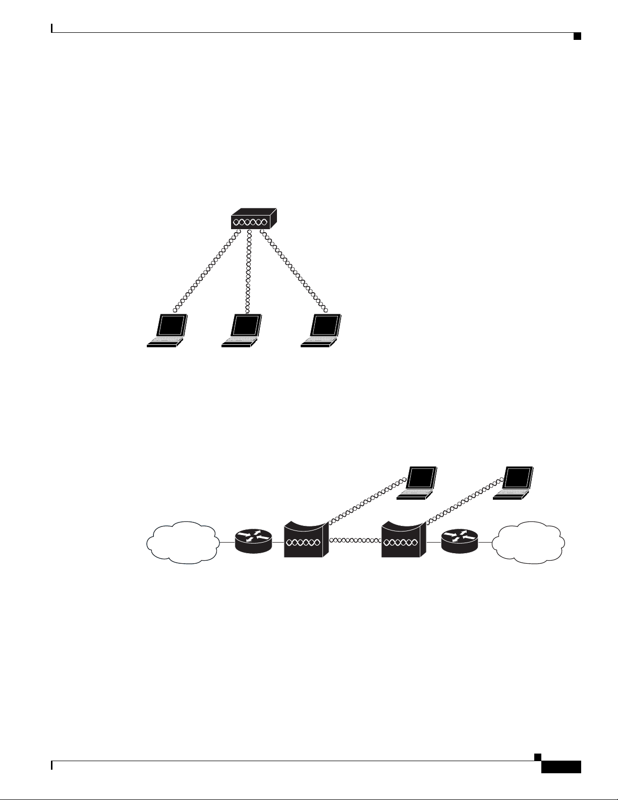
Central Unit in an All-Wireless Network
In an all-wireless network, an autonomous access point acts as a stand-alone root unit. The autonomous
access point is not attached to a wired LAN; it functions as a hub linking all stations together. The access
point serves as the focal point for communications, increasing the communication range of wireless
users. Figure 1-8 shows an autonomous access point in an all-wireless network.
Figure 1-8 Access Point as Central Unit in All-Wireless Network
Network Examples with Autonomous Access Points
Bridge Network with Wireless Clients
The access point supports root bridge and non-root bridge roles used to interconnect a remote LAN to
the main LAN (see Figure 1-9). The bridge units can also support wireless clients.
Figure 1-9 Root Bridge and Non-root Bridge with Clients
OL-8371-05
Cisco Aironet 1240AG Series Access Point Hardware Installation Guide
1-11
Page 26
Network Examples with Autonomous Access Points
117029
Root bridge Non-root bridge
Access point
Workgroup bridge
135448
Bridge Workgroup
bridge
135499
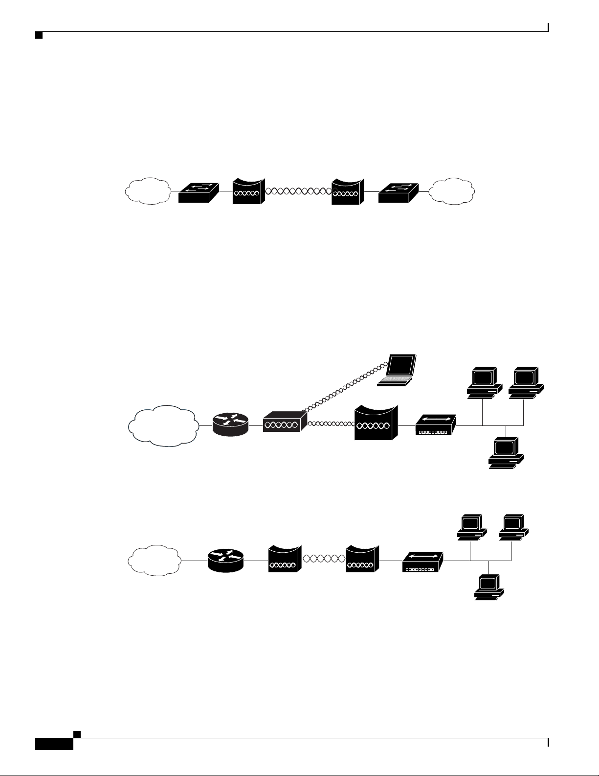
Point-to-Point Bridge Configuration
In a point-to-point bridge configuration, two bridges interconnect two LAN networks using a wireless
communication link (see Figure 1-10). The bridge connected to the main LAN network is classified as
a root bridge and the other bridge is classified as a non-root bridge.
Figure 1-10 Point-to-Point Bridge Configuration
Workgroup Bridge Network
The access point supports a workgroup bridge role to interconnect remote Ethernet workstations to the
main LAN. The workgroup bridge can communicate with an access point (see Figure 1-11) or with a
bridge (see Figure 1-12).
Chapter 1 Overview
Figure 1-11 Workgroup Bridge Communicating with an Access Point
Figure 1-12 Workgroup Bridge Communicating with a Bridge
1-12
Cisco Aironet 1240AG Series Access Point Hardware Installation Guide
OL-8371-05
Page 27
Chapter 1 Overview
158085
LWAPP
LWAPP
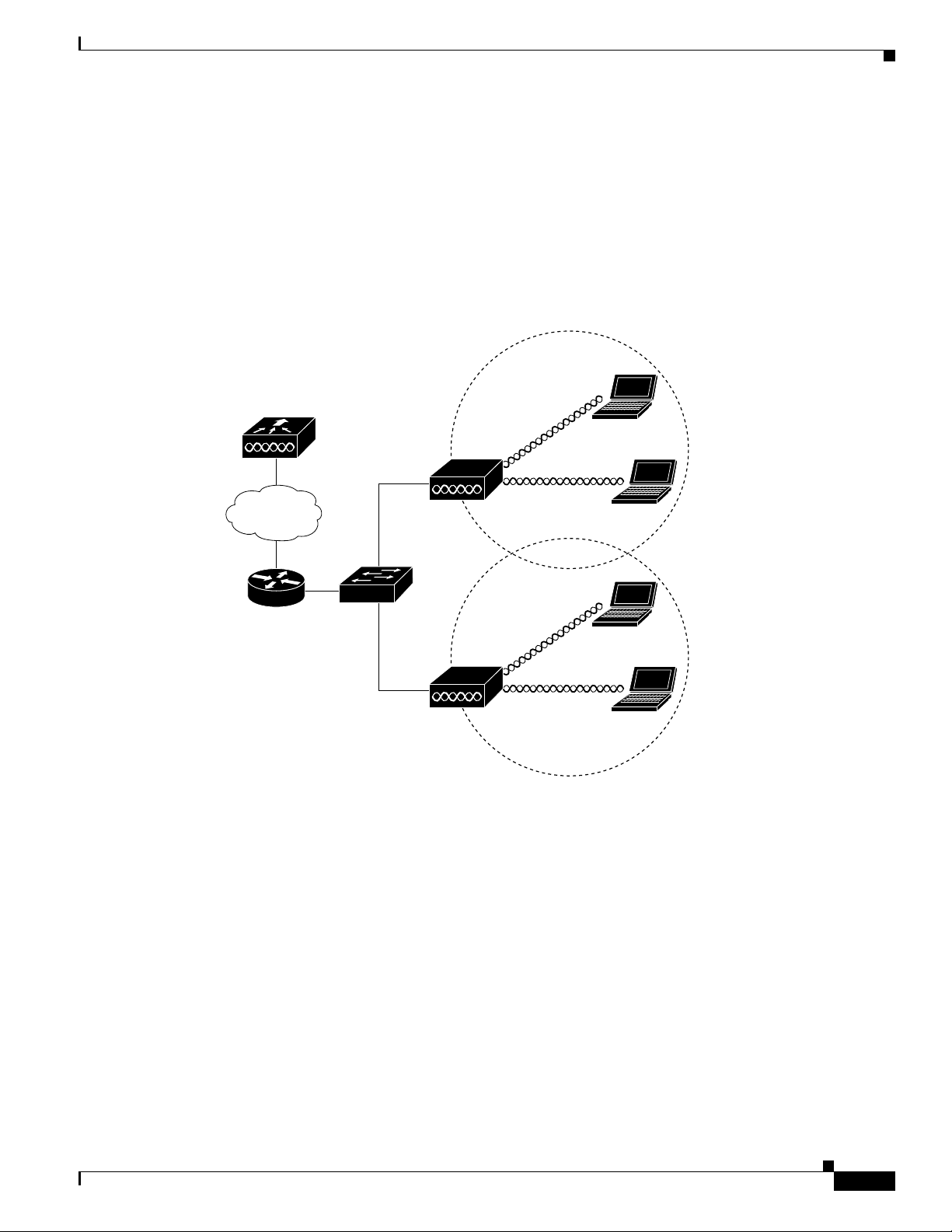
Network Example with Lightweight Access Points
Network Example with Lightweight Access Points
The lightweight access points support Layer 3 network operation. Lightweight access points and
controllers in Layer 3 configurations use IP addresses and UDP packets, which can be routed through
large networks. Layer 3 operation is scalable and recommended by Cisco.
This section illustrates a typical wireless network configuration containing lightweight access points and
a Cisco Wireless LAN Controller (see Figure 1-13).
Figure 1-13 Typical Lightweight Access Point Network Configuration Example
OL-8371-05
Cisco Aironet 1240AG Series Access Point Hardware Installation Guide
1-13
Page 28

Network Example with Lightweight Access Points
Chapter 1 Overview
1-14
Cisco Aironet 1240AG Series Access Point Hardware Installation Guide
OL-8371-05
Page 29

CHAP T ER
2
Installing the Access Point
This chapter describes the installation of the access point and includes these sections:
• Safety Information, page 2-2
• Warnings, page 2-2
• Unpacking the Access Point, page 2-3
• Basic Installation Guidelines, page 2-4
• Controller Discovery Process for Lightweight Access Points, page 2-4
• Mounting Overview, page 2-7
• Mounting on a Horizontal or Vertical Surface, page 2-9
• Mounting Below a Suspended Ceiling, page 2-10
• Mounting Above a Suspended Ceiling, page 2-11
• Mounting Access Point on a Desktop or Shelf, page 2-14
• Cable Security Bracket, page 2-14
• Attaching the Access Point to the Mounting Plate, page 2-16
• Securing the Access Point, page 2-17
• Connecting the Ethernet and Power Cables, page 2-20
• Powering Up the Access Point, page 2-22
OL-8371-05
Cisco Aironet 1240AG Series Access Point Hardware Installation Guide
2-1
Page 30

Safety Information
Safety Information
Follow the guidelines in this section to ensure proper operation and safe use of the access point.
FCC Safety Compliance Statement
The FCC with its action in ET Docket 96-8 has adopted a safety standard for human exposure to radio
frequency (RF) electromagnetic energy emitted by FCC certified equipment. When used with approved
Cisco Aironet antennas, Cisco Aironet products meet the uncontrolled environmental limits found in
OET-65 and ANSI C95.1, 1991. Proper installation of this radio according to the instructions found in
this manual will result in user exposure that is substantially below the FCC recommended limits.
General Safety Guidelines
Do not hold any component containing a radio so that the antenna is very close to or touching any
exposed parts of the body, especially the face or eyes, while transmitting.
Chapter 2 Installing the Access Point
Warnings
Warning
Warning
Warning
Warning
Translated versions of the following safety warnings are provided in Appendix A, “Translated Safety
Warnings.”
This warning symbol means danger. You are in a situation that could cause bodily injury. Before you
work on any equipment, be aware of the hazards involved with electrical circuitry and be familiar
with standard practices for preventing accidents. Use the statement number provided at the end of
each warning to locate its translation in the translated safety warnings that accompanied this device.
Statement 1071
SAVE THESE INSTRUCTIONS
Read the installation instructions before you connect the system to its power source.
This product must be connected to a power-over-ethernet (PoE) IEEE 802.3af compliant power source or an
IEC60950 compliant limited power source.
This product relies on the building’s installation for short-circuit (overcurrent) protection. Ensure that
the protective device is rated not greater than: 20A
Statement 353
Statement 1005
Statement 1004
2-2
Warning
Cisco Aironet 1240AG Series Access Point Hardware Installation Guide
Do not operate your wireless network device near unshielded blasting caps or in an explosive
environment unless the device has been modified to be especially qualified for such use.
Statement 245B
OL-8371-05
Page 31

Chapter 2 Installing the Access Point
Unpacking the Access Point
Warning
In order to comply with FCC radio frequency (RF) exposure limits, antennas should be located at a
minimum of 7.9 inches (20 cm) or more from the body of all persons.
Unpacking the Access Point
Follow these steps to unpack the access point:
Step 1 Open the shipping container and carefully remove the contents.
Step 2 Return all packing materials to the shipping container and save it.
Step 3 Ensure that all items listed in the “Package Contents” section are included in the shipment. Check each
item for damage. If any item is damaged or missing, notify your authorized Cisco sales representative.
Package Contents
Each access point package contains the following items:
• Cisco Aironet 1240AG Series Access Point or Cisco Aironet 1240AG Series Lightweight Access
Point
• Cisco Aironet 1240AG Series Power Module (universal power module)–optional
• Mounting hardware kit
Statement 332
–
One mounting plate with cable security bracket
–
Two suspended ceiling T-rail clips, spacers (accommodates standard and recessed T-rails), and
nuts.
–
One security hasp
–
Two 6 x 32 x 1/2 in. pan head Phillips machine screws
–
Four 8 x 18 x 3/4 in. pan head Phillips sheet metal screws
–
Four #8 plastic wall anchors
–
One 10 x 24 nut (for ground stud on mounting bracket)
–
Four rubber foot pads
–
Two cable tie wraps
• Product quick start guide
• Product translated safety warnings document
• Cisco product registration and Cisco documentation feedback cards
OL-8371-05
Cisco Aironet 1240AG Series Access Point Hardware Installation Guide
2-3
Page 32

Basic Installation Guidelines
Basic Installation Guidelines
Because the access point is a radio device, it is susceptible to interference that can reduce throughput
and range. Follow these basic guidelines to ensure the best possible performance:
• Ensure that a site survey has been performed to determine the optimum placement of access points.
• For lightweight access points, check the latest release notes to ensure that your controller software
version supports the access points to be installed. You can find the controller release notes by
selecting your controller under Wireless LAN Controllers at this URL:
http://www.cisco.com/cisco/web/psa/default.html
• Ensure that access points are not mounted closer than 20 cm (7.9 in) from
• Do not mount the access point within 3 feet of metal obstructions.
• Install the access point away from microwave ovens. Microwave ovens operate on the same
frequency as the access point and can cause signal interference.
• Do not mount the access point outside of buildings.
• Do not mount the access points on building perimeter walls unless outside coverage is desired.
Chapter 2 Installing the Access Point
the body of all persons
.
Controller Discovery Process for Lightweight Access Points
The lightweight access point supports these controller discovery processes:
• DHCP server discovery—Uses DHCP Option 43 to provide controller IP addresses to the access
points. Cisco switches support a DHCP server option. For additional information, refer to the
“Configuring DHCP Option 43 for Lightweight Access Points” section on page G-1.
• DNS server discovery—The access point uses the name CISCO-LWAPP-CONTROLLER.<local
domain> to discover the controller IP addresses from a DNS server. Where <local domain> is the
access point domain name.
• Locally stored controller IP addresses—If the access point was previously associated to a controller,
the IP addresses of the primary, secondary, and tertiary controllers are stored in the access point
non-volatile memory. The process of storing controller IP addresses in access points for later
deployment is called priming the access point. For additional information, refer to the “Priming
Lightweight Access Points Prior to Deployment” section on page F-1.
You can also manually configure controller information using CLI commands on new
(out-of-the-box) access points that are not connected to a controller. For additional information refer
to the “Manually Configuring Controller Information Using the Access Point CLI” section on
page 4-7.
Cisco recommends that you configure a DHCP server with Option 43 to provide the controller IP
addresses to your access points. Cisco switches provide a DHCP server option that is typically used for
this purpose.
2-4
Cisco Aironet 1240AG Series Access Point Hardware Installation Guide
OL-8371-05
Page 33

Chapter 2 Installing the Access Point
Deploying the Access Points on the Wireless Network
Deploying the Access Points on the Wireless Network
Prior to beginning the actual access point deployment, perform these tasks:
• Ensure that a site survey has been preformed.
• Ensure that your network infrastructure devices are operational and properly configured.
• For lightweight access points, perform these tasks:
–
Ensure that your controllers are connected to switch trunk ports.
–
Ensure that your switch is configured with untagged access ports for connecting your access
points.
–
Ensure that a DHCP server with Option 43 configured is reachable by your access points.
To deploy your access points, follow these steps:
Step 1 Obtain the access point location map created during your building site survey.
Step 2 Review the access point locations and identify the specific mounting methods required for each access
point location.
Step 3 For each access point perform these steps:
a. For lightweight access points, record the access point MAC address on the access point location
map. When you have completed the access point deployment, return the access point MAC addresses
and the access point locations on the access point location maps or floor plans to your network
planner or manager. The network operators can use the MAC address and location information to
create maps for precise wireless system management.
b. Attach your access point to the mounting plate (see the “Attaching the Access Point to the Mounting
Plate” section on page 2-16).
c. Mount the access point at the indicated destination using the specified mounting method. For
specific mounting instructions, see these sections:
–
Horizontal or vertical surface, such as a ceiling or wall (see the “Mounting on a Horizontal or
Vertical Surface” section on page 2-9).
–
Below a suspended ceiling (see the “Mounting Below a Suspended Ceiling” section on
page 2-10).
–
Above a suspended ceiling (see the “Mounting Above a Suspended Ceiling” section on
page 2-11).
–
On a desktop or shelf (see the “Mounting Access Point on a Desktop or Shelf” section on
page 2-14.
d. Optionally secure the access point using a padlock or security cable (see the “Securing the Access
Point” section on page 2-17).
e. Connect the access point cables (Ethernet, optional power, optional antennas). For instructions see
the “Connecting the Ethernet and Power Cables” section on page 2-20.
f. On power up, verify that the access point is associated to a controller and operating normally. For
additional information, refer to the “Checking the Autonomous Access Point LEDs” section on
page 3-2 or the “Checking the Lightweight Access Point LEDs” section on page 4-3.
OL-8371-05
Cisco Aironet 1240AG Series Access Point Hardware Installation Guide
2-5
Page 34

Deploying the Access Points on the Wireless Network
STATUS
RADIO
ETHERNET
MODE
CONSOLE
ETHERNET
48VDC
2.4 GHz RIGHT/PRIMARY
2.4 GHz LEFT
135435
6 7 8 91 5432
LEFT
5 GHz ANTENNA w/RP-TNC
135436
1
RIGHT / PRIMARY
23
Step 4 For lightweight access points, after your access points are deployed, ensure that your controller is not
configured as a master controller. A master controller should only be used for configuring access points
and not in a working network.
Access Point Layout and Connectors
Figure 2-1 illustrates the 2.4-GHz connector end of the access point.
Figure 2-1 Access Point 2.4-GHz Connector End
Chapter 2 Installing the Access Point
1 2.4-GHz antenna connector (left) 6 Console port (RJ-45)
2 Ethernet LED 7 Ethernet port (RJ-45)
3 Radio LED 8 48-VDC power port
4 Status LED 9 2.4-GHz antenna connector (right/primary)
5 MODE button
Figure 2-2 illustrates the 5-GHz connector end of the access point.
Figure 2-2 Access Point 5-GHz Connector End
1 5-GHz antenna connector (left) 3 Security key slot )
2 5-GHz antenna connector (right/primary
2-6
Cisco Aironet 1240AG Series Access Point Hardware Installation Guide
OL-8371-05
Page 35

Chapter 2 Installing the Access Point
Mounting Overview
You can mount the access point on any of the following surfaces:
• Horizontal or vertical flat surfaces, such as walls or ceilings
• Suspended ceilings (above and below)
Caution The access point, the antennas, and the power source (power injector or power module) are not designed
for outdoor use and must be located in an indoor environment.
The access point ships with a detachable mounting plate and the necessary mounting hardware. Because
it is detachable, you can use the mounting plate as a template to mark the positions of the mounting holes
for your installation. You then install the mounting plate and attach the access point when you are ready.
Refer to Figure 2-3 to locate the various mounting holes for the method you intend to use.
Figure 2-3 Mounting Plate
Mounting Overview
OL-8371-05
1 Key hole clips 4 Ceiling or wall mounting holes
2 Cable access openings 5 Ground connection
3 Locking detent 6 Cable tie point
Caution Only the fiber-optic power injector (AIR-PWRINJ-FIB) has been tested to UL 2043 for operation in a
building’s environmental air space; no other power injectors or power modules have been tested to UL 2043
and they should not be placed in a building’s environmental air space, such as above suspended ceilings.
Cisco Aironet 1240AG Series Access Point Hardware Installation Guide
2-7
Page 36

Mounting Overview
Note The access point provides adequate fire resistance and low smoke-producing characteristics suitable for
Note When mounting the access point in a building’s environmental air space, you must use Ethernet cable
Chapter 2 Installing the Access Point
operation in a building's environmental air space (such as above suspended ceilings) in accordance with
Section 300-22(C) of the National Electrical Code (NEC).
suitable for operation in environmental air space in accordance with Section 300-22(C) of the National
Electrical Code (NEC).
A mounting hardware kit is provided that contains the hardware and fasteners necessary to mount the
access point. Refer to the Table 2-1 to identify the materials you need to mount your access point, then
go to the section containing the specific mounting procedure.
Table 2-1 Material Needed to Mount Access Point
Mounting Method Materials Required In Kit
Horizontal or vertical surface Four #8 x 1 in. (25.4 mm) screws
Four wall anchors
3/16 in. (4.7 mm) or 3/32 in. (2.3 mm) drill bit
Drill
Standard screwdriver
Suspended ceiling Two T-rail clips with studs
Two plastic spacers
Two 1/4–20 Keps nuts with built-in washers
Standard screwdriver, wrench, or pliers
Yes
Yes
No
No
No
Yes
Yes
Yes
No
2-8
Cisco Aironet 1240AG Series Access Point Hardware Installation Guide
OL-8371-05
Page 37

Chapter 2 Installing the Access Point
Mounting on a Horizontal or Vertical Surface
Mounting on a Horizontal or Vertical Surface
Follow these steps to mount the access point on a horizontal or vertical surface.
Step 1 Use the mounting plate as a template to mark the locations of the four mounting holes.
Note When mounting on a vertical surface, position the cable security bracket on the bottom.
Step 2 Drill one of the following sized holes at the locations you marked:
• 3/16 in. (4.7 mm) if you are using wall anchors
• 1/8 in. (6.3 mm) if you are not using wall anchors
Step 3 Install the anchors into the wall if you are using them. Otherwise, go to Step 4.
Step 4 Secure the mounting plate to the surface using the #8 fasteners.
Note On a vertical surface, mount the plate with the security hasp slot on the top.
Step 5 Attach the access point to the mounting plate.
Note For a more secure installation you should attach the mounting plate to a stud or major structural
member and use the appropriate fasteners.
OL-8371-05
Cisco Aironet 1240AG Series Access Point Hardware Installation Guide
2-9
Page 38

Mounting Below a Suspended Ceiling
Mounting Below a Suspended Ceiling
Note To comply with NEC code, a #10-24 grounding lug is provided on the mounting plate.
You should review Figure 2-4 before beginning the mounting process.
Figure 2-4 T-Rail Mounting Parts
Chapter 2 Installing the Access Point
2-10
1 Suspended ceiling T-rail 4 mounting plate
2 T-rail clips 5 Keps nut (contains an attached lock washer)
Plastic spacer (used with recessed ceiling
3
tiles)
Cisco Aironet 1240AG Series Access Point Hardware Installation Guide
OL-8371-05
Page 39

Chapter 2 Installing the Access Point
Follow these steps to mount your access point on a suspended ceiling:
Step 1 Decide where you want to mount the access point.
Step 2 Attach two T-rail clips to the suspended ceiling T-rail.
Step 3 Use the mounting plate to adjust the distance between the T-rail clips so that they align with the holes in
the mounting plate.
Step 4 Use a standard screwdriver to tighten the T-rail clip studs in place on the suspended ceiling T-rail. Do
not overtighten.
Step 5 If using recessed ceiling tiles, install a plastic spacer on each T-rail clip stud. The spacer’s legs should
contact the suspended ceiling T-rail.
Step 6 Attach the mounting plate to the T-rail clip studs and start a Keps nut on each stud.
Step 7 Use a wrench or pliers to tighten the Keps nuts. Do not overtighten.
Step 8 To attach the access point to the mounting plate, see the “Attaching the Access Point to the Mounting
Plate” section on page 2-16.
Step 9 If you need additional security, refer to the “Securing the Access Point” section on page 2-17 for
additional information.
Step 10 Verify the access point is operating (see the “Powering Up the Access Point” section on page 2-22).
Mounting Above a Suspended Ceiling
Mounting Above a Suspended Ceiling
The access point mounting plate is designed to be integrated into the T-bar grid above the tiles of a
suspended ceiling. Using a T-bar box hanger and bracket mounting clip (not supplied) such as the
Erico 512A and BHC, you orient the access point antenna just above the top surface of a standard ceiling
tile. You may need to modify a thicker tile to allow room for the antenna.
OL-8371-05
Cisco Aironet 1240AG Series Access Point Hardware Installation Guide
2-11
Page 40

Mounting Above a Suspended Ceiling
S
TA
TUS
RADIO
ETHE
RNET
MO
D
E
C
O
N
SO
LE
ET
HER
NE
T
48VDC
2.4 GH
z R
IGH
T / PRIM
AR
Y
2
.4 G
Hz LEFT
4
5
3
3
1
2
2
1
It may be helpful to refer to Figure 2-5 before proceeding.
Figure 2-5 Above Suspended Ceiling Parts
Chapter 2 Installing the Access Point
1
Suspended ceiling T-rail
2
T-rail clip
3
Height adjustment screw
4
T-bar box hanger
5
Bracket mounting clip
Caution Only the fiber-optic power injector (AIR-PWRINJ-FIB) has been tested to UL 2043 for operation in a
building’s environmental air space; no other power injectors or power modules have been tested to UL 2043
and they should not be placed in a building’s environmental air space, such as above suspended ceilings.
Cisco Aironet 1240AG Series Access Point Hardware Installation Guide
2-12
OL-8371-05
Page 41

Chapter 2 Installing the Access Point
135498
The bracket mounting clip requires the use of two mounting clip holes on the mounting plate (see
Figure 2-6).
Figure 2-6 Mounting Plate Holes
Mounting Above a Suspended Ceiling
1 Bracket mounting clip holes
Follow these steps to mount the access point above a suspended ceiling.
Step 1 Insert the bracket mounting clip’s tab into the large hole on the access point mounting plate.
Step 2 Place the clip over the T-bar box hanger and secure it to the access point mounting plate (see Figure 2-7)
with the 1/4-20 fastener (supplied with the T-bar hanger).
Figure 2-7 Access Point Mounting Plate
OL-8371-05
Note The illustration shows the access point mounting plate mounted perpendicular to the T-bar box
hanger. You can also mount the bracket parallel to the T-bar box hanger.
Cisco Aironet 1240AG Series Access Point Hardware Installation Guide
2-13
Page 42

Mounting Access Point on a Desktop or Shelf
Step 3 Determine the location in the ceiling where you will mount the access point and remove an adjacent
ceiling tile.
Step 4 Orient the access point 2-GHz and 5-GHz antennas so that they are pointing down when mounted on the
T-bar Box hanger.
Step 5 Adjust the height of the T-bar box hanger to provide antenna clearance above the ceiling tile using the
height adjusting screws (refer to Figure 2-5).
Step 6 Attach the T-rail clips on each end of the T-bar box hanger to the ceiling grid T-rails. Make sure the clips
are securely attached to the T-rails.
Step 7 Connect a drop wire to a building structural element and through the hole provided in the bracket
mounting clip. This additional support is required in order to comply with the U.S. National Electrical
Safety Code.
Step 8 To attach the access point to the mounting plate, see the “Attaching the Access Point to the Mounting
Plate” section on page 2-16.
Step 9 If you need additional security, see the “Securing the Access Point” section on page 2-17 for additional
information.
Step 10 Verify the access point is operating before replacing the ceiling tile (see the “Powering Up the Access
Point” section on page 2-22).
Chapter 2 Installing the Access Point
Mounting Access Point on a Desktop or Shelf
When placing the access point on a desktop of shelf, the use of the mounting plate is optional. The
mounting plate can be used to shield the user from the hot bottom surface of the access point when
movement of the access point may be necessary. The access point is shipped with four rubber pads that
you can place on the bottom of the access point or the mounting plate to help prevent sliding or
scratching the surface of your desktop or shelf. For information on connecting the access point cables,
see the “Connecting the Ethernet and Power Cables” section on page 2-20.
Cable Security Bracket
The access point mounting plate has an attached cable security bracket that covers the console port,
Ethernet port, power port, and the mode button to prevent the installation or removal of the cables or the
activation of the mode button. If desired, the cable security bracket can be removed prior to attaching the
mounting plate to a ceiling or wall.
2-14
Cisco Aironet 1240AG Series Access Point Hardware Installation Guide
OL-8371-05
Page 43

Chapter 2 Installing the Access Point
135496
2.4 GHz RIGHT / PRIMARY
2.4 GHz LEFT
STATU S
RADIO
ETHERNET
ETHER
NET
48VDC
3
2
1
Figure 2-8 Access Point with Mounting Plate and Cable Security Bracket
1 Mounting plate 3 Access point
2 Cable security bracket
Cable Security Bracket
Removing the Cable Security Bracket
The cable security bracket (see Figure 2-9) is designed to help prevent someone from using the Mode
button to reset the access point to default values or from using the serial console cable to access the
access point’s CLI interface or from removing the Ethernet cable. If this security protection is not
considered necessary, you can remove the cable security bracket.
Figure 2-9 Cable Security Bracket Screws
1 Cable security bracket 3 Mounting plate
2 Cable security bracket screws
OL-8371-05
Cisco Aironet 1240AG Series Access Point Hardware Installation Guide
2-15
Page 44

Chapter 2 Installing the Access Point
Attaching the Access Point to the Mounting Plate
To remove the cable security bracket from the mounting plate, follow these instructions:
Step 1 Position the mounting plate with the cable security bracket pointing down (see Figure 2-9).
Step 2 Remove the two screws that attach the bracket to the mounting plate using a phillips screw driver.
Attaching the Access Point to the Mounting Plate
Follow these steps to attach the access point to the mounting plate:
Step 1 If your mounting plate has the cable security bracket, follow these steps:
a. Connect the Ethernet cable to the access point Ethernet port (see the “Connecting the Ethernet and
Power Cables” section on page 2-20).
b. If not using on-line power, connect the power module’s power cable to the access point 48-VDC
connector.
c. Carefully feed the Ethernet and power cables through the cable notch on the cable security bracket
and slide the cables to the right or left to secure the cables (see the “Cable Security Bracket” section
on page 2-14).
Note If your access point is connected to Ethernet in-line power, do not connect the local power
module to the access point. Using two power sources on the access point might cause the access
point to shut down to protect internal components and might cause the switch to shut down the
port to which the access point is connected. If your access point shuts down, you must remove
all power and reconnect only a single power source.
Step 2 Line up the four keyhole clips on the mounting plate with the large ends of the keyhole-shaped holes on
the access point.
Note The keyhole clips on each side of the mounting plate are offset and can only be positioned in one
direction onto the access point.
Step 3 Insert the mounting plate clips into the keyhole shaped holes on the access point.
Step 4 Slide the access point towards the cable security bracket end of the mounting bracket while exerting
slight pressure to force the access point and mounting plate together. You will hear a slight click when
the locking detents contact the access point and locks it into place.
Step 5 Attach and adjust the antenna(s) or antenna cables to the access point antenna connectors.
Note The 5-GHz antennas and antenna cables have a blue dot or blue label. Connect only antennas or
antenna cables with blue dots or labels to the access point’s 5-GHz antenna connectors.
2-16
Cisco Aironet 1240AG Series Access Point Hardware Installation Guide
OL-8371-05
Page 45

Chapter 2 Installing the Access Point
Step 6 If your mounting plate does not have the cable security bracket, follow these steps:
a. Connect a CAT 5 Ethernet cable to the access point Ethernet port (see the “Connecting the Ethernet
and Power Cables” section on page 2-20).
b. If using local power, insert the power module’s power cable into the access point’s 48-VDC power
port.
Note If your access point is connected to in-line power, do not connect the power module to the access
point. Using two power sources on the access point might cause the access point to shut down
to protect internal components and might cause the switch to shut down the port to which the
access point is connected. If your access point shuts down, you must remove all power and
reconnect only a single power source.
Securing the Access Point
Securing the Access Point
There are two ways to secure your access point:
• Using a security cable
• Securing the access point to the mounting plate
Using a Security Cable
You can secure the access point by installing a standard security cable (such as the Kensington Notebook
MicroSaver, model number 64068) into the access point security cable slot (see Figure 2-2). The security
cable can be used with any of the mounting methods described in this guide.
Follow these steps to install the security cable.
Step 1 Loop the security cable around a nearby immovable object.
Step 2 Insert the key into the security cable lock.
Step 3 Insert the security cable latch into the security key slot on the access point.
Step 4 Rotate the key right or left to secure the security cable lock to the access point.
Step 5 Remove the key from security cable lock.
OL-8371-05
Cisco Aironet 1240AG Series Access Point Hardware Installation Guide
2-17
Page 46

Securing the Access Point
135491
2.4 GHz RIGHT / PRIMARY
2.4 GHz LEFT
2
3
1
4
6
5
Securing the Access Point to the Mounting Plate
The security hasp enables you to use a padlock to secure the access point to the mounting plate. Known
compatible padlocks are Master Lock models 120T or 121T.
To install the security hasp, follow these steps:
Step 1 Insert the security hasp’s key pin (see Figure 2-10) into the key slot on the access point (see Figure 2-2)
and rotate counterclockwise towards the mounting plate.
Figure 2-10 Security Hasp
Chapter 2 Installing the Access Point
Step 2
1 Key pin 4 Padlock
2 Security hasp 5 5-GHz access point end
3 Mounting plate security slot 6 Mounting plate
Push the security hasp’s padlock flange through the mounting plate’s security slot.
2-18
Cisco Aironet 1240AG Series Access Point Hardware Installation Guide
OL-8371-05
Page 47

Chapter 2 Installing the Access Point
135442
2.4 GHz RIGHT / PRIMARY
2.4 GHz LEFT
1
2
Step 3 Place your padlock (user supplied) through the padlock hole in the security hasp’s padlock flange
(see Figure 2-11).
Figure 2-11 Security Hasp and Padlock
1 Security hasp 2 Pad lock
Securing the Access Point
Step 4
Push the padlock into the recessed opening between the access point and the mounting plate.
Note When attaching the mounting plate to a vertical surface, place the security cable bracket end of the
mounting plate on the bottom.
OL-8371-05
Cisco Aironet 1240AG Series Access Point Hardware Installation Guide
2-19
Page 48

Connecting the Ethernet and Power Cables
Power
cord
Universal
power supply
S
Y
S
T
R
P
S
D
U
P
L
X
M
O
D
E
S
P
E
E
D
U
T
I
L
S
T
A
T
1
2
3
4
5
6
7
8
9
1
0
1
1
12
1
3
1
4
15
16
1
7
1
8
1
9
20
21
22
2
3
2
4
23
2
4
1
0
B
a
s
e
T
/
1
0
0
B
a
s
e
T
X
1
0
0
B
a
s
e
F
X
C
a
ta
ly
s
t 2
9
5
0
S
E
R
I
E
S
S
Y
S
T
R
P
S
D
U
P
L
X
M
O
D
E
S
P
E
E
D
U
T
IL
S
T
A
T
1
2
3
4
5
6
7
8
9
1
0
11
12
1
3
14
1
5
1
6
1
7
18
1
9
20
21
2
2
23
2
4
2
3
24
1
0
B
a
s
e
T
/
1
0
0
B
a
s
e
T
X
1
0
0
B
a
s
e
F
X
C
a
ta
ly
s
t 2
9
5
0
S
E
R
I
E
S
T
O
A
P
/
B
R
I
D
G
E
TO
N
E
T
W
O
R
K
Switch with
inline power
Power injector
Access Point
Switch without
inline power
Option 1 Option 2
Option 3
135476
Connecting the Ethernet and Power Cables
The access point receives power through the Ethernet cable or an external power module. Figure 2-12
shows the power options for the access point.
Figure 2-12 Access Point Power Options
Chapter 2 Installing the Access Point
Warning
This product must be connected to a Power over Ethernet (PoE) IEEE 802.3af compliant power source
or an IEC60950 compliant limited power source.
Statement 353
Caution This product and all interconnected equipment must be installed indoors within the same building,
including the associated LAN connections (as defined by Environment A of the IEEE 802.3af standard).
Cisco Aironet 1240AG Series Access Point Hardware Installation Guide
2-20
The access point power options:
• Option 1—Switches with sufficient inline power:
–
An inline power capable switch, such as the Cisco Catalyst 3550 PWR XL, 3560-48PS,
3750-48PS, 4500 with 802.3AF PoE module, or the 6500 with 802.3AF PoE module
–
Other inline power switches supporting the IEEE 802.3af inline power standard
• Option 2—Switches without sufficient inline power can use the power injector:
–
Cisco Aironet Power Injector (AIR-PWRINJ3 or AIR-PWRINJ-FIB)
• Option 3—Local power using the power module
OL-8371-05
Page 49

Chapter 2 Installing the Access Point
STATUS
RADIO
ETHERNET
MODE
CONSOLE
ETHERNET
48VDC
2.4 GHz RIGHT/PRIMARY
2.4 GHz LEFT
135494
1 2
Connecting the Ethernet and Power Cables
Note Some older switches and patch panels might not provide enough power to operate the access point. At
power-up, if the access point is unable to determine that the power source can supply sufficient power,
the access point automatically deactivates both radios to prevent an over-current condition. The access
point Status LED turns amber and an error log entry is created (refer to the “Checking the Autonomous
Access Point LEDs” section on page 3-2 or the “Checking the Lightweight Access Point LEDs” section
on page 4-3).
Connecting to an Ethernet Network with an Inline Power Source
Caution Be careful when handling the access point; the bottom plate might be hot.
Note If your access point is connected to in-line power, do not connect the power module to the access point.
Using two power sources on the access point might cause the access point to shut down to protect internal
components and might cause the switch to shut down the port to which the access point is connected. If
your access point shuts down, you must remove all power and reconnect only a single power source.
Follow these steps to connect the access point to the Ethernet LAN when you have an inline power
source:
Step 1 Connect a Category 5 Ethernet cable to the RJ-45 Ethernet connector labeled Ethernet on the access
point (see Figure 2-13).
Figure 2-13 Ethernet and Power Ports
1 Ethernet port 2 48 VDC power port
Step 2
Connect the other end of the Ethernet cable to one of the following:
• A switch with inline power (see the “Connecting the Ethernet and Power Cables” section on
page 2-20).
• The end of a Cisco Aironet power injector labeled To AP/Bridge. Connect the other end labeled To
Network to your 10/100 Ethernet LAN.
OL-8371-05
Cisco Aironet 1240AG Series Access Point Hardware Installation Guide
2-21
Page 50

Powering Up the Access Point
Connecting to an Ethernet Network with Local Power
Caution Be careful when handling the access point; the bottom plate might be hot.
Note If your access point is connected to in-line power, do not connect the power module to the access point.
Using two power sources on the access point might cause the access point to shut down to protect internal
components and might cause the switch to shut down the port to which the access point is connected. If
your access point shuts down, you must remove all power and reconnect only a single power source.
Follow these steps to connect the access point to an Ethernet LAN when you are using a local power
source:
Step 1 Connect a Category 5 Ethernet cable to the RJ-45 Ethernet connector labeled Ethernet on the access
point (see Figure 2-13).
Step 2 Connect the power module output connector to the access point’s 48-VDC power port (see Figure 2-13).
Chapter 2 Installing the Access Point
Step 3 Plug the other end of the Ethernet cable into an unpowered Ethernet port on your LAN network.
Step 4 Plug the other end of the power module into an approved 100- to 240-VAC outlet.
For information on securing your access point, see the “Securing the Access Point” section on page 2-17.
Powering Up the Access Point
When power is applied to the access point, it begins a routine power-up sequence that you can monitor
by observing the three LEDs on the end of the access point. After you observe all three LEDs turning
green to indicate the starting of the operating system, the Status LED blinks green signifying that the
access point is operational. After a successful power-up sequence, the Status LED turns light green to
signify that there are no client devices associated, or it turns blue to signify that there are client devices
associated. Refer to the “Checking the Autonomous Access Point LEDs” section on page 3-2 or the
“Checking the Lightweight Access Point LEDs” section on page 4-3 for LED descriptions.
Caution Be careful when handling the access point; the bottom plate might be hot.
Note If your access point is connected to in-line power, do not connect the power module to the access point.
Using two power sources on the access point might cause the access point to shut down to protect internal
components and might cause the switch to shut down the port to which the access point is connected. If
your access point shuts down, you must remove all power and reconnect only a single power source.
2-22
Cisco Aironet 1240AG Series Access Point Hardware Installation Guide
OL-8371-05
Page 51

CHAP T ER
3
Troubleshooting 1240AG Series Autonomous Access Points
This chapter provides troubleshooting procedures for basic problems with the 1240AG series
autonomous access point (AIR-AP1242AG or AIR-AP1242G). For the most up-to-date, detailed
troubleshooting information, refer to the Cisco Technical Support and Documentation website at the
following URL:
http://www.cisco.com/cisco/web/psa/default.html
Sections in this chapter include:
• Checking the Autonomous Access Point LEDs, page 3-2
• Checking Basic Settings, page 3-3
• Low Power Condition, page 3-5
• Running the Carrier Busy Test, page 3-13
• Running the Ping Test, page 3-14
• Resetting to the Default Configuration, page 3-14
• Reloading the Access Point Image, page 3-16
• Obtaining the Access Point Image File, page 3-19
• Obtaining the TFTP Server Software, page 3-20
OL-8371-05
Cisco Aironet 1240AG Series Access Point Hardware Installation Guide
3-1
Page 52

Chapter 3 Troubleshooting 1240AG Series Autonomous Access Points
STATUS
RADIO
ETHERNET
MODE
CONSOLE
ETHERNET
48VDC
2.4 GHz RIGHT/PRIMARY
2.4 GHz LEFT
135497
321
Checking the Autonomous Access Point LEDs
Checking the Autonomous Access Point LEDs
If your access point is not working properly, check the Status, Ethernet, and Radio LEDs on the 2.4 GHz
end of the unit. You can use the LED indications to quickly assess the unit’s status. Figure 3-1 shows the
access point LEDs (for additional information refer to the Event Log using the access point browser
interface).
Figure 3-1 Access Point LEDs
1 Ethernet LED 3 Status LED
2 Radio LED
The LED signals are listed inTable 3-1.
Table 3-1 LED Signals
Message type Ethernet LED Radio LED Status LED Meaning
Boot loader status Green Green Green DRAM memory test ok.
Off Blinking green Blue-green Initialize Flash file system.
Off Green Pink Flash memory test ok.
Green Off Dark blue Ethernet test ok.
Green Green Green Starting Cisco IOS.
Association status — — Light green Normal operating condition, but no wireless client
devices are associated with the unit.
— — Blue Normal operating condition, at least one wireless
client device is associated with the unit.
Operating status Green — — Ethernet link is operational.
Blinking green — — Transmitting or receiving Ethernet packets.
— Blinking green — Transmitting or receiving radio packets.
——Blinking
Software upgrade in progress
dark blue
3-2
Cisco Aironet 1240AG Series Access Point Hardware Installation Guide
OL-8371-05
Page 53

Chapter 3 Troubleshooting 1240AG Series Autonomous Access Points
Table 3-1 LED Signals (continued)
Message type Ethernet LED Radio LED Status LED Meaning
Boot loader warnings Off Off Yellow Ethernet link not operational.
Red Off Yellow Ethernet failure.
Amber Off Yellow Configuration recovery in progress
(Mode button pressed for 2 to 3 seconds).
Off Red Pink Image recovery
(Mode button pressed for 20 to 30 seconds)
Blinking green Blinking red Blinking
pink
Boot loader errors Red Red Red DRAM memory test failure.
Off Red Blinking red
and blue
Off Amber Blinking red
and
blue-green
Amber Off Blinking red
and yellow
Red Off Blinking red
and off
Amber Amber Blinking red
and off
Red Amber Blinking red
and off
Amber Amber Blinking red
and off
Cisco IOS errors Blinking
amber
— Blinking amber — Maximum retries or buffer full occurred on the
Red Red Amber Software failure; try disconnecting and
— — Amber General warning, insufficient inline power (see the
— — Transmit or receive Ethernet errors.
Image recovery in progress and Mode button is
released.
Flash file system failure.
Environment variable (ENVAR) failure.
Bad MAC address.
Ethernet failure during image recovery.
Boot environment error.
No Cisco IOS image file.
Boot failure.
radio.
reconnecting unit power.
Low Power Condition section).
Checking Basic Settings
Checking Basic Settings
Mismatched basic settings are the most common causes of lost connectivity with wireless clients. If the
access point does not communicate with client devices, check the following areas.
OL-8371-05
Cisco Aironet 1240AG Series Access Point Hardware Installation Guide
3-3
Page 54

Checking Basic Settings
Default IP Address Behavior
When you connect a 1240 series access point running Cisco IOS Release 12.3(7)JA or later software with
a default configuration to your LAN, the access point requests an IP address from your DHCP server
and, if it does not receive an IP address, continues to send requests indefinitely.
Enabling the Radio Interfaces
In Cisco IOS Release 12.3(7)JA or later, the access point radios are disabled by default, and there is no
default SSID. You must create an SSID and enable the radios before the access point will allow wireless
associations from other devices. These changes to the default configuration improve the security of
newly installed access points. Refer to the Cisco IOS Software Configuration Guide for Cisco Aironet
Access Points for instructions on configuring the SSID.
To enable the radio interfaces, follow these instructions:
Step 1 Use your web-browser to access your access point.
Step 2 At the prompts, enter the administrator username and password. The default username is Cisco and the
default password is Cisco. The username and password are case sensitive.
Step 3 When the Summary Status page displays, click Network Interfaces > Radio0-802.11G and the radio
status page displays.
Chapter 3 Troubleshooting 1240AG Series Autonomous Access Points
SSID
Step 4 Click Settings and the radio settings page displays.
Step 5 Click Enable in the Enable Radio field.
Step 6 Click Apply.
Step 7 Click Radio1-802.11A and the radio status page displays.
Step 8 Repeat Steps 3 to 5.
Step 9 Close your web-browser.
Wireless clients attempting to associate with the access point must use the same SSID as the access point.
If a client device’s SSID does not match the SSID of an access point in radio range, the client device will
not associate.
Note In Cisco IOS Release 12.3(7)JA or later, there is no default SSID. You must configure an SSID before
client devices can associate to the access point.
3-4
Cisco Aironet 1240AG Series Access Point Hardware Installation Guide
OL-8371-05
Page 55

Chapter 3 Troubleshooting 1240AG Series Autonomous Access Points
WEP Keys
The WEP key you use to transmit data must be set up exactly the same on your access point and any
wireless devices with which it associates. For example, if you set WEP Key 3 on your client adapter to
0987654321 and select it as the transmit key, you must also set WEP Key 3 on the access point to exactly
the same value. The access point does not need to use Key 3 as its transmit key, however.
Refer to the Cisco IOS Software Configuration Guide for Cisco Aironet Access Points for instructions
on setting the access point’s WEP keys.
Security Settings
Wireless clients attempting to authenticate with your access point must support the same security options
configured in the access point, such as EAP or LEAP, MAC address authentication, Message Integrity
Check (MIC), WEP key hashing, and 802.1X protocol versions.
If a wireless client is unable to authenticate with your access point, contact the system administrator for
proper security settings in the client adapter and for the client adapter driver and firmware versions that
are compatible with the access point settings.
Low Power Condition
Note The access point MAC address that displays on the Status page in the Aironet Client Utility (ACU) is
the MAC address for the access point radio. The MAC address for the access point Ethernet port is
printed on the label on the back of the access point.
Low Power Condition
Warning
This product must be connected to a Power over Ethernet (PoE) IEEE 802.3af compliant power source
or an IEC60950 compliant limited power source.
The access point can be powered from the 48-VDC power module or from an in-line power source. The
access point supports the IEEE 802.3af power standard, Cisco Pre-Standard PoE protocol, and Cisco
Intelligent Power Management for in-line power sources.
For full operation, the access point (powered device) requires 12.95 W (up to 15.4 W with 100 m
CAT 5 Ethernet cable). When the access point is being used in a PoE configuration, the power drawn
from the power sourcing equipment (PSE), such as a switch or power injector, is higher by an amount
dependent on the length of the interconnecting cable.
The power module and Cisco Aironet power injectors are capable of supplying the required power for
full operation, but some inline power sources are not capable of supplying sufficient power. Also, some
high-power inline power sources, might not be able to provide up to 15.4 W of power to all ports at the
same time.
Statement 353
OL-8371-05
Note An 802.3af compliant switch (Cisco or non-Cisco) is capable of supplying sufficient power for full
operation.
Cisco Aironet 1240AG Series Access Point Hardware Installation Guide
3-5
Page 56

Low Power Condition
Note If your access point is connected to in-line power, do not connect the power module to the access point.
Using two power sources on the access point might cause the access point to shut down to protect internal
components and might cause the switch to shut down the port to which the access point is connected. If
your access point shuts down, you must remove all power and reconnect only a single power source.
On power up, the access point is placed into low power mode (both radios are disabled), Cisco IOS
software loads and runs, and power negotiation determines if sufficient power is available. If there is
sufficient power then the radios are turned on; otherwise, the access point remains in low power mode
with the radios disabled to prevent a possible over-current condition. In low power mode, the access
point activates the Status LED low power error indication, displays a low power message on the browser
and serial interfaces, and creates an event log entry (see the “Checking the Autonomous Access Point
LEDs” section on page 3-2 and “Inline Power Status Messages” section on page 3-7).
Intelligent Power Management
The access point requires 12.95 W of power (up to 15.4 W with 100 m CAT 5 Ethernet cable) for full
power operation with both radios, but only needs 6.3 W of power when operating in low power mode
with both radios disabled. To help avoid an over-current condition with low power sources and to
optimize power usage on Cisco switches, Cisco developed Intelligent Power Management, which uses
Cisco Discovery Protocol (CDP) to allow powered devices (such as your access point) to negotiate with
a Cisco switch for sufficient power.
Chapter 3 Troubleshooting 1240AG Series Autonomous Access Points
The access point supports Intelligent Power Management and as a result of the power negotiations, the
access point will either enter full power mode or remain in low power mode with the radios disabled.
Note Independent of the power negotiations, the access point hardware also uses the 802.3af classification
scheme to indicate the power required from the power source. However, the power source cannot report
the power available to the access point unless the power source also supports Intelligent Power
Management.
Some Cisco switches that are capable of supplying sufficient power require a software upgrade to
support Intelligent Power Management. If the software upgrade is not desired, you can configure the
access point to operate in pre-standard compatibility mode and the access point automatically enters full
power mode if these Cisco switches are detected in the received CDP ID field.
When the access point determines that sufficient power is not available for full power operation, an error
message is logged and the Status LED turns amber to indicate low power mode (see the “Checking the
Autonomous Access Point LEDs” section on page 3-2 and the “Inline Power Status Messages” section
on page 3-7).
Tip If your switch is capable of supplying sufficient power for full operation but the access point remains in
low-power mode, your access point or your switch (or both) might be misconfigured (see Tabl e 3-2 and
Table 3- 3).
3-6
Cisco Aironet 1240AG Series Access Point Hardware Installation Guide
OL-8371-05
Page 57

Chapter 3 Troubleshooting 1240AG Series Autonomous Access Points
If your inline power source is not able to supply sufficient power for full operation, you should consider
these options:
• Upgrade to a higher-powered switch
• Use a Cisco Aironet power injector on the switch port
• Use the 48-VDC power module to locally power the access point
Inline Power Status Messages
These messages are logged on the console port by the access point to report the power condition:
• %CDP_PD-4-POWER_OK: Full Power - AC_ADAPTOR inline power source—This message
indicates the access point is using the power module and can support full-power operation.
• %CDP_PD-4-POWER_OK: Full Power - NEGOTIATED inline power source—This message
indicates the access point is operating at full power and has successfully negotiated for 12.95 W of
power from a Cisco switch supporting Cisco Intelligent Power Management.
• %CDP_PD-4-POWER_OK: Full Power - HIGH_POWER_CLASSIC inline power source—This
message indicates the access point is operating at full power because it has been configured for
pre-standard compatibility mode and has detected a Cisco switch that does not support Intelligent
Power Management but is able to supply sufficient power to the access point.
Low Power Condition
• %CDP_PD-4-POWER_OK: Full Power - INJECTOR_CONFIGURED_ON_SOURCE inline power
source—This message indicates the access point is operating at full power because it is connected
to a Cisco switch that supports Intelligent Power Management and the switch has been configured
with the power inline never command.
• %CDP_PD-4-POWER_OK: Full power - INJECTOR_CONFIGURED_ON_CURRENT_PORT
inline power source—This message indicates the access point is operating at full power because it
has been configured to expect a power injector on this port.
• %CDP_PD-4-POWER_OK: Full Power - INJECTOR_DETECTED_PD inline power source—This
message indicates the access point is operating at full power because it has detected a CDP packet
from another Cisco powerable device (PD). The access point power is being supplied from a power
injector or a non-Cisco power source because a Cisco power source does not transmit this type of
CDP packet.
• %CDP_PD-4-POWER_OK: Full Power - INJECTOR_DETECTED_MULTIPLE_MACS_ON_
HUB inline power source—This message indicates the access point is operating at full power
because it has detected multiple Cisco devices. The access point power is being supplied from a
power injector or a non-Cisco power source because a Cisco power source does not forward CDP
packets.
• %CDP_PD-4-POWER_OK: Full Power - NON_CISCO-NO_CDP_RECEIVED inline power
source—This message indicates the access point is operating at full power because it has not
received any CDP packets within the timeout period. This condition indicates your access point is
connected to a non-Cisco power source.
OL-8371-05
Note To prevent possible over-current conditions, the power source must be an
compliant power source or an IEC60950 compliant limited power source.
Cisco Aironet 1240AG Series Access Point Hardware Installation Guide
IEEE 802.3af
3-7
Page 58

Low Power Condition
Chapter 3 Troubleshooting 1240AG Series Autonomous Access Points
• %CDP_PD-2-POWER_LOW: All radios disabled - NEGOTIATED inline power source—This
message indicates the access point is in low power mode with all radios disabled because the Cisco
power source has indicated it is not capable of supplying sufficient power to the access point.
Note A Cisco power injector might be required.
• %CDP_PD-2-POWER_LOW: All radios disabled - LOW_POWER_CLASSIC_NO_INJECTOR
_CONFIGURED <platform name> (<MAC address>). —This message indicates the access point is
in low power mode with all radios disabled and has detected a CDP device that is unable to supply
sufficient power to the access point.
The< platform name> indicates the CDP device detected by the access point. The <MAC address>
indicates the MAC address of the CDP device, typically, the switch port.
Note A Cisco power injector might be required.
Following the low power status message, two extra messages are displayed on the console port or
when using a Telnet session that identify the actions needed to resolve this low power problem:
–
Verify the required power injector is installed on this port: <platform name> (<Ethernet port>).
(where <platform name> indicates the CDP device detected by the access point and
<Ethernet port> indicates the Ethernet port of the CDP device.
–
If a power injector is installed, issue the command: power inline negotiation injector installed.
• %CDP_PD-2-POWER_LOW: All radios disabled- LOW_POWER_CLASSIC_INJECTOR_
CONFIGURED_ON_ANOTHER_PORT <platform name> (<MAC address>)—This message
indicates the access point is in low power mode with all radios disabled and has detected a CDP
device that is unable to supply sufficient power to the access point. A power injector has been
configured, but it is for another port. It is likely that the access point has been relocated and has not
been reconfigured for a new power injector.
The <platorm name> indicates the CDP device detected by the access point. The <MAC address>
indicates the MAC address of the CDP device, typically, the switch port.
Note A Cisco power injector might be required.
Following the low power status message, two extra messages are displayed when using the console
port or a Telnet session that identify the actions needed to resolve this low power problem:
1. Verify the required power injector is installed on the new port: <platform name> (<Ethernet
port>).
(where <platform name> indicates the CDP device detected by the access point and
<Ethernet port> indicates the Ethernet port of the CDP device.
2. If a power injector is installed, issue the command: power inline negotiation injector installed.
• %CDP_PD-2-POWER_LOW: All radios disabled- HIGH_POWER_CLASSIC_NOT_
CONFIGURED inline power source <platform name> (<MAC address>)—This message indicates
the access point is in low power mode with all radios disabled and has detected a Cisco switch that
does not support Intelligent Power Management, but should be able to supply sufficient power. The
access point must be configured for pre-standard compatibility.
3-8
Cisco Aironet 1240AG Series Access Point Hardware Installation Guide
OL-8371-05
Page 59

Chapter 3 Troubleshooting 1240AG Series Autonomous Access Points
The< platform name> indicates the Cisco platform detected by the access point. The <MAC
address> indicates the MAC address of the switch port.
Note You need to upgrade the software on the Cisco switch to support Intelligent Power
Management or configure the access point for pre-standard compatibility.
• %CDP_PD-4-POWER_OK: Full power - INJECTOR_CONFIGURED_OVERRIDE_SAFETY
inline power source —This message indicates the access point has been configured to override the
inline power checks and a power injector is installed.
Caution When using the power inline negotiation injector override command, a power injector must always be
installed to prevent a possible overload condition with an underpowered power source.
Configuring Power Using the CLI
Intelligent Power Management support is dependent on the version of software resident in the Cisco
switch that is providing power to the access point. Each Cisco switch should be upgraded to support
Intelligent Power Management. Until the software is upgraded, you can configure the access point to
operate with older switch software using the following Cisco IOS CLI command:
[no] power inline negotiation {prestandard source |injector {installed | override |
H.H.H}}
Low Power Condition
(prestandard source indicates the Cisco switch does not support Intelligent Power
Management. injector installed indicates a power injector is installed on the current
switch port. injector override indicates a power injector is installed and the access
point is configured to override the inline power checks. When you move the access point,
H.H.H is used to specify the MAC address of the new switch port where the access point was
moved. A MAC address of 0.0.0 is invalid.)
Caution When using the power inline negotiation injector override command, a power injector must always be
installed to prevent a possible overload condition with an underpowered power source.
Note The power inline negotiation injector installed command will fail if CDP is disabled.
When using the power inline negotiation injector override command, you must use a power injector to
prevent possibly overloading underpowered power sources.
You can use this Cisco IOS CLI command to inform the access point of the following:
• The Cisco switch does not support Intelligent Power Management but should be able to supply
sufficient power.
• A power injector is being used to supply sufficient power and the Cisco switch does not support
Intelligent Power Management.
• The access point was moved to a new Cisco switch port and a power injector is being used to supply
sufficient power.
OL-8371-05
Cisco Aironet 1240AG Series Access Point Hardware Installation Guide
3-9
Page 60

Chapter 3 Troubleshooting 1240AG Series Autonomous Access Points
Low Power Condition
Caution If the access point receives power through PoE, the output current of the power sourcing equipment
(PSE) cannot exceed 400 mA per port. The power source must comply with IEEE802.3af or IEC60950
for limited power sources.
Note After completing your configuration changes, you must remove the serial console cable from the access
point.
Table 3-2 Using Cisco IOS Commands
Cisco IOS Commands
Power Source
AC power module None required power inline never
Cisco switch that supports Intelligent Power
Management
Cisco switch that does not support Intelligent
Power Management
Power injector
supports Intelligent Power Management
1
1
2
used with a Cisco switch that
1
Power injector2 used with a Cisco switch that
does not support Intelligent Power
Management
1
Power injector used with a non-Cisco switch None required –
802.3af compliant non-Cisco switches None required –
1. You should check the release notes for your Cisco power source to determine which Cisco IOS release supports Intelligent Power Management. Support
for Intelligent Power Management might not be currently available for your Cisco power source.
2. Power injector must be AIR-PWRINJ3 or AIR-PWRINJ-FIB.
3. The Cisco switch uses Intelligent Power Management to inform the access point of the power injector being used.
4. Cisco switches that support Intelligent Power Management always configure the use of a power injector at the switch.
Access Point Cisco Switch
no power inline negotiation prestandard source
power inline auto
no power inline negotiation injector
power inline negotiation prestandard source
power inline auto
no power inline negotiation injector
None required
no power inline negotiation prestandard source
3
power inline never
power inline never
power inline negotiation injector installed
4
Issuing the Cisco IOS Command Using the CLI
Follow these steps to issue the Cisco IOS command for your power scenario:
Step 1 Connect a PC to the access point console port and use a terminal emulator to establish a session with the
access point (refer to the “Connecting to the Access Point Locally” section on page 3-20).
Step 2 From the global configuration mode (refer to the Cisco IOS Software Configuration Guide for Cisco
Aironet Access Points), enter the command below that applies to your power configuration (see
Table 3- 2):
• power inline negotiation injector installed
• no power inline negotiation injector
• power inline negotiation prestandard source
• no power inline negotiation prestandard source
Cisco Aironet 1240AG Series Access Point Hardware Installation Guide
3-10
OL-8371-05
Page 61

Chapter 3 Troubleshooting 1240AG Series Autonomous Access Points
Low Power Condition
Step 3 Enter the write memory command to save the setting to the access point memory.
Step 4 Enter the quit command to exit the terminal session.
Configuring the Access Point System Power Settings Using a Browser
You can also use your browser to set the access point System Power Settings.
Note The access point web-browser interface is fully compatible with Microsoft Internet Explorer version 6.0
on Windows 98 and 2000 platforms and with Netscape version 7.0 on Windows 98, Windows 2000, and
Solaris platforms.
Note When using the access point browser interface, you should disable your browser pop-up blocker.
Figure 3-2 shows the system power setting options and indicates the power status of the access point.
Figure 3-2 System Power Settings
Caution If the access point receives power through PoE, the output current of the power sourcing equipment
(PSE) cannot exceed 400 mA per port. The power source must comply with IEEE802.3af or IEC60950
for limited power sources.
Table 3- 3 lists the access point system power settings and the Cisco switch power commands for several
power options.
Table 3-3 Access Point System Power Settings and Cisco Switch Commands
Cisco Switch
Power Source Access Point System Power Settings
Power Command
AC power module Configuration changes are not required power inline never
Cisco switch that supports
Intelligent Power Management
Power Settings:
1
Power Negotiation (selected)
power inline auto
Power Injector:
OL-8371-05
Installed on Port with MAC Address (unchecked)
Cisco Aironet 1240AG Series Access Point Hardware Installation Guide
3-11
Page 62

Chapter 3 Troubleshooting 1240AG Series Autonomous Access Points
Low Power Condition
Table 3-3 Access Point System Power Settings and Cisco Switch Commands (continued)
Cisco Switch
Power Source Access Point System Power Settings
Cisco switch that does not
support Intelligent Power
Management
1
Power Settings:
Pre-standard Compatibility (selected)
Power Injector:
Installed on Port with MAC Address (unchecked)
Power injector
Cisco switch that supports
Intelligent Power Management
2
used with a
Power Settings:
1
Power Negotiation (selected)
Power Injector:
Installed on Port with MAC Address (unchecked)
Power injector2 used with a
Cisco switch that does not
support Intelligent Power
Management
1
Power Settings:
Power Negotiation (selected)
Power Injector:
Installed on Port with MAC Address (checked)
Power injector used with a
Configuration changes are not required –
non-Cisco switch
802.3af compliant non-Cisco
Configuration changes are not required –
switches
1. You should check the release notes for your Cisco power source to determine which Cisco IOS release supports Intelligent Power Management. Support
for Intelligent Power Management might not be currently available for your Cisco power source.
2. Power injector must be AIR-PWRINJ3 or AIR-PWRINJ-FIB.
3. Cisco switches that support Intelligent Power Management always configure the use of a power injector at the switch.
Power Command
power inline auto
power inline never
power inline never
3
3-12
Perform these steps to configure your access point power settings using the browser interface:
Step 1 Obtain the access point IP address and browse to your access point.
Step 2 At the prompt, enter the administrator username and password. The default username is Cisco and the
default password is Cisco. The username and password are case sensitive.
Step 3 Perform one of these operations:
a. When you browse to your access point operating in low-power mode, a Warning message displays
indicating that all radios are disabled due to insufficient power. Click OK to jump to the System
Power Settings located on the System Software > System Configuration page.
b. When you browse to your access point operating in full-power mode, choose System Software >
System Configuration.
Step 4 Choose one of these Power Settings options (see Figure 3-2):
a. If your Cisco switch supports Intelligent Power Management negotiations, choose Power
Negotiation.
b. If your Cisco switch does not support Intelligent Power Management negotiations, choose
Pre-standard Compatibility.
c. If you are using a non-Cisco switch, changes to the power settings are not required.
Cisco Aironet 1240AG Series Access Point Hardware Installation Guide
OL-8371-05
Page 63

Chapter 3 Troubleshooting 1240AG Series Autonomous Access Points
Step 5 If you are using a power injector with a Cisco switch, choose one of these Power setting options (see
Figure 3-2):
a. If your Cisco switch supports Intelligent Power Management negotiations, uncheck Installed on
Port with MAC address.
b. If your Cisco switch does not support Intelligent Power Management, check Installed on Port with
MAC address and ensure the MAC address for your switch port is displayed in the MAC address
field. The HHHH.HHHH.HHHH indicates the MAC address contains 12 hexadecimal digits.
Note The MAC address field is not case-sensitive.
Step 6 Click Apply and a message displays indicating that you should disable pop-up blockers before
proceeding.
Step 7 Click OK to continue. Your access point reboots and your power settings are configured in the access
point.
Note You might have to refresh your browser page to obtain the latest browser page that indicates your
radios are enabled.
Running the Carrier Busy Test
Running the Carrier Busy Test
You can use the carrier busy test to determine the least conjested channel for a radio interface (802.11g
or 802.11a). You should typically run the test several times over several days to obtain the best results
and to avoid temporary activity spikes.
Note The carrier busy test is primarily used for single access points or bridge environments. For sites with
multiple access points, a site survey is typically performed to determine the best operation location and
operating frequency for the access points.
Note All associated clients on the selected radio will be deassociated during the 6 to 8 seconds needed for the
carrier busy test.
Perform these steps to activate the carrier busy test:
Step 1 Use your web browser to access the access point browser interface.
Step 2 At the prompt, enter the administrator username and password. The default username is Cisco and the
default password is Cisco. The username and password are case sensitive.
Step 3 Click Network Interfaces and the Network Interface Summary page displays.
Step 4 Choose the radio interface experiencing problems by clicking Radio0-802.11G or Radio1-802.11A.
The respective radio status page displays.
Step 5 Click the Carrier Busy Test tab and the Carrier Busy Test page displays
OL-8371-05
Cisco Aironet 1240AG Series Access Point Hardware Installation Guide
3-13
Page 64

Running the Ping Test
Step 6 Click Start to begin the carrier busy test.
When the test completes, the results are displayed on the page. For each of the channel center
frequencies, the test produces a value indicating the percentage of time that the channel is busy.
Running the Ping Test
You can use the ping test to evaluate the link to and from an associated wireless device. The ping test
provides two modes of operation:
a. Performs a test using a specified number of packets and then displays the test results.
b. Performs a test that continuously operates until you stop the test and then displays the test results.
Follow these steps to activate the ping test:
Step 1 Use your web browser to access the access point browser interface.
Step 2 At the prompt, enter the administrator username and password. The default username is Cisco and the
default password is Cisco. The username and password are case sensitive.
Chapter 3 Troubleshooting 1240AG Series Autonomous Access Points
Step 3 Click Association and the main association page displays.
Step 4 Click the MAC address of an associated wireless device and the Statistics page for that device displays.
Step 5 Click the Ping/Link Test tab and the Ping/Link Test page displays.
Step 6 If you want to specify the number of packets to use in the test, follow these steps:
a. Enter the number of packets in the Number of Packets field
b. Enter the packet size in the Packet Size field.
c. Click Start.
Step 7 If you want to use a continuous test, follow these steps:
a. Enter the packet size in the Packet Size field.
b. Click Start to activate the test.
c. Click Stop to stop the test.
When the test has completed, the test results are displayed at the bottom of the page. You should check
for any lost packets that can indicate a problem with the wireless link. For best results, you should also
perform this test several times.
Resetting to the Default Configuration
3-14
If you forget the password that allows you to configure the access point, you may need to completely
reset the configuration. You can use the MODE button on the access point or the web-browser interface.
Note The following steps reset all configuration settings to factory defaults, including passwords, WEP keys,
the IP address, and the SSID.
Cisco Aironet 1240AG Series Access Point Hardware Installation Guide
OL-8371-05
Page 65

Chapter 3 Troubleshooting 1240AG Series Autonomous Access Points
Using the MODE Button
Follow these steps to delete the current configuration and return all access point settings to the factory
defaults using the MODE button:
Step 1 Disconnect power (the power jack for external power or the Ethernet cable for in-line power) from the
access point.
Step 2 Press and hold the MODE button while you reconnect power to the access point.
Step 3 Hold the MODE button until the Ethernet LED turns an amber color (approximately 2 to 3 seconds), and
release the button.
Step 4 After the access point reboots, you must reconfigure the access point by using the Web browser interface,
the Telnet interface, or Cisco IOS commands.
Note The access point is configured with the factory default values including the IP address (set to
receive an IP address using DHCP).
Resetting to the Default Configuration
Using the Web Browser Interface
Follow these steps to delete the current configuration and return all access point settings to the factory
defaults using the web browser interface.
Step 1 Open your Internet browser.
Note The access point web-browser interface is fully compatible with Microsoft Internet Explorer
version 6.0 on Windows 98 and 2000 platforms and with Netscape version 7.0 on Windows 98,
Windows 2000, and Solaris platforms.
Note When using the access point browser interface, you should disable your browser pop-up blocker.
Step 2 Enter the access point’s IP address in the browser address line and press Enter. An Enter Network
Password page displays.
Step 3 At the prompt, enter the administrator username and password. The default username is Cisco and the
default password is Cisco. The username and password are case sensitive. The Summary Status page
displays.
Step 4 Click System Software and the System Software page displays.
Step 5 Click System Configuration and the System Configuration page displays.
OL-8371-05
Cisco Aironet 1240AG Series Access Point Hardware Installation Guide
3-15
Page 66

Reloading the Access Point Image
Step 6 Click the Reset to Defaults button.
Note If the access point is configured with a static IP address, the IP address does not change.
Step 7 After the access point reboots, you must reconfigure the access point by using the Web browser interface,
the Telnet interface, or Cisco IOS commands.
Reloading the Access Point Image
If your access point has a firmware failure, you must reload the complete access point image file using
the Web browser interface or by using the MODE button. You can use the browser interface if the access
point firmware is still fully operational and you want to upgrade the firmware image. However, you can
use the MODE button when the access point has a corrupt firmware image.
Chapter 3 Troubleshooting 1240AG Series Autonomous Access Points
Using the MODE Button
You can use the MODE button on the access point to reload the access point image file from an active
Trivial File Transfer Protocol (TFTP) server on your network or on a PC connected to the access point
Ethernet port.
Note If your access point experiences a firmware failure or a corrupt firmware image, indicated by the Status
LED turning an amber color, you must reload the image from a connected TFTP server.
Note This process resets all configuration settings to factory defaults, including passwords, WEP keys, the
access point IP address, and SSIDs.
Follow these steps to reload the access point image file:
Step 1 The PC you intend to use must be configured with a static IP address in the same subnet as the access
point.
Step 2 Place a copy of the access point image file (such as c1240-k9w7-tar.123-8.JA.tar) into the TFTP server
folder on your PC. For additional information, refer to the “Obtaining the Access Point Image File” and
“Obtaining the TFTP Server Software” sections.
Step 3 Rename the access point image file in the TFTP server folder to c1240-k9w7-tar.default.
Step 4 Activate the TFTP server.
3-16
Step 5 If using in-line power, use a Category 5 (CAT5) Ethernet cable to connect your PC to the To N e t wor k
Ethernet connector on the power injector.
Step 6 Disconnect power (the power jack for external power or the Ethernet cable for in-line power) from the
access point.
Step 7 Press and hold the MODE button while you reconnect power to the access point.
Cisco Aironet 1240AG Series Access Point Hardware Installation Guide
OL-8371-05
Page 67

Chapter 3 Troubleshooting 1240AG Series Autonomous Access Points
Step 8 Hold the MODE button until the Radio LED turns a red color (approximately 20 to 30 seconds), and
release the MODE button.
Step 9 After the access point reboots, you must reconfigure the access point by using the Web interface, the
Telnet interface, or Cisco IOS commands.
Web Browser Interface
You can also use the Web browser interface to reload the access point image file. The Web browser
interface supports loading the image file using HTTP or TFTP interfaces.
Note Your access point configuration is not changed when using the browser to reload the image file.
Browser HTTP Interface
The HTTP interface enables you to browse to the access point image file on your PC and download the
image to the access point. Follow these instructions to use the HTTP interface:
Reloading the Access Point Image
Step 1 Open your Internet browser.
Note The access point web-browser interface is fully compatible with Microsoft Internet Explorer
version 6.0 on Windows 98 and 2000 platforms and with Netscape version 7.0 on Windows 98,
Windows 2000, and Solaris platforms.
Note When using the access point browser interface, you should disable your browser pop-up blocker.
Step 2 Enter the access point’s IP address in the browser address line and press Enter. An Enter Network
Password page displays.
Step 3 At the prompt, enter the administrator username and password. The default username is Cisco and the
default password is Cisco. The username and password are case sensitive. The Summary Status page
displays.
Step 4 Click the System Software tab and then click Software Upgrade. The HTTP Upgrade page displays.
Step 5 Click the Browse button to locate the access point image file (such as c1240-k9w7-tar.123-8.JA.tar) on
your PC.
Step 6 Click the Upload button.
For additional information, click the Help icon on the Software Upgrade page.
OL-8371-05
Cisco Aironet 1240AG Series Access Point Hardware Installation Guide
3-17
Page 68

Reloading the Access Point Image
Browser TFTP Interface
The TFTP interface allows you to use a TFTP server on a network device to load the access point image
file. Follow these instructions to use a TFTP server:
Step 1 Open your Internet browser.
Note The access point web-browser interface is fully compatible with Microsoft Internet Explorer
Note When using the access point browser interface, you should disable your browser pop-up blocker.
Step 2 Enter the access point’s IP address in the browser address line and press Enter. An Enter Network
Password page displays.
Step 3 At the prompt, enter the administrator username and password. The default username is Cisco and the
default password is Cisco. The username and password are case sensitive. The Summary Status page
displays.
Step 4 Click the System Software tab and then click Software Upgrade. The HTTP Upgrade page displays.
Step 5 Click the TFTP Upgrade tab.
Chapter 3 Troubleshooting 1240AG Series Autonomous Access Points
version 6.0 on Windows 98 and 2000 platforms and with Netscape version 7.0 on Windows 98,
Windows 2000, and Solaris platforms.
Step 6 Enter the IP address for the TFTP server in the TFTP Server field.
Step 7 Enter the file name for the access point image file (such as c1240-k9w7-tar.123-8.JA.tar) in the Upload
New System Image Tar File field. If the file is located in a subdirectory of the TFTP server root directory,
include the relative path of the TFTP server root directory with the filename. If the file is located in the
TFTP root directory, enter only the filename.
Step 8 Click the Upload button.
Step 9 When a message displays that indicates the upgrade is complete, click OK.
For additional information click the Help icon on the Software Upgrade page.
3-18
Cisco Aironet 1240AG Series Access Point Hardware Installation Guide
OL-8371-05
Page 69

Chapter 3 Troubleshooting 1240AG Series Autonomous Access Points
Obtaining the Access Point Image File
The access point image file can be obtained from the Cisco.com software center using these steps:
Step 1 Use your Internet browser to access the Cisco Software Center at the following URL:
http://www.cisco.com/cisco/software/navigator.html
Step 2 Click Wireless LAN Access > Aironet Access Points > Cisco Aironet 1240 AG Series.
Step 3 Click Cisco Aironet 1240AG Access Point.
Step 4 On the Enter Network Password window, enter your Cisco.com username and password and click OK.
Step 5 Click IOS.
Step 6 Choose the Cisco IOS release desired, such as 12.3.8.JA.
Step 7 Click WIRELESS LAN for your access point image file, such as c1240-k9w7-tar.123-8.JA.tar.
Step 8 On the Enter Network Password window, enter your Cisco.com username and password and click OK.
Step 9 On the Security Information window, click Yes to display non-secure items.
Step 10 On the Encryption Software Export Authorization page, read the information and check Ye s or No to the
question asking if the image is for use my you or your organization. Click Submit..
Step 11 If you checked No, enter the requested information and click Submit.
Obtaining the Access Point Image File
Step 12 Click Ye s to continue.
Step 13 Click DOWNLOAD.
Step 14 Read and accept the terms and conditions of the Software Download Rules.
Step 15 On the Enter Network Password window, enter your Cisco.com username and password and click OK.
Step 16 Click Save to download your image file to your hard disk.
Step 17 Select the desired download location on your hard disk and click Save.
OL-8371-05
Cisco Aironet 1240AG Series Access Point Hardware Installation Guide
3-19
Page 70

Chapter 3 Troubleshooting 1240AG Series Autonomous Access Points
STATUS
RADIO
ETHERNET
MODE
CONSOLE
ETHERNET
48VDC
2.4 GHz RIGHT/PRIMARY
2.4 GHz LEFT
135493
1
Connecting to the Access Point Locally
Connecting to the Access Point Locally
If you need to configure the access point locally (without connecting the access point to a wired LAN),
you can connect a PC to its console port using a DB-9 to RJ-45 serial cable.
Caution Be careful when handling the access point, the bottom plate might be hot.
Note After completing your configuration changes, you must remove the serial cable from the access point.
Follow these steps to open the CLI by connecting to the access point console port:
Step 1 Connect a nine-pin, female DB-9 to RJ-45 serial cable to the RJ-45 console port on the access point and
to the COM port on a computer. Figure 3-3 shows the console port location.
Figure 3-3 Console Port Location
1 Console port
Note The Cisco part number for the DB-9 to RJ-45 serial cable is AIR-CONCAB1200. Browse to
http://www.cisco.com/go/marketplace to order a serial cable.
Step 2 Set up a terminal emulator on your PC to communicate with the access point. Use the following settings
for the terminal emulator connection: 9600 baud, 8 data bits, no parity, 1 stop bit, and no flow control.
Step 3 At the prompts, enter the administrator username and password. The default username is Cisco and the
default password is Cisco. The username and password are case sensitive.
Obtaining the TFTP Server Software
You can download TFTP server software from several web sites. Cisco recommends the shareware TFTP
utility available at this URL:
http://tftpd32.jounin.net
Follow the instructions on the website for installing and using the utility.
3-20
Cisco Aironet 1240AG Series Access Point Hardware Installation Guide
OL-8371-05
Page 71

CHAP T ER
4
Troubleshooting 1240AG Series Lightweight Access Points
This chapter provides troubleshooting procedures for basic problems with the 1240AG series
lightweight access point (AIR-LAP1242AG or AIR-LAP1242G). For the most up-to-date, detailed
troubleshooting information, refer to the Cisco Technical Support and Documentation website at the
following URL:
http://www.cisco.com/cisco/web/psa/default.html
Sections in this chapter include:
• Guidelines for Using Cisco Aironet Lightweight Access Points, page 4-2
• Checking the Lightweight Access Point LEDs, page 4-3
• Low Power Condition for Lightweight Access Points, page 4-5
• Manually Configuring Controller Information Using the Access Point CLI, page 4-7
• Obtaining the Autonomous Access Point Image File, page 4-10
• Obtaining the TFTP Server Software, page 4-12
OL-8371-05
Cisco Aironet 1240AG Series Access Point Hardware Installation Guide
4-1
Page 72

Chapter 4 Troubleshooting 1240AG Series Lightweight Access Points
Guidelines for Using Cisco Aironet Lightweight Access Points
Guidelines for Using Cisco Aironet Lightweight Access Points
Keep these guidelines in mind when you use a 1240 series lightweight access point:
• The access points can only communicate with Cisco 2006 series wireless LAN controllers or 4400
series controllers.
Note Cisco 4100 series, Airespace 4012 series, and Airespace 4024 series wireless LAN
controllers are not supported because they lack the memory required to support access points
running Cisco IOS software.
• The access points do not support Wireless Domain Services (WDS) and cannot communicate with
WDS devices. However, the controller provides functionality equivalent to WDS when the access
point associates to it.
• The access points support eight Basic Service Set Identifiers (BSSIDs) per radio and a total of eight
wireless LANs per access point. When an access point associates to a controller, only wireless LANs
with IDs 1 through 8 are pushed to the access point.
• The access points do not support Layer 2 LWAPP. They must get an IP address and discover the
controller using DHCP, DNS, or IP subnet broadcast.
• The access point console port is enabled for monitoring and debug purposes (all configuration
commands are disabled when connected to a controller).
Using DHCP Option 43
You can use DHCP Option 43 to provide a list of controller IP addresses to the access points, enabling
the access point to find and join a controller. For additional information, refer to the “Configuring DHCP
Option 43 for Lightweight Access Points” section on page G-1.
4-2
Cisco Aironet 1240AG Series Access Point Hardware Installation Guide
OL-8371-05
Page 73

Chapter 4 Troubleshooting 1240AG Series Lightweight Access Points
STATUS
RADIO
ETHERNET
MODE
CONSOLE
ETHERNET
48VDC
2.4 GHz RIGHT/PRIMARY
2.4 GHz LEFT
135497
321
Checking the Lightweight Access Point LEDs
Checking the Lightweight Access Point LEDs
If your lightweight access point is not working properly, check the Status, Ethernet, and Radio LEDs on
the 2.4 GHz end of the unit. You can use the LED indications to quickly assess the unit’s status.
Figure 4-1 shows the access point LEDs (for additional information refer to the Event Log using the
access point browser interface).
Figure 4-1 Access Point LEDs
1 Ethernet LED 3 Status LED
2 Radio LED
The LED signals are listed in Table 4-1.
Table 4-1 LED Signals
Message type Ethernet LED Radio LED Status LED Meaning
Boot loader status Green Green Green DRAM memory test ok.
Off Blinking green Blue-green Initialize Flash file system.
Off Green Pink Flash memory test ok.
Green Off Dark blue Ethernet test ok.
Green Green Green Starting Cisco IOS.
Association status — — Light green Normal operating condition, but no wireless client
devices are associated with the unit.
— — Blue Normal operating condition, at least one wireless
client device is associated with the unit.
Operating status Green — — Ethernet link is operational.
Blinking green — — Transmitting or receiving Ethernet packets.
— Blinking green — Transmitting or receiving radio packets.
— — Blinking
Software upgrade in progress
dark blue
Slow blinking
— — Hybrid-REAP standalone mode
green
OL-8371-05
Cisco Aironet 1240AG Series Access Point Hardware Installation Guide
4-3
Page 74

Chapter 4 Troubleshooting 1240AG Series Lightweight Access Points
Checking the Lightweight Access Point LEDs
Table 4-1 LED Signals (continued)
Message type Ethernet LED Radio LED Status LED Meaning
Boot loader
warnings
Boot loader errors Red Red Red DRAM memory test failure.
Cisco IOS errors Blinking amber — — Transmit or receive Ethernet errors.
Controller status Alternating green, red , and amber
Off Off Yellow Ethernet link not operational.
Red Off Yellow Ethernet failure.
Amber Off Yellow Configuration recovery in progress
(Mode button pressed for 2 to 3 seconds).
Off Red Pink Image recovery
(Mode button pressed for 20 to 30 seconds)
Blinking green Blinking red Blinking pink Image recovery in progress and Mode button is
released.
Off Red Blinking red
Flash file system failure.
and blue
Off Amber Blinking red
Environment variable (ENVAR) failure.
and
blue-green
Amber Off Blinking red
Bad MAC address.
and yellow
Red Off Blinking red
Ethernet failure during image recovery.
and off
Amber Amber Blinking red
Boot environment error.
and off
Red Amber Blinking red
No Cisco IOS image file.
and off
Amber Amber Blinking red
Boot failure.
and off
—Blinking
— Maximum retries or buffer full occurred on the radio.
amber
Red Red Amber Software failure; try disconnecting and reconnecting
unit power.
— — Amber General warning, insufficient inline power (see the
Low Power Condition for Lightweight Access Points
section).
1
Connecting to the controller.
Note If the access point remains in this mode for
more than five minutes, the access point is
unable to find the controller. Ensure a DHCP
server is available or that controller
information is configured on the access point.
Green Green Blinking dark
Loading the access point image file.
blue
1. This status indication has the highest priority and overrides other status indications.
Cisco Aironet 1240AG Series Access Point Hardware Installation Guide
4-4
OL-8371-05
Page 75

Chapter 4 Troubleshooting 1240AG Series Lightweight Access Points
Low Power Condition for Lightweight Access Points
Low Power Condition for Lightweight Access Points
Warning
Note An 802.3af compliant switch (Cisco or non-Cisco) is capable of supplying sufficient power for full
Note If your access point is connected to in-line power, do not connect the power module to the access point.
This product must be connected to a Power over Ethernet (PoE) IEEE 802.3af compliant power source
or an IEC60950 compliant limited power source.
The access point can be powered from the 48-VDC power module or from an in-line power source. The
access point supports the IEEE 802.3af power standard, Cisco Pre-Standard PoE protocol, and Cisco
Intelligent Power Management for in-line power sources.
For full operation, the access point (powered device) requires 12.95 W (up to 15.4 W with 100 m
CAT 5 Ethernet cable). When the access point is being used in a PoE configuration, the power drawn
from the power sourcing equipment (PSE), such as a switch or power injector, is higher by an amount
dependent on the length of the interconnecting cable.
The power module and Cisco Aironet power injectors are capable of supplying the required power for
full operation, but some inline power sources are not capable of supplying sufficient power. Also, some
high-power inline power sources, might not be able to provide up to 15.4 W of power to all ports at the
same time.
operation.
Using two power sources on the access point might cause the access point to shut down to protect internal
components and might cause the switch to shut down the port to which the access point is connected. If
your access point shuts down, you must remove all power and reconnect only a single power source.
Statement 353
On power up, the access point is placed into low power mode (both radios are disabled), Cisco IOS
software loads and runs, and power negotiation determines if sufficient power is available. If there is
sufficient power then the radios are turned on; otherwise, the access point remains in low power mode
with the radios disabled to prevent a possible over-current condition. In low power mode, the access
point activates the Status LED low power error indication (see the “Checking the Lightweight Access
Point LEDs” section on page 4-3).
Intelligent Power Management
The access point requires 12.95 W of power (up to 15.4 W with 100 m CAT 5 Ethernet cable) for full
power operation with both radios, but only needs 6.3 W of power when operating in low power mode
with both radios disabled. To help avoid an over-current condition with low power sources and to
optimize power usage on Cisco switches, Cisco developed Intelligent Power Management, which uses
Cisco Discovery Protocol (CDP) to allow powered devices (such as your access point) to negotiate with
a Cisco switch for sufficient power.
The access point supports Intelligent Power Management and as a result of the power negotiations, the
access point will either enter full power mode or remain in low power mode with the radios disabled.
OL-8371-05
Cisco Aironet 1240AG Series Access Point Hardware Installation Guide
4-5
Page 76

Low Power Condition for Lightweight Access Points
Note Independent of the power negotiations, the access point hardware also uses the 802.3af classification
scheme to indicate the power required from the power source. However, the power source cannot report
the power available to the access point unless the power source also supports Intelligent Power
Management.
Some Cisco switches that are capable of supplying sufficient power require a software upgrade to
support Intelligent Power Management. If the software upgrade is not desired, you can configure the
access point to operate in pre-standard compatibility mode and the access point automatically enters full
power mode if these Cisco switches are detected in the received CDP ID field.
When the access point determines that sufficient power is not available for full-power operation, the
readios are deactivated and the Status LED turns amber to indicate low power mode (see Tab l e 4-1).
If your Cisco switch is capable of supplying sufficient power for full operation but the access point
remains in low-power mode, your access point or your switch (or both) might be misconfigured (see
Table 4- 2.
If your inline power source is not able to supply sufficient power for full operation, you should consider
these options (see Tabl e 4-2):
Chapter 4 Troubleshooting 1240AG Series Lightweight Access Points
• Upgrade to a higher-powered switch
• Use a Cisco Aironet power injector on the switch port
• Use the 48-VDC power module to locally power the access point
Configuring Power Using Controller CLI Commands
Intelligent Power Management support is dependent on the version of software resident in the Cisco
switch that is providing power to the access point. Each Cisco switch should be upgraded to support
Intelligent Power Management. Until the software is upgraded, you can use your controller to configure
the access point to operate with older switch software using these controller CLI commands:
1) config ap power pre-standard enable <ap>
where <ap> is the access point name on the controller
2) config ap power injector enable <ap> <switch port MAC address>
(where <ap> is the access point name on the controller
and <switch port MAC address> is the MAC address of the switch port to which the
access point is connected)
Note Refer to your controller documentation for instructions on using these commands.
4-6
Cisco Aironet 1240AG Series Access Point Hardware Installation Guide
OL-8371-05
Page 77

Chapter 4 Troubleshooting 1240AG Series Lightweight Access Points
Manually Configuring Controller Information Using the Access Point CLI
You can use these controller CLI commands to inform the access point of the following:
• The Cisco switch does not support Intelligent Power Management but should be able to supply
sufficient power.
• A power injector is being used to supply sufficient power and the Cisco switch does not support
Intelligent Power Management.
Refer to Ta b le 4-2 for information on when to use these special CLI controller commands and the
corresponding Cisco switch power command.
Caution If the access point receives power through PoE, the output current of the power sourcing equipment
(PSE) cannot exceed 400 mA per port. The power source must comply with IEEE 802.3af or IEC60950
for limited power sources.
Table 4-2 Using CLI Power Commands
CLI Commands
Power Source
AC power module None required power inline never
Cisco switch that supports Intelligent Power
Management
Cisco switch that does not support Intelligent
Power Management
Power injector
supports Intelligent Power Management
1
1
2
used with a Cisco switch that
1
Power injector2 used with a Cisco switch that
does not support Intelligent Power
Management
1
Power injector used with a non-Cisco switch None required –
802.3af compliant non-Cisco switches None required –
1. You should check the release notes for your Cisco power source to determine which Cisco IOS release supports Intelligent Power Management. Support
for Intelligent Power Management might not be currently available for your Cisco power source.
2. Power injector must be AIR-PWRINJ3 or AIR-PWRINJ-FIB.
3. Cisco switches that support Intelligent Power Management always configure the use of a power injector at the switch.
Cisco Wireless LAN Controller Cisco Switch
None required power inline auto
config ap power pre-standard enable power inline auto
None required power inline never
config ap power injector enable power inline never
3
Manually Configuring Controller Information Using the Access
Point CLI
In a new installation, when your access point is unable to reach a DHCP server, you can manually
configure needed controller information using the access point CLI. For information on how to connect
to the console port, see the “Connecting to the Access Point Locally” section on page 4-11.
Note The CLI commands in this section can be used only on an access point that is not associated to a
controller.
Cisco Aironet 1240AG Series Access Point Hardware Installation Guide
OL-8371-05
4-7
Page 78

Manually Configuring Controller Information Using the Access Point CLI
The static information configured with the CLI commands are used by the access point to connect with
a controller. After connecting with the controller, the controller reconfigures the access point with new
controller settings, but the static IP addresses for the access point and the default gateway are not
changed.
Configuring Controller Information
To manually configure controller information on a new (out-of -the-box) access point using the access
point CLI interface, you can use these EXEC mode CLI commands:
AP# lwapp ap ip address <IP address> <subnet mask>
AP# lwapp ip default-gateway IP-address
AP# lwapp controller ip address IP-address
AP# lwapp ap hostname name
Where name is the access point name on the controller.
Note The default (out-of-box) Enable password is Cisco.
Chapter 4 Troubleshooting 1240AG Series Lightweight Access Points
Clearing Manually Entered Controller Information
When you move your access point to a different location in your network, you must clear the manually
entered controller information to allow your access point to associate with a different controller.
Note This command requires the controller configured Enable password to enter the CLI EXEC mode.
To clear or remove the manually entered controller information, you can use these EXEC mode CLI
commands:
clear lwapp ap ip address
clear lwapp ip default-gateway
clear lwapp controller ip address
clear lwapp ap hostname
Manually Resetting the Access Point to Defaults
You can manually reset your access point to default settings using this EXEC mode CLI command:
Note This command requires the controller configured Enable password to enter the CLI EXEC mode.
clear lwapp private-config
4-8
Cisco Aironet 1240AG Series Access Point Hardware Installation Guide
OL-8371-05
Page 79

Chapter 4 Troubleshooting 1240AG Series Lightweight Access Points
Returning the Lightweight Access Point to Autonomous Mode
Returning the Lightweight Access Point to Autonomous Mode
You can return a lightweight access point to autonomous mode by loading a Cisco IOS release that
supports autonomous mode (such as Cisco IOS Release 12.3(7)JA or earlier). If the access point is
associated to a controller, you can use the controller to load the Cisco IOS release (refer to your
controller documentation). If the access point is not associated to a controller, you can load the Cisco
IOS release using TFTP.
Using a Controller to Return the Access Point to Autonomous Mode
Follow these steps to return a lightweight access point to autonomous mode using a controller:
Step 1 Log into the CLI on the controller to which the access point is associated and enter this command:
config ap tftp-downgrade tftp-server-ip-address filename access-point-name
(where:
a) tftp-server-ip-address is the IP address of the TFTP server
b) filename is the full path and filename of the access point image file, such as
D:/Images/c1240-k9w7-tar.123-7.JA.tar
c) access-point-name is the name that identifies the access point on the
ocntroller.)
Step 2 Wait until the access point reboots, as indicated by all LEDs turning green followed by the Status LED
blinking green.
Step 3 After the access point reboots, reconfigure it using the access point GUI or the CLI.
Using the MODE Button to Return the Access Point to Autonomous Mode
Follow these steps to return a lightweight access point to autonomous mode using the access point MODE
button and a TFTP server:
Note The access point MODE button is enabled by default, but you need to verify that the MODE button is
enabled (see the “MODE Button Setting” section on page 4-10).
Step 1 Set the static IP address of the PC on which your TFTP server software runs to an address between
10.0.0.2 and 10.0.0.30.
Step 2 Make sure that the PC contains the access point image file (such as c1240-k9w7-tar.123-7.JA.tar for a
1240 series access point) in the TFTP server folder and that the TFTP server is activated.
Step 3 Rename the access point image file in the TFTP server folder to c1240-k9w7-tar.default.
Step 4 Connect the PC to the access point using a Category 5 (CAT5) Ethernet cable.
OL-8371-05
Step 5 Disconnect power from the access point.
Step 6 Press and hold the MODE button while you reconnect power to the access point.
Step 7 Hold the MODE button until the Radio LED turns red (approximately 20 to 30 seconds) and then
release.
Cisco Aironet 1240AG Series Access Point Hardware Installation Guide
4-9
Page 80

Obtaining the Autonomous Access Point Image File
Step 8 Wait until the access point reboots, as indicated by all LEDs turning green followed by the Status LED
blinking green.
Step 9 After the access point reboots, reconfigure it using the access point GUI or the CLI.
MODE Button Setting
The lightweight access point MODE button is configured from your Cisco Wireless LAN Controller. Use
these controller CLI commands to view and configure the MODE button:
1) config ap rst-button enable <access-point-name>/all
2) config ap rst-button disable <access-point-name>/all
3) show ap config general <access-point-name>
(Where access-point-name is the name that identifies the access point on the
ocntroller.)
Chapter 4 Troubleshooting 1240AG Series Lightweight Access Points
Obtaining the Autonomous Access Point Image File
The autonomous access point image file can be obtained from the Cisco.com software center using these
steps:
Note To download software from the Cisco.com software center, you must be a registered user. You can
register from the main Cisco.com web page at this URL: http://www.cisco.com.
Step 1 Use your Internet browser to access the Cisco Software Center at the following URL:
http://www.cisco.com/cisco/software/navigator.html
Step 2 Click Wireless LAN Access > Aironet Access Points > Cisco Aironet 1240AG Series > Cisco Aironet
1240AG Access Point. The Enter Password window appears.
Step 3 Enter your username and password in the respective fields and click OK. The Select a Software Type
page appears.
Step 4 Click IOS and the Select a Release page appears.
Step 5 Click on the IOS release for the desired access point image file, such as 12.3.8-JA.
Step 6 Click Wireless LAN and the Enter Password window appears.
Step 7 Enter your username and password in the respective fields and click OK.
Step 8 If you receive a Do you want to display the nonsecure items? message, click Yes .
4-10
Step 9 On the Encryption Software Export Distribution Authorization Form, read the information and click the
appropriate box.
Step 10 Click Submit.
Step 11 If you indicated that the software is not for you or your company, follow these steps:
a. If you receive a Do you want to display the nonsecure items? message, click Ye s. The Encryption
Software Export Distribution Authorization window appears.
Cisco Aironet 1240AG Series Access Point Hardware Installation Guide
OL-8371-05
Page 81

Chapter 4 Troubleshooting 1240AG Series Lightweight Access Points
STATUS
RADIO
ETHERNET
MODE
CONSOLE
ETHERNET
48VDC
2.4 GHz RIGHT/PRIMARY
2.4 GHz LEFT
135493
1
b. Carefully read the information and enter the Cisco.com user profile or detailed data describing the end
user of this software image in the provided fields.
c. Click Submit.
Step 12 If you receive a Do you wish to continue? security alert message, click Yes to continue.
Step 13 Click Download.
Step 14 Carefully read the Software Download Rules and click Agree to download the image file. An Enter
Password window appears.
Step 15 Enter your username and password in the respective fields and click OK.
Step 16 Download and save the image file to your hard drive and then exit the Internet browser.
Connecting to the Access Point Locally
If you need to configure the access point locally (without connecting the access point to a wired LAN),
you can connect a PC to its console port using a DB-9 to RJ-45 serial cable.
Connecting to the Access Point Locally
Caution Be careful when handling the access point, the bottom plate might be hot.
Note After completing your configuration changes, you must remove the serial cable from the access point.
Follow these steps to open the CLI by connecting to the access point console port:
Step 1 Connect a nine-pin, female DB-9 to RJ-45 serial cable to the RJ-45 console port on the access point and
to the COM port on a computer.
Figure 4-2 shows the console port location.
Figure 4-2 Console Port Location
OL-8371-05
1 Console port
Note The Cisco part number for the DB-9 to RJ-45 serial cable is AIR-CONCAB1200. Browse to
http://www.cisco.com/go/marketplace to order a serial cable.
Cisco Aironet 1240AG Series Access Point Hardware Installation Guide
4-11
Page 82

Chapter 4 Troubleshooting 1240AG Series Lightweight Access Points
Obtaining the TFTP Server Software
Step 2 Set up a terminal emulator on your PC to communicate with the access point. Use the following settings
for the terminal emulator connection: 9600 baud, 8 data bits, no parity, 1 stop bit, and no flow control.
Step 3 At the prompts, enter the administrator username and password. The default username is Cisco and the
default password is Cisco. The username and password are case sensitive.
Obtaining the TFTP Server Software
You can download TFTP server software from several web sites. Cisco recommends the shareware TFTP
utility available at this URL:
http://tftpd32.jounin.net
Follow the instructions on the website for installing and using the utility.
4-12
Cisco Aironet 1240AG Series Access Point Hardware Installation Guide
OL-8371-05
Page 83

APPENDIX
A
Translated Safety Warnings
For translated safety warnings, refer to the safety warning document that shipped with your access point or
that is available on Cisco.com.
To browse to the document on Cisco.com, follow these steps:
Step 1 Click this link to the Cisco Wireless documentation home page:
http://www.cisco.com/cisco/web/psa/default.html
Step 2 Click Cisco Aironet 1240AG Series listed under Access Points.
Step 3 Click Install and Upgrade Guides.
Step 4 Click Safety Warnings for Cisco Aironet 1000, 1100, 1130AG, 1200, and 1240AG Series Access
Points.
OL-8371-05
Cisco Aironet 1240AG Series Access Point Hardware Installation Guide
A-1
Page 84

Appendix A Translated Safety Warnings
A-2
Cisco Aironet 1240AG Series Access Point Hardware Installation Guide
OL-8371-05
Page 85

APPENDIX
B
Declarations of Conformity and Regulatory Information
This appendix provides declarations of conformity and regulatory information for the Cisco Aironet
1240AG Series Access Points.
This appendix contains the following sections:
• Manufacturers Federal Communication Commission Declaration of Conformity Statement,
page B-2
• VCCI Statement for Japan, page B-3
• Industry Canada, page B-3
• European Community, Switzerland, Norway, Iceland, and Liechtenstein, page B-4
• Declaration of Conformity for RF Exposure, page B-7
• Guidelines for Operating Cisco Aironet Access Points in Japan, page B-8
• Administrative Rules for Cisco Aironet Access Points in Taiwan, page B-9
• Operation of Cisco Aironet Access Points in Brazil, page B-11
• Declaration of Conformity Statements, page B-12
• Declaration of Conformity Statements for European Union Countries, page B-12
OL-8371-05
Cisco Aironet 1240AG Series Access Point Hardware Installation Guide
B-1
Page 86

Appendix B Declarations of Conformity and Regulatory Information
Tested To Comply
With FCC Standards
FOR HOME OR OFFICE USE
Manufacturers Federal Communication Commission Declaration of Conformity Statement
Manufacturers Federal Communication Commission
Declaration of Conformity Statement
Autonomous Access Point Models:
AIR-AP1242AG-A-K9
AIR-AP1242G-A-K9
Lightweight Access Point Models:
AIR-LAP1242AG-A-K9
AIR-LAP1242G-A-K9
FCC Certification number:
LDK102056
Manufacturer:
Cisco Systems, Inc.
170 West Tasman Drive
San Jose, CA 95134-1706
USA
This device complies with Part 15 rules. Operation is subject to the following two conditions:
1. This device may not cause harmful interference, and
2. This device must accept any interference received, including interference that may cause undesired
operation.
This equipment has been tested and found to comply with the limits of a Class B digital device, pursuant
to Part 15 of the FCC Rules. These limits are designed to provide reasonable protection against harmful
interference when the equipment is operated in a residential environment. This equipment generates,
uses, and radiates radio frequency energy, and if not installed and used in accordance with the
instructions, may cause harmful interference. However, there is no guarantee that interference will not
occur. If this equipment does cause interference to radio or television reception, which can be determined
by turning the equipment off and on, the user is encouraged to correct the interference by one of the
following measures:
• Reorient or relocate the receiving antenna.
• Increase separation between the equipment and receiver.
• Connect the equipment to an outlet on a circuit different from which the receiver is connected.
• Consult the dealer or an experienced radio/TV technician.
B-2
Cisco Aironet 1240AG Series Access Point Hardware Installation Guide
OL-8371-05
Page 87

Appendix B Declarations of Conformity and Regulatory Information
Caution The Part 15 radio device operates on a non-interference basis with other devices operating at this
frequency when using the integrated antennas. Any changes or modification to the product not expressly
approved by Cisco could void the user’s authority to operate this device.
Caution Within the 5.15 to 5.25 GHz band (5 GHz radio channels 34 to 48) the U-NII devices are restricted to
indoor operations to reduce any potential for harmful interference to co-channel Mobile Satellite System
(MSS) operations.
VCCI Statement for Japan
VCCI Statement for Japan
Warning
This is a Class B product based on the standard of the VCCI Council. If this is used near a radio or
television receiver in a domestic environment, it may cause radio Interference. Install and use the
equipment according to the instruction manual.
Industry Canada
Autonomous Access Point Models:
AIR-AP1242AG-A-K9
AIR-AP1242G-A-K9
Lightweight Access Point Models:
AIR-LAP1242AG-A-K9
AIR-LAP1242G-A-K9
VCCI-B
Certification number:
2461B-102055
Canadian Compliance Statement
This Class B Digital apparatus meets all the requirements of the Canadian Interference-Causing
Equipment Regulations.
OL-8371-05
Cisco Aironet 1240AG Series Access Point Hardware Installation Guide
B-3
Page 88

Appendix B Declarations of Conformity and Regulatory Information
European Community, Switzerland, Norway, Iceland, and Liechtenstein
Cet appareil numerique de la classe B respecte les exigences du Reglement sur le material broilleur du
Canada.
This device complies with Class B Limits of Industry Canada. Operation is subject to the following two
conditions:
1. This device may not cause harmful interference, and
2. This device must accept any interference received, including interference that may cause undesired
operation.
Cisco Aironet 2.4-GHz Access Points are certified to the requirements of RSS-210 for 2.4-GHz spread
spectrum devices, and Cisco Aironet 54-Mbps, 5-GHz Access Points are certified to the requirements of
RSS-210 for 5-GHz spread spectrum devices.The use of this device in a system operating either partially
or completely outdoors may require the user to obtain a license for the system according to the Canadian
regulations. For further information, contact your local Industry Canada office.
European Community, Switzerland, Norway, Iceland, and
Liechtenstein
Autonomous Access Point Models:
AIR-AP1242AG-E-K9
AIR-AP1242G-E-K9
Lightweight Access Point Models:
AIR-LAP1242AG-E-K9
AIR-LAP1242G-E-K9
Declaration of Conformity with Regard to the 1999/5/EC (R&TTE Directive)
This declaration is only valid for configurations (combinations of software, firmware, and hardware)
provided and supported by Cisco Systems. The use of software or firmware not provided and supported
by Cisco Systems may result in the equipment no longer being compliant with the regulatory
requirements.
B-4
Cisco Aironet 1240AG Series Access Point Hardware Installation Guide
OL-8371-05
Page 89

Appendix B Declarations of Conformity and Regulatory Information
European Community, Switzerland, Norway, Iceland, and Liechtenstein
OL-8371-05
Cisco Aironet 1240AG Series Access Point Hardware Installation Guide
B-5
Page 90

European Community, Switzerland, Norway, Iceland, and Liechtenstein
Appendix B Declarations of Conformity and Regulatory Information
B-6
This device complies with the EMC requirements (EN 60601-1-2) of the Medical Directive 93/42/EEC.
For 2.4 GHz radios, the following standards were applied:
• Radio: EN 300.328-1, EN 300.328-2
• EMC: EN 301.489-1, EN 301.489-17
• Safety: EN 60950
Note This equipment is intended to be used in all EU and EFTA countries. Outdoor use may be restricted to
certain frequencies and/or may require a license for operation. For more details, contact Cisco Corporate
Compliance.
Cisco Aironet 1240AG Series Access Point Hardware Installation Guide
OL-8371-05
Page 91

Appendix B Declarations of Conformity and Regulatory Information
For 54 Mbps, 5 GHz access points, the following standards were applied:
• Radio: EN 301.893
• EMC: EN 301.489-1, EN 301.489-17
• Safety: EN 60950
The following CE mark is affixed to the access point with a 2.4 GHz radio and a 54 Mbps, 5 GHz radio:
Declaration of Conformity for RF Exposure
The radio has been found to be compliant to the requirements set forth in CFR 47 Sections 2.1091, and
15.247 (b) (4) addressing RF Exposure from radio frequency devices as defined in Evaluating
Compliance with FCC Guidelines for Human Exposure to Radio Frequency Electromagnetic Fields. The
equipment should be installed more than 20 cm (7.9 in.) from your body or nearby persons.
Declaration of Conformity for RF Exposure
The access point must be installed to maintain a minimum 20 cm (7.9 in.) co-located separation distance
from other FCC approved indoor/outdoor antennas used with the access point. Any antennas or
transmitters not approved by the FCC cannot be co-located with the access point. The access point’s
co-located 2.4 GHz and 5 GHz integrated antennas support a minimum separation distance of
8 cm (3.2 in.) and are compliant with the applicable FCC RF exposure limit when transmitting
simultaneously.
Note Dual antennas used for diversity operation are not considered co-located.
OL-8371-05
Cisco Aironet 1240AG Series Access Point Hardware Installation Guide
B-7
Page 92

Appendix B Declarations of Conformity and Regulatory Information
Guidelines for Operating Cisco Aironet Access Points in Japan
Guidelines for Operating Cisco Aironet Access Points in Japan
This section provides guidelines for avoiding interference when operating Cisco Aironet access points
in Japan. These guidelines are provided in both Japanese and English.
Autonomous Access Point Models:
AIR-AP1242AG-J-K9
AIR-AP1242G-P-K9
Lightweight Access Point Models:
AIR-LAP1242AG-J-K9
AIR-LAP1242G-P-K9
Japanese Translation
English Translation
This equipment operates in the same frequency bandwidth as industrial, scientific, and medical devices
such as microwave ovens and mobile object identification (RF-ID) systems (licensed premises radio
stations and unlicensed specified low-power radio stations) used in factory production lines.
Cisco Aironet 1240AG Series Access Point Hardware Installation Guide
B-8
03-6434-6500
43768
1. Before using this equipment, make sure that no premises radio stations or specified low-power radio
stations of RF-ID are used in the vicinity.
2. If this equipment causes RF interference to a premises radio station of RF-ID, promptly change the
frequency or stop using the device; contact the number below and ask for recommendations on
avoiding radio interference, such as setting partitions.
3. If this equipment causes RF interference to a specified low-power radio station of RF-ID, contact
the number below.
Contact Number: 03-5549-6500
OL-8371-05
Page 93

Appendix B Declarations of Conformity and Regulatory Information
Administrative Rules for Cisco Aironet Access Points in Taiwan
Administrative Rules for Cisco Aironet Access Points in Taiwan
This section provides administrative rules for operating Cisco Aironet access points in Taiwan. The
rules are provided in both Chinese and English.
Access Points with IEEE 802.11a Radios
Chinese Translation
English Translation
This equipment is limited for indoor use.
OL-8371-05
Cisco Aironet 1240AG Series Access Point Hardware Installation Guide
B-9
Page 94

Administrative Rules for Cisco Aironet Access Points in Taiwan
All Access Points
Chinese Translation
Appendix B Declarations of Conformity and Regulatory Information
English Translation
Administrative Rules for Low-power Radio-Frequency Devices
Article 12
For those low-power radio-frequency devices that have already received a type-approval, companies,
business units or users should not change its frequencies, increase its power or change its original
features and functions.
Article 14
The operation of the low-power radio-frequency devices is subject to the conditions that no harmful
interference is caused to aviation safety and authorized radio station; and if interference is caused, the
user must stop operating the device immediately and can't re-operate it until the harmful interference is
clear.
The authorized radio station means a radio-communication service operating in accordance with the
Communication Act.
The operation of the low-power radio-frequency devices is subject to the interference caused by the
operation of an authorized radio station, by another intentional or unintentional radiator, by industrial,
scientific and medical (ISM) equipment, or by an incidental radiator.
Cisco Aironet 1240AG Series Access Point Hardware Installation Guide
B-10
OL-8371-05
Page 95

Appendix B Declarations of Conformity and Regulatory Information
Operation of Cisco Aironet Access Points in Brazil
Operation of Cisco Aironet Access Points in Brazil
This section contains special information for operation of Cisco Aironet access points in Brazil.
Access Point Models
AIR-AP1242G-A-K9
AIR-LAP1242G-A-K9
Regulatory Information
Figure 1-1 contains Brazil regulatory information for the AIR-AP1242G-A-K9 and the
AIR-LAP1242G-A-K9 access points.
Figure 1-1 Brazil Regulatory Information
Portuguese Translation
Este equipamento opera em caráter secundário, isto é, não tem direito a proteção contra interferência
prejudicial, mesmo de estações do mesmo tipo, e não pode causar interferência a sistemas operando em
caráter primário.
English Translation
This equipment operates on a secondary basis and consequently must accept harmful interference, including
interference from stations of the same kind. This equipment may not cause harmful interference to systems
operating on a primary basis.
OL-8371-05
Cisco Aironet 1240AG Series Access Point Hardware Installation Guide
B-11
Page 96

Appendix B Declarations of Conformity and Regulatory Information
Declaration of Conformity Statements
Declaration of Conformity Statements
All the Declaration of Conformity statements related to this product can be found at the following URL:
http://www.ciscofax.com
Declaration of Conformity Statements for European Union Countries
The Declaration of Conformity statement for the European Union countries is listed on the following
pages:
B-12
Cisco Aironet 1240AG Series Access Point Hardware Installation Guide
OL-8371-05
Page 97

Appendix B Declarations of Conformity and Regulatory Information
DECLARATION OF CONFORMITY
with regard to the R&TTE Directive 1999/5/EC
according to EN 45014
Cisco Systems Inc.
170 West Tasman Drive
San Jose, CA 95134 - USA
Declare under our sole responsibility that the product,
Product: AIR-AP1242AG-E-K9
Variant: AIR-LAP1242AG-E-K9
Cisco Aironet 1240AG Series IEEE802.11 a/b/g Access Point
Fulfils the essential requirements of the Directive 1999/5/EC
The following standards were applied:
EMC EN 301.489-1 v1.4.1: 2002-08; EN 301.489-17 v1.2.1: 2002-09
Health & Safety EN60950: 2000; EN 50385: 2002
Radio EN 301.893 v 1.2.3: 2003-08
EN 300 328 v 1.5.1: 2004-03
The conformity assessment procedure referred to in Article 10.4 and Annex III
of Directive 1999/5/EC has been followed.
The product carries the CE Mark:
Date & Place of Issue: 25 July 2005, San Jose
Signature:
Tony Youssef
Director Corporate Compliance
Cisco Systems, 125 West Tasman Drive
San Jose, CA 95134 - USA
Declaration of Conformity Statements for European Union Countries
OL-8371-05
Cisco Aironet 1240AG Series Access Point Hardware Installation Guide
B-13
Page 98

Appendix B Declarations of Conformity and Regulatory Information
Annex to DofC# 456136rev1
Information on Antennas and Power Levels
The AIR-(L)AP1242AG-E-K9 is equipped with antenna connectors to allow the use of dedicated antennas for both
the 2.4 GHz and the 5 GHz radio.
This Declaration of Conformity also covers the antennas listed in table 1 and table 2 as they were assessed in
combination with the product against the essential requirements of the Directive 1999/5/EC. For each of the
antennas, the tables list the maximum conducted output power setting in order to result in a total eirp level below
the applicable limit. Any combination of output power and antenna resulting in an eirp level above the regulatory
limit is illegal and is outside the scope of this declaration. Antennas not listed in the tables below are also outside
the scope of this document.
Table 1: Dedicated antennas for 2,4 GHz
Antenna
(Cisco P/N)
Antenna
Gain
(dBi)
(1)
Regulatory
eirp Limit
(dBm)
Max
Power
Setting
(dBm)
Antenna Description
AIR-ANT4941 2.2 20 17 Dipole Antenna
AIR-ANT5959 2 .2 20 17 Diversity Omni-Directional Antenna
AIR-ANT1728 5.2 20 15 Omni Ceiling Mount Antenna
AIR-ANT2506 5.2 20 15 Omni Mast Mount Antenna
AIR-ANT3213 5.2 20 15 Diversity Omni Antenna
AIR-ANT1729 6 20 15 Patch Wall Mount Antenna
AIR-ANT2012 6 .5 20 13 Diversity Patch Antenna
AIR-ANT3549 8.5 20 10 Hemispherical Patch Antenna
AIR-ANT2410Y-R 1 0 20 10 Yagi Antenna
Note 1: For all combinations, the total of power level, antenna gain and cable loss is equal to or below 20
dBm (eirp). Outdoor operation in France in the band 2454 to 2483,5 MHz is restricted to 10 dBm eirp
Table 2: Dedicated antennas for 5 GHz
Antenna
(Cisco P/N)
Gain
(dBi)
Freq Band
(MHz)
Regulatory
eirp Limit
(dBm)
Max Power
Setting
(dBm)
Antenna Description
5150 - 5350 23 17
AIR-ANT5135D-R 4
5470 5725
(1)
30 17
Dipole Antenna
5150 - 5350 23 17
AIR-ANT5145V-R 4.5
5470 5725
(1)
30 17
Diversity Omni Antenna
5150 - 5350 23 17
AIR-ANT5160V-R 6
5470 5725
(1)
30 17
Omni Antenna
5150 - 5350 23 15
AIR-ANT5170P-R 7
5470 5725
(1)
30 17
Diversity Patch Antenna
5150 - 5350 23 11
AIR-ANT5195P-R 9.5
5470 5725
(1)
30 17
Patch Antenna
Note 1: Operation in 5470 to 5725 MHz not allowed in France and Czech Republic.
July 25, 2005
Tony Youssef
Director Corporate Compliance
Declaration of Conformity Statements for European Union Countries
Cisco Aironet 1240AG Series Access Point Hardware Installation Guide
B-14
OL-8371-05
Page 99

APPENDIX
C
Access Point Specifications
Table C-1 lists the technical specifications for the 1240AG series access point.
Table C-1 Access Point Specifications
802.11G Radio Specifications
Category
Size 6.6 in. W x 8.5 in. D x 1.1 in. H
16.8 cm W x 21.6 cm D x 2.8 cm H
Indicators Three indicators on the 2.4 Ghz end panel: Ethernet traffic, status, and radio traffic.
Connectors 2.4 GHz end panel (left to right)
Left RP-TNC antenna connector; RJ-45 connector for serial console port connections; RJ-45
connector for 10BASE-T or 100BASE-T Ethernet connections; power connector (for plug-in
48VDC AC power module); right (primary) RP-TNC antenna connector.
802.11A Radio Specifications802.11b 802.11g
5-GHz end panel (left to right)
Left RP-TNC antenna connector; right (primary) RP-TNC antenna connector.
Input Voltage 36 to 57 VDC (48 VDC nominal)
Input Power 12.95 W (Up to 15.4 W with a 100 m CAT 5 Ethernet cable)—maximum
Operating Temperature Base unit:
–4 to 113
–4 to 131
1240AG series power module:
32 to 104
Storage Temperature -40 to 185
Humidity 10 to 90% non-condensing
Weight Without mounting hardware:
2 lbs (0.9 kg)
Modulation Complementary Code Keying
(CCK)
Subcarrier modulation BPSK (1 Mbps)
QPSK (2 Mbps)
CCK (5.5 and 11 Mbps)
o
F (–20 to 45oC) without mounting bracket installed
o
F (–20 to 55oC) with mounting bracket installed
o
F (0 to 40oC)
o
F (-40 to 85oC)
Orthogonal Frequency Division Multiplex (OFDM)
BPSK (6 and 9 Mbps)
QPSK (12 and 18 Mbps)
16-QAM (24 and 36 Mbps)
64-QAM (48 and 54 Mbps)
BPSK (6 Mbps and 9 Mbps)
QPSK (12 Mbps and 18 Mbps)
16-QAM (24 and 36 Mbps)
64-QAM (48 and 54 Mbps)
OL-8371-05
Cisco Aironet 1240AG Series Access Point Hardware Installation Guide
C-1
Page 100

Appendix C Access Point Specifications
Table C-1 Access Point Specifications (continued)
802.11G Radio Specifications
Category
Power Output
CCK OFDM OFDM
100 mW (20 dBm)
50 mW (17 dBm)
25 mW (14 dBm)
12 mW (11 dBm)
6 mW (8 dBm)
3 mW (5 dBm)
2 mW (2 dBm)
1 mW (-1 dBm)
(Depending on the regulatory
domain in which the access
50 mW (17 dBm)
25 mW (14 dBm)
12 mW (11 dBm)
6 mW (8 dBm)
3 mW (5 dBm)
2 mW (2 dBm)
1 mW (-1 dBm)
(Depending on the regulatory
domain in which the access point
is installed)
point is installed)
Antenna A diversity system with two external antenna connectors A diversity system with two
Frequency 2.400 to 2.497 GHz
(Depending on the regulatory domain in which the access point is
installed)
802.11A Radio Specifications802.11b 802.11g
Autonomous access point
(AIR-AP1242AG)
50 mW (17 dBm)
30 mW (15 dBm)
25 mW (14 dBm)
12 mW (11 dBm)
6 mW (8 dBm)
3 mW (5 dBm)
2 mW (2 dBm)
1 mW (-1 dBm)
Lightweight access point
(AIR-LAP1242AG)
50 mW (17 dBm)
25 mW (14 dBm)
12 mW (11 dBm)
6 mW (8 dBm)
3 mW (5 dBm)
2 mW (2 dBm)
1 mW (-1 dBm)
(Depending on the regulatory
domain in which the access point
is installed)
external antenna connectors.
5.15 to 5.25 GHz
5.25 to 5.35 GHz
5.475 to 5.725 GHz
5.725 to 5.85 GHz
(Depending on the regulatory
domain in which the access point
is installed)
Data rates 1, 2, 5.5, and 11 Mbps 6, 9, 12, 18, 24, 36, 48, and 54 Mbps
Cisco Aironet 1240AG Series Access Point Hardware Installation Guide
C-2
OL-8371-05
 Loading...