

Cisco 12016, 12416, 12816, GSR16-BLOWER=, 12000/10/16-BLWER= Replacement Instructions Manual
...Page 1
Cisco 12016, Cisco 12416, and Cisco 12816 Router
Blower Module and Air Filter
Replacement Instructions
Cisco Product Numbers: GSR16-BLOWER=, 12000/10/16-BLWER=, ACS-GSR16-FLTR=
This publication contains removal and replacement procedures for the blower module and chassis air
filter in Cisco 12016, Cisco 12416, and Cisco 128 16 routers. Unless otherwise noted, all information in
this publication applies to all router models.
Note The illustrations in this guide represent both the original and newer enhanced capacity blower modules,
and air filters for the Cisco 12016, Cisco 12416, and Cisco 12816 routers. Depending on your system,
these components may not look exactly like those in your chassis, but the removal and replacement
procedures are essentially the same. For clarity, most chassis covers are not shown in the illustrations.
Blower Module Compatibility
There are currently two types of blower modules in use for the Cisco 12016, Cisco 12416, and Cisco
12816 routers; blowers that shipped with original sy stems, and enhanced capacity blowers that ship wi th
current systems.
If you are replacing an:
• Original blower module (GSR16-BLOWER=)—Use an original blower module or enhanced
capacity blower modules as replacements.
Caution You cannot mix original and enhanced capacity blower modules in the same chassis. Both the upper and
lower blower modules must be identical.
• Enhanced capacity blower module (12000/10/16-BLWER=)—Use an enhanced capacity blower
module as a replacement.
Corporate Headquarters:
Cisco Systems, Inc., 170 West Tasman Drive, San Jose, CA 95134-1706 USA
Copyright © 2005 Cisco Systems, Inc. All rights reserved.
Page 2

Contents
Contents
The following sections are included in this publication:
• Prerequisites and Preparation, page 2
• Installation Guidelines, page 4
• Removing and Replacing the Blower Modules, page 4
• Troubleshooting the Installation, page 7
• Cleaning or Replacing the Chassis Air Filter, page 7
• Regulatory, Compliance, and Safety Information, page 12
• Obtaining Documentation, page 14
• Obtaining Technical Assistance, page 15
• Obtaining Additional Publications and Information, page 16
Prerequisites and Preparation
Before you perform any of the procedures in this guide, we recommend that you:
• Read the safety and ESD-prevention guidelines in this section.
• Ensure that you have all of the necessary tool s and equip ment before b e ginning the installat ion (see
• Have access to the following documents during the installation:
For additional information about obtaining documentation see the “Obtaining Documentation” section
on page 14.
Safety Guidelines
Before you perform any procedure in this publication, review the safety guidelines in this section to
avoid injuring yourself or damaging the equipment.
Safety Warnings
Safety warnings appear throughout this publication in procedures that, if performed incorrectly, may
harm you. A warning symbol precedes each warning statement. The following warning is an example of
a safety warning. It identifies the wa rning sy mbol and associates it with a bodily injury hazard.
the “Installation Guidelines” section on page 4).
–
Regulatory Compliance and Safety Information for the Cisco 12016, Cisco 12416, and
Cisco 12816 Series Router publication that shipped with the router (PN 78-4347-xx)
–
Cisco 12016, Cisco 12416, and Cisco 12816 Router Installation and Configuration Guide
Warning
Cisco 12016, Cisco 12416, and Cisco 12816 Router Blower Module and Air Filter Replacement Instructions
2
This warning symbol means danger. You are in a situation that could cause bodily injury. Before you
work on any equipment, be aware of the hazards involved with electrical circuitry and be familiar
with standard practices for preventing accidents. To see translations of the warnings that appear in
this publication, refer to the Regulatory Compliance and Safety Information document that
accompanied this device.
78-16083-02
Page 3
26208
Preventing Electrostatic Discharge Damage
Many router components can be damaged by static electricity. Not exercising the proper electrostatic
discharge (ESD) precautions can result in intermittent or complete component f ailures. To minimize the
potential for ESD damage, always use an ESD-preventive antistatic wrist strap (or ankle strap) and
ensure that it makes good skin conta ct.
Note Y ou should periodically check the resistance value of the ESD-prev entive strap. Ensure the measurement
is between 1 and 10 megohms.
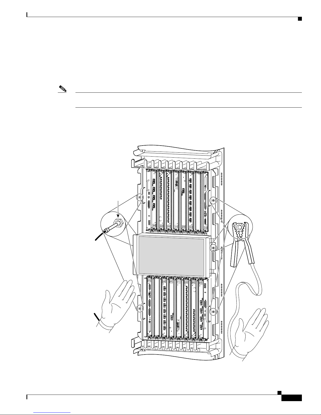
Before performing the procedures in this guide, att ach an ESD-preven tive strap to your wr ist and connect
the leash to the chassis or to another grounded, bare metal surface as shown in Figure 1.
Figure 1 Connecting an ESD-Preventive Wrist Strap to the Chassis
DOWN
LOOP RA LA
DOWN
LOOP RA LA
CDHNT CD
CDHNT CD
TX
TX
0
0
RX
RX
0
TX
TX
1
1
RX
RX
ACTIVE
CARRIER
TX
TX
RX PKT
2
2
RX
RX
TX
TX
ESD
connection
socket
1
3
ACTIVE
ACTIVE
CARRIER
RX PKT
2
ACTIVE
CARRIER
RX PKT
3
ACTIVE
CARRIER
RX PKT
Q OC-3/STM-POS
3
CARRIER
RX
RX
RX PKT
TX
TX
4
4
RX
RX
TX
TX
5
5
RX
RX
TX
6
RX
TX
7
RX
TX
8
RX
TX
9
RX
TX
10
RX
TX
11
OC-48/STM-16-SCPOS
RX
12DS3–SMB P
6DS3–SMB P
/
/
H
H
/
/
F
F
CRITICAL
MAJOR
MINOR
ACO/LT
ALARM
ENABLED
FAIL
ENABLED
FAIL
0
CSC
1
0
1
SFC
ALARM
2
Prerequisites and Preparation
EJECT
SLOT-0
0
ACTIVE
CARRIER
RX CELL
OC-12/STM-4 ATM
FAST ETERNET
SLOT-1
RESET
AUX
CONSOLE
LINK
COLL
TX
RX
MII
RJ-45
ROUTE PROCESSOR
O
O
O
O
O
O
O
O
O
O
O
O
O
O
O
O
O
O
O
O
O
O
O
O
O
O
O
O
O
O
O
O
O
O
O
O
O
O
O
O
O
O
O
O
O
O
O
O
O
O
O
O
O
O
O
O
O
O
O
O
O
O
O
O
O
O
O
O
O
O
O
O
O
O
O
O
O
O
O
O
O
O
O
O
O
O
O
O
O
O
O
O
O
O
O
O
O
ROUTE PROCESSOR
FAST ETERNET
RJ-45
MII
RX
TX
COLL
LINK
CONSOLE
AUX
RESET
SLOT-1
SLOT-0
EJECT
RX CELL
CARRIER
ACTIVE
F
F
/
/
H
H
/
/
2
ALARM
SFC
1
OC-12/STM-4 ATM
12DS3–SMB P
RX
OC-48/STM-16-SCPOS
11
TX
RX
10
TX
RX
9
TX
RX
8
TX
RX
7
TX
RX
6
TX
RX
5
TX
RX
4
TX
RX PKT
RX
CARRIER
0
3
ACTIVE
TX
RX
2
TX
RX
1
TX
RX
0
TX
CDHNT CD
LOOP RA LA
DOWN
0
6DS3–SMB P
1
CSC
Q OC-3/STM-POS
0
FAIL
ENABLED
FAIL
ENABLED
RX PKT
CARRIER
ACTIVE
3
ALARM
RX PKT
CARRIER
ACTIVE
ACO/LT
RX
5
2
TX
RX
4
RX PKT
MINOR
CARRIER
TX
MAJOR
ACTIVE
CRITICAL
RX
3
1
TX
RX
2
RX PKT
TX
CARRIER
ACTIVE
RX
1
TX
0
RX
0
TX
CDHNT CD
LOOP RA LA
DOWN
Cisco 12016, Cisco 12416, and Cisco 12816 Router Blower Module and Air Filter Replacement Instructions
78-16083-02
3
Page 4
Installation Guidelines
Installation Guidelines
The blower modules support online inser tion and remov al (O IR), so you can remo ve and install a b lower
module while the system remains powered on without presenting an electrical hazard or damage to the
system. Y ou can replace a blower module while the
session preservation.
Caution Although th e blower module support s OIR and can be replaced without interruption to system operation,
the system should not operate without a blower module for more than 3 minutes to prevent overheating.
Caution You cannot mix blower types within the chassis. If you are replacing a blower module from an old system
(GSR16-BLOWER=)
replacement blowers (12000/10/16-BLWER=). Although the blower modules can be replaced without
interruption to system operation, the system should not operate with mixed blower modules in the router
for more than 5 minutes.
system maintains all routing information and ensures
, you must replace both upper and lo wer bl ower mo dules with ne w, higher capacity
Required Tools and Equipment
You need the following tools and equipment to install the blower module:
• Number 2 Phillips screwdriver
• 3/16-inch flat-blade screwdriver
• An electrostatic discharge (ESD) preventive wrist or ankle strap with connection cord
• Vacuum cleaner (to clean the air filters)
Removing and Replacing the Blower Modules
This section contains the procedure to remove and replace the upper or lower blower modules from the
chassis. Before beginning either of these procedures, be sure to read the “Install ation Guidelines” se ction
on page 4.
Upper and Lower Blower Module Orientation
Illustrations in this procedure show the removal and replacement of the upper blower module. The
procedure to replace the lower blower module is the same except for the orientation of the blower
module.
• Heads-up orientation—Install the blo wer module in the upper bay in the “h eads-up” orientation with
the three fan air intake openings face down.
• Heads-down orientation—Install the blower module in the lower blower module bay in the
“heads-down” orientation with the three fan air intake openings face up.
Cisco 12016, Cisco 12416, and Cisco 12816 Router Blower Module and Air Filter Replacement Instructions
4
78-16083-02
Page 5
Use the following procedure to remove and replace the blower modules.
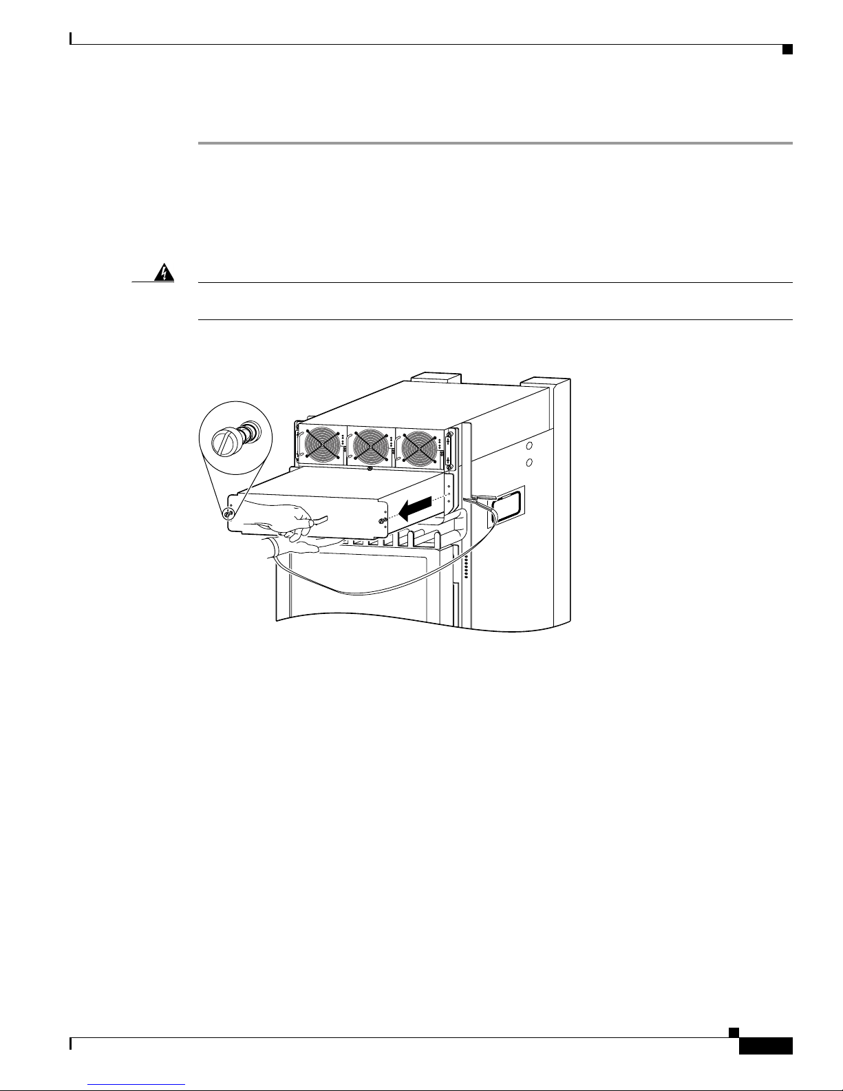
Step 1 Remove the blower module from the chassis (Figure 2):
a. Loosen the captive screw on each side of the blower module.
b. Pull out the blower module halfway from the module bay.
c. Slide out the blow er module completely from the module bay while supporting it with your other
hand.
Removing and Replacing the Blower Modules
Warning
The blower module weighs approximately 20 pounds (9 kg). Use two hands when handling the blowe r
module.
Figure 2 Removing the Upper Blower Module
PWR OK
FAULT
TEMP
I LIM
PWR OK
FAULT
TEMP
I LIM
PWR OK
FAULT
TEMP
I LIM
26213
Cisco 12016, Cisco 12416, and Cisco 12816 Router Blower Module and Air Filter Replacement Instructions
78-16083-02
5
Page 6
Removing and Replacing the Blower Modules
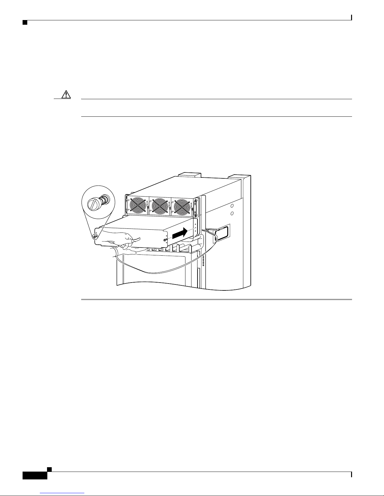
Step 2 Install the new blower module into the chassis (Figure 3):
a. Lift the blow er module (with two hands) and slide it halfway into the module bay.
b. Slowly push the blower module into the chassis until it mates with the backplane connector at the
back of the module bay.
Caution To prevent damage to the connectors, do not use excessive force when inserting the blower module into
the chassis.
c. Tighten the captive screws on the blower module to secure it to the chassis.
• The (green) OK status indicator on the front of the blower module should light. If the OK indicator
does not light, see the “Troubleshooting the Installation” section on page 7.
Figure 3 Installing the Upper Blower Module
PWR OK
FAULT
TEMP
I LIM
PWR OK
FAULT
TEMP
I LIM
PWR OK
FAULT
TEMP
I LIM
27218
Cisco 12016, Cisco 12416, and Cisco 12816 Router Blower Module and Air Filter Replacement Instructions
6
78-16083-02
Page 7

Troubleshooting the Installation
Use the following procedure to troubleshoot a blower module if it is not operating properly after
installation.
Step 1 Be sure the router is powered on and that all power cords are connected properly.
Step 2 Loosen the captive screws and reseat the blower module to the chassis.
• Retighten the captive screws to ensure the blower module is properly seated to the backplane
connector.
Step 3 Check the blower module status indicators:
• OK (green)—Indicates that the blower mod ule is operating normally. This indicator should light as
soon as the blower module is installed and receives power from the backplane connector.
–
If this indicator remains on, and the blower module fans fail to operate after several attempts to
reseat the blower module, replace it with a spare.
–
If the spare blower module also fails, power off the router and contact a Cisco service
representative for assistance.
• FAIL (red)—This indicator remains off during normal operation. If this indicator is on, the system
has detected a fan failure or other fault in the blower module.
–
If this indicator remains on, and the blower module fans fail to operate after several attempts to
reseat the blower module, replace it with a spare.
Troubleshooting the Installation
–
If the spare blower module also fails, power off the router and contact a Cisco service
representative for assistance.
Cleaning or Replacing the Chassis Air Filter
The Cisco 12016, Cisco 12416, and Cisco 12816 routers are equipped a user-serviceable air filter that
removes dust drawn into the router. One time per month (or more often in dusty environments), examine
the air filter for damage and cleanliness.
Caution Damage to the air filter can restrict the airflow, cause overheating in the router, and degrade EMI
performance. Be careful when cleaning and replacing the filter.
Cisco 12016, Cisco 12416, and Cisco 12816 Router Blower Module and Air Filter Replacement Instructions
78-16083-02
7
Page 8

Cleaning or Replacing the Chassis Air Filter
(2 on each side)
Use the following procedure to clean or replace the air filter.
Step 1 Loosen the captive screws on the air filter door and pivot the door open (Figure 4).
Caution If the router uses an extended front cover bezel, the air filter door does not have enough space to open
completely. Before you open the air filter door, you must remove the extended front cover.
Figure 4 Opening the Chassis Air Filter Door
Switch fabric
card cage
(behind filter door)
Q OC-3/STM-POS
6DS3–SMB P
/
H
/
F
RX
TX
11
RX
12DS3–SMB P
/
H
/
F
OC-48/STM-16-SCPOS
OC-12/STM-4 ATM
FAST ETERNET
ROUTE PROCESSOR
ENABLED
FAIL
0
CSC
1
0
1
SFC
ALARM
2
Air filter door
Captive screws
Air filter
26195
Cisco 12016, Cisco 12416, and Cisco 12816 Router Blower Module and Air Filter Replacement Instructions
8
78-16083-02
Page 9

Cleaning or Replacing the Chassis Air Filter
27960
a
Step 2 Lift up the air filter and carefully slide it out the door (Figure 5).
Caution Be careful not to damage the honeycomb screens on the back of the air filter door and in
the fabric card cage. Damage to the honeycomb screens can restrict airflow, cause
overheating, and affect EMI performance.
Figure 5 Removing the Chassis Air Filter
Q OC-3/STM-POS
6DS3–SMB P
/
H
/
F
RX
TX
11
RX
12DS3–SMB P
/
H
/
F
OC-48/STM-16-SCPOS
OC-12/STM-4 ATM
FAST ETERNET
ROUTE PROCESSOR
Air filter
ENABLED
FAIL
0
CSC
1
0
1
SFC
ALARM
2
Push filter up
with palm
nd fingertips
Step 3 Visually check the condition of the air filter to determine whether to clean or install a new replacement.
• Dirty—You can vacuum or replace the filter.
Caution Do not v acuum the air fil ter while it is installed in the chassi s. You must remove the air filter completely
before you clean it to prevent contaminants from being drawn into the bays or cage.
• Worn or torn—If the filter appears worn or torn, dispose of it in a responsible manner and install a
replacement air filter (ACS-GSR16-FLTR=).
Cisco 12016, Cisco 12416, and Cisco 12816 Router Blower Module and Air Filter Replacement Instructions
78-16083-02
9
Page 10

Cleaning or Replacing the Chassis Air Filter
27966
A
Step 4 Position the metal braces on the back of the air filter to face toward the switch fabric and alarm card
cage. Slide the new or cleaned air filter into the air filter door (Figure 6).
Figure 6 Installing the Chassis Air Filter
Air filter
ir filter door
Q OC-3/STM-POS
6DS3–SMB P
/
H
/
F
RX
TX
11
RX
12DS3–SMB P
/
H
/
F
OC-48/STM-16-SCPOS
OC-12/STM-4 ATM
FAST ETERNET
ROUTE PROCESSOR
ENABLED
FAIL
0
CSC
1
0
1
SFC
ALARM
2
Cisco 12016, Cisco 12416, and Cisco 12816 Router Blower Module and Air Filter Replacement Instructions
10
78-16083-02
Page 11

Cleaning or Replacing the Chassis Air Filter
(
w
s
e)
Step 5 Lift up the air filter door so that the four guide pins are inserted in the corresponding holes on each side
of the switch fabric card cage (Figure 7).
Caution Align and seat th e door carefully to a v oid damaging the EMI-pre ven tiv e gask et contacts on
the door.
Figure 7 Closing the Chassis Air Filter Door
Q OC-3/STM-POS
6DS3–SMB P
/
H
/
F
11
RX
TX
RX
12DS3–SMB P
/
H
/
F
OC-48/STM-16-SCPOS
OC-12/STM-4 ATM
FAST ETERNET
ROUTE PROCESSOR
ENABLED
FAIL
0
CSC
1
0
1
SFC
ALARM
2
Switch fabric
card cage
Guide pin
behind filter door)
Air filter
door
Air filter
Captive scre
Captive screw
(2 on each sid
27962
Step 6 Tighten the captive screws to secure the door to the chassis.
Caution The air filter door must be closed and secured at all times to maintain correct
EMI performance.
Cisco 12016, Cisco 12416, and Cisco 12816 Router Blower Module and Air Filter Replacement Instructions
78-16083-02
11
Page 12

Regulatory, Compliance, and Safety Information
Regulatory, Compliance, and Safety Information
This section includes regulatory, compliance, and safety information.
Translated Safety Warnings and Agency Approvals
The complete list of translated safety warnings and agency approvals is available in the Regulatory
Compliance and Safety Information for Cisco 12016, Cisco 12416, and Cisco 12816 Series routerss
publication (PN 78-4347-xx).
Electromagnetic Compatibility Regulatory Statements
FCC Class A Compliance
This equipment has been tested and found to comply with the limits for a Class A di gital device, pursuant
to part 15 of the FCC rules. These limits are designed to provide reasonable protection against harmful
interference when the equipment is operated in a commercial environment. This equipment generates,
uses, and can radiate radio-frequency energy and, if not installed and used in accordance with the
instruction manual, may cause harmful interference to radio communications. Operation of this
equipment in a residential area is likely to cause harmful interference, in which case users will be
required to correct the interference at their own expense.
CISPR 22
Modifying the equipment without Cisco authorizatio n may result in th e equipment no longer complyi ng
with FCC requirements for Class A digital devices. In that event, your right to use the equipment may
be limited by FCC regulation and you may be required to correct any interference to radio or television
communication at your own expense.
You can determine whether your equipment is causing interference by turning it off. If the interference
stops, it was probably caused by the Cisco equipment or one of its peripheral devices. If the equipment
causes interference to radio or television reception, try to correct the interference by using one or more
of the following measures:
• Turn the television or radio antenna until the interference stops.
• Move the equipment to one side or the other of the television or radio.
• Move the equipment farther away from the television or radio.
• Plug the equipment into an outlet that is on a different circuit from the television or radio. (That is,
make certain the equipment and the television or radio are on circuits co ntroll ed b y different circuit
breakers or fuses.)
This apparatus complies with CISPR 22/EN55022 Class B radiated and conducted emissions
requirements.
Cisco 12016, Cisco 12416, and Cisco 12816 Router Blower Module and Air Filter Replacement Instructions
12
78-16083-02
Page 13

Canada
English Statement of Compliance
This class A digital apparatus complies with Canadian ICES-003.
French Statement of Compliance
Cet appareil numérique de la classe A est conforme à la norme NMB-003 du Canada.
Europe—EU
This apparatus complies with EN55022 Class B and EN55024 standards when used as ITE/TTE
equipment, and EN300386 for Telecommunications Network Equipment (TNE) in both installation
environments, telecommunication centers and other indoor locations.
VCCI Class A Notice for Japan
Regulatory, Compliance, and Safety Information
Warning
This is a Class A product based on the standard of the Voluntary Control Council for Interference by
Information Technology Equipment (VCCI). If this equipment is used in a domestic environment, radio
disturbance may arise. When such trouble occurs, the user may be required to take corrective
actions.
Statement 191
Class A Notice for Hungary
Warning
This equipment is a class A product and should be used and installed properly according to the
Hungarian EMC Class A requirements (MSZEN55022). Class A equipment is designed for typical
commercial establishments for which special conditions of installation and protection distance are
Statement 256
used.
Cisco 12016, Cisco 12416, and Cisco 12816 Router Blower Module and Air Filter Replacement Instructions
78-16083-02
13
Page 14

Obtaining Documentation
Class A Notice for Taiwan and Other Traditional Chinese Markets
Warning
This is a Class A Information Product, when used in residential environment, it may cause radio
frequency interference, under such circumstances, the user may be requested to take appropriate
countermeasures.
Statement 257
Class A Notice for Korea
Warning
This is a Class A Device and is registered for EMC requirements for industrial use. The seller or buyer
should be aware of this. If this type was sold or purchased by mistake, it should be replaced with a
residential-use type.
Statement 294
Obtaining Documentation
Cisco provides several ways to obtain documentation, technical assistance, and other technical
resources. These sections explain how to obtain technical information from Cisco Systems.
Cisco.com
Cisco 12016, Cisco 12416, and Cisco 12816 Router Blower Module and Air Filter Replacement Instructions
14
You can access the most current Cisco documentation on the World Wide Web at this URL:
http://www.cisco.com/univercd/home/home.htm
You can access the Cisco website at this URL:
http://www.cisco.com
International Cisco websites can be accessed from this URL:
http://www.cisco.com/public/countries_languages.shtml
78-16083-02
Page 15

Ordering Documentation
You can find instructions for ordering documentation at this URL:
http://www.cisco.com/univercd/cc/td/doc/es_inpck/pdi.htm
You can order Cisco docu mentation i n these ways:
• Registered Cisco.com users (Cisco direct customers) can order Cisco product documentation from
the Networking Products MarketPlace:
http://www.cisco.com/en/US/partner/ordering/index.shtml
• Nonregistered Cisco.com users can order documentation through a local account representative by
calling Cisco Systems Corporate Headquarters (California, USA.) at 408 526-7208 or, elsewh ere in
North America, by calling 800 553-NETS (6387).
Documentation Feedback
You can submit comments electronically on Cisco.com. On the Cisco Documentation home page, click
Feedback at the top of the page.
You can send your comments in e-mail to bug-doc@cisco.com.
Obtaining Technical Assistance
You can submit comments by using the response card (if present) behind the front cover of your
document or by writing to the following address:
Cisco Systems
Attn: Customer Document Ordering
170 West Tasman Drive
San Jose, CA 95134-9883
We appreciate your comments.
Obtaining Technical Assistance
For all customers, partners, resellers, and distributors who ho ld valid Cisco service contracts, the Cisco
T echnical Assistance Center (TAC) provides 24-hour , award-winning technical support services, online
and over the phone. Cisco.com features the Cisco TAC website as an online starting point for technical
assistance.
Cisco TAC Website
The Cisco TAC website (http://www.cisco.com/tac) provides online documents and tools for
troubleshooting and resolving technical issues with Cisco products and technologies. The Cisco TAC
website is available 24 hours a day, 365 days a year.
Accessing all the tools on the Cisco TAC website requires a Cisco.com user ID and password. If you
have a valid service contract but do not have a login ID or password, register at this URL:
http://tools.cisco.com/RPF/register/register.do
Cisco 12016, Cisco 12416, and Cisco 12816 Router Blower Module and Air Filter Replacement Instructions
78-16083-02
15
Page 16

Obtaining Additional Publications and Information
Opening a TAC Case
The online TAC Case Open Tool (http://www.cisco.com/tac/caseopen) is the fastest way to open P3 and
P4 cases. (Your network is minimally impaired or you require product information). After you describe
your situation, the T A C Case Open T o ol automatically recommends resources for an immediate solution.
If your issue is not resolved using these recommendations, your case will be assigned to a Cisco TAC
engineer.
For P1 or P2 cases (your production netw ork is do wn or sev erely degraded) or if you do not ha ve Internet
access, contact Cisco TAC by telephone. Cisco TAC engineers are assigned immediately to P1 and P2
cases to help keep your business operations running smoothly.
To open a case by telephone, use one of the following numbers:
Asia-Pacific: +61 2 8446 7411 (Australia: 1 800 805 227)
EMEA: +32 2 704 55 55
USA: 1 800 553-2447
For a complete listing of Cisco TAC contacts, go to this URL:
http://www.cisco.com/warp/public/687/Directory/DirTAC.shtml
TAC Case Priority Definitions
T o ensure that all case s are r eported in a sta ndard fo rmat, Ci sco has establis hed ca se pri ority definitions.
Priority 1 (P1)—Your network is “down” or there is a critical impact to your business operations. You
and Cisco will commit all necessary resources around the clock to resolve the situation.
Priority 2 (P2)—Operation of an existing network is severely degraded, or significant aspects of your
business operation are negatively affected by inadequate performance of Cisco produ cts. You and Cisco
will commit full-time resources during normal business hours to resolve the situation.
Priority 3 (P3)—Operational performance of your network is impaired, but most business operations
remain functional. You and Cisco will commit resources during normal business hours to restore service
to satisfactory levels.
Priority 4 (P4)—You require information or assistance with Cisco product capabilities, installation, or
configuration. There is little or no effect on your business operations.
Obtaining Additional Publications and Information
Information about Cisco products, technologies, and network solu tio ns is available from various onl in e
and printed sources.
• The Cisco Product Catalog describes the networki ng products o f fered b y Cisco Systems, as well as
ordering and customer support services. Access the Cisco Product Catalog at this URL:
http://www.cisco.com/en/US/products/products_catalog_links_launch.html
• Cisco Press publishes a wide range of networking publications. Cisco suggests these titles for new
and experienced users: Internetworking Terms and Acronyms Dictionary, Internetwo rking
Technology Handbook, Internetworking Troubleshooting Guide, and the Internetworking De sign
Guide. For current Cisco Press titles and other information, go to Cisco Press online at this URL:
http://www.ciscopress.com
Cisco 12016, Cisco 12416, and Cisco 12816 Router Blower Module and Air Filter Replacement Instructions
16
78-16083-02
Page 17

Obtaining Additional Publications and Information
• Packet magazine is the Cisco quarterly publication that provides the latest networking trends,
technology breakthroughs, and Cisco products and s olutions to help industry professionals get the
most from their networking investment. Included are networking deployment and troubleshooting
tips, configuration examples, customer case studies, tutorials and training, certif ication information,
and links to numerous in-depth online resources. You can access Packet magazine at this URL:
http://www.cisco.com/go/packet
• iQ Magazine is the Cisco bimonthly publication that delivers the latest information about Internet
business strategies for executives. You ca n access iQ Magazine at this URL:
http://www.cisco.com/go/iqmagazine
• Internet Protocol Journal is a quarterly journal published by Cisco Systems for engineering
professionals involved in designing, developing, and operating public and private internets and
intranets. You can ac cess the Internet Protocol Journal at this URL:
http://www.cisco.com/en/US/about/ac123/ac147/about_cisco_the_internet_protocol_journal.html
• Training—Cisco offers world-class networking training. Current offerings in network training are
listed at this URL:
http://www.cisco.com/en/US/learning/le31/learning_recommended_training_list.html
Cisco 12016, Cisco 12416, and Cisco 12816 Router Blower Module and Air Filter Replacement Instructions
78-16083-02
17
Page 18

Obtaining Additional Publications and Information
This document is to be used in conjunction with the Cisco 12016, Cisco 12416, and Cisco 12816 Router Installation and Configuration Guide.
CCVP, the Cisco logo, and the Cisco Square Bridge logo are trademarks of Cisco Systems, Inc.; Changing the Way We Work, Live, Play, and Learn is a
service mark of Cisco Systems, Inc.; and Access Registrar, Aironet, BPX, Catalyst, CCDA, CCDP, CCIE, CCIP, CCNA, CCNP, CCSP, Cisco, the Cisco
Certified Internetwork Expert logo, Cisco IOS, Cisco Press, Cisco Systems, Cisco Systems Capital, the Cisco Systems logo, Cisco Unity,
Enterprise/Solver, EtherChannel, EtherFast, EtherSwitch, Fast Step, Follow Me Browsing, FormShare, GigaDrive, HomeLink, Internet Quotient, IOS,
iPhone, IP/TV, iQ Expertise, the iQ logo, iQ Net Readiness Scorecard, iQuick Study, LightStream, Linksys, MeetingPlace, MGX, Networking Academy,
Network Registrar, PIX, ProConnect, ScriptShare, SMARTnet, StackWise, The Fastest Way to Increase Your Internet Quotient, and TransPath are
registered trademarks of Cisco Systems, Inc. and/or its affiliates in the United States and certain other countries.
All other trademarks mentioned in this document or Website are the property of their respective owners. The use of the word partner does not imply a
partnership relationship between Cisco and any other company. (0709R)
Copyright © 2005 Cisco Systems, Inc. All righ ts reserved.
Cisco 12016, Cisco 12416, and Cisco 12816 Router Blower Module and Air Filter Replacement Instructions
18
78-16083-02
 Loading...