

Page 1

Cisco 11500 Series
Content Services Switch
Hardware Installation Guide
Software Version 7.10
December, 2002
Corporate Headquarters
Cisco Systems, Inc.
170 West Tasman Drive
San Jose, CA 95134-1706
USA
http://www.cisco.com
Tel: 408 526-4000
800 553-NETS (6387)
Fax: 408 526-4100
Customer Order Number: DOC-7813884=
Text Part Number: 78-13884-03
Page 2

THE SPECIFICATIONS AND INFORMATION REGARDING THE PRODUCTS IN THIS MANUAL ARE SUBJECT TO CHANGE WITHOUT
NOTICE. ALL STATEMENTS, INFORMATION, AND RECOMMENDATIONS IN THIS MANUAL ARE BELIEVED TO BE ACCURATE BUT
ARE PRESENTED WITHOUT WARRANTY OF ANY KIND, EXPRESS OR IMPLIED. USERS MUST TAKE FULL RESPONSIBILITY FOR
THEIR APPLICATION OF ANY PRODUCTS.
THE SOFTWARE LICENSE AND LIMITED WARRANTY FOR T HE A CCOMPANYING PRODUCT ARE SET FOR TH IN T HE INFORMATION
PACKET THAT SHIPPED WITH THE PRODUCT AND ARE INCORPORATED HEREIN BY THIS REFERENCE. IF YOU ARE UNABLE TO
LOCATE THE SOFTWARE LICENSE OR LIMITED WARRANTY, CONTACT YOUR CISCO REPRESENTATIVE FOR A COPY.
The following information is for FCC compliance of Class A devices: This equipment has been tested and found to comply with the limits for a Class
A digital device, pursuant to part 15 of the FCC rules. These limits are designed to provide reasonable protection against harmful interference when
the equipment is operated in a commercial environment. This equipment generates, uses, and can radiate radio-frequency energy and, if not installed
and used in accordance with the instruction manual, may cause harmful interference to radio communications. Operation of this equipment in a
residential area is likely to cause h armful interference, in which case users will be required to correct the interference at their own expense.
The following information is for FCC comp liance of Cl ass B devices: The equipm ent descr ibed in thi s manual gener ates and may radi ate
radio-frequency energy. If it is not installed in accordance with Cisco’s installation instructions, it may cause interference with radio and television
reception. This equipment has been tested and found to comply with the limits for a Class B digital device in accordance with the specifications in
part 15 of the FCC rules. These specifications are designed to provide reasonable protection against such interference in a residential installation.
However, there is no guarantee that interference wi ll not occur in a particular installation.
Modifying the equipm ent wit hout C isco’s written autho rizatio n may re sul t in the equipm ent no lon ger comply ing with FC C re quirem ents for Class
A or Class B digital devices. In that event, your right to use the equ ipment m ay be limit ed by FCC regulati ons, and yo u may be r equi red t o correct
any interference to radio or television communi cations at you r own expense.
You can det ermine wh ether your equipmen t is causing interf erence by turning it off. If the interference stop s, it was probabl y caused by the Cisco
equipment or one of its peripheral devices. If the equipment causes interference to radio or television reception, try to correct the interference by
using one or more of the following measures :
• Turn the television or radio antenna until the interfe rence stops .
• Move the equipment to one side or the other of the te levision or radio .
• Move the equipment farther away from the television or radio.
• Plug the equipment into an outlet that is on a different circuit from the television or radio. (That is , make certain the equi pment and the television
or radio are on circuits controlled by different circuit br eakers or fuses.)
Modifications to this product no t authori zed by Cisco Syst ems, Inc. could void the FCC app roval and negate your authori ty to oper ate the product.
The Cisco implementation of TCP header com pression i s an adap tati on o f a pr ogr am d eveloped by the University of California, Berkeley (UCB) as
part of UCB’s public domain version of the UNIX operating system. All rights reserved. Copyright © 1981, Regents of the University of California.
NOTWITHSTANDIN G ANY OTHER WA RRANTY HEREIN, AL L DOCUMENT FILE S AND SOFTWARE OF THESE SUPPLIERS ARE
PROVIDED “AS IS” WITH ALL FAULTS. CISCO AND THE ABOVE-NAMED SUPPLIERS DISCLAIM ALL WARRANTIES, EXPRESSED
OR IMPLIED, INCLUDING, WITHOUT LIMITATION, THOSE OF MERCHANTABILITY, FITNESS FOR A PARTICU LAR PURPOSE AND
NONINFRINGEMENT OR ARISING FROM A COURSE OF DEALING, USAGE, OR TRADE PRACTICE.
IN NO EVENT SHALL CISCO OR ITS SUPPLIERS BE LIABLE FOR ANY INDIRECT, SPECIAL, CONSEQUENTIAL, OR INCIDENTAL
DAMAGES, INCLUDING, WITHOUT LIMITATION, LOST PROFITS OR LOSS OR DAMAGE TO DATA ARISING OUT OF THE USE OR
INABILITY TO USE THIS MANUAL, EVEN IF CISCO OR ITS SUPPLIERS HAVE BEEN ADVISED OF THE POSSIBILITY OF SUCH
DAMAGES.
Page 3

CCIP, the Cisco Arrow logo, the Cisco Powered Network mark, the Cisco Systems Verified logo, Cisco Unity, Follow Me Browsing, FormShare, iQ
Breakthrough, iQ Expertise, iQ FastTrack, the iQ Logo, iQ Net Readiness Scorecard, Networking Academy, ScriptShare, SMARTnet, TransPath, and
Voice LAN are trademarks of Cisco Systems, Inc.; Changing the Way We Work, Live, Play, and Learn, Discover All That’s Possible, The Fastest Way to
Increase Your Internet Quotient, and iQuick Study are service marks of Cisco Systems, Inc.; and Aironet, ASIST, BPX, Catalyst, CCDA, CCDP, CCIE,
CCNA, CCNP, Cisco, the Cisco Certified Internetwork Expert logo, Cisco IOS, the Cisco IOS logo, Cisco Press, Cisco Systems, Cisco Systems Capital,
the Cisco Systems logo, Empowering the Internet Generation, Enterprise/Solver, EtherChannel, EtherSwitch, Fast Step, GigaStack, Internet Quotient,
IOS, IP/TV, LightStream, MGX, MICA, the Networkers logo, Network Registrar, Packet, PIX, Post-Routing, Pre-Routing, RateMUX, Registrar,
SlideCast, StrataView Plus, Stratm, SwitchProbe, TeleRouter, and VCO are registered trademarks of Cisco Systems, Inc. and/or its affiliates in the U.S.
and certain other countries.
All other trademarks mentioned in this document or Web site are the property of their respective owners. The use of the word partner does not imply a
partnership relationship between Cisco and any other company. (0208R)
Cisco 11500 Series Content Ser vices Swit ch Hardware Installation Guide
Copyright © 2002, Cisco Sys tems, Inc.
All rights reserved.
Page 4

Page 5

About This Guide xvii
Audience xvii
How to Use This Guide xviii
Related Documentation xix
Symbols and Conve ntions xxi
Obtaining Documentation xxiv
World Wide Web xxiv
Documentation CD-ROM xxv
Ordering Documentation xxv
Documentation Feedback xxv
Obtaining Technical Assistance xxvi
Cisco.com xxvi
CONTENTS
CHAPTER
78-13884-03
Technical Assistance Center xxvi
Cisco TAC Web Si te xxvii
Cisco TAC Escalation Center xxviii
1 Unpacking and Installing the CSS 1-1
Site Requirements 1-2
Safety Guidelines 1-2
Chassis-Li fting Guidelines for the CSS 11503 and CSS 11506 1-3
Electrical Safety 1-4
Specificat ions for Cisco 11500 Series Power Supplies 1-6
Power Guidelines for DC Systems (CSS 11503 and CSS 11506) 1-7
Required Tools and Equipment 1-7
Cisco 11500 Series Content Services Switch Hardware Installation Guide
v
Page 6

Contents
Shipment Contents 1-8
Unpacking the CSS 1-9
Unpacking the CSS 11501 1-9
Unpacking the CS S 11503 or CSS 11506 1-9
If the Product is Damaged 1-10
Preinstallation Requirements 1-11
Installing the CSS 11501 1-12
Installing a CSS 11501 as a Freestanding Unit 1-12
Installing a CSS 11501 as a Rackmounted Unit 1-13
Installing the CSS 11503 1-14
Installing a CSS 11503 as a Freestanding Unit 1-14
Installing a CSS 11503 as a Rackmounted Unit 1-15
CHAPTER
Installing the CSS 11506 1-17
Mid-Mounting the CSS 11506 Mounting Brackets 1-18
Rack-Mounting the CSS 11506 Chassis 1-19
Installing a CSS Module 1-19
Installation Precautions and Restrictions 1-20
Installation Precautions 1-20
Module Slot Restrictions 1-21
Unpacking a CSS Modul e 1-24
Installing a Module 1-24
Installing a Pa ssive SCM in a CSS 11506 1-26
2 Cabling the CSS 2-1
Cabling the CSS 11 501 2-2
CSS 11501 Connectors and LEDs 2-4
Cabling the CSS 11 503 and CSS 11506 Modules 2-7
CSS 11503 and CSS 11506 Module Overview 2-7
Switch Control Mo dule Connectors and LEDs 2-11
Cisco 11500 Series Content Services Switch Hardware Installation Guide
vi
78-13884-03
Page 7

Fast Ethernet Mo dule Connectors and LEDs 2-14
Gigabit Ethernet Module Connectors and LEDs 2-16
Session Accelerator Module LEDs 2-18
Secure Socket Layer (SSL) Module LEDs 2-19
Connecting the Console 2-21
Connecting the Chassis to Ground 2-22
Tools and Supplies 2-22
Attaching the Grounding Cable 2-24
Connecting the Power Cord 2-26
Connecting a CSS 1 1501 Power Cord 2-26
Connecting a CSS 1 1503 Power Cord 2-27
Connecting a CSS 11 503 AC Power Cord 2-27
Contents
CHAPTER
Connecting a CSS 11 503 DC Power Cord 2-28
Connecting a CSS 1 1506 Power Cord 2-31
Connecting a CSS 11 506 AC Power Cord 2-31
Connecting a CSS 11 506 DC Power Cord 2-33
Checking the DC Po wer Connection (CSS 11503 and CSS 11506) 2-36
3 Booting and Configuring the CSS 3-1
Powering Up the CSS 3-1
Powering Down the CSS 3-2
Booting the CSS f or the First Time 3-2
Hardware Initialization and Power-On Diagnostics 3-3
Entering Your License Key 3-5
Configuring the Ethernet Management Port 3-6
Changing the Default Username and Password 3-7
Password-Protecting the Offline Diagnostic Monitor Menu 3-8
Logging in to the CSS 3-9
78-13884-03
Cisco 11500 Series Content Services Switch Hardware Installation Guide
vii
Page 8

Contents
Using the Confi guration Script 3-10
Configuring Layer 3 Load Balancing 3-12
Configuring Layer 5 Load Balancing 3-14
Configuring Proxy Cache 3-16
Configuring Transparent Cache 3-18
Where to Go Next 3-21
APPENDIX
A Specifications A-1
Electrical Specifications A-2
Environmental Specifications A-3
Physical Specifications A-4
Module Specifications A-5
Disk Specifications A-5
Supported Standards A-6
Transport A-6
Network A-6
Routing A-7
Gateway A-7
Application A-7
Network Utilities A-7
Network Management A-8
APPENDIX
B Cable Connector Pinouts B-1
RJ-45 Fast Ethernet Connector Pinouts B-2
RJ-45 RS-232 Console Port Pinouts B-3
Connecting the Console Port to a PC B-4
Connecting the Console Port to a Terminal B-5
Connecting the Console Port to a Mod em B-6
RJ-45 Management Connector Pinout s B-7
Cisco 11500 Series Content Services Switch Hardware Installation Guide
viii
78-13884-03
Page 9

Contents
APPENDIX
C Troubleshooting C-1
Troubleshooting the Boot Process C-2
Diagnostic Tests for Hardware C-2
OffDM Verification of the Boot Configuration Record and Disk C-7
Errors in the Boot Configuration Record C-7
Failure of the Disk Drive in the SCM C-8
CSS 11501 Boot and Verification C-8
SCM Boot and Verification of the Modules C-9
Troubleshooting the Console Interface C-10
Troubleshooting the CSS Power Supply C-11
Troubleshoo ting the CSS 11501 Power Supply C-11
Troubleshoo ting the CSS 11503 Power Supply C-12
Troubleshoo ting the CSS 11506 Power Supply C-12
Troubleshooting the CSS Fans C-16
Troubleshooting the CSS 11501 Chassis Fans C-16
APPENDIX
Troubleshooting the CSS 11503 Chassis Fans C-17
Troubleshoo ting the CSS 11506 Fan Module C-18
Troubleshooting the CSS 11501 C-19
Troubleshooting the CSS Modules C-21
Log File Information C-24
D Regulatory Compliance and Safety Information for the Cisco 11500 Series
Content Services Switch
D-1
Agency Approvals D-2
FCC Class A Compliance Notice (United States) D-3
FCC Compliance Information Statement (United States) D-4
ICES-003 Clas s A Compliance Notice (Canada) D-5
Europe (EU) D-5
CISPR 22 Class A Warning D-5
78-13884-03
Cisco 11500 Series Content Services Switch Hardware Installation Guide
ix
Page 10

Contents
VCCI Class A Warning D-6
Class A Notice for Taiwan and Other Traditional Chinese Markets D-8
Class A EMC Warning D-8
Safety Requirements D-9
Laser Safety D-10
Translated Sa fety Warnings D-11
Warning Definition D-11
Lithium Batt ery Disposal W a rn in g D-13
Radiation from Open Port Aperture War ning D-14
Class 1 Laser Pro duct Warning D-16
Qualified Personnel Warning D-16
Two-Pers o n Li fting Warning D-17
Lightning Activity Warning D-19
Jewelry Rem o va l W a rn in g D-20
Reading Instructions Warn ing D-21
Disconnect Device Warning D-22
Chassis Installation Warning D-23
Ground Conducto r Warning D-25
Installatio n and Replacement Warning D-26
Use Copper Conduc tors Only D-27
Short-Circuit Protection Warning D-28
Wire Preparation Warning D-29
DC Power Sou rc e Warning D-31
Dual Power Supply Warning D-33
DC Power Supply Wiring Warning D-34
Blank Faceplate Requirement Warning D-36
Power Off Bef or e W o rk in g on Sy st em W a rn in g D-38
Cisco 11500 Series Content Services Switch Hardware Installation Guide
x
78-13884-03
Page 11

I
NDEX
Contents
Fan Injury Warning D-39
AC and DC Power Module Warning D-40
Power Cord Warn ing (other versions available) D-41
Ground Conducto r Warning D-42
78-13884-03
Cisco 11500 Series Content Services Switch Hardware Installation Guide
xi
Page 12

Contents
Cisco 11500 Series Content Services Switch Hardware Installation Guide
xii
78-13884-03
Page 13

FIGURES
Figure 1-1 Front-Mounting the Mounting Brackets on the CSS 11501 1-13
Figure 1-2 Front-Mounting the Mounting Brackets on the CSS 11503 1-15
Figure 1-3 Mid-Mounting the Mounting Brackets on the CSS 11503 1-16
Figure 1-4 Front-Mounting Position of the CSS 11506 Mounting Brackets 1-17
Figure 1-5 Mid-Mounting the Mounting Brackets on the CSS 11506 1-18
Figure 1-6 Fully-Configured CSS 11503 1-22
Figure 1-7 Fully-Configured CSS 11506 1-23
Figure 1-8 Installing a Module into a CSS Chassi s 1-25
Figure 1-9 Installing a PCMCIA Cover on an SCM 1-27
Figure 2-1 CSS 11501 Connect ors and LEDs 2-4
Figure 2-2 CSS 11503 Content Services Switch 2-9
Figure 2-3 CSS 11506 Content Services Switch 2-10
Figure 2-4 Switch Control Mo dule Connectors and LEDs 2-12
Figure 2-5 8-Port Fast Et hernet Module Conn ectors and LEDs 2-14
Figure 2-6 16-Port Fas t Et he rnet Module Co nn ectors and LED s 2-15
Figure 2-7 Gigabit Ethernet Module Connectors and LEDs 2-17
Figure 2-8 Session Accelerator Module LEDs 2-18
Figure 2-9 SSL Module LE Ds 2-20
Figure 2-10 Attaching Gro unding Wire to Grounding Lug 2-25
Figure 2-11 Connecting a CSS 1 1501 AC Power Cord 2-26
Figure 2-12 Connecting a CSS 1 1503 AC Power Cord 2-27
Figure 2-13 Location of th e CSS 11503 DC Power Supply Connectors 2-29
Figure 2-14 Connecting a CSS 1 1506 AC Power Cord 2-32
Cisco 11500 Series Content Services Switch Hardware Installation Guide
78-13884-03
xiii
Page 14

Figures
Figure 2-15 Location of CSS 11506 DC Power Supply Connectors 2-34
Figure C-1 Location of th e CSS 11506 Power Supplies C- 1 3
Figure C-2 CSS 11506 AC Power Supply LEDs C-14
Figure C-3 CSS 11506 DC Power Supply LEDs C-14
Cisco 11500 Series Content Services Switch Hardware Installation Guide
xiv
78-13884-03
Page 15

Table 1-1 AC Electrica l Specifications 1-6
Table 1-2 DC Electrica l Specifications 1-6
Table 1-3 CSS 11503 Chassis Slot Restriction 1-21
Table 1-4 CSS 11506 Chassis Slot Restriction 1-21
Table 2-1 CSS 11501 LED Descriptions 2-5
Table 2-2 Switch Control Mo dule LED Descriptions 2-13
Table 2-3 Fast Ethernet Mo dule LED Descriptions 2-16
Table 2-4 Gigabit Ethernet Module LED Descriptions 2-17
Table 2-5 Session Accelerator Module LED Descriptions 2-19
Table 2-6 SSL Module LED Descriptions 2-20
Table 2-7 CSS Console Port Default Settin gs 2-21
Table 2-8 Tools and Supplies 2-22
TABLES
Table 2-9 CSS 11503 to DC Power Source Cabling 2-30
Table 2-10 CS S 11506 to DC Power Source Cabling 2-35
Table 3-1 Status LEDs Boot Definitions 3-4
Table A-1 AC Electrica l Specifications A-2
Table A-2 DC Electrica l Specifications A-2
Table A-3 Environmental Specifications A-3
Table A-4 Physical Specifications A-4
Table A-5 Module Specifications A-5
Table A-6 Disk Specifications A-5
Table B-1 RJ-45 Fast Ethernet Connector Pinouts B-2
Table B-2 RJ-45 RS-232 Serial Connector Pi nouts for the Console Port B-3
Cisco 11500 Series Content Services Switch Hardware Installation Guide
78-13884-03
xv
Page 16

Tables
Table B-3 Console Port to PC Signals and Pinout s B-4
Table B-4 Console Port to Terminal Signals and Pinouts B-5
Table B-5 Console Port to Modem Signals and Pinouts B-6
Table B-6 RJ-45 Management Connector Pinouts B-7
Table C-1 Fields in the D ia gn ostic Monito r Er ror Message C-4
Table C-2 Troubleshooting the Consol e Interface C-10
Table C-3 LEDs of the CSS 11506 Power Supply C-15
Table C-4 Troubleshooting the CSS 11501 C-19
Table C-5 Troubleshooting the CSS Modules C-22
Table C-6 CSS Log File Descr iptions C-24
Table D-1 Regulatory Approval Requirements D-2
Cisco 11500 Series Content Services Switch Hardware Installation Guide
xvi
78-13884-03
Page 17

Audience
About This Guide
This guide is intended to help you install your Cisco 11500 series content services
switch (hereinafter referred to as the CSS) and get it into operation. It provides
you with instructions for installing, c abling, boo ting, and configuring the CSS
using the configurat ion scri pt.
78-13884-03
Warning
Only trained and qualified personnel are allowed to install or replace this
equipment.
This guide is intended for the following trained and qualified service personnel
who are responsible for installi ng and operat ing the CSS:
• System installer
• Hardware te ch ni cia n
• System operator
Cisco 11500 Series Content Services Switch Hardware Installation Guide
xvii
Page 18

How to Use This Guide
How to Use This Guide
This section describes the chapters and contents in this guide.
Chapter/Appendix Description
About This Guide
Chapter 1,
Unpacking a nd
Installing the CSS
Chapter 2,
Cabling the CSS
Chapter 3,
Booting and
Configuring the CSS
Appendix A,
Specifications
Appendix B,
Cable Connect or
Pinouts
Appendix C,
Troubleshooting
This chap ter pr ovides i n struc tio ns for u npa ck ing an d
installing the CSS.
This chapte r descri bes t h e CSS 1 150 1 in tegrate d
platform and the CSS 11503 a nd 11506 mod ular
platforms, including LEDs and connectors. This chapter
also provides instructions for connecting the console and
power cords.
This chapter provides infor matio n on powering and
booting the CSS for the first time. This chapter also
describes how to configure the CSS using the
configuration script.
This appendix provides spec ifications for the CSS and its
components.
This appendix provides pinouts for each connector on the
CSS.
This appendi x pr ovides t roubl es hoot ing i nfo rma tio n fo r
the CSS, power supply, and the boot process.
Appendix D,
Regulatory
Compliance and
Safety Informa tion
for the Cisco 11500
Series Content
Services Switch
Cisco 11500 Series Content Services Switch Hardware Installation Guide
xviii
This appendix provides information on regulatory
compliance an d safety perta ining to the CSS.
78-13884-03
Page 19

About This Guide
Related Documentation
In addition to this document, the content services switch documentation set
includes the following publications:
Document Title Description
Related Do cu m entation
Release Note for the Cisco
11500 Series Conte nt
Services Switch
Cisco Conten t Se rvice s
Switch Administration
Guide
This release note provides in format ion on
operating c onsid er ati ons , caveats, and CL I
commands for th e Cisco 11 500 serie s C SS.
This guide d esc ribes how to pe rf orm
administration tasks on the CSS including logging
into the CSS, upgr adin g y our C SS sof tware, a nd
configuring the following:
• Management ports, interfaces, and circuits
• DNS, ARP, RIP, IP, and bridging features
• OSPF
• Logging, includi ng disp laying log m essages
and interpreting sys.log me ssages
• User profile and CSS parameters
• SNMP
• RMON
• Offline Diagnostic Monitor (Offline DM)
menu
78-13884-03
Cisco 11500 Series Content Services Switch Hardware Installation Guide
xix
Page 20

Related Documentation
About This Guide
Document Title Description
Cisco Conten t Se rvice s
Switch Basic
Configuration Guide
Cisco Conten t Se rvice s
Switch Advanc ed
Configuration Guide
This guide descri bes how to perf orm basic C SS
configuration tasks, i ncl uding :
• Services
• Owners
• Conten t ru les
• Sticky parameters
• HTTP header load balancing
• Source groups, Access Cont rol Lists (ACLs) ,
Extension Qualifier Lists (EQLs), Uniform
Resource Locator Q ualifi er Lists (URQL s),
Network Qualifier Lists (NQLs), and Domain
Qualifier Lists (DQLs)
• Caching
This guide describes how to perform advanced CSS
configuration tasks, i ncl uding :
• Domain Name Service (DNS)
• DNS Sticky
• Conten t Rou tin g Ag ent
• Client Side Accelerator
• Network proximity
• VIP and virtual IP interfac e redundancy
• Box-to-box red und ancy
• Demand-based content replication and content
staging and replica tion
• Secure Socket Layer (SSL) termination with
the SSL Acceleration Module
• Firewall load balancing
• CSS scripting language
Cisco 11500 Series Content Services Switch Hardware Installation Guide
xx
78-13884-03
Page 21

About This Guide
Symbols and Conventions
Document Title Description
Cisco Content Services
Switch Command
Reference
Cisco Content Services
Switch Device
Management User’s Guide
Symbols and Conventions
This guide us es th e following symbo ls and co nventions to emphas iz e cert ain
information.
Caution A caution means that a specific action you take could caus e a loss of data or
adversely impact use of the equipment.
This guide provi des a n alpha bet ical list of all CSS
Command Line Interface commands including
syntax, options, and r ela ted comm an ds.
This guide p r ovid es an ove rvie w on usi n g th e
Device Ma nage me nt u ser i nte rf ace , an
HTML-based Web application that you use to
configure and ma nage a CSS.
78-13884-03
Note A note provides important related information, reminders, and recommendations.
Bold text indicates a co mmand in a paragr aph.
Courier text indicates text that appears in a command line, including the CLI
prompt.
Courier bold text indicates commands and text you enter in a command line.
Italics text indicates the first occurrence of a new term, book title, and emphasized
text.
1. A numbered list indicates that the order of the list items is important.
a. An alphabetical list indicates that the order of the secondary list ite ms is
important.
• A bulleted list indicates that the order of the list topics is unimportant.
–
An indented list indicates that the order of the list subtopics is
unimportant.
Cisco 11500 Series Content Services Switch Hardware Installation Guide
xxi
Page 22

Symbols and Conventions
About This Guide
Before you install, co nfigure, or perfor m mainten ance on the CSS, review the
documentation for the pr oced ure you are a bout to per form, paying spe cial
attention to the safety warnings. If you need translations of the safety warnings,
refer to the Appe ndix D, Regulatory Compliance and Safety Information for the
Cisco 11500 Series C ont ent Se rvi ces Swi tch .
Warning
Waarschuwing
Varoitus
This warning symbol means danger. You are in a situation that could cause
bodily injury. Before you work on any equipment, be aware of the hazards
involved with electrical circuitry and be familiar with standard practices for
preventing accidents. (To see transl ations of the warnings that appear in this
publication, refer to the appendix “Translated Safety Warnings” in the
installation guide that accompanied this device.)
Dit waarschuwingssymbool betekent gevaar. U verkeert in een situatie die
lichamelijk letsel kan veroorzaken. Voordat u aan enige apparatuur gaat
werken, dient u zich bewust te zijn van de bij elektrische schakelingen
betrokken risico’s en dient u op de hoogte te zijn van standaard maatregelen
om ongelukken te voorkomen. (Voor vertalingen van de waarschuwingen die
in deze publicatie verschijnen, kunt u het aanhangsel “Translated Safety
Warnings” (Vertalingen van veiligheidsvoorschriften) in de installatiegids die
bij dit toestel is ingesloten, raadplegen.
Tämä varoitusmerkki merkitsee vaaraa. Olet tilanteessa, joka voi johtaa
ruumiinvammaan. Ennen kuin työskentelet minkään laitteiston parissa, ota
selvää sähkökytkentöihin liittyvistä vaaroista ja tavanomaisista
onnettomuuksien ehkäisykeinoista. (Tässä julkaisussa esiintyvien
varoitusten käännökset löydät tämän laitteen mukana olevan asennusoppaan
liitteestä "Translated Safety Warnings" (käännetyt turvallisuutta koskevat
varoitukset).)
Attention
Ce symbole d’avertissement indique un danger. Vous vous trouvez dans une
situation pouvant entraîner des blessures. Avant d’accéder à cet équipement,
soyez conscient des dangers posés par les circuits électriques et
familiarisez-vous avec les procédures courantes de prévention des
accidents. Pour obtenir les traductions des mises en garde figurant dans cette
publication, veuillez consulter l’annexe intitulée « Translated Safety
Warnings » (Traduction des avis de sécurité) dans le guide d’installation qui
accompagne cet appareil.
Cisco 11500 Series Content Services Switch Hardware Installation Guide
xxii
78-13884-03
Page 23

About This Guide
Symbols and Conventions
Warnung
Avvertenza
Advarsel
Dieses Warnsymbol bedeutet Gefahr. Sie befinden sich in einer Situation, die
zu einer Körperverletzung führen könnte. Bevor Sie mit der Arbeit an
irgendeinem Gerät beginnen, seien Sie sich der mit elektrischen
Stromkreisen verbundenen Gefahren und der Standardpraktiken zur
Vermeidung von Unfällen bewußt. (Übersetzungen der in dieser
Veröffentlichung enthaltenen Warnhinweise finden Sie im Anhang mit dem
Titel “Translated Safety Warnings” (Übersetzung der Warnhinweise) in der
diesem Gerät beiliegenden Installationsanleitung.)
Questo simbolo di avvertenza indica un pericolo. Si è in una situazione che
può causare infortuni. Prima di lavorare su qualsiasi apparecchiatura,
occorre conoscere i pericoli relativi ai circuiti elettrici ed essere al corrente
delle pratiche standard per la prevenzione di incidenti. La traduzione delle
avvertenze riportate in questa pubblicazione si trova nell’appendice,
“Transl ated Safety Warnings” (Traduzione delle avvertenze di sicurezza), del
manuale d’installazione che accompagna questo dispositivo.
Dette varselsymbolet betyr fare. Du befinner deg i en situasjon som kan føre
til personskade. Før du utfører arbeid på utstyr, må du være oppmerksom på de
faremomentene som elektriske kretser innebærer, samt gjøre deg kjent med
vanlig praksis når det gjelder å unngå ulykker . (Hvis du vil se oversettelser av
de advarslene som finnes i denne publikasjonen, kan du se i vedlegget
"Transl ated Safety Warnings" [Oversatte sikkerhetsadvarsler] i
installasjonsveiledningen som ble levert med denne enheten.)
78-13884-03
Aviso
Este símbolo de aviso indica perigo. Encontra-se numa situação que lhe
poderá causar danos fisicos. Antes de começar a trabalhar com qualquer
equipamento, familiarize-se com os perigos relacionados com circuitos
eléctricos, e com quaisquer práticas comuns que possam prevenir possíveis
acidentes. (Para ver as traduções dos avisos que constam desta publicação,
consulte o apêndice “Translat ed Safety Warnings” - “Traduções dos Avisos
de Segurança”, no guia de instalação que acompanha este dispositivo).
Cisco 11500 Series Content Services Switch Hardware Installation Guide
xxiii
Page 24

Obtaining Documentation
About This Guide
¡Advertencia!
Varning!
Este símbolo de aviso significa peligro. Existe riesgo para su integridad
física. Antes de manipular cualquier equipo, considerar los riesgos que
entraña la corriente eléctrica y familiarizarse con los procedimientos
estándar de prevención de accidentes. (Para ver traducciones de las
advertencias que aparecen en esta publicación, consultar el apéndice
titulado “Translated Safety Warnings,” en la guía de instalación que se
acompaña con este dispositivo.)
Denna varningssymbol signalerar fara. Du befinner dig i en situation som kan
leda till personskada. Innan du utför arbete på någon utrustning måste du vara
medveten om farorna med elkretsar och känna till vanligt förfarande för att
förebygga skador. (Se förklaringar av de varningar som förekommer i denna
publikation i appendix "Translated Safety Warnings" [Översatta
säkerhetsvarningar] i den installationshandbok som medföljer denna
anordning.)
Obtaining Documentation
These sections explain how to obtain do cumentat ion from Cisco Systems.
World Wide Web
You can access the most current Cisco do cumentation on the World Wide Web at
this URL:
http://www.cisco.com
Translated documentation is available at this URL:
http://www.cisco.com/public/countries_languages.shtml
Cisco 11500 Series Content Services Switch Hardware Installation Guide
xxiv
78-13884-03
Page 25

About This Guide
Documentation CD-ROM
Cisco documentation and additional literature are available in a Cisco
Documentatio n CD-ROM package, whi ch is shippe d with you r product . The
Documentation CD -ROM is updated monthly and ma y be more cur rent than
printed document ation . The CD-ROM package is available as a single unit or
through an annual subscription.
Ordering Documentation
You can order Cisco doc umen tation in these ways:
• Register ed Cisco.co m users (Cis co direct cus tomers) can order Cisco product
documentation from the Ne twork ing Prod ucts Mar ketPlac e:
http://www.cisco.com/cgi-bin/order/order_root.pl
Obtaining Documentation
• Registered Cisco.com users can orde r the Document ation CD-ROM through
the online Subscriptio n Stor e:
http://www.cisco.com/go/subscription
• Nonregistered Cisco.com users can orde r documen tation thro ugh a loca l
account representa tive by calling Cisco Systems Corpor ate Head quarte rs
(California, U.S.A .) at 408 5 26-7 208 or, elsewhere in North Amer ica, by
calling 800 553-NE TS (6387).
Documentation Feedback
You can submit comm ent s electron ical ly on Cisco. com. In the Cisco
Documentatio n home page , click the Fax or Email option in the “Leave
Feedback” section at th e bott om of t h e page .
You can e-mai l your comm ents t o bug-doc@c isco.com.
You can submit yo ur comm ents by mail by using the respon se card beh ind the
front cover of your document or by writing to the following address:
Cisco Systems
Attn: Document Re source Conn ectio n
170 West Tasman Drive
San Jose, CA 951 34- 988 3
We ap prec iate yo ur comm ents .
78-13884-03
Cisco 11500 Series Content Services Switch Hardware Installation Guide
xxv
Page 26

Obtaining Technical Assistance
Obtaining Technical Ass istance
Cisco provides Cisco.com as a starting point for all technical assistance.
Customers and partner s can obta in online do cume ntation , troubl eshooting tips,
and sample configurations from online tools by using the Cisco Technical
Assistance Center (TAC) Web Site. Cisco.com registered users have complete
access to the technical support resources on the Cisco TAC Web Site.
Cisco.com
Cisco.com is the found ation of a suite of inter active, networked service s that
provides immediate, ope n acces s to Cisco infor matio n, networking solutions,
services, programs, and resources at any time, from anywhere in the world.
Cisco.com is a highly integrated Interne t application and a powerful, easy-to-use
tool that provides a broa d range of fe ature s and servic es to help you wi th thes e
tasks:
About This Guide
• Streamline business processes and impr ove productivity
• Resolve technical issues with online support
• Download and t e st so ft ware pa ck ag es
• Order Cisco lea rning m ateria ls and merc handi se
• Register for online skill assessment, training, and certification programs
If you want to obtain customized information and service, you can self-register on
Cisco.com. To access Cisco.com, go to this URL:
http://www.cisco.com
Technical Assistance Center
The Cisco Technical Assista nce Cent er (TAC) is available to all custom ers wh o
need technical assistance with a Cisc o product , technolo gy, or solution. Two
levels of support are available: the Cisco TAC We b Site and the Cisco TAC
Escalation Center.
Cisco 11500 Series Content Services Switch Hardware Installation Guide
xxvi
78-13884-03
Page 27

About This Guide
Obtaining Technical Assistance
Cisco TAC inquiries are categoriz ed accordi ng to the urgency of the issue :
• Priority leve l 4 (P4) — You need information or assistance concerning Cisco
product capabilitie s, product installati on, or basi c product con figuration.
• Priority level 3 (P3) — Your network p er for manc e is d egrad ed . Networ k
functionality is noticeably impaired, but most business operations continue.
• Priority level 2 (P2) — Your product ion net work is severely degrade d,
affecting significant aspects of busine ss operatio ns. No workar ound is
available.
• Priority level 1 (P1) — Your production network is down, and a critical
impact to business operations will o ccur if service is not restored quickly. No
workaround is available.
The Cisco TAC resource that you ch oose is base d on the prio rity of the pr oblem
and the conditions of service contracts, when applicable.
Cisco TAC Web Site
You can use the Cisco TAC Web Site to resolve P3 and P4 issues yourself, saving
both cost and time. The site provides around-the-clock access to online tools,
knowledge bases, and software. To access the Cisco TAC Web Site, go to this
URL:
http://www.cisco.com/tac
All customers, partners, and resellers who have a valid Cisco service contract have
complete access to the technical support resources on the Cisco TAC Web Site.
The Cisco T A C W eb Site requires a Cisco.com login ID and password. If you have
a valid service contract but do not have a login ID or password, go to this URL to
register:
http://www.cisco.com/register/
If you are a Cisco.com registered use r, and you cannot resolve your tec hnica l
issues by usin g the Cis co TAC Web Site, you can open a case online b y using the
TAC Case Open tool at this URL:
http://www.cisco.com/tac/caseopen
If you have Internet access, we recommend that you open P3 and P4 cases through
the Cisco TAC Web Site.
78-13884-03
Cisco 11500 Series Content Services Switch Hardware Installation Guide
xxvii
Page 28

Obtaining Technical Assistance
Cisco TAC Escalation Center
The Cisco TAC Escalation Center addresses priority level 1 or priority level 2
issues. These classifications are assigned when severe network degradation
significantly impacts business opera tions . When you conta ct the TAC Esca lati on
Center with a P1 or P2 problem, a Cisco T A C engineer automatically opens a case.
To obtain a directory of toll-free Cisco TAC telephone numbers for your country,
go to this URL :
http://www.cisco.com/warp/public/687/Directory/DirTAC.shtml
Before calling, please check with your network operations center to determ ine the
level of Cisco support services to which your company is entitled: for example,
SMARTnet, SMARTne t Onsite , or Network Supp orted Acc ounts (NSA). When
you call the center , pl ease hav e ava ilable your service agreement numbe r and your
product serial n umb er.
About This Guide
Cisco 11500 Series Content Services Switch Hardware Installation Guide
xxviii
78-13884-03
Page 29

CHAPTER
Unpacking and Installing the CSS
1
Warning
This is a class A product. In a domestic environment this product may cause
radio interference, in which case the user may be required to take adequate
measures.
This chapter describ es how to unpack and install t he CSS as a free-sta nding or
rack-mounted uni t.
This chapter contains the following sections:
• Site Requirements
• Safety Guidelines
• Required Tools and Equipment
• Shipment Contents
• Unpacking the CSS
• If the Product is Dam a ged
• Preinstallation Requirements
• Installing the CSS 11501
• Installing the CSS 11503
• Installing the CSS 11506
• Installing a CSS Module
78-13884-03
Cisco 11500 Series Content Services Switch Hardware Installation Guide
1-1
Page 30

Site Requirements
Note For information on installing a replacement component in the CSS (such as a
replacement PCM CIA di sk o r a power supp ly), ref er to the ref er ence sh eet
included with the component.
Site Requirements
Before you select an installation site for the CSS, read the electrical,
environmental, and physical requirements as described in Appendix A,
Specifications.
Safety Guidelines
Chapter 1 Unpacking and Installing the CSS
When you install the CSS, observe all of the caution and warning statements in
the installation procedures. For warning translations, refer to Appendix D,
Regulatory Compliance and Safety Information for the Cisco 11500 Series
Content Services Switch.
Read the following guidelines to help ensure your safety and protect the
equipment. The se guide lines may not cover all potenti ally haza rdous sit uations
you may encounter du ring syste m insta llatio n, so be ale rt.
• The installation of your CSS must comply with national and local electrical
codes. In the United States, this means the National Fire Protection
Association (NFPA) 70, United State s Na tio nal E lect rica l C ode . In Ca nada ,
Canadian Elec tri cal Code , part I, CC2 2. 1. In ot her coun tr ies, I nt erna ti onal
Electrotechni cal Comm ission (IE C) 364, part 1 through pa rt 7.
• Keep tools and chassis components away from walk areas.
• Do not wear loose clothing, jewelry (including rings and chains), or other
items that could ge t c augh t in the ch ass is.
• The AC-powered CSS ships with a three-wire AC electrical grounding- type
plug, which only fits into a gr ounding- type power outl et. This is a saf ety
feature. Ensure the eq uipmen t ground ing is in co mplia nce with local an d
national electrical codes.
Cisco 11500 Series Content Services Switch Hardware Installation Guide
1-2
78-13884-03
Page 31

Chapter 1 Unpacking and Installing the CSS
• The DC-powered CSS 11503 and CSS 11506 are not shipped with the wiring
required to connec t to the DC sourc e. Yo u must provide i nput, re turn, and
earth (grounding) wiring at the site (refer to Chapter 2, Cabling the CSS), and
install and protect the wiring in accordance with local and national wiring
regulations.
• The CSS oper ates safe ly whe n it is used in ac cord an ce wit h its ma rked
electrical rat ing s a nd pr oduct u sag e inst ruct ion s .
Safety Guidelines
Warning
Only trained and qualified personnel should be allowed to install or replace this
equipment.
Chassis-Lifting Guidelines for the CSS 11503 and CSS 11506
The fully-configured CSS 11503 weighs approxim ately 34 pou nds. The
fully-configured CSS 11506 weighs approximately 58 pounds. The chassis is not
intended to be move d frequently. Before you install the CSS, ensure that your site
is properly pr epar e d; by do ing so, yo u ca n avoid moving the cha ssis la ter to
accommodate power sou rces a nd ne twork c onnec ti ons.
When lifting either the CSS 11503 or CSS 11506 chassis, follow these guidelines:
• Two or mor e peo ple are requ ire d to l ift the CSS 115 06 cha ssis (a s descr ibe d
in the procedure at the end of this section). Never attempt to lift the chassis
by yourself. Because of the size an d weight of the chassis, use at least two
people to safely lift and move it; b y doing so, you can av oid causing inju ry or
damaging the e quip ment .
• When lifting a chassis, ensure that your footing is solid, and balance the
weight of the chassis between your feet.
• Lift the chassis sl owly; never move suddenly o r twist y our b ody as you lif t.
• Keep your back straight and li ft the chassi s with your legs, not you r bac k. If
you must bend down to lift the chassis, bend at the knees, not at the waist, to
reduce the strain on yo ur ba ck m usc les.
• If you remove the fan assembly and power modules to lighten the chassis, be
sure to provide anti-st atic mats or bags to prote ct the removed comp onents.
Be careful wh en yo u remove the power m od ules—they are heavy.
78-13884-03
Cisco 11500 Series Content Services Switch Hardware Installation Guide
1-3
Page 32

Safety Guidelines
Chapter 1 Unpacking and Installing the CSS
• Cisco Systems recommends that you le ave line cards installed in the chassis.
Removing line card s great ly in creas es the chanc es of dam age to the c hass is
or components, and introduces the possibility that you will unintentionally
change the con figura ti on.
• Always disconnect all external cables befor e lifting or moving t he chassi s.
Warning
Two people are required to lift th e CSS 11506 chassis. To prevent injury, keep
your back straight and lift with your legs, not your back.
To safely lift the CSS 11506 chassis, perform the following steps:
1. Stand on one side of the chassis and tell your helper to stand on the other side.
2. Place one hand under the front or side of the chassis, and t ell your helpe r to
3. With the other hand, grasp the top-rear of the chassis and carefully lift the
Electrical Safety
Follow these basic guidelines when you are working with any electrical
equipment:
• Before you begin any procedures requiring acc ess to the cha ssis interior,
do the same.
chassis.
locate the em ergency power-off switch for the ro om in wh ich you a r e
working.
• Disconnect all power and external cables before installing or removing a
chassis.
• Do not work alone when potentially hazardous conditions exist.
• Never assume that powe r has been disconnected fro m a circuit; alw ays check.
Cisco 11500 Series Content Services Switch Hardware Installation Guide
1-4
78-13884-03
Page 33

Chapter 1 Unpacking and Installing the CSS
• Do not perform any action that creates a potential hazard to people or makes
the equipment un safe . Never inst all e qu ipme nt t h at ap pear s dama ge d.
• Carefully examine your work area for possible hazards such as moist floors,
ungrounded power extension cab les, a nd missin g saf ety gr ounds.
Use the following guidelines when you work with any equipment that is
connected to telephone wiring or other network cabling, even if that equipment is
disconnected f rom i ts p ower sourc e.
• Never install telephone wiring dur ing a lightni ng storm.
• Never install a telephone jack in a wet loc ation unl ess the ja ck is sp ec ifically
designed for we t loc ation s.
• Never touch uninsulated telephon e wires or term inals unl ess the tele phone
line has been di sconn ec ted a t t he n etwork in terface.
• Use caution when i nstalli ng or modify ing telepho ne line s.
Safety Guidelines
Warning
Warning
Warning
Do not work on the system or connect or disconnect cables during periods of
lightning activity.
Before you work on equipment that is connected to power lines, remove jewelry
(including rings, necklaces, and watches). Metal objects will heat up when
connected to power and ground and the heat can cause serious burns or weld
the metal object to the terminals.
Read the installation instructions before you connect the system to its power
source.
78-13884-03
Cisco 11500 Series Content Services Switch Hardware Installation Guide
1-5
Page 34

Chapter 1 Unpacking and Installing the CSS
Safety Guidelines
Specifications for Cisco 11500 Series Power Supplies
Table 1-1 describes the CSS 11501, CSS 11503, and CSS 115 06 AC electrical
specifications.
Table 1-1 AC Electrical Specifications
AC Specification CSS 11501 CSS 11503 CSS 11506
Input Voltage AC 100 to 240 VAC
50 to 60 Hz
Current AC (max@
1.6 Amps 5 Amps 9 Amps
100 to 240 VAC
50 to 60 Hz
100 to 240 VAC
50 to 60 Hz
100 VAC)
Power Consumption
150VA 430VA 860VA
(maximum)
Heat Dissipation 512 BTU/h r 1468 BTU/hr 2939 BTU/hr
Table 1-2 describes the CSS 1150 3 a nd CSS 11 506 DC e lectri ca l spec ifications.
Table 1-2 DC Electrical Specifications
DC Specification CSS 11503 CSS 11506
Voltage DC -48.0 to -60.0 VDC -48.0 to -60.0 VDC
Current DC (ma xi mum) 9 Amps 18 Amps
Power Consumption
430VA 860VA
(maximum)
Heat Dissipat ion 1468 BT U /hr 2939 BTU/hr
Cisco 11500 Series Content Services Switch Hardware Installation Guide
1-6
78-13884-03
Page 35

Chapter 1 Unpacking and Installing the CSS
Power Guidelines for DC Systems (CSS 11503 and CSS 11506)
The DC-input power supply allows the CSS 115 03 and CSS 11506 to operate at
–48 VDC nom in al in N or th A m er ica a nd a t –48 VDC or –60 VDC in Europe.
See Table 1-2 for system power specifications, including input voltage and
operating freque ncy ranges.
Required Tools and Equipment
Warning
Incorporate a readily accessible 2-poled disconnect device into the fixed
wiring.
Follow your local and national electrical codes for DC wiring.
Required Tools and Equipment
To inst all the CSS hardware , you need the foll owing tools and equ ipment:
• A #1 Phillips-head screwdriver
• An anti-static wrist strap, provided in the CSS accessory kit
• A hand lift (recommended) for lifting the CSS chassis into the equipment
rack
Once you complete the installation, you need a console terminal (or equivalent)
that runs at 9600 baud to enter console commands (refer to Chapter 2, Cabling the
CSS).
78-13884-03
Cisco 11500 Series Content Services Switch Hardware Installation Guide
1-7
Page 36

Shipment Contents
Shipment Contents
The CSS shipment contains the following items, except where noted:
• Content Services Switch
• Anti-static wrist strap
• Four rubber feet (CSS 11501 and CSS 11503 onl y)
• Mounting brackets an d h ardwa re ( inst alle d o n th e CSS 1150 6)
• RJ-45 to female 2 5-p in su b-d conn ec tor
• RJ-45 to female 9-pin sub-d conne ctor
• RJ-45 console cable
• Software Li ce ns e Key
Chapter 1 Unpacking and Installing the CSS
Note Your license key is located on a white label printed with the “S11K-”
product code and is found inside the CSS accessory kit. If you cannot
find the software license key, call the C isco Technical Assistance
Center (TAC) toll free, 24 hours a day, 7 days a week at
1-800-553-2447 or 1-408-526-7209. You can also send email to TAC
at tac@cisco.com.
• Content Services Switch Documentation:
–
Documentation Guide
–
Hardware Installation Guide
Cisco 11500 Series Content Services Switch Hardware Installation Guide
1-8
78-13884-03
Page 37

Chapter 1 Unpacking and Installing the CSS
Unpacking the CSS
The CSS is shipped in a protective shipping carton. The CSS 11501 is shipped as
a self-contained chassis; no components can be added or removed.The CSS 11503
and CSS 11506 contains the power supply, fan unit, Switch Module (SM), Switch
Control Module (SC M), an d all o rde red I/O m odul es (I OMs) pr ein stal led .
This section describes:
• Unpacking the CSS 11501
• Unpacking the CSS 11503 or CSS 11506
• If the Product is Dam a ged
Unpacking the CS S 11501
Unpacking the CSS
To unpac k the CSS 11501:
1. Remove the CSS 11501 ac cessori es fr om the ship ping car ton. Save the
packing materials in case you need to repack the CSS later.
2. Check the co nfigurati on of the C SS 11 501 and the acc essor ies agai nst t he
items listed on the packing slip. Report any discrepancies as described in “If
the Product is Damaged” section.
3. To in stal l the CSS 11501 , go to “Preinstallation Re quirem ents”.
Unpacking the C SS 1 1503 or CSS 1150 6
Due to the size and weight of a CSS 11503 or CSS 1150 6, move it to the
installation site before unpacking it from the shipping carton.
To u npac k th e CSS 1 150 3 o r CSS 1 150 6:
1. Remove the CSS accessories from the shipping carton. Save the packing
materials in case you need to repack th e CSS later.
2. Check the configuration of the CSS and the accessories against the items
listed on the packing slip. Report any discrepancies as de scribed in “If the
Product is Dama ged” section.
78-13884-03
Cisco 11500 Series Content Services Switch Hardware Installation Guide
1-9
Page 38

Unpacking the CSS
Chapter 1 Unpacking and Installing the CSS
3. Carefully remove the CSS fro m the car ton.
Warning
Two people are required to lift t he CSS 11506 chassis. Grasp the chassis
underneath the lower edge and lift with both hands. To prevent injury, keep you r
back straight and lift with your legs, not your back. To prevent damage to the
chassis and components, never attempt to lift the chassis with the handles on
the power supplies, fan module, or on the interface processors, or by the plastic
panels on the front of the chassis. These handles were not designed to support
the weight of the chassis.
4. To in stal l the CSS 1 1503 o r C SS 11506 , go to “Preinstallation
Requirements”.
If the Product is Damaged
If any portion of the unit or co mponent is damaged in transit, forward an
immediate request to the delivering carrier to perform an inspection of the product
and to prepare a damage report. Save the container and all packing materials until
the contents are verified.
Concurrently, report the nature and extent of the damage t o Customer Service.
Report the problem or deficiency to Customer Service along with the model
number and serial number. Upon receipt of this information, you will be provided
with service instructions, or a Return Ma ter ial Au th oriz atio n ( RM A) n umb er and
shipping information. To obtain assistance, refer to “About This Guide”, th e
“Obtaining Documentation” section.
Cisco 11500 Series Content Services Switch Hardware Installation Guide
1-10
78-13884-03
Page 39

Chapter 1 Unpacking and Installing the CSS
Preinstallation Requirements
Prior to installing the CSS, observe the following installation requirements:
• The ambie nt o pe ra tin g te mp er atur e is 3 2 ° to 104°F (0 to 40°C).
If you install the CSS in a closed or multi-unit rack, the ambient operating
temperature of the rack environment may be greater than the room ambient
temperature. En su re th at the temperature does not e x c eed th e CSS maximum
ambient operating temperature.
• The minimu m c l ear an ce r eq u i r ement is 4 inche s ( 10 cm ) of air flow space on
both sides of the chassis.
• Ensure that the CSS is reliably grounded to earth. Cis co Systems recommend s
that you do not use power strips or extension cords to connect the CSS to the
power source.
Preinstallation Requirements
Caution To prevent the chassis from overheating, never install a CSS in an enclosed rack
or in a room that is not properly ventilated or air conditioned.
See the following sections for the steps to install a CSS:
• Installing the CSS 11501
• Installing the CSS 11503
• Installing the CSS 11506
78-13884-03
Cisco 11500 Series Content Services Switch Hardware Installation Guide
1-11
Page 40

Installing th e C SS 11 501
Installing the CSS 11501
The CSS 11501 ca n be a f re estandi n g un it or ins ta lled in a 19- inc h equ i pment
rack, as described in the following secti ons.
Chapter 1 Unpacking and Installing the CSS
Warning
Note Removing the CSS 11501 cover voids its warranty.
Do not remove the CSS 11501 cover. There are electrical shock hazards present
in the unit if the cover is removed. The fans and power supply in a CSS 11501 are
not user-serviceable or installable components.
This section covers:
• Installing a CSS 11501 as a Freesta nding Unit
• Installing a CSS 11501 as a Rack mounted Unit
Installing a CSS 11501 as a Freestanding Unit
To in stall a f ree standin g CSS 1150 1:
1. Position the CSS 11501 on the selected flat surface.
2. Attach the rubber feet, provided in the accessory kit, to each bottom corner
of the CSS.
Note All cables connect to the front of the chassis with the exceptio n of the powe r cord.
Cisco 11500 Series Content Services Switch Hardware Installation Guide
1-12
78-13884-03
Page 41

Chapter 1 Unpacking and Installing the CSS
Installing a CSS 11501 as a Rackmounted Unit
Before you begin, you need the mounting brackets and the 12 Phillips screws
shipped in the accessory kit accompanying the CSS 11501, and a #2 Phillips
screwdriver.
To in stall the mou nti ng bra ckets o n the CSS 1 1501 cha ssis:
1. Position the CSS with its front panel facing you. On the le ft and right sides
of its chassis, note the screw holes for installing the mounting brackets .
2. Position a mounting bracket on one side of the chassis. Align it with the
appropriate sc rew holes for front- or mi d-mou nting.
Figure 1-2 illustrates front-mou nting the mounting b rackets.
Figure 1-1 Front-Mounting the Mounting Brackets on the CSS 11501
Installing the CSS 11501
S
T
A
T
U
S
L
I
N
K
/
A
C
T
D
U
P
L
E
X
L
I
N
K
D
P
L
CONSOLE
P
C
M
C
I
A
3.
Secure the mounting bracket to the CSS with six screws provided.
X
L
I
N
K
D
P
L
X
L
I
N
K
D
P
L
X
L
I
N
K
D
P
L
X
L
I
N
K
D
P
L
X
L
I
N
K
D
P
L
X
L
I
N
K
D
P
L
X
L
I
N
K
D
P
L
X
CISCO 11500
C
SER
O
N
T
IES
E
N
T
1
2
3
4
1
0
/
1
0
0
5
6
7
8
1
0
/
1
0
0
S
E
R
V
IC
E
S
S
G
E
W
L
I
N
I
K
T
C
H
4. Repeat steps 2 and 3 to insta ll a mounting bracket o n the other si de of the
CSS.
You are ready to install the CSS in the rack.To install the CSS 11501 into an
equipment rac k:
1. Raise the CSS to the installation height and align the screw holes on the
mounting bracket wit h the hole s on the equipm ent rack.
2. Secure each mounting bracket to each side of the rack.
78675
78-13884-03
Cisco 11500 Series Content Services Switch Hardware Installation Guide
1-13
Page 42

Installing th e C SS 11 503
Installing the CSS 11503
The CSS 11503 ca n be a f re estandi n g un it or ins ta lled in a 19- inc h equ i pment
rack, as described in the following secti ons.
Chapter 1 Unpacking and Installing the CSS
Warning
Note Removing the CSS 11503 cover voids its warranty.
Do not remove the CSS 11503 cover. There are electrical shock hazards present
in the unit if the cover is removed. The fans and power supply in a CSS 11503 are
not user-serviceable or installable components.
This section covers:
• Installing a CSS 11503 as a Freesta nding Unit
• Installing a CSS 11503 as a Rack mounted Unit
Installing a CSS 11503 as a Freestanding Unit
To in stall a f ree standin g CSS 1150 3:
1. Position the CSS 11503 on the selected flat surface.
2. Attach the rubber feet, provided in the accessory kit, to each bottom corner
of the CSS.
Note All cables connect to the front of the unit with the exception of the power cord.
Cisco 11500 Series Content Services Switch Hardware Installation Guide
1-14
78-13884-03
Page 43

Chapter 1 Unpacking and Installing the CSS
Installing a CSS 11503 as a Rackmounted Unit
Before you rack- mo unt th e CSS 1 1503:
• Determine i f you want to fr ont-m ou nt o r m id-m oun t t he m oun tin g brac kets
on the CSS chassis. Refer to the location of the mounting bars in the
equipment cabinet to deter mine the mount position of the mounting brackets.
• Install the mounting brackets on the CSS, as described below.
Before you begin, you need the mou nting bracket s and the eight Phillip s screws
shipped in the accessory kit accompanying the CSS 11503, and a #1 Phillips
screwdriver.
To install the mounting brackets on the CSS chassis:
1. Position the CSS with its front panel facing you. On the le ft and right sides
of its chassis, note the screw holes for installing the mounting brackets .
Installing the CSS 11503
2. Position a mounting bracket on one side of the chassis. Align it with the
appropriate sc rew holes for front- or mi d-mou nting.
Figure 1-2 illustrates front-mou nting the mounting b rackets. Figu re 1-3
illustrates mid-mount ing of the bracket s.
Figure 1-2 Front-Mounting the Mounting Brackets on the CSS 11503
MANAGEMENT
10BASE-T
LINK/ACT
DUPLEX
STATUS
GE 1
LINK
PCMCIA
SLOT 1
CSS5-SCM-2GE
1
2
3
SLOT 0
1
2
3
GE 2
LINK
4
5
6
7
8
9
10
1
1
1
2
1
3
1
4
1
5
CSS5-10M-16FE
16 Fast Ethernet
1
CO
NS
OLE
System Control
CSS5-10M-16FE
LINK
DPLX
LINK
DPLX
CISCO 11500
C
SERIES
O
N
T
E
N
T
S
E
R
V
I
C
E
S
S
W
I
T
C
2
3
4
5
6
7
LINK
LINK
H
8
9
1
0
1
1
1
2
13
1
4
1
5
DPLX
DPLX
16 Fast Ethernet
59538
78-13884-03
Cisco 11500 Series Content Services Switch Hardware Installation Guide
1-15
Page 44

Chapter 1 Unpacking and Installing the CSS
Installing th e C SS 11 503
Figure 1-3 Mid-Mounting the Mounting Brackets on the CSS 11503
M
A
N
A
G
E
M
E
N
T
1
0B
A
S
E
-T
L
I
N
K
/
A
C
T
D
S
U
T
A
P
T
L
U
E
S
X
G
E
L
1
I
N
K
P
C
M
C
I
A
S
L
O
T
1
CSS5-SCM-2GE
1
2
3
S
L
O
T
0
1
2
3
G
L
E
I
N
2
K
4
5
6
7
8
9
10
11
12
13
14
15
CONSOLE
System Control
CSS5-10M-16FE
L
I
N
K
D
P
L
X
L
IN
K
D
P
L
X
1
CSS5-10M-16FE
16 Fast Ethernet
Secure the mounting bracket to the CSS with four screws provided.
3.
CISCO 11500
C
SERIES
O
N
T
E
N
T
S
E
R
V
I
C
E
S
S
W
I
T
C
2
3
4
5
6
7
L
I
L
I
H
8
9
10
11
12
13
14
15
N
K
D
P
L
X
N
K
D
P
L
X
16 Fast Ethernet
4. Repeat steps 2 and 3 to insta ll a mounting bracket o n the other si de of the
CSS.
59539
Warning
You are ready to install the CSS in t he rack. Be fore you instal l the CSS 11503 into
an equipment rack, note the following:
• Always install hea vier eq uipment in the lo wer half of a r ack to ma intain a l ow
center of gravity. This practice helps prevent the rack from falling over.
• Install rac k st ab ili zer s ( if availabl e) bef o re y ou mo unt t h e ch ass is.
At least three people are required to mount the chassis in the equipment rack:
two people are needed to hold the chassis in place while a third person
tightens the mounting screws.
To in st all t he CSS 1 1503 into a n equ i pment ra ck :
1. Raise the CSS to the installation height and align the screw holes on the
mounting bracket wit h the hole s on the equipm ent rack.
2. Secure each mounting bracket to each side of the rack.
Cisco 11500 Series Content Services Switch Hardware Installation Guide
1-16
78-13884-03
Page 45

Chapter 1 Unpacking and Installing the CSS
Installing the CSS 11506
The CSS 11506 must be installed in a 19-inch equipment rack. When positioning
the CSS 11506 for installation, kee p in mind that all cables connect to the front of
the unit.
Before you rack-mount the CSS 11506 chassis, determine whether to front-mount
or mid-mount the C SS chassi s in the rac k. The mo unting br acket s are pr einsta lled
in the front -moun t ed po si tion o n t h e ch assi s, a s s hown in Figu re 1-4. They are
ready for installation in the equipment cabinet, as described in “Rack-Mounting
the CSS 11506 Chassis”. To mid-mount the m oun tin g b racke ts t o the ch ass is,
proceed to “M id-M ount ing th e CSS 1 1506 M ou nting Bra ckets ”.
Figure 1-4 Front-Mounting Position of the CSS 11506 Mounting Bracke ts
Installing the CSS 11506
CSS506-SM
MANAGEMENT
10BASE-T
LINK/ACT
DUPLEX
STATUS
GE 1
LINK
GE 2
LINK
SLOT 1
SLOT 0
CON
SOLE
GE 1
LINK
GE 2
LINK
1
0
0
-
2
4
0
V
5
A
5
0
-
6
0
C
A
U
T
IO
N
DISCONNECT ALL
POWER SOURCES
BEFORE SERVICING
7
8
1
2
4
5
PS1
PS2
3
6
PS3
PCMCIA
CSS5-SCM-2GE
STATUS
CSS5-10M-2GE
A
C
D
C
O
K
O
K
This section covers:
• Mid-Mounting th e CSS 1150 6 M ount ing Brac kets
• Rack-Mounting th e CSS 1 150 6 C hassis
~
H
z
1
System Control
CSS5-10M-16FE
1
CSS5-10M-16FE
Gigabit Ethernet
A
C
O
K
CSS506-SM
CISCO 11500
C
SERIES
O
N
T
E
N
T
S
E
R
V
I
2
3
4
5
6
7
8
9
10
1
1
1
2
13
14
1
5
1
2
3
4
LINK
DPLX
LINK
DPLX
2
3
4
5
6
7
8
9
LINK
DPLX
LINK
DPLX
D
C
O
K
CSS5-10M-16FE
16 Fast Ethernet
10
1
1
12
13
1
4
15
1
2
3
4
CSS5-10M-16FE
16 Fast Ethernet
A
C
D
C
O
K
O
K
1
0
0
-
2
4
0
V
~
5
A
5
0
-
6
0
H
z
C
E
S
S
W
I
T
C
H
5
6
7
8
9
10
11
12
1
3
1
4
15
LINK
DPLX
LINK
DPLX
5
6
7
8
LINK
LINK
16 Fast Ethernet
9
10
1
1
12
1
3
14
1
5
DPLX
DPLX
16 Fast Ethernet
59540
1
0
0
-
2
4
0
V
~
5
A
5
0
-
6
0
H
z
78-13884-03
Cisco 11500 Series Content Services Switch Hardware Installation Guide
1-17
Page 46

Chapter 1 Unpacking and Installing the CSS
Installing th e C SS 11 506
Mid-Mounting the CSS 11506 Mounting Brackets
To change the location of the mounting brackets on the CSS 11506 chassis from
the front-mount position to the mid-mount position:
1. Remove the four screws securing the mo unting bracket fro m one side of the
chassis, as s hown in Figure 1-4.
2. Move the mounting bracket to the mid-mount position on the CSS, lining up
its screw holes with the holes on the side of the chassis. See Figure 1 -5.
Figure 1-5 Mid-Mounting the Mounting Brackets on the CSS 11506
CSS506-SM
CSS506-SM
CISCO 11500
C
SERIES
O
N
T
E
N
T
S
E
1
2
3
4
5
6
7
8
9
10
1
1
12
13
14
15
1
2
SO
LE
System Control
CSS5-10M-16FE
LINK
DPLX
LINK
DPLX
1
2
3
4
5
6
7
8
9
10
11
12
CSS5-10M-16FE
Gigabit Ethernet
LINK
DPLX
LINK
DPLX
A
C
D
C
O
K
O
K
4
0
V
~
-
6
0
H
z
3
CSS5-10M-16FE
16 Fast Ethernet
1
3
1
4
1
5
1
2
3
CSS5-10M-16FE
16 Fast Ethernet
A
C
D
C
O
K
O
K
1
0
0
-
2
4
0
V
~
5
A
5
0
-
6
0
H
z
R
V
I
C
E
S
S
W
I
T
C
H
4
5
6
7
8
9
10
11
1
2
1
3
14
15
LINK
DPLX
LINK
DPLX
4
5
6
7
8
LINK
LINK
16 Fast Ethernet
9
1
0
11
12
13
14
15
DPLX
DPLX
16 Fast Ethernet
1
0
0
-
2
4
0
V
~
5
A
5
0
-
6
0
H
z
C
A
U
T
IO
N
DISCONNECT ALL
POWER SOURCES
BEFORE SERVICING
7
8
1
2
4
5
PS1
PS2
3
6
PS3
STATUS
PCMCIA
CSS5-SCM-2GE
STATUS
CSS5-10M-2GE
A
C
D
O
K
O
MANAGEMENT
10BASE-T
LINK/ACT
C
K
DUPLEX
GE 1
LINK
GE 2
LINK
SLOT 1
SLOT 0
CON
GE 1
LINK
GE 2
LINK
1
0
0
-
2
5
A
5
0
59541
3.
Using a Phillips screwdriver, secure the mounting bracket to the CSS.
4. Repeat steps 1 through 3 to reposition the other mounting bracket on the other
side of the chassis.
To install the chassis in a rack, proceed to the “Rack-Moun tin g the CSS 1 150 6
Chassis”.
Cisco 11500 Series Content Services Switch Hardware Installation Guide
1-18
78-13884-03
Page 47

Chapter 1 Unpacking and Installing the CSS
Rack-Mounting the CSS 11506 Chassis
You are ready to install the CSS in t he rack. Be fore you instal l the CSS 11506 into
an equipment rack, note the following:
• Always install hea vier eq uipment in the lo wer half of a r ack to ma intain a l ow
center of gravity. This practice helps prevent the rack from falling over.
• Install rac k st ab ili zer s ( if availabl e) bef o re y ou mo unt t h e ch ass is.
Installing a CSS Module
Warning
At least three people are required to mount the chassis in the equipment rack:
two people are needed to hold the chassis in place while a third person
tightens the mounting screws.
To in stal l the CSS 1 1506 c hassi s in to a n equi pment ra ck :
1. Raise the CSS to the installation height and align the screw holes on the
mounting bracket wit h the hole s on the equipm ent rack.
2. Secure each mounting bracket to each side of the rack.
Installing a CSS Module
The modules that you ord ered with e ither the CSS 11503 or CSS 1150 6 chassis
are preinstall ed . I f y ou n eed to reseat a module, or remove a nd replace it, refer to
the following sections:
• Installation Precautions and Restrictions
• Unpacking a CSS Module
• Installing a Module
• Installing a Module
This information applies to the CSS modules only.
If you received an additional module at a later time, it comes with a reference
sheet providing information on the module and how to install it.
78-13884-03
Cisco 11500 Series Content Services Switch Hardware Installation Guide
1-19
Page 48

Installing a CSS Module
Installation Precautions and Restrictions
This section includes background material related to installing a module into the
CSS chassis. Cisco Systems recommends tha t y ou re ad the to pics in this section
before installing a module.
Installation Precautions
Caution You must power down the CSS before installing or removing a module in a
CSS 11506.
Read and observe the following precautionary information prior to servicing the
CSS.
Chapter 1 Unpacking and Installing the CSS
Warning
Warning
Do not remove or install modules without using appropriate anti-static guard
measures. The CSS includes an anti-static wrist strap in the accessory kit.
Attach the copper tape end of the strap to an unpainted metal surface on the
chassis. You can leave the strap connected to the chassis when you are done.
If you do not power down the CSS, an electrical energy hazard is present within
the chassis. Prior to installing or removing components, remove all metallic
objects from hands and wrists to prevent bridging of live contact points.
Cisco 11500 Series Content Services Switch Hardware Installation Guide
1-20
78-13884-03
Page 49

Chapter 1 Unpacking and Installing the CSS
Module Slot Restrictions
Prior to installing a module in a CSS, see Table 1-3 and Table 1-4 for information
on chassis slot restrictions in the CSS 11503 and CSS 11506. I/O modules include
the Fast Etherne t M odule (F EM), G iga bit E ther net Modu l e (G EM) , Session
Accelerator Module (SA M), and Secur e Socket Layer (SSL) module.
Table 1-3 CSS 11503 Chassis Slot Restriction
Slot Number Slot Usage
1 Initial active Switch Con trol Module (SCM)
2 I/O module
3 I/O module
Installing a CSS Module
Table 1-4 CSS 11506 Chassis Slot Restriction
Slot Number Slot Usage
1 Initial active Switch Con trol Module (SCM)
2 Initial passive SCM or I/O module
3 I/O module
4 I/O module
5 I/O module
6 I/O module
78-13884-03
Cisco 11500 Series Content Services Switch Hardware Installation Guide
1-21
Page 50
Installing a CSS Module
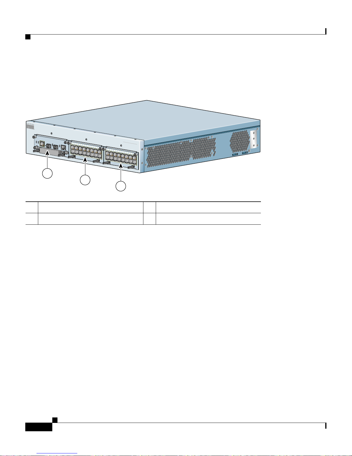
Figure 1-6 illustrates a fully-configured CSS 11503 and its slot locations.
Figure 1-6 Fully-Configured CSS 11503
MANAGEMENT
10BASE-T
LINK/ACT
DUPLEX
STATUS
GE 1
LINK
PCMCIA
SLOT 1
CSS5-SCM-2GE
1
2
3
SLOT 0
1
2
3
GE 2
LINK
4
5
6
7
8
9
10
11
1
2
13
14
15
CSS5-10M-16FE
16 Fast Ethernet
1
CONS
OLE
System Control
CSS5-10M-16FE
LINK
DPLX
LINK
DPLX
CISCO 11500
C
SERIES
O
N
T
E
N
T
S
E
R
V
I
C
E
S
S
W
I
T
C
2
3
4
5
6
7
LINK
LINK
H
8
9
10
11
1
2
13
14
15
DPLX
DPLX
16 Fast Ethernet
1
2
3
Chapter 1 Unpacking and Installing the CSS
59549
1 Slot location 1 3 Slot location 3
2 Slot location 2
Cisco 11500 Series Content Services Switch Hardware Installation Guide
1-22
78-13884-03
Page 51

Chapter 1 Unpacking and Installing the CSS
Figure 1-7 illustrates a fully-configured CSS 11506 and its slot locations.
Figure 1-7 Fully-Configured CSS 11506
1
CSS506-SM
MANAGEMENT
10BASE-T
LINK/ACT
DUPLEX
STATUS
GE 1
LINK
GE 2
LINK
SLOT 1
SLOT 0
C
ONSOLE
GE 1
LINK
GE 2
LINK
1
0
0
-
2
4
5
A
5
0
-
6
C
A
U
T
IO
N
DISCONNECT ALL
POWER SOURCES
BEFORE SERVICING
7
8
1
2
4
5
PS1
PS2
3
6
PS3
PCMCIA
CSS5-SCM-2GE
STATUS
CSS5-10M-2GE
A
C
D
C
O
K
O
K
4
0
V
0
~
H
z
1
System Control
CSS5-10M-16FE
1
CSS5-10M-16FE
Gigabit Ethernet
A
C
O
K
Installing a CSS Module
2
3
CSS506-SM
CISCO 11500
C
SERIES
O
N
T
E
N
T
S
E
R
V
I
2
3
4
5
6
7
8
9
10
1
1
12
13
1
4
15
1
2
3
4
LINK
DPLX
LINK
DPLX
2
3
4
5
6
7
8
9
LINK
DPLX
LINK
DPLX
D
C
O
K
CSS5-10M-16FE
16 Fast Ethernet
10
1
1
12
1
3
14
15
1
2
3
4
CSS5-10M-16FE
16 Fast Ethernet
A
C
D
C
O
K
O
K
1
0
0
-
2
4
0
V
~
5
A
5
0
-
6
0
H
z
C
E
S
S
W
I
T
C
H
5
6
7
8
9
1
0
11
12
13
14
15
LINK
DPLX
LINK
DPLX
5
6
7
8
LINK
LINK
16 Fast Ethernet
9
10
11
1
2
1
3
1
4
15
DPLX
DPLX
16 Fast Ethernet
59550
1
0
0
-
2
4
0
V
~
5
A
5
0
-
6
0
H
z
5
6
78-13884-03
1 Slot location 1 4 Slot location 4
2 Slot location 2 5 Slot location 5
3 Slot location 3 6 Slot location 6
Cisco 11500 Series Content Services Switch Hardware Installation Guide
1-23
Page 52

Installing a CSS Module
Unpacking a CSS Mo dule
To unpac k a CSS module:
1. Verify that th e modul e is the mo del you orde red by chec king the model
number listed on the side of the shi pping ca rton.
2. Remove the module from the shipping carton, leaving it in its anti-static bag.
3. Put on the anti-static strap provided with your CSS. Fo r example, wear the
anti-static wrist strap (inc luded in the accessory kit) and stick the copper -tape
end of the strap to an unpainted metal surface on the chassis. Make sure that
the wrist strap makes good contact with your skin.
4. Remove the module from the anti-static shielding bag and inspect it for
damage.
Always hold the module by the faceplate, being careful not to touch the
components. If the module appears to be damaged, return it to the anti-static
bag, repack it in the shi pping c arton, a nd conta c t you r loca l su ppli er.
Chapter 1 Unpacking and Installing the CSS
5. To install a module into the CSS chassis, see “Installing a Module”.
Installing a Module
Caution You must power down the CSS before installing or removing a module in a
CSS 11506.
Cisco 11500 Series Content Services Switch Hardware Installation Guide
1-24
78-13884-03
Page 53

Chapter 1 Unpacking and Installing the CSS
CISCO
11500
S
E
R
IE
S
CONTENT SERVICES SWITCH
15
14
13
1
2
11
10
D
P
L
X
1
6
F
a
s
t E
th
e
rn
e
t
D
P
L
X
To install a module:
1. Properly ground yourself prior to handling the module. For example, wear the
anti-static wrist strap (inc luded in the accessory kit) and stick the copper -tape
end of the strap to an unpainted metal surface on the chassis. Make sure that
the wrist strap makes good contact with your skin.
2. If necessary, power down the CSS.
3. Locate an ope n slo t in th e chas sis fo r the mo dule. S ee Table 1-3 to identify
possible slots for the m odule. If n ecessary, use a #1 Phillips screwdriver to
remove a blank panel from the chassi s to expose a slot for the mo dule.
4. Insert the module into the board guides at the left and right of the slot. Make
sure that the ejectors are fully extended outward. Slide the module into the
chassis by pressing firm ly a t th e l eft an d r ight of t he fac e plate as s hown in
Figure 1-8.
Installing a CSS Module
Figure 1-8 Installing a Module into a CSS Chassis
1
1
2
3
4
5
6
7
8
9
1
0
1
1
1
2
1
3
1
4
1
5
E
F
6
-1
M
0
-1
5
S
S
2
C
L
IN
K
D
P
L
X
L
IN
K
D
P
L
X
1 Spring-loa ded screw (one on
each side)
Close both ejectors simultaneously to seat the module connector into the
5.
t
e
rn
e
th
t E
s
a
F
6
1
2 Ejector (one on each side), extend
outward during inser tion
backplane.
59542
6. Using a Phillips screwdriver, tighten the spring-l oaded scre ws on the fr ont of
the module fa cepl at e.
7. Reboot the chassis to activate the module.
78-13884-03
Cisco 11500 Series Content Services Switch Hardware Installation Guide
1-25
Page 54

Installing a CSS Module
Installing a Passive SCM in a CSS 11506
You can inst all a passive SCM in a CSS 1 1506 c hassi s. A passive module is a
stand-by module in cas e of an a c tive module fail ure. A s im pl emen t ed in
WebNS 5.10 and greater, if the active SCM fails:
1. The CSS reboots and conne ction s are termi nated.
2. The CSS restores all configurations using the startup-config file.
3. The passive SCM becomes active automatically.
Note Passive modules do not load share pr ocessing functions w ith the active module.
To install a passive SCM:
1. Properly ground yo urse lf prio r to ha nd ling t he mod ule.
Chapter 1 Unpacking and Installing the CSS
2. As defined in Table 1-3, SCMs are re stricte d to slots 1 or 2.
3. If necessary, power down the CSS.
4. If necessary, remove a blank panel from the chassis to expose the slot.
5. Insert the module into the board guides at the left and right of the slot and
slide it into the chassis by pressin g firmly at the left and right of the fa ceplate.
6. Extend both ejectors simultaneously to seat the module connector into the
backplane.
7. Using a Phillips screwdriver, tighten the spring-l oaded scre ws on the fr ont of
the module fa cepl at e.
Cisco 11500 Series Content Services Switch Hardware Installation Guide
1-26
78-13884-03
Page 55

Chapter 1 Unpacking and Installing the CSS
8. Optionally, you can install the PCMCIA cover to the front of the disk slots
and secure it with its two spring -loa ded sc rews, as shown in Figure 1-9. Th e
cover protects the disks in the SCM.
Figure 1-9 Installing a PCMCIA Cover on an SCM
9. Reboot the CSS to initialize the passive SC M.
Installing a CSS Module
MANAGEMENT
10BASE-T
L
IN
K
/A
C
T
D
S
U
T
A
P
T
L
U
E
S
X
G
E
L
1
IN
K
G
L
E
IN
2
E
G
-2
M
C
-S
P
C
M
C
IA
5
S
S
L
O
T
S
C
1
S
L
O
T
0
K
l
CO
N
SO
tro
LE
n
o
C
m
te
s
y
S
59602
10. To copy the boot configuration from the active SCM to the passive SCM, use
the passive sync command in boo t c onfigura tio n m ode. For mo re
information, refer to the Content Services Switch Administration Guide.
78-13884-03
Cisco 11500 Series Content Services Switch Hardware Installation Guide
1-27
Page 56

Installing a CSS Module
Chapter 1 Unpacking and Installing the CSS
Cisco 11500 Series Content Services Switch Hardware Installation Guide
1-28
78-13884-03
Page 57

CHAPTER
2
Cabling the CSS
This chapter describes the indi vidual CSS interfa ces, how to cable th e CSS and its
interfaces, how to attach a c onsol e f or con sol e mana geme nt, a nd how to conn ec t
the AC power cord or the D C power cor d ( CSS 1 1503 a nd CSS 115 06 only ).
This chapter also describ es the CSS LED s and connecto rs. The information i n this
chapter appli es to t he CSS 115 01, CSS 11 503, a nd CSS 115 06, excep t whe re
noted.
This chapter contains the following sections:
• Cabling the CSS 11501
• Cabling the CSS 115 03 an d CSS 11 506 Mod ules
78-13884-03
• Connecting the Console
• Connecting the Chassis to Ground
• Connecting the Power Cord
Cisco 11500 Series Content Services Switch Hardware Installation Guide
2-1
Page 58

Cabling the CSS 11501
Cabling the CSS 11501
A CSS 11501 is a f ull y in tegrate d p lat fo rm, de livering transp ort an d a pp lica tio n
(layers 4-7) service s for Inter net and In tranet data cente rs. The CSS 115 01 is a
single-rack-uni t, with 6-G bps aggregate throughpu t. The in tegrated com pone nts
in the CSS 11501 contribute to the overall processing and memory needs for flow
set up and flow forwarding.
The fully integrated CSS 11501 is responsible for the following functi ons:
• System powerup and boot control
• Centralized rou ting t abl e m anage men t
• System-wide connection management
• An interface to an external Network Management Station
• Disk management
Chapter2 Cabling the CSS
• An external RS-232 interface
The CSS 11501 configuration supp orts:
• 288 MB RAM memory (2 56 MB of usab le memo ry)
• T wo PCMCIA slots for a hard or flash disk drive for the system software, and
logging and off-line system files. A cover is preinstalled over the slots.
• RJ-45 RS-232 Console port
• RJ-45 10-Mbps half-du plex Ether net manage ment co nnector
• RJ-45 RS-232 Diag connector (reserved for field service diagnostic use only).
• Eight auto-sensing 10/100-Mbps Ethernet (10B ASE- T/100B ASE-TX) interfaces
Cisco 11500 Series Content Services Switch Hardware Installation Guide
2-2
78-13884-03
Page 59

Chapter 2 Cabling the CSS
Cabling the CSS 11501
• SFP GBIC (1000BASE-SX or LX) with LC-type connectors. The GBIC can
use either:
–
Longwave-length SFP GBICs (CSS5-GBIC-LX). The longwave length
transceiver (1000BASE-LX) can reac h 550 mete rs for all multim ode
media types. For si ng le- mode fiber, the dist an ce i s 5,000 m ete rs.
–
Shortwave-length SFP GBICs (CSS5-GBIC-SX). The transceiver
distance can reac h from 220 m eters to 500 me ters, de pendin g on the
quality of the fiber.
Warning
Because invisible radiation may be emitted from the aperture of the port when
no fiber cable is connected, avoid exposure to radiation and do not stare into
open apertures.
The CSS 11501 fro nt p anel L EDs indi cate cha ssis an d con figuration status:
• Two stat us module LEDs indica ting power and device rea diness
• Link/Act and Duplex LEDs for the Ethernet Management port
• Link/Act and Duplex LEDs for each Ethernet port
• Link/Act LED for the SFP GBIC
78-13884-03
Cisco 11500 Series Content Services Switch Hardware Installation Guide
2-3
Page 60

Cabling the CSS 11501
CSS 11501 Connectors and LEDs
The CSS 11501 has all connectors and LEDs on the chassis front panel. Figure 2-1
illustrates the connec tors and LE Ds on the CSS 11501 .
For information on th e connector pinouts, refer to A ppendix B, Cable Connector
Pinouts.
Figure 2-1 CSS 11501 Connectors and LEDs
Chapter2 Cabling the CSS
6
7
8
L
I
N
K
D
P
L
X
L
I
N
K
D
P
L
X
L
I
N
K
D
P
L
X
L
IN
K
D
P
L
X
L
IN
K
D
P
L
X
L
I
N
K
D
P
L
X
L
I
N
K
D
P
L
X
L
IN
K
D
P
L
X
C
I
S
C
O
1
1
5
0
0
CONTENT SERVICES SWITCH
1
2
3
4
10/100
5
6
7
8
10/100
SERIES
G
E
L
I
N
K
6 RJ-45 Ethernet 10BASE-T/100BASE-TX connectors
1 through 8
1
1 B icolor status LED
(green and red)
1
10
2
4
3
S
T
A
T
U
S
C
O
N
S
O
L
E
11
5b
L
I
N
K
/
A
C
T
D
U
P
L
E
X
P
C
M
C
I
A
5a
9
2 A mber stat us LED 7 LC-type SFP GBIC (optional)
3 R J-45 RS- 232 Co nsol e c onne ctor 8 Link LED for SFP GBIC
4 10-Mbps half-duplex Ethernet
management c onnec t or
9 RJ-45 RS- 232 D iag conn ec tor f or field ser vi ce
diagnostic use only. (A connector cover is provided.
Removing the cover voids the warranty.)
78930
5a PCMCIA slot 0 containing a flash or
hard disk
5b PCMCIA slot 1 (shown empty) for
optional installation of a second flash
or hard disk
1. The Ethernet Link/Act LED and Duplex LED are located at the top of eac h RJ-4 5 Etherne t con nector and are not v isible i n thi s
illustration.
Cisco 11500 Series Content Services Switch Hardware Installation Guide
2-4
10 PCMCIA s l o t cover
11 Recessed button (reserved fo r fie ld se rvi ce u se onl y)
78-13884-03
Page 61

Chapter 2 Cabling the CSS
Table 2-1 describes the CSS 11501 LEDs and the ir indications.
Table 2-1 CSS 11501 LED Descriptions
Cabling the CSS 11501
LED Name Color State Indicates
Status (left) Green Solid The CSS 11501 is ready.
Variable
Disk activity is occurring.
blink
Slow blink The CSS 11 501 faile d.
Red Solid The CSS 11501 failed the
power-up self test during the boot
process.
Slow blink The CSS 11 501 failed.
No color Off The CSS 11501 failed a nd ha s no
power.
Status (right) Amber Fast blink The C SS 11 501 is r un ning
power-up self test.
Slow blink The CSS 11 501 is o ffline and
active.
Link/Act
for the Ethernet
Management Po rt
Green Off There is no link.
On The link is established but there is
no activity.
Blinking The link is established with
transmit or receive activity.
Duplex
for Ethernet
Management Po rt
Link/Act
for Ethernet Port
Duplex
for Ethernet Port
78-13884-03
Green Off Port is operating at half duplex.
On Port is opera ting at fu ll duplex.
Green Off No link established.
On Link establ ished but no activity.
Blinking Link e stablished w ith transmi t or
receive activity.
Green Off Port is operating at half duplex.
On Port is opera ting at fu ll duplex.
Cisco 11500 Series Content Services Switch Hardware Installation Guide
2-5
Page 62

Cabling the CSS 11501
Chapter2 Cabling the CSS
Table 2-1 CSS 11501 LED Descriptions (continued)
LED Name Color State Indicates
Link /Act
for the Gigabit
Ethernet P ort
Green Off There is no link.
On The link exists and
synchronizati on is achieved.
Blinking The link is established with
transmit or receive activity.
Cisco 11500 Series Content Services Switch Hardware Installation Guide
2-6
78-13884-03
Page 63

Chapter 2 Cabling the CSS
Cabling the CSS 11503 and CSS 11506 Modules
Cabling the CSS 11503 and CSS 11506 Modules
The CSS 11503 and CSS 11506 modules have connectors and LEDs on their front
panels. The following section s describe :
• CSS 11503 and CSS 11506 Module Overview
• Switch Control Module Connectors and LEDs
• Fast Ethernet Module Connectors an d LEDs
• Gigabit Etherne t M odul e Co nne cto rs an d LED s
• Session Accele rato r Mo dul e L EDs
• Secure Socket Layer (SSL) Module LEDs
For information on th e connector pinouts, refer to A ppendix B, Cable Connector
Pinouts.
CSS 11503 and CSS 11506 Module Overview
The CSS 11503 and CSS 11506 are compa ct modular plat form s, delivering
transport and application (layers 4-7) services for Internet and Intranet data
centers. A CSS is a fully-distributed architecture with all modules in the system
contributing to the overall processi ng and memo ry need s for flow set up.
Performance increases incrementally as you add modules, and the modules
balance the overall traffic load.
• The Cisco 1150 6 is a five-rack unit, suppo rt ing six-slot s, w ith 40- Gbps
aggregate throu ghput . The CSS 1 1506 r eq uire s at le as t one Switc h Cont r ol
Module (SCM) and ma y be co nfigur ed wit h a sec on d SCM i n stan dby mode
for redundancy. With the required SCM in one slot , the CSS 11506 ha s five
additional slots support ing any combin ation of I/O module s.
• The Cisco 11503 is a two-rack- unit, supporting th ree-sl ots, with 20-G bps
aggregate throu ghput . The CSS 1 1503 r eq uire s an SCM and a ccom mod ate s
any two of the other m odul es.
Though all modules participate in flow setup, they differ primarily in control
functions, pe rf orm ance , a nd I/O. Ea ch C SS 11 500 m odule con si sts of o ne
high-speed MIPS RISC processor for flow-setup, one network processor for flow
forwarding, one poli cy co-proce ssor for searc h operat ions and a ma ximum of
288 MB of RDRAM (up to 256 MB of usable me mory) .
78-13884-03
Cisco 11500 Series Content Services Switch Hardware Installation Guide
2-7
Page 64

Cabling the CSS 11503 and CSS 11506 Modules
The CSS 11506 not only supports re dunda ncy in SCMs but also supports
redundant power supplie s and re dunda nt Sw itch Mod ules (2 0 Gb ps ea ch).
The CSS modules are as follows:
• 144 MB or 288 MB (128 MB or 256 MB of usab le memor y) Switch Contro l
Module (SCM) with:
–
Two 1000 -M bps E therne t (1 000 BASE-SX or LX ) sma ll- form facto r
pluggable gigabit interface converters (SFP GBICs) with LC-type
connectors.
–
T wo PCMCIA slots for a hard or flash disk drive for the system software,
and logging a nd off-line system files.
–
RJ-45 RS-232 Console port
–
1 RJ-45 10-Mbps half-du plex Etherne t manageme nt conne ctor.
• Switch Module (SM) . An SM provides conn ectivity amo ng the SCM and
IOMs.
Chapter2 Cabling the CSS
–
The CSS 11503 has a single integrated SM. A single SM has an aggregate
throughput of 20 Gbps.
–
The CSS 11506 has two removable SMs that share the switc hing
functions. Two SMs provide 40 Gbps a ggregate t hro ughput . As
implemented in WebNS 5.10 and greater, if one SM fails, the CSS
reboots and continues to ope rate throu gh the other SM.
• Two slots in the CSS 11503 and five slots in the CSS 11506 are configurable
with:
–
Fast Ethernet Module s that provid e eithe r 8 or 16 auto-se nsing
10/100-Mbps Et hern et (
–
Gigabit Ethernet Mod ule s pr ovides up to two 100 0-Mbp s E the rnet
10BASE-T/100BASE-TX) RJ-45 port s.
(1000BASE-SX or LX) SFP GBICs with LC-type connectors.
–
A Session Accelerator Module (SAM) that provides a cost-effective way
to add flow performance when additional connectivity is not required.
Using the same flow setup and forwarding processors as the I/O modules,
it provides the flexibility to optimize the CSS for port density and
performance.
Cisco 11500 Series Content Services Switch Hardware Installation Guide
2-8
78-13884-03
Page 65

Chapter 2 Cabling the CSS
Figure 2-2 illustrates a fully-configured CSS 11503 and its components.
Figure 2-2 CSS 11503 Content Services Switch
Cabling the CSS 11503 and CSS 11506 Modules
–
A Secure Sock et La ye r (SSL) module th at fu n ction s as an SSL server by
adding securit y service s between the Web browsers (the client) and
HTTP servers. The SSL module is responsible for all user authentication,
public/private key generation, certificate management, and packet
encryption a nd dec ryp tio n f unct ions bet wee n th e cli ent an d t he serv er.
Each SSL module terminates SSL connections received from a client.
The CSS 11503 supports a maximum of two SSL modules and the CSS
11506 supports a maximum of four SSL modu les. For information on SSL
commands and f unct ions, r efer to the Ci sco Content Se rvices Swit ch
Advanced Co nfiguration G uid e.
–
An additional SCM to serve as a passive redundant module.
M
A
N
A
G
E
M
E
N
T
1
0
B
A
S
E
-
T
L
IN
K
/
A
C
T
D
S
U
T
A
P
T
L
U
E
S
X
G
E
L
1
IN
K
E
G
-2
M
C
-S
P
C
M
C
IA
5
S
S
L
O
T
1
S
C
1
2
3
S
L
O
T
0
1
2
3
G
E
2
4
L
IN
K
5
6
7
8
9
1
0
1
1
1
2
1
3
1
4
1
l
E
o
C
O
F
N
SO
tr
L
E
6
n
-1
o
M
C
0
m
-1
5
te
s
S
y
S
S
C
5
t
e
E
n
L
IN
K
L
IN
K
F
r
6
D
e
P
L
X
-1
h
t
M
0
D
P
L
t E
X
-1
s
5
a
S
F
S
6
C
1
C
IS
C
O
1
1
5
0
0
C
S
O
E
R
N
I
E
T
S
E
N
T
S
E
R
V
IC
E
S
SW
IT
C
1
2
3
4
5
6
H
7
8
9
1
0
1
1
1
2
1
3
1
4
1
5
t
e
L
IN
K
rn
D
e
P
L
X
th
L
IN
K
E
D
P
L
t
X
s
a
F
6
1
1
2
3
1 Slot 1 for the SCM only 3 Slot 3 for an I/O module
2 Slot 2 for an I/O modu le
59549
78-13884-03
Cisco 11500 Series Content Services Switch Hardware Installation Guide
2-9
Page 66

Cabling the CSS 11503 and CSS 11506 Modules
Figure 2-3 illustrates a fully-configured CSS 11506 and its components.
Figure 2-3 CSS 11506 Content Services Switch
Chapter2 Cabling the CSS
2 4 5
CSS506-SM
MANAGEMENT
10BASE-T
LINK/ACT
DUPLEX
STATUS
GE 1
LINK
PCMCIA
C
A
U
T
IO
N
DISCONNECT ALL
POWER SOURCES
BEFORE SERVICING
7
8
1
2
4
5
PS1
PS2
3
6
PS3
CSS5-SCM-2GE
STATUS
CSS5-10M-2GE
A
C
O
K
1
GE 2
SLOT 1
SLOT 0
GE 1
LINK
GE 2
D
C
O
K
3
CSS506-SM
CISCO 11500
C
SERIES
O
N
T
E
N
T
S
E
1
2
3
LINK
LINK
4
5
6
7
8
9
10
1
1
12
1
3
14
15
1
2
CON
SO
LE
System Control
CSS5-10M-16FE
LINK
DPLX
LINK
DPLX
1
2
3
4
5
6
7
8
9
1
0
11
12
CSS5-10M-16FE
Gigabit Ethernet
LINK
DPLX
LINK
DPLX
A
C
D
C
O
K
O
K
1
0
0
-
2
4
0
V
~
5
A
5
0
-
6
0
H
z
3
CSS5-10M-16FE
16 Fast Ethernet
13
14
15
1
2
3
CSS5-10M-16FE
16 Fast Ethernet
A
C
D
C
O
K
O
K
1
0
0
-
2
4
0
V
~
5
A
5
0
-
6
0
H
z
R
V
I
C
E
S
S
W
I
T
C
H
4
5
6
7
8
9
1
0
11
12
1
3
14
15
LINK
DPLX
LINK
DPLX
4
5
6
7
8
LINK
LINK
16 Fast Ethernet
9
10
11
12
1
3
1
4
1
5
DPLX
DPLX
16 Fast Ethernet
59527
1
0
0
-
2
4
0
V
~
5
A
5
0
-
6
0
H
z
6
2-10
1 Fan mo du le 4 Slot 2 for an SCM or I/O module
2 Slot 1 for the SCM 5 Slot 6
3 Switch Modules in slots 7 and 8 6 Power supplies 1, 2, and 3
1. Slots 3 through 6 are for I/O modules, including SAMs and SSL modules.
Cisco 11500 Series Content Services Switch Hardware Installation Guide
1
78-13884-03
Page 67

Chapter 2 Cabling the CSS
Cabling the CSS 11503 and CSS 11506 Modules
Switch Control Module Connectors and LEDs
The Switch Control Module (SCM), model CSS5-SCM-2GE, provides master
control and is re sponsi ble fo r t he f ollowing f unct ions:
• System powerup and boot control
• Centralized rou ting t abl e m anage men t
• System-wide connection management
• An interface to an external Network Management Station
• Disk management
• An external RS-232 interface
A CSS supports a maximum of two SCMs, one ac tive and one passive.
The Switch Control Mod ule contai ns the following conn ectors and sl ots:
• 1 RJ-45 10-Mbps half-du plex Etherne t manageme nt conne ctor.
• 1 RJ-45 RS-23 2 C onso le co nne cto r.
• 1 RJ-45 RS-23 2 Di ag c on nector ( res erved f or field se rvic e dia gnost ic u se
only).
• 2 SFP GBICs (1000BASE-SX or LX) with LC-type connectors.
• Two PCMCIA slots for a hard disk or flash disk. A cover is preinstalled over
the slots.
Note The SCM can have a maximum of two disk drives.
The SCM front pane l L EDs in dicat e m odu le and c on figuration status:
• Two stat us module LEDs indica ting power and mod ule rea diness
• Link/Act and Dup lex LEDs for th e Ether net mana gement port
• Link LEDs for each SFP GBIC
Warning
Because invisible radiation may be emitted from the aperture of the port when
no fiber cable is connected, avoid exposure to radiation and do not stare into
open apertures.
78-13884-03
Cisco 11500 Series Content Services Switch Hardware Installation Guide
2-11
Page 68

Cabling the CSS 11503 and CSS 11506 Modules
Figure 2-4 illustrates the SCM front panel connectors, PCMCIA slots, an d LEDs.
Figure 2-4 Switch Control Module Connectors and LEDs
Chapter2 Cabling the CSS
6
345
MANAGEMENT
10BASE-T
L
IN
K
/A
C
T
D
S
U
T
A
P
T
L
U
E
E
-2G
M
C
5-S
S
S
C
S
P
C
M
C
IA
S
L
O
T
1
S
L
O
T
0
2
1
7
11b
X
G
E
L
1
IN
K
G
L
E
IN
2
K
9
8
C
O
N
S
O
trol
L
E
on
C
ystem
S
78993
10 11a12
1 10-Mbp s half-dup lex Ethernet ma nageme nt
8 RJ-45 RS-2 32 Consol e connec tor
connector
2 Bicolor sta tus L ED (g reen a nd red) 9 RJ-4 5 RS-232 Dia g conne ctor for field
service diagnostic use only. (A connector
cover is provided. Removing the cover voids
the warranty.)
3 Amber st at us LED 10 PCM CIA s lo t c over
4 Link/A ct LED 11a PCMCIA slot 0 containing a fl ash or hard
5 Duplex LED 11b PCMCIA slot 1 (shown empty) for optiona l
6 LC-type SFP GBIC (one of two) 12 Recessed button (reser ved for field service
7 Link LED for the associated SFP GBIC on
the left
Cisco 11500 Series Content Services Switch Hardware Installation Guide
2-12
disk
installation of a seco nd flash or ha rd disk
use only)
78-13884-03
Page 69
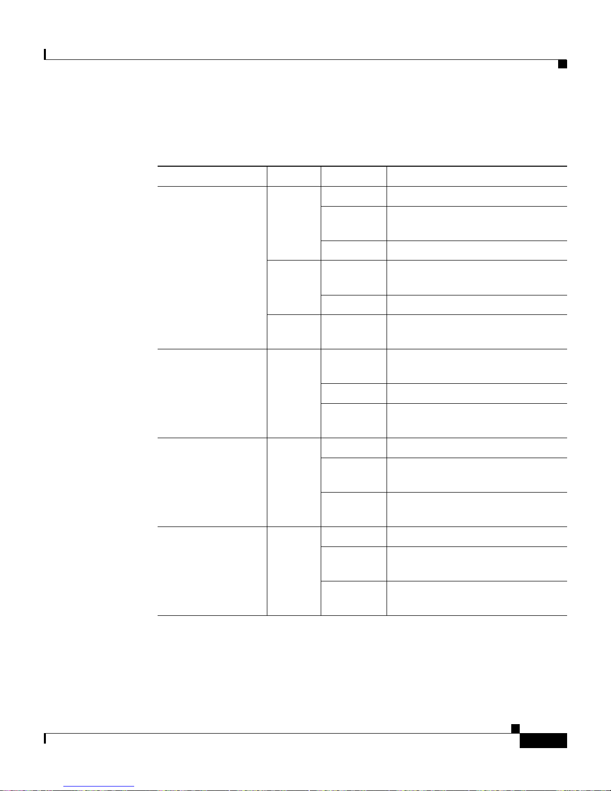
Chapter 2 Cabling the CSS
Table 2-2 describes the SCM LEDs an d their indi cation s.
Table 2-2 Switch Control Module LED Descriptions
Cabling the CSS 11503 and CSS 11506 Modules
LED Name Color State Indicates
Status (left) Green Solid The module is ready.
Variable
Disk activity is occurring.
blink
Slow blink Another CSS module failed.
Red Solid The module failed the power-up
self test during the boot process.
Slow blink The module failed.
No color Off The module failed and has no
power.
Status (right) Amber Fast blink The m odul e i s runni n g power-up
self test.
Slow blink The module is offline and active.
Solid The modu le is online an d not
active (passive SCM).
Link/Act
for the Ethernet
Management Po rt
Green Off There is no link.
On The link is established but there is
no activity.
Blinking The link is established with
transmit or receive activity.
Link
for each Gigabit
Ethernet P ort
78-13884-03
Green Off There is no link.
On The link exists and
synchronizati on is achieved.
Blinking The link is established with
transmit or receive activity.
Cisco 11500 Series Content Services Switch Hardware Installation Guide
2-13
Page 70

Cabling the CSS 11503 and CSS 11506 Modules
Fast Ethernet Module Connectors and LEDs
The FEM is available in two models:
• Model CSS5-IOM-8 FE co ntai ns 8 au to-se nsin g R J-45 Fast Et h erne t
10/100-Mbps 10BASE-T/100BASE-TX con ne ctor s.
• Model CSS5-IOM-16FE cont ains 16 auto -sensing RJ-45 Fast Ethe rnet
10/100-Mbps 10BASE-T/100BASE-TX con ne ctor s.
Each connector has Link and Duplex LEDs. The LEDs indicate the module and
network status. Figure 2-5 illustrates the LEDs and connectors on the 8-port FEM.
Figure 2-5 8-Port Fast Ethernet Module Connectors and LEDs
2
Chapter2 Cabling the CSS
3
1
2
3
4 5
4
5
6
7
8
1
CSS5-10M-8FE
LINK
DPLX
LINK
DPLX
3
2
1 RJ-45 E the rnet
10BASE-T/100BASE-TX
connector 1 (connector 2 is
shown directly above it)
8 Fast Ethernet
6
4 RJ-45 Etherne t
10BASE-T/100BASE-TX connector
8 (connector 7 is shown dir ectly
below it)
59534
2 Link LED (on e ach co nnecto r) 5 Spring-loade d screw (one of two)
3 Duplex LED (on ea ch
6 Ejector (one of two)
connector)
Figure 2-6 illustrates the LEDs and connectors on the 16-port FEM.
Cisco 11500 Series Content Services Switch Hardware Installation Guide
2-14
78-13884-03
Page 71

Chapter 2 Cabling the CSS
Figure 2-6 16-Port Fast Ethernet Module Connectors and LEDs
Cabling the CSS 11503 and CSS 11506 Modules
2
3
1
2
3
4
5
6
7
8
9
10
11
4
12
13
14
15
5
1
CSS5-10M-16FE
CSS5-10M-16FE
1 RJ-45 E the rnet
10BASE-T/100BASE-TX
connector 1 (connector 2 is
shown directly above it)
LINK
LINK
DPLX
DPLX
LINK
LINK
DPLX
DPLX
16 Fast Ethernet
3
2
6
16 Fast Ethernet
59533
4 RJ-45 Ethernet
10BASE-T/100BASE-TX connect or
16 (connector 15 is sh own dire ctl y
below it)
2 Link LED (on e ach co nnecto r) 5 Spring-loaded sc rew (one o f two)
3 Duplex LED (on ea ch
6 Ejecto r (o ne of two)
connector)
78-13884-03
Cisco 11500 Series Content Services Switch Hardware Installation Guide
2-15
Page 72

Cabling the CSS 11503 and CSS 11506 Modules
Table 2-3 describes the FEM LEDs and their indi cations.
Table 2-3 Fast Ethernet Module LED Descriptions
LED Name Color State Indicates
Link Green Off No link establi shed
Duplex Green Off Port is opera ting at ha lf duplex
Chapter2 Cabling the CSS
On Link established but no activity
Blinking Link established with transmit or receive
activity
On Port is operating at ful l duplex
Note If a ll of t he FE M L ink an d D upl ex LED s b link sy nc hro nously, the module ha s
failed.
Gigabit Ethernet Module Connectors and LEDs
The Gigabit Etherne t Modul e (GEM) , model CSS5- IOM-2GE , cont ains two
1000-Mbps SFP GBICs with LC-type connectors. The GEM can use either:
• Longwave-length SFP GBICs (CSS5-GBIC-LX). The longwave length
transceiver (1000BASE-LX) can reac h 550 mete rs for all multimod e media
types. For single-m ode fiber, the distanc e is 5 ,000 me ter s.
• Shortwave-length SFP GBICs (CSS5-GBIC-SX). The transceiver distance
can reach from 220 meters to 500 meters, depending on the quality of the
fiber.
Warning
Because invisible radiation may be emitted from the aperture of the port when
no fiber cable is connected, avoid exposure to radiation and do not stare into
open apertures.
Cisco 11500 Series Content Services Switch Hardware Installation Guide
2-16
78-13884-03
Page 73

Chapter 2 Cabling the CSS
The GEM front panel LEDs indicate the network status for each of the connectors
(Link LEDs). Figure 2-7 illust rates the LE Ds and co nnectors on a G EM.
Figure 2-7 Gigabit Ethernet Module Connectors and LEDs
Cabling the CSS 11503 and CSS 11506 Modules
3
2
S
T
A
T
U
1
S
E
G
-2
M
0
-1
5
S
S
C
G
E
1
4
4
L
IN
K
G
E
2
5
L
IN
K
t
e
n
r
e
th
it E
b
a
ig
G
2
59535
6
1 Bicolor status LED (green and
red)
4 Link LED (next to its
corresponding SFP GBIC)
2 Amber status LED 5 Spring-loaded screw (one of two)
3 LC-typ e SFP GBIC (one of two) 6 Ejector (one of two)
Table 2-4 describes the GEM LEDs.
78-13884-03
Table 2-4 Gigabit Ethernet Module LED Desc riptions
LED Name Color State Indicates
Status (left) Green Solid The module is ready.
Red Solid The module failed the power-up self
test during the boo t pr ocess.
Slow blink The module failed.
No color Off The module failed and has no power.
Status (right) Amber Fast blink The module is runn ing power-up self
test.
Slow blink The module is offline and active.
Solid The module is online and not active.
Cisco 11500 Series Content Services Switch Hardware Installation Guide
2-17
Page 74

Cabling the CSS 11503 and CSS 11506 Modules
Table 2-4 Gigabit Ethernet Module LED Descriptions (continued)
LED Name Color State Indicates
Link Green Off There is no link.
On The link exists and synchronization is
Blinking The link is established with transmit
Session Accelerator Module LEDs
The Session Accelerator Module (SAM), model CSS5-SAM, is used with the
SCM to provide additional processing support for session setup. The SAM front
panel LEDs indicate its operational status. The SAM has no connectors.
Chapter2 Cabling the CSS
achieved.
or receive activity.
Figure 2-8 illustrates the SAM front panel LEDs.
Figure 2-8 Session Accelerator Module LEDs
2
3
STATUS
STATUS
1
CSS5-SAM
CSS5-SAM
4
Session Accelerator
Session Accelerator
59537
1 Bicolor status LED (green and red) 3 Spring -loaded scr ew (one of two)
2 Amber status LED 4 Ejector (one of two)
Cisco 11500 Series Content Services Switch Hardware Installation Guide
2-18
78-13884-03
Page 75

Chapter 2 Cabling the CSS
Table 2-5 describes the LEDs.
Table 2-5 Session Accelerator Module LED Descriptions
Cabling the CSS 11503 and CSS 11506 Modules
LED Name Color State Indicates
Status
(left)
Green Solid The module is ready.
Red Solid The module failed the power-up self test
during the boot proce ss.
Slow blink The module failed.
No color Off The module fa iled an d has no power.
Status
(right)
Amber Fast blink The module is running power-up self test.
Slow blink The module is offline and active.
Solid The module is online and n ot a ctive.
Secure Socket L a yer (S SL ) Modu le LE Ds
The Secure Socket Layer (SSL) module, model CSS5-SSL-K9, operates as an
SSL server by adding security service s between Web browsers (the client) and
HTTP servers. The SSL module is responsible for all user authentication,
public/p ri va te k ey gene ratio n, ce rtif ic ate mana geme nt, a nd pac ket encryp tion and
decryption func tio ns be twe en t he cli ent and the server. Each SSL mod ule
terminates SSL connections received from a client.
The front panel LE Ds on the mod ule indic ate its ope rationa l status. Th e SSL
module has no connectors.
The CSS 11503 supports a maximum of two SSL modules and the CSS 11506
supports a maximum of four SSL modules.
78-13884-03
Cisco 11500 Series Content Services Switch Hardware Installation Guide
2-19
Page 76

Cabling the CSS 11503 and CSS 11506 Modules
Figure 2-9 illustrates the SSL module front panel LEDs.
Figure 2-9 SSL Module LEDs
2
STATUS
STATUS
1
CSS5-SAM
CSS5-SAM
1 Bicolor status LED (green and red) 3 Spring -loaded scr ew (one of two)
4
3
Session Accelerator
Session Accelerator
Chapter2 Cabling the CSS
59537
2 Amber status LED 4 Ejector (one of two)
Table 2-6 describes the LEDs.
Table 2-6 SSL Module LED Descriptions
LED Name Color State Indicates
Status
(left)
Green Solid The module is ready.
Red Solid The module failed the power-up self test
during the boot proce ss.
Slow blink The module failed.
No color Off The module fa iled an d has no power.
Status
(right)
Amber Fast blink The module is running power-up self test.
Slow blink The module is offline and active.
Solid The module is online and n ot a ctive.
Cisco 11500 Series Content Services Switch Hardware Installation Guide
2-20
78-13884-03
Page 77

Chapter 2 Cabling the CSS
Connecting the Console
To connect a console to the CSS, attach the console cable (provided in the
accessory kit) to the Console port on the CSS. Your terminal settings must match
the CSS default settings specified in Table 2-7.
Table 2-7 CSS Console Port Default Settings
Parameters Default Settings
Baud 9600
Data Bits 8
Parity None
Stop Bits 1
Terminal Type VT100/ ANSI
Connecting the Console
Flow Control None
78-13884-03
Cisco 11500 Series Content Services Switch Hardware Installation Guide
2-21
Page 78

Connecting the Chass is to Ground
Connecting the Chassis to Ground
Connecting the CSS 1 1503 or CSS 115 06 chassi s to ear th gr oun d is r equire d for
all DC-po wered installations , and any A C-po wered installatio n where compliance
with Te lcordia (formerly Bellcore) grounding requirements is necessary. Ha ve the
recommended t o ols a nd suppl ies available bef ore y ou begin thi s pr oced ure (see
Table 2-8).
Chapter2 Cabling the CSS
Warning
Never defeat the ground conductor or operate the equipment in the absence of
a suitably installed ground conductor. Contact the appropriate electrical
inspection authority or an electrician if you are uncertain that suitable
grounding is available.
Tools and Supplies
The accessory kit shipped with the CSS contains the following items used in this
procedure:
• One 2-hole grou nding l ug (Pandui t no . LCD6- 10 A-L)
• Two M5 screws for the gr ounding l ug
Table 2-8 lists the other tools, equipment, and supplies that you need to connect
system ground to the cha ssis. These are ite ms that yo u must suppl y.
Table 2-8 Tools and Supplies
Quantity Description Comments
1 Number 2 Phillips screwdriver —
1 Wire stripping tool Choose a tool that does not nick
Varies Groun ding wire 6 AWG, 0.204 in . (5.18 mm)
Varies Screws to attach ground wire to
Cisco 11500 Series Content Services Switch Hardware Installation Guide
2-22
grounding po int a t si te
the wire.
recommended. The wire should
have applicable agency
approvals such as Telcordia.
Part requirements depend on
location.
78-13884-03
Page 79

Chapter 2 Cabling the CSS
Table 2-8 Tools and Supplies (continued)
Connecting the Chassis to Ground
Quantity Description Comments
1 or 2 2-hole gro und ing lu g. L ug mu st
fit 6 AW G stra nded c opp er or
37/24 flex cables. Each lug must
have two holes, centered
Recommended types:
• Panduit no. LCD6-10A-L
(1 supplied in accessory
kit)
0.625 in. (1.587 cm) apart, and
must accept M5 screws.
• Panduit no. LCC6-10A-L
(long barrel)
One lug is supplied by Cisco
Systems in the accessory kit. The
supplied lug is for the router end
of the ground wire. You may
• Thomas & Betts no.
256-30695-1183(* 4*)
• Burndy no. YA6CL2TC 10
wish to use a lug other than the
one supplied. If you nee d a lug
for the facility end of the g round
wire, you must supply it.
1 Crimping tool Mu st fit diameter of grou nding
lugs. Cisco Systems
recommends tha t y ou use a
crimping tool recommended by
the lug manufacture r.
78-13884-03
2 M5 screws with captive, locking
washers
Cisco 11500 Series Content Services Switch Hardware Installation Guide
Included in accessory kit
shipped with the CS S.
2-23
Page 80

Connecting the Chass is to Ground
Attaching the Grounding Cabl e
The following proced ure descr ibes how to attach:
• The grounding lug to the groundin g cable
• The grounding cabl e to the chassi s
Chapter2 Cabling the CSS
Warning
When you install or replace the unit, the ground connection must always be
made first and disconnected last.
1. Power off the chassis by settin g th e p ower switch (or switches) to the O (off)
position.
2. Strip the covering from the end of the grounding wire (Figure 2-10). The
amount of covering t o be st rip pe d varies depe nding on the type of l ug you
plan to attach to the wire.
Lug Strip Length
Panduit no. LCD6-10A- L
13/16 inch (2 cm)
(supplied in accessory kit)
Panduit no. LCC6-10A -L
1 1/16 inch (2.7 cm)
(long barre l)
Thomas & Betts no.
3/4 inch (1.9 cm)
256-30695-118 3(*4*)
Burndy no. YA6C L2TC1 0 7/8 inch (2.2 cm)
3. Insert the strippe d end of the gro unding wi re into th e open end of a l ug
(Figure 2-10) and crimp the grounding lug securely to the wire. Use the lug
manufacturer’s recommended crimping tool and crimping procedure to
ensure a proper cr imp.
Cisco 11500 Series Content Services Switch Hardware Installation Guide
2-24
78-13884-03
Page 81

Chapter 2 Cabling the CSS
Figure 2-10 Attaching Grounding Wire to Grounding Lug
Connecting the Chassis to Ground
53632
Grounding lugStripped wire
Attach the grounding lug firmly to the threaded holes on the chassis using two
4.
M5 screws.
• On the CSS 11503 chassis, the holes are located on the left side (looking
from the rear) near the bottom rear corner.
• On the CSS 11506 c hassi s, th e h oles ar e loca ted on the righ t re ar pane l.
The three thre ad ed h oles ar e u n evenly spaced to accom moda te d ifferent lugs.
5. Strip the covering from the other end of the grounding wire. See the table in
step 2 for strip l eng ths f or differen t lugs .
6. Insert the stripped end of the grounding wire into the open end of a grounding
lug and crimp the groun ding lug sec urely to the wire .
7. Attach the gro und ing l u g to an a pp rop ria te ground in g poi nt at your sit e.
8. Go to the next section, “Connecting the Power Cord”.
78-13884-03
Cisco 11500 Series Content Services Switch Hardware Installation Guide
2-25
Page 82

Connecting the Power Cord
Connecting the Power Cord
The CSS 11500 series mode ls ar e powered by eithe r an AC or DC power supply.
Before you install the AC or DC power cord, ensure that you have read
Appendix A, Specifications, for info rmati on on t he elec trical spe cif icat ions . Th e
following sections describe:
• Connecting a CSS 115 01 Power Cord
• Connecting a CSS 115 03 Power Cord
• Connecting a CSS 115 06 Power Cord
• Checking the DC Power Connectio n (CSS 1 150 3 and CSS 11 506)
Connecting a CSS 11501 Power Cord
Chapter2 Cabling the CSS
To connect an AC power cord to a CSS 11501:
1. At the rear of the chassis, ensure that the CSS power switch is in the O (off)
position.
2. Plug the AC power cord connector into the CSS power connector, as shown
in Figure 2-11.
Figure 2-11 Connecting a CSS 11501 AC Power Cord
1
78677
2
1 AC power connector 2 Power switch
Cisco 11500 Series Content Services Switch Hardware Installation Guide
2-26
78-13884-03
Page 83

Chapter 2 Cabling the CSS
100-240V
~
50-60 Hz
5A
430 W
3. Plug the power cord into a dedicat ed 3-wire groundin g recept acle.
4. To p ower on and boo t t he CSS, ref er to Cha pter 3, Booting and Configuring
the CSS.
Connecting a CSS 11503 Power Cord
The following sections provide information on:
• Connecting a CSS 115 03 AC Power Cord
• Connecting a CSS 115 03 DC Power Cor d
Connecting a CSS 11503 AC Power Cord
To connect an AC power cord to a CSS 11503:
Connecting the Power Cord
1. At the rear of the chassis, ensure that the CSS power switch is in the O (off)
position.
2. Plug the AC power cord connector into the CSS power connector, as shown
in Figure 2-12.
Figure 2-12 Connecting a CSS 11503 AC Power Cord
1
59543
1 Power switch 2 AC power connector
78-13884-03
2
Cisco 11500 Series Content Services Switch Hardware Installation Guide
2-27
Page 84

Connecting the Power Cord
3. Plug the power cord into a dedicat ed 3-wire groundin g recept acle.
4. To p ower on and boo t t he CSS, ref er to Cha pter 3, Booting and Configuring
the CSS.
Connecting a CSS 11503 DC Power Cord
Before you install a DC power co rd, refe r to Ap pe ndix A , Specifications, for the
DC power supply.
Chapter2 Cabling the CSS
Warning
Warning
Warning
Warning
Warning
The DC power supply cord requires at least a 14 AWG wire (maximum 10 AWG
wire). The CSS 11503 draws a maximum of 10 amps.
Use copper conductors only.
Before working on equipment that is connected to power lines, remove jewelry
(including rings, necklaces, and watches). Metal objects will heat up when
connected to power and ground and can cause serious burns or weld the metal
object to the terminals.
Before performing the DC installation procedure, ensure that power is removed
from the DC circuit. To ensure that all power is off, locate the circuit breaker
that services the DC circuit and switch it off.
When you are installing or replacing the unit, the ground connection must
always be made first and disconnected last .
Cisco 11500 Series Content Services Switch Hardware Installation Guide
2-28
78-13884-03
Page 85

Chapter 2 Cabling the CSS
Connecting the Power Cord
Warning
Only a DC power source that is isolated from AC mains with reinforced
insulation, and that complies wit h t he other s afety ext ra-low voltage ( SELV)
requirements in UL1950, CSA 950 3rd Edition, EN 60950, and IEC950, can be
connected to a Cisco 11503 system. This requirement ensures that in a
catastrophic power source fault condition, hazardous voltages are not present
on power terminals and connectors.
To con ne ct the CSS 115 03 DC power suppl y to a p ower sourc e:
1. At the rear of the chassis, ensure that the CSS power switch is in the O (off)
position.
2. Locate the DC terminal block on the rear of the chassis as shown in
Figure 2-13.
Figure 2-13 Location of the CSS 11503 DC Power Supply Connectors
78-13884-03
-48/-60V
9.0A,430VA
59544
1 2
1 Terminal block (–, +, and ) 2 Power switch
Cisco 11500 Series Content Services Switch Hardware Installation Guide
2-29
Page 86

Connecting the Power Cord
3. Using a flat-head screwdriver, loosen the captive screws on the three DC
Chapter2 Cabling the CSS
connectors (labeled from left to right, –, +, and , respectively).
Warning
Warning
Before installing a wire, ensure that the polarity of the DC connections is
correct. Reversed polarity causes damage to the DC power supply and can
create a dangerous shock hazard.
Do not consolidate the end of a conductor by soft soldering prior to installation.
4. Install the wires in to th e appro pria te co nnec tor. Make sure that th e
non-insulated p ar t of ea ch wire is 9 m m (0. 35 inc hes ) i n le ngth .
When installing the wires, always connect the ground wire first. When
disconnecting the wires, always dis connect the ground wire last.
5. Tighten the captive screws to 5 to 7 inch-pounds (0.6 to 0.8 Nm) of torque to
secure the wires in the connectors. Ensure that the wires are held firmly in
place.
6. Install the wires to the DC power source.
For the proper power cable wiring betw een the CSS 11503 a nd DC power
source, see Table 2-9.
2-30
Table 2-9 CSS 11503 to DC Power Source Cabling
CSS 11503 DC Power Source
(Ground)
(Ground)
++
––
Warning
The proper wiring sequence is ground to ground, positive to positive, and
negative to negative. The ground wire should always be connected first and
disconnected last.
Cisco 11500 Series Content Services Switch Hardware Installation Guide
78-13884-03
Page 87

Chapter 2 Cabling the CSS
7. Switch on the circuit breaker that services the DC circuit.
8. T o chec k the DC po wer conn ection, see “Checking the DC Power Connection
(CSS 11503 and CSS 11506)”.
Connecting a CSS 11506 Power Cord
The following sections provide information for connecting an AC or DC power
cords to a CSS 11506.
• Connecting a CSS 115 06 AC Power Cord
• Connecting a CSS 115 06 DC Power Cor d
Connecting a CSS 11506 AC Power Cord
Connecting the Power Cord
To con nect the AC power cord to each power supply in the CSS 115 06:
1. At the front of the supply, ensure that the CSS power switch is in the O (off)
position.
2. Plug the AC power cord conn ect or into t he power conn ec tor, as shown in
Figure 2-14.
78-13884-03
Cisco 11500 Series Content Services Switch Hardware Installation Guide
2-31
Page 88

Connecting the Power Cord
C
S
S
5
-1
0
M
-2
G
E
G
ig
a
b
it E
th
e
rn
e
t
G
E
1
G
E
2
L
IN
K
L
IN
K
1
2
4
3
C
S
S
5
-1
0
M
-1
6
F
E
1
2
3
4
5
6
PS
1
PS
2
PS
3
7
D
IS
C
O
N
NE
C
T
A
LL
P
O
W
ER
SO
U
R
C
ES
B
E
FO
R
E
S
E
R
VIC
IN
G
C
A
U
TIO
N
8
100-240V
~
5A 50-60 H
z
AC
O
K
D
C
O
K
AC
O
K
D
C
O
K
100-240V
~
5A 50-60 H
z
A
C
O
K
DC
O
K
C
S
S
5
-1
0
M
-2
G
E
G
ig
a
b
it E
th
e
rn
e
t
G
E
1
G
E
2
L
IN
K
L
IN
K
1
2
4
3
C
S
S
5
-1
0
M
-1
6
F
E
1
2
3
4
5
6
PS
1
PS
2
PS
3
7
D
IS
C
O
N
NE
C
T
A
LL
P
O
W
ER
SO
U
R
C
ES
B
E
FO
R
E
S
E
R
VIC
IN
G
C
A
U
TIO
N
8
100-240V
~
5A 50-60 H
z
AC
O
K
D
C
O
K
AC
O
K
D
C
O
K
100-240V
~
5A 50-60 H
z
A
C
O
K
DC
O
K
Figure 2-14 Connecting a CSS 11506 AC Power Cord
Chapter2 Cabling the CSS
1
1
2
2
59545
59545
3
3
1 Power supply LEDs 3 AC power connector
2 Power switch
3.
Plug the power cord into a dedicat ed 3-wire groundin g recept acle.
4. Repeat steps 1 through 3 for ea ch power supply.
5. To p ower on and boo t t he CSS, ref er to Cha pter 3, Booting and Configuring
the CSS.
Cisco 11500 Series Content Services Switch Hardware Installation Guide
2-32
78-13884-03
Page 89

Chapter 2 Cabling the CSS
Connecting a CSS 11506 DC Power Cord
Before you install a DC power co rd, refe r to Ap pe ndix A , Specifications, for the
DC power supply.
Connecting the Power Cord
Warning
Warning
Warning
Warning
Warning
The DC power supply cord requires at least a 14 AWG wire (maximum 10 AWG
wire). The CSS 11503 draws a maximum of 18 amps.
Use copper conductors only.
Before working on equipment that is connected to power lines, remove jewelry
(including rings, necklaces, and watches). Metal objects will heat up when
connected to power and ground and can cause serious burns or weld the metal
object to the terminals.
Before performing the DC installation procedure, ensure that power is removed
from the DC circuit. To ensure that all power is off, locate the circuit breaker
that services the DC circuit and switch it off.
When you are installing or replacing the unit, the ground connection must
always be made first and disconnected last .
78-13884-03
Cisco 11500 Series Content Services Switch Hardware Installation Guide
2-33
Page 90

Connecting the Power Cord
C
S
S
5
-1
0
M
-2
G
E
G
ig
a
b
it E
th
e
rn
e
t
G
E
1
G
E
2
L
IN
K
L
IN
K
1
2
3
C
S
S
5
-1
0
M
-1
6
F
E
1
2
3
4
5
6
P
S1
PS2
P
S3
7
D
ISC
O
N
N
ECT A
LL
PO
W
E
R
SO
U
RC
ES
B
EFO
R
E SERVIC
IN
G
C
A
U
TIO
N
8
100-240V
~
5A 50-60 Hz
AC
O
K
DC
O
K
-48/-60V
10/8A
I/P
OK
DC
OK
A
C
O
K
D
C
O
K
59199
Chapter2 Cabling the CSS
Warning
Warning
Only a DC power source that is isolated from AC mains with reinforced
insulation, and that complies wit h t he other s afety ext ra-low voltage ( SELV)
requirements in UL1950, CSA 950 3rd Edition, EN 60950, and IEC950, can be
connected to a Cisco 11506 system. This requirement ensures that in a
catastrophic power source fault condition, hazardous voltages are not present
on power terminals and connectors.
This unit might have more than one power supply connection; all connections
must be removed completely for you to completely remove power from the unit.
To con nect eac h CSS 11506 DC power supply to a power sourc e:
1. On the power supply, ensure that the CSS power switch is in the O (off)
position.
2. Locate the power sup ply DC te rmin al bl ock, as shown in Figur e 2-15.
Figure 2-15 Location of CSS 11506 DC Power Supply Connectors
1 2
1 Power supply LEDs 3 Terminal block (–, +, and )
Cisco 11500 Series Content Services Switch Hardware Installation Guide
2-34
2 Power switch
3
59546
78-13884-03
Page 91

Chapter 2 Cabling the CSS
9199
Connecting the Power Cord
3. Using a flat-head screwdriver, loosen the captive screws on the three DC
connectors (labeled from left to right, –, +, and , resp ec tively).
Warning
Warning
Before installing a wire, ensure that the polarity of the DC connections is
correct. Reversed polarity can cause damage to the DC power supply and can
create a dangerous shock hazard.
Do not consolidate the end of a conductor by soft soldering prior to installation.
4. Install the wires in to th e appro pria te co nnec tor. Make sure that th e
non-insulated p ar t of ea ch wire is 9 m m (0. 35 inc hes ) i n le ngth .
When installing the wires, always connect the ground wire first. When
disconnecting the wires, always dis connect the ground wire last.
5. Tighten the captive screws to 5 to 7 inch-pounds (0.6 to 0.8 Nm) of torque to
secure the wires in the connectors. Ensure that the wires are held firmly in
place.
6. Repeat steps 1 through 5 for ea ch power supply.
7. Install the three sets of wires to the DC power source.
For the proper power cable wiring betw een the CSS 11506 a nd DC power
source, see Table 2-10.
Table 2-10 CSS 11506 to DC Power Source Cabling
CSS 11506 DC Power Source
(Ground)
++
––
Warning
The proper wiring sequence is ground to ground, positive to positive, and
negative to negative. The ground wire should always be connected first and
disconnected last.
78-13884-03
(Ground)
Cisco 11500 Series Content Services Switch Hardware Installation Guide
2-35
Page 92

Chapter2 Cabling the CSS
Connecting the Power Cord
8. Switch on each circuit breaker that services each DC circuit.
9. To check the DC power connection, see the following section.
Checking the DC Pow er Co nnec tion (C SS 115 03 an d C SS 115 06 )
Follow these steps to verify that you have correctly connected DC power to the
CSS 11503 or CSS 1150 6 chassis:
1. Turn on power to the DC circuit or circuits.
2. Use a voltmeter to check the voltage at the terminal block on the power
supply. Connect the voltmeter’s positive contact to the positive (+) terminal
on the CSS power supply terminal block. Connect the voltmeter ’s negative
contact to the negative (–) terminal on the CSS p ower supply terminal block.
If the power is wired correctly, the voltmeter registers approximately
+48VDC to +56VDC (or battery float voltage).
Warning
Do not allow the test probes of the voltmeter to touch each other while they are
touching the power terminals. This is an ENERGY HAZARD to you, to the
voltmeter, and to the wires connecting the CSS to its power source.
3. To p ower on and boo t t he CSS, ref er to Cha pter 3, Booting and Configuring
the CSS.
Cisco 11500 Series Content Services Switch Hardware Installation Guide
2-36
78-13884-03
Page 93

CHAPTER
3
Booting and Configuring the CSS
This chapter d escri bes how to bo ot th e CSS a nd usi n g th e configur ation sc ripts.
This chapter contains the following sections:
• Powering Up the CSS
• Powering Down the CSS
• Booting the CSS for the First Time
• Logging in to the CSS
• Using the Configuration Scr ipt
For more information on failure erro rs and me ssages tha t can occur dur ing the
boot process, r efe r to Appe nd ix C, Troubleshooting.
Powering Up the CSS
To power up a CSS:
• On an AC CSS, toggle the power switch to the 1 (on) position.
–
See Figure 2-11 for the location of the CSS 1150 1 AC power switch.
–
See Figure 2-12 for the location of the CSS 1150 3 AC power switch.
–
See Figure 2-14 for the locat ion of the C SS 115 06 AC power switch for
each power supply. Power on all of the supplies in the CSS. The AC OK
and DC OK LEDs light up on each power supply. If either LED remains
unlit, refer to Appendix C, Trou blesh ooting .
78-13884-03
Cisco 11500 Series Content Services Switch Hardware Installation Guide
3-1
Page 94

Powering Down the CSS
• For a DC CSS, switch on the applicable circuit breakers for the power source.
Then on the CSS, toggle the power switch to the 1 (on) po sitio n.
–
See Figure 2-13 for the location of the CSS 1150 3 DC power switch.
–
See Figure 2-15 for the location of the CSS 115 06 DC power swi tch fo r
each power supply. Power on all of the supplies in the CSS. The I/P OK
and DC OK LEDs light up on each power supply. If either LED remains
unlit, refer to Appendix C, Trou blesh ooting .
The CSS starts the boot process. Proceed to “Booting the CSS for the First T ime”.
Powering Down the CSS
To s hut d own the CSS grac eful ly an d avoid introd uc ing lost or f ragme nte d files,
always use the shutdown comman d prior to re moving power from the CSS.
Chapter 3 Booting and Configuring the CSS
For example:
(config-boot)# shutdown
Once the CSS shuts down all processes, you can remove power from the CSS.
Booting the CSS for the First Time
When the CSS initially boots up, it:
• Performs hardware diagnos tics.
• Prompts you to:
–
Enter the software license key
–
Configure the IP address, subnet mask, and default gateway for the
Ethernet Management port, used for CSS configuration and management
only; this port does not route traffic
–
Change the default admi nistrat ive login name (admin) and password
(
system)
–
Password-protect the Offline Diagnostic Monitor (OffDM) menu
Cisco 11500 Series Content Services Switch Hardware Installation Guide
3-2
78-13884-03
Page 95

Chapter 3 Booting and Configuring the CSS
Booting the CSS for the First Time
Note When you initially boot a CSS with two PCMCIA disk drives, the drive in slot 0
contains the direc torie s for th e sy st em so ftw a re a nd the log files. Af ter yo u log in
to the CSS, you ca n c onfigure the drive in slot 1 f or use thr oug h the map
commands, a s d escri bed i n th e Cisco Content Services Switch Administration
Guide.
Hardware Initialization and Power-On Diagnostics
When you boot the CSS, it initializes the hardware and performs power-on
diagnostics. The CSS displays the following messages (shown for the CSS 11503
and CSS 11506):
Locked boot flash.
Validating operational boot flash, please wait...
Operational boot flash valid. Jumping to operational boot flash.
Copyright 2002(c), Cisco Systems, Inc.
Operational boot flash.
Attaching interrupt handlers...Done.
Master SCM.
Built Jun 22 2002 @ 15:14:20
Version x.xx Build xx
Then the hardware goes through a series of tests by the Diagnostic Monitor . These
tests perform power-on self tests on the CSS 11501 compone nts, or on the
CSS 11506 or CSS 1150 6 m odul es, c hassis, a nd back plan e. The ast eri sks th at
appear indicate the completion of each test.
Press <ESC> to enter the Diagnostic Monitor
* * * * * * * * * * * * * *...
Ran 1 times, x tests. Detected 0 errors.
During this time, the Status LEDs on the CSS 11501 or on each CSS 11503 or
CSS 11506 module bli nk and chan ge color to indicate the stages of th e boot
process. The le ft St at us LED is b icol o r, green or re d. Th e ri gh t Sta tus LED is
amber.
Note The Et hernet connec tors on the CSS 11501 an d the 8- and 16-por t Fast Ethernet
Modules on the CSS 11503 or CSS 1150 6 do not have Status LEDs. They have
Link and Duplex LEDs that indicate the state of the connection.
78-13884-03
Cisco 11500 Series Content Services Switch Hardware Installation Guide
3-3
Page 96

Booting the CSS for the First Time
Table 3-1 defines the boot st ate s and the Sta tus L EDs bli nkin g p atte rns.
Table 3-1 Status LEDs Boot Definitions
State Sequence LED Color LED State
Chapter 3 Booting and Configuring the CSS
1. Power up, fla sh sca n, a nd power-on self test
Amber Fast blink
occur.
Power-on self test detects an error. Red Solid
2. The CSS 11501 or a module in the CSS 11503 or
Amber Slow blink
CSS 11506 is off line and a ctive.
3. The CSS 1150 or a mod ule in the CSS 1150 3 or
Amber Solid
CSS 11506 module is on line and not active.
In the CSS 11506, a p assive SCM LED rem ains
in this state and color.
4. The CSS 11501 or a module in the CSS 11503 or
Green Solid
CSS 11506 is on line and active.
The CSS 11501 or a module in the CSS 11503 or
Red Blinking
CSS 11506 (except a Fast Et herne t M odu le)
fails.
If a Fast Ethernet Module fails in the CSS 11503
or CSS 11506, all of its Lin k and Dupl ex LEDs
blink simultaneously.
3-4
In the CSS 11503 or CSS 11506, when the
master SCM in slot 1 detects a module failure, its
Status LED is green and blinks slowly.
When the master SCM in slot 1 fails, the CSS
does not boot unle ss there is a pa ssive SCM in
slot 2.
5. Disk activity Green Variable
blinking
If an error occurs during a test, the console displays an error message, increments
the detected error counter, and continues to the next test until it completes all of
the power-on self tests. For more information o n error s and messa ges, re fer to
Appendix C, Troubleshooting.
Cisco 11500 Series Content Services Switch Hardware Installation Guide
78-13884-03
Page 97

Chapter 3 Booting and Configuring the CSS
Note For informa tion on configuring th e passive SCM in a CSS 11503 or CSS 11506,
refer to the Cisco Content Services Switch Administration Guide.
Entering Your License Key
When the CSS completes hard ware initiali zation an d power-on diagnostics, you
must enter a valid license key for the CSS software. The CSS does not require you
to enter this key on sub seq ue nt sta rtup s.
Note Y our license ke y is located on a white label printed with the “S11K-” product code
and is found inside the CSS accessory kit. If you cannot find the software license
key, cal l the Cisco Technical Assistance Center (TAC) toll free, 24 hours a day, 7
days a week at 1-800-553 -2447 or 1- 408-52 6-7209 . You can also em ail TAC at
tac@cisco.com.
Booting the CSS for the First Time
The CSS prompts you to accept the license agreement. You must accept the
license agreement or you ca nnot log into th e CSS.
Then the CSS pr om pts y ou to e nte r your l ic en se key, as shown below:
Enter Software License Key: xxxxxxxxxxxx
When you enter:
• A valid license numbe r, the CSS promp t s you t o ente r an IP ad dress for the
Ethernet Manage ment por t.
• An invalid license number, the CSS redisplays the license prompt until you
enter a valid num ber. If you do n ot ent er a valid lice nse n umb er, you c an not
log in to the CSS.
78-13884-03
Cisco 11500 Series Content Services Switch Hardware Installation Guide
3-5
Page 98

Chapter 3 Booting and Configuring the CSS
Booting the CSS for the First Time
Note If you pur chase d the SSH software op tion (as part of t he Secure Managem ent
option) or the Network Proximity software option, the license key is on the CSS
software license key card. After the CSS has booted and you log in, use the license
command to enter the license key. For example, enter:
#
license
Enter Software License Key (q to quit):
At the prompt, enter the 12-digit option license key.
Configuring the Ethernet Management Port
Once you enter a valid lice nse key at the b oot p rom pt, the C SS disp lays the
following message and prompt:
Use the Ethernet management port IP address to access the Content
Services Switch for configuration and management only. This port does
not route traffic and is not associated with VLAN circuits.
The current address setting (0.0.0.0) disables the Ethernet Management
port.
Do you wish to configure a valid address for the Ethernet management
port [y/n]?
Cisco 11500 Series Content Services Switch Hardware Installation Guide
3-6
78-13884-03
Page 99

Chapter 3 Booting and Configuring the CSS
Enter:
• y to configure an IP address, subnet mask, and default gateway for the
Ethernet Management port. The CSS prompts you for an IP address, a subnet
mask, then a default gateway. You must enter a valid IP address or the CSS
repeats the prompt until you do. The CSS does not accept an all zero IP
address.
Note The E ther net Manage men t port IP address mu st be on a differen t
subnet from any other CSS VLAN circuit subnet. If you do not make
this IP addre ss un ique , you w ill no t be abl e t o a cces s t he p ort .
Enter IP Address [0.0.0.0]:
Enter Subnet Mask [0.0.0.0]:
Enter Default Gateway [0.0.0.0]:
Booting the CSS for the First Time
• n to accept the default I P address ( 0.0.0.0), s ubnet mask (0 .0.0.0), and defau lt
gateway (0.0.0.0) and disabl e t he p ort. T he CSS doe s not prompt you fo r an
IP address, subnet mask, and default gateway.
Note The Et hernet Manage ment port default IP ad dress of 0.0.0 .0 disable s the
Management por t . To enable the Ethe rn et M ana ge ment p ort, u se the Offlin e
Diagnostic Monitor (Offline DM) menu or specify the ip address comman d in
boot mode. Refer to the Cisco Content Services Switch Administration Guide for
details on setting the Ethernet Management port IP address.
Changing the Default Username and Password
The CSS allows you to change the default use rname an d password.
Access to this device is allowed using the default username and
password. For enhanced security we recommend that you change the
defaults. Do you want to change the defaults now (yes,no):
78-13884-03
Cisco 11500 Series Content Services Switch Hardware Installation Guide
3-7
Page 100

Chapter 3 Booting and Configuring the CSS
Booting the CSS for the First Time
Enter:
• yes to c hange th e userna m e an d p ass word. The CSS p rom pts y ou fo r th is
information and pa ssword confirmation.
Enter <administrator> username:
Enter <administrator> password:
Confirm <administrator> password:
• no to keep the default username an d password.
Password-Protecting the Offline Diagnostic Monitor Menu
The CSS prompts you to password-pr otect the O ffline Diagnostic Mo nitor
(OffDM) menu.
Set Password Protection for Offline Diagnostic Monitor menu (yes,no)
Caution Use care wh en pas swo rd- pro tec t ing th e O ffDM Ma in m enu an d e ns u re t ha t y ou
write down the new password. If you lose the new password, it cannot be
recovered and you will be unable to access the OffDM Main menu. The only
solution, at that point, would be to contact th e Cisco Technical Assistance Center
(TAC) at 1-800-553-24 47 or 1-408 -526-7 209. You can also email TAC at
tac@cisco.com.
Enter:
• yes to pa ssword- pro tect the OffDM menu . When you passwor d-p rotec t t he
OffDM menu, you nee d to e nte r t he a dmin is trative userna me and passwor d
each time you access the menu.
The administrative username and password are required to access
the Offline Diagnostic Monitor menu.
Initializing the disk...........OK
For information on the Of fline Dia gnostic Monito r Menu options, refer to the
Cisco Content Services Switch Administration Guid e, Chapter 1, Logging In
and Getting Started.
• no to disable password-protecti on on the OffDM menu.
Cisco 11500 Series Content Services Switch Hardware Installation Guide
3-8
78-13884-03
 Loading...