

Page 1

Cisco 11500 Series Content Services Switch Hardware Installation Guide
Software Version 7.10
December, 2002
Corporate Headquarters
Cisco Systems , Inc.
170 West Tasman Drive
San Jose, CA 95134-1706
USA
http://www.cisco.com
Tel: 408 526-4000
800 553-NETS (6387)
Fax: 408 526-4100
Customer Order Number: DOC-7813884=
Text Part Number: 78-13884-03
Page 2

THE SPECIFICATIONS AND INFORMATION REGARDING THE PRODUCTS IN THIS MANUAL ARE SUBJECT TO CHANGE WITHOUT
NOTICE. ALL STATEMENTS, INFORMATION, AND RECOMMENDAT I ONS I N THI S M ANUAL ARE B ELIEV ED TO BE ACCURATE BUT
ARE PRESENTED WITHOUT WARRANTY OF ANY KIND, EXPRESS OR IMPLIED. USERS MUST TAKE FULL RESPONSIBILITY FOR
THEIR APPLICATION OF ANY PRODUCTS.
THE SOFTW ARE LICENSE AND LIMITED WARRANTY FOR THE ACCOMPANYING PR ODUCT ARE SET FORTH IN THE INFORMATION
PACKET THAT SHIPPED WITH THE PRODUCT AND ARE INCORPORATED HEREIN BY THIS REFERENCE. IF YOU ARE UNABLE TO
LOCATE THE SOFTWARE LICENSE OR LIMITED WARRANTY, CONTACT YOUR CISCO REPRESENTATIVE FOR A COPY.
The following information is for FCC compliance of Class A devices: This equipment has been tested and found to comply with the limits for a Class
A digital device, pursuant to part 15 of the FCC rules. These limits are designed to provide reasonable protection against harmful interference when
the equipment is operated in a commercial environment. This equipment generates, uses, and can radiate radio-frequency energy and, if not installed
and used in accordance with the instruction manual, may cause harmful interference to radio communications. Operation of this equipment in a
residential area is likely to cause harmful interference, in which case users will be required to cor rect t he interference at their own expense.
The following information is for FCC complia nce of Class B devices: The equi pment des cribed in this manual generates and may rad iate
radio-frequency energy. If it is not installed in accordance with Cisco’s installation instructions, it may cause interference with radio and television
reception. This equipment has been tested and found to comply with the limits for a Class B digital device in accordance with the specifications in
part 15 of the FCC rules. These specifications are designed to provide reasonable protection against such interference in a residential installation.
However, there is no guarantee that interference will not occur in a particular installation.
Modifying the equipment wit hou t Cisco’s written autho riz atio n may resul t in the equi pme nt no longe r comply ing with FCC re quir ements for Class
A or Class B digital devices. In that event, your right to use the equipm ent may be lim ited by FCC regulations, and you may be required t o correct
any interference to radio or television communicati ons at your own expense.
You can determine whether your equipment is causing int erferen ce by turning it off. If the inter ference stops, it was probably caused by the Cisco
equipment or one of its peripheral devices. If the equipment causes interference to radio or television reception, try to correct the interference by
using one or more of the following measures:
• Turn the television or radio antenna until the interferenc e stops.
• Move the equipment to one side or the other of the television or radio .
• Move the equipment farther away from the television or radio.
• Plug the equipment into an outlet that is on a different circ uit from the tel evision or radio. (That is, make certain the equip ment and the television
or radio are on circuits controlled by different circui t breakers or fuses.)
Modifications to this product not auth orized by Cisco Sys tems, Inc. could void the FCC approval and negate your auth ority to op erate the prod uct.
The Cisco implementation of TCP header compression is an adap tati on o f a pr ogr am d eveloped by the University of California, Berkeley (UCB) as
part of UCB’s public domain version of the UNIX operating system. All rights reserved. Copyright © 1981, Regents of the University of California.
NOTWITHSTANDING ANY OTHER WARRANTY HEREIN, ALL DOCUMENT FILES AND SOFTWARE OF THESE SUPPLIERS ARE
PROVIDED “AS IS” WITH ALL FAULTS. CISCO AND THE ABOVE-NAMED SUPPLIERS DISCLAIM ALL WARRANTIES, EXPRESSED
OR IMPLIED, INCLUDING, WITHOUT LIMITATION, THOSE OF MERCHANTABILITY, FITNESS FOR A PARTICULAR PURPOSE AND
NONINFRINGEMENT OR ARISING FROM A COURSE OF DEALING, USAGE, OR TRADE PRACTICE.
IN NO EVENT SHALL CISCO OR ITS SUPPLIERS BE LIABLE FOR ANY INDIRECT, SPECIAL, CONSEQUENTIAL, OR INCIDENTAL
DAMAGES, INCLUDING, WITHOUT LIMITATION, LOST PROFITS OR LOSS OR DAMAGE TO DATA ARISING OUT OF THE USE OR
INABILITY TO USE THIS MANUAL, EVEN IF CISCO OR ITS SUPPLIERS HAVE BEEN ADVISED OF THE POSSIBILITY OF SUCH
DAMAGES.
Page 3

CCIP, the Cisco Arrow logo, the Cisco Powered Network mark, the Cisco Systems Verified logo, Cisco Unity, Follow Me Browsing, FormShare, iQ
Breakthrough, iQ Expertise, iQ FastTrack, the iQ Logo, iQ Net Readiness Scorecard, Networking Academy, ScriptShare, SMARTnet, TransPath, and
Voice LAN are trademarks of Cisco Systems, Inc.; Changing the Way We Work, Live, Play, and Learn, Discover All That’s Possible, The Fastest Way to
Increase Your Internet Quotient, and iQuick Study are service marks of Cisco Systems, Inc.; and Aironet, ASIST, BPX, Catalyst, CCDA, CCDP, CCIE,
CCNA, CCNP, Cisco, the Cisco Certified Internetwork Expert logo, Cisco IOS, the Cisco IOS logo, Cisco Press, Cisco Systems, Cisco Systems Capital,
the Cisco Systems logo, Empowering the Internet Generation, Enterprise/Solver, EtherChannel, EtherSwitch, Fast Step, GigaStack, Internet Quotient,
IOS, IP/TV, LightStream, MGX, MICA, the Networkers logo, Network Registrar, Packet, PIX, Post-Routing, Pre-Routing, RateMUX, Registrar,
SlideCast, StrataView Plus, Stratm, SwitchProbe, TeleRouter, and VCO are registered trademarks of Cisco Systems, Inc. and/or its affiliates in the U.S.
and certain other countries.
All other trademarks mentioned in this document or Web site are the property of their respective owners. The use of the word partner does not imply a
partnership relationship between Cisco and any other company. (0208R)
Cisco 11500 Series Content Services Sw itch Hardware Installation Guide
Copyright © 2002, Cisco Systems , Inc.
All rights reserved.
Page 4

Page 5

About This Guide xvii
Audience xvii
How to Use This Guide xviii
Related Documentation xix
Symbols and Conventions xxi
Obtaining Documentation xxiv
World Wide Web xxiv
Documentation CD-ROM xxv
Ordering Documentation xxv
Documentation Feedback xxv
Obtaining Technical Assistance xxvi
Cisco.com xxvi
Technical Assistance Center xxvi
Cisco TAC Web Site xxvii
Cisco TAC Escalation Center xxviii
CONTENTS
CHAPTER
78-13884-03
1 Unpacking and Installing the CSS 1-1
Site Requirements 1-2
Safety Guidelines 1-2
Chassis-Lift ing Guidelines for the CSS 11503 and CSS 11506 1-3
Electrical Safety 1-4
Specificatio ns for Cisco 11500 Series Power Supplies 1-6
Power Guidelines for DC Systems (CSS 11503 and CSS 11506) 1-7
Required Tools and Equipment 1-7
Cisco 11500 Series Content Services Switch Hardware Installation Guide
v
Page 6

Contents
Shipment Contents 1-8
Unpacking the CSS 1-9
Unpacking the CSS 11501 1-9
Unpacking the CSS 11503 or CSS 11506 1-9
If the Product is Damaged 1-10
Preinstallation Requirements 1-11
Installing the CSS 11501 1-12
Installing a CSS 11501 as a Fr eestanding Unit 1-12
Installing a CSS 11501 as a Rackmounted Unit 1-13
Installing the CSS 11503 1-14
Installing a CSS 11503 as a Freestanding Unit 1-14
Installing a CSS 11503 as a Rackmounted Unit 1-15
Installing the CSS 11506 1-17
Mid-Mounting the CSS 11506 Mounting Brackets 1-18
Rack-Mounting the CSS 11506 Chassis 1-19
CHAPTER
vi
Installing a CSS Module 1-19
Installation Precautions and Restrictions 1-20
Installation Precautions 1-20
Module Slot Restrictions 1-21
Unpacking a CSS Module 1-24
Installing a Module 1-24
Installing a Passive SCM in a CSS 11506 1-26
2 Cabling the CSS 2-1
Cabling the CSS 11501 2-2
CSS 11501 Connectors and LEDs 2-4
Cabling the CSS 11503 and CSS 11506 Modules 2-7
CSS 11503 and CSS 11506 Module Overview 2-7
Switch Control Modu le Connectors and LEDs 2-11
Cisco 11500 Series Content Services Switch Hardware Installation Guide
78-13884-03
Page 7

Fast Ethernet Modul e Connectors and LEDs 2-14
Gigabit Ethernet Module Connectors and LEDs 2-16
Session Accelerator Module LEDs 2-18
Secure Socket Layer (SSL) Module LEDs 2-19
Connecting the Console 2-21
Connecting the Chassis to Ground 2-22
Tools and Supplies 2-22
Attaching the Grou nding Cable 2-24
Connecting the Power Cord 2-26
Connecting a CSS 1150 1 Power Cord 2-26
Connecting a CSS 1150 3 Power Cord 2-27
Connecting a CSS 1150 3 AC Power Cord 2-27
Connecting a CSS 1150 3 DC Power Cord 2-28
Connecting a CSS 1150 6 Power Cord 2-31
Connecting a CSS 1150 6 AC Power Cord 2-31
Connecting a CSS 1150 6 DC Power Cord 2-33
Checking the DC Power Connection (CSS 11503 and CSS 11506) 2-36
Contents
CHAPTER
78-13884-03
3 Booting and Configuring the CSS 3-1
Powering Up the CSS 3-1
Powering Down the CSS 3-2
Booting the CSS for t he First Time 3-2
Hardware Initialization and Power-On Diagnostics 3-3
Entering Your License Key 3-5
Configuring the Ethernet Management Port 3-6
Changing the Defaul t Username and Password 3-7
Password-Protecting the Offline Diagnostic Monitor Menu 3-8
Logging in to the CSS 3-9
Cisco 11500 Series Content Services Switch Hardware Installation Guide
vii
Page 8

Contents
Using the Configur ation Script 3-10
Configuring Layer 3 Load Balancing 3-12
Configuring Layer 5 Load Balancing 3-14
Configuring Proxy Cache 3-16
Configuring Transparent Cache 3-18
Where to Go Next 3-21
APPENDIX
APPENDIX
A Specifications A-1
Electrical Specifications A-2
Environmental Specifications A-3
Physical Specifications A-4
Module Specifications A-5
Disk Specifications A-5
Supported Standards A-6
Transport A-6
Network A-6
Routing A-7
Gateway A-7
Application A-7
Network Utilities A-7
Network Management A-8
B Cable Connector Pinouts B-1
RJ-45 Fast Ethernet Connector Pinouts B-2
RJ-45 RS-232 Consol e Port Pinouts B-3
Connecting the Console Port to a PC B-4
Connecting the Console Port to a Termina l B-5
Connecting the Console Port to a Modem B-6
viii
RJ-45 Management Connector Pinouts B-7
Cisco 11500 Series Content Services Switch Hardware Installation Guide
78-13884-03
Page 9

Contents
APPENDIX
C Troubleshooting C-1
Troubleshooting the Boot Process C-2
Diagnostic Tests for Hardware C-2
OffDM Verification of the Boot Configuration Record and Disk C-7
Errors in the Boot Configuration Record C-7
Failure of the Disk Drive in the SCM C-8
CSS 11501 Boot and Veri fication C-8
SCM Boot and Verification of the Modules C-9
Troubleshooting the Console Interface C-10
Troubleshooting the CSS Power Supply C-11
Troubleshooting the CSS 11501 Power Supply C-11
Troubleshooting the CSS 11503 Power Supply C-12
Troubleshooting the CSS 11506 Power Supply C-12
Troubleshooting the CSS Fans C-16
Troubleshooting the CSS 11501 Chassis Fans C-16
Troubleshooting the CSS 11503 Chassis Fans C-17
Troubleshooting the CSS 11506 Fan Module C-18
Troubleshooting the CSS 11501 C-19
APPENDIX
78-13884-03
Troubleshooting the CSS Modules C-21
Log File Information C-24
D Regulatory Compliance and S afety Information for the Cisco 11500 Series
Content Services Switch
D-1
Agency Approvals D-2
FCC Class A Compliance Notice (United States) D-3
FCC Compliance Information Statement (United States) D-4
ICES-003 Class A Compliance Notice (Canada) D-5
Europe (EU) D-5
CISPR 22 Class A Warning D-5
Cisco 11500 Series Content Services Switch Hardware Installation Guide
ix
Page 10

Contents
VCCI Class A Warning D-6
Class A Notice for Taiwan and Other Traditional Chinese Markets D-8
Class A EMC Warning D-8
Safety Requirements D-9
Laser Safety D-10
Translated Safe ty Warnings D-11
Warning Definition D-11
Lithium Batter y D i sp o sa l W a rn in g D-13
Radiation from Open Port Aperture Warning D-14
Class 1 Laser Produ ct Warning D-16
Qualified Personnel Warning D-16
Two-Perso n Li fti ng Warning D-17
Lightning Activity Warning D-19
Jewelry Remo va l W a rn in g D-20
Reading Instructions Warning D-21
Disconnect Devic e Warning D-22
Chassis Instal lation Warning D-23
Ground Conductor Warning D-25
Installation and Replacement Warning D-26
Use Copper Conductor s Only D-27
Short-Circuit Protection Warning D-28
Wire Preparatio n Warning D-29
DC Power Sourc e Wa rning D-31
Dual Power Supply Warning D-33
DC Power Supply Wiring Warning D-34
Blank Faceplate Requirement Warning D-36
Power Off Befor e Working on System W a rn in g D-38
Cisco 11500 Series Content Services Switch Hardware Installation Guide
x
78-13884-03
Page 11

I
NDEX
Contents
Fan Injury Warning D-39
AC and DC Power Module Warning D-40
Power Cord Warning (other versions available) D-41
Ground Conductor Warning D-42
78-13884-03
Cisco 11500 Series Content Services Switch Hardware Installation Guide
xi
Page 12

Contents
xii
Cisco 11500 Series Content Services Switch Hardware Installation Guide
78-13884-03
Page 13

FIGURES
Figure 1-1 Front-Mounting the Mounting Brackets on the CSS 11501 1-13
Figure 1-2 Front-Mounting the Mounting Brackets on the CSS 11503 1-15
Figure 1-3 Mid-Mounting the Mounting Brackets on the CSS 11503 1-16
Figure 1-4 Front-Mounting Position of the CSS 11506 Mounting Brackets 1-17
Figure 1-5 Mid-Mounting the Mounting Brackets on the CSS 11506 1-18
Figure 1-6 Fully-Configured CSS 11503 1-22
Figure 1-7 Fully-Configured CSS 11506 1-23
Figure 1-8 Installing a Module into a CSS Chassis 1-25
Figure 1-9 Installing a PCMCIA Cover on an SCM 1-27
Figure 2-1 CSS 11501 Connectors and LEDs 2-4
Figure 2-2 CSS 11503 Content Services Switch 2-9
Figure 2-3 CSS 11506 Content Services Switch 2-10
Figure 2-4 Switch Control Modu le Connectors and LEDs 2-12
Figure 2-5 8-Port Fast Ethe rnet Module Connectors and LEDs 2-14
Figure 2-6 16-Port Fast Et he rnet Module Conn ectors and LEDs 2-15
Figure 2-7 Gigabit Ethernet Module Connectors and LEDs 2-17
Figure 2-8 Session Accelerator Module LEDs 2-18
Figure 2-9 SSL Module LEDs 2-20
Figure 2-10 Attaching Ground ing Wire to Grounding Lug 2-25
Figure 2-11 Connecting a CSS 1150 1 AC Power Cord 2-26
Figure 2-12 Connecting a CSS 1150 3 AC Power Cord 2-27
Figure 2-13 Location of the CSS 11 503 DC Power Supply Connectors 2-29
Figure 2-14 Connecting a CSS 1150 6 AC Power Cord 2-32
Cisco 11500 Series Content Services Switch Hardware Installation Guide
78-13884-03
xiii
Page 14

Figures
Figure 2-15 Location of CSS 1150 6 DC Power Supply Connectors 2-34
Figure C-1 Location of the CSS 11506 Power Supplies C-13
Figure C-2 CSS 11506 AC Power Supply LEDs C-14
Figure C-3 CSS 11506 DC Power Supply LEDs C-14
xiv
Cisco 11500 Series Content Services Switch Hardware Installation Guide
78-13884-03
Page 15

Table 1-1 AC Electrical Sp ec ifications 1-6
Table 1-2 DC Electrical Sp ec ifications 1-6
Table 1-3 CSS 11503 Chassis Slo t Restriction 1-21
Table 1-4 CSS 11506 Chassis Slo t Restriction 1-21
Table 2-1 CSS 11501 LED Descriptions 2-5
Table 2-2 Switch Control Modu le LED Descriptions 2-13
Table 2-3 Fast Ethernet Modul e LED Descriptions 2-16
Table 2-4 Gigabit Ethernet Module LED Descriptions 2-17
Table 2-5 Session Accelerator Module LED Descriptions 2-19
Table 2-6 SSL Module LED Descriptions 2-20
Table 2-7 CSS Console Port Default Settings 2-21
Table 2-8 Tools and Supplies 2-22
Table 2-9 CSS 11503 to DC Power Source Cabling 2-30
Table 2-10 CSS 11506 to DC Power Source Cabling 2-35
TABLES
Table 3-1 Status LEDs Boot Definitions 3-4
Table A-1 AC Electrical Sp ec ifications A-2
Table A-2 DC Electrical Sp ec ifications A-2
Table A-3 Environmental Specifications A-3
Table A-4 Physical Specifications A-4
Table A-5 Module Specifications A-5
Table A-6 Disk Specifications A-5
Table B-1 RJ-45 Fast Ethernet Connector Pinouts B-2
Table B-2 RJ-45 RS-232 Serial Connector Pinouts for the Console Port B-3
Cisco 11500 Series Content Services Switch Hardware Installation Guide
78-13884-03
xv
Page 16

Tables
Table B-3 Console Port to PC Signals and Pinouts B-4
Table B-4 Console Port to Termin al Signals and Pinout s B-5
Table B-5 Console Port to Modem Sign als and Pinouts B-6
Table B-6 RJ-45 Management Connector Pinouts B-7
Table C-1 Fields in the Diagnostic Moni tor Error Message C-4
Table C-2 Troubleshooting the Console Interface C-10
Table C-3 LEDs of the CSS 11506 Power Supply C-15
Table C-4 Troubleshooting the CSS 11501 C-19
Table C-5 Troubleshooting the CSS Modules C-22
Table C-6 CSS Log File Descripti ons C-24
Table D-1 Regulatory Approval Requirements D-2
xvi
Cisco 11500 Series Content Services Switch Hardware Installation Guide
78-13884-03
Page 17

Audience
About This Guide
This guide is intended to help you install your Cisco 11500 series content services
switch (hereinafter referred to as the CSS) and get it into operation. It provides
you with instructions for instal ling, cab ling, boot ing, and configur ing the CSS
using the configuration scr ipt.
78-13884-03
Warning
Only trained and qualified personnel are allowed to install or replace this
equipment.
This guide is intended for the following trained and qualified service personnel
who are responsible for inst alling and ope rating t he CSS:
• System installer
• Hardware tech ni ci an
• System operator
Cisco 11500 Series Content Services Switch Hardware Installation Guide
xvii
Page 18

How to Use This Guide
How to Use This Guide
This section describes the chapters and contents in this guide.
Chapter/Appendix Description
Chapter 1,
Unpacking and
Installing the CSS
Chapter 2,
Cabling the CSS
Chapter 3,
Booting and
Configuring the CSS
Appendix A,
Specifications
Appendix B,
Cable Connector
Pinouts
Appendix C,
Troubleshooting
Appendix D,
Regulatory
Compliance and
Safety Informatio n
for the Cisco 11 500
Series Content
Services Switch
About This Guide
This chapter pr ovides in struc tio ns for u npa ck ing an d
installing the CSS.
This chapter desc ribe s th e CSS 1150 1 i ntegrate d
platform and the CSS 11503 and 115 06 modula r
platforms, incl uding LEDs and connectors. This chapter
also provides instructions for connecting the console and
power cords.
This chapter provide s informa tion on powering a nd
booting the CSS for the first time. This chapter also
describes how to configure the CSS using the
configuration script.
This appendix provides specif ications for the CSS and its
components.
This appendix provides pinouts for each connector on the
CSS.
This appendix pr ovides t ro uble sho oting i nf orm atio n fo r
the CSS, power supply, and the boot process.
This appendix provides information on regulatory
compliance and safet y pertain ing to the CSS.
xviii
Cisco 11500 Series Content Services Switch Hardware Installation Guide
78-13884-03
Page 19

About This Guide
Related Documentation
In addition to this document, the content services switch documentation set
includes the following publications:
Document Title Description
Release Note for the Cisco
11500 Series Content
Services Switch
Cisco Content Se rv ices
Switch Administration
Guide
Related Docu m e ntation
This release note provides infor mation on
operating consi der at ions , caveats, an d CL I
commands for the Cisco 11 500 seri es C S S.
This guide desc ribe s how to perf orm
administration tasks on the CSS including logging
into the CSS, upgradin g y our CSS sof tware, a nd
configuring the following:
• Management ports, interfaces, and circuits
• DNS, ARP, RIP, IP, and bridging features
• OSPF
• Logging, including disp laying log m essage s
and interpreting sys.log message s
78-13884-03
• User profile and CSS parameters
• SNMP
• RMON
• Offline Diagnostic Monitor (Offline DM)
menu
Cisco 11500 Series Content Services Switch Hardware Installation Guide
xix
Page 20
Related Documentation
Document Title Description
Cisco Content Se rv ices
Switch Basic
Configuration Guide
This guide describes how to perf orm b asic C SS
configuration tasks, incl uding :
• Services
• Owners
• Content ru le s
• Sticky parameters
• HTTP header load balancing
• Source groups, Access Control Li sts (ACLs),
Extension Qualifier Lists (EQLs), Uniform
Resource Locator Qua lifier Lis ts (URQLs),
Network Qualifier Lists (NQLs), and Domain
Qualifier Lists (DQLs)
• Caching
Cisco Content Se rv ices
Switch Advanced
Configuration Guide
This guide describes how to perform advanced CSS
configuration tasks, incl uding :
• Domain Name Service (DNS)
About This Guide
xx
• DNS Sticky
• Content Ro ut ing Agen t
• Client Side Accelerator
• Network proximity
• VIP and virtual IP interface redu ndancy
• Box-to-box redund ancy
• Demand-based content replication and content
staging and replicatio n
• Secure Socket Layer (SSL) termination with
the SSL Acceleration Module
• Firewall load balancing
• CSS scripting language
Cisco 11500 Series Content Services Switch Hardware Installation Guide
78-13884-03
Page 21

About This Guide
Document Title Description
Cisco Content Services
Switch Command
Reference
Cisco Content Services
Switch Device
Management User’ s Guide
Symbols and Conventions
This guide use s the fol lowing sym bo ls and co nventions to emp has ize certai n
information.
Caution A caution means that a speci fic action you take could c ause a loss of da ta or
adversely impact use of the equipment.
Symbols and Conventions
This guide provid es an al phabe tica l list of all CSS
Command Line Interface commands including
syntax, options, a nd rela ted comm an ds.
This guide pr ovid es an o vervi ew on usin g th e
Device Mana geme nt u s er i nte rf ac e, an
HTML-based Web application that you use to
configure and manag e a CSS.
78-13884-03
Note A note provides important related information, reminders, and recommendations.
Bold text indicates a comma nd in a para grap h.
Courier text indicates text that appears in a command line, including the CLI
prompt.
Courier bold text indicates commands and text you enter in a command line.
Italics text indicates the first occurrence of a new term, book title, and emphasized
text.
1. A numbered list indicates that the order of the list items is important.
a. An alphabetical list indicates that the order of the secondary list items is
important.
• A bulleted list indicates that the order of the list topics is unimportant.
–
An indented list indicates that the order of the list subtopics is
unimportant.
Cisco 11500 Series Content Services Switch Hardware Installation Guide
xxi
Page 22
Symbols and Conventions
About This Guide
Before you install, configure, or perform ma intenan ce on the CSS, review the
documentation for the proc edure y ou are abou t to perfo rm, pay ing specia l
attention to the safety warnings. If you need translations of the safety warnings,
refer to the Appendi x D, Regulatory Compliance and Safety Information for the
Cisco 11500 Series Cont ent Se rv ices Sw itch .
Warning
Waarschuwing
Varoitus
Attention
This warning symbol means danger. You are in a situation that could cause
bodily injury. Before you work on any equipment, be aware of the hazards
involved with electrical circuitry and be familiar with standard practices for
preventing accidents. (To see translations of the warnings that appear in this
publication, refer to the appendix “Translated Safety Warnings” in the
installation guide that accompanied this device.)
Dit waarschuwingssymbool betekent gevaar. U verkeert in een situatie die
lichamelijk letsel kan veroorzaken. Voordat u aan enige apparatuur gaat
werken, dient u zich bewust te zijn van de bij elektrische schakelingen
betrokken risico’s en dient u op de hoogte te zijn van standaard maatregelen
om ongelukken te voorkomen. (Voor vertalingen van de waarschuwingen die
in deze publicatie verschijnen, kunt u het aanhangsel “Translated Safety
Warnings” (Vertalingen van veiligheidsvoorschriften) in de installatiegids die
bij dit toestel is ingesloten, raadplegen.
Tämä varoitusmerkki merkitsee vaaraa. Olet tilanteessa, joka voi johtaa
ruumiinvammaan. Ennen kuin työskentelet minkään laitteiston parissa, ota
selvää sähkökytkentöihin liittyvistä vaaroista ja tavanomaisista
onnettomuuksien ehkäisykeinoista. (Tässä julkaisussa esiintyvien
varoitusten käännökset löydät tämän laitteen mukana olevan asennusoppaan
liitteestä "Translated Safety Warnings" (käännetyt turvallisuutta koskevat
varoitukset).)
Ce symbole d’avertissement indique un danger. Vous vous trouvez dans une
situation pouvant entraîner des blessures. Avant d’accéder à cet équipement,
soyez conscient des dangers posés par les circuits électriques et
familiarisez-vous avec les procédures courantes de prévention des
accidents. Pour obtenir les traductions des mises en garde figurant dans cette
publication, veuillez consulter l’annexe intitulée « Translated Safety
Warnings » (Traduction des avis de sécurité) dans le guide d’installation qui
accompagne cet appareil.
xxii
Cisco 11500 Series Content Services Switch Hardware Installation Guide
78-13884-03
Page 23

About This Guide
Symbols and Conventions
Warnung
Avvertenza
Advarsel
Dieses Warnsymbol bedeutet Gefahr . Sie befinden sich in einer Situation, die
zu einer Körperverletzung führen könnte. Bevor Sie mit der Arbeit an
irgendeinem Gerät beginnen, seien Sie sich der mit elektrischen
Stromkreisen verbundenen Gefahren und der Standardpraktiken zur
Vermeidung von Unfällen bewußt. (Übersetzungen der in dieser
Veröffentlichung enthaltenen Warnhinweise finden Sie im Anhang mit dem
Titel “Translated Safety Warnings” (Übersetzung der Warnhinweise) in der
diesem Gerät beiliegenden Installationsanleitung.)
Questo simbolo di avvertenza indica un pericolo. Si è in una situazione che
può causare infortuni. Prima di lavorare su qualsiasi apparecchiatura,
occorre conoscere i pericoli relativi ai circuiti elettrici ed essere al corrente
delle pratiche standard per la prevenzione di incidenti. La traduzione delle
avvertenze riportate in questa pubblicazione si trova nell’appendice,
“Translated Safety Warnings” (Traduzione delle avvertenze di sicurezza), del
manuale d’installazione che accompagna questo dispositivo.
Dette varselsymbolet betyr fare. Du befinner deg i en situasjon som kan føre
til personskade. Før du utfører arbeid på utstyr, må du være oppmerksom på de
faremomentene som elektriske kretser innebærer, samt gjøre deg kjent med
vanlig praksis når det gjelder å unngå ulykker. (Hvis du vil se oversettelser av
de advarslene som finnes i denne publikasjonen, kan du se i vedlegget
"Translated Safety Warnings" [Oversatte sikkerhetsadvarsler] i
installasjonsveiledningen som ble levert med denne enheten.)
78-13884-03
Aviso
Este símbolo de aviso indica perigo. Encontra-se numa situação que lhe
poderá causar danos fisicos. Antes de começar a trabalhar com qualquer
equipamento, familiarize-se com os perigos relacionados com circuitos
eléctricos, e com quaisquer práticas comuns que possam prevenir possíveis
acidentes. (Para ver as traduções dos avisos que constam desta publicação,
consulte o apêndice “Translated Safety Warnings” - “Traduções dos Avisos
de Segurança”, no guia de instalação que acompanha este dispositivo).
Cisco 11500 Series Content Services Switch Hardware Installation Guide
xxiii
Page 24

Obtaining Documentation
About This Guide
¡Advertencia!
Varning!
Este símbolo de aviso significa peligro. Existe riesgo para su integridad
física. Antes de manipular cualquier equipo, considerar los riesgos que
entraña la corriente eléctrica y familiarizarse con los procedimientos
estándar de prevención de accidentes. (Para ver traducciones de las
advertencias que aparecen en esta publicación, consultar el apéndice
titulado “Translated Safety Warnings,” en la guía de instalación que se
acompaña con este dispositivo.)
Denna varningssymbol signalerar fara. Du befinner dig i en situation som kan
leda till personskada. Innan du utför arbete på någon utrustning måste du vara
medveten om farorna med elkretsar och känna till vanligt förfarande för att
förebygga skador. (Se förklaringar av de varningar som förekommer i denna
publikation i appendix "Translated Safety Warnings" [Översatta
säkerhetsvarningar] i den installationshandbok som medföljer denna
anordning.)
Obtaining Documentation
These sections explain how to obtain docu mentation from Cisco Syste ms.
World Wide Web
xxiv
You can access the most current Cisco do cumentation on the World Wide Web at
this URL:
http://www.cisco.com
Translated documentation is available at this URL:
http://www.cisco.com/public/countries_languages.shtml
Cisco 11500 Series Content Services Switch Hardware Installation Guide
78-13884-03
Page 25

About This Guide
Documentation CD-ROM
Cisco documentation and additional literature are available in a Cisco
Documentation CD-ROM packag e, which i s shipped wit h your prod uct. The
Documentation CD-ROM is updated monthl y and may be more current than
printed documentat ion. The CD-ROM package is available as a single uni t or
through an annual subscription.
Ordering Documentation
You can order Cisco documentation in these way s:
• Registered Cisco.com u sers (Cisco d irect custo mers) can ord er Cisco pr oduct
documentation fr om t he N et working Prod uc ts M arketPlac e:
http://www.cisco.com/cgi-bin/order/order_root.pl
• Registered Cisco.com u s ers can order the Documentation CD-ROM through
the online Subscription Stor e:
http://www.cisco.com/go/subscription
Obtaining Documentation
• Nonregistered Cisco.com users c an order docum entat ion through a local
account representat ive by calling Cisco Systems Corporat e Headqua rters
(California, U.S.A. ) at 408 52 6-7208 or, elsewhere in North Am erica , by
calling 800 553-NETS (6 387).
Documentation Feedback
You can submit comments electron icall y on Cisco.c om. In th e Cisco
Documentation hom e page, cli ck the Fax or Email option in the “Leave
Feedback” section at the bott om o f th e pa ge.
You can e-mail your comments to bug-do c@cisco. com.
You can submit your comments by mail by using the re sponse ca rd beh ind the
front cover of your document or by writing to the following address:
Cisco Systems
Attn: Document Resour ce Connec tion
170 West Tasm an D rive
San Jose, CA 95134- 988 3
We appreciate yo ur comm ents .
Cisco 11500 Series Content Services Switch Hardware Installation Guide
78-13884-03
xxv
Page 26

Obtaining Technical Assistance
Obtaining Technical Assistanc e
Cisco provides Cisco.com as a starting point for all technical assistance.
Customers and partners ca n obtain on line docu mentat ion, trou blesh ooting tips,
and sample configurations from online tools by using the Cisco Technical
Assistance Center (TAC) Web Site. Cisco.com registered users have complete
access to the technical support resources on the Cisco TAC Web Site.
Cisco.com
Cisco.com is the foundat ion of a suite of interac tive, networked services th at
provides immediate, open a ccess to Cisco informa tion, net working solutions,
services, programs, and resources at any time, from anywhere in the world.
Cisco.com is a highly integrated Internet application and a powerful, easy-to-us e
tool that provides a broad ra nge of featur es and se rvices to he lp you with t hese
tasks:
• Streamline business processes and improve productivity
About This Guide
• Resolve technical issues with online support
• Download and te st so ft war e pa ck ag es
• Order Cisco learning m ateri als and me rcha ndise
• Register for online skill assessment, training, and certification programs
If you want to obtain customized information and service, you can self-register on
Cisco.com. To access Cisco.com, go to this URL:
http://www.cisco.com
Technical Assistance Center
The Cisco Technical Assistanc e Center (TAC) is available to all custome rs who
need technical assistan ce wit h a Cisco pro duct, tec hnology, or solution. Two
levels of support are available: the Cisco TAC Web S ite and the Ci sco TAC
Escalation Center.
Cisco 11500 Series Content Services Switch Hardware Installation Guide
xxvi
78-13884-03
Page 27

About This Guide
Cisco TAC inquiries are categorized according to the urgency of the issue:
• Priority level 4 (P 4) — Y ou need information or assistance concerning Cisco
• Priority level 3 (P3) — Your network performance is d egrad ed . Networ k
• Priority level 2 (P2) — Your production network is severely degrade d,
• Priority level 1 (P1) — Your production network is down, and a critical
The Cisco TAC resource that you choose is based on the priori ty of the probl em
and the conditions of service contracts, when applicable.
Cisco TAC Web Site
You can use the Cisco TA C Web Site to resolve P3 and P4 issues yourself, saving
both cost and time. The site provides around-the-clock access to online tools,
knowledge bases, and software. To access the Cisco TAC Web Site, go to this
URL:
Obtaining Technical Assistance
product capabilities, pro duct ins tallation , or basic pro duct configurat ion.
functionality is noticeably impaired, but most business operations continue.
affecting significant aspects of business ope rations. N o workaroun d is
available.
impact to business operations will occur if service is not restored quickly. No
workaround is available.
78-13884-03
http://www.cisco.com/tac
All customers, partners, and resellers who have a valid Cisco service contract have
complete access to the technical support resources on the Cisco TAC Web Site.
The Cisco TA C Web Site requires a Cisco.com login ID and password. If you have
a valid service contract but do not have a login ID or password, go to this URL to
register:
http://www.cisco.com/register/
If you are a Cisco.com registere d user, and you cannot res olve your techni cal
issues by using the C is co TAC Web Site, you can open a cas e on lin e by using the
TAC Case Open tool at this URL:
http://www.cisco.com/tac/caseopen
If you have Internet access, we recommend that you open P3 and P4 cases through
the Cisco TAC Web Site.
Cisco 11500 Series Content Services Switch Hardware Installation Guide
xxvii
Page 28

Obtaining Technical Assistance
Cisco TAC Escalation Center
The Cisco TAC Escalation Center addresses priority level 1 or priority level 2
issues. These classifications are assigned when severe network degradation
significantly impacts business operation s. When you conta ct the TAC Escalation
Center with a P1 or P2 problem, a Cisco TA C engineer automatically opens a case.
T o obtain a directory of toll-free Cisco TAC telephone numbers for your country,
go to this URL:
http://www.cisco.com/warp/public/687/Directory/DirTAC.shtml
Before calling, please check with your network operations center to determine the
level of Cisco support services to which your company is entitled: for example,
SMARTnet, SMARTnet Onsite, or Network Support ed Accoun ts (NSA). W hen
you call the center , please have a vailabl e your service agr eement number and y our
product serial numb er.
About This Guide
xxviii
Cisco 11500 Series Content Services Switch Hardware Installation Guide
78-13884-03
Page 29
CHAPTER
Unpacking and Installing the CSS
1
Warning
This is a class A product. In a domestic environment this product may cause
radio interference, in which case the user may be required to take adequate
measures.
This chapter describes how to unpack and in stall the CSS as a free -stand ing or
rack-mounted unit.
This chapter contains the following sections:
• Site Requirements
• Safety Guidelines
• Required Tools and Equipment
• Shipment Contents
• Unpacking the CSS
• If the Product is D ama ged
• Preinstallation Requirements
• Installing the CSS 11501
• Installing the CSS 11503
• Installing the CSS 11506
• Installing a CSS Module
78-13884-03
Cisco 11500 Series Content Services Switch Hardware Installation Guide
1-1
Page 30

Site Requirements
Note For information on installing a replacement component in the CSS (such as a
replacement PCM CIA d isk o r a power supp ly), r efer to th e re fer en ce sh eet
included with the component.
Site Requirements
Before you select an installation site for the CSS, read the electrical,
environmental, and physical requirements as described in Appendix A,
Specifications.
Safety Guidelines
When you install the CSS, observe all of the caution and warning statements in
the installation procedures. For warning translations, refer to Appendix D,
Regulatory Compliance and Safety Information for the Cisco 11500 Series
Content Services Switch.
Chapter 1 Unpacking and Installing the CSS
1-2
Read the following guidelines to help ensure your safety and protect the
equipment. These guideline s may not cover all pote ntiall y hazard ous situa tions
you may encounter du ring syst em insta llatio n, so be a lert .
• The installation of your CSS must comply with national and local electrical
codes. In the United States, this means the National Fire Protection
Association (NFPA) 70, United States N at iona l E lec trica l C ode . In Ca na da,
Canadian Electri cal Code, part I, CC2 2. 1. In ot h er c oun tries, In terna ti onal
Electrotechnical Commissio n (IEC) 36 4, part 1 throu gh part 7.
• Keep tools and chassis components away from walk areas.
• Do not wear loose clothing, jewelry (including rings and chains), or other
items that could ge t c a ught in the ch ass is.
• The AC-powered CSS ships with a three-wire AC electrical grounding-type
plug, which only fits into a groun ding-type power outlet. T his is a safety
feature. Ensure th e equipm ent gr ounding i s in compli ance w ith loc al and
national electrical codes.
Cisco 11500 Series Content Services Switch Hardware Installation Guide
78-13884-03
Page 31

Chapter 1 Unpacking and Installing the CSS
• The DC-powered CSS 11503 and CSS 11506 are not shipped with the wiring
required to connect to th e DC source . You must provide input, retu rn, and
earth (grounding) wiring at the site (refer to Chapter 2, Cabling the CSS), and
install and protect the wiring in accordance with local and national wiring
regulations.
• The CSS opera tes sa fely when i t is used in acc ord ance with it s marked
electrical r ating s and pr oduct u sag e inst ru cti on s.
Safety Guidelines
Warning
Only trained and qualified personnel should be allowed to install or replace this
equipment.
Chassis-Lifting Guidelines for the CSS 11503 and CSS 11506
The fully-configured CSS 115 03 weighs approx imatel y 34 pounds. The
fully-configured CSS 11506 weighs approximately 58 pounds. The chassis is not
intended to be moved frequentl y. Before you install the CSS, en sure that your site
is properly pre pare d; by do in g so, yo u c an avoid moving the cha ssis l ater t o
accommodate p ower sourc es a nd net work c onn ect ions.
When lifting either the CSS 11503 or CSS 11506 chassis, follow these guidelines:
• Two or more people are require d to li ft the CSS 115 06 cha ssis (a s descr ibe d
in the procedure at the end of this section). Never attempt to lift the chassis
by yourself. Because of the size and wei ght of the chassi s, use at least two
people to safely lift and move it; b y doing so, you can avo id causing injury or
damaging the equ ipme nt.
• When lifting a chassis, ensure that your footing is solid, and balance the
weight of the chassis between your feet.
• Lift the chassis slowly; never move suddenl y or twis t y our b ody a s yo u lif t.
• Keep your back straight and lift t he chassi s with your legs, not you r bac k. I f
you must bend down to lift the chassis, bend at the knees, not at the waist, to
reduce the strain on yo ur bac k musc les.
78-13884-03
• If you remove the fan assembly and power modules to lighten the chassis, be
sure to provide anti-stati c mats or bags to protect th e removed compone nts.
Be careful when yo u remove the power m od ules —they are heavy.
Cisco 11500 Series Content Services Switch Hardware Installation Guide
1-3
Page 32

Safety Guidelines
Chapter 1 Unpacking and Installing the CSS
• Cisco Systems recommends that you leave line cards installed in th e c has sis.
Removing line ca rds grea tly incr ease s the ch ance s of dam age to th e cha ssis
or components, and introduces the possibility that you will unintentionally
change the con figura ti on.
• Always disconnect all external cabl es before lift ing or moving the c hassis.
Warning
Two people are required to lift the CSS 11506 chassis. To prevent injury, keep
your back straight and lift with your legs, not your back.
To safely lift the CSS 11506 chassis, perform the following steps:
1. Stand on one side of the chassis and tell your helper to stand on the other side.
2. Place one hand under the fro nt or side of the chassi s, and tell your helper to
3. With the other hand, grasp the top-rear of the chassis and carefully lift the
Electrical Safety
Follow these basic guidelines when you are working with any electrical
equipment:
• Before you begin any procedures requi ring acces s to the chassi s interior,
• Disconnect all power and external cables before installing or removing a
• Do not work alone when potentially hazardous conditions exist.
do the same.
chassis.
locate the emergency power-off switch for t he ro om in wh ich yo u ar e
working.
chassis.
1-4
• Never assume that po wer has been disco nnected from a circuit; al wa ys check.
Cisco 11500 Series Content Services Switch Hardware Installation Guide
78-13884-03
Page 33

Chapter 1 Unpacking and Installing the CSS
• Do not perform any action that creates a potential hazard to people or makes
the equipment u nsafe . Never install equ ip ment th at ap pear s da mage d.
• Carefully examine your work area for possible hazards such as moist floors,
ungrounded power extension cab les, and m issing sa fety gr ound s.
Use the following guidelines when you work with any equipment that is
connected to telephone wiring or other network cabling, even if that equipment is
disconnected from its power so urce .
• Never install telephone wiring during a l ightning storm.
• Never install a te lep h one j ack in a wet loc ation unl ess th e ja ck is sp ec ifically
designed for wet loc ation s.
• Never touch uninsulated telephone wir es or termin als unless th e telepho ne
line has been disc onnec ted at the n etwor k in ter face.
• Use caution when instal ling or modifying t elepho ne lines.
Safety Guidelines
Warning
Warning
Warning
Do not work on the system or connect or disconnect cables during periods of
lightning activity.
Before you work on equipment that is connected to power lines, remove jewelry
(including rings, necklaces, and watches). Metal objects will heat up when
connected to power and ground and the heat can cause serious burns or weld
the metal object to the terminals.
Read the installation instructions before you connect the system to its power
source.
78-13884-03
Cisco 11500 Series Content Services Switch Hardware Installation Guide
1-5
Page 34

Chapter 1 Unpacking and Installing the CSS
Safety Guidelines
Specifications for Cisco 11500 Series Power Supplies
Table 1-1 describes the CSS 11501, CSS 11503, and CSS 115 06 AC electrical
specifications.
Table 1-1 AC Electrical Specifications
AC Specification CSS 11501 CSS 11503 CSS 11506
Input Voltage AC 100 to 240 VAC
50 to 60 Hz
Current AC (max@
1.6 Amps 5 Amps 9 Amps
100 VAC)
Power Consumption
150VA 430VA 860VA
(maximum)
Heat Dissipation 512 BTU/hr 1468 BTU/hr 2939 BTU/hr
Table 1-2 describes the CSS 1 150 3 and CSS 11 506 D C el ectric al spe cifications .
100 to 240 VAC
50 to 60 Hz
100 to 240 VAC
50 to 60 Hz
1-6
Table 1-2 DC Electrical Specifications
DC Specification CSS 11503 CSS 11506
Voltage DC -48.0 to -60.0 VDC -48.0 to -60.0 VDC
Current DC (maxi m um) 9 Amps 18 Amps
Power Consumption
430VA 860VA
(maximum)
Heat Dissipation 1468 BTU /hr 2939 BTU/hr
Cisco 11500 Series Content Services Switch Hardware Installation Guide
78-13884-03
Page 35

Chapter 1 Unpacking and Installing the CSS
Power Guidelines for DC Systems (CSS 11503 and CSS 11506)
The DC-input power supply allows the CSS 11503 an d CSS 11506 to opera te at
–48 VDC nom in al in Nor t h Am er ica and a t –48 VDC or –60 VDC in Europe.
See Table 1-2 for system power specifications, including input voltage and
operating frequency rang es.
Required Tools and Equipment
Warning
Incorporate a readily accessible 2-poled disconnect device into the fixed
wiring.
Follow your local and national electrical codes for DC wiring.
Required Tools and Equipment
To install the CSS hardware, you need the following tools an d equipme nt:
• A #1 Phillips-head screwdriver
• An anti-static wrist strap, provided in the CSS accessory kit
• A hand lift (recommended) for lifting the CSS chassis into the equipment
rack
Once you complete the installation, you need a console terminal (or equivalent)
that runs at 9600 baud to enter console commands (refer to Chapter 2, Cabling the
CSS).
78-13884-03
Cisco 11500 Series Content Services Switch Hardware Installation Guide
1-7
Page 36

Shipment Contents
Shipment Contents
The CSS shipment contains the following items, except where noted:
• Content Services Switch
• Anti-static wrist strap
• Four rubber feet (CSS 11501 and CSS 11503 only)
• Mounting brackets and h ar dware ( i nstalle d o n the CSS 1 1506)
• RJ-45 to female 2 5-p in su b-d c onnec tor
• RJ-45 to female 9-pin sub-d connec tor
• RJ-45 console cable
• Software Lice ns e Key
Note Your license key is located on a white label printed with the “S11K-”
product code and is found inside the CSS accessory kit. If you cannot
find the software license key, call the Cisco Technical Assistance
Center (TAC) toll free, 24 hours a day, 7 days a week at
1-800-553-2447 or 1-408-526-7209. You can also send email to TA C
at tac@cisco.com.
Chapter 1 Unpacking and Installing the CSS
1-8
• Content Services Switch Documentation:
–
Documentation Guide
–
Hardware Installation Guide
Cisco 11500 Series Content Services Switch Hardware Installation Guide
78-13884-03
Page 37

Chapter 1 Unpacking and Installing the CSS
Unpacking the CSS
The CSS is shipped in a protective shipping carton. The CSS 11501 is shipped as
a self-contained chassis; no components can be added or removed.The CSS 11503
and CSS 11506 contains the power supply, fan unit, Switch Module (SM), Switch
Control Module (SC M), an d all o rde red I/ O m odu les (IOM s) pr ein sta lled .
This section describes:
• Unpacking the CSS 11501
• Unpacking the CSS 11503 or CSS 11506
• If the Product is D ama ged
Unpacking the CSS 115 01
To unpack the CSS 11501:
1. Remove the CSS 11501 accessor ies from the sh ipping c arton. Save the
packing materials in case you need to repack the CSS later.
Unpacking the CSS
2. Check the configurati on of t he C SS 11 501 and the a ccessor ies aga inst t he
items listed on the packing slip. Report any discrepancies as described in “If
the Product is Damaged” section.
3. To install the CSS 11501 , go to “Preinstallation Requir ements”.
Unpacking the CSS 1 1503 or CS S 11 506
Due to the size and weight of a CSS 1150 3 or CSS 11506, move it to the
installation site before unpacking it from the shipping carton.
To unpack the CSS 1150 3 or CSS 1 150 6:
1. Remove the CSS accessories from the shipping carton. Save the packing
materials in case you need to repack the CSS later.
2. Check the configuration of the CSS and the accessories against the items
listed on the packing slip. Report any discrepa ncies as descr ibed in “If the
Product is Damaged ” section.
Cisco 11500 Series Content Services Switch Hardware Installation Guide
78-13884-03
1-9
Page 38

Unpacking the CSS
Chapter 1 Unpacking and Installing the CSS
3. Carefully remove the CSS from th e carto n.
Warning
Two people are required to lift the CSS 11506 chassis. Grasp the chassis
underneath the lower edge and lift with both hands. To prevent injury, keep your
back straight and lift with your legs, not your back. To prevent damage to the
chassis and components, never attempt to lift the chassis with the handles on
the power supplies, fan module, or on the interface processors, or by the plastic
panels on the front of the chassis. These handles were not designed to support
the weight of the chassis.
4. To install the CSS 11503 o r C SS 11506 , go to “Preinstallation
Requirements”.
If the Product is Damaged
If any portion of the unit or comp onent is dama ged in transi t, forward an
immediate request to the delivering carrier to perform an inspection of the product
and to prepare a damage report. Save the container and all packing materials until
the contents are verified.
Concurrently, report the nature and extent of the dam age to Cust omer Servi ce.
Report the problem or deficiency to Customer Service along with the model
number and serial number. Upon receipt of this information, you will be provided
with service instruct ions, o r a Re turn Ma ter ial Au thor iz atio n ( RMA) n umb er an d
shipping information. To obtain assistance, refer to “About This Guide”, the
“Obtaining Documentation” section.
1-10
Cisco 11500 Series Content Services Switch Hardware Installation Guide
78-13884-03
Page 39

Chapter 1 Unpacking and Installing the CSS
Preinstallation Requirements
Prior to installing the CSS, observe the following installation requirements:
• The ambient o pe ra tin g te mp er atur e is 3 2° to 104°F (0 to 40°C).
If you install the CSS in a closed or multi-unit rack, the ambient operating
temperature of the rack environment may be greater than the room ambient
temperature. Ens u re th at the temperature d oe s n ot exceed the CSS m axi mu m
ambient operating temperature.
• The minimum c learance requir eme nt is 4 inches ( 10 cm) of air f low space o n
both sides of the chassis.
• Ensure that the CSS is r eliably grounded t o earth. Cisco Sy stems recommends
that you do not use power strips or extension cords to connect the CSS to the
power source.
Caution To prevent the chassis from overheating, never install a CSS in an enclosed rack
or in a room that is not properly ventilated or air conditioned.
Preinstallation Requirements
78-13884-03
See the following sections for the steps to install a CSS:
• Installing the CSS 11501
• Installing the CSS 11503
• Installing the CSS 11506
Cisco 11500 Series Content Services Switch Hardware Installation Guide
1-11
Page 40

Installing the CS S 11 501
Installing the CSS 11501
The CSS 11501 ca n be a fre esta ndin g u nit or i ns tall ed i n a 19- inc h e qui pment
rack, as described in the fol lowing sections .
Chapter 1 Unpacking and Installing the CSS
Warning
Note Removing the CSS 11501 cover voids its warranty.
Do not remove the CSS 11501 cover. There are electrical shock hazards present
in the unit if the cover is removed. The fans and power supply in a CSS 11501 are
not user-serviceable or installable components.
This section covers:
• Installing a CSS 11501 as a Freestand ing Unit
• Installing a CSS 11501 as a Rackmou nted Unit
Installing a CSS 11501 as a Freestanding Unit
To install a freestandin g CSS 1 150 1:
1. Position the CSS 11501 on the selected flat surfac e.
2. Attach the rubber feet, provided in the accessory kit, to each bottom corner
of the CSS.
Note All cables connect to the front of the chassis with the exception of the po wer cor d.
1-12
Cisco 11500 Series Content Services Switch Hardware Installation Guide
78-13884-03
Page 41

Chapter 1 Unpacking and Installing the CSS
Installing a CSS 11501 as a Rackmounted Unit
Before you begin, you need the mounting brackets and the 12 Phillips screws
shipped in the accessory kit accompanying the CSS 11501, and a #2 Phillips
screwdriver.
To install the mounting bra ckets o n the CSS 1 1501 cha ssis:
1. Position the CSS with its front panel facing you . On the left an d right side s
of its chassis, note the screw holes for installing the mounting brackets.
2. Position a mounting bracket on one side of the chassis. Align it with the
appropriate screw holes for fron t- or mid-m ounti ng.
Figure 1-2 illustrates front-mounting the m ounting b rackets.
Figure 1-1 Front-Mounting the Mounting Brackets on the CSS 11501
Installing the CSS 11501
78-13884-03
S
T
A
T
U
S
L
I
N
K
/
A
C
T
D
U
P
L
E
X
CONSOLE
3.
Secure the mounting bracket to the CSS with six screws provided.
L
I
N
K
D
P
L
X
L
I
N
K
D
P
L
X
L
I
N
K
D
P
L
X
L
I
N
K
D
P
L
X
L
I
N
K
D
P
L
X
L
I
N
K
D
P
L
X
L
I
N
K
D
P
L
X
L
I
N
K
D
P
P
C
M
C
I
A
1
2
3
4
1
0
/
1
0
0
L
X
CISCO 11500
C
SER
O
N
T
IES
E
N
T
S
E
R
V
IC
E
S
S
G
E
W
L
I
N
I
K
T
C
5
6
7
8
1
0
/
1
0
0
H
4. Repeat steps 2 and 3 to install a mo unting bracket on the ot her side of th e
CSS.
Yo u are ready to install the CSS in the rack.To install the CSS 11501 into an
equipment rack:
1. Raise the CSS to the installation height and align the screw holes on the
mounting bracket with the ho les on the e quipmen t rack.
2. Secure each mounting bracket to each side of the rack.
Cisco 11500 Series Content Services Switch Hardware Installation Guide
1-13
78675
Page 42

Installing the CS S 11 503
Installing the CSS 11503
The CSS 11503 ca n be a fre esta ndin g u nit or i ns tall ed i n a 19- inc h e qui pment
rack, as described in the fol lowing sections .
Chapter 1 Unpacking and Installing the CSS
Warning
Note Removing the CSS 11503 cover voids its warranty.
Do not remove the CSS 11503 cover. There are electrical shock hazards present
in the unit if the cover is removed. The fans and power supply in a CSS 11503 are
not user-serviceable or installable components.
This section covers:
• Installing a CSS 11503 as a Freestand ing Unit
• Installing a CSS 11503 as a Rackmou nted Unit
Installing a CSS 11503 as a Freestanding Unit
To install a freestandin g CSS 1 150 3:
1. Position the CSS 11503 on the selected flat surfac e.
2. Attach the rubber feet, provided in the accessory kit, to each bottom corner
of the CSS.
Note All cables connect to the front of the unit with the exception of the power cord.
1-14
Cisco 11500 Series Content Services Switch Hardware Installation Guide
78-13884-03
Page 43

Chapter 1 Unpacking and Installing the CSS
Installing a CSS 11503 as a Rackmounted Unit
Before you rack-mo unt th e CSS 1 150 3:
• Determine if you wa nt to fr ont-m ou nt o r m id-m oun t t he moun t ing brac kets
on the CSS chassis. Refer to the location of the mounting bars in the
equipment cabinet to deter mine the mo unt positi on o f the mou nt ing br ackets.
• Install the mounting brackets on the CSS, as described below.
Before you begin, you need the mounting bra ckets and the eight Phillips screws
shipped in the accessory kit accompanying the CSS 11503, and a #1 Phillips
screwdriver.
To install the mounting brackets on the CSS chassis:
1. Position the CSS with its front panel facing you . On the left an d right side s
of its chassis, note the screw holes for installing the mounting brackets.
2. Position a mounting bracket on one side of the chassis. Align it with the
appropriate screw holes for fron t- or mid-m ounti ng.
Figure 1-2 illustrates front-mounting the m ounting b rackets. Fi gure 1-3
illustrates mid-mounting of t he brackets.
Installing the CSS 11503
Figure 1-2 Front-Mounting the Mounting Brackets on the CSS 11503
MANAGEMENT
10BASE-T
LINK/ACT
DUPLEX
78-13884-03
STATUS
GE 1
PCMCIA
SLOT 1
CSS5-SCM-2GE
1
2
3
SLOT 0
1
LINK
2
3
GE 2
4
LINK
5
6
7
8
9
10
1
1
1
2
1
3
1
4
1
CO
NS
OLE
System Control
CSS5-10M-16FE
5
LINK
DPLX
LINK
DPLX
16 Fast Ethernet
Cisco 11500 Series Content Services Switch Hardware Installation Guide
1
CSS5-10M-16FE
CISCO 11500
C
SERIES
O
N
T
E
N
T
S
E
R
V
I
C
E
S
S
W
I
T
C
2
3
4
5
H
6
7
8
9
1
0
1
1
1
2
13
1
4
1
5
LINK
DPLX
LINK
DPLX
16 Fast Ethernet
59538
1-15
Page 44

Chapter 1 Unpacking and Installing the CSS
Installing the CS S 11 503
Figure 1-3 Mid-Mounting the Mounting Brackets on the CSS 11503
M
A
N
A
G
E
M
E
N
T
1
0B
A
S
E
-T
L
I
N
K
/
A
C
T
D
S
U
T
A
P
T
L
U
E
S
X
G
E
1
P
C
M
C
I
A
S
L
O
T
1
CSS5-SCM-2GE
1
2
3
S
L
O
T
0
1
L
I
N
K
2
3
G
E
2
4
L
I
N
5
K
6
7
8
9
10
11
12
13
14
CONSOLE
System Control
CSS5-10M-16FE
15
L
I
N
K
D
P
L
X
L
IN
K
D
P
L
X
16 Fast Ethernet
3.
CISCO 11500
C
SERIES
O
N
T
E
N
T
S
E
R
V
I
C
E
S
S
W
I
T
C
1
2
CSS5-10M-16FE
3
4
5
H
6
7
8
9
10
11
12
13
14
15
L
I
N
K
D
P
L
X
L
I
N
K
D
P
L
X
16 Fast Ethernet
Secure the mounting bracket to the CSS with four screws provided.
4. Repeat steps 2 and 3 to install a mo unting bracket on the ot her side of th e
CSS.
You are ready to insta ll the CSS in the rack. Be fore you instal l the CSS 11503 into
an equipment rack, note the following:
• Always install h eavier equipmen t in the l ow er half of a rack to maintain a lo w
center of gravity. This practice helps prevent the rack from falling over.
• Install rack s tab il iz er s ( if availab le) be f ore y ou mo unt th e ch ass is.
59539
1-16
Warning
At least three people are required to mount the chassis in the equipment rack:
two people are needed to hold the chassis in place while a third person
tightens the mounting screws.
To install the CSS 1 1503 into a n equ i pment ra ck :
1. Raise the CSS to the installation height and align the screw holes on the
mounting bracket with the ho les on the e quipmen t rack.
2. Secure each mounting bracket to each side of the rack.
Cisco 11500 Series Content Services Switch Hardware Installation Guide
78-13884-03
Page 45
Chapter 1 Unpacking and Installing the CSS
Installing the CSS 11506
The CSS 11506 must be installed in a 19-inch equipment rack. When positioning
the CSS 11506 for installation, keep in mind that all cables connect to the fro nt of
the unit.
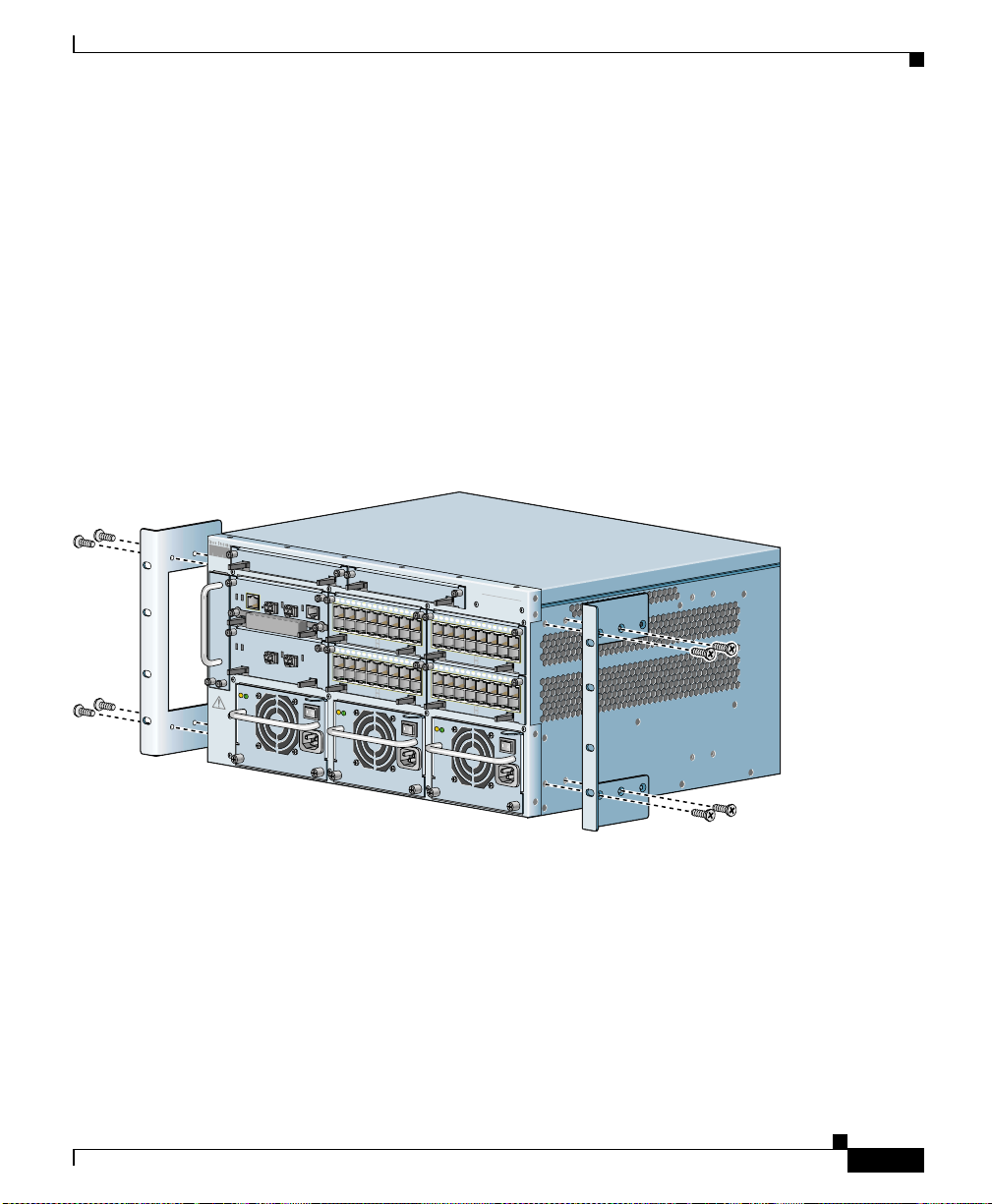
Before you rack-mount the CSS 11506 chassis, determine whether to front-mount
or mid-mount the CSS ch assis i n the rack. The moun ting brac kets are prei nstalled
in the front-m oun ted posi tion o n th e ch assis, as s h own in Figu re 1-4. They are
ready for installation in the equipment cabinet, as described in “Rack-Mounting
the CSS 11506 Chassis”. To mid-mount the moun tin g b ra ckets to the ch ass is,
proceed to “Mid-M oun ting t he CSS 1 150 6 Mou nti ng Bra cket s”.
Figure 1-4 Front-Mounting Position of the CSS 11506 Mounting Brackets
CSS506-SM
CSS506-SM
1
2
3
4
LINK
5
6
7
8
9
10
1
1
1
2
13
14
1
CON
SOLE
System Control
CSS5-10M-16FE
1
2
3
4
LINK
CSS5-10M-16FE
Gigabit Ethernet
A
C
D
C
O
K
O
K
1
0
0
-
2
4
0
V
~
5
A
5
0
-
6
0
H
z
5
LINK
DPLX
LINK
DPLX
5
6
16 Fast Ethernet
7
8
9
10
1
1
12
13
1
4
15
LINK
DPLX
LINK
DPLX
16 Fast Ethernet
1
0
0
-
2
4
0
V
~
5
A
5
0
-
6
0
H
z
1
2
CSS5-10M-16FE
1
2
CSS5-10M-16FE
A
C
D
O
K
O
CISCO 11500
C
SERIES
O
N
T
E
N
T
S
E
R
V
I
C
E
S
S
W
I
T
C
3
4
5
3
4
5
C
K
H
6
7
8
9
10
11
12
1
3
1
4
15
LINK
DPLX
LINK
DPLX
6
16 Fast Ethernet
7
8
9
10
1
1
12
1
3
14
1
5
LINK
DPLX
LINK
DPLX
16 Fast Ethernet
1
0
0
-
2
4
0
V
~
5
A
5
0
-
6
0
H
z
C
A
U
T
IO
DISCONNECT ALL
POWER SOURCES
BEFORE SERVICING
7
8
1
2
4
5
PS1
PS2
MANAGEMENT
10BASE-T
LINK/ACT
DUPLEX
STATUS
GE 1
LINK
GE 2
PCMCIA
SLOT 1
CSS5-SCM-2GE
SLOT 0
STATUS
GE 1
LINK
GE 2
CSS5-10M-2GE
N
A
C
D
C
O
K
O
K
3
6
PS3
Installing the CSS 11506
59540
78-13884-03
This section covers:
• Mid-Mounting the CSS 1 1506 M ou nting Bra ckets
• Rack-Mounting the CSS 1 150 6 C hassi s
Cisco 11500 Series Content Services Switch Hardware Installation Guide
1-17
Page 46

Chapter 1 Unpacking and Installing the CSS
Installing the CS S 11 506
Mid-Mounting the CSS 11506 Mounting Brackets
To change the location of the mounting brackets on the CSS 11506 chassis from
the front-mount position to the mid-mount position:
1. Remove the four screws securing the mounti ng brac ket from one side of the
chassis, as shown in Figure 1-4.
2. Move the mounting bracket to the mid-mount position on the CSS, lining up
its screw holes with the holes on the side of the chassis. See Figure 1-5.
Figure 1-5 Mid-Mounting the Mounting Brackets on the CSS 11506
CSS506-SM
CSS506-SM
1
2
3
4
LINK
5
6
7
8
9
10
1
1
12
13
14
CON
SO
LE
System Control
CSS5-10M-16FE
1
2
3
LINK
CSS5-10M-16FE
Gigabit Ethernet
A
C
D
C
O
K
O
K
1
0
0
-
2
4
0
V
~
5
A
5
0
-
6
0
H
z
15
LINK
DPLX
LINK
DPLX
4
5
6
16 Fast Ethernet
7
8
9
10
11
12
1
3
1
4
1
5
LINK
DPLX
LINK
DPLX
16 Fast Ethernet
1
0
0
-
2
4
0
V
~
5
A
5
0
-
6
0
H
z
1
CSS5-10M-16FE
1
CSS5-10M-16FE
A
C
D
O
K
O
CISCO 11500
C
SERIES
O
N
T
E
N
T
S
E
R
V
I
C
E
S
S
W
I
T
C
2
3
4
5
2
3
4
5
C
K
H
6
7
8
9
10
11
1
2
1
3
14
15
LINK
DPLX
LINK
DPLX
6
16 Fast Ethernet
7
8
9
1
0
11
12
13
14
15
LINK
DPLX
LINK
DPLX
16 Fast Ethernet
1
0
0
-
2
4
0
V
~
5
A
5
0
-
6
0
H
z
C
A
U
T
IO
DISCONNECT ALL
POWER SOURCES
BEFORE SERVICING
7
8
1
2
4
5
PS1
PS2
MANAGEMENT
10BASE-T
LINK/ACT
DUPLEX
STATUS
GE 1
LINK
GE 2
PCMCIA
SLOT 1
CSS5-SCM-2GE
SLOT 0
STATUS
GE 1
LINK
CSS5-10M-2GE
N
3
6
PS3
GE 2
A
C
D
C
O
K
O
K
59541
1-18
3.
Using a Phillips screwdriver, secure the mounting bracket to the CSS.
4. Repeat steps 1 through 3 to reposition the other mounting bracket on the other
side of the chassis.
To install the chassis in a rack, proceed to the “Rack-Mounting the CSS 1150 6
Chassis”.
Cisco 11500 Series Content Services Switch Hardware Installation Guide
78-13884-03
Page 47

Chapter 1 Unpacking and Installing the CSS
Rack-Mounting the CSS 11506 Chassis
You are ready to insta ll the CSS in the rack. Be fore you instal l the CSS 11506 into
an equipment rack, note the following:
• Always install h eavier equipmen t in the l ow er half of a rack to maintain a lo w
center of gravity. This practice helps prevent the rack from falling over.
• Install rack s tab il iz er s ( if availab le) be f ore y ou mo unt th e ch ass is.
Installing a CSS Module
Warning
At least three people are required to mount the chassis in the equipment rack:
two people are needed to hold the chassis in place while a third person
tightens the mounting screws.
To install the CSS 1 1506 c hassi s in to a n equi pment ra ck :
1. Raise the CSS to the installation height and align the screw holes on the
mounting bracket with the ho les on the e quipmen t rack.
2. Secure each mounting bracket to each side of the rack.
Installing a CSS Module
The modules that you ordered with eit her the CSS 11503 or CSS 11506 cha ssis
are preinstalled . I f you n eed to rese at a module, or remo ve and replace i t, r ef er t o
the following sections:
• Installation Precautions and Restrictions
• Unpacking a CSS Module
• Installing a Module
• Installing a Module
This information applies to the CSS modules only.
If you received an additional module at a later time, it comes with a reference
sheet providing information on the module and how to install it.
78-13884-03
Cisco 11500 Series Content Services Switch Hardware Installation Guide
1-19
Page 48

Installing a CSS Module
Installation Precautions and Restrictions
This section includes background material related to installing a module into the
CSS chassis. Cisco Systems recommends that y ou read the topics in this se ction
before installing a module.
Installation Precautions
Caution Yo u must power down the CSS before insta lling or removing a modu le in a
CSS 11506.
Read and observe the following precautionary information prior to servicing the
CSS.
Chapter 1 Unpacking and Installing the CSS
Warning
Warning
Do not remove or install modules without using appropriate anti-static guard
measures. The CSS includes an anti-static wrist strap in the accessory kit.
Attach the copper tape end of the strap to an unpainted metal surface on the
chassis. You can leave the strap connected to the chassis when you are done.
If you do not power down the CSS, an electrical energy hazard is present within
the chassis. Prior to installing or removing components, remove all metallic
objects from hands and wrists to prevent bridging of live contact points.
1-20
Cisco 11500 Series Content Services Switch Hardware Installation Guide
78-13884-03
Page 49

Chapter 1 Unpacking and Installing the CSS
Module Slot Restrictions
Prior to installing a module in a CSS, see Table 1-3 and Table 1-4 for information
on chassis slot restrictions in the CSS 11503 and CSS 11506. I/O modules include
the Fast Ethernet M odule ( FEM ), G iga bit Eth erne t M odu le (G EM ), Session
Accelerator Module (SAM), a nd Secure Socket Lay er (SSL) module .
Table 1-3 CSS 11503 Chassis Slot Restriction
Slot Number Slot Usage
1 Initial active Switch Control Module (SCM)
2 I/O module
3 I/O module
Table 1-4 CSS 11506 Chassis Slot Restriction
Slot Number Slot Usage
1 Initial active Switch Control Module (SCM)
2 Initial passive SCM or I/O module
3 I/O module
4 I/O module
5 I/O module
6 I/O module
Installing a CSS Module
78-13884-03
Cisco 11500 Series Content Services Switch Hardware Installation Guide
1-21
Page 50

Installing a CSS Module
Figure 1-6 illustrates a fully-configured CSS 11503 and its slot locations.
Figure 1-6 Fully-Configured CSS 11503
MANAGEMENT
10BASE-T
LINK/ACT
DUPLEX
STATUS
GE 1
PCMCIA
SLOT 1
CSS5-SCM-2GE
1
2
3
SLOT 0
1
LINK
2
3
GE 2
4
LINK
5
6
7
8
9
10
11
1
2
13
14
CONS
OLE
System Control
CSS5-10M-16FE
15
LINK
DPLX
LINK
DPLX
16 Fast Ethernet
1
CSS5-10M-16FE
CISCO 11500
C
SERIES
O
N
T
E
N
T
S
E
R
V
I
C
E
S
S
W
I
T
C
2
3
4
5
H
6
7
8
9
10
11
1
2
13
14
15
LINK
DPLX
LINK
DPLX
16 Fast Ethernet
1
2
3
1 Slot location 1 3 Slot location 3
2 Slot location 2
Chapter 1 Unpacking and Installing the CSS
59549
1-22
Cisco 11500 Series Content Services Switch Hardware Installation Guide
78-13884-03
Page 51

Chapter 1 Unpacking and Installing the CSS
Figure 1-7 illustrates a fully-configured CSS 11506 and its slot locations.
Figure 1-7 Fully-Configured CSS 11506
Installing a CSS Module
1
2
3
CSS506-SM
CSS506-SM
1
2
3
4
LINK
5
6
7
8
9
10
1
1
12
13
1
4
C
ONSOLE
System Control
CSS5-10M-16FE
1
2
3
LINK
CSS5-10M-16FE
Gigabit Ethernet
A
C
D
C
O
K
O
K
1
0
0
-
2
4
0
V
~
5
A
5
0
-
6
0
H
z
15
LINK
DPLX
LINK
DPLX
4
5
6
16 Fast Ethernet
7
8
9
10
1
1
12
1
3
14
15
LINK
DPLX
LINK
DPLX
16 Fast Ethernet
1
0
0
-
2
4
0
V
~
5
A
5
0
-
6
0
H
z
1
2
CSS5-10M-16FE
1
2
CSS5-10M-16FE
A
C
D
O
K
O
CISCO 11500
C
SERIES
O
N
T
E
N
T
S
E
R
V
I
C
E
S
S
W
I
T
C
3
4
5
3
4
5
C
K
H
6
7
8
9
1
0
11
12
13
14
15
LINK
DPLX
LINK
DPLX
6
16 Fast Ethernet
7
8
9
10
11
1
2
1
3
1
4
15
LINK
DPLX
LINK
DPLX
16 Fast Ethernet
1
0
0
-
2
4
0
V
~
5
A
5
0
-
6
0
H
z
C
A
U
T
IO
DISCONNECT ALL
POWER SOURCES
BEFORE SERVICING
7
8
1
2
4
5
PS1
PS2
MANAGEMENT
10BASE-T
LINK/ACT
DUPLEX
STATUS
GE 1
LINK
GE 2
PCMCIA
SLOT 1
CSS5-SCM-2GE
SLOT 0
STATUS
GE 1
LINK
GE 2
CSS5-10M-2GE
N
A
C
D
C
O
K
O
K
3
6
PS3
4
5
6
1 Slot location 1 4 Slot location 4
2 Slot location 2 5 Slot location 5
3 Slot location 3 6 Slot location 6
59550
78-13884-03
Cisco 11500 Series Content Services Switch Hardware Installation Guide
1-23
Page 52

Installing a CSS Module
Unpacking a CSS Mo dule
To unpack a CSS module:
1. Verify that the module is the mode l you ordere d by checki ng the mode l
number listed on the side of the shipp ing carton .
2. Remove the module from the shipping carton, leaving it in its anti-static bag.
3. Put on the anti-static strap provided with your CSS. For example, wear the
anti-static wrist strap (included in th e accessory kit) and stick the copper -tape
end of the strap to an unpainted metal surface on the chassis. Make sure that
the wrist strap makes good contact with your skin.
4. Remove the module from the anti-static shielding bag and inspect it for
damage.
Always hold the module by the faceplate, being careful not to touch the
components. If the module appears to be damaged, return it to the anti-static
bag, repack it in the shipping c art on, a nd cont ac t you r loca l su ppli er.
5. To install a module into the CSS chassis, see “Installing a Module”.
Chapter 1 Unpacking and Installing the CSS
Installing a Module
Caution Yo u must power down the CSS before insta lling or removing a modu le in a
CSS 11506.
Cisco 11500 Series Content Services Switch Hardware Installation Guide
1-24
78-13884-03
Page 53

Chapter 1 Unpacking and Installing the CSS
CISCO
11500
S
E
R
IE
S
CONTENT SERVICES SWITCH
15
14
13
1
2
11
10
D
P
L
X
1
6
F
a
s
t E
th
e
rn
e
t
D
P
L
X
To install a module:
1. Properly ground yourself prior to handling the module. For example, wear the
anti-static wrist strap (included in th e accessory kit) and stick the copper -tape
end of the strap to an unpainted metal surface on the chassis. Make sure that
the wrist strap makes good contact with your skin.
2. If necessary, power down the CSS.
3. Locate an open slot in the ch ass is for th e modul e. See Table 1-3 to identify
possible slots for the module. If n ecessary, use a #1 Phillips screwdriver to
remove a blank panel from the chassis to expose a slot for the module .
4. Insert the module into the board guides at the left and right of the slot. Make
sure that the ejectors are fully extended outward. Slide the module into the
chassis by pressing firm ly a t t he l eft and r i ght of the face plate a s s hown in
Figure 1-8.
Figure 1-8 Installing a Module into a CSS Chassis
Installing a CSS Module
1
1
2
3
4
5
6
7
8
9
1
0
1
1
1
2
1
3
1
4
1
E
F
6
-1
M
0
-1
5
S
S
2
C
L
IN
K
D
P
L
X
L
IN
K
D
P
L
X
1 Spring-loaded screw (one on
each side)
Close both ejectors simultaneously to seat the module connector into the
5.
backplane.
6. Using a Phillips screwdri v er, tighten the spring-loa ded scre ws on the front o f
5
t
e
rn
e
th
t E
s
a
F
6
1
2 Ejector (one on each side), extend
outward during insert ion
59542
the module facepl a te.
78-13884-03
7. Reboot the chassis to activate the module.
Cisco 11500 Series Content Services Switch Hardware Installation Guide
1-25
Page 54

Installing a CSS Module
Installing a Passive SCM in a CSS 11506
Yo u can in stall a passive SCM in a CSS 1 150 6 chassi s. A passive module is a
stand-by module in c ase of a n ac tive module fail ure . A s i mpl em en ted in
WebNS 5.10 and greater, if the active SCM fails:
1. The CSS reboots and connecti ons are te rmina ted.
2. The CSS restores all configurations using the startup-config file.
3. The passive SCM becomes active automatically.
Note Passive modules do not load share proc essing func tions with th e active module.
To install a passive SCM:
1. Properly ground yo urse lf prio r t o ha nd lin g the mod ul e.
2. As defined in Table 1-3, SCMs are re stricted to slots 1 or 2.
3. If necessary, power down the CSS.
4. If necessary, remove a blank panel from the chassis to expose the slot.
5. Insert the module into the board guides at the left and right of the slot and
slide it into the chassis by pressing f irmly at the left and right o f the facepla te.
Chapter 1 Unpacking and Installing the CSS
1-26
6. Extend both ejectors simultaneously to seat the module connector into the
backplane.
7. Using a Phillips screwdri v er, tighten the spring-loa ded scre ws on the front o f
the module facepl a te.
Cisco 11500 Series Content Services Switch Hardware Installation Guide
78-13884-03
Page 55

Chapter 1 Unpacking and Installing the CSS
8. Optionally, you can install the PCMCIA cover to the front of the disk slots
and secure it with its two spring-l oade d screws, as shown in Figure 1-9 . The
cover protects the disks in the SCM.
Figure 1-9 Installing a PCMCIA Cover on an SCM
9. Reboot the CSS to initialize the passive SCM.
10. T o copy the boot configuration from the active SCM to the passive SCM, use
the passive sync command in boot configu ratio n m ode. For more
information, refer to the Content Services Switch Administration Guide.
Installing a CSS Module
MANAGEMENT
10BASE-T
L
IN
K
/A
C
T
D
S
U
T
A
P
T
L
U
E
S
X
G
E
L
1
IN
K
G
L
E
IN
2
E
G
-2
M
C
-S
P
C
M
C
IA
5
S
S
L
O
T
1
S
C
S
L
O
T
0
K
l
CO
N
SO
tro
LE
n
o
C
m
te
s
y
S
59602
78-13884-03
Cisco 11500 Series Content Services Switch Hardware Installation Guide
1-27
Page 56

Installing a CSS Module
Chapter 1 Unpacking and Installing the CSS
1-28
Cisco 11500 Series Content Services Switch Hardware Installation Guide
78-13884-03
Page 57

CHAPTER
2
Cabling the CSS
This chapter describes the indi vidual CSS interfaces, ho w to cable the CSS and its
interfaces, how to attach a c onso le f or c ons ole mana ge ment , and how to conn ec t
the AC power cord or the DC p ower cord ( CSS 1 150 3 and CSS 115 06 only ).
This chapter also describes the CSS LEDs an d connector s. The info rmation in this
chapter applies t o t he CSS 11501, CSS 11503, and CSS 115 06, exc ept whe re
noted.
This chapter contains the following sections:
• Cabling the CSS 11501
• Cabling the CSS 11503 an d C SS 11506 M odul es
• Connecting the Console
• Connecting the Chassis to Ground
78-13884-03
• Connecting the Power Cord
Cisco 11500 Series Content Services Switch Hardware Installation Guide
2-1
Page 58

Cabling the CSS 11501
Cabling the CSS 11501
A CSS 11501 is a f ull y in tegrat ed p l atfo rm , de livering transp ort an d a pp lica tio n
(layers 4-7) services for Interne t and Intran et data centers. The CSS 11501 is a
single-rack-unit, w ith 6-Gbps ag gregate thr oughput . The integrat ed compo nents
in the CSS 11501 contribute to the overall processing and memory needs for flow
set up and flow forwarding.
The fully integrated CSS 11501 is responsi ble for the following functions:
• System powerup and boot control
• Centralized routin g ta ble m an agem ent
• System-wide connection management
• An interface to an external Network Management Station
• Disk management
• An external RS-232 interface
The CSS 11501 configuration supports :
• 288 MB RAM memory (256 MB of usabl e memory)
Chapter2 Cabling the CSS
2-2
• T wo PCMCIA slots for a hard or flash disk drive for the system software, and
logging and off-line system files. A cover is preinstalled over the slots.
• RJ-45 RS-232 Console port
• RJ-45 10-Mbps half-dup lex Ethernet managem ent conne ctor
• RJ-45 RS-232 Diag connector (reserved for field service diagnostic use only).
• Eight auto-sensing 10/100-Mbps Ethern et (10B ASE-T/100B A SE-TX) interfaces
Cisco 11500 Series Content Services Switch Hardware Installation Guide
78-13884-03
Page 59

Chapter 2 Cabling the CSS
Cabling the CSS 11501
• SFP GBIC (1000BASE-SX or LX) with LC-type connectors. The GBIC can
use either:
–
Longwave-length SFP GBICs (CSS5-GBIC-LX). The longwave length
transceiver (1000BASE-LX) can reach 550 meters fo r all mul timod e
media types. For sing le- mod e fiber, the distan ce i s 5,000 m ete rs.
–
Shortwave-length SFP GBICs (CSS5-GBIC-SX). The transceiver
distance can reach fr om 220 mete rs to 500 met ers, depe nding on the
quality of the fiber.
Warning
Because invisible radiation may be emitted from the aperture of the port when
no fiber cable is connected, avoid exposure to radiation and do not stare into
open apertures.
The CSS 11501 fro nt p anel L E Ds indi cate cha ssis an d con figuratio n stat us:
• Two status module LEDs indicat ing power and device readi ness
• Link/Act and Duplex LEDs for the Ethernet Management port
• Link/Act and Duplex LEDs for each Ethernet port
• Link/Act LED for the SFP GBIC
78-13884-03
Cisco 11500 Series Content Services Switch Hardware Installation Guide
2-3
Page 60

Cabling the CSS 11501
CSS 11501 Connectors and LEDs
The CSS 11501 has all connectors and LEDs on the chassis front panel. Figure 2-1
illustrates the connecto rs and LEDs on the CSS 11501.
For information on the connector pinouts, refer to Appendix B, Cable Connector
Pinouts.
Figure 2-1 CSS 11501 Connectors and LEDs
Chapter2 Cabling the CSS
6
7
8
L
I
N
K
D
P
L
X
L
I
N
K
D
P
L
X
L
I
N
K
D
P
L
X
L
IN
K
D
P
L
X
L
IN
K
D
P
L
X
L
I
N
K
D
P
L
X
L
I
N
K
D
P
L
X
L
IN
K
D
P
L
X
C
I
S
C
O
1
1
5
0
0
CONTENT SERVICES SWITCH
1
2
3
4
10/100
5
6
7
10/100
SERIES
G
E
L
I
N
K
8
6 RJ-45 Ethernet 10BASE-T/100BASE-TX connectors
1 through 8
1
1 Bicolor status LED
(green and red)
1
10
2
4
3
S
T
A
T
U
S
C
O
N
S
O
L
E
11
5b
L
I
N
K
/
A
C
T
D
U
P
L
E
X
P
C
M
C
I
A
5a
9
2 Amber status LE D 7 LC-type SFP GBIC (optional)
3 RJ-45 RS- 232 Co nsol e con ne ctor 8 Link LED for SFP GBIC
4 10-Mbps half-duplex Ethernet
management c onn ect or
9 RJ-45 RS-232 D iag c onn ect or f or field servi ce
diagnostic use only. (A connector cover is provided.
Removing the cover voids the warranty.)
5a PCMCIA slot 0 contai ning a flash or
10 PCMCIA s l o t c ove r
hard disk
5b PC MCIA slot 1 (shown emp ty) for
11 Recessed button (reserved fo r field se rv ice us e onl y )
optional installation of a second flash
or hard disk
1. The Ethernet Link/Act LED and Duplex LED are located at the top o f each RJ -45 Eth ernet connector and are not visi ble in thi s
illustration.
78930
2-4
Cisco 11500 Series Content Services Switch Hardware Installation Guide
78-13884-03
Page 61

Chapter 2 Cabling the CSS
Table 2-1 describes the CSS 11501 LEDs and their ind ications.
Table 2-1 CSS 11501 LED Descriptions
Cabling the CSS 11501
LED Name Color State Indicates
Status (left) Green Solid The CSS 11501 is ready.
Variable
Disk activity is occurring.
blink
Slow blink The CSS 11501 fail ed.
Red Solid The CSS 11501 failed the
power-up self test during the boot
process.
Slow blink The CSS 11501 failed.
No color Off The CSS 11501 failed and has no
power.
Status (right) Amber Fast blink The CSS 11501 is run ning
power-up self test.
Slow blink The CSS 11 501 is o ffline an d
active.
Link/Act
for the Ethernet
Management Port
Green Off There is no link.
On The link is established but there is
no activity.
Blinking The link is established with
transmit or receive activity.
Duplex
for Ethernet
Management Port
Link/Act
for Ethernet Port
Green Off Port is operating at hal f duplex.
On Port is operati ng at full dup lex.
Green Off No link established.
On Link establis hed but no activity.
Blinking Link establ ished with transmit or
receive activity.
Duplex
for Ethernet Port
Green Off Port is operating at hal f duplex.
On Port is operati ng at full dup lex.
78-13884-03
Cisco 11500 Series Content Services Switch Hardware Installation Guide
2-5
Page 62
Cabling the CSS 11501
Table 2-1 CSS 11501 LED Descriptions (continued)
LED Name Color State Indicates
Link /Act
for the Gigabit
Ethernet Po rt
Green Off There is no link.
On The link exists and
synchronization is ac hieved.
Blinking The link is established with
transmit or receive activity.
Chapter2 Cabling the CSS
2-6
Cisco 11500 Series Content Services Switch Hardware Installation Guide
78-13884-03
Page 63

Chapter 2 Cabling the CSS
Cabling the CSS 11503 and CSS 11506 Modules
Cabling the CSS 11503 and CSS 11506 Modules
The CSS 11503 and CSS 11506 modules have connectors and LEDs on their front
panels. The following sections describe:
• CSS 11503 and CSS 11506 Module Overview
• Switch Control Module Connectors and LEDs
• Fast Ethernet Module Connec tors and LE Ds
• Gigabit Ethernet M od ule Co nnecto rs an d L EDs
• Session Accelerat or Modul e L EDs
• Secure Socket Layer (SSL) Module LEDs
For information on the connector pinouts, refer to Appendix B, Cable Connector
Pinouts.
CSS 11503 and CSS 11506 Module Overview
78-13884-03
The CSS 11503 and CSS 11506 are compact mod ular platfo rms, delivering
transport and application (layers 4-7) services for Internet and Intranet data
centers. A CSS is a fully-distributed architecture with all modules in the system
contributing to the overall processing and memory ne eds for flow set up.
Performance increases incrementally as you add modules, and the modules
balance the overall traffic load.
• The Cisco 11506 is a five-rack unit, su ppo rting six-sl ots, wit h 40-Gb ps
aggregate throughpu t. The CSS 1 1506 req uire s a t le as t one Switc h C ontr ol
Module (SCM) and may be co nfigured with a secon d SCM in st andby mode
for redundancy. With the required SCM in one slot, the CSS 11506 has five
additional slots supporting any combin ation of I/O mod ules.
• The Cisco 11503 is a two-rack-uni t, suppor ting thre e-slots, w ith 20-Gbp s
aggregate throughpu t. The CSS 1 1503 req uire s a n SCM a nd a ccom mod ate s
any two of the other m odu les.
Though all modules participate in flow setup, they differ primarily in control
functions, perf orm ance , a nd I/O . Ea ch C SS 11500 m odule c ons ists of o ne
high-speed MIPS RISC processor for flow-setup, one network processor for flow
forwarding, one policy co-proc essor fo r search ope rations an d a maximu m of
288 MB of RDRAM (up to 256 MB of usab le memor y).
Cisco 11500 Series Content Services Switch Hardware Installation Guide
2-7
Page 64

Cabling the CSS 11503 and CSS 11506 Modules
The CSS 11506 not only supports redun dancy in SCMs but also supports
redundant power supplies a nd re du ndant Swit ch M odul es (2 0 Gb ps e ach ).
The CSS modules are as follows:
• 144 MB or 288 MB (128 MB or 256 MB of usab le me mory) Swit ch Cont rol
Module (SCM) with:
–
Two 1000-Mbps Etherne t (1 000 BASE-SX or L X ) sma ll- form facto r
pluggable gigabit interface converters (SFP GBICs) with LC-type
connectors.
–
T wo PCMCIA slots for a hard or flash disk drive for the system software,
and logging and off-line system files.
–
RJ-45 RS-232 Console port
–
1 RJ-45 10-Mbps half-dupl ex Ethernet mana gement connect or.
• Switch Module (SM). A n SM provides conn ectivity among the SCM and
IOMs.
–
The CSS 11503 has a single integrated SM. A single SM has an aggregate
throughput of 20 Gbps.
Chapter2 Cabling the CSS
2-8
–
The CSS 11506 has two removable SMs that share the switching
functions. Two SMs provide 40 Gbps aggr egate thro ughp ut. As
implemented in WebNS 5.1 0 and gre ater, if one SM fails, the CSS
reboots and continues to operate through the other SM.
• T w o slots in the CSS 11503 and five slots in the CSS 11506 are configurable
with:
–
Fast Ethernet Modules tha t provide eit her 8 or 16 aut o-sens ing
10/100-Mbps Ethe rn et (
–
Gigabit Ethernet Mod ul es pr ovides up to two 100 0-Mbp s E the rnet
10BASE-T/100BASE-TX) RJ-45 p orts.
(1000BASE-SX or LX) SFP GBICs with LC-type connectors.
–
A Session Accelerator Module (SAM) that provides a cost-effective way
to add flow performance when additional connectivity is not required.
Using the same flow setup and forwarding processors as the I/O modules,
it provides the flexibility to optimize the CSS for port density and
performance.
Cisco 11500 Series Content Services Switch Hardware Installation Guide
78-13884-03
Page 65

Chapter 2 Cabling the CSS
Figure 2-2 illustrates a fully-configured CSS 11503 and its components.
Figure 2-2 CSS 11503 Content Services Switch
Cabling the CSS 11503 and CSS 11506 Modules
–
A Secure Socket La ye r ( SSL ) m o du le th at fu n ctio ns as a n SSL s erver by
adding security ser vices be tween the Web browsers (the client) and
HTTP servers. The SSL module is responsible for all user authentication,
public/private key generation, certificate management, and packet
encryption and de cryp tio n f unct ions be twee n t he cl ie nt a nd the serv er.
Each SSL module terminates SSL connections received from a client.
The CSS 11503 supports a maximum of two SSL modules and the CSS
11506 supports a maximu m of fou r SSL m odules. For information on SSL
commands and f unc tions, r efer to t he Cisco Con tent Servic es Switch
Advanced Configuratio n Gui d e.
–
An additional SCM to serve as a passive redundant module.
78-13884-03
M
A
N
A
G
E
M
E
N
T
1
0
B
A
S
E
-
T
L
IN
K
/
A
C
T
D
S
U
T
A
P
T
L
U
E
S
X
G
E
1
L
1
IN
K
2
3
4
G
L
E
IN
2
5
K
E
G
-2
M
C
-S
P
C
M
C
IA
5
S
S
L
O
T
1
S
C
1
2
3
S
L
O
T
0
6
7
8
9
1
0
1
1
1
2
1
3
1
4
1
l
E
o
C
O
F
N
SO
tr
L
E
6
n
-1
o
M
C
0
m
-1
5
te
s
S
y
S
S
C
5
L
IN
K
D
P
L
X
L
IN
K
D
P
L
X
C
IS
C
O
1
1
5
0
0
C
S
O
E
R
N
I
E
T
S
E
N
T
S
E
R
V
IC
E
S
SW
IT
C
1
2
3
4
t
e
E
n
F
r
6
e
-1
h
t
M
0
t E
-1
s
5
a
S
F
S
6
C
1
H
5
6
7
8
9
1
0
1
1
1
2
1
3
1
4
1
5
t
e
L
IN
K
rn
D
e
P
L
X
th
L
IN
K
E
D
P
L
t
X
s
a
F
6
1
1
2
3
1 Slot 1 for the SCM only 3 Slot 3 for an I/O module
2 Slot 2 for an I/O module
Cisco 11500 Series Content Services Switch Hardware Installation Guide
59549
2-9
Page 66

Cabling the CSS 11503 and CSS 11506 Modules
Figure 2-3 illustrates a fully-configured CSS 11506 and its components.
Figure 2-3 CSS 11506 Content Services Switch
Chapter2 Cabling the CSS
2 4 5
CSS506-SM
MANAGEMENT
10BASE-T
LINK/ACT
DUPLEX
STATUS
GE 1
LINK
PCMCIA
SLOT 1
CSS5-SCM-2GE
C
A
U
T
IO
DISCONNECT ALL
POWER SOURCES
BEFORE SERVICING
7
8
1
2
4
5
PS1
PS2
SLOT 0
STATUS
GE 1
LINK
CSS5-10M-2GE
N
A
C
D
C
O
K
O
K
3
6
PS3
1
3
CSS506-SM
1
2
3
GE 2
GE 2
4
LINK
5
6
7
8
9
10
1
1
12
1
3
14
CON
SO
LE
System Control
CSS5-10M-16FE
1
2
3
LINK
CSS5-10M-16FE
Gigabit Ethernet
A
C
D
C
O
K
O
K
1
0
0
-
2
4
0
V
~
5
A
5
0
-
6
0
H
z
15
LINK
DPLX
LINK
DPLX
4
5
6
16 Fast Ethernet
7
8
9
1
0
11
12
13
14
15
LINK
DPLX
LINK
DPLX
16 Fast Ethernet
1
0
0
-
2
4
0
V
~
5
A
5
0
-
6
0
H
z
1
2
CSS5-10M-16FE
1
2
CSS5-10M-16FE
A
C
D
O
K
O
CISCO 11500
C
SERIES
O
N
T
E
N
T
S
E
R
V
I
C
E
S
S
W
I
T
C
3
4
5
3
4
5
C
K
H
6
7
8
9
1
0
11
12
1
3
14
15
LINK
DPLX
LINK
DPLX
6
16 Fast Ethernet
7
8
9
10
11
12
1
3
1
4
1
5
LINK
DPLX
LINK
DPLX
16 Fast Ethernet
1
0
0
-
2
4
0
V
~
5
A
5
0
-
6
0
H
z
6
1 Fan modul e 4 Slot 2 for an SCM or I/O module
2 Slot 1 for the SCM 5 Slot 6
1
3 Switch Modules in slots 7 and 8 6 Power supplies 1, 2, and 3
1. Slots 3 through 6 are for I/O modules, including SAMs and SSL modules.
59527
2-10
Cisco 11500 Series Content Services Switch Hardware Installation Guide
78-13884-03
Page 67

Chapter 2 Cabling the CSS
Cabling the CSS 11503 and CSS 11506 Modules
Switch Control Module Connectors and LEDs
The Switch Control Module (SCM), model CSS5-SCM-2GE, provides master
control and is re spo nsible f or the f ol lowing funct ions:
• System powerup and boot control
• Centralized routin g ta ble m an agem ent
• System-wide connection management
• An interface to an external Network Management Station
• Disk management
• An external RS-232 interface
A CSS supports a maximum of two SCMs, one active and one passive.
The Switch Control Module c ontains the fol lowing connect ors and slots:
• 1 RJ-45 10-Mbps half-dupl ex Ethernet mana gement connect or.
• 1 RJ-45 RS-232 C onso le co nnect or.
• 1 RJ-45 RS-232 Di ag c on ne ctor ( re served f or field se rvic e dia gno stic u se
only).
• 2 SFP GBICs (1000BASE-SX or LX) with LC-type connectors.
78-13884-03
• T w o PCMCIA slots for a hard disk or flash disk. A cover is preinstalled over
the slots.
Note The SCM can have a maximum of two disk drives.
The SCM front pa nel L EDs in dic ate m odu le a nd c on figuration stat us:
• Two status module LEDs indicat ing power and mod ule readi ness
• Link/Act and Duplex LEDs for the Et herne t manage ment por t
• Link LEDs for each SFP GBIC
Warning
Because invisible radiation may be emitted from the aperture of the port when
no fiber cable is connected, avoid exposure to radiation and do not stare into
open apertures.
Cisco 11500 Series Content Services Switch Hardware Installation Guide
2-11
Page 68

Cabling the CSS 11503 and CSS 11506 Modules
Figure 2-4 illustrates the SCM front panel connectors, PCMCIA slots, and LEDs.
Figure 2-4 Switch Control Module Connectors and LEDs
2
1
10 11a12
S
E
-2G
M
C
5-S
S
S
C
345
MANAGEMENT
L
IN
T
A
T
U
S
P
C
M
C
IA
10BASE-T
K
/A
C
Chapter2 Cabling the CSS
6
7
11b
T
D
U
P
L
E
X
G
E
L
1
IN
K
G
L
E
IN
2
K
S
L
O
T
1
S
L
O
T
0
C
O
N
S
O
L
E
trol
on
C
ystem
S
9
8
78993
1 10-Mbps half- duplex Ethern et mana gement
8 RJ-45 RS-232 Cons ole co nnector
connector
2 Bicolor sta tus L E D (g re en a nd red) 9 RJ-45 RS-232 Diag connecto r for field
service diagnostic use on ly. (A connector
cover is pro vid ed. Rem oving the cover voids
the warranty.)
3 Amber sta tus LED 10 PCMCIA s lo t c over
4 Link/Act LE D 11a PCMCIA slot 0 conta ining a fla sh or hard
disk
5 Duplex LED 11b PCMCIA slot 1 (shown empty) for optiona l
installation of a second fl ash or hard di sk
6 LC-type SFP GBIC (one of two) 12 Recessed button (reserved for field service
7 Link LED for the associated SFP GBIC on
use only)
the left
Cisco 11500 Series Content Services Switch Hardware Installation Guide
2-12
78-13884-03
Page 69

Chapter 2 Cabling the CSS
Table 2-2 describes the SCM LEDs and th eir indic ations .
Table 2-2 Switch Control Module LED Descriptions
Cabling the CSS 11503 and CSS 11506 Modules
LED Name Color State Indicates
Status (left) Green Solid The module is ready.
Variable
Disk activity is occurring.
blink
Slow blink Another CSS module failed.
Red Solid The module failed the power-up
self test during the boot proces s.
Slow blink The module failed.
No color Off The module failed and has no
power.
Status (right) Amber Fast blink The module is r unnin g p ower-up
self test.
Slow blink The module is offline and active.
Solid The modu le is online an d not
active (passive SCM).
Link/Act
for the Ethernet
Management Port
Green Off There is no link.
On The link is established but there is
no activity.
Blinking The link is established with
transmit or receive activity.
Link
for each Gigabit
Ethernet Po rt
Green Off There is no link.
On The link exists and
synchronization is ac hieved.
Blinking The link is established with
transmit or receive activity.
78-13884-03
Cisco 11500 Series Content Services Switch Hardware Installation Guide
2-13
Page 70
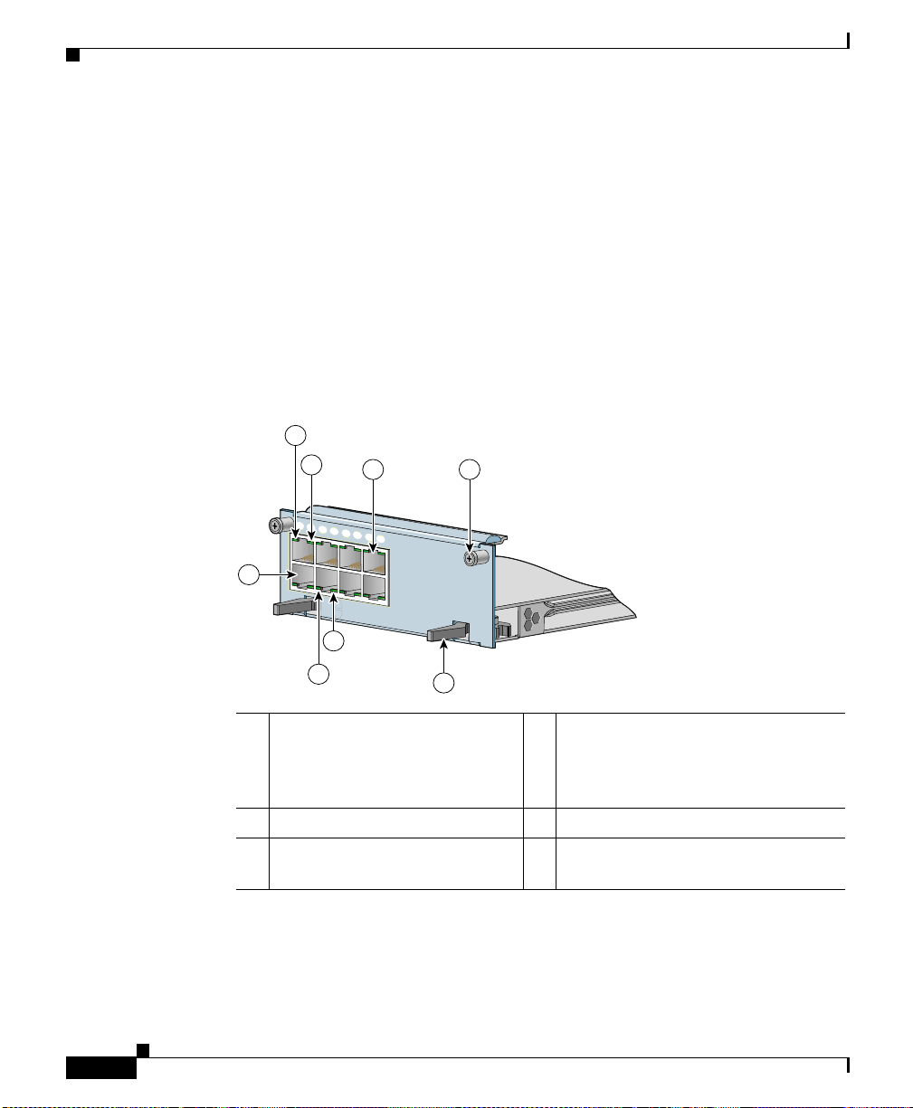
Cabling the CSS 11503 and CSS 11506 Modules
Fast Ethernet Module Connectors and LEDs
The FEM is available in two models:
• Model CSS5-IOM-8F E co nt ains 8 au to-se nsin g R J-45 Fast Eth erne t
10/100-Mbps 10BASE-T/100BASE-TX c onne ctor s.
• Model CSS5-IOM-16FE contain s 16 auto-se nsing RJ-45 Fast Ethern et
10/100-Mbps 10BASE-T/100BASE-TX c onne ctor s.
Each connector has Link and Duplex LEDs. The LEDs indicate the module and
network status. Figure 2-5 illustrates the LEDs and connectors on the 8-port FEM.
Figure 2-5 8-Port Fast Ethernet Module Connectors and LEDs
2
3
1
2
3
4
5
6
4 5
7
8
Chapter2 Cabling the CSS
2-14
1
CSS5-10M-8FE
LINK
DPLX
LINK
DPLX
3
2
1 RJ-45 Ethernet
10BASE-T/100BASE-TX
connector 1 (connector 2 is
shown directly above it)
8 Fast Ethernet
6
4 RJ-45 Ethernet
10BASE-T/100BASE-TX connector
8 (connector 7 is shown dir ectly
below it)
2 Link LED (on each conne ctor) 5 Spring-loaded screw (one of two)
3 Duplex LED (on each
6 Ejector (one of two)
connector)
Figure 2-6 illustrates the LEDs and connectors on the 16-port FEM.
Cisco 11500 Series Content Services Switch Hardware Installation Guide
59534
78-13884-03
Page 71

Chapter 2 Cabling the CSS
Figure 2-6 16-Port Fast Ethernet Module Connectors and LEDs
1
2
3
1
2
3
CSS5-10M-16FE
CSS5-10M-16FE
Cabling the CSS 11503 and CSS 11506 Modules
4
4
5
6
7
8
9
10
11
12
13
14
15
LINK
LINK
DPLX
DPLX
LINK
LINK
DPLX
DPLX
3
16 Fast Ethernet
16 Fast Ethernet
5
59533
2
1 RJ-45 Ethernet
10BASE-T/100BASE-TX
connector 1 (connector 2 is
shown directly above it)
6
4 RJ-45 Ethernet
10BASE-T/100BASE-TX connector
16 (connector 15 i s sh own directl y
below it)
2 Link LED (on each conne ctor) 5 Spring-loaded sc rew (one o f two)
3 Duplex LED (on each
6 Ejector (one of t wo)
connector)
78-13884-03
Cisco 11500 Series Content Services Switch Hardware Installation Guide
2-15
Page 72

Cabling the CSS 11503 and CSS 11506 Modules
Table 2-3 describes the FEM LEDs and t heir indica tions.
Table 2-3 Fast Ethernet Module LED Descriptions
LED Name Color State Indicates
Link Green Off No link established
Duplex Green Off Port is operating at half dupl ex
Note If all of t he FE M Lin k an d D up lex LED s b link sync hro nou sly, the module has
failed.
Chapter2 Cabling the CSS
On Link established but no activity
Blinking Link established with transmit or receive
activity
On Port is operating at full duplex
Gigabit Ethernet Module Connectors and LEDs
The Gigabit Ethernet Mod ule (GEM), mo del CSS5-IOM -2GE, co ntain s two
1000-Mbps SFP GBICs with LC-type connectors. The GEM can use either:
• Longwave-length SFP GBICs (CSS5-GBIC-LX). The longwave length
transceiver (1000BASE-LX) can reach 550 meters fo r all mult imod e media
types. For single-mode fiber, the dista nce is 5 ,0 00 meter s.
• Shortwave-length SFP GBICs (CSS5-GBIC-SX). The transceiver distance
can reach from 220 meters to 500 meters, depending on the quality of the
fiber.
Warning
Cisco 11500 Series Content Services Switch Hardware Installation Guide
2-16
Because invisible radiation may be emitted from the aperture of the port when
no fiber cable is connected, avoid exposure to radiation and do not stare into
open apertures.
78-13884-03
Page 73

Chapter 2 Cabling the CSS
The GEM front panel LEDs indicate the network status for each of the connectors
(Link LEDs). Figure 2-7 illustr ates the LEDs a nd connec tors on a GEM.
Figure 2-7 Gigabit Ethernet Module Connectors and LEDs
Cabling the CSS 11503 and CSS 11506 Modules
2
3
S
T
A
T
U
1
S
E
G
-2
M
0
-1
5
S
S
C
G
E
1
4
4
L
IN
K
5
G
L
E
IN
2
K
t
e
n
r
e
th
it E
b
a
ig
G
2
59535
6
1 Bicolor status LED (green and
red)
4 Link LED (next to its
corresponding SFP GBIC)
2 Amber status LED 5 Spring-loa ded screw (one of two)
3 LC-type SFP GBIC (one of two) 6 Ejector (one of two)
Table 2-4 describes the GEM LEDs.
Table 2-4 Gigabit Etherne t Module LED Desc riptions
LED Name Colo r State Indicates
Status (left) Green Solid The module is ready.
Red Solid The module failed the power-up self
test during the boo t pr ocess.
Slow blink The module failed.
No color Off The module failed and has no power.
Status (right) Amber Fast blink The module is runn ing power-up self
test.
Slow blink The module is offline and active.
Solid The module is online and not active.
78-13884-03
Cisco 11500 Series Content Services Switch Hardware Installation Guide
2-17
Page 74
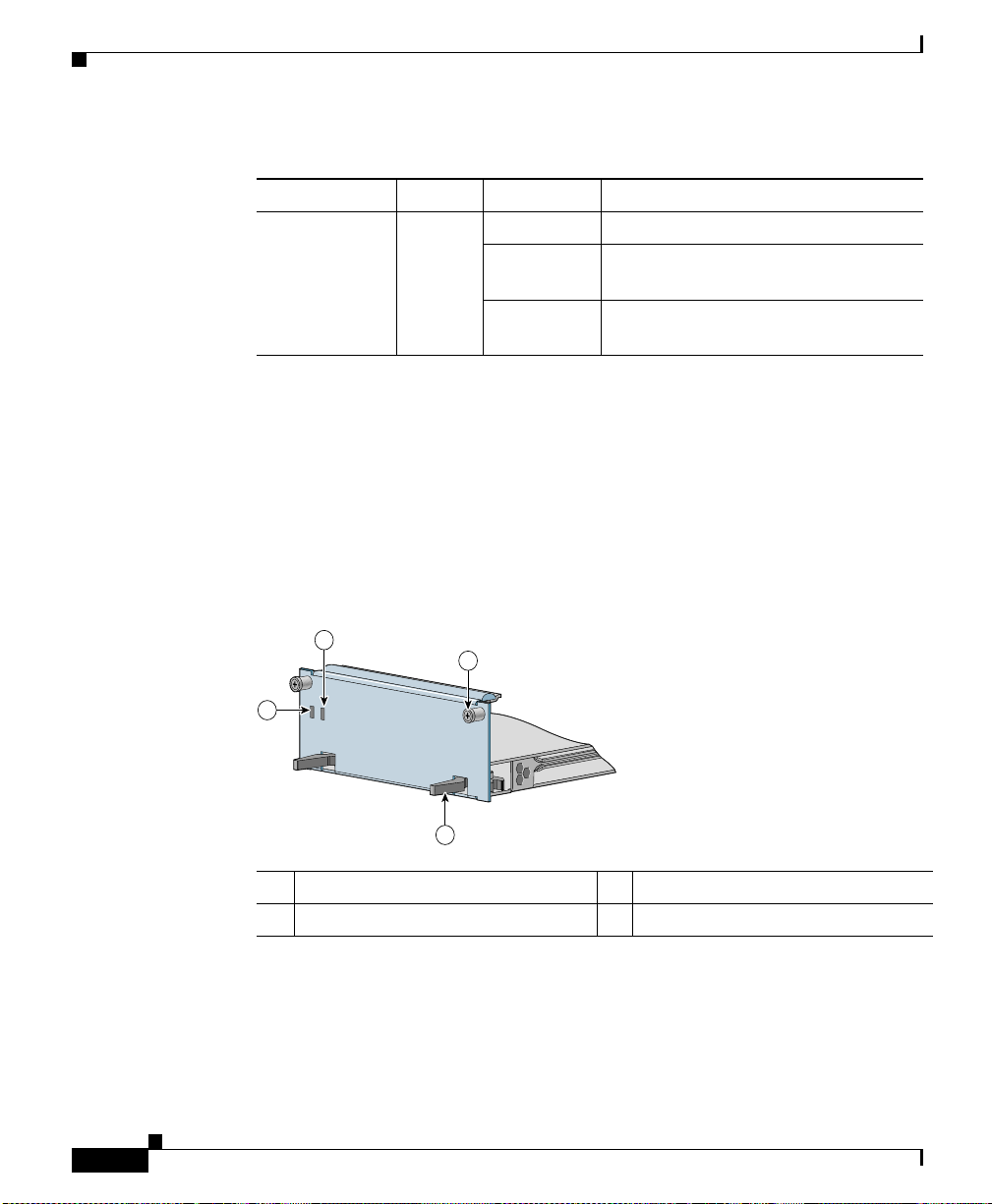
Cabling the CSS 11503 and CSS 11506 Modules
Table 2-4 Gigabit Ethernet Module LED Descriptions (continued)
LED Name Colo r State Indicates
Link Green Off There is no link.
On The link exists and synchronization is
Blinking The link is established with transmit
Session Accelerator Module LEDs
The Session Accelerator Module (SAM), model CSS5-SAM, is used with the
SCM to provide additional processing support for session setup. The SAM front
panel LEDs indicate its operational status. The SAM has no connectors.
Figure 2-8 illustrates the SAM front panel LEDs.
Figure 2-8 Session Accelerator Module LEDs
Chapter2 Cabling the CSS
achieved.
or receive activity.
2-18
2
3
STATUS
STATUS
1
CSS5-SAM
CSS5-SAM
4
Session Accelerator
Session Accelerator
59537
1 Bicolor status LED (green and red) 3 Spri ng-loa ded screw (one of two)
2 Amber status LED 4 Ejector (one of two)
Cisco 11500 Series Content Services Switch Hardware Installation Guide
78-13884-03
Page 75

Chapter 2 Cabling the CSS
Table 2-5 describes the LEDs.
Table 2-5 Session Accelerator Module LED Descriptions
LED Name Color State Indicates
Status
(left)
Green Solid The module is ready.
Red Solid The module failed the power-up self test
during the boot pro cess.
Slow blink The module failed.
No color Off The module faile d an d has no power.
Status
(right)
Amber Fast blink The module is running power-up self test.
Slow blink The module is offline and active.
Solid The module is online and n ot a ctive.
Secure Socket La ye r (SSL ) Modu le LEDs
Cabling the CSS 11503 and CSS 11506 Modules
78-13884-03
The Secure Socket Layer (SSL) module, model CSS5-SSL-K9, operates as an
SSL server by adding security services betw een Web browsers (the client) and
HTTP servers. The SSL module is responsible for all user authentication,
public/pri v at e ke y ge nera tion, cert if icate mana gement , and pack et en crypti on an d
decryption funct ions betwe en t he cl ient and th e se rver. Each SSL modul e
terminates SSL connections received from a client.
The front panel LEDs on the modul e indica te its operat ional sta tus. The SSL
module has no connectors.
The CSS 11503 supports a maximum of two SSL modules and the CSS 11506
supports a maximum of four SSL modules.
Cisco 11500 Series Content Services Switch Hardware Installation Guide
2-19
Page 76

Cabling the CSS 11503 and CSS 11506 Modules
Figure 2-9 illustrates the SSL module front panel LEDs.
Figure 2-9 SSL Module LEDs
2
STATUS
STATUS
1
CSS5-SAM
CSS5-SAM
1 Bicolor status LED (green and red) 3 Spri ng-loa ded screw (one of two)
2 Amber status LED 4 Ejector (one of two)
Table 2-6 describes the LEDs.
4
3
Session Accelerator
Session Accelerator
Chapter2 Cabling the CSS
59537
2-20
Table 2-6 SSL Module LED Descriptions
LED Name Color State Indicates
Status
(left)
Green Solid The module is ready.
Red Solid The module failed the power-up self test
during the boot pro cess.
Slow blink The module failed.
No color Off The module faile d an d has no power.
Status
(right)
Amber Fast blink The module is running power-up self test.
Slow blink The module is offline and active.
Solid The module is online and n ot a ctive.
Cisco 11500 Series Content Services Switch Hardware Installation Guide
78-13884-03
Page 77

Chapter 2 Cabling the CSS
Connecting the Console
To connect a console to the CSS, attach the console cable (provided in the
accessory kit) to the Console port on the CSS. Your terminal settings must match
the CSS default settings specified in Table 2-7.
Table 2-7 CSS Console Port Default Settings
Parameters Default Settings
Baud 9600
Data Bits 8
Parity None
Stop Bits 1
Terminal Type VT100/ANSI
Flow Control None
Connecting the Console
78-13884-03
Cisco 11500 Series Content Services Switch Hardware Installation Guide
2-21
Page 78

Connecting the Chassis to Ground
Connecting the Chassis to Ground
Connecting the CSS 1150 3 or CSS 115 06 cha ssis to ea rth gr oun d is r equi red f or
all DC-powered installations, and any A C-power ed installation wher e compliance
with Telcordia (formerly Bellcore) grounding requirements is necessary. Have the
recommended to ols a nd sup plies available bef ore y ou begin th is pr oc edure (see
Table 2-8).
Chapter2 Cabling the CSS
Warning
Never defeat the ground conductor or operate the equipment in the absence of
a suitably installed ground conductor. Contact the appropriate electrical
inspection authority or an electrician if you are uncertain that suitable
grounding is available.
Tools and Supplies
The accessory kit shipped with the CSS contains the following items used in this
procedure:
• One 2-hole groundi ng lug (Pand uit no . LCD 6-10 A- L)
• Two M5 screws for the grounding lug
Table 2-8 lists the other tools, equipment, and supplies that you need to connect
system ground to t he cha ssis. The se a re it ems tha t yo u must s upply.
Table 2-8 Tools and Supplies
Quantity Description Comments
1 Numbe r 2 Phillip s screwdriver —
1 Wire stripping tool Choose a tool that does not nick
Varies Grounding wire 6 AWG, 0.204 in. (5.18 mm)
Varies Screws to attach ground wire to
grounding point at si te
the wire.
recommended. The wire should
have applicable agency
approvals such as Telcordia.
Part requirements depend on
location.
2-22
Cisco 11500 Series Content Services Switch Hardware Installation Guide
78-13884-03
Page 79

Chapter 2 Cabling the CSS
Table 2-8 Tools and Supplies (continued)
Connecting the Chassis to Ground
Quantity Description Comments
1 or 2 2-hole ground i ng lu g. L ug mu st
fit 6 AWG stranded c opp er or
37/24 flex cables. Each lug must
have two holes, centered
0.625 in. (1.587 cm) apart, and
must accept M5 screws.
One lug is supplied by Cisco
Systems in the accessory kit. The
supplied lug is for the router end
of the ground wire. You may
Recommended types:
• Panduit no. LCD6-10A-L
(1 supplied in accessory
kit)
• Panduit no. LCC6-10A-L
(long barrel)
• Thomas & Betts no.
256-30695-1183(*4*)
• Burndy no. YA6CL2TC10
wish to use a lug other than the
one supplied. If you need a lug
for the facility end of the ground
wire, you must supply it.
1 Cri mping tool Mu st fit diameter of grounding
lugs. Cisco Systems
recommends that y ou use a
crimping tool recommended by
the lug manufacturer.
2 M5 screws with ca pt ive, l oc king
washers
Included in accessory kit
shipped with the C SS.
78-13884-03
Cisco 11500 Series Content Services Switch Hardware Installation Guide
2-23
Page 80

Connecting the Chassis to Ground
Attaching the Grounding Cab le
The following procedure describ es how to attach:
• The grounding lug to the gro unding ca ble
• The grounding cable to the chassis
Chapter2 Cabling the CSS
Warning
When you install or replace the unit, the ground connection must always be
made first and disconnected last.
1. Power of f the chassis by setting the power switch (or switches) to the O (off)
position.
2. Strip the covering from the end of the grou nding wire (Figure 2-10). The
amount of covering to be strip pe d varies depe nding on the type of lug y ou
plan to attach to the wire.
Lug Strip Length
Panduit no. LCD6-10A-L
13/16 inch ( 2 cm)
(supplied in accessory kit)
Panduit no. LCC6-10A-L
1 1/16 inch (2.7 cm)
(long barrel)
Thomas & Betts no.
3/4 inch (1.9 cm)
256-30695-1183(* 4*)
Burndy no. YA6CL2TC10 7/8 inch (2.2 cm)
3. Insert the stripped end of the ground ing wir e into the ope n end of a lug
(Figure 2-10) and crimp the grounding lug securely to the wire. Use the lug
manufacturer’s recommended crimping tool and crimping procedure to
ensure a proper crimp.
2-24
Cisco 11500 Series Content Services Switch Hardware Installation Guide
78-13884-03
Page 81
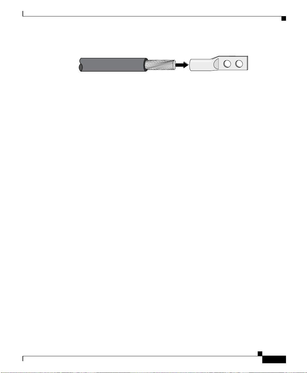
Chapter 2 Cabling the CSS
Figure 2-10 Attaching Grounding Wire to Grounding Lug
Connecting the Chassis to Ground
53632
Grounding lugStripped wire
Attach the grounding lug firmly to the threaded holes on the chassis using two
4.
M5 screws.
• On the CSS 11503 chassis, the holes are located on the left side (looking
from the rear) near the bottom rear corner.
• On the CSS 11506 cha ssis, th e h ol es ar e loca ted on the righ t rear pa nel .
The three threaded h ole s ar e u n evenly space d to accommodate different lugs.
5. Strip the covering from the other end of the grounding wire. See the table in
step 2 for strip l eng th s fo r di fferent lugs .
6. Insert the stripped end of the grounding wire into the open end of a grounding
lug and crimp the groundi ng lug secur ely to the w ire.
7. Attach the ground in g lu g to a n app rop ria te gro undin g point at your si te .
78-13884-03
8. Go to the next section, “Connecting the Power Cord”.
Cisco 11500 Series Content Services Switch Hardware Installation Guide
2-25
Page 82

Connecting the Power Cord
Connecting the Power Cord
The CSS 11500 series models are powered by eithe r a n AC or DC power supply.
Before you install the AC or DC power cord, ensur e that you have read
Appendix A, Specifications, for inform ation on the electr ical s pecif i cation s. The
following sections describe:
• Connecting a CSS 11501 Power Cord
• Connecting a CSS 11503 Power Cord
• Connecting a CSS 11506 Power Cord
• Checking the DC Power Connectio n (CSS 1 150 3 and CSS 11 506)
Connecting a CSS 11501 Power Cord
To connect an AC power cord to a CSS 11501:
1. At the rear of the chassis, ensure that the CSS power switch is in the O (off)
position.
Chapter2 Cabling the CSS
2-26
2. Plug the AC power cord connector into the CSS power connector, as shown
in Figure 2-11.
Figure 2-11 Connecting a CSS 11501 AC Power Cord
1
78677
2
1 AC power connector 2 Power switch
Cisco 11500 Series Content Services Switch Hardware Installation Guide
78-13884-03
Page 83

Chapter 2 Cabling the CSS
100-240V
~
50-60 Hz
5A
430 W
3. Plug the power cord into a dedicated 3-w ire grou nding rec eptacl e.
4. To power on and boot the CSS, ref er to Cha pter 3, Booting and Configuring
the CSS.
Connecting a CSS 11503 Power Cord
The following sections provide information on:
• Connecting a CSS 11503 AC Power Cord
• Connecting a CSS 11503 DC Power Cor d
Connecting a CSS 11503 AC Power Cord
To connect an AC power cord to a CSS 11503:
1. At the rear of the chassis, ensure that the CSS power switch is in the O (off)
position.
2. Plug the AC power cord connector into the CSS power connector, as shown
in Figure 2-12.
Connecting the Power Cord
78-13884-03
Figure 2-12 Connecting a CSS 11503 AC Power Cord
1
59543
2
1 Power switch 2 AC power connector
Cisco 11500 Series Content Services Switch Hardware Installation Guide
2-27
Page 84

Connecting the Power Cord
3. Plug the power cord into a dedicated 3-w ire grou nding rec eptacl e.
4. To power on and boot the CSS, ref er to Cha pter 3, Booting and Configuring
the CSS.
Connecting a CSS 11503 DC Power Cord
Before you install a D C power cord, re fer t o Ap pendi x A, Specifications, for the
DC power supply.
Chapter2 Cabling the CSS
Warning
Warning
Warning
Warning
Warning
The DC power supply cord requires at least a 14 AWG wire (maximum 10 AWG
wire). The CSS 11503 draws a maximum of 10 amps.
Use copper conductors only.
Before working on equipment that is connected to power lines, remove jewelry
(including rings, necklaces, and watches). Metal objects will heat up when
connected to power and ground and can cause serious burns or weld the metal
object to the terminals.
Before performing the DC installation procedure, ensure that power is removed
from the DC circuit. To ensure that all power is off, locate the circuit breaker
that services the DC circuit and switch it off.
When you are installing or replacing the unit, the ground connection must
always be made first and disconnected last.
2-28
Cisco 11500 Series Content Services Switch Hardware Installation Guide
78-13884-03
Page 85

Chapter 2 Cabling the CSS
Connecting the Power Cord
Warning
Only a DC power source that is isolated from AC mains with reinforced
insulation, and that complies with t he other s afety extra-low volt age (SELV)
requirements in UL1950, CSA 950 3rd Edition, EN 60950, and IEC950, can be
connected to a Cisco 11503 system. This requirement ensures that in a
catastrophic power source fault condition, hazardous voltages are not present
on power terminals and connectors.
To connect the CSS 115 03 DC power suppl y to a p ower sourc e:
1. At the rear of the chassis, ensure that the CSS power switch is in the O (off)
position.
2. Locate the DC terminal block on the rear of the chassis as shown in
Figure 2-13.
Figure 2-13 Location of the CSS 11503 DC Power Supply Connectors
-48/-60V
9.0A,430VA
78-13884-03
59544
1 2
1 Terminal block (–, +, and ) 2 Power switch
Cisco 11500 Series Content Services Switch Hardware Installation Guide
2-29
Page 86

Connecting the Power Cord
Chapter2 Cabling the CSS
3. Using a flat-head screwdriver, loosen the captive screws on the three DC
connectors (labeled from left to right, –, +, and , resp ec t ively).
Warning
Warning
Before installing a wire, ensure that the polarity of the DC connections is
correct. Reversed polarity causes damage to the DC power supply and can
create a dangerous shock hazard.
Do not consolidate the end of a conductor by soft soldering prior to installation.
4. Install the wire s in to the ap pro priat e conne ctor. Make sure th at the
non-insulated par t of e ach wi re i s 9 m m (0. 35 inc he s) in l engt h.
When installing the wires, always connect the ground wire first. When
disconnecting the wires, always disconnect the ground wire last.
5. Tighten the captive screws to 5 to 7 inch-pounds (0.6 to 0.8 Nm) of torque to
secure the wires in the connectors. Ensure that the wires are held firmly in
place.
6. Install the wires to the DC power source.
For the proper power cable wiring between t he CSS 11503 and DC power
source, see Table 2-9.
Table 2-9 CSS 11503 to DC Power Source Cabling
CSS 11503 DC Power Source
(Ground)
(Ground)
++
––
2-30
Warning
The proper wiring sequence is ground to ground, positive to positive, and
negative to negative. The ground wire should always be connected first and
disconnected last.
Cisco 11500 Series Content Services Switch Hardware Installation Guide
78-13884-03
Page 87

Chapter 2 Cabling the CSS
7. Switch on the circuit breaker that services the DC circuit.
8. T o check th e DC po wer connec tion, see “Checking the DC Power Connection
(CSS 11503 and CSS 11506)”.
Connecting a CSS 11506 Power Cord
The following sections provide information for connecting an AC or DC power
cords to a CSS 11506.
• Connecting a CSS 11506 AC Power Cord
• Connecting a CSS 11506 DC Power Cor d
Connecting a CSS 11506 AC Power Cord
To connect the AC power cord to each power supply in the CSS 11506:
1. At the front of the supply, ensure that the CSS power switch is in the O (off)
position.
Connecting the Power Cord
78-13884-03
2. Plug the AC power cord connec tor int o t he power conn ec tor, as shown in
Figure 2-14.
Cisco 11500 Series Content Services Switch Hardware Installation Guide
2-31
Page 88

Connecting the Power Cord
C
S
S
5
-1
0
M
-2
G
E
G
ig
a
b
it E
th
e
rn
e
t
G
E
1
G
E
2
L
IN
K
L
IN
K
1
2
4
3
C
S
S
5
-1
0
M
-1
6
F
E
1
2
3
4
5
6
PS
1
PS
2
PS
3
7
D
IS
C
O
N
NE
C
T
A
LL
P
O
W
ER
SO
U
R
C
ES
B
E
FO
R
E
S
E
R
VIC
IN
G
C
A
U
TIO
N
8
100-240V
~
5A 50-60 H
z
AC
O
K
D
C
O
K
AC
O
K
D
C
O
K
100-240V
~
5A 50-60 H
z
A
C
O
K
DC
O
K
C
S
S
5
-1
0
M
-2
G
E
G
ig
a
b
it E
th
e
rn
e
t
G
E
1
G
E
2
L
IN
K
L
IN
K
1
2
4
3
C
S
S
5
-1
0
M
-1
6
F
E
1
2
3
4
5
6
PS
1
PS
2
PS
3
7
D
IS
C
O
N
NE
C
T
A
LL
P
O
W
ER
SO
U
R
C
ES
B
E
FO
R
E
S
E
R
VIC
IN
G
C
A
U
TIO
N
8
100-240V
~
5A 50-60 H
z
AC
O
K
D
C
O
K
AC
O
K
D
C
O
K
100-240V
~
5A 50-60 H
z
A
C
O
K
DC
O
K
Figure 2-14 Connecting a CSS 11506 AC Power Cord
1 Power supply LEDs 3 AC power connector
2 Power switch
Chapter2 Cabling the CSS
1
1
2
2
59545
59545
3
3
3.
Plug the power cord into a dedicated 3-w ire grou nding rec eptacl e.
4. Repeat steps 1 through 3 for each power supply.
5. To power on and boot the CSS, ref er to Cha pter 3, Booting and Configuring
the CSS.
Cisco 11500 Series Content Services Switch Hardware Installation Guide
2-32
78-13884-03
Page 89

Chapter 2 Cabling the CSS
Connecting a CSS 11506 DC Power Cord
Before you install a D C power cord, re fer t o Ap pendi x A, Specifications, for the
DC power supply.
Connecting the Power Cord
Warning
Warning
Warning
Warning
Warning
The DC power supply cord requires at least a 14 AWG wire (maximum 10 AWG
wire). The CSS 11503 draws a maximum of 18 amps.
Use copper conductors only.
Before working on equipment that is connected to power lines, remove jewelry
(including rings, necklaces, and watches). Metal objects will heat up when
connected to power and ground and can cause serious burns or weld the metal
object to the terminals.
Before performing the DC installation procedure, ensure that power is removed
from the DC circuit. To ensure that all power is off, locate the circuit breaker
that services the DC circuit and switch it off.
When you are installing or replacing the unit, the ground connection must
always be made first and disconnected last.
78-13884-03
Cisco 11500 Series Content Services Switch Hardware Installation Guide
2-33
Page 90

Connecting the Power Cord
C
S
S
5
-1
0
M
-2
G
E
G
ig
a
b
it E
th
e
rn
e
t
G
E
1
G
E
2
L
IN
K
L
IN
K
1
2
3
C
S
S
5
-1
0
M
-1
6
F
E
1
2
3
4
5
6
P
S1
PS2
P
S3
7
D
ISC
O
N
N
ECT A
LL
PO
W
E
R
SO
U
RC
ES
B
EFO
R
E SERVIC
IN
G
C
A
U
TIO
N
8
100-240V
~
5A 50-60 Hz
AC
O
K
DC
O
K
-48/-60V
10/8A
I/P
OK
DC
OK
A
C
O
K
D
C
O
K
59199
Chapter2 Cabling the CSS
Warning
Warning
Only a DC power source that is isolated from AC mains with reinforced
insulation, and that complies with t he other s afety extra-low volt age (SELV)
requirements in UL1950, CSA 950 3rd Edition, EN 60950, and IEC950, can be
connected to a Cisco 11506 system. This requirement ensures that in a
catastrophic power source fault condition, hazardous voltages are not present
on power terminals and connectors.
This unit might have more than one power supply connection; all connections
must be removed completely for you to completely remove power from the unit.
To connect each CSS 11506 DC power supply to a power source:
1. On the power supply, ensure that the CSS power switch is in the O (off)
position.
2. Locate the power sup ply DC te rm inal bl ock, a s sh own in Fi gure 2-15.
Figure 2-15 Location of CSS 11506 DC Power Supply Connectors
1 2
3
Cisco 11500 Series Content Services Switch Hardware Installation Guide
2-34
59546
1 Power supply LEDs 3 Terminal block (–, +, and )
2 Power switch
78-13884-03
Page 91

Chapter 2 Cabling the CSS
9199
Connecting the Power Cord
3. Using a flat-head screwdriver, loosen the captive screws on the three DC
connectors (labeled from left to right, –, +, and , respectively).
Warning
Warning
Before installing a wire, ensure that the polarity of the DC connections is
correct. Reversed polarity can cause damage to the DC power supply and can
create a dangerous shock hazard.
Do not consolidate the end of a conductor by soft soldering prior to installation.
4. Install the wire s in to the ap pro priat e conne ctor. Make sure th at the
non-insulated par t of e ach wi re i s 9 m m (0. 35 inc he s) in l engt h.
When installing the wires, always connect the ground wire first. When
disconnecting the wires, always disconnect the ground wire last.
5. Tighten the captive screws to 5 to 7 inch-pounds (0.6 to 0.8 Nm) of torque to
secure the wires in the connectors. Ensure that the wires are held firmly in
place.
6. Repeat steps 1 through 5 for each power supply.
7. Install the three sets of wires to the DC power source.
For the proper power cable wiring between t he CSS 11506 and DC power
source, see Table 2-10.
Table 2-10 CSS 11506 to DC Power Source Cabling
CSS 11506 DC Power Source
(Ground)
(Ground)
++
––
78-13884-03
Warning
The proper wiring sequence is ground to ground, positive to positive, and
negative to negative. The ground wire should always be connected first and
disconnected last.
Cisco 11500 Series Content Services Switch Hardware Installation Guide
2-35
Page 92

Chapter2 Cabling the CSS
Connecting the Power Cord
8. Switch on each circuit breaker that services each DC circuit.
9. To check the DC power connection, see the following section.
Checking the DC Pow er Co nn ectio n (CSS 115 03 and C SS 1 1506 )
Follow these steps to verify that you have correctly connected DC power to the
CSS 11503 or CSS 11506 chassi s:
1. Turn on power to the DC circuit or circuits.
2. Use a voltmeter to check the voltage at the terminal block on the power
supply. Connect the voltmeter’s positive contact to the positive (+) terminal
on the CSS power supply terminal block. Connec t the voltmeter ’s negative
contact to the neg ative (–) terminal on the CSS power supply terminal block.
If the power is wired correctly, the voltmeter registers approximately
+48VDC to +56VDC (or battery float voltage).
2-36
Warning
Do not allow the test probes of the voltmeter to touch each other while they are
touching the power terminals. This is an ENERGY HAZARD to you, to the
voltmeter, and to the wires connecting the CSS to its power source.
3. To power on and boot the CSS, ref er to Cha pter 3, Booting and Configuring
the CSS.
Cisco 11500 Series Content Services Switch Hardware Installation Guide
78-13884-03
Page 93

CHAPTER
3
Booting and Configuring the CSS
This chapter descri b es how to bo ot t h e CSS a nd usin g th e co nfigurati on sc ript s.
This chapter contains the following sections:
• Powering Up the CSS
• Powering Down the CSS
• Booting the CSS for the First Time
• Logging in to the CSS
• Using the Configuration Script
For more information on failur e errors an d messag es that can occur duri ng the
boot process, refe r to A ppend ix C, Troubleshooting.
Powering Up the CSS
To power up a CSS:
• On an AC CSS, toggle the power switch to the 1 (on) position.
–
See Figure 2-11 for the location of the CSS 11501 AC power switch.
–
See Figure 2-12 for the location of the CSS 11503 AC power switch.
–
See Figure 2-14 for the location of th e CSS 115 06 AC power switch for
each power supply. Power on all of the supplies in the CSS. The AC OK
and DC OK LEDs light up on each power supply. If either LED rema ins
unlit, refer to Appendix C, Troubleshooting.
Cisco 11500 Series Content Services Switch Hardware Installation Guide
78-13884-03
3-1
Page 94

Powering Down the CSS
• For a DC CSS, switch on the applicable circuit breakers for the power source.
Then on the CSS, toggle the power switch to the 1 (on) position.
–
See Figure 2-13 for the location of the CSS 11503 DC power switch.
–
See Figure 2-15 for the location of the CSS 115 06 DC power switch fo r
each power supply. Power on all of the supplies in the CSS. The I/P OK
and DC OK LEDs light up on each power supply. If either LED rema ins
unlit, refer to Appendix C, Troubleshooting.
The CSS starts the boot process. Proceed to “Booting the CSS for the First Time”.
Powering Down the CSS
To shut down the CSS grac eful ly and avoid introd ucin g lost or f ragme nte d files,
always use the shutdown command prio r to removing power fro m the CSS.
For example:
(config-boot)# shutdown
Once the CSS shuts down all processes, you can remove power from the CSS.
Chapter 3 Booting and Configuring the CSS
Booting the CSS for the First Time
When the CSS initially boots up, it:
• Performs hardware diagnostic s.
• Prompts you to:
–
Enter the software license key
–
Configure the IP address, subnet mask, and default gateway for the
Ethernet Management port, used for CSS configuration and management
only; this port does not route traffic
–
Change the default admini strative login name (admin) a nd password
(
system)
–
Password-protect the Offline Diagnostic Monitor (OffDM) menu
Cisco 11500 Series Content Services Switch Hardware Installation Guide
3-2
78-13884-03
Page 95

Chapter 3 Booting and Configuring the CSS
Booting the CSS for the First Time
Note When you initially boot a CSS with two PCMCIA disk drives, the drive in slot 0
contains the directorie s f or th e sy stem so ftwa re a nd the log files. Af ter yo u log in
to the CSS, you c an c on figure the drive in slot 1 f or use t hroug h the map
commands, as d esc ribe d i n th e Cisco Content Services Switch Administration
Guide.
Hardware Initialization and Power-On Diagnostics
When you boot the CSS, it initializes the hardware and performs power-on
diagnostics. The CSS displays the following messages (shown for the CSS 11503
and CSS 11506):
Locked boot flash.
Validating operational boot flash, please wait...
Operational boot flash valid. Jumping to operational boot flash.
Copyright 2002(c), Cisco Systems, Inc.
Operational boot flash.
Attaching interrupt handlers...Done.
Master SCM.
Built Jun 22 2002 @ 15:14:20
Version x.xx Build xx
78-13884-03
Then the hardware goes through a series of tests by the Diagnostic Monitor. These
tests perform power-on self tests on the CSS 11501 components, or on the
CSS 11506 or CSS 11506 m odu les, c hassi s, a nd back plan e. The a steri sks that
appear indicate the completion of each test.
Press <ESC> to enter the Diagnostic Monitor
* * * * * * * * * * * * * *...
Ran 1 times, x tests. Detected 0 errors.
During this time, the Status LEDs on the CSS 11501 or on each CSS 11503 or
CSS 11506 module blink and ch ange color to indic ate the stage s of the boot
process. The left Sta tus LED is bic olo r, green or red. Th e righ t St atu s L ED is
amber.
Note The Ethe rnet co nnecto rs on the CSS 115 01 and the 8- and 16- port Fast Ether net
Modules on the CSS 11503 or CSS 11506 do not have Status LEDs. They have
Link and Duplex LEDs that indicate the state of the connection.
Cisco 11500 Series Content Services Switch Hardware Installation Guide
3-3
Page 96

Booting the CSS for the First Time
Table 3-1 defines the boot stat es a nd the St atu s LED s blinki n g patt erns.
Table 3-1 Status LEDs Boot Definitions
State Sequence LED Color LED State
1. Power up, flash sca n, a nd power-on self test
occur.
Power-on self test detects an error. Red Solid
2. The CSS 11501 or a module in the CSS 11503 or
CSS 11506 is off line and active.
3. The CSS 1150 or a mod ule in the CSS 1150 3 or
CSS 11506 module is on line and not active.
In the CSS 11506, a p assive SCM LED rem ains
in this state and color.
4. The CSS 11501 or a module in the CSS 11503 or
CSS 11506 is on line and active.
The CSS 11501 or a module in the CSS 11503 or
CSS 11506 (except a Fast Ether net Modu le)
fails.
Chapter 3 Booting and Configuring the CSS
Amber Fast blink
Amber Slow blink
Amber Solid
Green Solid
Red Blinking
3-4
If a Fast Ethernet Module fails in the CSS 11503
or CSS 11506, all of its Link an d Duplex LEDs
blink simultaneously.
In the CSS 11503 or CSS 11506, when the
master SCM in slot 1 detects a module failure, its
Status LED is green and blinks slowly.
When the master SCM in slot 1 fails, the CSS
does not boot unless the re is a passive SCM in
slot 2.
5. Disk activity Green Variable
blinking
If an error occurs during a test, the console displays an error message, increments
the detected error counter, and continues to the next test until it completes all of
the power-on self tests. For more information on error s and m essages, refe r to
Appendix C, Troubleshooting.
Cisco 11500 Series Content Services Switch Hardware Installation Guide
78-13884-03
Page 97

Chapter 3 Booting and Configuring the CSS
Note For information on c onfiguring the passive SCM in a CSS 11503 or CSS 11506,
refer to the Cisco Content Services Switch Administration Guide.
Entering Your License Key
When the CSS completes hardware ini tializat ion and power-on diagnostic s, you
must enter a valid license key for the CSS software. The CSS does not require you
to enter this key on sub s eque nt st art ups .
Note Y our license key is located on a white label printed with the “S11K-” product code
and is found inside the CSS accessory kit. If you cannot find the software license
key, call the Cisco Technical Assistance Center (TAC) toll free, 24 hours a day, 7
days a week at 1-800-553 -2447 or 1-408 -526-7 209. You can also email TAC at
tac@cisco.com.
The CSS prompts you to accept the license agreement. You must accept the
license agreement or you cannot l og into the CSS.
Booting the CSS for the First Time
78-13884-03
Then the CSS prom pts y ou to e nte r you r lic en se key, as shown below:
Enter Software License Key: xxxxxxxxxxxx
When you enter:
• A valid license number, the CSS pr ompt s yo u to ent er a n IP ad dre ss for the
Ethernet Managem ent port.
• An invalid license number, the CSS redisplays the license prompt until you
enter a valid numbe r. If you do not en te r a valid li cense n umb er, you can not
log in to the CSS.
Cisco 11500 Series Content Services Switch Hardware Installation Guide
3-5
Page 98

Chapter 3 Booting and Configuring the CSS
Booting the CSS for the First Time
Note If you purcha sed the SSH software option (as part of the Secure Manag ement
option) or the Network Proximity software option, the license key is on the CSS
software license key card. After the CSS has booted and you log in, use the license
command to enter the license key. For example, enter:
#
license
Enter Software License Key (q to quit):
At the prompt, enter the 12-digit option license key.
Configuring the Ethernet Management Port
Once you enter a valid license key at the boot prom pt, the CSS di splays t he
following message and prompt:
Use the Ethernet management port IP address to access the Content
Services Switch for configuration and management only. This port does
not route traffic and is not associated with VLAN circuits.
3-6
The current address setting (0.0.0.0) disables the Ethernet Management
port.
Do you wish to configure a valid address for the Ethernet management
port [y/n]?
Cisco 11500 Series Content Services Switch Hardware Installation Guide
78-13884-03
Page 99

Chapter 3 Booting and Configuring the CSS
Enter:
• y to configure an IP address, subnet mask, and default gateway for the
Ethernet Management port. The CSS prompts you for an IP address, a subnet
mask, then a default gateway. You must enter a valid IP address or the CSS
repeats the prompt until you do. The CSS does not accept an all zero IP
address.
Note The Ethernet Mana gemen t port IP addr ess must be on a di fferent
subnet from any other CSS VLAN circuit subnet. If you do not make
this IP address un ique , you w il l no t be abl e t o acc ess the port .
Enter IP Address [0.0.0.0]:
Enter Subnet Mask [0.0.0.0]:
Enter Default Gateway [0.0.0.0]:
• n to accept the default IP ad dress (0.0. 0.0), su bnet mask (0. 0.0.0), an d default
gateway (0.0.0.0) and disa ble the p ort . T he CSS doe s not pro mpt you for an
IP address, subnet mask, and default gateway.
Booting the CSS for the First Time
Note The Ethe rnet M anagem ent port defau lt IP address of 0. 0.0.0 disa bles the
Management port . To enable the Ethern et M a nage ment p ort, u se the O ffline
Diagnostic Monitor (Offline DM) menu or specify the ip address command in
boot mode. Refer to the Cisco Content Services Switch Administration Guide for
details on setting the Ethernet Management port IP address.
Changing the Default Username and Password
The CSS allows you to change the default username and password.
Access to this device is allowed using the default username and
password. For enhanced security we recommend that you change the
defaults. Do you want to change the defaults now (yes,no):
Cisco 11500 Series Content Services Switch Hardware Installation Guide
78-13884-03
3-7
Page 100

Chapter 3 Booting and Configuring the CSS
Booting the CSS for the First Time
Enter:
• yes to cha nge t he use rnam e an d p ass word. The CSS prom pts y ou fo r th is
information and password con firmation.
Enter <administrator> username:
Enter <administrator> password:
Confirm <administrator> password:
• no to keep the default username and password.
Password-Protecting the Offline Diagnostic Monitor Menu
The CSS prompts you to password-prote ct the Offline Diagno stic Moni tor
(OffDM) menu.
Set Password Protection for Offline Diagnostic Monitor menu (yes,no)
Caution Use care wh en pa sswo rd- pro t ect ing th e O ffDM Ma i n m en u an d ens u re t ha t y ou
write down the new password. If you lose the new password, it cannot be
recovered and you will be unable to access the OffDM Main menu. The only
solution, at that point, would be to contact the Cisco Technical Assistanc e Center
(TAC) at 1-800-553-2447 or 1-408-526-7 209. You can also email TAC at
tac@cisco.com.
3-8
Enter:
• yes to password- pro tec t the OffDM menu . When you pa ssword-p ro tect the
OffDM menu, you need to e nte r the admi nis trative user name and pa ssword
each time you access the menu.
The administrative username and password are required to access
the Offline Diagnostic Monitor menu.
Initializing the disk...........OK
For information on t he Of fline Diagnostic Monitor Menu options, re fer to the
Cisco Content Services Switch Administration Guide, Chapter 1, Logging In
and Getting Started.
• no to disable password-protection on the OffDM menu.
Cisco 11500 Series Content Services Switch Hardware Installation Guide
78-13884-03
 Loading...