

Page 1

CHA PTER
5
Managing Modules
This chapter describes the management tasks that can be performed on the modules in the
Cisco 12000/10720 internet router being managed using the Cisco 12000/10720 Router Manager
application.
The following modules can be managed using the Cisco 12000/10720 Router Manager:
• GRPs
• Line cards—ATM, Ethernet, SRP, POS, DS-3, Fast Ethernet and Gigabit Ethernet
• Supporting modules—CSCs, SFCs, AC or DC power supply modules, fan tray modules, blower
modules, alarm modules and bus board
This chapter contains the following sections:
• Cisco 12000/10720 Router Manager Module Names
• Launching the Module Management Windows
• Module Configuration
• Module Fault Management
• Module Performance (only available on GRPs)
• Module Inventory
Cisco 12000/10720 Router Manager Module Names
The naming convention used in Cisco 12000/10720 Router Manager for line cards, GRPs, CSCs, and
SFCs is an abbreviated form of the type of module, followed by the slot number of the module. For
example, an ATM line card in slot 6 is called A6, and a POS line card in slot 3 is called P3.
Table 5-1 identifies each module type and its respective abbreviation in Cisco 12000/10720 Router
Manager.
Table 5-1 Abbreviated Module Names
Cisco 12000/10720 Router Manager
Module
DS-3 D
POS P
AT M A
Abbreviation
OL-3865-01
Cisco 12000/10700 v3.1 Router Manager User Guide
5-1
Page 2
Launching the Module Management Windows
Table 5-1 Abbreviated Module Names (continued)
Module
Fast Ethernet FE
Gigabit Ethernet GE
SRP S
Unrecognized Modules* GM (Generic Module)
GRP RP
CSC C
SFC SF
Lower Blower LBM
Upper Blower UBM
Power Supply PSM
Alarm ALR
Chapter 5 Managing Modules
Cisco 12000/10720 Router Manager
Abbreviation
*Note that basic module management services are provided for any non-standard Cisco 12000/10720 Router Manager modules.
Launching the Module Management Windows
Table 5-2 displays the Module Management windows that can be launched from each object type. For
example, the Module Fault Management window can be launched from a Site, Chassis or Module object,
but cannot be launched from an Interface object.
Note Table 5-2 lists the menu options to launch the module management dialogs from the site level.
Table 5-2 Launching the Module Management Windows
Cisco 12000/10720 Router
Manager Window/Task
Module Configuration Yes Yes Yes Yes No Cisco 12000/10720 Manager>Configuration>
Module Fault Management Yes Yes Yes Yes No Cisco 12000/10720 Manager>Fault>Module>
Module Performance Yes Yes Yes No No Cisco 12000/10720 Manager>Performance>
Module Inventory Yes Yes Yes Yes No Cisco 12000/10720 Manager>Accounting>
Objects to Select to Open the Window
Site Chassis Module Interface
12000
10720
series
Menu Options to Select to Open Window
Module >Configuration
Fault Management
Module> Performance
Module>Inventory
5-2
Cisco 12000/10700 v3.1 Router Manager User Guide
OL-3865-01
Page 3

Chapter 5 Managing Modules
Note Cisco 12000/10720 Router Manager windows cannot be opened when multiple objects are
selected (the menu options to open the Cisco 12000/10720 Router Manager windows are
grayed out). Available menu options can be launched from a site object containing the
required objects, when needed.
Module Configuration
The Configuration window allows you to commission or decommission any module. You can also
provide text descriptions of the specific module, if required.
The Module Configuration section provides the following information:
• Viewing the Configuration Window
• Commissioning a Selected Module
• Decommissioning a Selected Module
• Module Configuration Window—Detailed Description
Module Configuration
Viewing the Configuration Window
To view the Configuration window, proceed as follows:
Step 1 Right click on a module and select the Cisco 12000/10720 Manager>Configuration>Module
Configuration option. Refer to Table 5-2 on page 5-2 for information on which objects allow you to
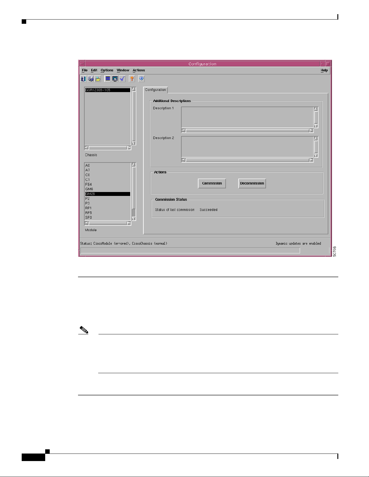
launch the Configuration window. The Configuration window appears with the Configuration tab
displayed:
OL-3865-01
Cisco 12000/10700 v3.1 Router Manager User Guide
5-3
Page 4
Module Configuration
Chapter 5 Managing Modules
Figure 5-1 Configuration Window
Step 2 Choose a Chassis and Module from the list boxes displayed at the left of the window.
Commissioning a Selected Module
Commissioning any card also commissions all the interfaces under the card.
Note You can select multiple Modules (from the Module object selector list) which allows you to
commission all of the selected modules simultaneously. You can choose multiple modules in a
list by holding down the Shift key and then selecting the first and last module in the list. You can
choose multiple individual modules by holding down the Ctrl key and clicking on the individual
modules.
To commission a module, proceed as follows:
Step 1 Open the Configuration window. Refer to the “Viewing the Configuration Window” section on page 5-3
for further details.
Step 2 Choose a Chassis and Module from the list boxes displayed at the left of the window.
5-4
Cisco 12000/10700 v3.1 Router Manager User Guide
OL-3865-01
Page 5
Chapter 5 Managing Modules
Step 3 Enter additional descriptions into the Description 1 and Description 2 fields in the Additional
Descriptions area (if required). Entering additional descriptions is optional.
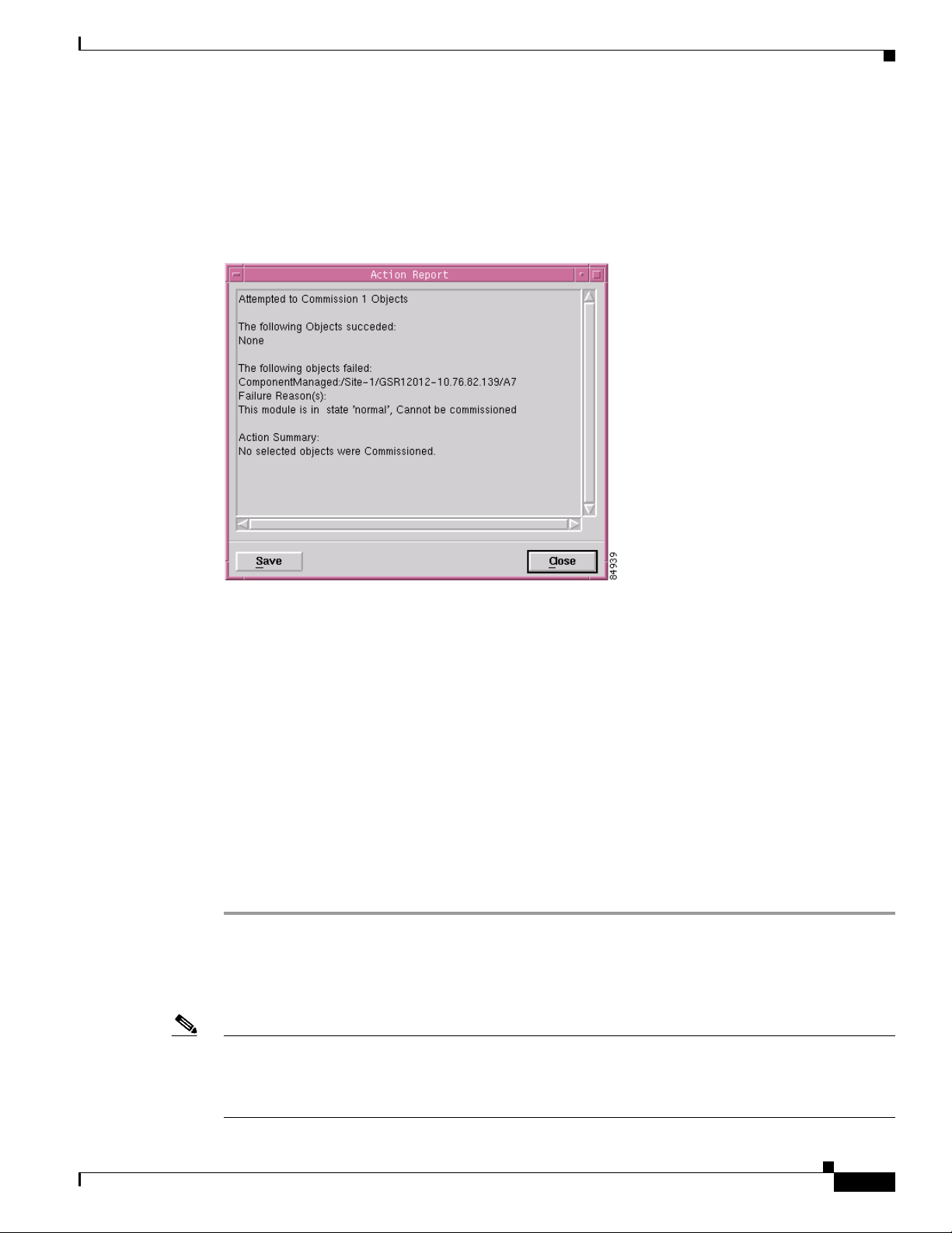
Step 4 Choose Commission to commission the selected module. An Action Report window appears confirming
that the commissioning action was completed successfully.
Figure 5-2 Action Report Window
Module Configuration
Step 5
Choose Close to close the Action Report window.
The selected module is now commissioned. Commissioning a GRP or any supporting module initiates
the following activities:
• Heartbeat polling begins on the object
• The state is changed to normal
• Status data becomes available
Commissioning a line card initiates the following activities:
• All interfaces on the line card are also commissioned
• Heartbeat polling begins on the line card and interfaces
• The line card and active interfaces are placed in the normal state
• Any interfaces that are pre-deployed but not active change to the errored state
• Status data becomes available on the line card and interfaces
Decommissioning a Selected Module
Note You can select multiple Modules from the Module object selector list. Selecting multiple modules allows
you to decommission all of the selected modules simultaneously. You can choose multiple modules in a
list by holding down the Shift key and then selecting the first and last module in the list. You can choose
multiple individual modules by holding down the Ctrl key and clicking on the individual modules.
OL-3865-01
Cisco 12000/10700 v3.1 Router Manager User Guide
5-5
Page 6
Module Configuration
Step 1 Open the Configuration window. Refer to the “Viewing the Configuration Window” section on page 5-3
Step 2 Choose a Chassis and Module from the list boxes displayed at the left of the window.
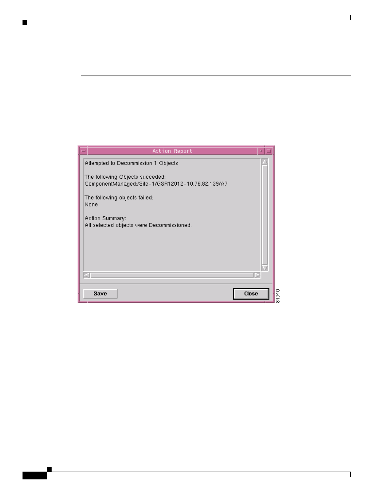
Step 3 Choose Decommission to decommission the selected module. An Action Report window appears
Chapter 5 Managing Modules
Decommissioning a GRP card also decommissions all interfaces under that GRP card.
To decommission a module, proceed as follows:
for further details.
confirming that the decommissioning action was completed successfully.
Figure 5-3 Action Report Window
5-6
Step 4
Choose Close to close the Action Report window.
The selected module is now decommissioned. Decommissioning a GRP or any supporting module
initiates the following activities:
• Heartbeat polling stops on the object
• The state is changed to decommissioned
• Status data is no longer available
• Performance polling stops on the module (if enabled)
Decommissioning a line card initiates the following activities:
• All interfaces and ATM connections on the line card are also decommissioned
• Heartbeat polling stops on the line card and interfaces
• The line card, interfaces, and ATM connections are placed in the decommissioned state
• Status data is no longer available on the line card and interfaces
Cisco 12000/10700 v3.1 Router Manager User Guide
OL-3865-01
Page 7

Chapter 5 Managing Modules
• Performance polling stops on the line card and interfaces (if enabled)
Module Configuration Window—Detailed Description
The Module Configuration window displays a single Configuration tab.
Configuration Tab
The Configuration tab (see Figure 5-1 on page 5-4) displays three areas: Additional Descriptions
Actions, and Commission Status.
Additional Descriptions
The Descriptions 1 and Descriptions 2 fields (optional) allow you to specify additional description
information for the selected module (if required).
Module Configuration
Actions
Commission Status
The Actions area contains two buttons:
Commission—Commissions the selected module.
Decommission—Decommissions the selected module.
The Commission Status area displays the status of the last commission performed on the selected
module. Possible values are Succeeded or Failed.
OL-3865-01
Cisco 12000/10700 v3.1 Router Manager User Guide
5-7
Page 8

Module Fault Management
Module Fault Management
The Module Fault Management window is a read-only window and provides fault information for a
selected module. You do not need to enter any information into any of the fields. This section provides
the following information:
• Viewing the Module Fault Management Window
• Module Fault Management Window—Detailed Description
Viewing the Module Fault Management Window
To view the Module Fault Management window, proceed as follows:
Step 1 Right click on a module and select the Cisco 12000/10720 Manager>Fault>Module Fault
Management option. Refer to Table 5-2 on page 5-2 for information on which objects allow you to
launch the Module Fault Management window. The Module Fault Management window appears, with
the Fault Management tab displayed:
Chapter 5 Managing Modules
Figure 5-4 Module Fault Management Window
5-8
Step 2
Cisco 12000/10700 v3.1 Router Manager User Guide
Choose a Chassis and Module from the list boxes at the left of the window. The fault management
information for the selected module appears. For detailed information on the areas within this tab, refer
to the “Module Fault Management Window—Detailed Description” section on page 5-9.
OL-3865-01
Page 9

Chapter 5 Managing Modules
Module Fault Management Window—Detailed Description
The Module Fault Management window displays a single Fault Management tab. The Fault Management
tab displays two areas: Module Availability and Cisco Contact Details.
Note The details related to the modules are available only if the module is in a managed state.
Module Availability
The Module Availability area contains the following fields:
• Up Time—Displays the time after the network portion of the system was last re-initialized for the
selected module.
• Free Memory—Displays the memory space (in bytes) currently unused by the selected GRP module.
• Last Restart Reason—Displays the reason for the system being re-initiated for the selected GRP
module.
• Last Authentication Failure Address—Displays the last authorization failure IP address for the
selected module.
• Operational Status—Displays the current operational status of the selected GRP module. Possible
values are:
Module Performance
–
Up—Module is recognized by the device and is operational.
–
Down—Module is not recognized by the device or not enabled for operation.
–
Standby—Module is enabled and is acting as standby. This value is only applicable for
redundant GRPs.
Cisco Contact Details
The Cisco Contact Details area provides Cisco contact details.
Module Performance
The Module Performance window displays the current performance information for the selected GRP
module.
Note You can select multiple Modules from the Module object selector list. Selecting multiple modules allows
you to start or stop performance logging for all of the selected modules simultaneously. You can choose
multiple modules in a list by holding down the Shift key and then selecting the first and last module in
the list. You can choose multiple individual modules by holding down the Ctrl key and clicking on the
individual modules.
The Module Performance tab displays CPU Usage information and allows you to Start or Stop
performance logging for one or more selected modules.
OL-3865-01
Cisco 12000/10700 v3.1 Router Manager User Guide
5-9
Page 10

Module Performance
Note Performance logging can also be started on a per module (GRP) or physical interface basis. For details
on how to start performance logging for a selected module (GRP), refer to the “Module Performance”
section on page 5-9. For details on how to start performance logging for a selected physical interface
(such as Ethernet, ATM, or DS-3), refer to the “Starting Performance Logging for a Selected Interface”
section on page 10-6.
Selecting a module provides performance data for the selected module. The values displayed relate to
CPU performance, so modules without a CPU display the same value as the CPU card in the chassis.
The Module Performance section provides the following information:
• Viewing the Module Performance Window
• Starting or Stopping Performance Logging
• Module Performance Window—Detailed Description
Viewing the Module Performance Window
Chapter 5 Managing Modules
Note The Module performance window can be launched from the chassis level. Please note that this window
cannot be launched from the module level.
To view the Module Performance window, proceed as follows:
Step 1 Right click on the chassis object and select the Performance>Module>Performance option. Refer to
Table 5-2 on page 5-2 for information on which objects allow you to launch the Module Performance
window. The Module Performance window appears, with the Performance tab displayed:
5-10
Cisco 12000/10700 v3.1 Router Manager User Guide
OL-3865-01
Page 11

Chapter 5 Managing Modules
Figure 5-5 Module Performance Window
Module Performance
Step 2
Choose a Chassis and Module(s) from the list boxes displayed at the left of the window. The
performance information for the selected GRP module is displayed.
Starting or Stopping Performance Logging
Performance logging allows performance information to be collected for a selected module. This
historical information can then be viewed using the Cisco EMF Performance Manager application.
Chapter 20, “Performance Management and Historical Data,” provides further information on how to use
the Performance Manager application.
To Start/Stop performance logging for a selected module, proceed as follows:
Step 1 Open the Module Performance window. Refer to the “Viewing the Module Performance Window”
section on page 5-10 for further details.
Step 2 Choose a Chassis and Module(s) from the list boxes displayed at the left of the window. The
performance information for the selected GRP module is displayed.
Note You can select multiple Modules from the Module object selector list. Selecting multiple
modules allows you to start/stop performance logging for all of the selected modules
simultaneously. You can choose multiple modules in a list by holding down the Shift key and
then selecting the first and last module in the list. You can choose multiple individual modules
by holding down the Ctrl key and clicking on the individual modules.
OL-3865-01
Cisco 12000/10700 v3.1 Router Manager User Guide
5-11
Page 12

Module Performance
Step 3 Click Start to begin performance logging for the selected module. Click Stop to stop performance
logging for the selected module.
Step 4 Launch the Performance Manager application to view the historical performance information for the
selected module. Refer to Chapter 20, “Performance Management and Historical Data,” for further
information on how to use the Performance Manager application.
Module Performance Window—Detailed Description
The Module Performance window (see Figure 5-5 on page 5-11) displays a single Performance tab. The
Performance tab has two areas: CPU Usage and Performance Logging.
CPU Usage
The CPU Usage area displays the following fields:
• CPU Busy%—Displays the percentage of CPU put to use for the selected GRP module.
Chapter 5 Managing Modules
• Average (1 min)—Displays the percentage of CPU being utilized averaged over a one minute period
• Average (5 min)—Displays the percentage of CPU being utilized averaged over five minute period
Performance Logging
The Performance Logging area allows you to start or stop performance logging.
• Start—Click Start to enable performance logging for the selected GRP module. Enabling
• Stop—Click Stop to stop all performance logging on the selected module. Disabling performance
for the selected GRP module.
for the selected GRP module.
performance logging allows performance data to be gathered for the selected module. Performance
polling occurs every 15 minutes. Performance data is then gathered and stored for historical review.
Current performance data can be viewed in the performance windows, or you can view historical
performance data in Performance Manager.
logging stops performance data from being gathered for the selected GRP module.
5-12
Cisco 12000/10700 v3.1 Router Manager User Guide
OL-3865-01
Page 13

Chapter 5 Managing Modules
Module Inventory
The Module Inventory section provides the following information:
• Viewing the Module Inventory Window
• Module Inventory Window—Detailed Description
Viewing the Module Inventory Window
To view the Module Inventory window for a selected module, proceed as follows:
Step 1 Right click on the module and select the Cisco 12000/10720 Manager>Accounting>Module Inventory
option. Refer to Table 5-2 on page 5-2 for information on which objects allow you to launch the Module
Inventory window. The Module Inventory window appears, with the General tab displayed:
Figure 5-6 Module Inventory Window
Module Inventory
OL-3865-01
Step 2
Not applicable for Cisco 12000/10720 Router Manager
Choose a Chassis and Module from the list boxes at the left of the window. The inventory information
for the selected module appears.
Cisco 12000/10700 v3.1 Router Manager User Guide
5-13
Page 14

Module Inventory
Note The Module Inventory window is read-only.
Module Inventory Window—Detailed Description
The Module Inventory window has two tabs: General and Asset Tracking. Only the General tab is
applicable to Cisco 12000/10720 Router Manager. The Asset Tracking tab is not applicable to Cisco
12000/10720 Router Manager.
General
The General tab (see Figure 5-5 on page 5-11) has four areas:
Module Details
Chapter 5 Managing Modules
System Details
Version Details
The Module Details area contains the following fields:
Serial Number—Displays the serial number of the selected module. This number is zero if data is
unavailable.
Description—Displays a description of the selected module.
Type—Displays the type of the selected module.
The System Details area contains the following fields:
Host Name—Displays the host name of the system which contains the selected module.
Boot Image Host—Displays the IP address of the host, which supplies the software currently running.
Description—Displays the hardware type, software operating system, and networking software of the
system that contains the selected module.
ROM ID—Displays the system boot strap description and version identifier.
Domain Name—Displays the domain portion of the domain name for the system which contains the
selected module.
Services—Displays all the services available on the system.
The Version Details area contains the following fields:
IOS—Displays the IOS operating software version being used by the selected module.
5-14
Hardware—Displays the version of the selected module.
Firmware—Not applicable to Cisco 12000/10720 Router Manager.
Software—Displays the software version installed in the card. No information appears if data is not
available.
Cisco 12000/10700 v3.1 Router Manager User Guide
OL-3865-01
Page 15

Chapter 5 Managing Modules
Slot & Ports
Asset Tracking
Module Inventory
The Slot & Ports area contains the following fields:
Slot Number—Slot position the module occupies in the chassis.
Max Supported Ports—Maximum number of ports supported on this module.
Sub Slot Number—Not applicable to Cisco 12000/10720 Router Manager.
Number of Working Ports—Not applicable to Cisco 12000/10720 Router Manager.
The Asset Tracking tab is not applicable to Cisco 12000/10720 Router Manager.
OL-3865-01
Cisco 12000/10700 v3.1 Router Manager User Guide
5-15
Page 16

Module Inventory
Chapter 5 Managing Modules
5-16
Cisco 12000/10700 v3.1 Router Manager User Guide
OL-3865-01
 Loading...