

Page 1

Contents
Cisco 10000 ESR
AC Power Entry Module Installation
This publication contains instructions for installing the AC Power Entry Module
(PEM) in the Cisco 10000 Edge Services Router (ESR). If you are not familiar
with the Cisco 10000 router, see the Cisco 10000 ESR System Description, and
the Cisco 10000 ESR Hardware Installation Guide for additional information.
The following sections are included in this configuration guide:
• Product Description, page 2
• Prerequisites and Preparation, page 3
• Installation Guidelines, page 4
• Adding or Replacing an AC PEM, page 5
• FCC Class A Compliance, page 20
• Cisco Connection Online, page 20
• Documentation CD-ROM, page 22
Corporate Headquarters: Cisco Systems, Inc., 170 West Tasman Drive, San Jose, CA 95134-1706 USA
Copyright © 2000. Cisco Systems, Inc. All rights reserved.
78-10832-01
Page 2
Product Description
Product Description
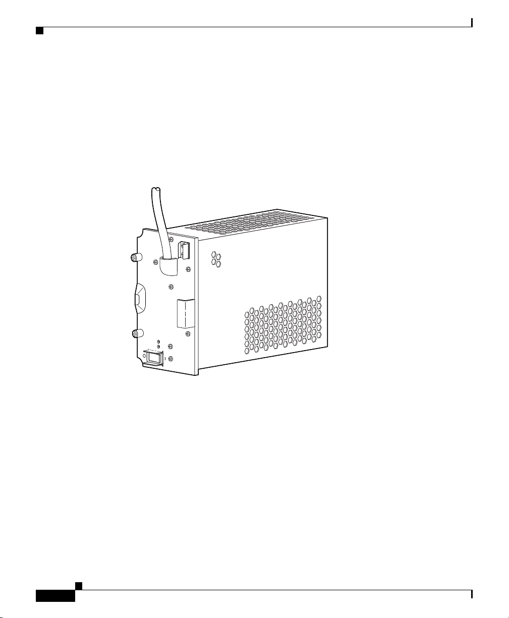
The AC PEM provides power conversion directly from the facility VAC input
power (100 VAC to 240 VAC) to the –48V VDC used internally by the system (see
Figure 1). AC power is delivered to the AC PEM from the VAC connection power
cable to the power cord attached to the PEM.
Figure 1 AC PEM
POWER
FAULT
30004
There are two PEM bays in the chassis; however, you only need one PEM to power
the router. You can install an additional PEM for power redundancy.
Cisco 10000 ESR AC Power Entry Module Installation
2
78-10832-01
Page 3

Prerequisites and Preparation
Before you perform any of the procedures in this guide, Cisco recommends that
you:
• Read the safety guidelines in the next section and review the electrical safety
and ESD-prevention guidelines in the Cisco 10000 ESR Hardware
Installation Guide.
• Ensure that you have all of the necessary tools and equipment before
beginning the installation (see the “Installation Guidelines” section on
page 4).
• Have access to the following documents (shipped with your Cisco 10000
system) during the installation:
–
Cisco 10000 ESR System Description
–
Cisco 10000 ESR Hardware Installation Guide
–
Cisco 10000 ESR Troubleshooting Guide
–
Cisco 10000 ESR Software Configuration Guide
Prerequisites and Preparation
Safety Guidelines
Before you begin the installation or replacement procedure, review the safety
guidelines in this section to avoid injuring yourself or damaging the equipment.
Before you install, configure, or perform maintenance on the router, you should
also review the safety warnings listed in the Cisco 10000 ESR Hardware
Installation Guide.
Safety Warnings
Safety warnings appear throughout this publication in procedures that, if
performed incorrectly, may harm you. A warning symbol precedes each warning
statement. The following warning is an example of a safety warning. It identifies
the warning symbol and associates it with a bodily injury hazard.
78-10832-01
Cisco 10000 ESR AC Power Entry Module Installation
3
Page 4

Installation Guidelines
Warning
Note If you need translations of the safety warning, see the Cisco 10000
This warning symbol means danger. You are in a situation that
could cause bodily injury. Before you work on any equipment, be
aware of the hazards involved with electrical circuitry and be
familiar with standard practices for preventing accidents. To see
translations of the warnings that appear in this publication, refer
to the Regulatory Compliance and Safety Information document
that accompanied this device.
ESR Hardware Installation Guide.
Installation Guidelines
The Cisco 10000 system is hot-swappable, which means you can remove and
replace a defective PEM while the system is operating (assuming that your system
has a second AC PEM installed for redundancy). It is not necessary to notify the
software or reset the system power. This feature lets you add, remove, or replace
a second PEM while the system maintains all routing information and ensures
session preservation.
Required Tools and Equipment
You need the following tools and equipment to install an AC PEM:
• A Number 2 Phillips screwdriver
• 3/16-inch flat-blade screwdriver
• An electrostatic discharge (ESD) preventive wrist or ankle strap with
connection cord
Cisco 10000 ESR AC Power Entry Module Installation
4
78-10832-01
Page 5
Adding or Replacing an AC PEM
This section describes how to add or replace an AC PEM in the Cisco 10000
chassis. It contains the following procedures:
• Removing the Front Cover, page 5
• Installing a Second AC PEM, page 7
• Replacing an AC PEM, page 12
• Troubleshooting the Installation, page 19
Removing the Front Cover
Use the following procedure to remove the front cover from the system. If your
system does not use a front cover, go to the “Installing a Second AC PEM” section
on page 7 or to the “Replacing an AC PEM” section on page 12.
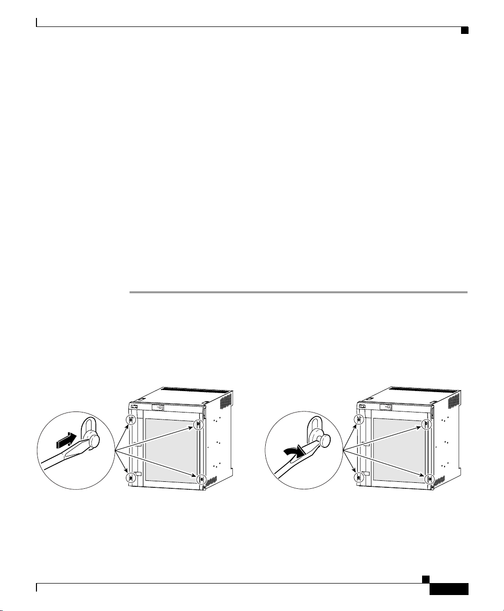
Step 1 Unlock each bezel plug by inserting the tip of a flat-blade screwdriver between
the top and bottom sections of the plug, and then rotating the screwdriver to
unlock the top portion of the plug (Figure 2).
Repeat this procedure for all four bezel plugs and then remove the plugs.
Adding or Replacing an AC PEM
Figure 2 Unlocking the Bezel Plugs
FA
N
S
O
K
F
A
N
F
A
IL
U
R
E
M
U
L
T
I-F
A
N
F
A
ILU
R
E
C
isco 10000
P
O
W
E
R
F
A
U
L
T
M
IS
W
IR
E
P
O
W
E
R
P
O
W
E
R
F
A
U
L
T
F
A
U
L
T
M
IS
W
IR
E
M
IS
W
IR
E
78-10832-01
F
A
N
S
O
K
F
A
N
F
A
IL
U
R
E
M
U
L
T
I-F
A
N
F
A
IL
U
R
E
P
O
W
E
R
F
A
U
L
T
M
IS
W
IR
E
P
O
W
E
R
P
O
W
E
R
F
A
U
L
T
F
A
U
L
T
M
IS
W
IR
E
M
IS
W
IR
30038
E
Cisco 10000 ESR AC Power Entry Module Installation
C
isco 10000
30039
5
Page 6
Adding or Replacing an AC PEM
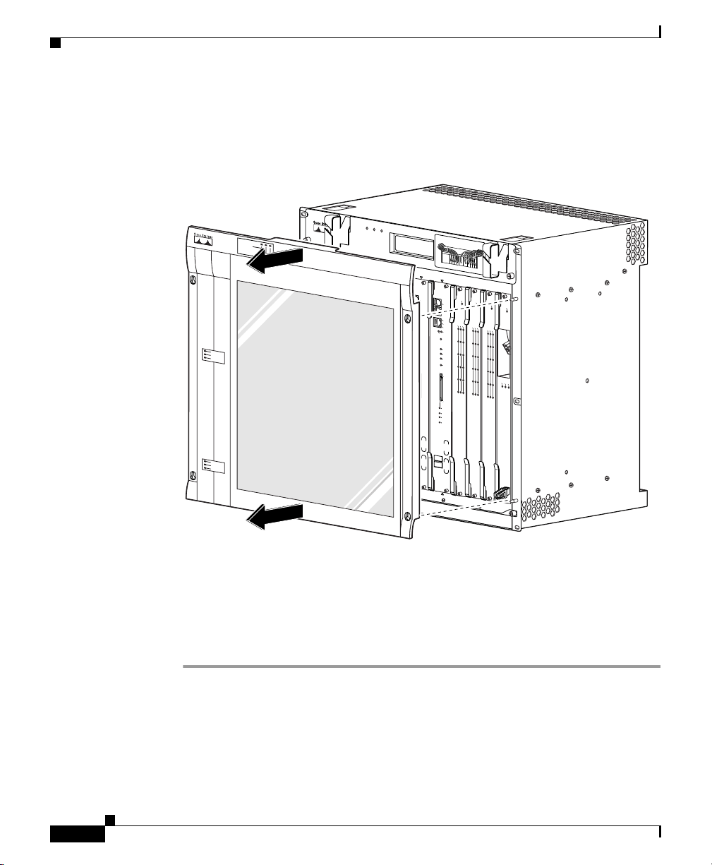
Step 2 Remove the cover by lifting it up slightly and then pulling it toward you
(Figure 3).
Figure 3 Removing the Front Cover
F
A
N
S
F
A
N
O
K
M
U
F
L
A
T
IL
I
-
U
R
E
F
A
N
F
A
IL
U
R
E
CAUTION
When hot swapping this fan tray,
0
C
A
GIGABIT ETHERNET
CISCO
10000
F
A
IL
R
A
R
L
A
IE
R
R
M
2
Cisco 10000
CISCO
10000
F
AIL
C
AR
A
LA
R
LO
IE
R
R
M
0
1
2
3
L
O
O
P
4
5
CH OC-12-DSO SM-IR
3
OP
6XCT3–DS0
C10000
CISCO
10000
6CT3
FA
C
AR
AL
RIER
A
R
M
CA
0
P
O
R
T
0
1
P
O
R
T
1
P
2
O
R
T
2
P
O
R
3
T
3
P
O
R
4
T
4
P
O
R
5
T
5
removal and replacement must
be done in under two minutes or
system shutdown will occur.
4
C
1
IL
F
A
IL
LO
O
P
P
O
ALARM
LO
ALARMS
6XCT3–DS0
0A
PROCESSOR ONLY
IS
C
O
0
0
0
0
CONSOLE
AUX
ACTIVITY
ETHERNET
LINK
A
LIN
C
T
IV
K
IT
Y
CRITICAL
MAJOR
MINO
R
ACO
S
L
O
T
0
STATUS
FAIL
BITS
PERFORMANCE ROUTING ENGINE
P/N
ESR-PRE3
0B
5
6
7
C
IS
C
O
1
0
0
0
0
C10000
CISCO
10000
6CT3
F
AIL
F
A
CONSOLE
IL
AUX
C
A
ACTIVITY
R
A
LA
R
LO
IER
R
OP
M
ETHERNET
CA
ALARM
0
P
LINK
O
LOO
R
T
0
A
L
C
IN
T
IV
K
ITY
1
P
O
R
T
1
ALARMS
C
RITICAL
P
2
O
R
T
2
MAJOR
MINOR
P
O
ACO
R
3
T
3
P
O
R
4
T
4
P
O
R
5
T
5
S
L
O
T
0
STATUS
FAIL
BITS
PERFORMANCE ROUTING ENGINE
P/N
ESR-PRE3
8
C10000
CISCO
C10000
CISCO
10000
6CT3
FA
CISCO
10000
6CT3
IL
F
10000
AIL
FAIL
F
A
IL
F
A
IL
C
A
R
A
LA
R
C
LO
IE
A
R
RR
AL
O
R
M
P
P
LO
A
IE
RM
R
O
R
OP
M
CA
ALA
0
P
P
O
LO
R
T
0
OP
CA
ALARM
0
P
O
LO
R
T
0
1
P
O
R
T
1
1
P
O
R
T
1
P
2
O
R
T
2
P
2
O
R
T
2
P
O
R
3
T
3
P
O
R
3
T
3
C
A
R
R
P
O
IE
R
4
T
4
TX
R
R
X
P
O
R
4
T
4
P
O
R
5
T
5
P
O
R
5
T
5
6XCT3–DS0
OC–12/STM–4 POS SM–IR
6XCT3–DS0
6XCT3–DS0
FANS OK
FAN
FAILURE
M
ULTI-FAN FAILURE
POW
FAULT
POW
ER
FAULT
M
ISW
IRE
POW
ER
FAULT
M
ISW
IRE
MISWIRE
POWER
FAULT
MISW
1
C
IS
CO
1
000
F
A
IL
ER
L
IN
T
K
R
X
X
IRE
PROCESSOR ONLY
30040
Step 3
Continue installing or replacing the AC PEM:
• If you are installing a second AC PEM, go to the “Installing a Second AC
PEM” section on page 7.
• If you are replacing an AC PEM, go to the “Replacing an AC PEM” section
on page 12.
Cisco 10000 ESR AC Power Entry Module Installation
6
78-10832-01
Page 7
Installing a Second AC PEM
Use the following procedure to install a second AC PEM in the bottom power bay
for redundancy.
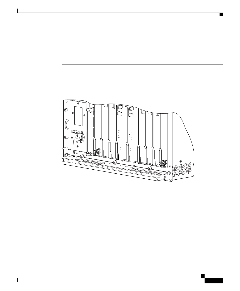
Step 1 Attach an antistatic wrist strap to your wrist and to an ESD socket on the chassis,
or to a bare metal surface on the chassis or frame (Figure 4).
Figure 4 ESD Chassis Connection
CISCO
10000
Adding or Replacing an AC PEM
5
5
5
5
5
POWER
FAULT
MISWIRE
ESD
socket
CH OC-12-DSO SM-IR
6XCT3–DS0
6XCT3–DS0
PERFORMANCE ROUTING ENGINE
A
C
O
C
R
IT
IC
A
M
L
A
J
O
R
M
IN
O
R
S
T
A
T
U
S
F
A
IL
PROCESSOR ONLY
PERFORMANCE ROUTING ENGINE
A
C
O
C
R
IT
IC
A
M
L
A
J
O
R
M
IN
6XCT3–DS0
O
R
S
T
A
T
U
S
F
A
IL
6XCT3–DS0
OC–12/STM–4 POS SM–IR
6XCT3–DS0
32236
78-10832-01
Cisco 10000 ESR AC Power Entry Module Installation
7
Page 8

Adding or Replacing an AC PEM
Step 2 Loosen the captive screws to remove the blank cover from the bottom power bay
(Figure 5).
Figure 5 Removing the Blank Cover
FANS
FAN
OK
MULTI-
FAILURE
FAN
FAILURE
C
A
U
T
W
IO
h
N
e
n
h
o
t s
w
a
re
p
m
p
in
o
v
g
a
th
l a
is
n
fa
d
re
n
b
tra
e
p
d
la
y
o
c
,
n
e
e
m
in
e
n
u
t m
n
s
d
y
u
e
s
s
r
te
tw
t
m
o
s
m
h
u
in
td
u
o
te
w
s
n
o
w
r
ill o
c
c
u
1
2
CISCO
10000
F
P
O
W
E
R
F
A
U
L
T
L
IN
T
K
X
3
CISCO
C
IS
10000
C
A
IL
O
1
0
F
0
0
0
A
IL
FAIL
C
A
R
A
L
R
LO
A
IE
R
O
R
M
P
0
1
2
3
C
A
R
A
R
R
L
X
L
A
IE
O
R
R
O
M
P
4
5
r.
4
0A
PROCESSOR
C
IS
C
O
1
0
0
0
C
0
IS
C
O
FAIL
1
0
0
0
0
C
ON
SO
LE
C
AU
A
R
A
X
L
R
L
A
IE
O
R
O
R
M
P
0
AC
TIV
ITY
E
THE
SLOT 0
SLOT 1
RN
LIN
ET
K
1
2
3
4
5
Captive
screws
Cisco 10000 ESR AC Power Entry Module Installation
8
GIGABIT ETHERNET
CH OC-12-DSO SM-IR
6XCT3–DS0
6XCT3–DS0
PROCESSOR
A
C
O
C
R
IT
IC
A
M
L
A
J
O
R
M
IN
O
R
S
T
A
T
U
S
F
A
IL
32692
78-10832-01
Page 9

Adding or Replacing an AC PEM
Step 3 Install the new AC PEM all the way into the power bay to ensure a secure
connection to the backplane, and then tighten the captive screws (Figure 6).
Figure 6 Installing an AC PEM
FANS
FAN
OK
MULTI-
FAILURE
FAN
FAILURE
1
2
CISCO
C
10000
IS
C
O
1
0
0
F
0
0
A
IL
F
A
I
L
P
O
W
E
R
F
A
U
L
T
L
C
IN
A
R
T
A
K
R
R
X
L
X
L
A
I
E
O
R
R
O
M
P
C
A
U
T
W
IO
h
N
e
n
h
o
t s
w
a
re
p
m
p
in
o
v
g
a
th
l a
is
n
fa
d
re
n
b
tr
e
p
d
la
a
y
o
c
,
n
e
e
m
in
e
n
u
t m
n
s
d
y
u
e
s
s
r tw
te
t
m
o
s
m
h
u
in
td
u
o
te
w
s
n
o
w
r
ill o
c
c
u
r
.
3
4
0A
PROCESSOR
C
IS
C
O
C
1
IS
0
C
0
0
O
0
1
FAIL
0
0
0
C
0
IS
C
O
FAIL
1
0
0
0
0
CO
NS
O
C
A
R
A
LA
R
L
IE
O
R
O
R
M
P
0
1
2
3
4
5
LE
C
A
A
U
R
A
X
L
R
LO
A
IE
R
O
R
M
P
0
AC
TIV
ITY
ETH
SLOT 0
ER
SLOT 1
LIN
NET
K
1
2
3
4
5
78-10832-01
Captive
screws
GIGABIT ETHERNET
CH OC-12-DSO SM-IR
P
O
W
E
R
FA
U
LT
6XCT3–DS0
6XCT3–DS0
A
C
O
C
R
IT
IC
A
M
L
A
J
O
R
M
IN
O
R
S
T
A
T
U
S
F
A
IL
PROCESSOR
32234
Cisco 10000 ESR AC Power Entry Module Installation
9
Page 10

Adding or Replacing an AC PEM
Step 4 Connect the power cord from the PEM to your power cord that connects to the
facility VAC input.
Step 5 Set the AC power cord connectors in a cord strain relief (canoe) to prevent them
from accidently disconnecting (Figure 7).
Figure 7 AC Power Cord Connectors in Canoes
1
F
A
N
S
F
A
N
O
K
M
U
F
L
A
T
IL
I-
U
R
E
F
A
N
F
A
IL
U
R
E
CA
UTION
W
hen hot swapping this fan tray,
removal and replacement m
be done in under two m
system shutdown will occur.
ust
O
CH OC-12-DSO SM-IR
inutes or
3
4
0A
PR
O
C
0B
E
SS
O
R
O
N
C
IS
C
O
1
0
00
0
F
A
IL
CARRIER
ALARM
CARRIER
LOOP
0
1
2
3
4
5
6XCT3–DS0
LY
C
IS
C
O
1
0
0
0
0
F
A
IL
ALARM
LOOP
0
S
S
L
L
O
O
T
0
1
2
3
4
5
6XCT3–DS0
5
6
C
IS
C
O
1
0
0
C
0
0
IS
1
0
C
O
N
S
O
L
E
A
U
X
A
C
T
I
V
I
T
E
Y
T
H
E
R
L
N
I
N
E
K
T
T
S
1
S
L
L
O
O
T
T
0
1
PERFORMANCE ROUTING ENGINE
A
C
O
A
C
O
C
R
IT
IC
C
A
R
M
L
IT
A
J
O
R
M
M
A
J
IN
O
O
R
M
IN
O
S
T
A
T
U
S
S
F
T
A
A
IL
T
F
A
IL
PR
O
CE
SSO
R
O
N
7
C
O
0
0
0
C
O
N
S
O
L
E
A
U
X
CARRIER
A
C
T
I
V
I
T
E
Y
T
H
E
R
0
L
N
I
N
E
K
T
1
2
3
4
5
PERFORMANCE ROUTING ENGINE
IC
A
L
R
R
U
S
8
C
IS
C
O
C
IS
C
O
1
0
00
0
C
1
IS
0
F
C
00
O
0
A
IL
F
C
IS
1
0
C
A
00
O
0
IL
F
1
0
0
A
0
0
IL
F
A
IL
A
CARR
LARM
LOOP
AL
C
LO
AR
IER
ARR
AL
OP
M
LOO
ARM
IE
R
0
P
0
1
1
2
2
3
3
CAR
RIER
4
TX
RX
4
5
5
OC–12/STM–4 POS SM–IR
6XCT3–DS0
6XCT3–DS0
6XCT3–DS0
LY
1
2
C
IS
C
O
C
ISC
1
0
0
0
0
10000
F
A
I
F
L
A
IL
POWER
FAULT
L
C
I
A
N
R
T
A
K
R
R
X
L
X
L
A
IE
O
R
R
O
M
P
GIGABIT ETHERNET
POWER
FAULT
10
Step 6
Plug the facility AC input power cord into a power receptacle.
Cisco 10000 ESR AC Power Entry Module Installation
32235
78-10832-01
Page 11

Step 7 Set the power switch to the on (|) position (Figure 8).
The (green) power LED on the PEM lights indicating that the PEM is on.
Figure 8 Setting the AC Power Switch to the On Position
F
A
N
S
F
A
N
O
K
M
U
F
L
A
T
I
I
L
-
U
R
E
F
A
N
F
A
I
L
U
R
E
C
A
U
T
W
IO
h
N
e
n
h
o
t s
w
a
re
p
m
p
in
o
v
g
a
th
l a
is
n
fa
d
re
n
b
tr
e
p
d
la
a
y
o
c
,
n
e
e
m
in
e
n
u
t
m
n
s
d
y
u
e
s
s
r
te
t
tw
m
o
s
m
h
u
in
td
u
o
te
w
s
n
o
w
r
ill o
c
c
u
r.
3
4
0A
P
R
O
C
0B
E
SSO
R
O
N
LY
C
IS
C
O
C
IS
1
C
0
O
0
00
F
1
0
0
A
0
0
IL
F
A
IL
C
ARR
ALA
C
LO
AR
IE
RM
ALAR
OP
R
RIER
LOO
M
P
0
0
S
S
L
L
O
T
0
1
1
2
2
3
3
4
4
5
5
6XCT3–DS0
6XCT3–DS0
5
C
IS
C
O
1
0
0
C
0
0
IS
C
O
1
0
0
0
0
C
IS
C
O
1
00
0
0
F
A
IL
C
O
N
S
O
C
L
O
E
N
S
O
L
A
E
U
X
A
U
X
A
C
T
CAR
I
V
I
T
A
E
ALARM
Y
C
T
RIER
T
H
LOO
I
E
V
R
I
T
L
E
N
Y
I
P
N
T
O
E
H
K
T
T
S
E
S
R
1
L
0
L
L
N
O
I
N
O
E
T
K
T
T
0
1
1
2
3
4
5
PERFORMANCE ROUTING ENGINE
PERFORMANCE ROUTING ENGINE
A
C
O
A
C
O
C
R
IT
IC
C
A
R
M
L
IT
A
J
IC
O
A
R
M
L
M
A
J
IN
O
O
R
R
M
IN
6XCT3–DS0
O
R
S
T
A
T
U
S
S
F
T
A
A
IL
T
U
S
F
A
IL
PR
O
C
E
SS
O
R
O
N
LY
POWER
FAULT
1
2
C
I
S
C
O
C
IS
1
C
0
0
O
0
0
10
000
F
A
I
F
L
A
IL
POWER
FAULT
L
C
I
A
N
R
T
A
K
R
R
X
L
X
L
A
IE
O
R
R
O
M
P
GIGABIT ETHERNET
CH OC-12-DSO SM-IR
POWER
FAULT
Adding or Replacing an AC PEM
6
7
8
C
IS
C
O
C
10
IS
C
0
0
O
0
F
C
IS
1
0
C
A
0
O
0
0
I
L
F
1
0
0
A
0
0
IL
F
A
I
L
C
ARRIER
A
LARM
CAR
LOO
AL
RIER
P
LOO
AR
M
0
P
0
1
1
2
2
3
3
C
ARRIER
4
T
R
X
X
4
5
5
OC–12/STM–4 POS SM–IR
6XCT3–DS0
6XCT3–DS0
78-10832-01
Step 8
32231
Replace the front cover.
Cisco 10000 ESR AC Power Entry Module Installation
11
Page 12

Adding or Replacing an AC PEM
Replacing an AC PEM
Use the following procedure to replace an AC PEM.
Note The illustrations in this guide show how to replace the AC PEM from
the bottom power bay. The procedure is the same to replace an
AC PEM in the top power bay.
Step 1 Attach an antistatic wrist strap to your wrist and to an ESD socket on the chassis,
or to a bare metal surface on the chassis or frame (Figure 9).
Figure 9 ESD Chassis Connection
5
5
5
CISCO
10000
5
5
12
POWER
FAULT
MISWIRE
CH OC-12-DSO SM-IR
6XCT3–DS0
6XCT3–DS0
A
C
O
C
R
IT
M
A
J
M
IN
S
T
A
F
A
IL
PROCESSOR ONLY
ESD
socket
Cisco 10000 ESR AC Power Entry Module Installation
PERFORMANCE ROUTING ENGINE
PERFORMANCE ROUTING ENGINE
A
C
O
IC
C
A
R
L
IT
IC
O
A
R
M
L
A
J
O
O
R
R
M
IN
6XCT3–DS0
O
R
T
U
S
S
T
A
T
U
S
F
A
IL
6XCT3–DS0
OC–12/STM–4 POS SM–IR
6XCT3–DS0
32236
78-10832-01
Page 13

Adding or Replacing an AC PEM
Step 2 Power off the PEM you are replacing (Figure 10).
Caution Do not power off both AC PEMs in a redundant system or the system
shuts down and all data traffic stops. Only power off the AC PEM
you are replacing.
Figure 10 Setting the AC Power Switch to the Off Position
FANS
FAN
O
K
M
ULTI-
FAILURE
F
AN
FAILURE
C
A
U
T
W
IO
h
N
e
n
h
o
t s
w
a
re
p
m
p
in
o
va
g
th
l a
is
n
fa
d
re
n
b
tra
e
p
d
la
y
o
c
,
n
e
e
m
in
e
n
u
t m
n
s
d
y
u
e
s
s
r tw
te
t
m
o
s
m
h
u
in
td
u
o
te
w
s
n
o
w
r
ill o
c
c
u
r.
3
4
0
A
P
R
O
C
0
E
B
S
S
O
R
O
N
CISCO
10000
F
A
IL
CAR
ALAR
CARR
RIER
LO
OP
M
0
0
P
O
R
1
1
P
O
R
2
P
2
O
R
3
P
O
R
3
4
P
O
R
4
5
P
O
R
5
6XCT3–DS0
L
Y
C
CISCO
1
0
00
0
10000
6
C
T
3
F
A
I
L
F
A
IL
ALA
LO
IE
RM
OP
R
M
R
P
A
LA
O
C
A
O
L
T0
T
1
T
2
T
3
T
4
T
5
6XCT3–DS0
5
C
IS
C
O
1
0
0
0
0
C
O
N
S
O
L
E
A
U
X
A
C
T
IV
IT
E
Y
T
H
E
R
L
N
IN
E
K
T
ACT
L
INK
IV
ITY
ALA
R
M
S
C
R
IT
IC
M
A
A
L
J
O
R
M
I
N
O
R
A
C
O
SLO
T 0
S
T
A
T
U
F
S
A
IL
B
IT
S
PERFORMANCE ROUTING ENGINE
P/N
ESR-PRE3
P
R
O
C
E
S
6
7
C
IS
C
O
1
0
0
0
0
C
O
N
S
O
L
E
A
U
X
CAR
A
C
RIER
T
I
V
IT
E
Y
T
H
E
R
0
P
L
O
N
R
T0
I
N
E
K
T
ACTI
LIN
K
VITY
1
P
O
R
T
1
ALA
R
M
S
C
R
I
T
P
2
O
R
IC
T
2
M
A
A
L
J
O
R
M
IN
O
R
P
O
A
R
3
T
3
C
O
P
O
R
4
T
4
P
O
R
5
T
5
SLO
T 0
S
T
A
T
U
F
S
A
IL
B
IT
S
PERFORMANCE ROUTING ENGINE
P/N
ESR-PRE3
S
O
R
O
N
L
Y
8
C
CISCO
1
0
00
0
C
CISCO
10
0
00
10000
6
C
T
3
C
CISCO
1
10000
6
00
F
C
T3
00
A
I
L
F
CISCO
10000
6C
A
T
3
I
L
F
10000
A
I
L
F
F
A
IL
A
IL
F
A
IL
F
AIL
AL
CARR
LOOP
ARM
AL
CA
LO
AR
IE
M
RRIER
A
OP
R
R
M
P
LA
A
LA
O
LOO
C
A
O
M
L
R
RM
P
A
A
L
O
C
A
0
P
P
O
LO
R
T
M
0
R
P
A
LA
O
C
A
0
O
P
O
L
R
T
0
1
P
O
R
T
1
1
P
O
R
T
1
P
2
O
R
T
2
P
2
O
R
T
2
P
O
R
3
T
3
P
O
R
3
T
3
C
AR
RIE
P
O
R
4
T
4
TX
R
R
X
P
O
R
4
T
4
P
O
R
5
T
5
P
O
R
5
T
5
OC–12/STM–4 POS SM–IR
6XCT3–DS0
6XCT3–DS0
6XCT3–DS0
POWER
FAULT
1
2
C
IS
C
O
C
IS
1
C
0
0
O
0
0
1
0
0
0
0
F
AIL
F
A
IL
POWER
FAULT
LIN
C
A
R
TX
A
K
RX
R
L
L
A
IE
O
R
R
O
M
P
GIGABIT ETHERNET
CH OC-12-DSO SM-IR
POWER
FAULT
78-10832-01
30026
Cisco 10000 ESR AC Power Entry Module Installation
13
Page 14

Adding or Replacing an AC PEM
Step 3 Remove the PEM power cable from its canoe and disconnect it from the AC input
power cable (Figure 11).
Figure 11 AC Power Cord Connectors in Canoes
1
F
A
N
S
F
A
N
O
K
M
U
F
L
A
T
IL
I-
U
R
E
F
A
N
F
A
IL
U
R
E
CAUTION
W
hen hot swapping this fan tray,
rem
oval and replacement must
be done in under two m
system
shutdown will occur.
O
0
CH OC-12-DSO SM-IR
inutes or
3
4
0A
PR
O
C
0B
E
SS
O
R
O
N
C
IS
C
O
1
0
0
0
0
F
A
IL
CARRIER
ALARM
CARRIER
LOOP
0
1
2
3
4
5
6XCT3–DS0
LY
C
IS
C
O
1
0
0
0
0
F
A
IL
ALARM
LO
OP
0
S
S
L
L
O
O
T
0
1
2
3
4
5
6XCT3–DS0
5
6
C
IS
C
O
10
0
C
0
0
IS
1
0
C
O
N
S
O
L
E
A
U
X
A
C
T
I
V
I
T
E
Y
T
H
E
R
L
N
I
N
E
K
T
T
S
1
S
L
L
O
O
T
T
0
1
PERFORMANCE ROUTING ENGINE
A
C
O
A
C
O
C
R
IT
IC
C
A
R
M
L
IT
A
JO
R
M
M
A
J
IN
O
O
R
M
IN
O
S
T
A
T
U
S
S
F
T
A
A
IL
T
F
A
IL
P
R
O
CE
S
SO
R
O
N
7
C
O
00
0
C
O
N
S
O
L
E
A
U
X
CA
A
RRIER
C
T
I
V
I
T
E
Y
T
H
E
R
0
L
N
I
N
E
K
T
1
2
3
4
5
PERFORMANCE ROUTING ENGINE
IC
A
L
R
R
U
S
8
C
IS
C
O
C
IS
C
O
1
0
0
0
0
C
1
IS
0
F
C
0
0
O
0
A
IL
F
C
IS
1
0
C
A
0
O
0
0
IL
F
10
0
A
0
0
IL
F
A
IL
A
CA
LARM
LO
RRIER
A
LAR
OP
CA
LOO
RR
A
M
LARM
P
LOOP
IER
0
0
1
1
2
2
3
3
C
ARR
IER
4
TX
R
X
4
5
5
OC–12/STM–4 POS SM–IR
6XCT3–DS0
6XCT3–DS0
6XCT3–DS0
LY
1
2
C
I
S
C
O
C
IS
1
C
0
0
0
0
1000
F
A
I
F
L
A
IL
POWER
FAULT
L
C
I
A
N
R
T
A
K
R
R
X
L
X
L
A
IE
O
R
R
O
M
P
GIGABIT ETHERNET
POWER
FAULT
14
32235
Cisco 10000 ESR AC Power Entry Module Installation
78-10832-01
Page 15

Adding or Replacing an AC PEM
Step 4 Loosen the captive screws on the PEM and remove the PEM from the chassis
using the handle on the faceplate (Figure 12).
Figure 12 Removing an AC PEM
FANS
FAN
OK
MULTI-
FAILURE
FAN
Handle
Captive
screw
Captive
screw
FAILURE
1
2
CISCO
CISCO
10000
10000
F
A
IL
F
A
IL
P
O
W
E
R
F
A
U
LT
P
O
W
E
R
F
A
U
LT
L
C
IN
A
R
T
A
K
R
R
X
L
X
L
A
IE
O
R
R
O
M
P
GIGABIT ETHERNET
CH OC-12-DSO SM-IR
C
A
U
T
W
IO
h
N
e
n
h
o
t s
w
a
r
e
p
m
p
in
o
v
g
a
th
l a
is
n
fa
d
re
n
b
tra
e
p
d
la
y
o
c
,
n
e
e
m
in
e
n
u
t m
n
s
d
y
u
e
s
s
r tw
te
t
m
o
s
m
h
u
in
td
u
o
te
w
s
n
o
w
r
ill o
c
c
u
r.
3
4
0A
PROCESSOR
C
IS
C
O
C
1
IS
0
C
0
0
O
0
1
FAIL
0
0
0
C
0
IS
C
O
FAIL
1
0
0
0
0
CO
N
S
O
C
A
R
A
L
R
LO
A
IE
R
O
R
M
P
0
1
2
3
4
5
6XCT3–DS0
LE
C
A
A
UX
R
A
LA
R
L
IE
O
R
O
R
M
P
0
AC
TIVITY
ETH
SLOT 0
ER
SLOT 1
LINK
NE
6XCT3–DS0
T
A
C
O
C
R
IT
IC
A
M
L
A
J
O
R
M
IN
O
R
S
T
A
T
U
S
F
A
IL
1
2
3
4
5
78-10832-01
PROCESSOR
32234
Cisco 10000 ESR AC Power Entry Module Installation
15
Page 16

Adding or Replacing an AC PEM
Step 5 Install the new PEM all the way into the power bay to ensure a good connection
to the backplane, and tighten the captive screws on the PEM (Figure 13).
Figure 13 Installing an AC PEM
FANS
FAN
OK
MULTI-
FAILURE
FAN
FAILURE
1
2
CISCO
C
10000
IS
C
O
1
0
0
F
0
0
A
IL
F
A
I
L
P
O
W
E
R
F
A
U
L
T
L
C
IN
A
R
T
A
K
R
R
X
L
X
L
A
I
E
O
R
R
O
M
P
C
A
U
T
W
IO
h
N
e
n
h
o
t s
w
a
re
p
m
p
in
o
v
g
a
th
l a
is
n
fa
d
re
n
b
tr
e
p
d
la
a
y
o
c
,
n
e
e
m
in
e
n
u
t m
n
s
d
y
u
e
s
s
r tw
te
t
m
o
s
m
h
u
in
td
u
o
te
w
s
n
o
w
r
ill o
c
c
u
r
.
3
4
0A
PROCESSOR
C
IS
C
O
C
1
IS
0
C
0
0
O
0
1
FAIL
0
0
0
C
0
IS
C
O
FAIL
1
0
0
0
0
CO
NS
O
C
A
R
A
LA
R
L
IE
O
R
O
R
M
P
0
1
2
3
4
5
LE
C
A
A
U
R
A
X
L
R
LO
A
IE
R
O
R
M
P
0
AC
TIV
ITY
ETH
SLOT 0
ER
SLOT 1
LIN
NET
K
1
2
3
4
5
16
Captive
screws
P
O
W
E
R
FA
U
LT
Cisco 10000 ESR AC Power Entry Module Installation
GIGABIT ETHERNET
CH OC-12-DSO SM-IR
6XCT3–DS0
6XCT3–DS0
PROCESSOR
A
C
O
C
R
IT
IC
A
M
L
A
J
O
R
M
IN
O
R
S
T
A
T
U
S
F
A
IL
32234
78-10832-01
Page 17

Adding or Replacing an AC PEM
Step 6 Connect the power cord from the PEM to the power cord that connects to the
facility VAC input.
Step 7 Set the AC power cord connectors in a cord strain relief (canoe) to prevent them
from accidently disconnecting (Figure 14).
Figure 14 AC Power Cord Connectors in Canoes
1
F
A
N
S
F
A
N
O
K
M
U
F
L
A
T
IL
I-
U
R
E
F
A
N
F
A
IL
U
R
E
CA
UTION
W
hen hot swapping this fan tray,
removal and replacement m
be done in under two m
system shutdown will occur.
ust
O
CH OC-12-DSO SM-IR
inutes or
3
4
0A
PR
O
C
0B
E
SS
O
R
O
N
C
IS
C
O
1
0
00
0
F
A
IL
CARRIER
ALARM
CARRIER
LOOP
0
1
2
3
4
5
6XCT3–DS0
LY
C
IS
C
O
1
0
0
0
0
F
A
IL
ALARM
LOOP
0
S
S
L
L
O
O
T
0
1
2
3
4
5
6XCT3–DS0
5
6
C
IS
C
O
1
0
0
C
0
0
IS
1
0
C
O
N
S
O
L
E
A
U
X
A
C
T
I
V
I
T
E
Y
T
H
E
R
L
N
I
N
E
K
T
T
S
1
S
L
L
O
O
T
T
0
1
PERFORMANCE ROUTING ENGINE
A
C
O
A
C
O
C
R
IT
IC
C
A
R
M
L
IT
A
J
O
R
M
M
A
J
IN
O
O
R
M
IN
O
S
T
A
T
U
S
S
F
T
A
A
IL
T
F
A
IL
PR
O
CE
SSO
R
O
N
7
C
O
0
0
0
C
O
N
S
O
L
E
A
U
X
CARRIER
A
C
T
I
V
I
T
E
Y
T
H
E
R
0
L
N
I
N
E
K
T
1
2
3
4
5
PERFORMANCE ROUTING ENGINE
IC
A
L
R
R
U
S
8
C
IS
C
O
C
IS
C
O
1
0
00
0
C
1
IS
0
F
C
00
O
0
A
IL
F
C
IS
1
0
C
A
00
O
0
IL
F
1
0
0
A
0
0
IL
F
A
IL
A
CARR
LARM
LOOP
AL
C
LO
AR
IER
ARR
AL
OP
M
LOO
ARM
IE
R
0
P
0
1
1
2
2
3
3
CAR
RIER
4
TX
RX
4
5
5
OC–12/STM–4 POS SM–IR
6XCT3–DS0
6XCT3–DS0
6XCT3–DS0
LY
1
2
C
IS
C
O
C
ISC
1
0
0
0
0
10000
F
A
I
F
L
A
IL
POWER
FAULT
L
C
I
A
N
R
T
A
K
R
R
X
L
X
L
A
IE
O
R
R
O
M
P
GIGABIT ETHERNET
POWER
FAULT
78-10832-01
Step 8
32235
Plug the facility AC input power cord into a power receptacle.
Cisco 10000 ESR AC Power Entry Module Installation
17
Page 18

Adding or Replacing an AC PEM
Step 9 Set the power switch to the on (|) position (Figure 15).
The (green) power LED on the PEM lights indicating that the PEM is on.
Figure 15 Setting the AC Power Switch to the On Position
POWER
FAULT
F
A
N
S
F
A
N
O
K
M
U
F
L
A
T
I
I
L
-
U
R
E
F
A
N
F
A
I
L
U
R
E
C
A
U
T
W
IO
h
N
e
n
h
o
t s
w
a
re
p
m
p
in
o
v
g
a
th
l a
is
n
fa
d
re
n
b
tr
e
p
d
la
a
y
o
c
,
n
e
e
m
in
e
n
u
t
m
n
s
d
y
u
e
s
s
r
te
t
tw
m
o
s
m
h
u
in
td
u
o
te
w
s
n
o
w
r
ill o
c
c
u
1
2
C
I
S
C
O
C
IS
1
C
0
0
O
0
0
10
000
F
A
I
F
L
A
IL
POWER
FAULT
L
C
I
A
N
R
T
A
K
R
R
X
L
X
L
A
IE
O
R
R
O
M
P
GIGABIT ETHERNET
CH OC-12-DSO SM-IR
POWER
FAULT
r.
3
4
0A
P
R
O
C
0B
E
SSO
R
O
N
LY
C
IS
C
O
C
IS
1
C
0
O
0
00
F
1
0
0
A
0
0
IL
F
A
IL
C
ARR
ALA
C
LO
AR
IE
RM
ALAR
OP
R
RIER
LOO
M
P
0
0
S
S
L
L
O
T
0
1
1
2
2
3
3
4
4
5
5
6XCT3–DS0
6XCT3–DS0
5
6
C
IS
C
O
1
0
0
C
0
0
IS
1
0
0
C
O
N
S
O
L
E
A
U
X
A
C
T
I
V
I
T
E
Y
T
H
E
R
L
N
I
N
O
E
K
T
T
S
S
1
L
L
O
O
T
T
0
1
PERFORMANCE ROUTING ENGINE
A
C
O
A
C
O
C
R
IT
IC
C
A
R
M
L
IT
A
J
IC
O
R
M
M
A
J
IN
O
O
R
R
M
IN
O
R
S
T
A
T
U
S
S
F
T
A
A
IL
T
U
F
A
IL
PR
O
C
E
SS
O
R
O
N
LY
7
C
O
0
0
C
O
N
S
O
L
E
A
U
X
CAR
A
C
RIER
T
I
V
I
T
E
Y
T
H
E
R
0
L
N
I
N
E
K
T
1
2
3
4
5
PERFORMANCE ROUTING ENGINE
A
L
S
8
C
IS
C
O
C
IS
C
O
1
00
0
0
C
10
IS
F
C
0
0
O
0
A
IL
F
C
IS
1
0
C
A
0
O
0
0
I
L
F
1
0
0
A
0
0
IL
F
A
I
L
ALARM
C
ARRIER
LOO
A
LARM
CAR
LOO
P
AL
RIER
P
LOO
AR
M
0
P
0
1
1
2
2
3
3
C
ARRIER
4
T
R
X
X
4
5
5
OC–12/STM–4 POS SM–IR
6XCT3–DS0
6XCT3–DS0
6XCT3–DS0
18
Step 10
Replace the front cover.
Cisco 10000 ESR AC Power Entry Module Installation
32231
78-10832-01
Page 19

Troubleshooting the Installation
Table 1 contains troubleshooting information for the AC PEM:
Table 1 AC PEM Troubleshooting
Symptom Description
System fails to power on Check that:
AC PEM Fault LED is on
(yellow)
Adding or Replacing an AC PEM
• All AC power cords are properly
connected to the Cisco 10000 and
at the power connection end.
• The PEM power switches are in
the On position.
–
The AC PEM POWER LED
should be on (green).
• The blower module is fully
inserted and the FANS OK LED is
on (green).
The PEM is not operating correctly
(see the Cisco 10000 ESR
Troubleshooting Guide).
78-10832-01
Cisco 10000 ESR AC Power Entry Module Installation
19
Page 20

FCC Class A Compliance
FCC Class A Compliance
This equipment has been tested and found to comply with the limits for a Class A
digital device, pursuant to part 15 of the FCC rules. These limits are designed to
provide reasonable protection against harmful interference when the equipment is
operated in a commercial environment. This equipment generates, uses, and can
radiate radio-frequency energy and, if not installed and used in accordance with
the instruction manual, may cause harmful interference to radio communications.
Operation of this equipment in a residential area is likely to cause harmful
interference, in which case users will be required to correct the interference at
their own expense.
You can determine whether your equipment is causing interference by turning it
off. If the interference stops, it was probably caused by the Cisco equipment or
one of its peripheral devices. If the equipment causes interference to radio or
television reception, try to correct the interference by using one or more of the
following measures:
• Turn the television or radio antenna until the interference stops.
• Move the equipment to one side or the other of the television or radio.
• Move the equipment farther away from the television or radio.
• Plug the equipment into an outlet that is on a different circuit from the
television or radio. (That is, make certain the equipment and the television or
radio are on circuits controlled by different circuit breakers or fuses.)
Modifications to this product not authorized by Cisco Systems, Inc. could void the
FCC approval and negate your authority to operate the product.
Cisco Connection Online
Cisco Connection Online (CCO) is Cisco Systems’ primary, real-time support
channel. Maintenance customers and partners can self-register on CCO to obtain
additional information and services.
Cisco 10000 ESR AC Power Entry Module Installation
20
78-10832-01
Page 21

Cisco Connection Online
Available 24 hours a day, 7 days a week, CCO provides a wealth of standard and
value-added services to Cisco customers and business partners. CCO services
include product information, product documentation, software updates, release
notes, technical tips, the Bug Navigator, configuration notes, brochures,
descriptions of service offerings, and download access to public and authorized
files.
CCO serves a wide variety of users through two interfaces that are updated and
enhanced simultaneously: a character-based version and a multimedia version that
resides on the World Wide Web (WWW). The character-based CCO supports
Zmodem, Kermit, Xmodem, FTP, and Internet e-mail, and it is excellent for quick
access to information over lower bandwidths. The WWW version of CCO
provides richly formatted documents with photographs, figures, graphics, and
video, as well as hyperlinks to related information.
You can access CCO in the following ways:
• WWW: http://www.cisco.com
• WWW: http://www-europe.cisco.com
• WWW: http://www-china.cisco.com
• Telnet: cco.cisco.com
• Modem: From North America, 408 526-8070; from Europe,
33 1 64 46 40 82. Use the following terminal settings: VT100 emulation;
databits: 8; parity: none; stop bits: 1; and connection rates up to 28.8 kbps.
78-10832-01
For a copy of CCO’s Frequently Asked Questions (FAQ), contact
cco-help@cisco.com. For additional information, contact cco-team@cisco.com.
Note If you are a network administrator and need personal technical
assistance with a Cisco product that is under warranty or covered by
a maintenance contract, contact the Cisco Technical Assistance
Center (TAC) at 800 553-2447, 408 526-7209, or tac@cisco.com.
To obtain general information about Cisco Systems, Cisco products,
or upgrades, contact 800 553-6387, 408 526-7208, or
cs-rep@cisco.com.
Cisco 10000 ESR AC Power Entry Module Installation
21
Page 22

Documentation CD-ROM
Documentation CD-ROM
Cisco documentation and additional literature are available in a CD-ROM
package, which ships with your product. The Documentation CD-ROM, a
member of the Cisco Connection Family, is updated monthly. Therefore, it might
be more current than printed documentation. To order additional copies of the
Documentation CD-ROM, contact your local sales representative or call customer
service. The CD-ROM package is available as a single package or as an annual
subscription. You can also access Cisco documentation on the World Wide Web
at http://www.cisco.com, http://www-china.cisco.com, or
http://www-europe.cisco.com.
If you are reading Cisco product documentation on the World Wide Web, you can
submit comments electronically. Click Feedback in the toolbar and select
Documentation. After you complete the form, click Submit to send it to Cisco.
We appreciate your comments.
Access Registrar, AccessPath, Any to Any, AtmDirector, Browse with Me, CCDA, CCDE, CCDP, CCIE, CCNA, CCNP,
CCSI, CD-PAC, the Cisco logo, Cisco Certified Internetwork Expert logo, CiscoLink, the Cisco Management Connection
logo, the Cisco NetWo rk s logo, the Cisco Powered Network logo, Cisco Systems Capital, the Cisco Systems Capital logo,
Cisco Systems Networking Academy, the Cisco Systems Networking Academy logo, the Cisco Technologies logo,
ConnectWay, Fast Step, FireRunner, Follow Me Browsing, FormShare, GigaStack, IGX, Intelligence in the Optical Core,
Internet Quotient, IP/VC, Kernel Proxy, MGX, Natural Network Viewer, NetSonar, Network Registrar, the Networkers
logo, Packet, PIX, Point and Click Internetworking, Policy Builder, Precept, RateMUX, ScriptShare, Secure Script,
ServiceWay, Shop with Me, SlideCast, SMARTnet, SVX, The Cell, TrafficDirector, TransPath, ViewRunner, Virtual Loop
Carrier System, Virtual Voice Line, VlanDirector, Voice LAN, Wavelength Router, Workgroup Director, and Workgroup
Stack are trademarks; Changing the Way We Work, Live, Play, and Learn, Empowering the Internet Generation, The
Internet Economy, and The New Internet Economy are service marks; and Aironet, ASIST, BPX, Catalyst, Cisco, Cisco
IOS, the Cisco IOS logo, Cisco Systems, the Cisco Systems logo, the Cisco Systems Cisco Press logo, Enterprise/Solver,
EtherChannel, EtherSwitch, FastHub, FastLink, FastPAD, FastSwitch, GeoTel, IOS, IP/TV, IPX, LightStream,
LightSwitch, MICA, NetRanger, Post-Routing, Pre-Routing, Registrar, StrataView Plus, Stratm, TeleRouter, and VCO are
registered trademarks of Cisco Systems, Inc. or its affiliates in the U.S. and certain other countries. All other trademarks
mentioned in this document are the property of their respective owners. The use of the word partner does not imply a
partnership relationship between Cisco and any of its resellers. (0004R)
Copyright © 2000, Cisco Systems, Inc.
All rights reserved.
22
Cisco 10000 ESR AC Power Entry Module Installation
78-10832-01
 Loading...