

Page 1

Cisco IOS Software Configuration Guide
for Cisco Aironet Access Points
Cisco IOS Releases 12.4(3g)JA and 12.3(8)JEB
April 2007
Americas Headquarters
Cisco Systems, Inc.
170 West Tasman Drive
San Jose, CA 95134-1706
USA
http://www.cisco.com
Tel: 408 526-4000
800 553-NETS (6387)
Fax: 408 527-0883
Text Part Number: 0L-11350-01
Page 2

THE SPECIFICATIONS AND INFORMATION REGARDING THE PRODUCTS IN THIS MANUAL ARE SUBJECT TO CHANGE WITHOUT NOTICE. ALL
STATEMENTS, INFORMATION, AND RECOMMENDATIONS IN THIS MANUAL ARE BELIEVED TO BE ACCURATE BUT ARE PRESENTED WITHOUT
WARRANTY OF ANY KIND, EXPRESS OR IMPLIED. USERS MUST TAKE FULL RESPONSIBILITY FOR THEIR APPLICATION OF ANY PRODUCTS.
THE SOFTWARE LICENSE AND LIMITED WARRANTY FOR THE ACCOMPANYING PRODUCT ARE SET FORTH IN THE INFORMATION PACKET THAT
SHIPPED WITH THE PRODUCT AND ARE INCORPORATED HEREIN BY THIS REFERENCE. IF YOU ARE UNABLE TO LOCATE THE SOFTWARE LICENSE
OR LIMITED WARRANTY, CONTACT YOUR CISCO REPRESENTATIVE FOR A COPY.
The Cisco implementation of TCP header compression is an adaptation of a program developed by the University of California, Berkeley (UCB) as part of UCB’s public
domain version of the UNIX operating system. All rights reserved. Copyright © 1981, Regents of the University of California.
NOTWITHSTANDING ANY OTHER WARRANTY HEREIN, ALL DOCUMENT FILES AND SOFTWARE OF THESE SUPPLIERS ARE PROVIDED “AS IS” WITH
ALL FAULTS. CISCO AND THE ABOVE-NAMED SUPPLIERS DISCLAIM ALL WARRANTIES, EXPRESSED OR IMPLIED, INCLUDING, WITHOUT
LIMITATION, THOSE OF MERCHANTABILITY, FITNESS FOR A PARTICULAR PURPOSE AND NONINFRINGEMENT OR ARISING FROM A COURSE OF
DEALING, USAGE, OR TRADE PRACTICE.
IN NO EVENT SHALL CISCO OR ITS SUPPLIERS BE LIABLE FOR ANY INDIRECT, SPECIAL, CONSEQUENTIAL, OR INCIDENTAL DAMAGES, INCLUDING,
WITHOUT LIMITATION, LOST PROFITS OR LOSS OR DAMAGE TO DATA ARISING OUT OF THE USE OR INABILITY TO USE THIS MANUAL, EVEN IF CISCO
OR ITS SUPPLIERS HAVE BEEN ADVISED OF THE POSSIBILITY OF SUCH DAMAGES.
CCVP, the Cisco Logo, and the Cisco Square Bridge logo are trademarks of Cisco Systems, Inc.; Changing the Way We Work, Live, Play, and Learn is a service mark of
Cisco Systems, Inc.; and Access Registrar, Aironet, BPX, Catalyst, CCDA, CCDP, CCIE, CCIP, CCNA, CCNP, CCSP, Cisco, the Cisco Certified Internetwork Expert logo,
Cisco IOS, Cisco Press, Cisco Systems, Cisco Systems Capital, the Cisco Systems logo, Cisco Unity, Enterprise/Solver, EtherChannel, EtherFast, EtherSwitch, Fast Step,
Follow Me Browsing, FormShare, GigaDrive, GigaStack, HomeLink, Internet Quotient, IOS, iPhone, IP/TV, iQ Expertise, the iQ logo, iQ Net Readiness Scorecard, iQuick
Study, LightStream, Linksys, MeetingPlace, MGX, Networking Academy, Network Registrar, Packet, PIX, ProConnect, RateMUX, ScriptShare, SlideCast, SMARTnet,
StackWise, The Fastest Way to Increase Your Internet Quotient, and TransPath are registered trademarks of Cisco Systems, Inc. and/or its affiliates in the United States and
certain other countries.
All other trademarks mentioned in this document or Website are the property of their respective owners. The use of the word partner does not imply a partnership relationship
between Cisco and any other company. (0612R)
Cisco IOS Software Configuration Guide for Cisco Aironet Access Points
Copyright © 2007 Cisco Systems, Inc. All rights reserved.
Page 3

CONTENTS
Preface xix
Audience xix
Purpose xix
Organization xx
Conventions xxi
Related Publications xxiii
Obtaining Documentation, Obtaining Support, and Security Guidelines xxiv
CHAPTER
CHAPTER
1 Overview 1-1
Features 1-2
Features Introduced in This Release 1-2
Japan Upgrade Utility 1-2
Multiple VLAN and Rate Limiting Support for Point-to-Multipoint Bridging 1-3
Client MFP Support 1-3
Regulatory Changes for Taiwan 1-3
Universal Workgroup Bridge 1-4
Management Options 1-4
Roaming Client Devices 1-4
Network Configuration Examples 1-4
Root Access Point 1-5
Repeater Access Point 1-5
Bridges 1-6
Workgroup Bridge 1-7
Central Unit in an All-Wireless Network 1-8
2 Using the Web-Browser Interface 2-1
OL-11350-01
Using the Web-Browser Interface for the First Time 2-3
Using the Management Pages in the Web-Browser Interface 2-3
Using Action Buttons 2-4
Character Restrictions in Entry Fields 2-5
Enabling HTTPS for Secure Browsing 2-5
CLI Configuration Example 2-13
Deleting an HTTPS Certificate 2-13
Cisco IOS Software Configuration Guide for Cisco Aironet Access Points
iii
Page 4

Contents
Using Online Help 2-14
Changing the Location of Help Files 2-14
Disabling the Web-Browser Interface 2-15
CHAPTER
3 Using the Command-Line Interface 3-1
Cisco IOS Command Modes 3-2
Getting Help 3-3
Abbreviating Commands 3-3
Using no and default Forms of Commands 3-4
Understanding CLI Messages 3-4
Using Command History 3-4
Changing the Command History Buffer Size 3-5
Recalling Commands 3-5
Disabling the Command History Feature 3-5
Using Editing Features 3-6
Enabling and Disabling Editing Features 3-6
Editing Commands Through Keystrokes 3-6
Editing Command Lines that Wrap 3-7
Searching and Filtering Output of show and more Commands 3-8
Accessing the CLI 3-9
Opening the CLI with Telnet 3-9
Opening the CLI with Secure Shell 3-9
CHAPTER
iv
4 Configuring the Access Point for the First Time 4-1
Before You Start 4-2
Resetting the Device to Default Settings 4-2
Resetting to Default Settings Using the MODE Button 4-2
Resetting to Default Settings Using the GUI 4-2
Resetting to Default Settings Using the CLI 4-3
Obtaining and Assigning an IP Address 4-4
Default IP Address Behavior 4-4
Connecting to the 1100 Series Access Point Locally 4-5
Connecting to the 1130 Series Access Point Locally 4-6
Connecting to the 1200, 1230, and 1240 Series Access Points Locally 4-6
Connecting to the 1300 Series Access Point/Bridge Locally 4-7
Default Radio Settings 4-8
Assigning Basic Settings 4-8
Cisco IOS Software Configuration Guide for Cisco Aironet Access Points
OL-11350-01
Page 5

Default Settings on the Express Setup Page 4-14
Configuring Basic Security Settings 4-15
Understanding Express Security Settings 4-18
Using VLANs 4-18
Express Security Types 4-19
Express Security Limitations 4-21
Using the Express Security Page 4-21
CLI Configuration Examples 4-22
Configuring System Power Settings for 1130 and 1240 Series Access Points 4-27
Using the IP Setup Utility 4-28
Obtaining IPSU 4-28
Using IPSU to Find the Access Point’s IP Address 4-28
Assigning an IP Address Using the CLI 4-29
Using a Telnet Session to Access the CLI 4-30
Contents
CHAPTER
Configuring the 802.1X Supplicant 4-30
Creating a Credentials Profile 4-31
Applying the Credentials to an Interface or SSID 4-31
Applying the Credentials Profile to the Wired Port 4-32
Applying the Credentials Profile to an SSID Used For the Uplink 4-32
Creating and Applying EAP Method Profiles 4-33
5 Administering the Access PointWireless Device Access 5-1
Disabling the Mode Button 5-2
Preventing Unauthorized Access to Your Access Point 5-3
Protecting Access to Privileged EXEC Commands 5-3
Default Password and Privilege Level Configuration 5-4
Setting or Changing a Static Enable Password 5-4
Protecting Enable and Enable Secret Passwords with Encryption 5-6
Configuring Username and Password Pairs 5-7
Configuring Multiple Privilege Levels 5-8
Setting the Privilege Level for a Command 5-8
Logging Into and Exiting a Privilege Level 5-9
OL-11350-01
Controlling Access Point Access with RADIUS 5-9
Default RADIUS Configuration 5-10
Configuring RADIUS Login Authentication 5-10
Defining AAA Server Groups 5-12
Configuring RADIUS Authorization for User Privileged Access and
Network Services
5-14
Displaying the RADIUS Configuration 5-15
Cisco IOS Software Configuration Guide for Cisco Aironet Access Points
v
Page 6

Contents
Controlling Access Point Access with TACACS+ 5-15
Default TACACS+ Configuration 5-15
Configuring TACACS+ Login Authentication 5-15
Configuring TACACS+ Authorization for Privileged EXEC Access and Network Services 5-17
Displaying the TACACS+ Configuration 5-17
Configuring Ethernet Speed and Duplex Settings 5-18
Configuring the Access Point for Wireless Network Management 5-18
Configuring the Access Point for Local Authentication and Authorization 5-19
Configuring the Authentication Cache and Profile 5-20
Configuring the Access Point to Provide DHCP Service 5-22
Setting up the DHCP Server 5-22
Monitoring and Maintaining the DHCP Server Access Point 5-24
Show Commands 5-24
Clear Commands 5-25
Debug Command 5-25
Configuring the Access Point for Secure Shell 5-25
Understanding SSH 5-25
Configuring SSH 5-26
Configuring Client ARP Caching 5-26
Understanding Client ARP Caching 5-26
Optional ARP Caching 5-26
Configuring ARP Caching 5-27
Managing the System Time and Date 5-27
Understanding Simple Network Time Protocol 5-27
Configuring SNTP 5-28
Configuring Time and Date Manually 5-28
Setting the System Clock 5-28
Displaying the Time and Date Configuration 5-29
Configuring the Time Zone 5-29
Configuring Summer Time (Daylight Saving Time) 5-30
Defining HTTP Access 5-32
Configuring a System Name and Prompt 5-32
Default System Name and Prompt Configuration 5-32
Configuring a System Name 5-32
Understanding DNS 5-33
Default DNS Configuration 5-33
Setting Up DNS 5-34
Displaying the DNS Configuration 5-35
vi
Cisco IOS Software Configuration Guide for Cisco Aironet Access Points
OL-11350-01
Page 7

Creating a Banner 5-35
Default Banner Configuration 5-35
Configuring a Message-of-the-Day Login Banner 5-35
Configuring a Login Banner 5-37
Upgrading Autonomous Cisco Aironet Access Points to Lightweight Mode 5-37
Migrating to Japan W52 Domain 5-37
Verifying the Migration 5-39
Configuring Multiple VLAN and Rate Limiting for Point-to-Multipoint Bridging 5-39
CLI Command 5-40
Contents
CHAPTER
6 Configuring Radio Settings 6-1
Enabling the Radio Interface 6-2
Configuring the Role in Radio Network 6-2
Universal Workgroup Bridge Mode 6-5
Configuring Dual-Radio Fallback 6-5
Radio Tracking 6-6
Fast Ethernet Tracking 6-6
MAC-Address Tracking 6-6
Bridge Features Not Supported 6-7
Configuring Radio Data Rates 6-7
Configuring Radio Transmit Power 6-10
Limiting the Power Level for Associated Client Devices 6-12
Configuring Radio Channel Settings 6-13
Dynamic Frequency Selection 6-17
CLI Commands 6-18
Confirming that DFS is Enabled 6-18
Configuring a Channel 6-19
Blocking Channels from DFS Selection 6-20
OL-11350-01
Configuring Location-Based Services 6-21
Understanding Location-Based Services 6-21
Configuring LBS on Access Points 6-21
Enabling and Disabling World Mode 6-22
Disabling and Enabling Short Radio Preambles 6-23
Configuring Transmit and Receive Antennas 6-24
Enabling and Disabling Gratuitous Probe Response 6-25
Disabling and Enabling Aironet Extensions 6-26
Configuring the Ethernet Encapsulation Transformation Method 6-27
Enabling and Disabling Reliable Multicast to Workgroup Bridges 6-27
Cisco IOS Software Configuration Guide for Cisco Aironet Access Points
vii
Page 8

Contents
Enabling and Disabling Public Secure Packet Forwarding 6-28
Configuring Protected Ports 6-29
Configuring the Beacon Period and the DTIM 6-30
Configure RTS Threshold and Retries 6-30
Configuring the Maximum Data Retries 6-31
Configuring the Fragmentation Threshold 6-31
Enabling Short Slot Time for 802.11g Radios 6-32
Performing a Carrier Busy Test 6-32
Configuring VoIP Packet Handling 6-32
Viewing VoWLAN Metrics 6-33
Viewing Voice Reports 6-34
Viewing Wireless Client Reports 6-36
Viewing Voice Fault Summary 6-37
Configuring Voice QoS Settings 6-38
Configuring Voice Fault Settings 6-39
CHAPTER
7 Configuring Multiple SSIDs 7-1
Understanding Multiple SSIDs 7-2
Effect of Software Versions on SSIDs 7-2
Configuring Multiple SSIDs 7-4
Default SSID Configuration 7-4
Creating an SSID Globally 7-4
Viewing SSIDs Configured Globally 7-6
Using Spaces in SSIDs 7-6
Using a RADIUS Server to Restrict SSIDs 7-7
Configuring Multiple Basic SSIDs 7-7
Requirements for Configuring Multiple BSSIDs 7-8
Guidelines for Using Multiple BSSIDs 7-8
Configuring Multiple BSSIDs 7-8
CLI Configuration Example 7-10
Displaying Configured BSSIDs 7-10
Assigning IP Redirection for an SSID 7-11
Guidelines for Using IP Redirection 7-12
Configuring IP Redirection 7-12
viii
Including an SSID in an SSIDL IE 7-13
NAC Support for MBSSID 7-13
Configuring NAC for MBSSID 7-15
Cisco IOS Software Configuration Guide for Cisco Aironet Access Points
OL-11350-01
Page 9

Contents
CHAPTER
8 Configuring Spanning Tree Protocol 8-1
Understanding Spanning Tree Protocol 8-2
STP Overview 8-2
350 Series Bridge Interoperability 8-3
Access Point/Bridge Protocol Data Units 8-3
Election of the Spanning-Tree Root 8-4
Spanning-Tree Timers 8-5
Creating the Spanning-Tree Topology 8-5
Spanning-Tree Interface States 8-5
Blocking State 8-7
Listening State 8-7
Learning State 8-7
Forwarding State 8-8
Disabled State 8-8
Configuring STP Features 8-8
Default STP Configuration 8-8
Configuring STP Settings 8-9
STP Configuration Examples 8-10
Root Bridge Without VLANs 8-10
Non-Root Bridge Without VLANs 8-11
Root Bridge with VLANs 8-11
Non-Root Bridge with VLANs 8-13
CHAPTER
Displaying Spanning-Tree Status 8-14
9 Configuring an Access Point as a Local Authenticator 9-1
Understanding Local Authentication 9-2
Configuring a Local Authenticator 9-2
Guidelines for Local Authenticators 9-3
Configuration Overview 9-3
Configuring the Local Authenticator Access Point 9-3
Configuring Other Access Points to Use the Local Authenticator 9-6
Configuring EAP-FAST Settings 9-7
Configuring PAC Settings 9-7
Configuring an Authority ID 9-8
Configuring Server Keys 9-8
Possible PAC Failures Caused by Access Point Clock 9-8
Limiting the Local Authenticator to One Authentication Type 9-9
Unblocking Locked Usernames 9-9
Viewing Local Authenticator Statistics 9-9
OL-11350-01
Cisco IOS Software Configuration Guide for Cisco Aironet Access Points
ix
Page 10

Contents
Using Debug Messages 9-11
CHAPTER
CHAPTER
10 Configuring Cipher Suites and WEP 10-1
Understanding Cipher Suites and WEP 10-2
Configuring Cipher Suites and WEP 10-3
Creating WEP Keys 10-3
WEP Key Restrictions 10-5
Example WEP Key Setup 10-5
Enabling Cipher Suites and WEP 10-6
Matching Cipher Suites with WPA and CCKM 10-7
Enabling and Disabling Broadcast Key Rotation 10-7
11 Configuring Authentication Types 11-1
Understanding Authentication Types 11-2
Open Authentication to the Access Point 11-2
Shared Key Authentication to the Access Point 11-3
EAP Authentication to the Network 11-4
MAC Address Authentication to the Network 11-5
Combining MAC-Based, EAP, and Open Authentication 11-6
Using CCKM for Authenticated Clients 11-6
Using WPA Key Management 11-7
Software and Firmware Requirements for WPA, CCKM, CKIP, and WPA-TKIP 11-8
CHAPTER
x
Configuring Authentication Types 11-10
Assigning Authentication Types to an SSID 11-10
Configuring WPA Migration Mode 11-13
Configuring Additional WPA Settings 11-14
Configuring MAC Authentication Caching 11-15
Configuring Authentication Holdoffs, Timeouts, and Intervals 11-16
Creating and Applying EAP Method Profiles for the 802.1X Supplicant 11-17
Creating an EAP Method Profile 11-18
Applying an EAP Profile to the Fast Ethernet Interface 11-18
Applying an EAP Profile to an Uplink SSID 11-19
Matching Access Point and Client Device Authentication Types 11-19
12 Configuring WDS, Fast Secure Roaming, Radio Management, and Wireless Intrusion Detection
Services
12-1
Understanding WDS 12-2
Role of the WDS Device 12-2
Role of Access Points Using the WDS Device 12-3
Cisco IOS Software Configuration Guide for Cisco Aironet Access Points
OL-11350-01
Page 11

Understanding Fast Secure Roaming 12-3
Understanding Radio Management 12-5
Understanding Layer 3 Mobility 12-5
Understanding Wireless Intrusion Detection Services 12-6
Configuring WDS 12-7
Guidelines for WDS 12-8
Requirements for WDS 12-8
Configuration Overview 12-8
Configuring Access Points as Potential WDS Devices 12-9
CLI Configuration Example 12-13
Configuring Access Points to use the WDS Device 12-14
CLI Configuration Example 12-15
Configuring the Authentication Server to Support WDS 12-15
Configuring WDS Only Mode 12-20
Viewing WDS Information 12-21
Using Debug Messages 12-22
Contents
Configuring Fast Secure Roaming 12-22
Requirements for Fast Secure Roaming 12-22
Configuring Access Points to Support Fast Secure Roaming 12-23
CLI Configuration Example 12-25
Configuring Management Frame Protection 12-25
Management Frame Protection 12-25
Overview 12-26
Protection of Unicast Management Frames 12-26
Protection of Broadcast Management Frames 12-26
Client MFP For Access Points in Root mode 12-26
Configuring Client MFP 12-27
Configuring Radio Management 12-29
CLI Configuration Example 12-30
Configuring Access Points to Participate in WIDS 12-31
Configuring the Access Point for Scanner Mode 12-31
Configuring the Access Point for Monitor Mode 12-31
Displaying Monitor Mode Statistics 12-32
Configuring Monitor Mode Limits 12-33
Configuring an Authentication Failure Limit 12-33
OL-11350-01
Configuring WLSM Failover 12-33
Resilient Tunnel Recovery 12-33
Active/Standby WLSM Failover 12-34
Cisco IOS Software Configuration Guide for Cisco Aironet Access Points
xi
Page 12

Contents
CHAPTER
13 Configuring RADIUS and TACACS+ Servers 13-1
Configuring and Enabling RADIUS 13-2
Understanding RADIUS 13-2
RADIUS Operation 13-3
Configuring RADIUS 13-4
Default RADIUS Configuration 13-4
Identifying the RADIUS Server Host 13-5
Configuring RADIUS Login Authentication 13-7
Defining AAA Server Groups 13-9
Configuring RADIUS Authorization for User Privileged Access and Network Services 13-11
Configuring Packet of Disconnect 13-12
Starting RADIUS Accounting m 13-13
Selecting the CSID Format 13-14
Configuring Settings for All RADIUS Servers 13-15
Configuring the Access Point to Use Vendor-Specific RADIUS Attributes 13-16
Configuring the Access Point for Vendor-Proprietary RADIUS Server Communication 13-17
Configuring WISPr RADIUS Attributes 13-18
Displaying the RADIUS Configuration 13-19
RADIUS Attributes Sent by the Access Point 13-20
CHAPTER
Configuring and Enabling TACACS+ 13-23
Understanding TACACS+ 13-23
TACACS+ Operation 13-24
Configuring TACACS+ 13-24
Default TACACS+ Configuration 13-25
Identifying the TACACS+ Server Host and Setting the Authentication Key 13-25
Configuring TACACS+ Login Authentication 13-26
Configuring TACACS+ Authorization for Privileged EXEC Access and Network Services 13-27
Starting TACACS+ Accounting 13-28
Displaying the TACACS+ Configuration 13-29
14 Configuring VLANs 14-1
Understanding VLANs 14-2
Related Documents 14-3
Incorporating Wireless Devices into VLANs 14-4
Configuring VLANs 14-4
Configuring a VLAN 14-5
Assigning Names to VLANs 14-7
Guidelines for Using VLAN Names 14-7
Creating a VLAN Name 14-8
xii
Cisco IOS Software Configuration Guide for Cisco Aironet Access Points
OL-11350-01
Page 13

Using a RADIUS Server to Assign Users to VLANs 14-8
Using a RADIUS Server for Dynamic Mobility Group Assignment 14-9
Viewing VLANs Configured on the Access Point 14-9
VLAN Configuration Example 14-10
Contents
CHAPTER
15 Configuring QoS 15-1
Understanding QoS for Wireless LANs 15-2
QoS for Wireless LANs Versus QoS on Wired LANs 15-2
Impact of QoS on a Wireless LAN 15-2
Precedence of QoS Settings 15-3
Using Wi-Fi Multimedia Mode 15-4
Configuring QoS 15-5
Configuration Guidelines 15-5
Configuring QoS Using the Web-Browser Interface 15-5
The QoS Policies Advanced Page 15-9
QoS Element for Wireless Phones 15-9
IGMP Snooping 15-10
AVVID Priority Mapping 15-10
WiFi Multimedia (WMM) 15-10
Adjusting Radio Access Categories 15-10
Optimized Voice Settings 15-12
Configuring Call Admission Control 15-12
QoS Configuration Examples 15-13
Giving Priority to Voice Traffic 15-13
Giving Priority to Video Traffic 15-14
CHAPTER
OL-11350-01
16 Configuring Filters 16-1
Understanding Filters 16-2
Configuring Filters Using the CLI 16-2
Configuring Filters Using the Web-Browser Interface 16-3
Configuring and Enabling MAC Address Filters 16-3
Creating a MAC Address Filter 16-4
Using MAC Address ACLs to Block or Allow Client Association to the Access Point 16-6
ACL Logging 16-8
CLI Configuration Example 16-8
Configuring and Enabling IP Filters 16-8
Creating an IP Filter 16-10
Configuring and Enabling Ethertype Filters 16-11
Creating an Ethertype Filter 16-12
Cisco IOS Software Configuration Guide for Cisco Aironet Access Points
xiii
Page 14

Contents
CHAPTER
CHAPTER
17 Configuring CDP 17-1
Understanding CDP 17-2
Configuring CDP 17-2
Default CDP Configuration 17-2
Configuring the CDP Characteristics 17-2
Disabling and Enabling CDP 17-3
Disabling and Enabling CDP on an Interface 17-4
Monitoring and Maintaining CDP 17-4
18 Configuring SNMP 18-1
Understanding SNMP 18-2
SNMP Versions 18-2
SNMP Manager Functions 18-3
SNMP Agent Functions 18-4
SNMP Community Strings 18-4
Using SNMP to Access MIB Variables 18-4
Configuring SNMP 18-5
Default SNMP Configuration 18-5
Enabling the SNMP Agent 18-5
Configuring Community Strings 18-6
Specifying SNMP-Server Group Names 18-7
Configuring SNMP-Server Hosts 18-8
Configuring SNMP-Server Users 18-8
Configuring Trap Managers and Enabling Traps 18-8
Setting the Agent Contact and Location Information 18-10
Using the snmp-server view Command 18-10
SNMP Examples 18-10
CHAPTER
xiv
Displaying SNMP Status 18-12
19 Configuring Repeater and Standby Access Points and Workgroup Bridge Mode 19-1
Understanding Repeater Access Points 19-2
Configuring a Repeater Access Point 19-3
Default Configuration 19-4
Guidelines for Repeaters 19-4
Setting Up a Repeater 19-5
Aligning Antennas 19-6
Verifying Repeater Operation 19-6
Setting Up a Repeater As a LEAP Client 19-7
Cisco IOS Software Configuration Guide for Cisco Aironet Access Points
OL-11350-01
Page 15

Setting Up a Repeater As a WPA Client 19-8
Understanding Hot Standby 19-8
Configuring a Hot Standby Access Point 19-9
Verifying Standby Operation 19-12
Understanding Workgroup Bridge Mode 19-13
Treating Workgroup Bridges as Infrastructure Devices or as Client Devices 19-14
Configuring a Workgroup Bridge for Roaming 19-15
Configuring a Workgroup Bridge for Limited Channel Scanning 19-15
Configuring the Limited Channel Set 19-15
Ignoring the CCX Neighbor List 19-16
Configuring a Client VLAN 19-16
Configuring Workgroup Bridge Mode 19-16
The Workgroup Bridge in a Lightweight Environment 19-18
Guidelines for Using Workgroup Bridges in a Lightweight Environment 19-18
Sample Workgroup Bridge Configuration 19-20
Contents
CHAPTER
20 Managing Firmware and Configurations 20-1
Working with the Flash File System 20-2
Displaying Available File Systems 20-2
Setting the Default File System 20-3
Displaying Information About Files on a File System 20-3
Changing Directories and Displaying the Working Directory 20-4
Creating and Removing Directories 20-4
Copying Files 20-5
Deleting Files 20-5
Creating, Displaying, and Extracting tar Files 20-6
Creating a tar File 20-6
Displaying the Contents of a tar File 20-6
Extracting a tar File 20-7
Displaying the Contents of a File 20-8
Working with Configuration Files 20-8
Guidelines for Creating and Using Configuration Files 20-9
Configuration File Types and Location 20-9
Creating a Configuration File by Using a Text Editor 20-10
Copying Configuration Files by Using TFTP 20-10
Preparing to Download or Upload a Configuration File by Using TFTP 20-10
Downloading the Configuration File by Using TFTP 20-11
Uploading the Configuration File by Using TFTP 20-11
Copying Configuration Files by Using FTP 20-12
OL-11350-01
Cisco IOS Software Configuration Guide for Cisco Aironet Access Points
xv
Page 16

Contents
Preparing to Download or Upload a Configuration File by Using FTP 20-13
Downloading a Configuration File by Using FTP 20-13
Uploading a Configuration File by Using FTP 20-14
Copying Configuration Files by Using RCP 20-15
Preparing to Download or Upload a Configuration File by Using RCP 20-16
Downloading a Configuration File by Using RCP 20-16
Uploading a Configuration File by Using RCP 20-17
Clearing Configuration Information 20-18
Deleting a Stored Configuration File 20-18
Working with Software Images 20-18
Image Location on the Access Point 20-19
tar File Format of Images on a Server or Cisco.com 20-19
Copying Image Files by Using TFTP 20-20
Preparing to Download or Upload an Image File by Using TFTP 20-20
Downloading an Image File by Using TFTP 20-21
Uploading an Image File by Using TFTP 20-22
Copying Image Files by Using FTP 20-23
Preparing to Download or Upload an Image File by Using FTP 20-23
Downloading an Image File by Using FTP 20-24
Uploading an Image File by Using FTP 20-26
Copying Image Files by Using RCP 20-27
Preparing to Download or Upload an Image File by Using RCP 20-27
Downloading an Image File by Using RCP 20-29
Uploading an Image File by Using RCP 20-31
Reloading the Image Using the Web Browser Interface 20-32
Browser HTTP Interface 20-32
Browser TFTP Interface 20-33
CHAPTER
xvi
21 Configuring System Message Logging 21-1
Understanding System Message Logging 21-2
Configuring System Message Logging 21-2
System Log Message Format 21-2
Default System Message Logging Configuration 21-3
Disabling and Enabling Message Logging 21-4
Setting the Message Display Destination Device 21-5
Enabling and Disabling Timestamps on Log Messages 21-6
Enabling and Disabling Sequence Numbers in Log Messages 21-6
Defining the Message Severity Level 21-7
Limiting Syslog Messages Sent to the History Table and to SNMP 21-8
Cisco IOS Software Configuration Guide for Cisco Aironet Access Points
OL-11350-01
Page 17

Setting a Logging Rate Limit 21-9
Configuring UNIX Syslog Servers 21-10
Logging Messages to a UNIX Syslog Daemon 21-10
Configuring the UNIX System Logging Facility 21-10
Displaying the Logging Configuration 21-12
Contents
CHAPTER
22 Wireless Device Troubleshooting 22-1
Checking the Top Panel Indicators 22-2
Indicators on 1130 Series Access Points 22-6
Indicators on 1240 Series Access Points 22-9
Indicators on 1300 Outdoor Access Point/Bridges 22-10
Normal Mode LED Indications 22-11
Power Injector 22-13
Checking Power 22-14
Low Power Condition 22-14
Checking Basic Settings 22-15
SSID 22-15
WEP Keys 22-15
Security Settings 22-15
Resetting to the Default Configuration 22-16
Using the MODE Button 22-16
Using the Web Browser Interface 22-16
Using the CLI 22-17
Reloading the Access Point Image 22-18
Using the MODE button 22-18
Using the Web Browser Interface 22-19
Browser HTTP Interface 22-19
Browser TFTP Interface 22-20
Using the CLI 22-20
Obtaining the Access Point Image File 22-22
Obtaining TFTP Server Software 22-23
APPENDIX
APPENDIX
OL-11350-01
A Protocol Filters A-1
B Supported MIBs B-1
MIB List B-1
Using FTP to Access the MIB Files B-2
Cisco IOS Software Configuration Guide for Cisco Aironet Access Points
xvii
Page 18

Contents
APPENDIX
G
LOSSARY
I
NDEX
C Error and Event Messages C-1
Conventions C-2
Software Auto Upgrade Messages C-3
Association Management Messages C-4
Unzip Messages C-5
802.11 Subsystem Messages C-5
Inter-Access Point Protocol Messages C-19
Local Authenticator Messages C-20
WDS Messages C-22
Mini IOS Messages C-23
Access Point/Bridge Messages C-24
Cisco Discovery Protocol Messages C-25
External Radius Server Error Messages C-25
xviii
Cisco IOS Software Configuration Guide for Cisco Aironet Access Points
OL-11350-01
Page 19

Audience
Preface
This guide is for the networking professional who installs and manages Cisco Aironet Access Points. To
use this guide, you should have experience working with the Cisco IOS software and be familiar with
the concepts and terminology of wireless local area networks.
The guide covers two Cisco IOS releases: 12.4(3g)JA and 12.3(8)JEB. Cisco IOS Release 12.4(3g)JA
supports the following autonomous 32 Mb platforms:
• 1130 series access point
• 1240 series access point
Note This guide does not cover lightweight access points. Configuration for these devices can be found in the
Purpose
• 1300 outdoor access point/bridge
Cisco IOS Release 12.3(8)JEB is a maintenance release and supports the following autonomous 16 Mb
platforms:
• 1100 series access point
• 1200 series access point
• 1230 series access point
appropriate installation and configuration guides on cisco.com.
This guide provides the information you need to install and configure your access point. This guide
provides procedures for using the Cisco IOS software commands that have been created or changed for
use with the access point. It does not provide detailed information about these commands. For detailed
information about these commands, refer to the Cisco IOS Command Reference for Cisco Aironet Access
Points and Bridges for this release. For information about the standard Cisco IOS software commands,
refer to the Cisco IOS software documentation set available from the Cisco.com home page at Support
> Documentation. On the Cisco Support Documentation home page, select Release 12.4 from the Cisco
IOS Software drop-down list.
OL-11350-01
Cisco IOS Software Configuration Guide for Cisco Aironet Access Points
xix
Page 20

This guide also includes an overview of the access point web-based interface (APWI), which contains
all the functionality of the command-line interface (CLI). This guide does not provide field-level
descriptions of the APWI windows nor does it provide the procedures for configuring the access point
from the APWI. For all APWI window descriptions and procedures, refer to the access point online help,
which is available from the Help buttons on the APWI pages.
Organization
This guide is organized into these chapters:
Chapter 1, “Overview,” lists the software and hardware features of the access point and describes the
access point’s role in your network.
Chapter 2, “Using the Web-Browser Interface,” describes how to use the web-browser interface to
configure the access point.
Chapter 3, “Using the Command-Line Interface,” describes how to use the command-line interface (CLI)
to configure the access point.
Chapter 4, “Configuring the Access Point for the First Time,” describes how to configure basic settings
on a new access point.
Chapter 5, “Administering the Access PointWireless Device Access,” describes how to perform one-time
operations to administer your access point, such as preventing unauthorized access to the access point,
setting the system date and time, and setting the system name and prompt.
Chapter 6, “Configuring Radio Settings,” describes how to configure settings for the access point radio
such as the role in the radio network, data rates, transmit power, channel settings, and others.
Preface
Chapter 7, “Configuring Multiple SSIDs,” describes how to configure and manage multiple service set
identifiers (SSIDs) and multiple basic SSIDs (BSSIDs) on your access point. You can configure up to 16
SSIDs and up to eight BSSIDs on your access point.
Chapter 8, “Configuring Spanning Tree Protocol,”describes how to configure Spanning Tree Protocol
(STP) on your access point, bridge, or access point operating in a bridge mode. STP prevents bridge
loops from occurring in your network.
Chapter 9, “Configuring an Access Point as a Local Authenticator,” describes how to configure the
access point to act as a local RADIUS server for your wireless LAN. If the WAN connection to your
main RADIUS server fails, the access point acts as a backup server to authenticate wireless devices.
Chapter 10, “Configuring Cipher Suites and WEP,” describes how to configure the cipher suites required
to use authenticated key management, Wired Equivalent Privacy (WEP), and WEP features including
MIC, CMIC, TKIP, CKIP, and broadcast key rotation.
Chapter 11, “Configuring Authentication Types,” describes how to configure authentication types on the
access point. Client devices use these authentication methods to join your network.
Chapter 12, “Configuring WDS, Fast Secure Roaming, Radio Management, and Wireless Intrusion
Detection Services,” describes how to configure the access point to participate in WDS, to allow fast
reassociation of roaming client services, and to participate in radio management.
Chapter 13, “Configuring RADIUS and TACACS+ Servers,” describes how to enable and configure the
RADIUS and Terminal Access Controller Access Control System Plus (TACACS+), which provide
detailed accounting information and flexible administrative control over authentication and
authorization processes.
Chapter 14, “Configuring VLANs,” describes how to configure your access point to interoperate with
the VLANs set up on your wired LAN.
xx
Cisco IOS Software Configuration Guide for Cisco Aironet Access Points
OL-11350-01
Page 21

Preface
Chapter 15, “Configuring QoS,” describes how to configure and manage MAC address, IP, and Ethertype
filters on the access point using the web-browser interface.
Chapter 17, “Configuring CDP,” describes how to configure Cisco Discovery Protocol (CDP) on your
access point. CDP is a device-discovery protocol that runs on all Cisco network equipment.
Chapter 18, “Configuring SNMP,” describes how to configure the Simple Network Management
Protocol (SNMP) on your access point.
Chapter 19, “Configuring Repeater and Standby Access Points and Workgroup Bridge Mode,” describes
how to configure your access point as a hot standby unit or as a repeater unit.
Chapter 20, “Managing Firmware and Configurations,” describes how to manipulate the Flash file
system, how to copy configuration files, and how to archive (upload and download) software images.
Chapter 21, “Configuring System Message Logging,” describes how to configure system message
logging on your access point.
Chapter 22, “Wireless Device Troubleshooting,” provides troubleshooting procedures for basic
problems with the access point.
Appendix A, “Protocol Filters,” lists some of the protocols that you can filter on the access point.
Appendix B, “Supported MIBs,” lists the Simple Network Management Protocol (SNMP) Management
Information Bases (MIBs) that the access point supports for this software release.
Appendix C, “Error and Event Messages,” lists the CLI error and event messages and provides an
explanation and recommended action for each message.
Conventions
This publication uses these conventions to convey instructions and information:
Command descriptions use these conventions:
Interactive examples use these conventions:
Notes, cautions, and timesavers use these conventions and symbols:
Tip Means the following will help you solve a problem. The tips information might not be troubleshooting
or even an action, but could be useful information.
• Commands and keywords are in boldface text.
• Arguments for which you supply values are in italic.
• Square brackets ([ ]) mean optional elements.
• Braces ({ }) group required choices, and vertical bars ( | ) separate the alternative elements.
• Braces and vertical bars within square brackets ([{ | }]) mean a required choice within an optional
element.
• Terminal sessions and system displays are in screen font.
• Information you enter is in boldface screen font.
• Nonprinting characters, such as passwords or tabs, are in angle brackets (< >).
OL-11350-01
Cisco IOS Software Configuration Guide for Cisco Aironet Access Points
xxi
Page 22

Preface
Note Means reader take note. Notes contain helpful suggestions or references to materials not contained in
this manual.
Caution Means reader be careful. In this situation, you might do something that could result equipment damage
or loss of data.
Warning
Waarschuwing
Varoitus
Attention
Warnung
This warning symbol means danger. You are in a situation that could cause bodily injury. Before you
work on any equipment, be aware of the hazards involved with electrical circuitry and be familiar
with standard practices for preventing accidents. (To see translations of the warnings that appear
in this publication, refer to the appendix “Translated Safety Warnings.”)
Dit waarschuwingssymbool betekent gevaar. U verkeert in een situatie die lichamelijk letsel kan
veroorzaken. Voordat u aan enige apparatuur gaat werken, dient u zich bewust te zijn van de bij
elektrische schakelingen betrokken risico’s en dient u op de hoogte te zijn van standaard
maatregelen om ongelukken te voorkomen. (Voor vertalingen van de waarschuwingen die in deze
publicatie verschijnen, kunt u het aanhangsel “Translated Safety Warnings” (Vertalingen van
veiligheidsvoorschriften) raadplegen.)
Tämä varoitusmerkki merkitsee vaaraa. Olet tilanteessa, joka voi johtaa ruumiinvammaan. Ennen
kuin työskentelet minkään laitteiston parissa, ota selvää sähkökytkentöihin liittyvistä vaaroista ja
tavanomaisista onnettomuuksien ehkäisykeinoista. (Tässä julkaisussa esiintyvien varoitusten
käännökset löydät liitteestä "Translated Safety Warnings" (käännetyt turvallisuutta koskevat
varoitukset).)
Ce symbole d’avertissement indique un danger. Vous vous trouvez dans une situation pouvant
entraîner des blessures. Avant d’accéder à cet équipement, soyez conscient des dangers posés par
les circuits électriques et familiarisez-vous avec les procédures courantes de prévention des
accidents. Pour obtenir les traductions des mises en garde figurant dans cette publication, veuillez
consulter l’annexe intitulée « Translated Safety Warnings » (Traduction des avis de sécurité).
Dieses Warnsymbol bedeutet Gefahr. Sie befinden sich in einer Situation, die zu einer
Körperverletzung führen könnte. Bevor Sie mit der Arbeit an irgendeinem Gerät beginnen, seien Sie
sich der mit elektrischen Stromkreisen verbundenen Gefahren und der Standardpraktiken zur
Vermeidung von Unfällen bewußt. (Übersetzungen der in dieser Veröffentlichung enthaltenen
Warnhinweise finden Sie im Anhang mit dem Titel “Translated Safety Warnings” (Übersetzung der
Warnhinweise).)
xxii
Avvertenza
Questo simbolo di avvertenza indica un pericolo. Si è in una situazione che può causare infortuni.
Prima di lavorare su qualsiasi apparecchiatura, occorre conoscere i pericoli relativi ai circuiti
elettrici ed essere al corrente delle pratiche standard per la prevenzione di incidenti. La traduzione
delle avvertenze riportate in questa pubblicazione si trova nell’appendice, “Translated Safety
Warnings” (Traduzione delle avvertenze di sicurezza).
Cisco IOS Software Configuration Guide for Cisco Aironet Access Points
OL-11350-01
Page 23

Preface
Advarsel
Aviso
¡Advertencia!
Varning!
Dette varselsymbolet betyr fare. Du befinner deg i en situasjon som kan føre til personskade. Før du
utfører arbeid på utstyr, må du være oppmerksom på de faremomentene som elektriske kretser
innebærer, samt gjøre deg kjent med vanlig praksis når det gjelder å unngå ulykker. (Hvis du vil se
oversettelser av de advarslene som finnes i denne publikasjonen, kan du se i vedlegget "Translated
Safety Warnings" [Oversatte sikkerhetsadvarsler].)
Este símbolo de aviso indica perigo. Encontra-se numa situação que lhe poderá causar danos
fisicos. Antes de começar a trabalhar com qualquer equipamento, familiarize-se com os perigos
relacionados com circuitos eléctricos, e com quaisquer práticas comuns que possam prevenir
possíveis acidentes. (Para ver as traduções dos avisos que constam desta publicação, consulte o
apêndice “Translated Safety Warnings” - “Traduções dos Avisos de Segurança”).
Este símbolo de aviso significa peligro. Existe riesgo para su integridad física. Antes de manipular
cualquier equipo, considerar los riesgos que entraña la corriente eléctrica y familiarizarse con los
procedimientos estándar de prevención de accidentes. (Para ver traducciones de las advertencias
que aparecen en esta publicación, consultar el apéndice titulado “Translated Safety Warnings.”)
Denna varningssymbol signalerar fara. Du befinner dig i en situation som kan leda till personskada.
Innan du utför arbete på någon utrustning måste du vara medveten om farorna med elkretsar och
känna till vanligt förfarande för att förebygga skador. (Se förklaringar av de varningar som
förekommer i denna publikation i appendix "Translated Safety Warnings" [Översatta
säkerhetsvarningar].)
Related Publications
These documents provide complete information about the access point:
• Quick Start Guide: Cisco Aironet 1100 Series Access Points
• Quick Start Guide: Cisco Aironet 1130AG Series Access Point
• Quick Start Guide: Cisco Aironet 1200 Series Access Points
• Quick Start Guide: Cisco Aironet 1240 Series Access Point
• Cisco IOS Command Reference for Cisco Aironet Access Points and Bridges
• Installation Instructions for Cisco Aironet Power Injectors
• Cisco Aironet 802.11g Radio Upgrade Instructions
• Release Notes for Cisco Aironet 1240 and 1300 Series Access Points for Cisco IOS Release
12.4(3g)JA
• Release Notes for Cisco Aironet 1100 and 1200 Series Access Points for Cisco IOS Release
12.3(8)JEB
• Cisco 1800 Series Routers Hardware Installation Guide
• Cisco AP HWIC Wireless Configuration Guide
• Cisco Router and Security Device Manager (SDM) Quick Start Guide
Related documents from the Cisco TAC Web pages include:
• Antenna Cabling
OL-11350-01
Cisco IOS Software Configuration Guide for Cisco Aironet Access Points
xxiii
Page 24

Obtaining Documentation, Obtaining Support, and Security Guidelines
For information on obtaining documentation, obtaining support, providing documentation feedback,
security guidelines, and also recommended aliases and general Cisco documents, see the monthly
What’s New in Cisco Product Documentation, which also lists all new and revised Cisco technical
documentation, at:
http://www.cisco.com/en/US/docs/general/whatsnew/whatsnew.html
Preface
xxiv
Cisco IOS Software Configuration Guide for Cisco Aironet Access Points
OL-11350-01
Page 25

CHA P T ER
1
Overview
Cisco Aironet Access PointsCisco wireless devices (hereafter called access points or wireless devices)
provide a secure, affordable, and easy-to-use wireless LAN solution that combines mobility and
flexibility with the enterprise-class features required by networking professionals. With a management
system based on Cisco IOS software, Cisco Aironet access pointwireless devices are Wi-Fi certified,
802.11a-compliant, 802.11b-compliant, and 802.11g-compliant wireless LAN transceivers.
An access pointwireless device serves as the connection point between wireless and wired networks or
as the center point of a stand-alone wireless network. In large installations, wireless users within radio
range of an access pointwireless device can roam throughout a facility while maintaining seamless,
uninterrupted access to the network.
You can configure and monitor the wireless device using the command-line interface (CLI), the
browser-based management system, or Simple Network Management Protocol (SNMP). Use the
interface dot11radio global configuration CLI command to place the wireless device into the radio
configuration mode.
Each access point platform contains one or two radios:
• The 1100 series access point uses a single, 802.11b, 2.4-GHz mini-PCI radio that can be upgraded
to an 802.11g, 2.4-GHz radio.
• The 1130 series access point has integrated 802.11g and 802.11a radios and antennas.
OL-11350-01
• The 1200 series access point can contain two radios: a 2.4-GHz radio in an internal mini-PCI slot
and a 5-GHz radio module in an external, modified cardbus slot. The 1200 series access point
supports one radio of each type, but it does not support two 2.4-GHz or two 5-GHz radios.
• The 1230 series access point is pre-configured to include both an 802.11g and an 802.11a radio. It
has antenna connectors for externally attached antennas for both radios.
• The 1240 series access point uses externally connected antennas for each band instead of built-in
antennas.
• The 1300 series outdoor access point/bridge uses an integrated antenna and can be configured to use
external, dual-diversity antennas.
This chapter provides information on the following topics:
• Features, page 1-2
• Management Options, page 1-4
• Roaming Client Devices, page 1-4
• Network Configuration Examples, page 1-4
Cisco IOS Software Configuration Guide for Cisco Aironet Access Points
1-1
Page 26

Features
Features
This section lists features supported on access pointWireless devices running Cisco IOS software.
Note The proxy Mobile-IP feature is not supported in Cisco IOS Releases 12.3(2)JA and later.
Note Cisco IOS Release 12.3(8)JEB is a maintenance release only. No new features are included in this
release.
Features Introduced in This Release
Table 1-1 lists the new features in Cisco IOS Release 12.4(3g)JA and the supported platforms.
Table 1-1 New Cisco IOS Software Features for Cisco IOS Release 12.4(3g)JA
Chapter 1 Overview
Feature
Japan upgrade utility
Multiple VLAN and rate limiting support
for point-to-multipoint bridging
Universal workgroup bridge x x –
Client MFP support x x –
Regulatory changes for Taiwan x x x
1. The utility also operates on 1130 series access points and 1200 series access points with RM21 and RM22A radios.
Japan Upgrade Utility
The Japanese government has changed their 5-GHz radio spectrum regulations to allow a field upgrade
of 802.11a radios. Japan allows three different frequency sets organized into regulatory domains as
shown in Tab le 1-2.
Table 1-2 Japan Frequency Sets
Frequency Set Channel (Freq) Channel (Freq) Channel (Freq) Channel (Freq)
J52 34 (5170 MHz) 38 (5190 MHz) 42 (5210 MHz 46 (5230 MHz)
W52 36 (5180 MHz) 40 (5200 MHz) 44 (5220 MHz) 48 (5240 MHz)
W53 52 (5260 MHz) 56 (5280 MHz) 60 (5300 MHz) 64 (5320 MHz)
Cisco Aironet 1300
Cisco Aironet 1240
Series Access
Points
1
xxx
xx–
Series Outoor
Access
Point/Bridge
Cisco Aironet 1400
Series Wireless
Bridge
1-2
These frequency sets have 3 legal combinations in which Cisco has organized into regulatory domains:
• J regulatory domain = J52
• P regulatory domain = W52+W53
Cisco IOS Software Configuration Guide for Cisco Aironet Access Points
OL-11350-01
Page 27

Chapter 1 Overview
• U regulatory domain = W52
The upgrade utility allows users to migrate their 802.11a radios from J52 to W52. The utility operates
on the following devices:
• 1130 series access points
• 1200 series access points with RM21 and RM22A radios
• 1240 series access points
Users must migrate all 802.11a radios in their wireless network from J52 to W52. There cannot be a mix
of radios in the network operating in the J52 and W52 bands because of overlap.
See the “Migrating to Japan W52 Domain” section on page 5-37 for more information about this utility.
Multiple VLAN and Rate Limiting Support for Point-to-Multipoint Bridging
This feature modifies the way point-to-multipoint bridging can be configured to operate on multiple
VLANs with the ability to control traffic rates on each VLAN. The feature is available on 32 Mb access
points configured as bridges (1240 series) and the 1300 series access point/bridge. The feature is not
available on 16 Mb access points (1100, 1200, and 350 series)
Features
In a typical scenario, multiple VLAN support permits users to set up point-to-multipoint bridge links
with remote sites, with each remote site on a separate VLAN. This configuration provides the user to
separate and control traffic to each site. Rate limiting ensures that no remote site consumes more than a
specified amount of the entire link band width. Only uplink traffic can be controlled by the FastEthernet
ingress ports of non-root bridges.
See the “Configuring Multiple VLAN and Rate Limiting for Point-to-Multipoint Bridging” section on
page 5-39 for more information on this feature.
Client MFP Support
Client MFP encrypts class 3 management frames sent between access points and CCXv5-capable client
stations, so that both access point and client can take preventative action by dropping spoofed class 3
management frames (management frames passed between an access point and a client that are
authenticated and associated). Client MFP leverages the security mechanisms defined by IEEE 802.11i
to protect class 3 Unicast management frames. The unicast cipher suite negotiated by the station in the
(re)association request's Robust Security Network Information Element (RSNIE) is used to protect both
unicast data and class 3 management frames. access points in workgroup bridge, repeater, and non-root
bridge modes must negotiate either TKIP or AES-CCMP in order to use Client MFP.
Regulatory Changes for Taiwan
In June 2006, the FCC finalized rules governing the use of frequencies in the 5.250 – 5.725 GHz range.
Products using these frequencies must employ Dynamic Frequency Selection (DFS). With Cisco IOS
Release 12.3(8)JA, FCC DFC compliance was enabled in the North American domain for 1130, 1200,
and 1240 series access points.
Taiwan’s regulatory agencies have elected to adhere to the United State’s FCC regulations regarding
DFS. This release supports DFS for the Taiwan (-T) regulatory domain. This also enables the use of
additional channels in the 5.250 – 5.725 GHz band.
OL-11350-01
See the “Dynamic Frequency Selection” section on page 6-17 for more information on DFS.
Cisco IOS Software Configuration Guide for Cisco Aironet Access Points
1-3
Page 28

Management Options
Universal Workgroup Bridge
This feature provides the means for Cisco access points configured as workgroup bridges (WGBs) to
associate with non-Cisco access points. In addition, the feature provides the WGB with the ability to be
continuously in World Mode.
See the “Configuring the Role in Radio Network” section on page 6-2 for more information on universal
workgroup bridge configuration.
Management Options
You can use the wireless device management system through the following interfaces:
• The Cisco IOS command-line interface (CLI), which you use through a console port or Telnet
session. Use the interface dot11radio global configuration command to place the wireless device
into the radio configuration mode. Most of the examples in this manual are taken from the CLI.
Chapter 3, “Using the Command-Line Interface,” provides a detailed description of the CLI.
• A web-browser interface, which you use through a Web browser. Chapter 2, “Using the
Web-Browser Interface,” provides a detailed description of the web-browser interface.
• Simple Network Management Protocol (SNMP). Chapter 18, “Configuring SNMP,” explains how to
configure the wireless device for SNMP management.
Chapter 1 Overview
Roaming Client Devices
If you have more than one wireless device in your wireless LAN, wireless client devices can roam
seamlessly from one wireless device to another. The roaming functionality is based on signal quality, not
proximity. When a client’s signal quality drops, it roams to another access point.
Wireless LAN users are sometimes concerned when a client device stays associated to a distant access
point instead of roaming to a closer access point. However, if a client’s signal to a distant access point
remains strong and the signal quality is high, the client will not roam to a closer access point. Checking
constantly for closer access points would be inefficient, and the extra radio traffic would slow throughput
on the wireless LAN.
Using CCKM and a device providing WDS, client devices can roam from one access point to another so
quickly that there is no perceptible delay in voice or other time-sensitive applications.
Network Configuration Examples
This section describes the access point’s role in common wireless network configurations. The access
point’s default configuration is as a root unit connected to a wired LAN or as the central unit in an
all-wireless network. Access points can also be configured as repeater access points, bridges, and
workgroup bridges. These roles require specific configurations.
1-4
Cisco IOS Software Configuration Guide for Cisco Aironet Access Points
OL-11350-01
Page 29
Chapter 1 Overview
Access point
Access point
135445
Root Access Point
An access point connected directly to a wired LAN provides a connection point for wireless users. If
more than one access point is connected to the LAN, users can roam from one area of a facility to another
without losing their connection to the network. As users move out of range of one access point, they
automatically connect to the network (associate) through another access point. The roaming process is
seamless and transparent to the user. Figure 1-1 shows access points acting as root units on a wired LAN.
Figure 1-1 Access Points as Root Units on a Wired LAN
Network Configuration Examples
Repeater Access Point
An access point can be configured as a stand-alone repeater to extend the range of your infrastructure or
to overcome an obstacle that blocks radio communication. The repeater forwards traffic between
wireless users and the wired LAN by sending packets to either another repeater or to an access point
connected to the wired LAN. The data is sent through the route that provides the best performance for
the client. Figure 1-2 shows an access point acting as a repeater. Consult the “Configuring a Repeater
Access Point” section on page 19-3 for instructions on setting up an access point as a repeater.
Note Non-Cisco client devices might have difficulty communicating with repeater access points.
OL-11350-01
Cisco IOS Software Configuration Guide for Cisco Aironet Access Points
1-5
Page 30
Network Configuration Examples
Access point Repeater
135444
Root bridge Non-root bridge
135447
Bridges
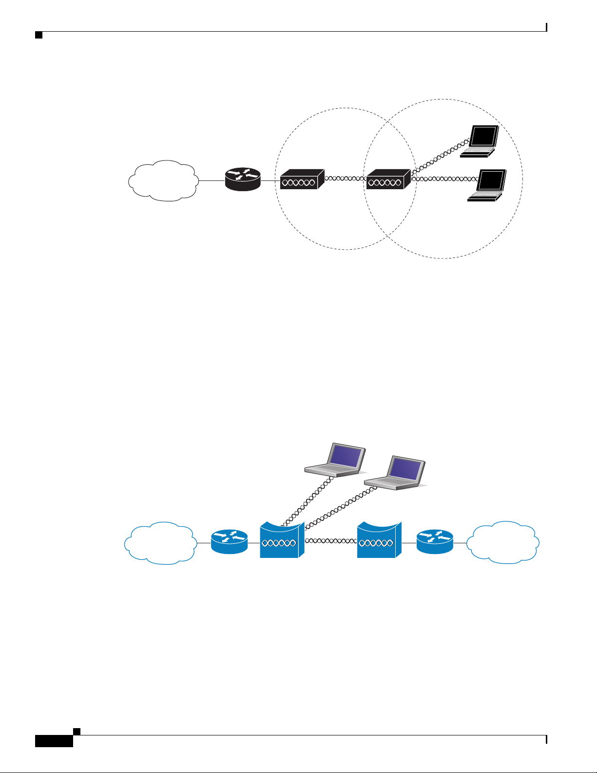
Chapter 1 Overview
Figure 1-2 Access Point as Repeater
The 1200 and 1240 access points and the 1300 access point/bridge can be configured as root or non-root
bridges. In this role, an access point establishes a wireless link with a non-root bridge. Traffic is passed
over the link to the wired LAN. Access points in root and non-root bridge roles can be configured to
accept associations from clients. Figure 1-3 shows an access point configured as a root bridge with
clients. Figure 1-4 shows two access points configured as a root and non-root bridge, both accepting
client associations. Consult the “Configuring the Role in Radio Network” section on page 6-2 for
instructions on setting up an access point as a bridge.
Figure 1-3 Access Point as a Root Bridge with Clients
1-6
Cisco IOS Software Configuration Guide for Cisco Aironet Access Points
OL-11350-01
Page 31

Chapter 1 Overview
Root bridge Non-root bridge
135446
Access point
Workgroup bridge
135448
Figure 1-4 Access Points as Root and Non-root Bridges with Clients
When wirless bridges are used in a point-to-multipoint configuration the throughput is reduced
depending on the number of non-root bridges that associate with the root bridge. The maximum
throughput is about 25 Mbps in a point to point link. The addition of three bridges to form a
point-to-multipoint network reduces the throughput to about 12.5 Mbps.
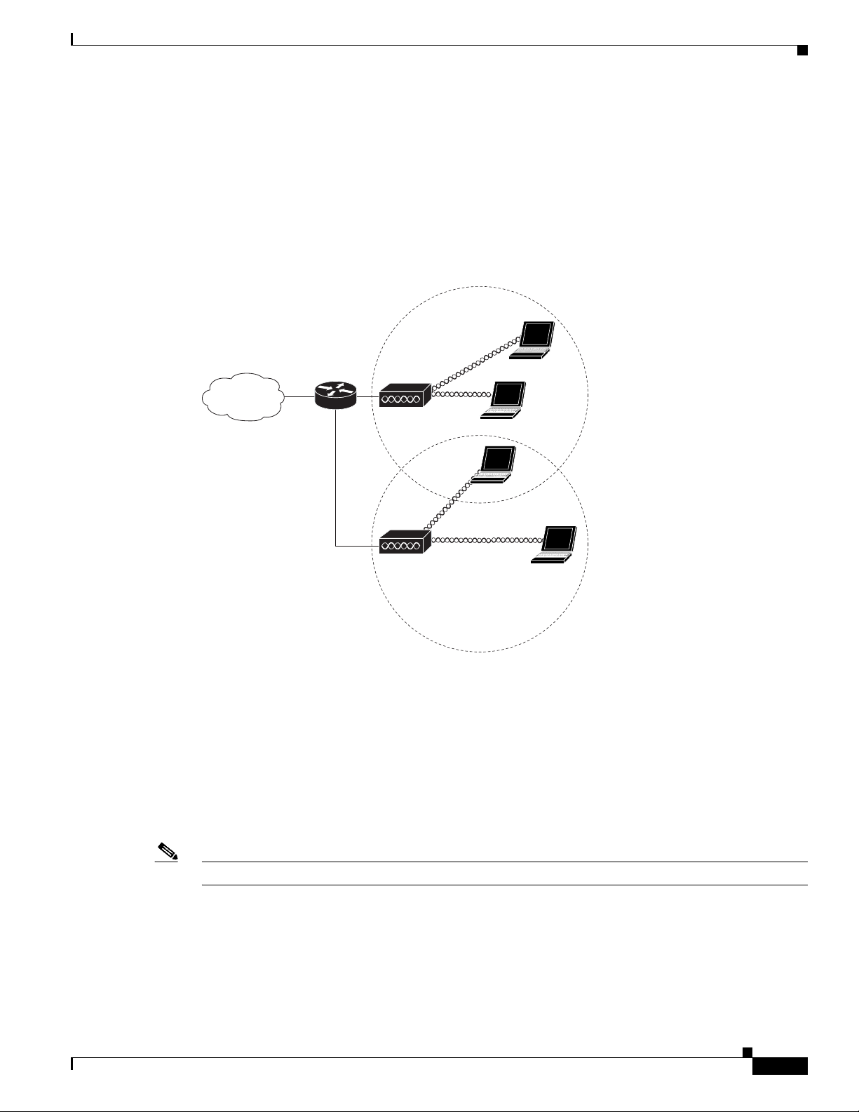
Workgroup Bridge
Network Configuration Examples
You can configure access points as workgroup bridges. In workgroup bridge mode, the unit associates
to another access point as a client and provides a network connection for the devices connected to its
Ethernet port. For example, if you need to provide wireless connectivity for a group of network printers,
you can connect the printers to a hub or to a switch, connect the hub or switch to the access point Ethernet
port, and configure the access point as a workgroup bridge. The workgroup bridge associates to an access
point on your network.
If your access point has multiple radios, either radio can function in workgroup bridge mode. When you
configure one radio interface as a workgroup bridge, the other radio interface is automatically disabled.
Figure 1-5 shows an access point configured as a workgroup bridge. Consult the “Understanding
Workgroup Bridge Mode” section on page 19-13 and the “Configuring Workgroup Bridge Mode”
section on page 19-16 for information on configuring your access point as a workgroup bridge.
Figure 1-5 Access Point as a Workgroup Bridge
OL-11350-01
Cisco IOS Software Configuration Guide for Cisco Aironet Access Points
1-7
Page 32

Network Configuration Examples
Access point
135443
Central Unit in an All-Wireless Network
In an all-wireless network, an access point acts as a stand-alone root unit. The access point is not
attached to a wired LAN; it functions as a hub linking all stations together. The access point serves as
the focal point for communications, increasing the communication range of wireless users. Figure 1-6
shows an access point in an all-wireless network.
Figure 1-6 Access Point as Central Unit in All-Wireless Network
Chapter 1 Overview
1-8
Cisco IOS Software Configuration Guide for Cisco Aironet Access Points
OL-11350-01
Page 33

CHAP T ER
2
Using the Web-Browser Interface
This chapter describes the web-browser interface that you can use to configure the wireless device. The
details regarding the configuration parameters are contained in the help system. This chapter contains
these sections:
• Using the Web-Browser Interface for the First Time, page 2-3
• Using the Management Pages in the Web-Browser Interface, page 2-3
• Enabling HTTPS for Secure Browsing, page 2-5
• Using Online Help, page 2-14
• Disabling the Web-Browser Interface, page 2-15
The web-browser interface contains management pages that you use to change the wireless device
settings, upgrade firmware, and monitor and configure other wireless devices on the network.
The following parameters can be configured by using the web browser interface.
• VLAN Configuration
• SSID configuration
• VLAN-to-SSID mappings
• Gain and power settings
• Maximum reach
• Maximum throughput
• Light Extensible Authentication Protocol (LEAP) configuration (including LEAP/RADIUS server)
• Local user profiles for local LEAP server
• Encryption modes
• Wireless MAC filter
• Detect MACs for filter (capture network discovered MAC addresses and export to MAC filter list)
• Broadcast SSID
Note The wireless device web-browser interface is fully compatible with Microsoft Internet Explorer
version 5.56.0 on Windows 98, 2000, and XP platforms, and with Netscape version 7.17.0 on
Windows 98, 2000, XP, and Solaris platforms.
OL-11350-01
Cisco IOS Software Configuration Guide for Cisco Aironet Access Points
2-1
Page 34

Chapter 2 Using the Web-Browser Interface
Note Avoid using both the CLI and the web-browser interfaces to configure the wireless device. If you
configure the wireless device using the CLI, the web-browser interface might display an inaccurate
interpretation of the configuration. However, the inaccuracy does not necessarily mean that the wireless
device is misconfigured.
2-2
Cisco IOS Software Configuration Guide for Cisco Aironet Access Points
OL-11350-01
Page 35

Chapter 2 Using the Web-Browser Interface
Using the Web-Browser Interface for the First Time
Using the Web-Browser Interface for the First Time
Use the wireless device’s IP address to browse to the management system. See the “Obtaining and
Assigning an IP Address” section on page 4-4 for instructions on assigning an IP address to the wireless
device. Follow these steps to begin using the web-browser interface:
Step 1 Start the browser.
Step 2 Enter the wireless device’s IP address in the browser Location field (Netscape Communicator) or
Address field (Internet Explorer) and press Enter. The Summary StatusHome page appears.
Using the Management Pages in the Web-Browser Interface
The system management pages use consistent techniques to present and save configuration information.
A navigation bar is on the left side of the page, and configuration action buttons appear at the bottom.
You use the navigation bar to browse to other management pages, and you use the configuration action
buttons to save or cancel changes to the configuration.
Note It is important to remember that clicking your web-browser’s Back button returns you to the previous
page without saving any changes you have made. Clicking Cancel cancels any changes you made on the
page and keeps you on that page. Changes are only applied when you click Apply.
Figure 2-1 shows the web-browser interface home page.
Figure 2-1 Web-Browser Interface Home Page
OL-11350-01
Cisco IOS Software Configuration Guide for Cisco Aironet Access Points
2-3
Page 36

Using the Management Pages in the Web-Browser Interface
Using Action Buttons
Chapter 2 Using the Web-Browser Interface
Table 2-1 lists the page links and buttons that appear on most management pages.
Table 2-1 Common Buttons on Management Pages
Button/Link Description
Navigation Links
Home Displays wireless device status page with information on the number of radio
devices associated to the wireless device, the status of the Ethernet and radio
interfaces, and a list of recent wireless device activity.
Express Setup Displays the Express Setup page that includes basic settings such as system
name, IP address, and role in radio network.
Express Security Displays the Express Security page that you use to create SSID and assign
security settings to them.
Network Map Displays a list of infrastructure devices on your wireless LAN.
Association Displays a list of all devices on your wireless LAN, listing their system names,
network roles, and parent-client relationships.
Network Interfaces Displays status and statistics for the Ethernet and radio interfaces and provides
links to configuration pages for each interface.
Security Displays a summary of security settings and provides links to security
configuration pages.
Services Displays status for several wireless device features and links to configuration
pages for Telnet/SSH, CDP, domain name server, filters, QoS, SNMP, SNTP,
and VLANs.
Wireless Services Displays a summary of wireless services used with CCKM and provides links
to WDS configuration pages.
2-4
Cisco IOS Software Configuration Guide for Cisco Aironet Access Points
OL-11350-01
Page 37

Chapter 2 Using the Web-Browser Interface
Table 2-1 Common Buttons on Management Pages (continued)
Button/Link Description
System Software Displays the version number of the firmware that the wireless device is
running and provides links to configuration pages for upgrading and managing
firmware.
Event Log Displays the wireless device event log and provides links to configuration
pages where you can select events to be included in traps, set event severity
levels, and set notification methods.
Configuration Action Buttons
Apply Saves changes made on the page and remains on the page.
Refresh Updates status information or statistics displayed on a page.
Cancel Discards changes to the page and remains on the page.
Back Discards any changes made to the page and returns to the previous page.
Character Restrictions in Entry Fields
Enabling HTTPS for Secure Browsing
Because the 1200 series access point uses Cisco IOS software, tThere are certain characters that you
cannot use in the entry fields on the web-browser interface. You cannot use these characters in entry
fields:
“
]
+
/
Tab
Trailing space
Enabling HTTPS for Secure Browsing
You can protect communication with the access point web-browser interface by enabling HTTPS.
HTTPS protects HTTP browser sessions by using the Secure Socket Layer (SSL) protocol.
Note When you enable HTTPS, your browser might lose its connection to the access point. If you lose the
connection, change the URL in your browser’s address line from http://ip_address to https://ip_address
and log into the access point again.
OL-11350-01
Note When you enable HTTPS, most browsers prompt you for approval each time you browse to a device that
does not have a fully qualified domain name (FQDN). To avoid the approval prompts, complete Step 2
through Step 9 in these instructions to create an FQDN for the access point. However, if you do not want
to create an FQDN, skip to Step 10.
Cisco IOS Software Configuration Guide for Cisco Aironet Access Points
2-5
Page 38

Enabling HTTPS for Secure Browsing
Follow these steps to create an FQDN and enable HTTPS:
Step 1 If your browser uses popup-blocking software, disable the popup-blocking feature.
Step 2 Browse to the Express Setup page. Figure 2-2 shows the Express Setup page.
Figure 2-2 Express Setup Page
Chapter 2 Using the Web-Browser Interface
2-6
Step 3
Step 4 Browse to the Services – DNS page. Figure 2-3 shows the Services – DNS page.
Cisco IOS Software Configuration Guide for Cisco Aironet Access Points
Enter a name for the access point in the System Name field and click Apply.
OL-11350-01
Page 39

Chapter 2 Using the Web-Browser Interface
Figure 2-3 Services – DNS Page
Enabling HTTPS for Secure Browsing
Step 5
Step 6 In the Domain Name field, enter your company’s domain name. At Cisco Systems, for example, the
Select Enable for Domain Name System.
domain name is cisco.com.
Step 7 Enter at least one IP address for your DNS server in the Name Server IP Addresses entry fields.
Step 8 Click Apply. The access point’s FQDN is a combination of the system name and the domain name. For
example, if your system name is ap1100 and your domain name is company.com, the FQDN is
ap1100.company.com.
Step 9 Enter the FQDN on your DNS server.
Tip If you do not have a DNS server, you can register the access point’s FQDN with a dynamic DNS service.
Search the Internet for dynamic DNS to find a fee-based DNS service.
OL-11350-01
Cisco IOS Software Configuration Guide for Cisco Aironet Access Points
2-7
Page 40

Enabling HTTPS for Secure Browsing
Step 10 Browse to the Services: HTTP Web Server page. Figure 2-4 shows the HTTP Web Server page:
Figure 2-4 Services: HTTP Web Server Page
Chapter 2 Using the Web-Browser Interface
Step 11
Step 12 Enter a domain name and click Apply.
Select the Enable Secure (HTTPS) Browsing check box and click Apply.
Note Although you can enable both standard HTTP and HTTPS, Cisco recommends that you enable
one or the other.
A warning window appears stating that you will use HTTPS to browse to the access point. The window
also instructs you to change the URL that you use to browse to the access point from http to https.
Figure 2-5 shows the warning window:
Figure 2-5 HTTPS Warning Window
Step 13
Click OK. The address in your browser’s address line changes from http://ip-address to
https://ip-address.
2-8
Cisco IOS Software Configuration Guide for Cisco Aironet Access Points
OL-11350-01
Page 41

Chapter 2 Using the Web-Browser Interface
Step 14 Another warning window appears stating that the access point’s security certificate is valid but is not
from a known source. However, you can accept the certificate with confidence because the site in
question is your own access point. Figure 2-6 shows the certificate warning window:
Figure 2-6 Certificate Warning Window
Enabling HTTPS for Secure Browsing
Step 15 Click View Certificate to accept the certificate before proceeding. (To proceed without accepting the
certificate, click Ye s, and skip to Step 24 in these instructions.) Figure 2-7 shows the Certificate window.
OL-11350-01
Cisco IOS Software Configuration Guide for Cisco Aironet Access Points
2-9
Page 42

Enabling HTTPS for Secure Browsing
Figure 2-7 Certificate Window
Chapter 2 Using the Web-Browser Interface
Step 16
On the Certificate window, click Install Certificate. The Microsoft Windows Certificate Import Wizard
appears. Figure 2-8 shows the Certificate Import Wizard window.
2-10
Cisco IOS Software Configuration Guide for Cisco Aironet Access Points
OL-11350-01
Page 43

Chapter 2 Using the Web-Browser Interface
Figure 2-8 Certificate Import Wizard Window
Enabling HTTPS for Secure Browsing
Step 17
Click Next. The next window asks where you want to store the certificate. Cisco recommends that you
use the default storage area on your system. Figure 2-9 shows the window that asks about the certificate
storage area.
Figure 2-9 Certificate Storage Area Window
OL-11350-01
Step 18
Click Next to accept the default storage area. A window appears that states that you successfully
imported the certificate. Figure 2-10 shows the completion window.
Cisco IOS Software Configuration Guide for Cisco Aironet Access Points
2-11
Page 44

Enabling HTTPS for Secure Browsing
Figure 2-10 Certificate Completion Window
Chapter 2 Using the Web-Browser Interface
Step 19
Step 20
Click Finish. Windows displays a final security warning. Figure 2-11 shows the security warning.
Figure 2-11 Certificate Security Warning
Click Yes . Windows displays another window stating that the installation is successful. Figure 2-12
shows the completion window.
2-12
Cisco IOS Software Configuration Guide for Cisco Aironet Access Points
OL-11350-01
Page 45

Chapter 2 Using the Web-Browser Interface
Figure 2-12 Import Successful Window
Step 21 Click OK.
Step 22 On the Certificate window shown in Figure 2-7, which is still displayed, click OK.
Step 23 On the Security Alert window shown in Figure 2-6, click Yes .
Step 24 The access point login window appears and you must log into the access point again. The default user
name is Cisco (case-sensitive) and the default password is Cisco (case-sensitive).
CLI Configuration Example
Enabling HTTPS for Secure Browsing
This example shows the CLI commands that are equivalent to the steps listed in the “Enabling HTTPS
for Secure Browsing” section on page 2-5:
AP# configure terminal
AP(config)# hostname ap1100
AP(config)# ip domain name company.com
AP(config)# ip name-server 10.91.107.18
AP(config)# ip http secure-server
AP(config)# end
In this example, the access point system name is ap1100, the domain name is company.com, and the IP
address of the DNS server is 10.91.107.18.
For complete descriptions of the commands used in this example, consult the Cisco IOS Commands
Master List, Release 12.3. Click this link to browse to the master list of commands:
http://www.cisco.com/en/US/docs/ios/mcl/123mcl/TD-Book-Wrapper.html
Deleting an HTTPS Certificate
The access point generates a certificate automatically when you enable HTTPS. However, if you need to
change the access point’s fully qualified domain name (FQDN) or you need to add an FQDN after
enabling HTTPS, you might need to delete the certificate. Follow these steps:
Step 1 Browse to the Services: HTTP Web Server page.
OL-11350-01
Step 2 Uncheck the Enable Secure (HTTPS) Browsing check box to disable HTTPS.
Step 3 Click Delete Certificate to delete the certificate.
Step 4 Re-enable HTTPS. The access point generates a new certificate using the new FQDN.
Cisco IOS Software Configuration Guide for Cisco Aironet Access Points
2-13
Page 46

Using Online Help
Using Online Help
Click the help icon at the top of any page in the web-browser interface to display online help. Figure 2-13
shows the help and print icons.
Figure 2-13 Help and Print Icons
When a help page appears in a new browser window, use the Select a topic drop-down menu to display
the help index or instructions for common configuration tasks, such as configuring VLANs.
Changing the Location of Help Files
Cisco maintains up-to-date HTML help files for access points on the Cisco web site. By default, the
access point opens a help file on Cisco.com when you click the help button on the access point
web-browser interface. However, you can install the help files on your network so your access points can
access them there. Follow these steps to install the help files locally:
Chapter 2 Using the Web-Browser Interface
Step 1 Download the help files from the Software Center on Cisco.com:
http://www.cisco.com/cisco/software/navigator.html
Select the help files that match the software version on your access point.
Step 2 Unzip the help files on your network in a directory accessible to your access point. When you unzip the
help files, the HTML help pages are stored in a folder named according to the help version number and
access point model number.
Step 3 Browse to the Services: HTTP Web Server page in the access point web-browser interface.
Step 4 In the Default Help Root URL entry field, enter the complete path to the location where you unzipped
the help files. When you click the access point help button, the access point automatically appends the
help version number and model number to the path that you enter.
Note Do not add the help version number and device model number to the Default Help Root URL entry. The
access point automatically adds the help version and model number to the help root URL.
If you unzip the help files on your network file server at //myserver/myhelp, your Default Help Root URL
looks like this:
http://myserver/myhelp
2-14
Cisco IOS Software Configuration Guide for Cisco Aironet Access Points
OL-11350-01
Page 47

Chapter 2 Using the Web-Browser Interface
Table 2-2 shows an example help location and Help Root URL for an 1100 series access point.
Table 2-2 Example Help Root URL and Help Location
Files Unzipped at This Location Default Help Root URL Actual Location of Help Files
//myserver/myhelp http://myserver/myhelp //myserver/myhelp/123-02.JA/1100
Step 5 Click Apply.
Disabling the Web-Browser Interface
To prevent all use of the web-browser interface, select the Disable Web-Based Management check box
on the Services: HTTP-Web Server page and click Apply.
To re-enable the web-browser interface, enter this global configuration command on the access point
CLI:
ap(config)# ip http server
Disabling the Web-Browser Interface
OL-11350-01
Cisco IOS Software Configuration Guide for Cisco Aironet Access Points
2-15
Page 48

Disabling the Web-Browser Interface
Chapter 2 Using the Web-Browser Interface
2-16
Cisco IOS Software Configuration Guide for Cisco Aironet Access Points
OL-11350-01
Page 49

CHAP T ER
3
Using the Command-Line Interface
This chapter describes the Cisco IOS command-line interface (CLI) that you can use to configure the
wireless device. It contains these sections:
• Cisco IOS Command Modes, page 3-2
• Getting Help, page 3-3
• Abbreviating Commands, page 3-3
• Using no and default Forms of Commands, page 3-4
• Understanding CLI Messages, page 3-4
• Using Command History, page 3-4
• Using Editing Features, page 3-6
• Searching and Filtering Output of show and more Commands, page 3-8
• Accessing the CLI, page 3-9
OL-11350-01
Cisco IOS Software Configuration Guide for Cisco Aironet Access Points
3-1
Page 50

Cisco IOS Command Modes
Cisco IOS Command Modes
The Cisco IOS user interface is divided into many different modes. The commands available to you
depend on which mode you are currently in. Enter a question mark (?) at the system prompt to obtain a
list of commands available for each command mode.
When you start a session on the wireless device, you begin in user mode, often called user EXEC mode.
A subset of the Cisco IOS commands are available in user EXEC mode. For example, most of the user
EXEC commands are one-time commands, such as show commands, which show the current
configuration status, and clear commands, which clear counters or interfaces. The user EXEC
commands are not saved when the wireless device reboots.
To have access to all commands, you must enter privileged EXEC mode. Normally, you must enter a
password to enter privileged EXEC mode. From this mode, you must enter privileged EXEC mode
before you can enter the global configuration mode.
Using the configuration modes (global, interface, and line), you can make changes to the running
configuration. If you save the configuration, these commands are stored and used when the wireless
device reboots. To access the various configuration modes, you must start at global configuration mode.
From global configuration mode, you can enter interface configuration mode and line configuration
mode.
Tabl e 3-1 describes the main command modes, how to access each one, the prompt you see in that mode, and
how to exit the mode. The examples in the table use the host name ap.
Chapter 3 Using the Command-Line Interface
Table 3-1 Command Mode Summary
Mode Access Method Prompt Exit Method About This Mode
User EXEC Begin a session with
the wireless device.
ap>
Enter logout or quit. Use this mode to:
• Change terminal settings
• Perform basic tests
• Display system
information
Privileged EXEC While in user EXEC
mode, enter the
enable command.
Global configuration While in privileged
EXEC mode, enter
the configure
ap#
ap(config)#
Enter disable to exit. Use this mode to verify
commands. Use a password to
protect access to this mode.
To exit to privileged
EXEC mode, enter exit or
end, or press Ctrl-Z.
Use this mode to configure
parameters that apply to the
entire wireless device.
command.
Interface
configuration
While in global
configuration mode,
enter the interface
command (with a
specific interface).
ap(config-if)#
To exit to global
configuration mode, enter
exit. To return to
privileged EXEC mode,
press Ctrl-Z or enter end.
Use this mode to configure
parameters for the Ethernet
and radio interfaces. The
2.4-GHz radio is radio 0, and
the 5-GHz radio is radio 1.
3-2
Cisco IOS Software Configuration Guide for Cisco Aironet Access Points
OL-11350-01
Page 51

Chapter 3 Using the Command-Line Interface
Getting Help
You can enter a question mark (?) at the system prompt to display a list of commands available for each
command mode. You can also obtain a list of associated keywords and arguments for any command, as
shown in Table 3-2 .
Table 3-2 Help Summary
Command Purpose
help Obtains a brief description of the help system in any command mode.
abbreviated-command-entry? Obtains a list of commands that begin with a particular character string.
For example:
ap# di?
dir disable disconnect
abbreviated-command-entry<Tab > Completes a partial command name.
For example:
ap# sh conf<tab>
ap# show configuration
? Lists all commands available for a particular command mode.
For example:
ap> ?
command ? Lists the associated keywords for a command.
Getting Help
For example:
ap> show ?
command keyword ? Lists the associated arguments for a keyword.
For example:
ap(config)# cdp holdtime ?
<10-255> Length of time (in sec) that receiver must keep this packet
Abbreviating Commands
You have to enter only enough characters for the wireless device to recognize the command as unique.
This example shows how to enter the show configuration privileged EXEC command:
ap# show conf
OL-11350-01
Cisco IOS Software Configuration Guide for Cisco Aironet Access Points
3-3
Page 52

Using no and default Forms of Commands
Using no and default Forms of Commands
Most configuration commands also have a no form. In general, use the no form to disable a feature or
function or reverse the action of a command. For example, the no shutdown interface configuration
command reverses the shutdown of an interface. Use the command without the keyword no to re-enable
a disabled feature or to enable a feature that is disabled by default.
Configuration commands can also have a default form. The default form of a command returns the
command setting to its default. Most commands are disabled by default, so the default form is the same
as the no form. However, some commands are enabled by default and have variables set to certain default
values. In these cases, the default command enables the command and sets variables to their default
values.
Understanding CLI Messages
Table 3-3 lists some error messages that you might encounter while using the CLI to configure the
wireless device.
Chapter 3 Using the Command-Line Interface
Table 3-3 Common CLI Error Messages
Error Message Meaning How to Get Help
% Ambiguous command:
"show con"
% Incomplete command.
% Invalid input detected
at ‘^’ marker.
You did not enter enough characters
for the wireless device to recognize
the command.
You did not enter all the keywords or
values required by this command.
You entered the command
incorrectly. The caret (^) marks the
point of the error.
Re-enter the command followed by a question mark (?)
with a space between the command and the question
mark.
The possible keywords that you can enter with the
command are displayed.
Re-enter the command followed by a question mark (?)
with a space between the command and the question
mark.
The possible keywords that you can enter with the
command are displayed.
Enter a question mark (?) to display all the commands
that are available in this command mode.
The possible keywords that you can enter with the
command are displayed.
Using Command History
The CLI provides a history or record of commands that you have entered. This feature is particularly
useful for recalling long or complex commands or entries, including access lists. You can customize the
command history feature to suit your needs as described in these sections:
• Changing the Command History Buffer Size, page 3-5
• Recalling Commands, page 3-5
3-4
• Disabling the Command History Feature, page 3-5
Cisco IOS Software Configuration Guide for Cisco Aironet Access Points
OL-11350-01
Page 53

Chapter 3 Using the Command-Line Interface
Changing the Command History Buffer Size
By default, the wireless device records ten command lines in its history buffer. Beginning in privileged
EXEC mode, enter this command to change the number of command lines that the wireless device
records during the current terminal session:
ap# terminal history [size number-of-lines]
The range is from 0 to 256.
Beginning in line configuration mode, enter this command to configure the number of command lines
the wireless device records for all sessions on a particular line:
ap(config-line)# history [size number-of-lines]
The range is from 0 to 256.
Recalling Commands
To recall commands from the history buffer, perform one of the actions listed in Tab l e 3- 4 :
Using Command History
Table 3-4 Recalling Commands
1
Action
Press Ctrl-P or the up arrow key. Recall commands in the history buffer, beginning with the most recent command.
Press Ctrl-N or the down arrow key. Return to more recent commands in the history buffer after recalling commands
show history While in privileged EXEC mode, list the last several commands that you just
1. The arrow keys function only on ANSI-compatible terminals such as VT100s.
Result
Repeat the key sequence to recall successively older commands.
with Ctrl-P or the up arrow key. Repeat the key sequence to recall successively
more recent commands.
entered. The number of commands that are displayed is determined by the setting
of the terminal history global configuration command and history line
configuration command.
Disabling the Command History Feature
The command history feature is automatically enabled.
To disable the feature during the current terminal session, enter the terminal no history privileged
EXEC command.
To disable command history for the line, enter the no history line configuration command.
OL-11350-01
Cisco IOS Software Configuration Guide for Cisco Aironet Access Points
3-5
Page 54

Using Editing Features
Using Editing Features
This section describes the editing features that can help you manipulate the command line. It contains
these sections:
• Enabling and Disabling Editing Features, page 3-6
• Editing Commands Through Keystrokes, page 3-6
• Editing Command Lines that Wrap, page 3-7
Enabling and Disabling Editing Features
Although enhanced editing mode is automatically enabled, you can disable it.
To re-enable the enhanced editing mode for the current terminal session, enter this command in
privileged EXEC mode:
ap# terminal editing
To reconfigure a specific line to have enhanced editing mode, enter this command in line configuration
mode:
ap(config-line)# editing
Chapter 3 Using the Command-Line Interface
To globally disable enhanced editing mode, enter this command in line configuration mode:
ap(config-line)# no editing
Editing Commands Through Keystrokes
Table 3-5 shows the keystrokes that you need to edit command lines.
Table 3-5 Editing Commands Through Keystrokes
Capability Keystroke
Move around the command line to
make changes or corrections.
Recall commands from the buffer
and paste them in the command line.
The wireless device provides a buffer
with the last ten items that you
deleted.
Ctrl-B or the left arrow
key
Ctrl-F or the right arrow
key
Ctrl-A Move the cursor to the beginning of the command line.
Ctrl-E Move the cursor to the end of the command line.
Esc B Move the cursor back one word.
Esc F Move the cursor forward one word.
Ctrl-T Transpose the character to the left of the cursor with the
Ctrl-Y Recall the most recent entry in the buffer.
Esc Y Recall the next buffer entry.
1
Purpose
Move the cursor back one character.
Move the cursor forward one character.
character located at the cursor.
The buffer contains only the last 10 items that you have
deleted or cut. If you press Esc Y more than ten times, you
cycle to the first buffer entry.
3-6
Cisco IOS Software Configuration Guide for Cisco Aironet Access Points
OL-11350-01
Page 55

Chapter 3 Using the Command-Line Interface
Table 3-5 Editing Commands Through Keystrokes (continued)
Using Editing Features
Capability Keystroke
Delete entries if you make a mistake
or change your mind.
Delete or Backspace Erase the character to the left of the cursor.
Ctrl-D Delete the character at the cursor.
1
Ctrl-K Delete all characters from the cursor to the end of the
Ctrl-U or Ctrl-X Delete all characters from the cursor to the beginning of
Ctrl-W Delete the word to the left of the cursor.
Esc D Delete from the cursor to the end of the word.
Capitalize or lowercase words or
capitalize a set of letters.
Esc C Capitalize at the cursor.
Esc L Change the word at the cursor to lowercase.
Esc U Capitalize letters from the cursor to the end of the word.
Designate a particular keystroke as
Ctrl-V or Esc Q
an executable command, perhaps as a
shortcut.
Scroll down a line or screen on
displays that are longer than the
terminal screen can display.
Note The More prompt appears for
Return Scroll down one line.
Space Scroll down one screen.
output that has more lines
than can be displayed on the
terminal screen, including
show command output. You
can use the Return and
Space bar keystrokes
whenever you see the
More
prompt.
Redisplay the current command line
Ctrl-L or Ctrl-R Redisplay the current command line.
if the wireless device suddenly sends
a message to your screen.
1. The arrow keys function only on ANSI-compatible terminals such as VT100s.
Purpose
command line.
the command line.
Editing Command Lines that Wrap
You can use a wraparound feature for commands that extend beyond a single line on the screen. When
the cursor reaches the right margin, the command line shifts ten spaces to the left. You cannot see the
first ten characters of the line, but you can scroll back and check the syntax at the beginning of the
command.
To scroll back to the beginning of the command entry, press Ctrl-B or the left arrow key repeatedly. You
can also press Ctrl-A to immediately move to the beginning of the line.
Note The arrow keys function only on ANSI-compatible terminals such as VT100s.
OL-11350-01
Cisco IOS Software Configuration Guide for Cisco Aironet Access Points
3-7
Page 56

Searching and Filtering Output of show and more Commands
In this example, the access-list global configuration command entry extends beyond one line. When the
cursor first reaches the end of the line, the line is shifted ten spaces to the left and redisplayed. The dollar
sign ($) shows that the line has been scrolled to the left. Each time the cursor reaches the end of the line,
the line is again shifted ten spaces to the left.
ap(config)# access-list 101 permit tcp 131.108.2.5 255.255.255.0 131.108.1
ap(config)# $ 101 permit tcp 131.108.2.5 255.255.255.0 131.108.1.20 255.25
ap(config)# $t tcp 131.108.2.5 255.255.255.0 131.108.1.20 255.255.255.0 eq
ap(config)# $108.2.5 255.255.255.0 131.108.1.20 255.255.255.0 eq 45
After you complete the entry, press Ctrl-A to check the complete syntax before pressing the Return key
to execute the command. The dollar sign ($) appears at the end of the line to show that the line has been
scrolled to the right:
ap(config)# access-list 101 permit tcp 131.108.2.5 255.255.255.0 131.108.1$
The software assumes you have a terminal screen that is 80 columns wide. If you have a width other than
that, use the terminal width privileged EXEC command to set the width of your terminal.
Use line wrapping with the command history feature to recall and modify previous complex command
entries. For information about recalling previous command entries, see the “Editing Commands Through
Keystrokes” section on page 3-6.
Chapter 3 Using the Command-Line Interface
Searching and Filtering Output of show and more Commands
You can search and filter the output for show and more commands. This is useful when you need to sort
through large amounts of output or if you want to exclude output that you do not need to see.
To use this functionality, enter a show or more command followed by the pipe character (|), one of the
keywords begin, include, or exclude, and an expression that you want to search for or filter out:
command | {begin | include | exclude} regular-expression
Expressions are case sensitive. For example, if you enter | exclude output, the lines that contain output
are not displayed, but the lines that contain Output are displayed.
This example shows how to include in the output display only lines where the expression protocol
appears:
ap# show interfaces | include protocol
Vlan1 is up, line protocol is up
Vlan10 is up, line protocol is down
GigabitEthernet0/1 is up, line protocol is down
GigabitEthernet0/2 is up, line protocol is up
3-8
Cisco IOS Software Configuration Guide for Cisco Aironet Access Points
OL-11350-01
Page 57

Chapter 3 Using the Command-Line Interface
Accessing the CLI
You can open the wireless device’s CLI using Telnet or Secure Shell (SSH).
Opening the CLI with Telnet
Follow these steps to open the CLI with Telnet. These steps are for a PC running Microsoft Windows
with a Telnet terminal application. Check your PC operating instructions for detailed instructions for
your operating system.
Step 1 Select Start > Programs > Accessories > Telnet.
If Telnet is not listed in your Accessories menu, select Start > Run, type Tel ne t in the entry field, and
press Enter.
Step 2 When the Telnet window appears, click Connect and select Remote System.
Note In Windows 2000, the Telnet window does not contain drop-down menus. To start the Telnet
session in Windows 2000, type open followed by the wireless device’s IP address.
Accessing the CLI
Step 3 In the Host Name field, type the wireless device’s IP address and click Connect.
Step 4 At the username and password prompts, enter your administrator username and password. The default
username is Cisco, and the default password is Cisco. The default enable password is also Cisco.
Usernames and passwords are case-sensitive.
Opening the CLI with Secure Shell
Secure Shell Protocol is a protocol that provides a secure, remote connection to networking devices set
up to use it. Secure Shell (SSH) is a software package that provides secure login sessions by encrypting
the entire session. SSH features strong cryptographic authentication, strong encryption, and integrity
protection. For detailed information on SSH, visit the homepage of SSH Communications Security, Ltd.
at this URL: http://www.ssh.com/
SSH provides more security for remote connections than Telnet by providing strong encryption when a
device is authenticated. SSH versions 1 and 2 are supported in this release. See the “Configuring the
Access Point for Secure Shell” section on page 5-25 for detailed instructions on setting up the wireless
device for SSH access.
OL-11350-01
Cisco IOS Software Configuration Guide for Cisco Aironet Access Points
3-9
Page 58

Accessing the CLI
Chapter 3 Using the Command-Line Interface
3-10
Cisco IOS Software Configuration Guide for Cisco Aironet Access Points
OL-11350-01
Page 59

CHAP T ER
4
Configuring the Access Point for the First Time
This chapter describes how to configure basic settings on the wireless device for the first time. The
contents of this chapter are similar to the instructions in the quick start guide that shipped with the
wireless device. You can configure all the settings described in this chapter using the CLI, but it might
be simplest to browse to the wireless device’s web-browser interface to complete the initial configuration
and then use the CLI to enter additional settings for a more detailed configuration.
This chapter contains these sections:
• Before You Start, page 4-2
• Obtaining and Assigning an IP Address, page 4-4
• Connecting to the 1100 Series Access Point Locally, page 4-5
• Connecting to the 1130 Series Access Point Locally, page 4-6
• Connecting to the 1200, 1230, and 1240 Series Access Points Locally, page 4-6
• Connecting to the 1300 Series Access Point/Bridge Locally, page 4-7
• Default Radio Settings, page 4-8
• Assigning Basic Settings, page 4-8
• Configuring Basic Security Settings, page 4-15
• Configuring System Power Settings for 1130 and 1240 Series Access Points, page 4-27
• Using the IP Setup Utility, page 4-28
• Assigning an IP Address Using the CLI, page 4-29
• Using a Telnet Session to Access the CLI, page 4-30
• Configuring the 802.1X Supplicant, page 4-30
Note In this release, the access point radio interfaces are disabled by default.
OL-11350-01
Cisco IOS Software Configuration Guide for Cisco Aironet Access Points
4-1
Page 60

Before You Start
Before You Start
Before you install the wireless device, make sure you are using a computer connected to the same
network as the wireless device, and obtain the following information from your network administrator:
• The login and password for the access point. The default login is Cisco and the default password is
Cisco (both case sensitive)
• A system name for the wireless device
• The case-sensitive wireless service set identifier (SSID) for your radio network
• If not connected to a DHCP server, a unique IP address for the wireless device (such as
172.17.255.115)
• If the wireless device is not on the same subnet as your PC, a default gateway address and subnet
mask
• A Simple Network Management Protocol (SNMP) community name and the SNMP file attribute (if
SNMP is in use)
• If you use IPSU to find the wireless device IP address, the access point MAC address. The MAC
address can be found on the label on the bottom of the access point (such as 00164625854c).
Chapter 4 Configuring the Access Point for the First Time
Resetting the Device to Default Settings
If you need to start over during the initial setup process, you can reset the access point to factory default
settings.
Resetting to Default Settings Using the MODE Button
Follow these steps to reset the access point to factory default settings using the access point MODE
button:
Step 1 Disconnect power (the power jack for external power or the Ethernet cable for in-line power) from the
access point.
Step 2 Press and hold the MODE button while you reconnect power to the access point.
Step 3 Hold the MODE button until the Status LED turns amber (approximately 1 to 2 seconds), and release the
button. All access point settings return to factory defaults.
Resetting to Default Settings Using the GUI
Follow these steps to return to default settings using the access point GUI:
4-2
Step 1 Open your Internet browser. The web-browser interface is fully compatible with Microsoft Internet
Explorer version 6.0 on Windows 98, 2000 and XP platforms, and with Netscape version 7.0 on
Windows 98, 2000, XP, and Solaris platforms.
Step 2 Enter the wireless device’s IP address in the browser address line and press Enter. An Enter Network
Password window appears.
Step 3 Enter your username in the User Name field. The default username is Cisco.
Cisco IOS Software Configuration Guide for Cisco Aironet Access Points
OL-11350-01
Page 61

Chapter 4 Configuring the Access Point for the First Time
Step 4 Enter the wireless device password in the Password field and press Enter. The default password is Cisco.
The Summary Status page appears.
Step 5 Click System Software and the System Software screen appears.
Step 6 Click System Configuration and the System Configuration screen appears.
Step 7 Click the Reset to Defaults button to reset all settings, including the IP address, to factory defaults. To
reset all settings except the IP address to defaults, click the Reset to Defaults (Except IP) button.
Resetting to Default Settings Using the CLI
Caution You should never delete any of the system files prior to resetting defaults or reloading software.
If you want to reset the access point to its default settings and a static IP address, use the write erase or
erase /all nvram command. If you want to erase everything including the static IP address, in addition
to the above commands, use the erase and erase boot static-ipaddr static-ipmask command.
From the privileged EXEC mode, you can reset the access point/bridge configuration to factory default
values using the CLI by following these steps:
Before You Start
Step 1 Enter erase nvram: to erase all NVRAM files including the startup configuration.
Note The erase nvram command does not erase a static IP address.
Step 2 Follow the step below to erase a static IP address and subnet mask. Otherwise, go to step 3.
a. Enter write default-config.
Step 3 Enter Y when the following CLI message displays: Erasing the nvram filesystem will remove all
configuration files! Continue? [confirm].
Step 4 Enter reload when the following CLI message displays: Erase of nvram: complete. This command
reloads the operating system.
Step 5 Enter Y when the following CLI message displays: Proceed with reload? [confirm].
Caution Do not interrupt the boot process to avoid damaging the configuration file. Wait until the access
point/bridge Install Mode LED begins to blink green before continuing with CLI configuration changes.
You can also see the following CLI message when the load process has finished: Line protocal on
Interface Dot11Radio0, changed state to up.
Step 6 After the access point/bridge reboots, you can reconfigure the access point by using the Web-browser
interface if you previously assigned a static IP address, or the CLI if you did not.
The access point is configured with the factory default values including the IP address (set to receive an
IP address using DHCP). To obtain the access point/bridge’s new IP address, you can use the show
interface bvi1 CLI command.
OL-11350-01
Cisco IOS Software Configuration Guide for Cisco Aironet Access Points
4-3
Page 62

Obtaining and Assigning an IP Address
Obtaining and Assigning an IP Address
To browse to the wireless device’s Express Setup page, you must either obtain or assign the wireless
device’s IP address using one of the following methods:
• If you have an 1130AG, 1200, 1240 series access point or 1300 series access point/bridge, connect
to the access point console port and assign a static IP address. Follow the steps in the appropriate
section to connect to the device’s console port:
–
Connecting to the 1100 Series Access Point Locally, page 4-5
–
Connecting to the 1130 Series Access Point Locally, page 4-6
–
Connecting to the 1200, 1230, and 1240 Series Access Points Locally, page 4-6.
–
Connecting to the 1300 Series Access Point/Bridge Locally, page 4-7
Note In some terminal emulator applications you may need to set the Flow control parameter to
Xon/Xoff. If you are not able to console into the device with the flow control value set to none,
try changing the flow control value to Xon/Xoff.
Chapter 4 Configuring the Access Point for the First Time
• Use a DHCP server (if available) to automatically assign an IP address. You can find out the
DHCP-assigned IP address using one of the following methods:
–
If you have a 1200 series access point, connect to the wireless device console port and use the
show ip interface brief command to display the IP address. Follow the steps in the “Connecting
to the 1100 Series Access Point Locally” section on page 4-5 or in the “Connecting to the 1200,
1230, and 1240 Series Access Points Locally” section on page 4-6 to connect to the console
port.
–
Provide your network administrator with the wireless device’s Media Access Control (MAC)
address. Your network administrator will query the DHCP server using the MAC address to
identify the IP address. The access point’s MAC address is on label attached to the bottom of
the access point.
–
Use the Cisco IP Setup Utility (IPSU) to identify the assigned address. IPSU runs on most
Microsoft Windows operating systems: Windows 9x, 2000, Me, NT, and XP.
You can download IPSU from the Software Center on Cisco.com. Click this link to browse to
the Software Center:
http://www.cisco.com/cisco/software/navigator.html
Default IP Address Behavior
When you connect a 1130AG, 1200, 1240 access point, or 1300 series access point/bridge with a default
configuration to your LAN, the access point requests an IP address from your DHCP server and, if it
does not receive an address, continues to send requests indefinitely.
When you connect an 1100 series access point with a default configuration to your LAN, the 1100 series
access point makes several attempts to get an IP address from the DHCP server. If it does not receive an
address, it assigns itself the IP address 10.0.0.1 for five minutes. During this five-minute window, you
can browse to the default IP address and configure a static address. If after five minutes the access point
is not reconfigured, it discards the 10.0.0.1 address and reverts to requesting an address from the DHCP
server. If it does not receive an address, it sends requests indefinitely. If you miss the five-minute window
for browsing to the access point at 10.0.0.1, you can power-cycle the access point to repeat the process.
4-4
Cisco IOS Software Configuration Guide for Cisco Aironet Access Points
OL-11350-01
Page 63

Chapter 4 Configuring the Access Point for the First Time
Connecting to the 1100 Series Access Point Locally
The 1300 series access point/bridge assumes a radio network role of a root access point. To configure it
as a bridge, you must manually place it in install mode in order to align the antennas and establish a link.
To establish the link you must have two access point/bridges configured in the install mode. In the install
mode, one access point/bridge must be configured as a root bridge and the other a non-root bridge. To
facilitate the configuration, an automatic option is available when the access point/bridge is in the install
mode. After the wireless link is established and the bridge antennas are aligned, you take both access
point/bridges out of install mode and place them on your LAN as root and non-root bridges.
Connecting to the 1100 Series Access Point Locally
If you need to configure the access point locally (without connecting the access point to a wired LAN),
you can connect a PC to its Ethernet port using a Category 5 Ethernet cable. You can use a local
connection to the Ethernet port much as you would use a serial port connection.
Note You do not need a special crossover cable to connect your PC to the access point; you can use
either a straight-through cable or a crossover cable.
If the access point is configured with default values and it does not receive an IP address from the DHCP
server, it defaults to IP address 10.0.0.1 for five minutes. During that five minutes, you can browse to
that IP address to configure the unit. If after five minutes the unit has not been reconfigured, it discards
the 10.0.0.1 address and reverts to requesting an address from the DHCP server. If it does not receive an
address, it sends requests indefinitely. If you miss the five-minute window for browsing to the access
point at 10.0.0.1, you can power-cycle the access point to repeat the process.
Follow these steps to connect to the access point locally:
Step 1 Make sure that the PC you intend to use to configure the access point is configured with an IP address
from 10.0.0.2 to 10.0.0.10.
Step 2 Connect your PC to the access point using a Category 5 Ethernet cable. You can use either a crossover
cable or a straight-through cable.
Step 3 Power up the access point.
Step 4 Follow the steps in the “Assigning Basic Settings” section on page 4-8. If you make a mistake and need
to start over, follow the steps in the “Resetting the Device to Default Settings” section on page 4-2.
Step 5 After configuring the access point, remove the Ethernet cable from your PC and connect the access point
to your wired LAN.
Note When you connect your PC to the access point or reconnect your PC to the wired LAN, you might need
to release and renew the IP address on the PC. On most PCs, you can perform a release and renew by
rebooting your PC or by entering ipconfig /release and ipconfig /renew commands in a command
prompt window. Consult your PC operating instructions for detailed instructions.
OL-11350-01
Cisco IOS Software Configuration Guide for Cisco Aironet Access Points
4-5
Page 64

Chapter 4 Configuring the Access Point for the First Time
Connecting to the 1130 Series Access Point Locally
Connecting to the 1130 Series Access Point Locally
If you need to configure the access point locally (without connecting the access point to a wired LAN),
you can connect a PC to its console port using a DB-9 to RJ-45 serial cable. Follow these steps to open
the CLI by connecting to the access point console port:
Step 1 Open the access point cover.
Step 2 Connect a nine-pin, female DB-9 to RJ-45 serial cable to the RJ-45 serial port on the access point and
to the COM port on a computer. The Cisco part number for the DB-9 to RJ-45 serial cable is
AIR-CONCAB1200. Browse to http://www.cisco.com/go/marketplace to order a serial cable.
Step 3 Set up a terminal emulator to communicate with the access point. Use the following settings for the
terminal emulator connection: 9600 baud, 8 data bits, no parity, 1 stop bit, and no flow control.
Note If no flow control does not work, try Xon/Xoff flow control.
Connecting to the 1200, 1230, and 1240 Series Access Points Locally
If you need to configure the access point locally (without connecting the access point to a wired LAN),
you can connect a PC to its console port using a DB-9 to RJ-45 serial cable. Follow these steps to open
the CLI by connecting to the access point console port:
Step 1 Connect a nine-pin, female DB-9 to RJ-45 serial cable to the RJ-45 serial port on the access point and
to the COM port on a computer.
Note The Cisco part number for the DB-9 to RJ-45 serial cable is AIR-CONCAB1200. Browse to
http://www.cisco.com/go/marketplace to order a serial cable.
Step 2 Set up a terminal emulator to communicate with the access point. Use the following settings for the
terminal emulator connection: 9600 baud, 8 data bits, no parity, 1 stop bit, and no flow control.
Note If no flow control does not work, try Xon/Xoff flow control.
Step 3 Connect power to the access point. The access point displays the power up configuration sequence.
Step 4 When the power up sequence ends, press Enter and the access point CLI command prompt displays,
such as AP>.
4-6
Note The access point default username is Cisco and the default password is Cisco.
Cisco IOS Software Configuration Guide for Cisco Aironet Access Points
OL-11350-01
Page 65

Chapter 4 Configuring the Access Point for the First Time
Connecting to the 1300 Series Access Point/Bridge Locally
Note When your configuration changes are completed, you must remove the serial cable from the
access point.
Connecting to the 1300 Series Access Point/Bridge Locally
If you need to configure the access point/bridge locally (without connecting the access point/bridge to a
wired LAN), you can connect a PC to the Ethernet port on the long-reach power injector using a Category
5 Ethernet cable. You can use a local connection to the power injector’s Ethernet port much as you would
use a serial port connection.
Note You do not need a special crossover cable to connect your PC to the power injector; you can use either
a straight-through cable or a crossover cable.
Follow these steps to connect to the bridge locally:
Step 1 Make sure that the PC you intend to use is configured to obtain an IP address automatically, or manually
assign it an IP address within the same subnet as the access point/bridge IP address. For example, if you
assigned the access point/bridge an IP address of 10.0.0.1, assign the PC an IP address of 10.0.0.20.
Step 2 With the power cable disconnected from the power injector, connect your PC to the power injector using
a Category 5 Ethernet cable. You can use either a crossover cable or a straight-through cable.
Note Communication takes place between the power injector and the access point/bridge using
Ethernet Port 0. Do not attempt to change any of the Ethernet Port 0 settings.
Step 3 Connect the power injector to the access point/bridge using dual coaxial cables.
Step 4 Connect the power injector power cable and power up the access point/bridge.
Step 5 Follow the steps in the “Assigning Basic Settings” section on page 4-8. If you make a mistake and need
to start over, follow the steps in the “Resetting the Device to Default Settings” procedure on page 4-2.
Step 6 After configuring the access point/bridge, remove the Ethernet cable from your PC and connect the
power injector to your wired LAN.
Note When you connect your PC to the access point/bridge or reconnect your PC to the wired LAN,
you might need to release and renew the IP address on the PC. On most PCs, you can perform a
release and renew by rebooting your PC or by entering ipconfig /release and ipconfig /renew
commands in a command prompt window. Consult your PC operating instructions for detailed
instructions.
OL-11350-01
Cisco IOS Software Configuration Guide for Cisco Aironet Access Points
4-7
Page 66

Default Radio Settings
Default Radio Settings
Beginning with Cisco IOS Release 12.3(8)JA, access point radios are disabled and no default SSID is
assigned. This was done in order to prevent unauthorized users to access a customer’s wireless network
through an access point having a default SSID and no security settings. You must create an SSID before
you can enable the access point radio interfaces.
See Chapter 6, “Configuring Radio Settings” for additional information.
Assigning Basic Settings
After you determine or assign the wireless device’s IP address, you can browse to the wireless device’s
Express Setup page and perform an initial configuration:
Step 1 Open your Internet browser. The wireless device web-browser interface is fully compatible with
Microsoft Internet Explorer version 6.0 on Windows 98, 2000, XP platforms, and with Netscape version
7.0 on Windows 98, 2000, XP, and Solaris platforms.
Chapter 4 Configuring the Access Point for the First Time
Step 2 Enter the wireless device’s IP address in the browser address line and press Enter. An Enter Network
Password screen appears.
Step 3 Press Ta b to bypass the Username field and advance to the Password field.
Step 4 Enter the case-sensitive password Cisco and press Enter. The Summary Status page appears, as shown
in Figure 4-1.
4-8
Cisco IOS Software Configuration Guide for Cisco Aironet Access Points
OL-11350-01
Page 67

Chapter 4 Configuring the Access Point for the First Time
Figure 4-1 Summary Status Page
Assigning Basic Settings
OL-11350-01
Step 5
Click Express Setup. The Express Setup screen appears. Figure 4-2 and Figure 4-3 shows the Express
Setup page for the 1100 series access points. Your pages may differ depending on the access point model
and configuration you are using.
Cisco IOS Software Configuration Guide for Cisco Aironet Access Points
4-9
Page 68

Assigning Basic Settings
Chapter 4 Configuring the Access Point for the First Time
Figure 4-2 Express Setup Page for 1100 Series Access Points
4-10
Cisco IOS Software Configuration Guide for Cisco Aironet Access Points
OL-11350-01
Page 69

Chapter 4 Configuring the Access Point for the First Time
Figure 4-3 Express Setup Page for 1130, 1200, and 1240 Series Access Points
Assigning Basic Settings
Note Figure 4-3 shows the Express Setup page for an 1130 series access point. The 1200 series is similar, but
does not support the universal workgroup bridge role.
OL-11350-01
Cisco IOS Software Configuration Guide for Cisco Aironet Access Points
4-11
Page 70

Assigning Basic Settings
Chapter 4 Configuring the Access Point for the First Time
Figure 4-4 Express Setup Page for the 1300 Series Access Point/Bridge
Step 6 Enter the configuration settings you obtained from your system administrator. The configurable settings
include:
• Host Name— The host name, while not an essential setting, helps identify the wireless device on
your network. The host name appears in the titles of the management system pages.
Note You can enter up to 32 characters for the system name. However, when the wireless device
identifies itself to client devices, it uses only the first 15 characters in the system name. If it
is important for client users to distinguish between wireless devices, make sure a unique
portion of the system name appears in the first 15 characters.
Note When you change the system name, the wireless device resets the radios, causing associated
client devices to disassociate and quickly reassociate.
• Configuration Server Protocol—Click on the button that matches the network’s method of IP
address assignment.
–
DHCP—IP addresses are automatically assigned by your network’s DHCP server.
–
Static IP—The wireless device uses a static IP address that you enter in the IP address field.
4-12
Cisco IOS Software Configuration Guide for Cisco Aironet Access Points
OL-11350-01
Page 71

Chapter 4 Configuring the Access Point for the First Time
• IP Address—Use this setting to assign or change the wireless device’s IP address. If DHCP is
enabled for your network, leave this field blank.
Note If the wireless device’s IP address changes while you are configuring the wireless device using
the web-browser interface or a Telnet session over the wired LAN, you lose your connection to
the wireless device. If you lose your connection, reconnect to the wireless device using its new
IP address. Follow the steps in the “Resetting the Device to Default Settings” section on page 4-2
if you need to start over.
• IP Subnet Mask—Enter the IP subnet mask provided by your network administrator so the IP
address can be recognized on the LAN. If DHCP is enabled, leave this field blank.
• Default Gateway—Enter the default gateway IP address provided by your network administrator.
If DHCP is enabled, leave this field blank.
• Role in Radio Network—Click on the button that describes the role of the wireless device on your
network. Select Access Point (Root) if the wireless device is connected to the wired LAN. Select
Repeater (Non-Root) if it is not connected to the wired LAN.The only role supported on the Airlink
is root.
Assigning Basic Settings
–
Access Point—A root device; accepts associations from clients and bridges wireless traffic
from the clients to the wireless LAN. This setting can be applied to any access point.
–
Repeater—A non-root device; accepts associations from clients and bridges wireless traffic
from the clients to root access point connected to the wireless LAN. This setting can be applied
to any access point.
–
Root Bridge—Establishes a link with a non-root bridge. In this mode, the device also accepts
associations from clients. This setting is available only for the 1200 and 1240 series access
points.
–
Non-Root Bridge—In this mode, the device establishes a link with a root bridge. This setting
is available only for the 1200 and 1240 series access points.
–
Install Mode—Places the 1300 series access point/bridge in auto installation mode so you can
align and adjust a bridge link for optimum efficiency.
–
Workgroup Bridge—Emulates a Cisco Aironet 350 Series Workgroup Bridge. In the
Workgroup bridge mode, the access point functions as a client device that associates with a
Cisco Aironet access point or bridge. A wokgroup bridge can have have a maximum of 254
clients, presuming that no other wireless clients are associated to the root bridge or access point.
This setting is available for the 1100, 1200, and 1300 series access points.
–
Universal Workgroup Bridge—Configures the access point as a workgroup bridge capable of
associating with non-Cisco access points. This setting is available on 1130, and 1240 series
access points and 1300 series access point/bridges.
–
Scanner—Functions as a network monitoring device. In the Scanner mode, the access point
does not accept associations from clients. It continuously scans and reports wireless traffic it
detects from other wireless devices on the wireless LAN. All access points can be configured
as a scanner.
OL-11350-01
• Optimize Radio Network for—Use this setting to select either preconfigured settings for the
wireless device radio or customized settings for the wireless device radio.
–
Throughput—Maximizes the data volume handled by the wireless device, but might reduce its
range.
–
Range—Maximizes the wireless device’s range but might reduce throughput.
Cisco IOS Software Configuration Guide for Cisco Aironet Access Points
4-13
Page 72

Assigning Basic Settings
Step 7 Click Apply to save your settings.
Step 8 Click Network Interfaces to browse to the Network Interfaces Summary page.
Step 9 Click the radio interface to browse to the Network Interfaces: Radio Status page.
Step 10 Click the Settings tab to browse to the Settings page for the radio interface.
Step 11 Click Enable to enable the radio.
Step 12 Click Apply.
Chapter 4 Configuring the Access Point for the First Time
–
Custom—The wireless device uses the settings you enter on the Network Interfaces:
Radio-802.11b Settings page. Clicking Custom takes you to the Network Interfaces:
Radio-802.11b Settings page.
• Aironet Extensions—Enable this setting if there are only Cisco Aironetwireless devices on your
wireless LAN.
• SNMP Community—If your network is using SNMP, enter the SNMP Community name provided
by your network administrator and select the attributes of the SNMP data (also provided by your
network administrator).
Your wireless device is now running but probably requires additional configuring to conform to your
network’s operational and security requirements. Consult the chapters in this manual for the information
you need to complete the configuration.
Note You can restore 1100 and 1200 series access points to factory defaults by unplugging the power
jack and plugging it back in while holding down the Mode button for a few seconds, or until the
Status LED turns amber.
Default Settings on the Express Setup Page
Table 4-1 lists the default settings for the settings on the Express Setup page.
Table 4-1 Default Settings on the Express Setup Page
Setting Default
Host Name ap
Configuration Server Protocol DHCP
IP Address Assigned by DHCP by default; see the “Default IP Address
Behavior” section on page 4-4 for a description of default IP
address behavior on the access point
IP Subnet Mask Assigned by DHCP by default; if DHCP is disabled, the default
setting is 255.255.255.224
Default Gateway Assigned by DHCP by default; if DHCP is disabled, the default
setting is 0.0.0.0
SNMP Community defaultCommunity (Read-only)
Role in Radio Network (for each
radio installed)
Access point
4-14
Cisco IOS Software Configuration Guide for Cisco Aironet Access Points
OL-11350-01
Page 73

Chapter 4 Configuring the Access Point for the First Time
Table 4-1 Default Settings on the Express Setup Page (continued)
Setting Default
Optimize Radio Network for Throughput
Aironet Extensions Enable
Configuring Basic Security Settings
After you assign basic settings to the wireless device, you must configure security settings to prevent
unauthorized access to your network. Because it is a radio device, the wireless device can communicate
beyond the physical boundaries of your worksite.
Just as you use the Express Setup page to assign basic settings, you can use the Express Security page
to create unique SSIDs and assign one of four security types to them. Figure 4-5 shows the Express
Security page.
Configuring Basic Security Settings
OL-11350-01
Cisco IOS Software Configuration Guide for Cisco Aironet Access Points
4-15
Page 74

Configuring Basic Security Settings
Figure 4-5 Express Security Page
Chapter 4 Configuring the Access Point for the First Time
4-16
Cisco IOS Software Configuration Guide for Cisco Aironet Access Points
OL-11350-01
Page 75

Chapter 4 Configuring the Access Point for the First Time
Configuring Basic Security Settings
OL-11350-01
The Express Security page helps you configure basic security settings. You can use the web-browser
interface’s main Security pages to configure more advanced security settings.
Cisco IOS Software Configuration Guide for Cisco Aironet Access Points
4-17
Page 76

Configuring Basic Security Settings
Understanding Express Security Settings
The SSIDs that you create using the Express security page appear in the SSID table at the bottom of the
page. You can create up to 16 SSIDs on the wireless device. On dual-radio wireless devices, the SSIDs
that you create are enabled on both radio interfaces.
Note In Cisco IOS Release 12.4(3g)JA and 12.3(8)JEB, there is no default SSID. You must configure
an SSID before client devices can associate to the access point.
The SSID can consist of up to 32 alphanumeric, case-sensitive, characters.
The first character can not contain the following characters:
• Exclamation point (!)
• Pound sign (#)
• Semicolon (;)
The following characters are invalid and cannot be used in an SSID:
• Plus sign (+)
• Right bracket (])
Chapter 4 Configuring the Access Point for the First Time
Using VLANs
• Front slash (/)
• Quotation mark (")
• Tab
• Trailing spaces
If you use VLANs on your wireless LAN and assign SSIDs to VLANs, you can create multiple SSIDs
using any of the four security settings on the Express Security page. However, if you do not use VLANs
on your wireless LAN, the security options that you can assign to SSIDs are limited because on the
Express Security page encryption settings and authentication types are linked. Without VLANs,
encryption settings (WEP and ciphers) apply to an interface, such as the 2.4-GHz radio, and you cannot
use more than one encryption setting on an interface. For example, when you create an SSID with static
WEP with VLANs disabled, you cannot create additional SSIDs with WPA authentication because they
use different encryption settings. If you find that the security setting for an SSID conflicts with another
SSID, you can delete one or more SSIDs to eliminate the conflict.
4-18
Cisco IOS Software Configuration Guide for Cisco Aironet Access Points
OL-11350-01
Page 77

Chapter 4 Configuring the Access Point for the First Time
Express Security Types
Table 4-2 describes the four security types that you can assign to an SSID.
Table 4-2 Security Types on Express Security Setup Page
Security Type Description Security Features Enabled
No Security This is the least secure option. You
Static WEP Key This option is more secure than no
should use this option only for SSIDs
used in a public space and assign it to
a VLAN that restricts access to your
network.
security. However, static WEP keys
are vulnerable to attack. If you
configure this setting, you should
consider limiting association to the
wireless device based on MAC
address (see the “Using MAC
Address ACLs to Block or Allow
Client Association to the Access
Point” on page 16-6) or, if your
network does not have a RADIUS
server, consider using an access point
as a local authentication server (see
Chapter 9, “Configuring an Access
Point as a Local Authenticator”).
Configuring Basic Security Settings
None.
Mandatory WEP. Client devices
cannot associate using this SSID
without a WEP key that matches the
wireless device’s key.
OL-11350-01
Cisco IOS Software Configuration Guide for Cisco Aironet Access Points
4-19
Page 78

Configuring Basic Security Settings
Table 4-2 Security Types on Express Security Setup Page (continued)
Security Type Description Security Features Enabled
EAP Authentication This option enables 802.1X
Chapter 4 Configuring the Access Point for the First Time
authentication (such as LEAP, PEAP,
EAP-TLS, EAP-FAST, EAP-TTLS,
EAP-GTC, EAP-SIM, and other
802.1X/EAP based products)
This setting uses mandatory
encryption, WEP, open
authentication + EAP, network EAP
authentication, no key management,
RADIUS server authentication port
1645.
You are required to enter the IP
address and shared secret for an
authentication server on your network
(server authentication port 1645).
Because 802.1X authentication
provides dynamic encryption keys,
you do not need to enter a WEP key.
Mandatory 802.1X authentication.
Client devices that associate using
this SSID must perform 802.1X
authentication.
If radio clients are configured to
authenticate using EAP-FAST, open
authentication with EAP should also
be configured. If you don’t configure
open authentication with EAP, the
following GUI warning message
appears:
WA R NI N G:
Network EAP is used for LEAP
authentication only. If radio clients
are configured to authenticate using
EAP-FAST, Open Authentication
with EAP should also be configured.
If you are using the CLI, this warning
message appears:
WPA Wi-Fi Protected Access (WPA)
permits wireless access to users
authenticated against a database
through the services of an
authentication server, then encrypts
their IP traffic with stronger
algorithms than those used in WEP.
This setting uses encryption ciphers,
TKIP, open authentication + EAP,
network EAP authentication, key
management WPA mandatory, and
RADIUS server authentication port
1645.
As with EAP authentication, you
must enter the IP address and shared
secret for an authentication server on
your network (server authentication
port 1645).
SSID CONFIG WARNING: [SSID]:
If radio clients are using EAP-FAST,
AUTH OPEN with EAP should also
be configured.
Mandatory WPA authentication.
Client devices that associate using
this SSID must be WPA-capable.
If radio clients are configured to
authenticate using EAP-FAST, open
authentication with EAP should also
be configured. If you don’t configure
open authentication with EAP, the
following GUI warning message
appears:
WA R NI N G:
Network EAP is used for LEAP
authentication only. If radio clients
are configured to authenticate using
EAP-FAST, Open Authentication
with EAP should also be configured.
If you are using the CLI, this warning
message appears:
SSID CONFIG WARNING: [SSID]:
If radio clients are using EAP-FAST,
AUTH OPEN with EAP should also
be configured.
4-20
Cisco IOS Software Configuration Guide for Cisco Aironet Access Points
OL-11350-01
Page 79

Chapter 4 Configuring the Access Point for the First Time
Express Security Limitations
Because the Express Security page is designed for simple configuration of basic security, the options
available are a subset of the wireless device’s security capabilities. Keep these limitations in mind when
using the Express Security page:
• If the No VLAN option is selected, the static WEP key can be configured once. If you select Enable
VLAN, the static WEP key should be disabled.
• You cannot edit SSIDs. However, you can delete SSIDs and re-create them.
• You cannot assign SSIDs to specific radio interfaces. The SSIDs that you create are enabled on all
radio interfaces. To assign SSIDs to specific radio interfaces, use the Security SSID Manager page.
• You cannot configure multiple authentication servers. To configure multiple authentication servers,
use the Security Server Manager page.
• You cannot configure multiple WEP keys. To configure multiple WEP keys, use the Security
Encryption Manager page.
• You cannot assign an SSID to a VLAN that is already configured on the wireless device. To assign
an SSID to an existing VLAN, use the Security SSID Manager page.
• You cannot configure combinations of authentication types on the same SSID (for example, MAC
address authentication and EAP authentication). To configure combinations of authentication types,
use the Security SSID Manager page.
Configuring Basic Security Settings
Using the Express Security Page
Follow these steps to create an SSID using the Express Security page:
Step 1 Type the SSID in the SSID entry field. The SSID can contain up to 32 alphanumeric characters.
Step 2 To broadcast the SSID in the wireless device beacon, check the Broadcast SSID in Beacon check box.
When you broadcast the SSID, devices that do not specify an SSID can associate to the wireless device.
This is a useful option for an SSID used by guests or by client devices in a public space. If you do not
broadcast the SSID, client devices cannot associate to the wireless device unless their SSID matches this
SSID. Only one SSID can be included in the wireless device beacon.
Step 3 (Optional) Check the Enable VLAN ID check box and enter a VLAN number (1 through 4095) to assign
the SSID to a VLAN. You cannot assign an SSID to an existing VLAN.
Step 4 (Optional) Check the Native VLAN check box to mark the VLAN as the native VLAN.
Step 5 Select the security setting for the SSID. The settings are listed in order of robustness, from No Security
to WPA, which is the most secure setting. If you select EAP Authentication or WPA, enter the IP address
and shared secret for the authentication server on your network.
Note If you do not use VLANs on your wireless LAN, the security options that you can assign to multiple
SSIDs are limited. See the “Using VLANs” section on page 4-18 for details.
Step 6 Click Apply. The SSID appears in the SSID table at the bottom of the page.
OL-11350-01
Cisco IOS Software Configuration Guide for Cisco Aironet Access Points
4-21
Page 80

Configuring Basic Security Settings
CLI Configuration Examples
The examples in this section show the CLI commands that are equivalent to creating SSIDs using each
security type on the Express Security page. This section contains these example configurations:
• Example: No Security, page 4-22
• Example: Static WEP, page 4-23
• Example: EAP Authentication, page 4-24
• Example: WPA, page 4-25
Example: No Security
This example shows part of the configuration that results from using the Express Security page to create
an SSID called no_security_ssid, including the SSID in the beacon, assigning it to VLAN 10, and
selecting VLAN 10 as the native VLAN:
!
dot11 ssid no_security_ssid
authentication open
vlan 10
!
interface Dot11Radio0/1.10
encapsulation dot1Q 10 native
no ip route-cache
bridge-group 1
bridge-group 1 subscriber-loop-control
bridge-group 1 block-unknown-source
no bridge-group 1 source-learning
no bridge-group 1 unicast-flooding
bridge-group 1 spanning-disabled
!
interface Dot11Radio1/1
no ip address
no ip route-cache
!
ssid no_security_ssid
!
speed basic-6.0 9.0 basic-12.0 18.0 basic-24.0 36.0 48.0 54.0
rts threshold 2312
station-role root
!
interface Dot11Radio1/1.10
encapsulation dot1Q 10 native
no ip route-cache
bridge-group 1
bridge-group 1 subscriber-loop-control
bridge-group 1 block-unknown-source
no bridge-group 1 source-learning
no bridge-group 1 unicast-flooding
bridge-group 1 spanning-disabled
Chapter 4 Configuring the Access Point for the First Time
4-22
Cisco IOS Software Configuration Guide for Cisco Aironet Access Points
OL-11350-01
Page 81

Chapter 4 Configuring the Access Point for the First Time
Example: Static WEP
This example shows part of the configuration that results from using the Express Security page to create
an SSID called static_wep_ssid, excluding the SSID from the beacon, assigning the SSID to VLAN 20,
selecting 3 as the key slot, and entering a 128-bit key:
ssid static_wep_ssid
vlan 20
authentication open
!
interface Dot11Radio0/1
no ip address
no ip route-cache
!
encryption vlan 20 key 3 size 128bit 7 FFD518A21653687A4251AEE1230C transmit-key
encryption vlan 20 mode wep mandatory
!
speed basic-1.0 basic-2.0 basic-5.5 basic-11.0
rts threshold 2312
station-role root
bridge-group 1
bridge-group 1 subscriber-loop-control
bridge-group 1 block-unknown-source
no bridge-group 1 source-learning
no bridge-group 1 unicast-flooding
bridge-group 1 spanning-disabled
Configuring Basic Security Settings
ssid statuc_wep_ssid
!
interface Dot11Radio0/1.20
encapsulation dot1Q 20
no ip route-cache
bridge-group 20
bridge-group 20 subscriber-loop-control
bridge-group 20 block-unknown-source
no bridge-group 20 source-learning
no bridge-group 20 unicast-flooding
bridge-group 20 spanning-disabled
!
interface Dot11Radio1/1
no ip address
no ip route-cache
!
encryption vlan 20 key 3 size 128bit 7 741F07447BA1D4382450CB68F37A transmit-key
encryption vlan 20 mode wep mandatory
!
ssid static_wep_ssid
!
speed basic-6.0 9.0 basic-12.0 18.0 basic-24.0 36.0 48.0 54.0
rts threshold 2312
station-role root
bridge-group 1
bridge-group 1 subscriber-loop-control
bridge-group 1 block-unknown-source
no bridge-group 1 source-learning
no bridge-group 1 unicast-flooding
bridge-group 1 spanning-disabled
!
interface Dot11Radio1/1.20
encapsulation dot1Q 20
no ip route-cache
bridge-group 20
bridge-group 20 subscriber-loop-control
OL-11350-01
Cisco IOS Software Configuration Guide for Cisco Aironet Access Points
4-23
Page 82

Configuring Basic Security Settings
bridge-group 20 block-unknown-source
no bridge-group 20 source-learning
no bridge-group 20 unicast-flooding
bridge-group 20 spanning-disabled
Example: EAP Authentication
This example shows part of the configuration that results from using the Express Security page to create
an SSID called eap_ssid, excluding the SSID from the beacon, and assigning the SSID to VLAN 30:
Note The following warning message appears if your radio clients are using EAP-FAST and you don’t include
open authentication with EAP as part of the configuration:
SSID CONFIG WARNING: [SSID]: If radio clients are using EAP-FAST, AUTH OPEN with EAP
should also be configured.
dot11 ssid eap_ssid
vlan 30
authentication open eap eap_methods
authentication network-eap eap_methods
!
interface Dot11Radio0/1
no ip address
no ip route-cache
!
encryption vlan 30 mode wep mandatory
!
ssid eap_ssid
!
speed basic-1.0 basic-2.0 basic-5.5 basic-11.0
rts threshold 2312
station-role root
bridge-group 1
bridge-group 1 subscriber-loop-control
bridge-group 1 block-unknown-source
no bridge-group 1 source-learning
no bridge-group 1 unicast-flooding
bridge-group 1 spanning-disabled
!
interface Dot11Radio0/1.30
encapsulation dot1Q 30
no ip route-cache
bridge-group 30
bridge-group 30 subscriber-loop-control
bridge-group 30 block-unknown-source
no bridge-group 30 source-learning
no bridge-group 30 unicast-flooding
bridge-group 30 spanning-disabled
!
interface Dot11Radio0/1
no ip address
no ip route-cache
!
encryption vlan 30 mode wep mandatory
!
ssid eap_ssid
!
speed basic-6.0 9.0 basic-12.0 18.0 basic-24.0 36.0 48.0 54.0
rts threshold 2312
station-role root
Chapter 4 Configuring the Access Point for the First Time
4-24
Cisco IOS Software Configuration Guide for Cisco Aironet Access Points
OL-11350-01
Page 83

Chapter 4 Configuring the Access Point for the First Time
bridge-group 1
bridge-group 1 subscriber-loop-control
bridge-group 1 block-unknown-source
no bridge-group 1 source-learning
no bridge-group 1 unicast-flooding
bridge-group 1 spanning-disabled
!
interface Dot11Radio0/1.30
encapsulation dot1Q 30
no ip route-cache
bridge-group 30
bridge-group 30 subscriber-loop-control
bridge-group 30 block-unknown-source
no bridge-group 30 source-learning
no bridge-group 30 unicast-flooding
bridge-group 30 spanning-disabled
!
interface FastEthernet0
mtu 1500
no ip address
ip mtu 1564
no ip route-cache
duplex auto
speed auto
bridge-group 1
no bridge-group 1 source-learning
bridge-group 1 spanning-disabled
!
interface FastEthernet0.30
mtu 1500
encapsulation dot1Q 30
no ip route-cache
bridge-group 30
no bridge-group 30 source-learning
bridge-group 30 spanning-disabled
!
interface BVI1
ip address 10.91.104.91 255.255.255.192
no ip route-cache
!
ip http server
ip http help-path
http://www.cisco.com/warp/public/779/smbiz/prodconfig/help/eag/ivory/1100
ip radius source-interface BVI1
radius-server attribute 32 include-in-access-req format %h
radius-server host 10.91.104.92 auth-port 1645 acct-port 1646 key 7 091D1C5A4D5041
radius-server authorization permit missing Service-Type
radius-server vsa send accounting
bridge 1 route ip
Configuring Basic Security Settings
Example: WPA
OL-11350-01
This example shows part of the configuration that results from using the Express Security page to create
an SSID called wpa_ssid, excluding the SSID from the beacon, and assigning the SSID to VLAN 40:
ssid wpa_ssid
vlan 40
authentication open eap eap_methods
authentication network-eap eap_methods
authentication key-management wpa
!
Cisco IOS Software Configuration Guide for Cisco Aironet Access Points
4-25
Page 84

Configuring Basic Security Settings
aaa new-model
!
!
aaa group server radius rad_eap
server 10.91.104.92 auth-port 1645 acct-port 1646
!
aaa group server radius rad_mac
!
aaa group server radius rad_acct
!
aaa group server radius rad_admin
!
aaa group server tacacs+ tac_admin
!
aaa group server radius rad_pmip
!
aaa group server radius dummy
!
aaa authentication login eap_methods group rad_eap
aaa authentication login mac_methods local
aaa authorization exec default local
aaa authorization ipmobile default group rad_pmip
aaa accounting network acct_methods start-stop group rad_acct
aaa session-id common
!
!
bridge irb
!
!
interface Dot11Radio0/1
no ip address
no ip route-cache
!
encryption vlan 40 mode ciphers tkip
!
ssid wpa_ssid
!
speed basic-1.0 basic-2.0 basic-5.5 basic-11.0
rts threshold 2312
station-role root
bridge-group 1
bridge-group 1 subscriber-loop-control
bridge-group 1 block-unknown-source
no bridge-group 1 source-learning
no bridge-group 1 unicast-flooding
bridge-group 1 spanning-disabled
!
interface Dot11Radio0/1.40
encapsulation dot1Q 40
no ip route-cache
bridge-group 40
bridge-group 40 subscriber-loop-control
bridge-group 40 block-unknown-source
no bridge-group 40 source-learning
no bridge-group 40 unicast-flooding
bridge-group 40 spanning-disabled
!
ssid wpa_ssid
!
interface FastEthernet0
no ip address
no ip route-cache
duplex auto
speed auto
Chapter 4 Configuring the Access Point for the First Time
4-26
Cisco IOS Software Configuration Guide for Cisco Aironet Access Points
OL-11350-01
Page 85

Chapter 4 Configuring the Access Point for the First Time
Configuring System Power Settings for 1130 and 1240 Series Access Points
bridge-group 1
no bridge-group 1 source-learning
bridge-group 1 spanning-disabled
!
interface FastEthernet0.40
encapsulation dot1Q 40
no ip route-cache
bridge-group 40
no bridge-group 40 source-learning
bridge-group 40 spanning-disabled
Configuring System Power Settings for 1130 and 1240 Series
Access Points
The 1130 and 1240 access points disable the radio interfaces when the unit senses that the power source
to which it is connected does not provide enough power. Depending on your power source, you might
need to enter the power source type in the access point configuration. Use the System Software: System
Configuration page on the web-browser interface to select a power option. Figure 4-6 shows the System
Power Settings section of the System Configuration page.
Figure 4-6 Power Options on the System Software: System Configuration Page
Using the AC Power Adapter
If you use the AC power adapter to provide power to the 1130 or 1240 access point, you do not need to
adjust the access point configuration.
Using a Switch Capable of IEEE 802.3af Power Negotiation
If you use a switch to provide Power over Ethernet (PoE) to the 1130 or 1240 access point, and the switch
supports the IEEE 802.3af power negotiation standard, select Power Negotiation on the System
Software: System Configuration page.
Using a Switch That Does Not Support IEEE 802.3af Power Negotiation
If you use a switch to provide Power over Ethernet (PoE) to the 1130 access point, and the switch does
not support the IEEE 802.3af power negotiation standard, select Pre-Standard Compatibility on the
System Software: System Configuration page.
Cisco IOS Software Configuration Guide for Cisco Aironet Access Points
OL-11350-01
4-27
Page 86

Using the IP Setup Utility
Using a Power Injector
If you use a power injector to provide power to the 1130 or 1240 access point, select Power Injector on
the System Software: System Configuration page and enter the MAC address of the switch port to which
the access point is connected.
dot11 extension power native Command
When enabled, the dot11 extension power native shifts the power tables the radio uses from the IEEE
802.11 tables to the native power tables. The radio derives the values for this table from the
NativePowerTable and NativePowerSupportedTable of the CISCO-DOT11-1F-MIB. The Native Power
tables were designed specifically to configure powers as low as -1dBm for Cisco Aironet radios that
support these levels.
Using the IP Setup Utility
IPSU enables you to find a wireless device’s IP address when it has been assigned by a DHCP server.
This section explains how to install the utility and how to use it to find the wireless device’s IP address.
Chapter 4 Configuring the Access Point for the First Time
Note IPSU discovers the access point’s IP address only if the unit receives an address from the DHCP server
or if you set the IP address manually. By default, access points that have a console port send DHCP
requests to the DHCP server indefinitely. IPSU cannot report the IP address until the access point
receives one.
Note IPSU can be used only on the following operating systems: Windows 95, 98, NT, 2000, ME, or XP.
Tip Another simple way to find the wireless device’s IP address is to look on the Status screen in the Aironet
Client Utility on a client device associated to the wireless device.
Obtaining IPSU
IPSU is available on the Cisco web site. Click this link to browse to the Software Center on Cisco.com:
http://www.cisco.com/cisco/software/navigator.html
Using IPSU to Find the Access Point’s IP Address
If the wireless device receives an IP address from a DHCP server, you can use IPSU to find its IP address.
Because IPSU sends a reverse-ARP request based on the wireless device MAC address, you must run
IPSU from a computer on the same subnet as the wireless device. Follow these steps to find the wireless
device’s IP address:
4-28
Step 1 Double-click the IPSU icon on your computer desktop to start the utility. The IPSU screen appears (see
Figure 4-7).
Cisco IOS Software Configuration Guide for Cisco Aironet Access Points
OL-11350-01
Page 87

Chapter 4 Configuring the Access Point for the First Time
Figure 4-7 IPSU Get IP Address Screen
Assigning an IP Address Using the CLI
Step 2
Step 3 Enter the wireless device’s MAC address in the Device MAC ID field. The wireless device’s MAC
When the utility window opens, make sure the Get IP addr radio button in the Function box is selected.
address is printed on the label on the bottom of the unit. It should contain six pairs of hexadecimal digits.
Your wireless device’s MAC address might look like the following example:
000BFCFFB24E
Note The MAC address field is not case-sensitive.
Step 4 Click Get IP Address.
Step 5 When the wireless device’s IP address appears in the IP Address field, write it down.
Assigning an IP Address Using the CLI
When you connect the wireless device to the wired LAN, the wireless device links to the network using
a bridge virtual interface (BVI) that it creates automatically. Instead of tracking separate IP addresses
for the wireless device’s Ethernet and radio ports, the network uses the BVI. Refer to the “Using the
Command-Line Interface” section on page 3-1 for information on using the CLI interface.
When you assign an IP address to the wireless device using the CLI, you must assign the address to the
BVI. Beginning in privileged EXEC mode, follow these steps to assign an IP address to the wireless
device’s BVI:
OL-11350-01
Step 1
Command Purpose
configure terminal Enter global configuration mode.
Cisco IOS Software Configuration Guide for Cisco Aironet Access Points
4-29
Page 88

Chapter 4 Configuring the Access Point for the First Time
Using a Telnet Session to Access the CLI
Command Purpose
Step 2
Step 3
interface bvi1 Enter interface configuration mode for the BVI.
ip address address
mask
Assign an IP address and address mask to the BVI.
Note If you are connected to the wireless device using a
Telnet session, you lose your connection to the wireless
device when you assign a new IP address to the BVI. If
you need to continue configuring the wireless device
using Telnet, use the new IP address to open another
Telnet session to the wireless device.
Using a Telnet Session to Access the CLI
Follow these steps to access the CLI by using a Telnet session. These steps are for a PC running
Microsoft Windows with a Telnet terminal application. Check your PC operating instructions for
detailed instructions for your operating system.
Step 1 Select Start > Programs > Accessories > Telnet.
If Telnet is not listed in your Accessories menu, select Start > Run, type Tel ne t in the entry field, and
press Enter.
Step 2 When the Telnet window appears, click Connect and select Remote System.
Note In Windows 2000, the Telnet window does not contain drop-down menus. To start the Telnet
session in Windows 2000, type open followed by the wireless device’s IP address.
Step 3 In the Host Name field, type the wireless device’s IP address and click Connect.
Configuring the 802.1X Supplicant
Traditionally, the dot1x authenticator/client relationship has always been a network device and a PC
client respectively, as it was the PC user that had to authenticate to gain access to the network. However,
wireless networks introduce unique challenges to the traditional authenticator/client relationship. First,
access points can be placed in public places, inviting the possibility that they could be unplugged and
their network connection used by an outsider. Second, when a repeater access point is incorporated into
a wireless network, the repeater access point must authenticate to the root access point in the same way
as a client does.
4-30
Note The 8021X supplicant is available on 1130AG, 1240AG, and 1300 series access points. It is not available
on 1100 and 1200 series access points.
The supplicant is configured in two phases:
• Create and configure a credentials profile
• Apply the credentials to an interface or SSID
Cisco IOS Software Configuration Guide for Cisco Aironet Access Points
OL-11350-01
Page 89

Chapter 4 Configuring the Access Point for the First Time
You can complete the phases in any order, but they must be completed before the supplicant becomes
operational.
Creating a Credentials Profile
Beginning in privileged EXEC mode, follow these steps to create an 802.1X credentials profile:
Command Purpose
Step 1
Step 2
Step 3
Step 4
Step 5
Step 6
configure terminal Enter global configuration mode.
dot1x credentials profile Creates a dot1x credentials profile and enters the dot1x
anonymous-id description (Optional)—Enter the anonymous identity to be used.
description description (Optional)—Enter a description for the credentials profile
username username Enter the authentication user id.
password {0 | 7 | LINE} Enter an unencrypted password for the credentials.
Configuring the 802.1X Supplicant
credentials configuration submode.
0—An unencrypted password will follow.
Step 7
Step 8
Step 9
7—A hidden password will follow. Hidden passwords are used
when applying a previously saved configuration.
LINE—An unencrypted (clear text) password.
Note Unencrypted and clear text are the same. You can enter a
0 followed by the clear text password, or omit the 0 and
enter the clear text password.
pki-trustpoint pki-trustpoint (Optional and only used for EAP-TLS)—Enter the default
pki-trustpoint.
end Return to the privileged EXEC mode.
copy running config
(Optional) Save your entries in the configuration file.
startup-config
Use the no form of the dot1x credentials command to negate a parameter.
The following example creates a credentials profile named test with the username Cisco and a the
unencrypted password Cisco:
ap1240AG>enable
Password:xxxxxxx
ap1240AG#config terminal
Enter configuration commands, one per line. End with CTRL-Z.
ap1240AG(config)# dot1x credentials test
ap1240AG(config-dot1x-creden)#username Cisco
ap1240AG(config-dot1x-creden)#password Cisco
ap1240AG(config-dot1x-creden)#exit
ap1240AG(config)#
Applying the Credentials to an Interface or SSID
Credential profiles are applied to an interface or an SSID in the same way.
Cisco IOS Software Configuration Guide for Cisco Aironet Access Points
OL-11350-01
4-31
Page 90

Configuring the 802.1X Supplicant
Applying the Credentials Profile to the Wired Port
Beginning in the privileged EXEC mode, follow these steps to apply the credentials to the access point’s
wired port:
Command Purpose
Step 1
Step 2
Step 3
Step 4
Step 5
configure terminal Enter global configuration mode.
interface fastethernet 0 Enter the interface configuration mode for the access point’s Fast
Ethernet port.
Note You can also use interface fa0 to enter the fast Ethernet
dot1x credentials profile name] Enter the name of a previously created credentials profile.
end Return to the privileged EXEC mode
copy running config
(Optional) Save your entries in the configuration file.
startup-config
Chapter 4 Configuring the Access Point for the First Time
configuration mode.
The following example applies the credentials profile test to the access point’s Fast Ethernet port:
ap1240AG>enable
Password:xxxxxxx
ap1240AG#config terminal
Enter configuration commands, one per line. End with CTRL-Z.
ap1240AG(config)#interface fa0
ap1240AG(config-if)#dot1x credentials test
ap1240AG(config-if)#end
ap1240AG#
Applying the Credentials Profile to an SSID Used For the Uplink
If you have a repeater access point in your wireless network and are using the 802.1X supplicant on the
root access point, you must apply the 802.1X supplicant credentials to the SSID the repeater uses to
associate with and authenticate to the root access point.
Beginning in the privileged EXEC mode, follow these steps to apply the credentials to an SSID used for
the uplink:
Command Purpose
Step 1
Step 2
configure terminal Enter global configuration mode.
dot11 ssid ssid Enter the 802.11 SSID. The SSID can consist of up to 32
alphanumeric characters. SSIDs are case sensitive.
Note The first character cannot contain the !, #, or ; character.
4-32
+, ], /, ", TAB, and trailing spaces are invalid characters for
SSIDs.
Step 3
Step 4
Step 5
dot1x credentials profile Enter the name of a preconfigured credentials profile.
end Exits the dot1x credentials configuration submode
copy running config
(Optional) Save your entries in the configuration file.
startup-config
Cisco IOS Software Configuration Guide for Cisco Aironet Access Points
OL-11350-01
Page 91

Chapter 4 Configuring the Access Point for the First Time
The following example applys the credentials profile test to the ssid testap1 on a repeater access point.
repeater-ap>enable
Password:xxxxxxx
repeater-ap#config terminal
Enter configuration commands, one per line. End with CTRL-Z.
repeater-ap(config-if)#dot11 ssid testap1
repeater-ap(config-ssid)#dot1x credentials test
repeater-ap(config-ssid)#end
repeater-ap(config)
Creating and Applying EAP Method Profiles
You can optionally configure an EAP method list to enable the supplicant to recognize a particular EAP
method. See “Creating and Applying EAP Method Profiles for the 802.1X Supplicant” on page 11-17.
Configuring the 802.1X Supplicant
OL-11350-01
Cisco IOS Software Configuration Guide for Cisco Aironet Access Points
4-33
Page 92

Configuring the 802.1X Supplicant
Chapter 4 Configuring the Access Point for the First Time
4-34
Cisco IOS Software Configuration Guide for Cisco Aironet Access Points
OL-11350-01
Page 93

CHAP T ER
5
Administering the Access PointWireless Device Access
This chapter describes how to administer the wireless device. This chapter contains these sections:
• Disabling the Mode Button, page 5-2
• Preventing Unauthorized Access to Your Access Point, page 5-3
• Protecting Access to Privileged EXEC Commands, page 5-3
• Controlling Access Point Access with RADIUS, page 5-9
• Controlling Access Point Access with TACACS+, page 5-15
• Configuring Ethernet Speed and Duplex Settings, page 5-18
• Configuring the Access Point for Wireless Network Management, page 5-18
• Configuring the Access Point for Local Authentication and Authorization, page 5-19
• Configuring the Authentication Cache and Profile, page 5-20
• Configuring the Access Point to Provide DHCP Service, page 5-22
OL-11350-01
• Configuring the Access Point for Secure Shell, page 5-25
• Configuring Client ARP Caching, page 5-26
• Managing the System Time and Date, page 5-27
• Defining HTTP Access, page 5-32
• Defining HTTP Access, page 5-32
• Creating a Banner, page 5-35
• Upgrading Autonomous Cisco Aironet Access Points to Lightweight Mode, page 5-37
• Migrating to Japan W52 Domain, page 5-37
• Configuring Multiple VLAN and Rate Limiting for Point-to-Multipoint Bridging, page 5-39
Cisco IOS Software Configuration Guide for Cisco Aironet Access Points
5-1
Page 94

Disabling the Mode Button
Disabling the Mode Button
You can disable the mode button on access points having a console port by using the [no] boot
mode-button command. This command prevents password recovery and is used to prevent unauthorized
users from gaining access to the access point CLI.
Caution This command disables password recovery. If you lose the privileged EXEC mode password for the
access point after entering this command, you will need to contact the Cisco Technical Assistance Center
(TAC) to regain access to the access point CLI.
The mode button is enabled by default. Beginning in the privilege EXEC mode, follow these steps to
disable the access point’s mode button.
Command Purpose
Step 1
Step 2
Step 3
configure terminal Enter global configuration mode.
no boot mode-button Disables the access point’s mode button.
end Note It is not necessary to save the configuration.
Chapter 5 Administering the Access PointWireless Device Access
You can check the status of the mode-button by executing the show boot or show boot mode-button
commands in the privileged EXEC mode. The status does not appear in the running configuration. The
following shows a typical response to the show boot and show boot mode-button commands:
ap#show boot
BOOT path-list: flash:/c1200-k9w7-mx-v123_7_ja.20050430/c1200-k9w7-mx.v123_7_ja.20050430
Config file: flash:/config.txt
Private Config file: flash:/private-config
Enable Break: no
Manual boot:no
Mode button:on
Enable IOS break: no
HELPER path-list:
NVRAM/Config file
buffer size: 32768
ap#show boot mode-button
on
ap#
Note As long as the privileged EXEC password is known, you can restore the mode button to normal operation
using the boot mode-button command.
5-2
Cisco IOS Software Configuration Guide for Cisco Aironet Access Points
OL-11350-01
Page 95

Chapter 5 Administering the Access PointWireless Device Access
Preventing Unauthorized Access to Your Access Point
Preventing Unauthorized Access to Your Access Point
You can prevent unauthorized users from reconfiguring the wireless device and viewing configuration
information. Typically, you want network administrators to have access to the wireless device while you
restrict access to users who connect through a terminal or workstation from within the local network.
To prevent unauthorized access to the wireless device, you should configure one of these security
features:
• Username and password pairs, which are locally stored on the wireless device. These pairs
authenticate each user before that user can access the wireless device. You can also assign a specific
privilege level (read only or read/write) to each username and password pair. For more information,
see the “Configuring Username and Password Pairs” section on page 5-7. The default username is
Cisco, and the default password is Cisco. Usernames and passwords are case-sensitive.
Note Characters TAB, ?, $, +, and [ are invalid characters for passwords.
• Username and password pairs stored centrally in a database on a security server. For more
information, see the “Controlling Access Point Access with RADIUS” section on page 5-9.
Protecting Access to Privileged EXEC Commands
A simple way of providing terminal access control in your network is to use passwords and assign
privilege levels. Password protection restricts access to a network or network device. Privilege levels
define what commands users can issue after they have logged into a network device.
Note For complete syntax and usage information for the commands used in this section, refer to the Cisco IOS
Security Command Reference for Release 12.3.
This section describes how to control access to the configuration file and privileged EXEC commands.
It contains this configuration information:
• Default Password and Privilege Level Configuration, page 5-4
• Setting or Changing a Static Enable Password, page 5-4
• Protecting Enable and Enable Secret Passwords with Encryption, page 5-6
• Configuring Username and Password Pairs, page 5-7
• Configuring Multiple Privilege Levels, page 5-8
OL-11350-01
Cisco IOS Software Configuration Guide for Cisco Aironet Access Points
5-3
Page 96

Chapter 5 Administering the Access PointWireless Device Access
Protecting Access to Privileged EXEC Commands
Default Password and Privilege Level Configuration
Table 5-1 shows the default password and privilege level configuration.
Table 5-1 Default Password and Privilege Levels
Feature Default Setting
Username and password Default username is Cisco and the default password is Cisco.
Enable password and privilege level Default password is Cisco. The default is level 15 (privileged EXEC
level). The password is encrypted in the configuration file.
Enable secret password and privilege level The default enable password is Cisco. The default is level 15 (privileged
EXEC level). The password is encrypted before it is written to the
configuration file.
Line password Default password is Cisco. The password is encrypted in the configuration
file.
Setting or Changing a Static Enable Password
Step 1
Step 2
The enable password controls access to the privileged EXEC mode.
Note The no enable password global configuration command removes the enable password, but you should
use extreme care when using this command. If you remove the enable password, you are locked out of
the EXEC mode.
Beginning in privileged EXEC mode, follow these steps to set or change a static enable password:
Command Purpose
configure terminal Enter global configuration mode.
enable password password Define a new password or change an existing password for access to
privileged EXEC mode.
The default password is Cisco.
For password, specify a string from 1 to 25 alphanumeric characters. The
string cannot start with a number, is case sensitive, and allows spaces but
ignores leading spaces. It can contain the question mark (?) character if
you precede the question mark with the key combination Crtl-V when you
create the password; for example, to create the password abc?123, do this:
1. Enter abc.
2. Enter Crtl-V.
5-4
3. Enter ?123.
When the system prompts you to enter the enable password, you need not
precede the question mark with the Ctrl-V; you can simply enter abc?123
at the password prompt.
Note Characters TAB, ?, $, +, and [ are invalid characters for
passwords.
Cisco IOS Software Configuration Guide for Cisco Aironet Access Points
OL-11350-01
Page 97

Chapter 5 Administering the Access PointWireless Device Access
Command Purpose
Step 3
Step 4
Step 5
end Return to privileged EXEC mode.
show running-config Verify your entries.
copy running-config startup-config (Optional) Save your entries in the configuration file.
This example shows how to change the enable password to l1u2c3k4y5. The password is not encrypted
and provides access to level 15 (traditional privileged EXEC mode access):
AP(config)# enable password l1u2c3k4y5
Protecting Access to Privileged EXEC Commands
The enable password is not encrypted and can be read in the wireless
device configuration file.
OL-11350-01
Cisco IOS Software Configuration Guide for Cisco Aironet Access Points
5-5
Page 98

Chapter 5 Administering the Access PointWireless Device Access
Protecting Access to Privileged EXEC Commands
Protecting Enable and Enable Secret Passwords with Encryption
To provide an additional layer of security, particularly for passwords that cross the network or that are
stored on a Trivial File Transfer Protocol (TFTP) server, you can use either the enable password or
enable secret global configuration commands. Both commands accomplish the same thing; that is, you
can establish an encrypted password that users must enter to access privileged EXEC mode (the default)
or any privilege level you specify.
Cisco recommends that you use the enable secret command because it uses an improved encryption
algorithm.
If you configure the enable secret command, it takes precedence over the enable password command;
the two commands cannot be in effect simultaneously.
Beginning in privileged EXEC mode, follow these steps to configure encryption for enable and enable
secret passwords:
Command Purpose
Step 1
Step 2
configure terminal Enter global configuration mode.
enable password [level level] {password |
encryption-type encrypted-password}
Define a new password or change an existing password for
access to privileged EXEC mode.
Step 3
Step 4
Step 5
or
enable secret [level level] {password |
encryption-type encrypted-password}
or
Define a secret password, which is saved using a
nonreversible encryption method.
• (Optional) For level, the range is from 0 to 15. Level 1
is normal user EXEC mode privileges. The default level
is 15 (privileged EXEC mode privileges).
• For password, specify a string from 1 to 25
alphanumeric characters. The string cannot start with a
number, is case sensitive, and allows spaces but ignores
leading spaces. By default, no password is defined.
• (Optional) For encryption-type, only type 5, a Cisco
proprietary encryption algorithm, is available. If you
specify an encryption type, you must provide an
encrypted password—an encrypted password you copy
from another access pointwireless device configuration.
Note If you specify an encryption type and then enter a
clear text password, you can not re-enter privileged
EXEC mode. You cannot recover a lost encrypted
password by any method.
service password-encryption (Optional) Encrypt the password when the password is
defined or when the configuration is written.
Encryption prevents the password from being readable in the
configuration file.
end Return to privileged EXEC mode.
copy running-config startup-config (Optional) Save your entries in the configuration file.
5-6
Cisco IOS Software Configuration Guide for Cisco Aironet Access Points
OL-11350-01
Page 99

Chapter 5 Administering the Access PointWireless Device Access
If both the enable and enable secret passwords are defined, users must enter the enable secret password.
Use the level keyword to define a password for a specific privilege level. After you specify the level and
set a password, give the password only to users who need to have access at this level. Use the privilege
level global configuration command to specify commands accessible at various levels. For more
information, see the “Configuring Multiple Privilege Levels” section on page 5-8.
If you enable password encryption, it applies to all passwords including username passwords,
authentication key passwords, the privileged command password, and console and virtual terminal line
passwords.
To remove a password and level, use the no enable password [level level] or no enable secret [level
level] global configuration command. To disable password encryption, use the no service
password-encryption global configuration command.
This example shows how to configure the encrypted password $1$FaD0$Xyti5Rkls3LoyxzS8 for
privilege level 2:
AP(config)# enable secret level 2 5 $1$FaD0$Xyti5Rkls3LoyxzS8
Configuring Username and Password Pairs
Protecting Access to Privileged EXEC Commands
Step 1
Step 2
Step 3
Step 4
Step 5
Step 6
You can configure username and password pairs, which are locally stored on the wireless device. These
pairs are assigned to lines or interfaces and authenticate each user before that user can access the wireless
device. If you have defined privilege levels, you can also assign a specific privilege level (with
associated rights and privileges) to each username and password pair.
Beginning in privileged EXEC mode, follow these steps to establish a username-based authentication
system that requests a login username and a password:
Command Purpose
configure terminal Enter global configuration mode.
username name [privilege level]
{password encryption-type password}
Enter the username, privilege level, and password for each user.
• For name, specify the user ID as one word. Spaces and quotation
marks are not allowed.
• (Optional) For level, specify the privilege level the user has after
gaining access. The range is 0 to 15. Level 15 gives privileged EXEC
mode access. Level 1 gives user EXEC mode access.
• For encryption-type, enter 0 to specify that an unencrypted password
will follow. Enter 7 to specify that a hidden password will follow.
• For password, specify the password the user must enter to gain access
to the wireless device. The password must be from 1 to 25 characters,
can contain embedded spaces, and must be the last option specified
in the username command.
login local Enable local password checking at login time. Authentication is based on
the username specified in Step 2.
end Return to privileged EXEC mode.
show running-config Verify your entries.
copy running-config startup-config (Optional) Save your entries in the configuration file.
OL-11350-01
Cisco IOS Software Configuration Guide for Cisco Aironet Access Points
5-7
Page 100

Protecting Access to Privileged EXEC Commands
To disable username authentication for a specific user, use the no username name global configuration
command.
To disable password checking and allow connections without a password, use the no login line
configuration command.
Note You must have at least one username configured and you must have login local set to open a
Telnet session to the wireless device. If you enter no username for the only username, you can
be locked out of the wireless device.
Configuring Multiple Privilege Levels
By default, Cisco IOS software has two modes of password security: user EXEC and privileged EXEC.
You can configure up to 16 hierarchical levels of commands for each mode. By configuring multiple
passwords, you can allow different sets of users to have access to specified commands.
For example, if you want many users to have access to the clear line command, you can assign it
level 2 security and distribute the level 2 password fairly widely. But if you want more restricted access
to the configure command, you can assign it level 3 security and distribute that password to a more
restricted group of users.
This section includes this configuration information:
• Setting the Privilege Level for a Command, page 5-8
Chapter 5 Administering the Access PointWireless Device Access
• Logging Into and Exiting a Privilege Level, page 5-9
Setting the Privilege Level for a Command
Beginning in privileged EXEC mode, follow these steps to set the privilege level for a command mode:
Command Purpose
Step 1
Step 2
configure terminal Enter global configuration mode.
privilege mode level level command Set the privilege level for a command.
• For mode, enter configure for global configuration mode, exec for
EXEC mode, interface for interface configuration mode, or line for
line configuration mode.
• For level, the range is from 0 to 15. Level 1 is for normal user EXEC
mode privileges. Level 15 is the level of access permitted by the
enable password.
• For command, specify the command to which you want to restrict
access.
5-8
Cisco IOS Software Configuration Guide for Cisco Aironet Access Points
OL-11350-01
 Loading...