

Circutor Line-M-4IO-T, Line-TCPRS1, Line-M-4IO-A, Line-M-EXT-PS, Line-M-4IO-R User guide
...Page 1
Expansion modules for the line-CVM and
line-EDS devices
INSTRUCTION MANUAL
(M239B01-03-21A)
Page 2

line-M
2
Instruction Manual
Page 3
line-M
SAFETY PRECAUTIONS
Follow the warnings described in this manual with the symbols shown below.
DANGER
Warns of a risk, which could result in personal injury or material damage.
ATTENTION
Indicates that special attention should be paid to a specific point.
If you must handle the unit for its installation, start-up or maintenance, the following should be
taken into consideration:
Incorrect handling or installation of the unit may result in injury to personnel as well as damage to the
unit. In particular, handling with voltages applied may result in electric shock, which may cause death
or serious injury to personnel. Defective installation or maintenance may also lead to the risk of fire.
Read the manual carefully prior to connecting the unit. Follow all installation and maintenance instructions throughout the unit’s working life. Pay special attention to the installation standards of the
National Electrical Code.
Refer to the instruction manual before using the unit
In this manual, if the instructions marked with this symbol are not respected or carried out correctly, it can result
in injury or damage to the unit and /or installations.
CIRCUTOR, SA reserves the right to modify features or the product manual without prior notification.
DISCLAIMER
CIRCUTOR, SA reserves the right to make modifications to the device or the unit specifications set
out in this instruction manual without prior notice.
CIRCUTOR, SA on its web site, supplies its customers with the latest versions of the device specifications and the most updated manuals.
www.circutor.com
CIRCUTOR, recommends using the original cables and accessories that are supplied
with the device.
Instruction Manual
3
Page 4

line-M
CONTENTS
SAFETY PRECAUTIONS .........................................................................................................................................................3
DISCLAIMER .......................................................................................................................................................................... 3
CONTENTS ............................................................................................................................................................................. 4
REVISION LOG .......................................................................................................................................................................7
SYMBOLS ...............................................................................................................................................................................7
1 VERIFICATION UPON RECEPTION ....................................................................................................................................8
2 PRODUCT DESCRIPTION .................................................................................................................................................8
3. INSTALLATION OF THE DEVICE ..................................................................................................................................... 10
3.1.- PRELIMINARY RECOMMENDATIONS ...................................................................................................................... 10
3.2.- INSTALLATION ........................................................................................................................................................11
3.3.- PANEL ADAPTER 72 x 72 mm ................................................................................................................................ 12
4. LINEM4IOR ............................................................................................................................................................... 14
4.1.- DEVICE TERMINALS ............................................................................................................................................... 14
4.2. - CONNECTION DIAGRAM ........................................................................................................................................ 15
4.3 .- LED INDICATORS ................................................................................................................................................... 16
4.4.- CONFIGURATION line-M-4IO-R ............................................................................................................................ 17
4.4.1.- CONFIGURATION OF DIGITAL INPUTS 1 ... 4 ................................................................................................... 18
4.4.2.- CONFIGURATION OF RELAY OUTPUTS 1 ... 4 ..................................................................................................20
4.5.- MODBUS MEMORY MAP line-M-4IO-R ................................................................................................................. 29
4.5.1.- INPUT AND OUTPUT STATUS .........................................................................................................................29
4.5.2.- PULSE METERS .............................................................................................................................................29
4.5.3.- ALARMS .........................................................................................................................................................30
4.5.4.- DEVICE CONFIGURATION VARIABLES ............................................................................................................30
4.6.- TECHNICAL FEATURES: line-M-4IO-R ...................................................................................................................36
5 . LINEM4IOT .............................................................................................................................................................38
5.1.- DEVICE TERMINALS ...............................................................................................................................................38
5.2. - CONNECTION DIAGRAM ........................................................................................................................................39
5.3 .- LED INDICATORS ...................................................................................................................................................40
5.4.- CONFIGURATION line-M-4IO-T ............................................................................................................................ 41
5.4.1.- CONFIGURATION OF DIGITAL INPUTS 1 ... 4 ...................................................................................................42
5.4.2.- CONFIGURATION OF TRANSISTOR OUTPUTS 1 ... 4 .......................................................................................42
5.5.- MODBUS MEMORY MAP line-M-4IO-T .................................................................................................................42
5.5.1.- INPUT AND OUTPUT STATUS .........................................................................................................................42
5.5.2.- PULSE METERS ..............................................................................................................................................42
5.5.3.- ALARMS .........................................................................................................................................................42
5.5.4.- DEVICE CONFIGURATION VARIABLES ............................................................................................................42
5.6.- TECHNICAL FEATURES: line-M-4IO-T ................................................................................................................... 43
6 . LINEM4IOA .............................................................................................................................................................. 44
6.1.- DEVICE TERMINALS ...............................................................................................................................................44
6.2. - CONNECTION DIAGRAM ........................................................................................................................................45
6.3 .- LED INDICATORS...................................................................................................................................................45
6.4.- CONFIGURATION Line-M-410-A ...........................................................................................................................47
6.4.1.- CONFIGURATION OF ANALOGUE INPUTS 1 ... 4 .............................................................................................. 48
6.4.2.- CONFIGURATION OF ANALOGUE OUTPUTS 1 ... 4 ..........................................................................................50
6.5.- MODBUS MEMORY MAP line-M-4IO-A ................................................................................................................. 51
6.5.1.- ANALOGUE INPUT ........................................................................................................................................... 51
6.5.2.- DEVICE CONFIGURATION VARIABLES ............................................................................................................ 51
6.6.- TECHNICAL FEATURES: line-M-4IO-A ...................................................................................................................55
7. LINEM4IORV .............................................................................................................................................................57
7.1.- DEVICE TERMINALS ................................................................................................................................................ 57
7.2. - CONNECTION DIAGRAM .........................................................................................................................................58
7.3 .- LED INDICATORS ...................................................................................................................................................59
7.4.- CONFIGURATION line-M-4IO-RV .......................................................................................................................... 60
7.4.1.- CONFIGURATION OF DIGITAL INPUTS 1 ... 4 .................................................................................................... 61
7.4.2.- CONFIGURATION OF RELAY OUTPUTS 1 ... 4 .................................................................................................. 61
7.5.- MODBUS MEMORY MAP Line-M-410-RV ............................................................................................................. 61
7.5.1.- INPUT AND OUTPUT STATUS ......................................................................................................................... 61
7.5.2.- ALARMS ......................................................................................................................................................... 61
7.5.3.- DEVICE CONFIGURATION VARIABLES ............................................................................................................. 61
4
Instruction Manual
Page 5

line-M
7.6.- TECHNICAL FEATURES: Line-M-410-RV ...............................................................................................................62
8. LINEMEXTPS ............................................................................................................................................................ 64
8.1.- INSTALLATION ........................................................................................................................................................64
8.2.- DEVICE TERMINALS ................................................................................................................................................65
8.3. - CONNECTION DIAGRAM .........................................................................................................................................65
8.3.1.- MAXIMUM CONNECTION.................................................................................................................................65
8.3.2.- MULTIPLE CONNECTION Line-M-EXT-PS ..................................................................................................... 66
8.4. - LED INDICATORS .................................................................................................................................................. 66
8.5. - TECHNICAL FEATURES: Line-M-EXT-PS ..............................................................................................................67
9. LINEM3G ................................................................................................................................................................... 68
9.1.- INSTALLATION OF THE SIM CARD ......................................................................................................................... 68
9.2.- LED INDICATORS ................................................................................................................................................... 69
9.3.- COMMUNICATIONS ................................................................................................................................................70
9.3.1.- USAGE ENVIRONMENT AND HEALTH ..............................................................................................................70
9.3.2.- 3G COMMUNICATIONS ....................................................................................................................................70
9.4.- TECHNICAL FEATURES: line-M-3G ........................................................................................................................ 71
10. LINETCPRS1 ...............................................................................................................................................................73
10.1.- INSTALLATION ......................................................................................................................................................73
10.2.- DEVICE TERMINALS ............................................................................................................................................. 73
10.3.- LED INDICATORS .................................................................................................................................................. 74
10.4.- COMMUNICATIONS ..............................................................................................................................................75
10.4.1.- USAGE ENVIRONMENT AND HEALTH ............................................................................................................75
10.4.2.- Wi-Fi COMMUNICATIONS ..............................................................................................................................75
10.4.3.- Bluetooth® COMMUNICATIONS .................................................................................................................... 75
10.4.4.- CONFIGURATION WEBSITE ............................................................................................................................ 75
10.4.5.- MOBILE APP ..................................................................................................................................................78
10.5.- TECHNICAL FEATURES: line-TCPRS1 ..................................................................................................................79
11. LINEM20I .................................................................................................................................................................. 81
11.1.- INSTALLATION .......................................................................................................................................................81
11.2.- DEVICE TERMINALS .............................................................................................................................................. 81
11.3.- CONNECTION DIAGRAM ........................................................................................................................................82
11.4.- LED INDICATORS .................................................................................................................................................. 83
11.5.- MODBUS MEMORY MAP ...................................................................................................................................... 83
11.5.1.- DIGITAL INPUTS ........................................................................................................................................... 83
11.5.2.- PULSE METERS .............................................................................................................................................84
11.5.3.- OTHER DEVICE PARAMETERS ...................................................................................................................... 85
11.5.4.- DEVICE CONFIGURATION VARIABLES .......................................................................................................... 85
11.6.- TECHNICAL FEATURES: line-M-20I .................................................................................................................... 86
12. LINELM20ITCP KIT .................................................................................................................................................. 88
12.1.- INSTALLATION ..................................................................................................................................................... 88
12.2.- DEVICE TERMINALS ............................................................................................................................................ 89
12.3.- CONNECTION DIAGRAM ...................................................................................................................................... 90
12.4.- LED INDICATORS .................................................................................................................................................. 91
12.5.- MODBUS MEMORY MAP ......................................................................................................................................92
12.6.- COMMUNICATIONS ...............................................................................................................................................92
12.6.1.- USAGE ENVIRONMENT AND HEALTH ............................................................................................................. 92
12.6.2.- Wi-Fi COMMUNICATIONS...............................................................................................................................92
12.6.3.- Bluetooth® COMMUNICATIONS ....................................................................................................................92
12.6.4.- CONFIGURATION WEBSITE ............................................................................................................................93
12.6.5.- MOBILE APP ..................................................................................................................................................93
12.7.- TECHNICAL FEATURES: line-LM20I-TCP kit ........................................................................................................93
13. LINELM40ITCP KIT .................................................................................................................................................. 96
13.1.- INSTALLATION ..................................................................................................................................................... 96
13.2.- DEVICE TERMINALS .............................................................................................................................................97
13.3.- CONNECTION DIAGRAM ...................................................................................................................................... 98
13.4.- LED INDICATORS ................................................................................................................................................. 99
13.5.- MODBUS MEMORY MAP ....................................................................................................................................100
13.6.- COMMUNICATIONS .............................................................................................................................................100
13.6.1.- USAGE ENVIRONMENT AND HEALTH ...........................................................................................................100
13.6.2.- Wi-Fi COMMUNICATIONS ............................................................................................................................100
13.6.3.- Bluetooth® COMMUNICATIONS ..................................................................................................................100
13.6.4.- CONFIGURATION WEBSITE........................................................................................................................... 101
Instruction Manual
5
Page 6

line-M
13.6.5.- MOBILE APP .................................................................................................................................................101
13.7.- TECHNICAL FEATURES: line-LM40I-TCP kit ........................................................................................................101
14. MAINTENANCE AND TECHNICAL SERVICE ................................................................................................................ 104
15 . GUARANTEE .............................................................................................................................................................. 104
16. CE CERTIFICATE ........................................................................................................................................................ 105
ANNEX A. CONFIGURATION MENUS................................................................................................................................108
A.1.- line-M-4IO-R, line-M-4IO-T and line-M-4IO-RV ................................................................................................108
A.2.- line-M-4IO-A ........................................................................................................................................................110
6
Instruction Manual
Page 7
line-M
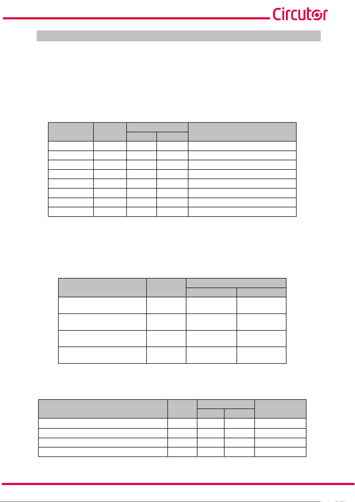
REVISION LOG
Date Revision Description
03/20 M239B01-03-19A First Version
06/20 M239B01-03-20A
11/20 M239B01-03-20B
05/21 M239B01-03-21A
Table 1: Revision log.
Changes in the following sections:
2.- 3.2. - 4.2. - 4.4.1.1. - 4.5.4.1. - 4.6. - 5.2. - 5.6. - 6.6. - 7.2. - 7.6. -
9. - 10. - 11.- 14.
Changes in the following sections:
2.- 9.4.- 10. - 10.2. - 10.3. - 10.4.5.- 11.- 11.1.- 12. - 13.
Changes in the following sections:
10.
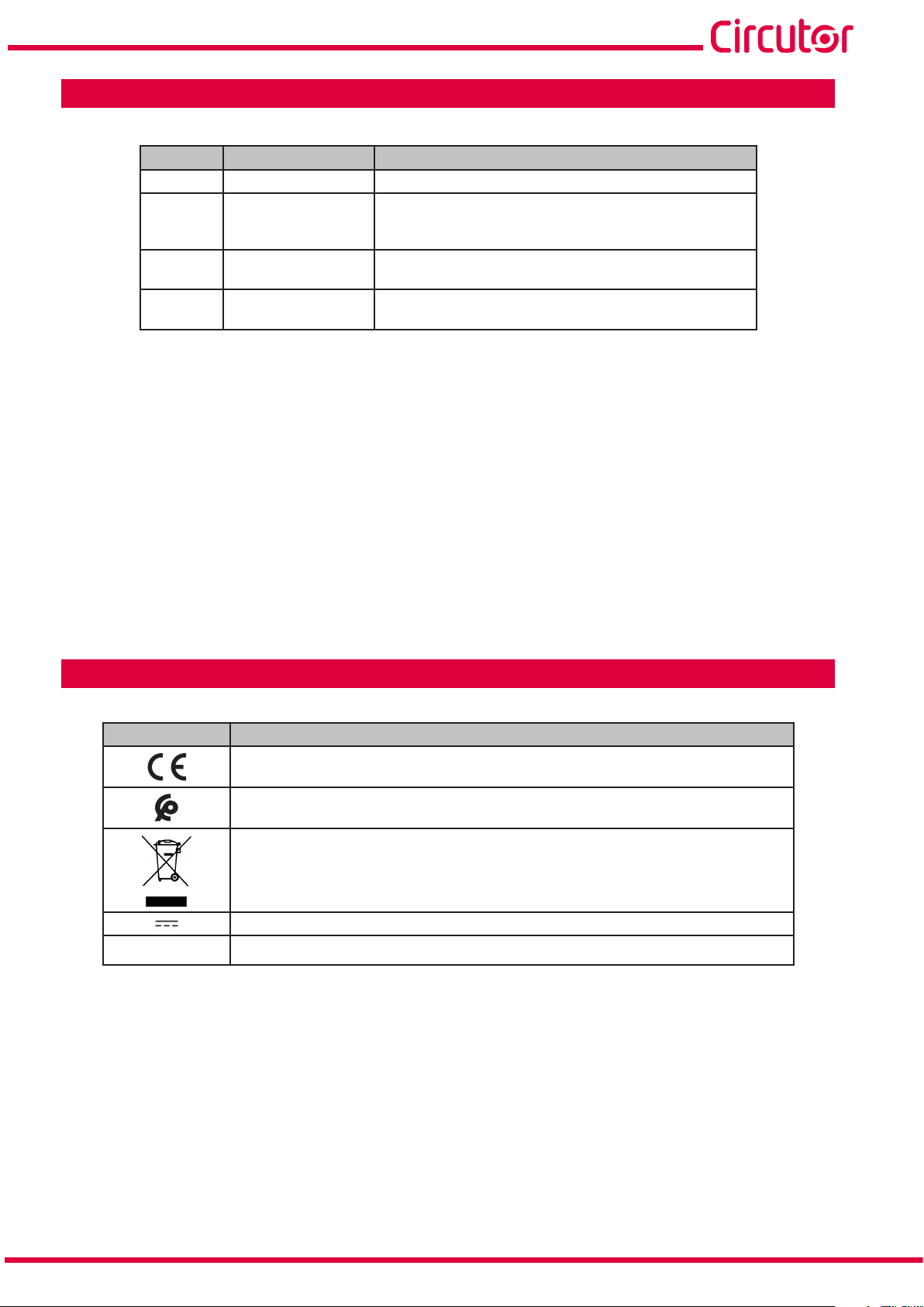
SYMBOLS
Table 2: Symbols.
Symbol Description
In accordance with the relevant European directive.
In accordance with the CMiM directive.
Device covered by European Directive 2012/19/EC. At the end of its useful life, do not leave the
device in a household refuse bin. Follow local regulations on electronic equipment recycling.
Direct current.
~
Alternating current.
Note: The images of the devices are for illustrative purposes only and may differ from the original
device.
Instruction Manual
7
Page 8
1 VERIFICATION UPON RECEPTION
Upon reception of the device check the following points:
a) The device meets the specifications described in your order.
b) The device has not suffered any damage during transport.
c) Perform an external visual inspection of the device prior to switching it on.
d) Check that it has been delivered with the following:
- An installation guide
- An expansion connector.
- 4 clamping clips.
If any problem is noticed upon reception, immediately contact the transport company and/or CIRCUTOR's after-sales service
line-M
2 PRODUCT DESCRIPTION
The line-CVM and line-EDS devices have expansion modules to increase their performance.
The expansion modules available are:
line-M-4IO-R, expansion module with 4 digital inputs and 4 relay outputs.
line-M-4IO-T expansion module, with 4 digital inputs and 4 transistor outputs.
line-M-4IO-A, expansion module with 4 analogue inputs and outputs.
line-M-4IO-RV, expansion module with 4 digital inputs (230 V~) and 4 relay outputs.
Line-M-EXT-PS, power adapter module.
line-M-3G, expansion module that adds 3G connectivity to line-EDS devices.
line-M-20I, hub with 20 digital inputs.
line-TCPRS1, RS-485/RS-232 to TCP/IP converter.
line-LM20I-TCP kit, hub with 20 digital inputs that includes an RS-485/RS-232 to TCP/IP con-
verter.
line-LM40I-TCP kit, hub with 40 digital inputs that includes an RS-485/RS-232 to TCP/IP con-
verter.
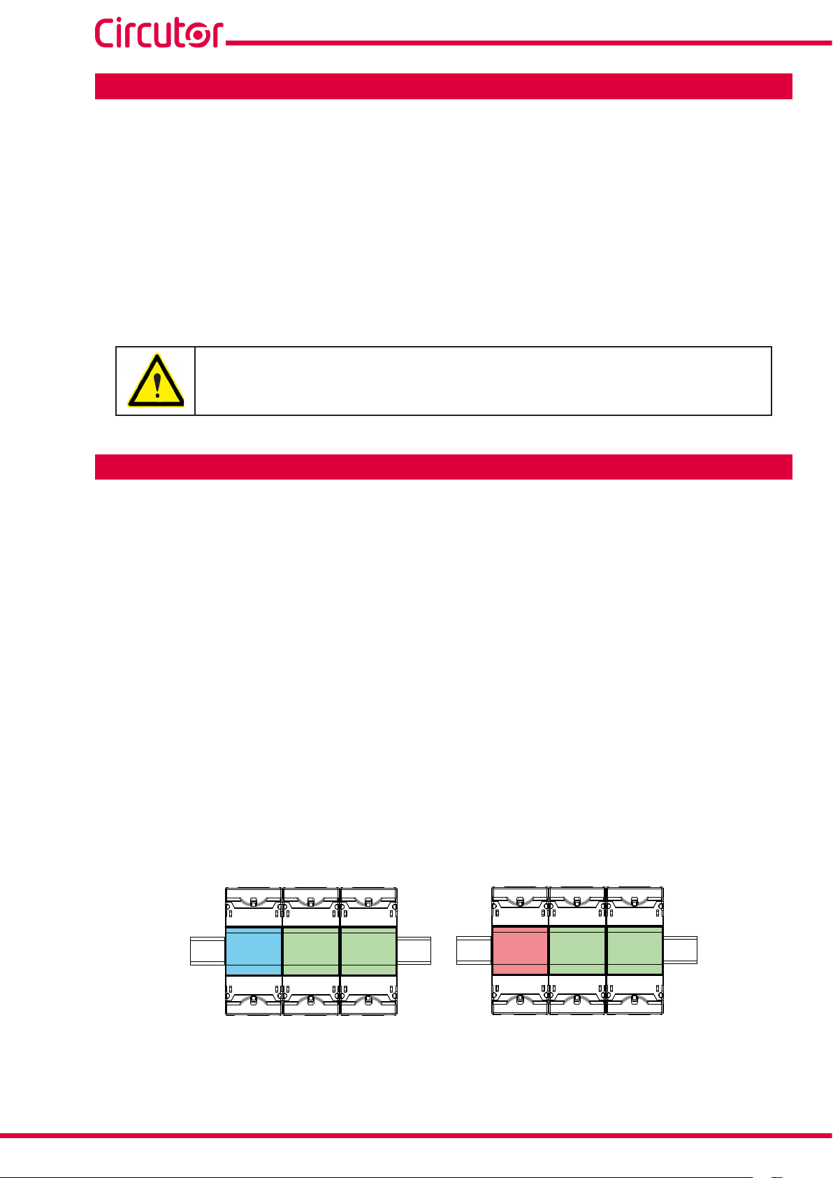
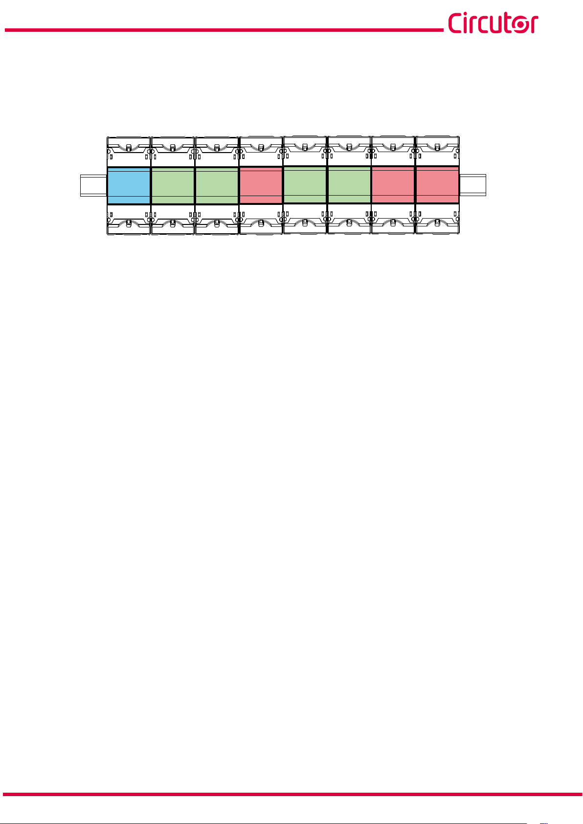
Each line-CVM or line-EDS device enables up to 2 expansion modules to be directly connected to their
right-hand side.
(1)
line-EDS line-M line-M
line-CVM
line-M line-M
Figure 1: Line-EDS and line CVM expansion module connection.
(1)
Expansion module types: line-M-4IO-R, line-M-4IO-T, line-M-4IO-RV, line-M-4IO-A and line-TCPRS1.
8
Instruction Manual
Page 9
line-M
The line-M-3G module can only be connected on the left side of line-EDS devices. If the line-EDS has
a line-M-3G connected to it, only 1 expansion module can be connected on its right side.
In installations with line-EDS devices a total of up to seven devices may be connected to their righthand side.
line-EDS line-M line-M
Figure 2: Typical installation of a line-EDS with 7 devices.
line-CVM
line-M line-M
line-CVM line-CVM
Note: An installation may only be fitted with one line-EDS device.
Note: In installations without line-EDS devices only one line-CVM may be installed.
Note: All line-EDS or line-CVM must be connected to the auxiliary power supply.
Instruction Manual
9
Page 10
line-M
3. INSTALLATION OF THE DEVICE
3.1.- PRELIMINARY RECOMMENDATIONS
In order to use the device safely, personnel operating it must follow the safety measures that comply with the standards of the country where it is to be installed; operators
must wear the required personal protective equipment (rubber gloves, approved facial
protection and flame-resistant clothing) to prevent injuries from electric shock or arcs
caused by exposure to current-carrying conductors, and they must heed the various
warnings indicated in this instruction manual.
The line-M device must be installed by authorised, qualified personnel.
The power supply plug must be disconnected and measurement systems switched off before handling,
altering the connections or replacing the device. It is dangerous to handle the device while it is powered.
Cables must always be kept in perfect condition to avoid accidents or injury to personnel or installations.
Restrict the operation of the device to the specified measurement category, voltage or current values.
The manufacturer of the device is not responsible for any damage resulting from failure by the user
or installer to heed the warnings and/or recommendations set out in this manual, nor for damage
resulting from the use of non-original products or accessories or those made by other manufacturers.
Do not use the device to take any measurements if an anomaly or malfunction is detected.
Check the surrounding environment before starting to take measurements. Do not take any measurements in hazardous or explosive environments.
Before carrying out maintenance, repair or handling of any of the device's connections,
the device must be disconnected from all power sources, both from the device's own
power supply and the measurement's.
Contact the after-sales service if you detect that the device is not working properly.
10
Instruction Manual
Page 11
line-M
3.2.- INSTALLATION
When the device is on, its terminals, opening covers or removing elements may expose the user to parts that are hazardous to touch. Do not use the device until it is
fully installed.
The device must be installed inside electric panel or enclosure, with DIN rail mounting (IEC 60715).
Before installing the expansion module, the line-CVM or line-EDS devices must be
disconnected from all power supplies, both the device's power supply itself and the
measurement's.
The line-M-3G module can only be connected on the left side of the line-EDS device.
The line-CVM and line-EDS devices may only have 2 expansion modules connected
to their right-hand side.
If the line-EDS has a line-M-3G connected to it, only 1 expansion module can be
connected on its right side.
See "2. PRODUCT DESCRIPTION".
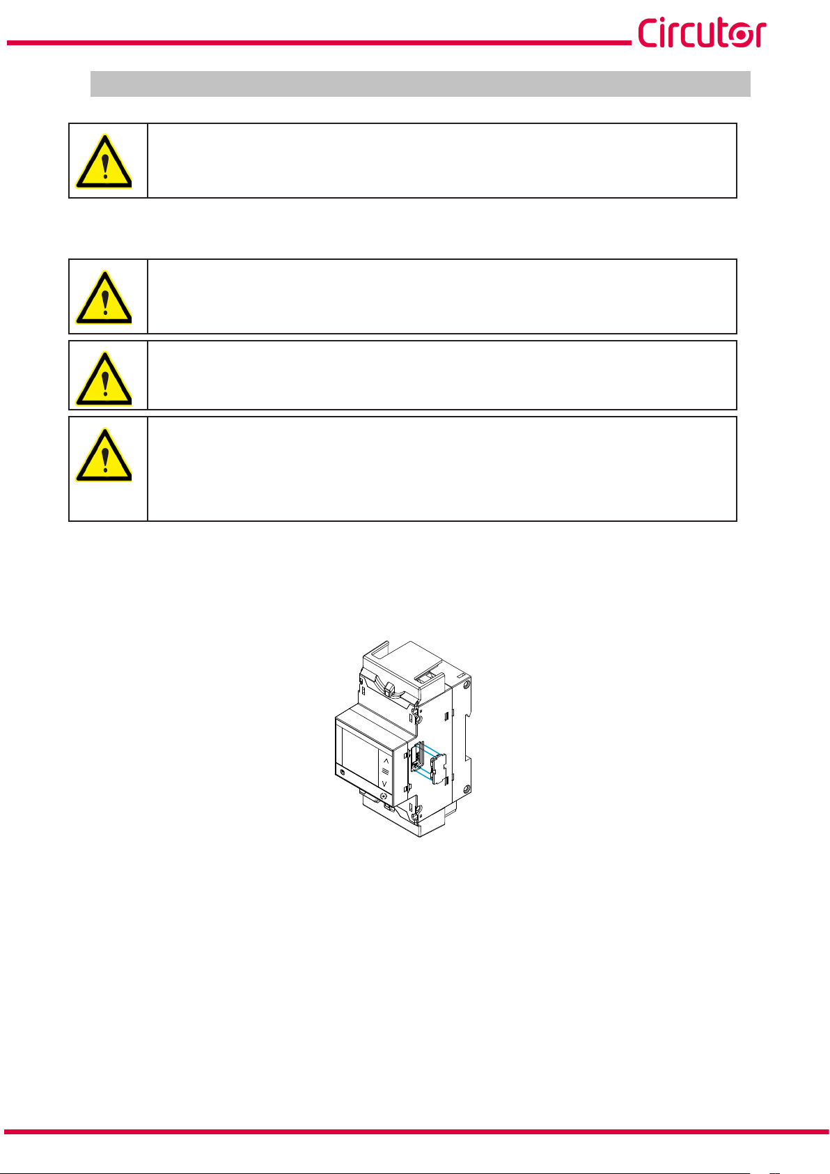
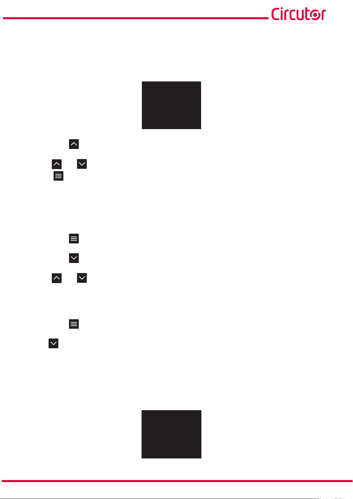
The steps to follow to connect the expansion modules are:
1.- Using a flat head screwdriver, remove the expansion connector's protective covers located on the
side of the devices, (Figure 3).
line-CVM-D32
Figure 3: Installation step 1.
2.- Insert the expansion connector and fastening clips into one of the devices (Figure 4).
Instruction Manual
11
Page 12
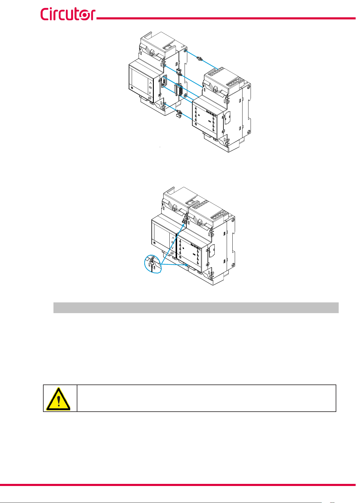
line-CVM-D32
Figure 4: Installation step 2.
3 .- Connect both devices and fasten them by pushing the front clips down (Figure 5).
line-M
line-CVM-D32
Figure 5: Installation step 3.
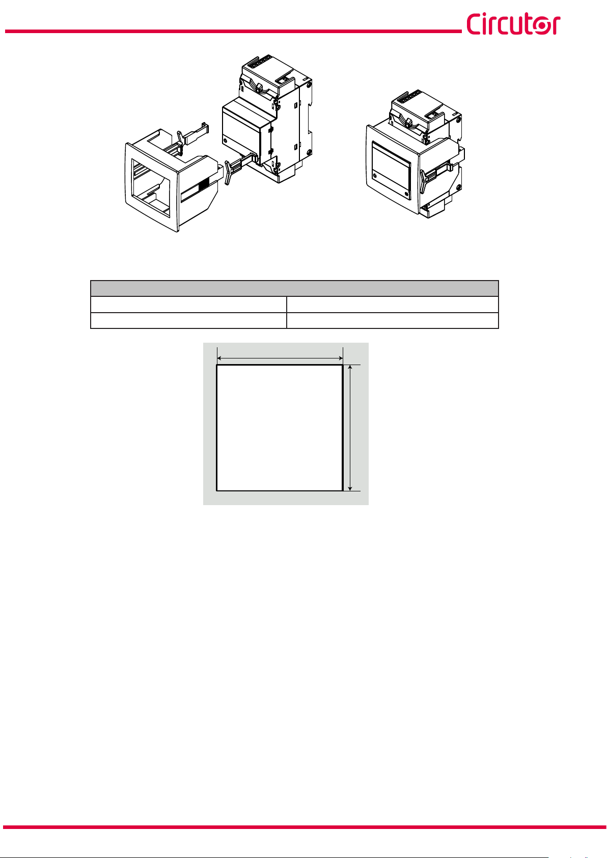
3.3.- PANEL ADAPTER 72 x 72 mm
Note: The panel adapter 72 x 72 mm is a separately sold accessory.
CIRCUTOR has a panel adapter for the line-M expansion modules for their installation on 72 x 72 mm
panels.
The Figure 6 illustrates how the panel adapter connects to a line-M.
Before installing the adapter, the device must be disconnected from all power and
measurement supplies.
12
Instruction Manual
Page 13
line-M
Figure 6: Installation of the panel adapter.
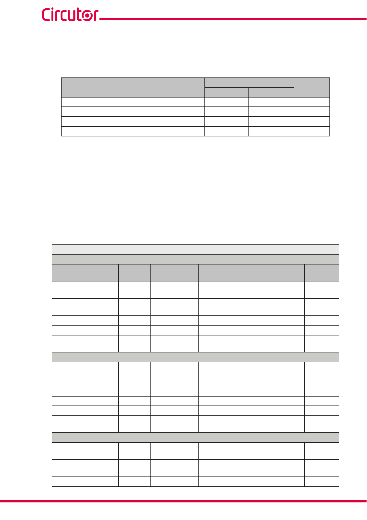
Table 3: Technical characteristics of the Panel Adapter.
Technical Specifications
Protection degree IP40
Enclosure Self-extinguishing V0 plastic
68 mm
Figure 7: Cut in the panel.
68 mm
Instruction Manual
13
Page 14
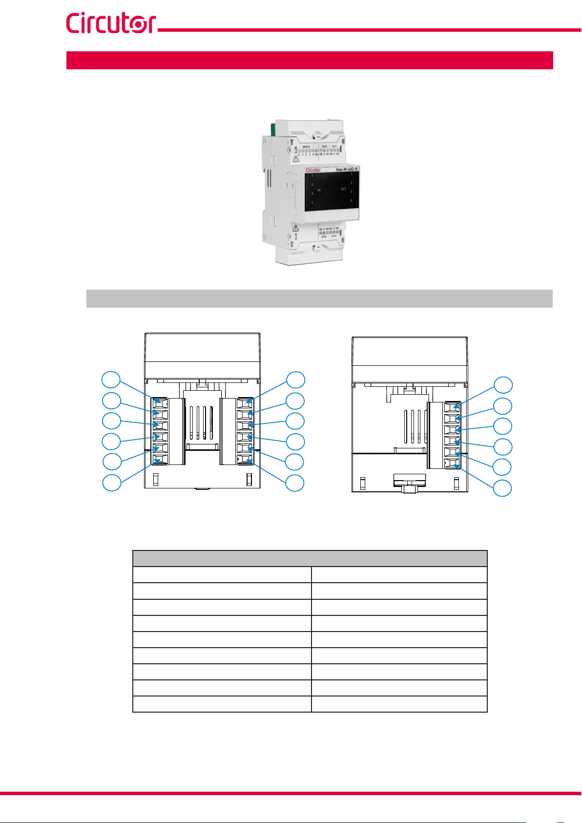
4. line-M-4IO-R
The line-M-4IO-R expansion module has 4 digital inputs and 4 relay outputs.
4.1.- DEVICE TERMINALS
line-M
12
11
10
1
2
3
9
8
7
Figure 8: Line-M-4IO-R terminals: Upper - Lower.
Table 4: List of line-M-4IO-R terminals.
4
5
6
Device terminals
1: C, Common digital inputs 10: NO, Relay Output 1 (NO)
2: 1, Digital input 1 11: C, Relay output 1 (Common)
3: 2, Digital input 2 12: NC, Relay output 1 (NC)
4: 3, Digital input 3 19: NO, Relay output 4 (NO)
5: 4, Digital input 4 20: C, Relay output 4 (Common)
6: Vcc, + 12V 21: NC, Relay output 4 (NC)
7: NO, Relay output 2 (NO) 22: NO, Relay output 3 (NO)
8: C, Relay output 2 (Common) 23: C, Relay output 3 (Common)
9: NC, Relay output 2 (NC) 24: NC, Relay output 3 (NC)
24
23
22
21
20
19
14
Instruction Manual
Page 15
line-M
4.2. - CONNECTION DIAGRAM
Enabling digital inputs with the device’s
internal source (+12 V)
Entradas digitales
Digital inputs
1 2 3 4
1
C
3k
1
2
3
4
6 12
+12 V
Relé 2
Relay 2
line-M-4IO-R
1
IN
2
OUT
3
4
Relé 1
Relay 1
Enabling digital inputs with an external
Entradas digitales
Digital inputs
+
24 V
-
1
C
3k
source (+24 V)
1 2 3 4
1
2
3
4
6 12
+12 V
Relé 2
Relay 2
line-M-4IO-R
1
IN
2
OUT
3
4
Relé 1
Relay 1
19
Relé 4
Relay 4
Relé 3
Relay 3
24
Figure 9: Line-M-4IO-R connection diagram.
19
Relé 4
Relay 4
Relé 3
Relay 3
24
Instruction Manual
15
Page 16
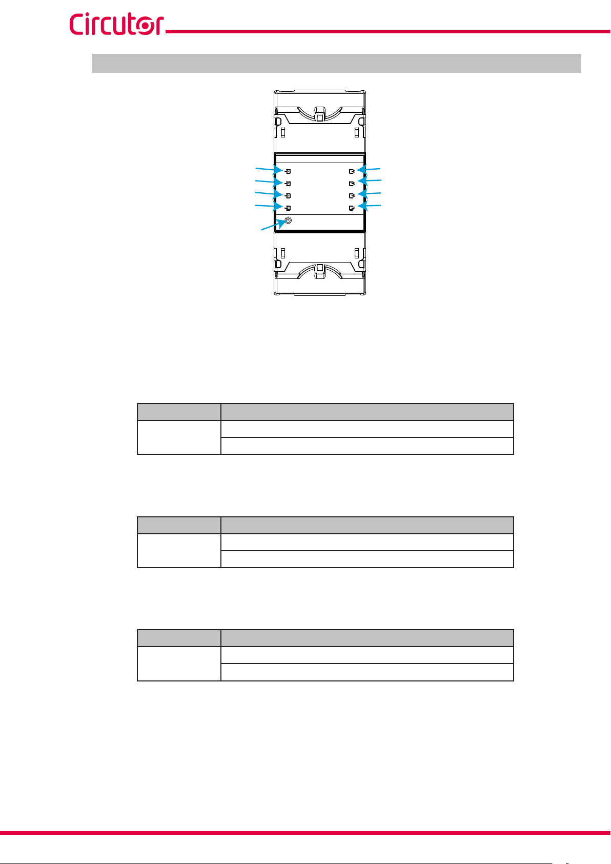
4.3 .- LED INDICATORS
line-M
IN 1
IN 2
IN 3
IN 4
CPU
Figure 10: LEDs: line-M-4IO-R.
The line-M-4IO-R have 9 indicating LEDs:
CPU, Indicates device status:
LED Description
CPU
Flashing:
White: Indicates that the device is powered
1
2
IN
3
4
Table 5: CPU LED.
line-M-4IO-R
OUT
1
2
3
4
OUT 1
OUT 2
OUT 3
OUT 4
IN x, Indicates digital input x status:
LED Description
IN x
On:
Green: Indicates activated input
OUT x, Indicates relay output x status:
LED Description
OUT x
On:
Red: Indicates activated output
Table 6: Led IN x.
Table 7: LED OUT x.
16
Instruction Manual
Page 17
line-M
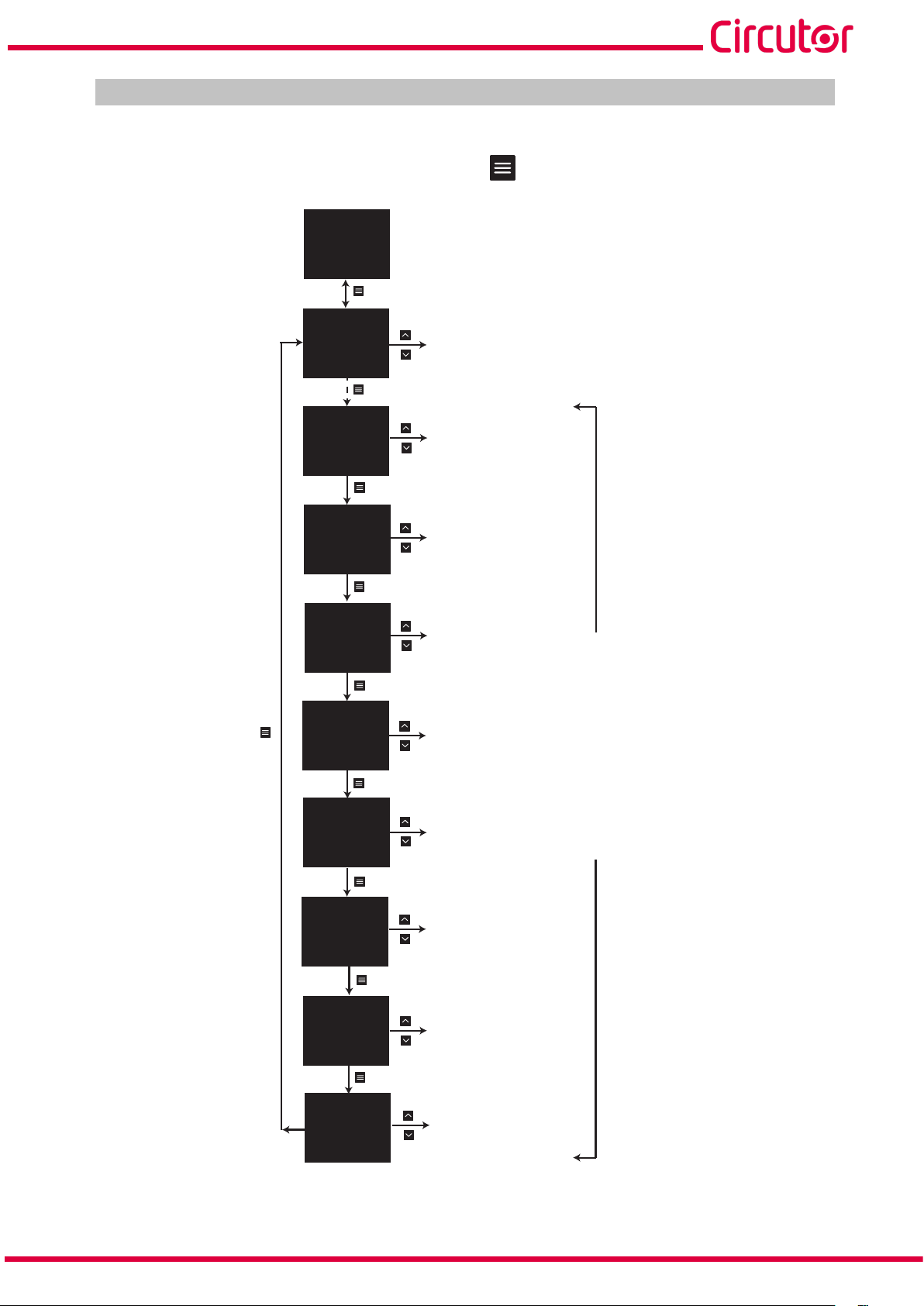
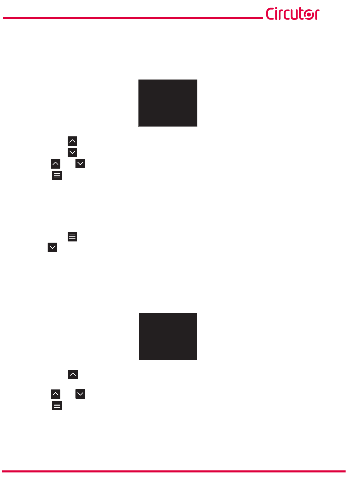
4.4.- CONFIGURATION line-M-4IO-R
Configuration via display of the line-M-4IO-R is carried out via line-CVM to which it is connected.
To access the configuration menu, hold down (>2s) key .
AVG
AVG
LIII
INST
SETUP
SETUP
PROG
SETUP
SETUP
230.00
5.00
50.00
1.00
PRIMARY VT
1.0
V
SECONDARY VT
1.00
MODE
IMPULSE
NAME
IN1
D IN1
MODE
IMPULSE
NAME
IN1
D IN2
MODE
IMPULSE
NAME
IN1
D IN3
V
A
Hz
cos
T1
MEASURE, Measurement parameters
V
MEASURE
D IN1, Digital Input 1
SLOT1
D IN2, Digital Input 2
SLOT1
CLOCK
PROG
D IN3, Digital Input 3
SLOT1
SETUP
SETUP
SETUP
SETUP
PROG
PROG
SETUP
PROG
MODE
IMPULSE
NAME
IN1
D IN4
VARIABLE
1 V1
D OUT1
VARIABLE
1 V1
D OUT2
VARIABLE
1 V1
D OUT3
VARIABLE
1 V1
D OUT4
SLOT1
SLOT1
kgCO2
OUT2
SLOT1
SLOT1
OUT1
SLOT1
OUT1
D IN4, Digital Input 4
D OUT1, Relay output 1
D OUT2, Relay output 2
VARIABLE
VARIABLE
PROG
D OUT3, Relay output 3
D OUT4, Relay output 4
Expansion module line-M-4IO-R
Instruction Manual
Figure 11: Configuration menu.
17
Page 18
line-M
Note: SLOT1 is the expansion module nearest line-CVM, SLOT2 is the following expansion module.
To exit the configuration menu, hold down (>2s) key .
4.4.1.- CONFIGURATION OF DIGITAL INPUTS 1 ... 4
Note: Digital input x configuration is identified by the literal D INx at the bottom centre of the display.
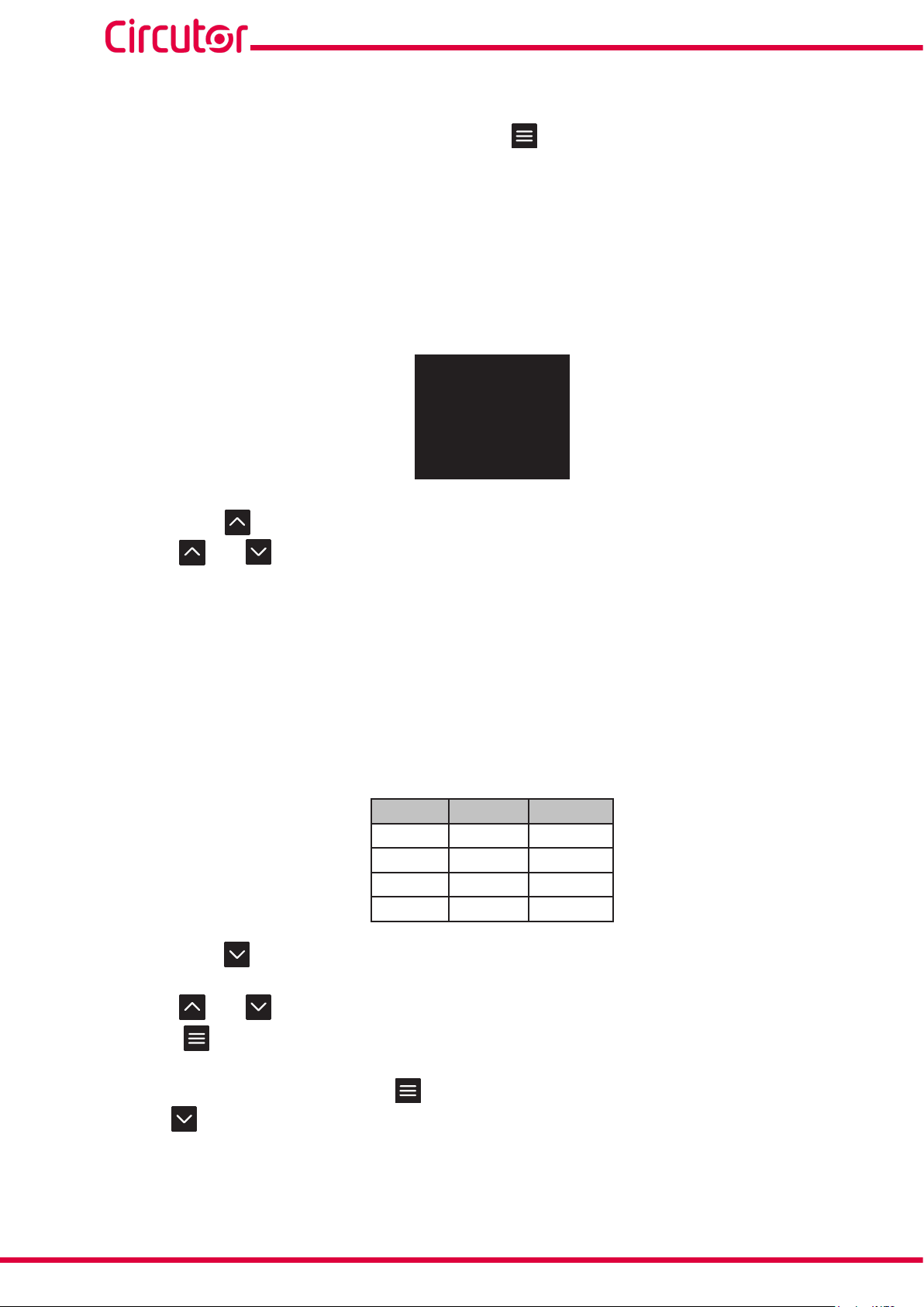
4.4.1.1.- Mode and name of digital input x
The operating mode and name of digital input x are configured on this screen.
MODE
IMPULSE
NAME
IN1
SETUP
D IN1
SLOT1
Hold down key to set operating mode (MODE).
Use keys and to skip through the different options:
IMPULSE, The digital input functions as a pulse input.
STATUS, Functions as a status input
TARIFF, It enables selection of tariff.
Note: The option TARIFF is only available for Digital inputs 1 and 2.
Note: To select the TARIFF, digital inputs 1 and 2 are needed simultaneously.
Note: If 2 modules are configured in the TARIFF option, the device will apply the tariff set in the second
module.
Table 8: Tariff selection.
D IN2 D IN1
Tariff 1 0 0
Tariff 2 0 1
Tariff 3 1 0
Tariff 4 1 1
Hold down key to set input name (NAME).
18
Use keys and to modify the digit's value.
Press key to skip through the digits.
To validate the option, hold down key .
Use key to skip to the next programming point.
Instruction Manual
Page 19
line-M
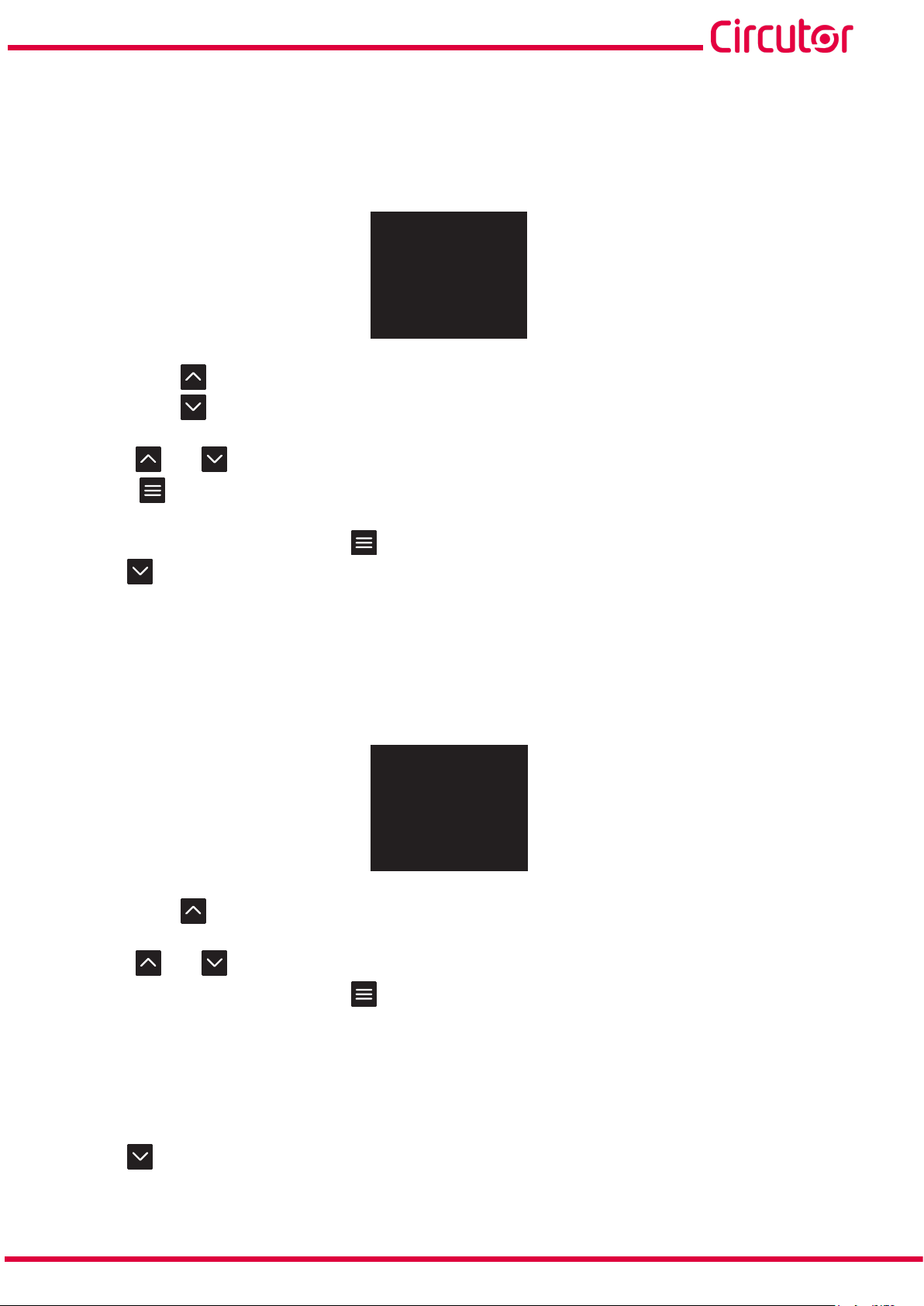
4.4.1.2.- Units and energy per pulse
Note: Screen visible if the selected operating mode is a pulse input, IMPULSE.
This screen enables unit and energy per pulse configuration.
UNITS
kWh
WEIGHT
1
SETUP
D IN1
SLOT1
Hold down key to set the units (UNITS).
Hold down key to set the energy per pulse (WEIGHT).
Use keys and to modify the digit's value.
Press key to skip through the digits.
To validate the option, hold down key .
Use key to skip to the next programming point.
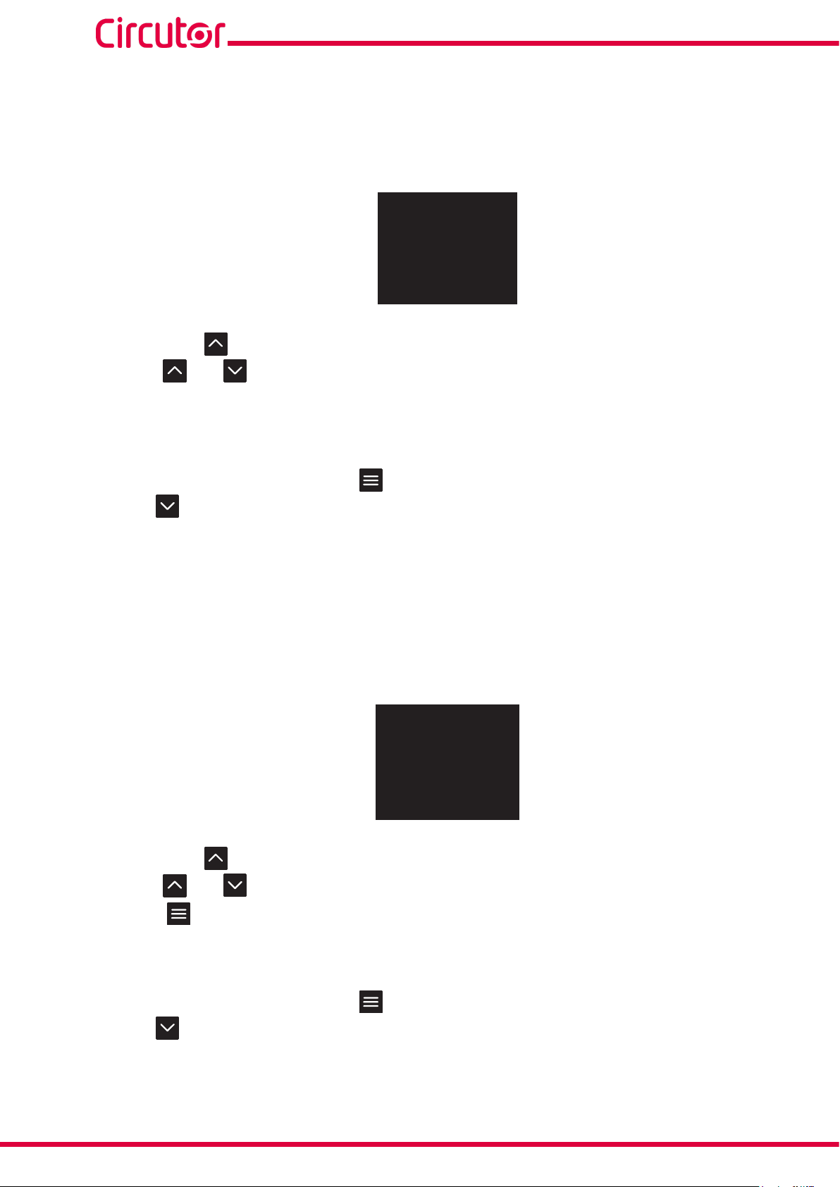
4.4.1.3.- Decimals
Note: Screen visible if the selected operating mode is a pulse input, IMPULSE.
This screen enables decimal number configuration.
DECIMALS
0
SETUP
D IN1
SLOT1
Hold down key to set number of decimals (DECIMALS).
Use keys and to modify the digit's value.
To validate the option, hold down key .
No. of decimals:
Minimum value: 0.
Maximum value: 9.
Use key to skip to the next programming point.
Instruction Manual
19
Page 20
4.4.1.4.- Input signal logic
Note: Screen visible if the selected operating mode is a pulse input, STATUS.
This screen enables configuration of input signal operating logic.
INPUT LOGIC
POSITIVE
line-M
SETUP
D IN1
SLOT1
Hold down key to set the operating logic (INPUT LOGIC).
Use keys and to skip through the different options:
POSITIVE, Positive logic, a high signal input shows 1 and a low signal input shows 0.
NEGATIVE, Negative logic, a high signal input shows 0 and a low signal input shows 1.
To validate the option, hold down key .
Use key to skip to the next programming point.
4.4.2.- CONFIGURATION OF RELAY OUTPUTS 1 ... 4
Note: Configuration of relay output x is shown by the literal D OUTx at the bottom centre of the display.
4.4.2.1.- Variable
This screen enables configuration of the relay output variable (VARIABLE).
VARIABLE
1 V1
SETUP
D OUT1
SLOT1
Hold down key to enter programming mode.
Use keys and to modify the digit's value.
Press key to skip through the digits.
The codes for the variables are shown in Table 9, Table 10, Table 11 and Table 12.
To validate the option, hold down key .
Use key to skip to the next programming point.
20
Instruction Manual
Page 21
line-M
Table 9: Variable codes for Output programming (Table 1).
Parameter Phase Code Phase Code Phase Code Phase Code
Phase-Neutral voltage L1 1 L2 9 L3 17 III 31
Phase-Phase voltage L12 28 L23 29 L31 30 III 32
Current L1 2 L2 10 L3 18 III 33
Frequency - 27 - - - - - Total Active Power L1 3 L2 11 L3 19 III 34
Consumed Active Power L1 700 L2 707 L3 714 III 721
Generated Active Power L1 728 L2 735 L3 742 III 749
Total Apparent Power L1 6 L2 14 L3 22 III 37
Consumed Apparent Power L1 704 L2 711 L3 718 III 725
Generated Apparent Power L1 732 L2 739 L3 746 III 753
Total Reactive Power L1 69 L2 70 L3 71 III 72
Total Consumed Reactive Power L1 703 L2 710 L3 717 III 724
Total Generated Reactive Power L1 731 L2 738 L3 745 III 752
Total Inductive Reactive Power L1 4 L2 12 L3 20 III 35
Consumed Inductive Reactive Power L1 701 L2 708 L3 715 III 722
Generated Inductive Reactive Power
L1 729 L2 736 L3 743 III 750
Total Capacitive Reactive Power L1 5 L2 13 L3 21 III 36
Consumed Capacitive Reactive
Power
L1 702 L2 709 L3 716 III 723
Generated Capacitive Reactive Power L1 730 L2 737 L3 744 III 751
Total Power Factor L1 7 L2 15 L3 23 III 38
Generated Power Factor L1 705 L2 712 L3 719 III 726
Consumed Power Factor L1 733 L2 740 L3 747 III 754
Cos φ Total L1 8 L2 16 L3 24 III 39
Cos φ Generated L1 706 L2 713 L3 720 III 727
Cos φ Consumed L1 734 L2 741 L3 748 III 755
THD% Voltage
THD % Current
Quality Parameter
(2)
The output is activated when any of the quality parameters (overvoltage, gap or interruption) meet the programmed
parameters.
(3)
These variables are not present when programming the Analogue Output variables.
(3)
(3)
(2) (3)
L1 40 L2 41 L3 42 - -
L1 44 L2 45 L3 46 - -
L1 109 L2 110 L3 111 III 112
The outputs are also configurable depending on the digital or analogue inputs of the connected expansion modules (Table 10).
Note: SLOT1 is the expansion module nearest line-CVM, SLOT2 is the following expansion module.
The code MANUAL
output”.
Instruction Manual
(4)
is used to manually activate the output, see “4.4.2.8.- Manual operation of the relay
21
Page 22
Table 10: Variable codes for Output programming (Table 2).
Parameter IN Code IN Code IN Code IN Code
Digital input SLOT1 1 902 2 903 3 904 4 905
Digital input SLOT2 1 910 2 911 3 912 4 913
Analogue input SLOT1 1 934 2 935 3 936 4 937
Analogue input SLOT1 1 942 2 943 3 944 4 945
MANUAL
(4)
Table 11: Variable codes for Output programming (Table 3).
0
Parameter Tariff Code Tariff Code Tariff Code
line-M
Maximum Current Demand L1
Maximum L2 Current Demand L2
(3)
(3)
Maximum Current Demand L3
Maximum Current Demand III
Maximum Active Power Demand L1
Maximum Active Power Demand L2
Maximum Active Power Demand L3
Maximum Active Power Demand III
(3)
(3)
(3)
(3)
(3)
Maximum Apparent Power Demand L1
Maximum Apparent Power Demand L2
Maximum Apparent Power Demand L3
Maximum Apparent Power Demand III
Consumption hour no.
Generation hour no.
Consumption cost
Generation cost
(3)
(3)
(3)
(3)
T1 600 T2 612 T3 624
T4 636 - - - T1 601 T2 613 T3 625
T4 637 - - - T1 602 T2 614 T3 626
T4 638 - - - T1 603 T2 615 T3 627
T4 639 - - - T1 604 T2 616 T3 628
T4 640 - - - T1 605 T2 617 T3 629
T4 641 - - - T1 606 T2 618 T3 630
T4 642 - - - T1 607 T2 619 T3 631
T4 643 - - - T1 608 T2 620 T3 632
T4 644 - - - T1 609 T2 621 T3 633
T4 645 - - - T1 610 T2 622 T3 634
T4 646 - - - T1 611 T2 623 T3 635
T4 647 - - - T1 531 T2 537 T3 543
T4 549 Total 585 - T1 534 T2 540 T3 546
T4 552 Total 588 - T1 529 T2 535 T3 541
T4 547 Total 583 - T1 532 T2 538 T3 544
T4 550 Total 586 - -
22
CO2 emissions from consumption
T1 530 T2 536 T3 542
T4 548 Total 584 - -
Instruction Manual
Page 23
line-M
Table 11 (Continuation): Variable codes for Output programming (Table 3).
Parameter Tariff Code Tariff Code Tariff Code
CO2 emissions from generation
Table 12: Variable codes for Output programming (Energy Pulses).
T1 533 T2 539 T3 545
T4 551 Total 587 - -
Parameter
Consumed Active Energy
Generated Active Energy
Consumed Reactive
Energy
Generated Reactive
Energy
Consumed Inductive
Reactive Energy
Generated Inductive
Reactive Energy
Consumed Capacitive
Reactive Energy
L1 L2 L3 III
Tariff Code Tariff Code Tariff Code Tariff Code
T1 129 T1 134 T1 139 T1 144
T2 169 T2 174 T2 179 T2 184
T3 209 T3 214 T3 219 T3 224
T4 249 T4 254 T4 259 T4 264
Total 489 Total 494 Total 499 Total 504
T1 149 T1 154 T1 159 T1 164
T2 189 T2 194 T2 199 T2 204
T3 229 T3 234 T3 239 T3 244
T4 269 T4 274 T4 279 T4 284
Total 509 Total 514 Total 519 Total 524
T1 132 T1 137 T1 142 T1 147
T2 172 T2 177 T2 182 T2 187
T3 212 T3 217 T3 222 T3 227
T4 252 T4 257 T4 262 T4 267
Total 492 Total 497 Total 502 Total 507
T1 152 T1 157 T1 162 T1 167
T2 192 T2 197 T2 202 T2 207
T3 232 T3 237 T3 242 T3 247
T4 272 T4 277 T4 282 T4 287
Total 512 Total 517 Total 522 Total 527
T1 130 T1 135 T1 140 T1 145
T2 170 T2 175 T2 180 T2 185
T3 210 T3 215 T3 220 T3 225
T4 250 T4 255 T4 260 T4 265
Total 490 Total 495 Total 500 Total 505
T1 150 T1 155 T1 160 T1 165
T2 190 T2 195 T2 200 T2 205
T3 230 T3 235 T3 240 T3 245
T4 270 T4 275 T4 280 T4 285
Total 510 Total 515 Total 520 Total 525
T1 131 T1 136 T1 141 T1 146
T2 171 T2 176 T2 181 T2 186
T3 211 T3 216 T3 221 T3 226
T4 251 T4 256 T4 261 T4 266
Total 491 Total 496 Total 501 Total 506
Instruction Manual
23
Page 24
Table 12 (Continuation): Variable codes for Output programming (Energy Pulses).
Parameter
Generated Capacitive
Reactive Energy
Consumed Apparent Energy
Generated Apparent
Energy
line-M
L1 L2 L3 III
Tariff Code Tariff Code Tariff Code Tariff Code
T1 151 T1 156 T1 161 T1 166
T2 191 T2 196 T2 201 T2 206
T3 231 T3 236 T3 241 T3 246
T4 271 T4 276 T4 281 T4 286
Total 511 Total 516 Total 521 Total 526
T1 133 T1 138 T1 143 T1 148
T2 173 T2 178 T2 183 T2 188
T3 213 T3 218 T3 223 T3 228
T4 253 T4 258 T4 263 T4 268
Total 493 Total 498 Total 503 Total 508
T1 153 T1 158 T1 163 T1 168
T2 193 T2 198 T2 203 T2 208
T3 233 T3 238 T3 243 T3 248
T4 273 T4 278 T4 283 T4 288
Total 513 Total 518 Total 523 Total 528
4.4.2.2.- Maximum and minimum values
Note: Screen visible if the selected digital output variable is in Table 9, Table 10 or Table 11.
This screen enables maximum and minimum alarm variable configuration.
HIGH VALUE
0.0 V
LOW VALUE
0.0 V
SETUP
D OUT1
SLOT1
Hold down key to set maximum value (HIGH VALUE), i.e. the value above which the alarm is activated.
Hold down key to set minimum value (LOW VALUE), i.e. the value below which the alarm is activated.
Use keys and to modify the digit's value.
Press key to skip through the digits.
24
Note: maximum and minimum programming value depends on the selected variable.
Hold down key to validate the value.
Use key to skip to the next programming point.
Instruction Manual
Page 25
line-M
4.4.2.3.- Connection and disconnection delay
Note: Screen visible if the selected digital output variable is in Table 9, Table 10 or Table 11.
This screen enables alarm connection and disconnection delay configuration in seconds.
DELAY ON
0 S
DELAY OFF
0 S
SETUP
D OUT1
SLOT1
Hold down key to set connection delay (DELAY ON).
Hold down key to set disconnection delay (DELAY OFF).
Use keys and to modify the digit's value.
Press key to skip through the digits.
Connection and Disconnection delay:
Minimum value: 0 s.
Maximum value: 65499 s.
Hold down key to validate the value.
Use key to skip to the next programming point.
4.4.2.4.- Hysteresis and status of contacts
Note: Screen visible if the selected digital output variable is in Table 9, Table 10 or Table 11.
This screen enables hysteresis value and contact status configuration.
HYSTERESIS
0%
CONTACT TYPE
NO
SETUP
D OUT1
SLOT1
Hold down key to set hysteresis value (HYSTERESIS), the difference between the alarm on and off
value in %.
Use keys and to modify the digit's value.
Press key to skip through the digits.
Hysteresis:
Minimum value: 0%.
Maximum value: 99%.
Instruction Manual
25
Page 26
Hold down key to set contact status (CONTACT TYPE).
Use keys and to skip through the different options:
NC, Contact normally closed.
NO, Contact normally open.
Hold down key to validate the value.
Use key to skip to the next programming point.
4.4.2.5.- Latch
Note: Screen visible if the selected digital output variable is in Table 9, Table 10 or Table 11.
This screen enables alarm latch configuration.
line-M
LATCH
NO
TIME ON
0
S
SETUP
D OUT1
SLOT1
Hold down key to set latch (LATCH), i.e. if it remains interlocked after the alarm is triggered, even if
the event that triggered it disappears.
Use keys and to skip through the different options:
NO, Latching is not activated.
YES, Latching is activated.
TIME, Alarm latching is activated for a set time, Latching time.
Hold down key to validate the value.
Hold down key to set Latching time (TIME ON). The time in seconds that the alarm is interlocked is
displayed. After such time, if the alarm status no longer applies, disconnection delay is activated.
26
Use keys and to modify the digit's value.
Press key to skip through the digits.
Latching time:
Minimum value: 0 s.
Maximum value: 65499 s.
Hold down key to validate the value.
Use key to skip to the next programming point.
Instruction Manual
Page 27
line-M
4.4.2.6.- Energy per pulse and contact status
Note: Screen visible if the selected digital output variable is an energy, see Table 12.
This screen enables energy per pulse and contact status configuration.
WEIGHT
1Wh
CONTACT TYPE
NO
SETUP
D OUT1
SLOT1
Hold down key to set the energy per pulse (WEIGHT).
Use keys and to modify the digit's value.
Press key to skip through the digits.
Energy per pulse:
Minimum value: 1 wh / varLh / varCh / varh / VAh.
Maximum value: 1999999 wh / varLh / varCh / varh / VAh.
Hold down key to validate the value.
Hold down key to set contact status (CONTACT TYPE).
Use keys and to skip through the different options:
NC, Contact normally closed.
NO, Contact normally open.
Hold down key to validate the value.
Use key to skip to the next programming point.
4.4.2.7.- Pulse
Note: Screen visible if the selected digital output variable is an energy, see Table 12.
This screen enables pulse width configuration
HIGH PERIOD
x10
0
ms
LOW PERIOD
x10
0
ms
Instruction Manual
SETUP
D OUT1
SLOT1
27
Page 28
Hold down key to set pulse width to a high level (HIGH PERIOD).
Hold down key to set pulse width to a low level (LOW PERIOD).
Use keys and to modify the digit's value.
Press key to skip through the digits.
Pulse width:
Minimum value: 0 x 10 ms.
Maximum value: 999 x 10 ms.
Hold down key to validate the value.
Use key to skip to the next programming point.
4.4.2.8.- Manual operation of the relay output
Note: Screen visible if the selected relay output variable is MANUAL, see Table 10.
line-M
This screen enables manual relay output activation.
STATUS
OFF
CONTACT TYPE
NO
SETUP
D OUT1
SLOT1
Hold down key to set output status (STATUS).
Use keys and to skip through the different options:
OFF, Disconnected output.
ON, Connected output.
Hold down key to set contact status (CONTACT TYPE).
Use keys and to skip through the different options:
28
NC, Contact normally closed.
NO, Contact normally open.
Hold down key to validate the value.
Use key to skip to the next programming point.
Instruction Manual
Page 29
line-M
4.5.- MODBUS MEMORY MAP line-M-4IO-R
Note: For all modbus map parameters, SLOT1 corresponds to the first expansion module connected to
the right-hand side of the line-CVM-D and SLOT2 corresponds to the second connected module.
4.5.1.- INPUT AND OUTPUT STATUS
The Function 0x02, is implemented for these variables.
Table 13: Modbus Memory Map: Output and input status.
Parameter Format
Digital input 1 bool C5A8 C990 0: Deactivated - 1: activated
Digital input 2 bool C5AC C994 0: Deactivated - 1: activated
Digital input 3 bool C5B0 C998 0: Deactivated - 1: activated
Digital input 4 bool C5B4 C99C 0: Deactivated - 1: activated
Relay output 1 bool C679 CA61 0: Deactivated - 1: activated
Relay output 2 bool C68D CA75 0: Deactivated - 1: activated
Relay output 3 bool C6A1 CA89 0: Deactivated - 1: activated
Relay output 4 bool C6B5 CA9D 0: Deactivated - 1: activated
Address
SLOT 1 SLOT 2
Value
4.5.2.- PULSE METERS
The Function 0x04: register readout, is implemented for these variables.
Table 14: Modbus Memory Map: Pulse meter.
Parameter Format
Pulse counter of digital input 1 Uint [64]
Pulse counter of digital input 2 Uint [64]
Pulse counter of digital input 3 Uint [64]
Pulse counter of digital input 4 Uint [64]
SLOT 1 SLOT 2
C5A8 - C5A9 -
C5AA - C5AB
C5AC - C5AD -
C5AE - C5AF
C5B0 - C5B1 -
C5B2 - C5B3
C5B4-C5B5-
C5B6-C5B7
Address
C990 - C991 -
C992 - C993
C994 - C995 -
C996 - C997
C998 - C999 -
C99A - C99B
C99C-C99D-
C99E-C99F
Parameter deletion is carried out by Function 05: writing a relay.
Table 15: Modbus Memory Map: Pulse meter deletion.
Deleting parameters Format
Deleting the pulse counter from digital input 1 Bool C710 CAF8 0xFF00
Address
SLOT 1 SLOT 2
Value to be sent
Deleting the pulse counter from digital input 2 Bool C711 CAF9 0xFF00
Deleting the pulse counter from digital input 3 Bool C712 CAFA 0xFF00
Deleting the pulse counter from digital input 4 Bool C713 CAFB 0xFF00
Instruction Manual
29
Page 30
4.5.3.- ALARMS
The Function 0x04, is implemented for these variables.
Table 16: Modbus Memory Map: Alarms.
Parameter Format
Output relay 1 alarm activation date Uint [32] C677-C678 CA5F-CA60 Epoch
Output relay 2 alarm activation date Uint [32] C68B-C68C CA73-CA74 Epoch
Output relay 3 alarm activation date Uint [32] C69F-6CA0 CA87-CA88 Epoch
Output relay 4 alarm activation date Uint [32] C6B3-C6B4 CA9B-CA9C Epoch
(5)
Date and time are given in Epoch format.
4.5.4.- DEVICE CONFIGURATION VARIABLES
The following functions are used for these variables:
Address
SLOT 1 SLOT 2
Units
line-M
(5)
Function 0x03: register readout.
Function 0x10: Writing multiple registers.
4.5.4.1.- Digital Input Configuration
Table 17: Modbus Memory Map: Digital Inputs.
SLOT 1
Digital Input 1
Parameter Format Address Valid data range
(6) (7)
Mode
Name String
(9)
Units
Decimals
Input signal logic
(9)
(10)
Int [16] C4E0
C4E3-C4E4-
C4E5-C4E6
String C4E7-C4E8-C4E9 - -
Uint [16] C4E2 0... 9 0
Uint [16] C4E1
Digital input 2
(6) (7)
Mode
Name String
(9)
Units
Decimals
Input signal logic
(9)
(10)
Int [16] C4EC
C4EF-C4F0-
C4F1-C4F2
String C4F3-C4F4-C4F5 - -
Uint [16] C4EE 0... 9 0
Uint [16] C4ED
Digital input 3
Mode Int [16] C4F8
Name String
(9)
Units
String C4FF-C500-C501 - -
C4FB-C4FC-
C4FD-C4FE
- 1: Tariff - 0: Status input -
> 0: Pulse input (energy per pulse)
0: Positive logic
1: Negative logic
- 1: Tariff - 0: Status input -
> 0: Pulse input (energy per pulse)
0: Positive logic
1: Negative logic
0: Status input -
> 0: Pulse input (energy per pulse)
Default
value
(8)
-
0
-
0
(8)
-
0
-
0
(8)
-
0
-
30
Instruction Manual
Page 31

line-M
Table 17 (Continuation): Modbus Memory Map: Digital Inputs.
Parameter Format Address Valid data range
(9)
(6) (7)
(9)
(6) (7)
(9)
(9)
(9)
(10)
Uint [16] C4FA 0... 9 0
Uint [16] C4F9
0: Positive logic
1: Negative logic
0: Status input -
> 0: Pulse input (energy per pulse)
C507-C508-
C509-C50A
String
(9)
(10)
Uint [16] C506 0... 9 0
Uint [16] C505
C50B-C50C-
C50D
0: Positive logic
1: Negative logic
SLOT 2
Int [16] C8C8
- 1: Tariff - 0: Status input -
> 0: Pulse input (energy per pulse)
C8CB-C8CC-
C8CD-C8CE
String
(9)
(10)
Uint [16] C8CA 0... 9 0
Uint [16] C8C9
Int [16] C8D4
C8CF-C8D0-
C8D1
0: Positive logic
1: Negative logic
- 1: Tariff - 0: Status input -
> 0: Pulse input (energy per pulse)
C8D7-C8D8-
C8D9-C8DA
String
(9)
(10)
Uint [16] C8D6 0... 9 0
Uint [16] C8D5
C8DB-C8DC-
C8DD
0: Positive logic
1: Negative logic
0: Status input -
> 0: Pulse input (energy per pulse)
C8E3-C8E4-
C8E5-C8E6
String
(9)
(10)
Uint [16] C8E2 0... 9 0
Uint [16] C8E1
C8E7-C8E8-
C8E9
0: Positive logic
1: Negative logic
0: Status input -
> 0: Pulse input (energy per pulse)
C8EF-C8F0-
C8F1-C8F2
Decimals
Input signal logic
Digital input 4
Mode Int [16] C504
Name String
Units
Decimals
Input signal logic
Digital Input 1
Mode
Name String
Units
Decimals
Input signal logic
Digital input 2
Mode
Name String
Units
Decimals
Input signal logic
Digital input 3
Mode Int [16] C8E0
Name String
Units
Decimals
Input signal logic
Digital input 4
Mode Int [16] C8EC
Name String
Default
value
(8)
-
-
(8)
-
-
(8)
-
-
(8)
-
- -
(8)
-
0
0
-
-
0
0
-
-
0
0
-
-
0
0
-
0
0
-
Instruction Manual
31
Page 32

line-M
Table 17 (Continuation): Modbus Memory Map: Digital Inputs.
Parameter Format Address Valid data range
(9)
Units
Decimals
Input signal logic
(6)
If 2 modules are configured in the TARIFF option, the device will apply the tariff set in the second module.
(7)
To select the Tariff mode, Digital Inputs 1 and 2 must be configured as tariffs simultaneously. See Table 8 to select the
(9)
(10)
String
Uint [16] C8EE 0... 9 0
Uint [16] C8ED
C8F3-C8F4-
C8F5
0: Positive logic
1: Negative logic
-
Default
value
-
0
tariff.
(8)
To configure the Operating Mode as pulse input, this parameter must be set to Energy per pulse (Value > 0).
(9)
Parameters to be configured if pulse input mode has been selected.
(10)
Parameters to be configured if if status input mode has been selected.
4.5.4.2.- Relay Output Configuration
Table 18: Modbus Memory Map: Relay outputs.
SLOT 1
Relay output 1
Configuration parameters Format Address Valid data range Default value
Variable Uint [16] C350
(13)
(13)
(14)
/
Float [32] C352-C353 Depends on the selected variable
Float [32] C354-C355 Depends on the selected variable -
(14)
(14)
Uint [16] C356
Uint [16] C357
Maximum value
Energy per pulse
Minimum value
Connection delay
High level pulse width
Disconnection delay
Low level pulse width
Hysteresis Uint [16] C358 0... 99% 0%
Contact status Uint [16] C351
Latch Bool C359 0: No - 1: Yes
Latching time Uint [16] C35A 0... 65499 s 0 s
Output unlocking
Manual Operation:
Output status
(11) (12)
(11)
Bool C670
Bool C679
Relay output 2
Variable Uint [16] C364
(13)
(13)
(14)
/
Float [32] C366 - C367 Depends on the selected variable
Float [32] C368 - C369 Depends on the selected variable -
(14)
(14)
Uint [16] C36A
Uint [16] C36B
Maximum value
Energy per pulse
Minimum value
Connection delay
High level pulse width
Disconnection delay
Low level pulse width
Hysteresis Uint [16] C36C 0... 99% 0%
Contact status Uint [16] C365
0: Manual - Table 9 - Table 10 -
Table 11 - Table 12
0... 65499 s 0 s
0... 999 ms (x10)
0... 65499 s 0 s
0... 999 ms (x10)
0: Normally open -
1: Normally closed
0
ON (Connect output): FF00
OFF (Disconnect output): 0000
0: Manual - Table 9 - Table 10 -
Table 11 - Table 12
0... 65499 s 0 s
0... 999 ms (x10)
0... 65499 s 0 s
0... 999 ms (x10)
0: Normally open -
1: Normally closed
0
-
0
0
0
0
-
0
32
Instruction Manual
Page 33

line-M
Table 18 (Continuation): Modbus Memory Map: Relay outputs.
Configuration parameters Format Address Valid data range Default value
Latch Bool C36D 0: No - 1: Yes
Latching time Uint [16] C36E 0... 65499 s 0 s
Output unlocking
Manual Operation:
Output status
(11) (12)
(12)
Bool C684
Bool C68D
ON (Connect output): FF00
OFF (Disconnect output): 0000
Relay output 3
Variable Uint [16] C378
Maximum value
Energy per pulse
Minimum value
Connection delay
High level pulse width
Disconnection delay
Low level pulse width
(13)
(13)
(14)
/
Float [32] C37A-C37B Depends on the selected variable
Float [32] C37C-C37D Depends on the selected variable -
(14)
(14)
Uint [16] C37E
Uint [16] C37F
0: Manual - Table 9 - Table 10 -
Table 11 - Table 12
0... 999 ms (x10)
0... 999 ms (x10)
Hysteresis Uint [16] C380 0... 99% 0%
Contact status Uint [16] C379
0: Normally open -
1: Normally closed
Latch Bool C381 0: No - 1: Yes
Latching time Uint [16] C382 0... 65499 s 0 s
Output unlocking
Manual Operation:
Output status
(11) (12)
(11)
Bool C698
Bool C6A1
ON (Connect output): FF00
OFF (Disconnect output): 0000
Relay output 4
Variable Uint [16] C38C
Maximum value
Energy per pulse
Minimum value
Connection delay
High level pulse width
Disconnection delay
Low level pulse width
(13)
(13)
(14)
/
Float [32] C38E - C38F Depends on the selected variable
Float [32] C390 - C391 Depends on the selected variable -
(14)
(14)
Uint [16] C392
Uint [16] C393
0: Manual - Table 9 - Table 10 -
Table 11 - Table 12
0... 999 ms (x10)
0... 999 ms (x10)
Hysteresis Uint [16] C394 0... 99% 0%
Contact status Uint [16] C38D
0: Normally open -
1: Normally closed
Latch Bool C395 0: No - 1: Yes
Latching time Uint [16] C396 0... 65499 s 0 s
Output unlocking
Manual Operation:
Output status
(11) (12)
(11)
Bool C6AC
Bool C6B5
ON (Connect output): FF00
OFF (Disconnect output): 0000
SLOT 2
Relay output 1
Variable Uint [16] C738
Maximum value
Energy per pulse
(13)
(14)
/
Float [32] C73A-C73B Depends on the selected variable
0: Manual - Table 9 - Table 10 -
Table 11 - Table 12
0
0... 65499 s 0 s
0... 65499 s 0 s
0
0... 65499 s 0 s
0... 65499 s 0 s
0
0
0
0
-
0
0
0
0
-
0
0
0
0
-
Instruction Manual
33
Page 34

Table 18 (Continuation): Modbus Memory Map: Relay outputs.
Configuration parameters Format Address Valid data range Default value
Minimum value
Connection delay
High level pulse width
Disconnection delay
Low level pulse width
(13)
(14)
(14)
Float [32] C73C-C73D Depends on the selected variable -
Uint [16] C73E
Uint [16] C73F
0... 65499 s 0 s
0... 999 ms (x10)
0... 65499 s 0 s
0... 999 ms (x10)
Hysteresis Uint [16] C740 0... 99% 0%
Contact status Uint [16] C739
0: Normally open -
1: Normally closed
0
Latch Bool C741 0: No - 1: Yes
Latching time Uint [16] C742 0... 65499 s 0 s
Output unlocking
Manual Operation:
Output status
(11) (12)
(11)
Bool CA58
Bool CA61
ON (Connect output): FF00
OFF (Disconnect output): 0000
0
0
0
Relay output 2
Variable Uint [16] C74C
(13)
(13)
(14)
/
Float [32] C74E-C74F Depends on the selected variable
Float [32] C750-C751
Maximum value
Energy per pulse
Minimum value
Connection delay
High level pulse width
(14)
Uint [16] C752
Disconnection delay
Low level pulse width
(14)
Uint [16] C753
0: Manual - Table 9 - Table 10 -
Table 11 - Table 12
Depends on the selected variable
0... 65499 s
0... 999 ms (x10)
0... 65499 s
0... 999 ms (x10)
0
-
-
0 s
0 s
Hysteresis Uint [16] C754 0... 99% 0%
Contact status Uint [16] C74D
Latch Bool C755
Latching time Uint [16] C756
Output unlocking
Manual Operation:
Output status
(11) (12)
(11)
Bool CA6C
Bool CA75
0: Normally open -
1: Normally closed
0: No - 1: Yes
0... 65499 s
0
ON (Connect output): FF00
OFF (Disconnect output): 0000
0
0 s
0
0
Relay output 3
Variable Uint [16] C760
(13)
(13)
(14)
/
Float [32] C762-C763 Depends on the selected variable
Float [32] C764-C765
Maximum value
Energy per pulse
Minimum value
Connection delay
High level pulse width
Disconnection delay
(14)
(14)
Uint [16] C766
Uint [16] C767
Low level pulse width
0: Manual - Table 9 - Table 10 -
Table 11 - Table 12
Depends on the selected variable
0... 65499 s
0... 999 ms (x10)
0... 65499 s
0... 999 ms (x10)
0
-
-
0 s
0 s
Hysteresis Uint [16] C768 0... 99% 0%
Contact status Uint [16] C761
Latch Bool C769
0: Normally open -
1: Normally closed
0: No - 1: Yes
0
line-M
34
Instruction Manual
Page 35

line-M
Table 18 (Continuation): Modbus Memory Map: Relay outputs.
Configuration parameters Format Address Valid data range Default value
Latching time Uint [16] C76A
Output unlocking
Manual Operation:
Output status
(11) (12)
(11)
Bool CA80
Bool CA89
ON (Connect output): FF00
OFF (Disconnect output): 0000
Relay output 4
Variable Uint [16] C774
(13)
(13)
(14)
/
Float [32] C776-C777 Depends on the selected variable
Float [32] C778-C779
Maximum value
Energy per pulse
Minimum value
0: Manual - Table 9 - Table 10 -
Depends on the selected variable
Connection delay
High level pulse width
(14)
Uint [16] C77A
Disconnection delay
Low level pulse width
(14)
Uint [16] C77B
Hysteresis Uint [16] C77C 0... 99% 0%
Contact status Uint [16] C775
Latch Bool C77D
Latching time Uint [16] C77E
Output unlocking
(11)
Manual Operation:
Output status
(11)
Functions 0x01 and 0x05 are used and for this variable.
(12)
Parameters to be configured if the parameter Variable has been selected as Manual.
(13)
Parameters to be configured if the parameter Variable has been selected from those in Table 9 - Table 10 - Table 11.
(14)
Parameters to be configured if the parameter Variable has been selected in Table 12.
(11) (12)
Bool CA94
Bool CA9D
ON (Connect output): FF00
OFF (Disconnect output): 0000
0... 65499 s
0
Table 11 - Table 12
0... 65499 s
0... 999 ms (x10)
0... 65499 s
0... 999 ms (x10)
0: Normally open -
1: Normally closed
0: No - 1: Yes
0... 65499 s
0
0 s
0 s
0 s
0 s
0
0
0
-
-
0
0
0
Instruction Manual
35
Page 36

4.6.- TECHNICAL FEATURES: line-M-4IO-R
line-M
General features
Maximum power of the module
3 W
Installation category CAT III 300V
Refresh time
Response time (outputs)/Detection time (inputs)
(15)
With the module connected to a line-CVM.
(15)
(15)
200 ms
< 200 ms
Digital inputs
Quantity 4
Type Optocoupled
Insulation 3750 V ~
Input impedance 3 kΩ
Digital relay outputs
Quantity 4
Type Electronic class A - High Frequency Current Filtering
Maximum switching voltage 250 V ~
Maximum instantaneous current 6 A ~
Maximum switching power 1500 VA
Electrical life (maximum load) 5x10⁴ cycles
Mechanical life 5x10⁶ cycles
Protection Contacts protected by varistor (Maximum voltage: 275 V~)
User interface
LED 9 LEDs
Environmental features
Operating temperature -10ºC ... + 50ºC
Storage temperature -20ºC ... +70ºC
Relative humidity (non-condensing) 5... 95%
Maximum altitude 2000 m
Protection degree IP30, Front: IP40,
Mechanical features
Terminals
1... 12, 19... 24 2.5 mm
2
≤ 0.4 Nm, M2.5 flat
Dimensions Figure 12 (mm)
Weight 175 g.
Enclosure Self-extinguishing V0 plastic
Attachment DIN rail
(16)
Recommended minimum distance between DIN rails: 150 mm
(16)
Standards
Safety requirements for electrical equipment for measurement, control, and laboratory use
Part 1: General requirements.
Electromagnetic compatibility (EMC) Part 6-2: General standards. Immunity for industrial
environments.
Electromagnetic Compatibility (EMC) Part 6-4: General standards. Emission standard for
industrial environments. (IEC 61000-6-4: 2006).
EN 61010-1
EN 61000-6-2
EN 61000-6-4
36
Instruction Manual
Page 37

line-M
118
45
(Continuation) Standards
Safety Requirements for Electrical Equipment for Measurement, Control, and Laboratory
Use - Part 1: General Requirements
70
52.5
90
35.7
44
UL 61010-1
Figure 12: Line-M dimensions.
Instruction Manual
37
Page 38

5 . line-M-4IO-T
The line-M-4IO-T expansion module has 4 digital inputs and 4 transistor outputs.
5.1.- DEVICE TERMINALS
line-M
12
11
10
9
8
7
Figure 13: Line-M-4IO-T terminals: Upper - Lower.
Table 19: List of line-M-410-T terminals.
1
2
3
4
5
6
Device terminals
1: C, Common digital inputs 10: NO, Transistor output 1 (NO)
2: 1, Digital input 1 11: C, Transistor output 1 (Common)
3: 2, Digital input 2 12: NC, Transistor output 1 (NC)
4: 3, Digital input 3 19: NO, Transistor output 4 (NO)
5: 4, Digital input 4 20: C, Transistor output 4 (Common)
6: Vcc, + 12V 21: NC,Transistor output 4 (NC)
7: NO, Transistor output 2 (NO) 22: NO, Transistor output 3 (NO)
8: C, Transistor output 2 (Common) 23: C, Transistor output 3 (Common)
9: NC, Transistor output 2 (NC) 24: NC, Transistor output 3 (NC)
24
23
22
21
20
19
38
Instruction Manual
Page 39

line-M
5.2. - CONNECTION DIAGRAM
Enabling digital inputs with the device’s
internal source (+12 V)
Entradas digitales
1
COM
Digital inputs
1 2 3 4
1
2
IN
3
4
Salidas de transistor
Transistor outputs
Carga
Load
6 12
+12 V
3k
line-M-4IO-T
1
2
OUT
3
4
12
Fuente externa
External load
Carga
Load
Enabling digital inputs with an external
Entradas digitales
+
24 V
-
1
COM
source (+24 V)
Digital inputs
1 2 3 4
1
2
IN
3
4
Salidas de transistor
Transistor outputs
Carga
Load
6 12
+12 V
3k
line-M-4IO-T
1
2
OUT
3
4
12
Fuente externa
External load
Carga
Load
Instruction Manual
19
Carga
Load
4
Salidas de transistor
Transistor outputs
3
24
Carga
Load
Fuente externa
External load
19
4
Salidas de transistor
Transistor outputs
Figure 14: Line-M-4IO-T connection diagram.
Carga
Load
Carga
Load
Fuente externa
External load
3
24
39
Page 40

5.3 .- LED INDICATORS
IN 1
IN 2
IN 3
IN 4
CPU
IN
Figure 15: LEDs: line-M-4IO-T.
line-M-4IO-T
OUT
line-M
OUT 1
OUT 2
OUT 3
OUT 4
The line-M-4IO-T expansion module have 9 indicating LEDs:
CPU, Indicates device status:
Table 20: CPU LED.
LED Description
CPU
Flashing:
White: Indicates that the device is powered
IN x, Indicates digital input x status:
Table 21: Led IN x.
LED Description
IN x
On:
Green: Indicates activated input
OUT x, Indicates relay output x status:
Table 22: LED OUT x.
40
LED Description
OUT x
On:
Red: Indicates activated transistor output.
Instruction Manual
Page 41

line-M
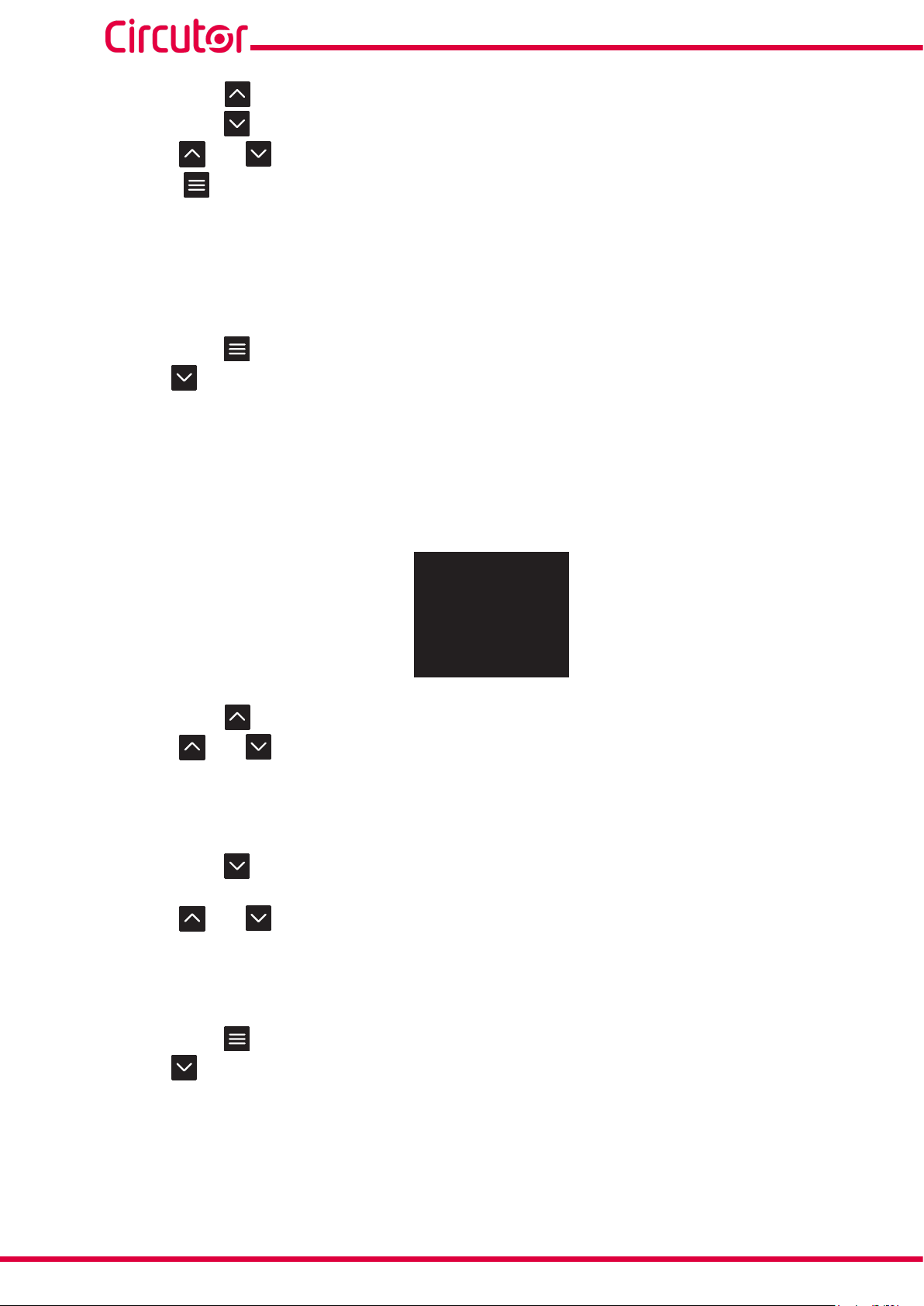
5.4.- CONFIGURATION line-M-4IO-T
Configuration via display of the line-M-4IO-T expansion module is carried out via line-CVM to which
it is connected.
To access the configuration menu, hold down (>2s) key .
LIII
INST
SETUP
SETUP
PROG
AVG
AVG
SETUP
SETUP
230.00
5.00
50.00
1.00
PRIMARY VT
1.0
V
SECONDARY VT
1.00
MODE
IMPULSE
NAME
IN1
D IN1
MODE
IMPULSE
NAME
IN1
D IN2
MODE
IMPULSE
NAME
IN1
D IN3
V
A
Hz
cos
T1
MEASURE, Measurement parameters
V
MEASURE
D IN1, Digital Input 1
SLOT1
D IN2, Digital Input 2
SLOT1
CLOCK
D IN3, Digital Input 3
SLOT1
SETUP
SETUP
SETUP
SETUP
PROG
PROG
SETUP
PROG
MODE
IMPULSE
NAME
IN1
D IN4
VARIABLE
1 V1
D OUT1
VARIABLE
1 V1
D OUT2
VARIABLE
1 V1
D OUT3
VARIABLE
1 V1
D OUT4
SLOT1
SLOT1
OUT2
SLOT1
kgCO2
SLOT1
OUT1
SLOT1
OUT1
D IN4, Digital Input 4
D OUT1, Transistor output 1
D OUT2, Transistor output 2
VARIABLE
VARIABLE
PROG
D OUT3, Transistor output 3
D OUT4, Transistor output 4
Expansion module line-M-4IO-T
Instruction Manual
Figure 16: Configuration menu.
41
Page 42

line-M
Note: SLOT1 is the expansion module nearest line-CVM, SLOT2 is the following expansion module.
To exit the configuration menu, hold down (>2s) key .
5.4.1.- CONFIGURATION OF DIGITAL INPUTS 1 ... 4
Note: Digital input x configuration is identified by the literal D INx at the bottom centre of the display.
See Digital Input Configuration in section"4.4.1.- CONFIGURATION OF DIGITAL INPUTS 1 ... 4."
5.4.2.- CONFIGURATION OF TRANSISTOR OUTPUTS 1 ... 4
Note: Transistor output x configuration is identified by the literal D OUTx at the bottom centre of the
display.
Transistor output configuration is the same as relay output configuration, see "4.4.2.- CONFIGURATION
OF RELAY OUTPUTS 1 ... 4."
5.5.- MODBUS MEMORY MAP line-M-4IO-T
Note: For all modbus map parameters, SLOT1 corresponds to the first expansion module connected to
the right-hand side of the line-CVM-D and SLOT2 corresponds to the second connected module.
5.5.1.- INPUT AND OUTPUT STATUS
See input and output status addresses in section "4.5.1.- INPUT AND OUTPUT STATUS"
5.5.2.- PULSE METERS
See input and output status addresses in section "4.5.2.- IMPULSE METERS"
5.5.3.- ALARMS
See alarm activation date addresses in section "4.5.3.- ALARMS"
5.5.4.- DEVICE CONFIGURATION VARIABLES
5.5.4.1.- Digital Input Configuration
42
See Digital Input Configuration Addresses in section "4.5.4.1.- Digital Input Configuration”
5.5.4.2.- Transistor Output Configuration
Transistor output configuration addresses are the same as those for relay outputs, see section
"4.5.4.2.- Relay Output Configuration".
Instruction Manual
Page 43

line-M
5.6.- TECHNICAL FEATURES: line-M-4IO-T
General features
Maximum power of the module
3 W
Installation category CAT III 300V
Refresh time
Response time (outputs)/Detection time (inputs)
(17)
With the module connected to a line-CVM.
(17)
(17)
200 ms
< 200 ms
Digital inputs
Quantity 4
Type Optocoupled
Insulation 3750 V ~
Input impedance 3 kΩ
Digital transistor outputs
Quantity 4
Type Optocoupled (Open-Collector)
Maximum voltage 48 V
Maximum current 120 mA
Maximum frequency 500 Hz
Pulse width 1 ms
User interface
LED 9 LEDs
Environmental features
Operating temperature -10ºC ... + 50ºC
Storage temperature -20ºC ... +70ºC
Relative humidity (non-condensing) 5... 95%
Maximum altitude 2000 m
Protection degree IP30, Front: IP40,
Mechanical features
Terminals
1... 12, 19... 24 2.5 mm
2
≤ 0.4 Nm, M2.5 flat
Dimensions Figure 12 (mm)
Weight 155 g.
Enclosure
Attachment DIN rail
(18)
Recommended minimum distance between DIN rails: 150 mm
Self-extinguishing V0 plastic
(18)
Standards
Safety requirements for electrical equipment for measurement, control, and laboratory use
Part 1: General requirements.
Electromagnetic compatibility (EMC) Part 6-2: General standards. Immunity for industrial
environments.
Electromagnetic Compatibility (EMC) Part 6-4: General standards. Emission standard for
industrial environments. (IEC 61000-6-4: 2006).
Safety Requirements for Electrical Equipment for Measurement, Control, and Laboratory
Use - Part 1: General Requirements
En 61010-1
EN 61000-6-2
EN 61000-6-4
UL 61010-1
Instruction Manual
43
Page 44

6 . line-M-4IO-A
The line-M-4IO-A expansion module has 4 analogue inputs and outputs.
line-M
6.1.- DEVICE TERMINALS
1: 1, Analogue input 1 7, 8: GND, Common analogue outputs
2: 2, Analogue input 2 9: 4, Analogue output 4
3: 3, Analogue input 3 10: 3, Analogue output 3
4: 4, Analogue input 4 11: 2, Analogue output 2
5, 6: GND, Common analogue inputs 12: 1, Analogue output 1
12
11
10
9
8
7
Figure 17: Line-M-4IO-A terminals: Upper - Lower.
Table 23: List of line-M-410-A terminals.
Device terminals
1
2
3
4
5
6
44
Instruction Manual
Page 45

line-M
6.2. - CONNECTION DIAGRAM
Entradas analógicas
Analog inputs
Sensor
0/4 ...20 mA
+
-
1
150Ω
IN
Salidas analógicas
Analog outputs
6 12
D
A
D
A
line-M-4IO-A
OUT
Carga externa
External load
Figure 18: Line-M-4IO-A connection diagram.
6.3 .- LED INDICATORS
IN 1
IN 2
IN 3
IN 4
CPU
Figure 19: LEDs: line-M-4IO-A.
The line-M-4IO-A have 9 indicating LEDs:
line-M-4IO-A
OUT 1
IN
OUT
OUT 2
OUT 3
OUT 4
Instruction Manual
45
Page 46

CPU, Indicates device status:
LED Description
CPU
Flashing:
White: Indicates that the device is powered
IN x, Indicates analogue input x status:
LED Description
IN x
On:
Green: Indicates activated x input
OUT x, Indicates analogue output x status:
Table 26: LED OUT x.
LED Description
OUT x
On:
Red: Indicates activated x output
line-M
Table 24: CPU LED.
Table 25: Led IN x.
46
Instruction Manual
Page 47

line-M
6.4.- CONFIGURATION Line-M-410-A
Configuration via display of the line-M-4IO-A is carried out via line-CVM to which it is connected.
To access the configuration menu, hold down (>2s) key .
LIII
INST
SETUP
SETUP
SETUP
SETUP
AVG
AVG
230.00
5.00
50.00
1.00
PRIMARY VT
1.0
SECONDARY VT
1.00
NAME
INPUT1
SCALE
0..20mA
A IN1
NAME
INPUT1
SCALE
0..20mA
A IN2
NAME
INPUT1
SCALE
0..20mA
A IN3
V
A
Hz
cos
T1
V
MEASURE, Measurement parameters
V
MEASURE
A IN1, Analogue input 1
SLOT2
A IN2, Analogue input 2
SLOT2
A IN3, Analogue input 3
SLOT2
SETUP
SETUP
SETUP
SETUP
SETUP
NAME
INPUT1
SCALE
0..20mA
A IN4
VARIABLE
1 V1
SCALE
0..20mA
A OUT1
VARIABLE
1 V1
SCALE
0..20mA
A OUT2
VARIABLE
1 V1
SCALE
0..20mA
A OUT3
VARIABLE
1 V1
SCALE
0..20mA
A OUT4
SLOT2
SLOT2
SLOT2
SLOT2
SLOT2
A IN4, Analogue input 4
Lore
A OUT1, Analogue output 1
A OUT2, Analogue output 2
VARIABLE
VARIABLE
PROG
A OUT3, Analogue output 3
A OUT4, Analogue output 4
Expansion module line-M-4IO-A
Instruction Manual
Figure 20: Configuration menu.
47
Page 48

line-M
Note: SLOT1 is the expansion module nearest line-CVM, SLOT2 is the following expansion module.
To exit the configuration menu, hold down (>2s) key .
6.4.1.- CONFIGURATION OF ANALOGUE INPUTS 1 ... 4
Note: Analogue input x configuration is identified by the literal A INx at the bottom centre of the dis-
play.
6.4.1.1 .- Analogue input x Name and Scale
This screen enables the name of analogue input X and its scale to be configured.
NAME
INPUT1
SCALE
0..20mA
SETUP
A IN1
SLOT2
Hold down key to set input name (NAME).
Use keys and to modify the digit's value.
Press key to skip through the digits.
Hold down key to set the scale (SCALE).
Use keys and to skip through the different options:
0..20 mA, Analogue input scale 0.. 20 mA.
4.. 20 mA, Analogue input scale 4 .. 20 mA.
To validate the option, hold down key .
Use key to skip to the next programming point.
6.4.1.2.- Zero and Full Scale
This screen enables configuration of the analogue input's Zero and Full Scale.
48
ZERO
0
FULL SCALE
0
SETUP
A IN1
SLOT2
Hold down key to set zero (ZERO), whose initial analogue input value is 0 or 4 mA.
Hold down key to set full scale (FULL SCALE),whose final analogue input value is 20 mA.
Use keys and to modify the digit's value.
Instruction Manual
Page 49

line-M
Press key to skip through the digits.
Zero and Full Scale:
Minimum value: - 32765.
Maximum value: 32765.
Hold down key to validate the value.
Use key to skip to the next programming point.
6.4.1.3.- Units and decimal No.
This screen enables configuration of the analogue input's units and number of decimals.
UNITS
A
DECIMALS
0
SETUP
A IN1
SLOT2
Hold down key to set the Units (UNITS) for the analogue input.
Hold down key to set the number of decimals (DECIMALS) for the analogue input.
Use keys and to modify the digit's value.
Press key to skip through the digits.
No. of decimals:
Minimum value: 0.
Maximum value: 5.
Hold down key to validate the value.
Use key to skip to the next programming point.
Instruction Manual
49
Page 50

line-M
6.4.2.- CONFIGURATION OF ANALOGUE OUTPUTS 1 ... 4
Note: Analogue output x configuration is identified by the literal A OUTx at the bottom centre of the
display.
6.4.2.1 .- Variable and Scale
This screen enables the analogue output's Variable and Scale to be configured.
VARIABLE
1 V1
SCALE
0..20mA
SETUP
A OUT1
SLOT2
Hold down key to select the analogue output's variable (VARIABLE).
Use keys and to modify the digit's value.
Press key to skip through the digits.
The codes for the variables are shown in Table 9, Table 11 and Table 12.
To validate the option, hold down key .
Hold down key to set the scale (SCALE).
Use keys and to skip through the different options:
0..20 mA, Analogue output scale 0.. 20 mA.
0.. 10 V, Analogue output scale 0.. 10 V.
4.. 20 mA, Analogue output scale 4 .. 20 mA.
To validate the option, hold down key .
Use key to skip to the next programming point.
6.4.2.2.- Zero and Full Scale
50
This screen enables configuration of the analogue output's Zero and Full Scale.
ZERO
0
FULL SCALE
0
SETUP
A OUT1
SLOT2
Hold down key to set zero (ZERO), whose initial analogue output value is 0 mA, 4 mA or 0 V.
Instruction Manual
Page 51

line-M
Hold down key to set full scale (FULL SCALE),whose final analogue output value is 20 mA or 10 V.
Use keys and to modify the digit's value.
Press key to skip through the digits.
Zero and Full Scale:
Minimum value: - 32765.
Maximum value: 32765.
Hold down key to validate the value.
Use key to skip to the next programming point.
6.5.- MODBUS MEMORY MAP line-M-4IO-A
Note: For all modbus map parameters, SLOT1 corresponds to the first expansion module connected to
the right-hand side of the line-CVM-D and SLOT2 corresponds to the second connected module.
6.5.1.- ANALOGUE INPUT
The Function 0x04, is implemented for these variables.
Table 27: Modbus Memory Map: Analogue Input Value.
Parameter Format
Analogue Input Value 1 Int [32] D390 - D391 D778 - D779
Analogue Input Value 2 Int [32] D392 - D393 D77A - D77B
Analogue Input Value 3 Int [32] D394 - D395 D77C - D77D
Analogue Input Value 4 Int [32] D396 - D397 D77E - D77F
SLOT 1 SLOT 2
Address
6.5.2.- DEVICE CONFIGURATION VARIABLES
The following functions are used for these variables:
Function 0x03: register readout.
Function 0x10: Writing multiple registers.
Instruction Manual
51
Page 52

6.5.2.1.- Analogue Input Configuration
Table 28: Modbus Memory Map: Analogue Inputs.
SLOT 1
Analogue Input 1
Parameter Format Address Valid data range Default value
Name String
Scale Uint [16] D2F2 0: 0... 20 mA - 1: 4... 20 mA 0
Zero Value Int [16] D2F0 - 32765... 32765 0
Full Scale Value Int [16] D2F1 - 32765... 32765 0
Units String D2F8 - D2F9 -D2FA - -
Nº of Decimals Uint [16] D2F3 0... 5 0
Analogue Input 2
Name String
Scale Uint [16] D306 0: 0... 20 mA - 1: 4... 20 mA 0
Zero Value Int [16] D304 - 32765... 32765 0
Full Scale Value Int [16] D305 - 32765... 32765 0
Units String D30C- D30D - D30E - -
Nº of Decimals Uint [16] D307 0... 5 0
Analogue Input 3
Name String
Scale Uint [16] D31A 0: 0... 20 mA - 1: 4... 20 mA 0
Zero Value Int [16] D318 - 32765... 32765 0
Full Scale Value Int [16] D319 - 32765... 32765 0
Units String D320- D321 - D322 - -
Nº of Decimals Uint [16] D31B 0... 5 0
Analogue Input 4
Name String
Scale Uint [16] D32E 0: 0... 20 mA - 1: 4... 20 mA 0
Zero Value Int [16] D32C - 32765... 32765 0
Full Scale Value Int [16] D32D - 32765... 32765 0
Units String D334- D335 - D336 - -
Nº of Decimals Uint [16] D32F 0... 5 0
Analogue Input 1
Name String
Scale Uint [16] D6DA 0: 0... 20 mA - 1: 4... 20 mA 0
Zero Value Int [16] D6D8 - 32765... 32765 0
Full Scale Value Int [16] D6D9 - 32765... 32765 0
Units String D6E0-D6E1-D6E2 - -
Nº of Decimals Uint [16] D6DB 0... 5 0
D2F4 - D2F5 -
D2F6 - D2F7
D308-D309 -
D30A-D30B
D31C - D31D -
D31E - D31F
D330-D331 -
D332-D333
D6DC-D6DD -
D6DE-D6DF
-
-
-
-
SLOT 2
-
line-M
-
-
-
-
-
52
Instruction Manual
Page 53

line-M
Table 28 (Continuation): Modbus Memory Map: Analogue Inputs.
Parameter Format Address Valid data range Default value
Analogue Input 2
Name String
Scale Uint [16] D6EE 0: 0... 20 mA - 1: 4... 20 mA 0
Zero Value Int [16] D6EC - 32765... 32765 0
Full Scale Value Int [16] D6ED - 32765... 32765 0
Units String D6F4-D6F5 -D6F6 - -
Nº of Decimals Uint [16] D6EF 0... 5 0
Analogue Input 3
Name String
Scale Uint [16] D702 0: 0... 20 mA - 1: 4... 20 mA 0
Zero Value Int [16] D700 - 32765... 32765 0
Full Scale Value Int [16] D701 - 32765... 32765 0
Units String D708-D709-D70A - -
Nº of Decimals Uint [16] D703 0... 5 0
Analogue Input 4
Name String
Scale Uint [16] D716 0: 0... 20 mA - 1: 4... 20 mA 0
Zero Value Int [16] D714 - 32765... 32765 0
Full Scale Value Int [16] D715 - 32765... 32765 0
Units String D71C-D71D -D71E - -
Nº of Decimals Uint [16] D717 0... 5 0
D6F0-D6F1-D6F2-
D6F3
D704 - D705 - D706
- D707
D718-D719 -
D71A-D71B
-
-
-
-
-
-
6.5.2.2.- Analogue Output Configuration
Table 29: Modbus Memory Map: Analogue outputs.
SLOT 1
Analogue output 1
Configuration parameters Format Address Valid data range Default value
Variable Uint [16] D340 Table 9 - Table 11 - Table 12 0
Scale Uint [16] D345
Zero Value Int [32] D341-D342 - 32765... 32765 0
Full Scale Value Int [32] D343-D344 - 32765... 32765 0
Analogue output 2
Variable Uint [16] D34A Table 9 - Table 11 - Table 12 0
Scale Uint [16] D34F
Zero Value Int [32] D34B-D34C - 32765... 32765 0
Full Scale Value Int [32] D34D-D34E - 32765... 32765 0
Analogue output 3
Variable Uint [16] D354 Table 9 - Table 11 - Table 12 0
0: 0... 20 mA - 1: 4... 20 mA -
2: 0... 10 V
0: 0... 20 mA - 1: 4... 20 mA -
2: 0... 10 V
0
0
Instruction Manual
53
Page 54

line-M
Table 29 (Continuation): Modbus Memory Map: Analogue outputs.
Configuration parameters Format Address Valid data range Default value
Scale Uint [16] D359
Zero Value Int [32] D355-D356 - 32765... 32765 0
Full Scale Value Int [32] D357-D358 - 32765... 32765 0
Analogue output 4
Variable Uint [16] D35E Table 9 - Table 11 - Table 12 0
Scale Uint [16] D363
Zero Value Int [32] D35F-D360 - 32765... 32765 0
Full Scale Value Int [32] D361-D362 - 32765... 32765 0
SLOT 2
Analogue output 1
Variable Uint [16] D728 Table 9 - Table 11 - Table 12 0
Scale Uint [16] D72D
Zero Value Int [32] D729-D72A - 32765... 32765 0
Full Scale Value Int [32] D72B-D72C - 32765... 32765 0
Analogue output 2
Variable Uint [16] D732 Table 9 - Table 11 - Table 12 0
Scale Uint [16] D737
Zero Value Int [32] D733-D734
Full Scale Value Int [32] D735-D736
Analogue output 3
Variable Uint [16] D73C
Scale Uint [16] D741
Zero Value Int [32] D73D-D73E
Full Scale Value Int [32] D73F-D740
Analogue output 4
Variable Uint [16] D746
Scale Uint [16] D74B
Zero Value Int [32] D747-D748
Full Scale Value Int [32] D749-D74A
0: 0... 20 mA - 1: 4... 20 mA -
2: 0... 10 V
0: 0... 20 mA - 1: 4... 20 mA -
2: 0... 10 V
0: 0... 20 mA - 1: 4... 20 mA -
2: 0... 10 V
0: 0... 20 mA - 1: 4... 20 mA -
2: 0... 10 V
- 32765... 32765 0
- 32765... 32765
Table 9 - Table 11 - Table 12
0: 0... 20 mA - 1: 4... 20 mA -
2: 0... 10 V
- 32765... 32765 0
- 32765... 32765
Table 9 - Table 11 - Table 12
0: 0... 20 mA - 1: 4... 20 mA -
2: 0... 10 V
- 32765... 32765 0
- 32765... 32765
0
0
0
0
0
0
0
0
0
0
0
54
Instruction Manual
Page 55

line-M
6.6.- TECHNICAL FEATURES: line-M-4IO-A
General features
Maximum power of the module
3 W
Installation category CAT III 300V
Refresh time
Response time (outputs)/Detection time (inputs)
(19)
With the module connected to a line-CVM.
(19)
(19)
200 ms
< 200 ms
Analogue inputs
Quantity 4
Type of measure Current
Nominal input range 0 - 20 mA, 4 - 20 mA (Programmable)
Input impedance 150 Ω
Permissible maximum current to the input 22 mA
Analogue outputs
Quantity 4
Maximum internal voltage 12 V
Linearity < 1%
DAC resolution 4096 points
Analogue outputs in current mode
Nominal output range 0 - 20 mA, 4 - 20 mA (Programmable)
Maximum load resistance 300 Ω
Analogue outputs in voltage mode
Nominal output range 0 - 10 V
Maximum load resistance 5000 Ω
Accuracy
Inputs Outputs
0... 20 mA 0... 20 mA 0... 10 V
Accuracy < 1 % 1% 1%
Accuracy range in relation to Full Scale 5... 100% 0,5... 100% 2... 100%
Measurement range in relation to Full Scale 1... 100% 0,1... 100% 0,2... 100%
User interface
LED 9 LEDs
Environmental features
Operating temperature -10ºC ... + 50ºC
Storage temperature -20ºC ... +70ºC
Relative humidity (non-condensing) 5... 95%
Maximum altitude 2000 m
Protection degree IP30, Front: IP40,
Mechanical features
Terminals
1... 12, 2.5 mm
2
≤ 0.4 Nm, M2.5 flat
Dimensions Figure 12 (mm)
Weight 153 g.
Instruction Manual
55
Page 56

(Continuation) Mechanical features
Enclosure Self-extinguishing V0 plastic
Attachment DIN rail
(20)
Recommended minimum distance between DIN rails: 150 mm.
(20)
Standards
Safety requirements for electrical equipment for measurement, control, and laboratory use
Part 1: General requirements.
Electromagnetic compatibility (EMC) Part 6-2: General standards. Immunity for industrial
environments.
Electromagnetic Compatibility (EMC) Part 6-4: General standards. Emission standard for
industrial environments. (IEC 61000-6-4: 2006).
Safety Requirements for Electrical Equipment for Measurement, Control, and Laboratory
Use - Part 1: General Requirements
line-M
En 61010-1
EN 61000-6-2
EN 61000-6-4
UL 61010-1
56
Instruction Manual
Page 57

line-M
7. line-M-4IO-RV
The line-M-4IO-RV expansion module has 4 digital inputs in voltage at 230 V~ and 4 relay outputs.
7.1.- DEVICE TERMINALS
12
11
10
9
8
7
1: C, Common digital inputs 11: C, Relay output 1 (Common)
2: 1, Digital input 1 12: NC, Relay output 1 (NC)
3: 2, Digital input 2 19: NO, Relay output 4 (NO)
4: 3, Digital input 3 20: C, Relay output 4 (Common)
5: 4, Digital input 4 21: NC, Relay output 4 (NC)
7: NO, Relay output 2 (NO) 22: NO, Relay output 3 (NO)
8: C, Relay output 2 (Common) 23: C, Relay output 3 (Common)
9: NC, Relay output 2 (NC) 24: NC, Relay output 3 (NC)
10: NO, Relay Output 1 (NO)
1
2
3
4
5
Figure 21: Line-M-4IO-RV terminals: Upper - Lower.
Table 30: List of line-M-410-RV terminals.
Device terminals
24
23
22
21
20
19
Instruction Manual
57
Page 58

7.2. - CONNECTION DIAGRAM
Entradas digitales
Digital inputs
1 2 3 4
L
line-M
N
230 V~
1
C
1
2
3
4
6 12
140k
Relé 2
Relay 2
line-M-4IO-RV
IN
OUT
Relé 1
Relay 1
1
2
3
4
Relé 4
Relay 4
19
Relé 3
Relay 3
24
Figure 22: Line-M-4IO-RV connection diagram.
58
Instruction Manual
Page 59

line-M
7.3 .- LED INDICATORS
line-M-4IO-RV
IN 1
IN 2
IN 3
IN 4
CPU
IN
Figure 23: LEDs: line-M-4IO-RV.
OUT
OUT 1
OUT 2
OUT 3
OUT 4
The line-M-4IO-RV have 9 indicating LEDs:
CPU, Indicates device status:
LED Description
CPU
Flashing:
White: Indicates that the device is powered
IN x, Indicates digital input x status:
LED Description
IN x
On:
Green: Indicates activated input
OUT x, Indicates relay output x status:
Table 31: CPU LED.
Table 32: Led IN x.
Table 33: LED OUT x.
Instruction Manual
LED Description
OUT x
On:
Red: Indicates activated x output
59
Page 60

line-M
7.4.- CONFIGURATION line-M-4IO-RV
Configuration via display of the line-M-4IO-RV is carried out via line-CVM to which it is connected.
To access the configuration menu, hold down (>2s) key .
AVG
AVG
LIII
INST
SETUP
SETUP
PROG
SETUP
SETUP
230.00
5.00
50.00
1.00
PRIMARY VT
1.0
SECONDARY VT
1.00
MODE
STATUS
NAME
IN1
D IN1
MODE
STATUS
NAME
IN1
D IN2
MODE
STATUS
NAME
IN1
D IN3
V
A
Hz
cos
T1
V
MEASURE, Measurement parameters
V
MEASURE
D IN1, Digital Input 1
SLOT1
D IN2, Digital Input 2
SLOT1
CLOCK
D IN3, Digital Input 3
SLOT1
SETUP
SETUP
SETUP
SETUP
PROG
PROG
SETUP
PROG
MODE
STATUS
NAME
IN1
D IN4
VARIABLE
1 V1
D OUT1
VARIABLE
1 V1
D OUT2
VARIABLE
1 V1
D OUT3
VARIABLE
1 V1
D OUT4
SLOT1
SLOT1
OUT2
kgCO2
SLOT1
OUT1
SLOT1
SLOT1
OUT1
D IN4, Digital Input 4
D OUT1, Relay output 1
D OUT2, Relay output 2
VARIABLE
VARIABLE
PROG
D OUT3, Relay output 3
D OUT4, Relay output 4
Expansion module line-M-4IO-RV
60
Figure 24: Configuration menu.
Instruction Manual
Page 61

line-M
Note: SLOT1 is the expansion module nearest line-CVM, SLOT2 is the following expansion module.
To exit the configuration menu, hold down (>2s) key .
7.4.1.- CONFIGURATION OF DIGITAL INPUTS 1 ... 4
Note: Digital input x configuration is identified by the literal D INx at the bottom centre of the display.
See Digital Input Configuration in section "4.4.1.- CONFIGURATION OF DIGITAL INPUTS 1 ... 4."
7.4.2.- CONFIGURATION OF RELAY OUTPUTS 1 ... 4
Note: Relay output x configuration is identified by the literal D OUTx at the bottom centre of the display.
See Relay Output Configuration in section "4.4.2.- CONFIGURATION OF RELAY OUTPUTS 1 ... 4."
7.5.- MODBUS MEMORY MAP Line-M-410-RV
Note: For all modbus map parameters, SLOT1 corresponds to the first expansion module connected to
the right-hand side of the line-CVM-D and SLOT2 corresponds to the second connected module.
7.5.1.- INPUT AND OUTPUT STATUS
See input and output status addresses in section "4.5.1.- INPUT AND OUTPUT STATUS"
7.5.2.- ALARMS
See alarm activation date addresses in section "4.5.3.- ALARMS"
7.5.3.- DEVICE CONFIGURATION VARIABLES
7.5.3.1.- Digital Input Configuration
See Digital Input Configuration Addresses in section "4.5.4.1.- Digital Input Configuration”
7.5.3.2.- Relay Output Configuration
See Relay Output Configuration Addresses in section "4.5.4.2.- Relay Output Configuration".
Instruction Manual
61
Page 62

7.6.- TECHNICAL FEATURES: Line-M-410-RV
General features
Maximum power of the module 2 W
Installation category CAT III 300V
Refresh time
Response time (outputs)/Detection time (inputs)
(21)
With the module connected to a line-CVM.
(21)
(21)
200 ms
< 200 ms
Digital inputs
Quantity 4
Type Mains voltage input 230 V~
Maximum current 50 mA
Insulation 3750 V ~
Input impedance 140 kΩ
Digital relay outputs
Quantity 4
Type Electronic class A - High Frequency Current Filtering
Maximum switching voltage 250 V ~
Maximum instantaneous current 6 A ~
Maximum switching power 1500 VA
Electrical life (maximum load) 5x10⁴ cycles
Mechanical life 5x10⁶ cycles
Protection Contacts protected by varistor (Maximum voltage: 275 V~)
line-M
User interface
LED 9 LEDs
Environmental features
Operating temperature -10ºC ... + 50ºC
Storage temperature -20ºC ... +70ºC
Relative humidity (non-condensing) 5... 95%
Maximum altitude 2000 m
Protection degree IP30, Front: IP40,
Mechanical features
Terminals
1... 5, 7... 12, 19... 24 2.5 mm
2
≤ 0.4 Nm, M2.5 Flat
Dimensions Figure 12 (mm)
Weight 215 g.
Enclosure Self-extinguishing V0 plastic
Attachment DIN rail
(22)
Recommended minimum distance between DIN rails: 150 mm.
(22)
Standards
Safety requirements for electrical equipment for measurement, control, and laboratory use
Part 1: General requirements.
Electromagnetic compatibility (EMC) Part 6-2: General standards. Immunity for industrial
environments.
Electromagnetic Compatibility (EMC) Part 6-4: General standards. Emission standard for
industrial environments. (IEC 61000-6-4: 2006).
EN 61010-1
EN 61000-6-2
EN 61000-6-4
62
Instruction Manual
Page 63

line-M
(Continuation) Standards
Safety Requirements for Electrical Equipment for Measurement, Control, and Laboratory
Use - Part 1: General Requirements
UL 61010-1
Instruction Manual
63
Page 64

8. Line-M-EXT-PS
The Line-M-EXT-PS is a power adapter for the Line family of devices.
The module is connected to the left side of the device you wish to supply.
line-M
8.1.- INSTALLATION
The Line-M-EXT-PS connects to the left-hand side of the devices you wish to supply. It can supply up
to 10 VA, allowing it to power a limited number of devices.
The maximum set it can supply is: 1 line-EDS 1 line-CVM + 1 line-M (Figure 25).
line-M-EXT-PS
Figure 25: Maximum set a line-M-EXT-PS can supply.
line-EDS line-M
line-CVM
Multiple Line-M-EXT-PS to supply sets with power above 10VA. Each Line-M-EXT-PS will power the
devices connected to its right-hand side (Figure 26).
64
line-M-EXT-PS
line-EDS line-M line-M
Figure 26: Multiple line-M-EXT-PS connection.
line-M-EXT-PS
line-CVM
line-M line-M
line-M-EXT-PS
line-CVM line-CVM
Note: The line-EDS and line-CVM devices, must not be connected to the auxiliary power supply.
Instruction Manual
Page 65

line-M
8.2.- DEVICE TERMINALS
11
9
Figure 27: Line-M-EXT-PS terminals.
8.3. - CONNECTION DIAGRAM
8.3.1.- MAXIMUM CONNECTION
Alimentación Auxiliar
Power Supply
A1
9
11
~ / +
~ / -
line-M-EXT-PS
A2
Table 34: List of line-M-EXT-PS terminals.
Device terminals
9: A1 ~ / + , Auxiliary power supply
11: A2 ~ / - , Auxiliary power supply
WLAN
LAN
line-EDS
SLAVES
line-CVM-D32
line-M-4IO-A
IN
OUT
Instruction Manual
DC
Figure 28: Maximum connection.
65
Page 66

8.3.2.- MULTIPLE CONNECTION Line-M-EXT-PS
line-M
Alimentación Auxiliar
Power Supply
9
11
8.4. - LED INDICATORS
~ / +
~ / -
line-M-EXT-PS
DC
A1
A2
WLAN
LAN
line-EDS
SLAVES
Alimentación Auxiliar
line-CVM-D32
Power Supply
9
11
line-M-4IO-A
IN
OUT
~ / +
~ / -
line-M-EXT-PS
DC
A1
A2
1
2
IN
3
4
Figure 29: Multiple line-M-EXT-PS connection.
line-M-4IO-T
OUT
1
2
3
4
line-CVM-D32
line-M-4IO-T
1
2
IN
3
4
1
2
OUT
3
4
Figure 30: LEDs: line-M-EXT-PS.
The Line-M-EXT-PS have 1 indicating LED:
CPU, Indicates device status:
Table 35: LEDs line-M-EXT-PS.
LED Description
CPU
Flashing:
Green: Indicates that the device is powered
line-M-EXT-PS
DC
CPU
66
Instruction Manual
Page 67

line-M
8.5. - TECHNICAL FEATURES: Line-M-EXT-PS
Power supply
Input
AC power supply
Rated voltage 110... 277 V~ (Ph - N) / 110 ... 480 V~ (Ph - Ph)
Frequency 50... 60 Hz
Consumption 1... 9 VA
Installation category CAT III 300V
Output
Maximum output voltage 12 V
Maximum output current 0.9 A
Maximum output power 10 VA
User interface
LED 1 LED
Environmental features
Operating temperature -10ºC ... + 50ºC
Storage temperature -20ºC ... +70ºC
Relative humidity (non-condensing) 5... 95%
Maximum altitude 2000 m
Protection degree IP30, Front: IP40
Mechanical features
Terminals
9, 11 2.5 mm
2
≤ 0.4 Nm, M2.5 flat
Dimensions Figure 12 (mm)
Weight 350 g.
Enclosure Self-extinguishing V0 plastic
Attachment DIN rail
(23)
Recommended minimum distance between DIN rails: 150 mm.
(23)
Standards
Safety requirements for electrical equipment for measurement, control, and laboratory use
Part 1: General requirements.
Safety requirements for electrical equipment for measurement, control, and laboratory use
Part 2-030: Specific requirements for test and measuring circuits.
Electrical material for measurement, control and laboratory use Electromagnetic compatibility (EMC) requirements Part 1: General requirements
EN 61010-1
EN 61010-2-030
EN 61326-1
Electromagnetic compatibility of multimedia equipment. Emission requirements. EN 55032
UL 94
Audio/video, information and communication technology equipment. Part 1: Safety requirements
EN 62368-1
Instruction Manual
67
Page 68

9. line-M-3G
The line-M-3G module adds 3G connectivity to the line-EDS device to which it is connected.
The module is connected laterally to the left of the line-EDS devices.
line-M
9.1.- INSTALLATION OF THE SIM CARD
Before installing the SIM card, the module must be disconnected from any power
source.
The slot for inserting the SIM card is at the back of the device, Figure 31.
TARJETA SIM
SIM CARD
68
Figure 31: SIM card position.
Instruction Manual
Page 69

line-M
9.2.- LED INDICATORS
CONNECTED
SIGNAL
SIM
CPU
The line-M-3G have 4 indicating LEDs:
CPU, Indicates device status:
LED Description
CPU
Flashing:
White: Indicates that the device is powered
CONNECTED
SIGNAL
SIM
Figure 32: LEDs: line-M-3G.
Table 36: LED CPU.
CONNECTED, Indicates the connection status:
Table 37: LED CONNECTED.
LED Description
Flashing:
CONNECTED
Blue color: Indicates that connection has been made, has registered to the network
SIGNAL, Indicates the 3G coverage:
Table 38: LED SIGNAL.
LED Description
SIGNAL
On:
Blue color: Indicates that 3G coverage is ≥ 25%
SIM, Indicates the status of the SIM card:
Table 39: LED SIM.
LED Description
On:
SIM
Red color: Indicates that the device does not have the SIM card
installed.
Instruction Manual
69
Page 70

line-M
9.3.- COMMUNICATIONS
9.3.1.- USAGE ENVIRONMENT AND HEALTH
Wireless communications emit radio frequency electromagnetic energy, like other radio devic es.
Because wireless communications operate under the guidelines found in radio frequency stand ards
and recommendations, they are safe for users to use.
In some settings and situations the use of wireless communications may be restricted by the building’s
owner of representatives of the organisation.
These may include:
Use of wireless connections on board aircraft, in hospitals or near service stations, blast ing areas,
medical implants or electronic medical devices implanted in the human body (pacemakers, etc.).
In any other setting where the risk of interference with other devices or services is a haz ard.
If you are not sure of the applicable usage policy for wireless devices in a specific organisation (airport,
hospital, etc.) we recommend requesting permission to use wireless communications.
9.3.2.- 3G COMMUNICATIONS
The line-M-3G adds 3G connectivity to the line-EDS devices connected to it, which allows connection
to the devices and the exchange of data with other mobile devices without the need for a Wi-Fi
connection. All that is needed is a SIM card.
The 3G communications have to be set up on the line-EDS configuration website. Check the M231B01-
03-xxx manual.
70
Instruction Manual
Page 71

line-M
9.4.- TECHNICAL FEATURES: line-M-3G
Power supply
Mode Through the line-EDS devices
AC consumption 2.8 ... 4.1 VA
ADC consumption 1.9 ... 2.2 W
Installation category CAT III 300V
3G communications
Networks
UMTS/HSPA+: 800/850/900/1900/2100 MHz
GSM/GPRS/EDGE: 850/900/1800/1900 MHz
Protocols PPP/TCP/UDP/FTP/HTTP/MMS/SMTP/SSL
UTMS (Class 3): 24 dBm + 1 dB / - 3dB
EDGE 850/900 (Class E2): 27 dBm ± 3dB
Max. output power
EDGE 1800/1900 (Class E2): 26 dBm + 3dB / - 4dB
GSM 850/900 (Class 4): 33 dBm ± 2dB
GSM 1800/1900 (Class 1): 30 dBm ± 2dB
Antenna
Band 850 / 900 MHz 1700 / 1800 / 1900 / 2100 MHz
Frequency 824 ... 960 MHz 1710 ... 2170 MHz
Return loss ~ 8.6 dB ~ 89.4 dB
VSWR ~ 2.2:1 ~ 2.4:1
Efficiency ~ 70.6 % ~ 56.4 %
Peak gain ~ 2.9 dBi ~ 1.8 dBi
Average gain ~ -1.5 dB ~ - 2.5 dB
Impedance 50 Ω
Polarisation Linear
Radiation pattern Omni-directional
Maximum input power 25 W
Connector type SMA - Male standard (Right - Angle)
SIM card
Type Micro SIM
User interface
LED 4 LEDs
Environmental features
Operating temperature -10ºC ... +50ºC
Storage temperature -20ºC ... +70ºC
Relative humidity (non-condensing) 5 ... 95%
Maximum altitude 2000 m
Protection degree IP30, Front: IP40
Mechanical features
Dimensions
Weight
Version 1.0: Figure 12 (mm)
Version 2.0: Figure 33 (mm)
Version 1.0: 150 g.
Version 2.0: 130 g.
Enclosure Self-extinguishing V0 plastic
Attachment DIN rail
(24)
Recommended minimum distance between DIN rails: 150 mm.
(24)
Instruction Manual
71
Page 72

Standards
Safety requirements for electrical equipment for measurement, control, and laboratory use
Part 1: General requirements.
Electromagnetic compatibility (EMC) Part 6-2: General standards. Immunity for industrial
environments.
Electromagnetic Compatibility (EMC) Part 6-4: General standards. Emission standard for
industrial environments. (IEC 61000-6-4: 2006).
88.95
70
35 44
line-M
EN 61010-1
EN 61000-6-2
EN 61000-6-4
93.85
90
35.7
Figure 33: line-M-3G dimensions: Version 2.0.
45
72
Instruction Manual
Page 73

line-M
10. line-TCPRS1
The line-TCPRS1 is a gateway designed to convert an RS-485 or RS-232 physical environment to
Ethernet and/or Wi-Fi. The device features a Web Server and an app, MyConfig (Android), that uses
Bluetooth connectivity®, from which the user can completely edit the configuration parameters of the
device.
The device can be connected via the side bus with up to 7 devices of the line range: line-CVM-D32 and
line-M-xxx-xx expansion modules. It also has RS-485 and RS-232 communication terminals (external
bus) so that it can be simultaneously connected to other devices not in the line range.
Note: The peripheral numbers of the devices connected via the side bus are: 2, 3, 4... successively and
in order. There may be conflicts and/or collisions if devices are connected to the external bus with
peripheral numbers between 2 and 8.
Note: Peripheral number 1 can be used on the external bus.
Note: For ModbusTCP and TCP protocols, the line-TCPRS1 can be queried for up to 5 Masters at the
same time.
10.1.- INSTALLATION
The device must be connected to a power circuit that is protected with gl (IEC 269) or M type fuses
with a rating of 1 to 2 A. It must be fitted with a circuit breaker or equivalent device, in order to be able
to disconnect the device from the power supply network.
The power and voltage measuring circuit must be connected with cables that have a minimum crosssection of 1mm2.
10.2.- DEVICE TERMINALS
24
11
Ethernet
9
23
22
21
20
Instruction Manual
19
Figure 34: line-TCPRS1 terminals: Upper - lower.
73
Page 74

line-M
Table 40: List of line-TCPRS1 terminals.
Device terminals
9: A1 ~/+, Power supply 22: B-, RS-485
11: A2 ~/-, Power supply 23: S, GND for RS-485
19: Common, GND for RS-232 24: A+, RS-485
20: Rx, RS-232 Ethernet: Ethernet connection
21: Tx, RS-232
Note: For the correct operation of serial communications, the RS-485 and RS-232 ports should not be
wired at the same time.
10.3.- LED INDICATORS
WLAN
LAN
Bluetooth
CPU
The line-TCPRS1 have 7 indicating LEDs:
CPU, Indicates device status:
LED Description
CPU
Flashing:
White: Indicates that the device is powered
RX
TX
Alarma
Alarm
Figure 35: LEDs: line-TCPRS1.
Table 41: LED CPU.
74
WLAN, Indicates the status of Wi-Fi connectivity:
Table 42: LED WLAN.
LED Description
WLAN
On:
Blue color: Indicates that the Wi-Fi connection is activated
LAN, Indicates the status of Ethernet connectivity:
Table 43: LED LAN.
LED Description
LAN
On:
Green color: Indicates that the Ethernet connection is activated
Instruction Manual
Page 75

line-M
Bluetooth, Indicates the status of Bluetooth® connectivity:
Table 44: LED Bluetooth.
LED Description
Bluetooth
On:
Blue color: Bluetooth® linked
RX, TX, Indicates the status of RS-485 / RS-232 communications:
Table 45: LEDs RX and TX.
LED Description
RX
TX
Flashing:
Orange color: Indicates the frame reception
Flashing:
Orange color: Indicates the frame delivery
Alarm, Indicates that an alarm has been generated:
Table 46: LED Alarm.
LED Description
Alarm
10.4.- COMMUNICATIONS
On:
Red color: Frame reception error
10.4.1.- USAGE ENVIRONMENT AND HEALTH
See section “9.3.1.- USAGE ENVIRONMENT AND HEALTH”.
10.4.2.- Wi-Fi COMMUNICATIONS
Wi-Fi is one of the most widespread wireless technologies today. It is used to connect electronic
devices and exchange information between them without having to connect them physically.
The line-TCPRS1 devices feature Wi-Fi communications in the 2.4GHz band, and are compliant with the
IEEE 802.11b, IEEE 802.11g and IEEE 802.11n standards.
10.4.3.- Bluetooth® COMMUNICATIONS
The device features Bluetooth® wireless communication.
Bluetooth® is a short-range wireless technology that allows wireless data transfers between devices
within a range of approximately 10 metres.
10.4.4.- CONFIGURATION WEBSITE
To access the internal configuration website, the device’s IP address has to be entered into the browser
address bar. The line-TCPRS1 is set by default to DHCP mode.
The IP address can be obtained via Bluetooth® using the MyConfig application. The device can be
identified by its MAC address using software such as Advanced IP Scanner or IP Setup Program.
Instruction Manual
75
Page 76

The website of the device can be used to:
On the Device Info screen, view the device’s information and settings for Ethernet, Blue-
tooth®, Wi-Fi and RS-485/RS-232 communications (Figure 36).
line-M
76
Figure 36: Website: Device Info.
Instruction Manual
Page 77

line-M
On the Communications screen, edit the Ethernet and Wi-Fi communications settings (Figure
37).
Figure 37: Website: Communications.
On the Settings screen, edit the RS-485/RS-232 communications settings (Figure 38).
Instruction Manual
Figure 38: Website: Settings.
77
Page 78

On the Firmware screen, update the device’s firmware (Figure 39).
10.4.5.- MOBILE APP
line-M
Figure 39: Website: Firmware.
The MyConfig mobile app, which can be used to set up Wi-Fi and Ethernet communications via
Bluetooth®, can be downloaded free of charge from Google Play (Android).
78
Instruction Manual
Page 79

line-M
10.5.- TECHNICAL FEATURES: line-TCPRS1
AC Power supply
Rated voltage 80 ... 264 V~
Frequency 50 ... 60 Hz
Consumption 3.5 ... 7.5 VA
Installation category CAT III 300V
DC Power supply
Rated voltage 100 ... 300 V
Consumption 2 ... 2.5 W
Installation category CAT III 300V
RS-485 interface
Bus RS-485
Baud rate 4800 - 9600 - 19200 - 38400 - 57600 - 115200 bps
Data bits 7 - 8
Stop bits 1 - 2
Parity without - even - odd
RS-232 interface
Bus RS-232
Baud rate 4800 - 9600 - 19200 - 38400 - 57600 - 115200 bps
Data bits 7 - 8
Stop bits 1 - 2
Parity without - even - odd
Ethernet Interface
Type Ethernet 10BaseT - 100BaseTX self-detectable
Connector RJ45
Protocol TCP - UDP - Modbus TCP - HTTP (Web server) - REST
Connection mode to network DHCP ON/OFF (ON by default)
Wi-Fi communication
Band 2.4 GHz (Range: 2.4 ... 2.5 GHz)
Standard IEEE 802.11 b / g , IEEE 802.11 n (up to 150 Mbps)
Max. output power
Bluetooth® communication
Protocols Bluetooth® v4.2 BR/EDR and BLE specification
NZIF receiver with –97 dBm sensitivity
Class-1, class-2 and class-3 transmitter
Radio
Transmitter RF power control range Min: -12 dBm / Max: +12dBm
Adaptive Frequency Hopping (AFH)
Receiver Sensitivity @30.8% PER -97 dBm
IEEE 802.11 b: 20 dBm
IEEE 802.11 n: 14 dBm
User interface
LED 7 LEDs
Environmental features
Operating temperature -10ºC ... +50ºC
Storage temperature -20ºC ... +70ºC
Instruction Manual
79
Page 80

(Continuation) Environmental features
Relative humidity (non-condensing) 5 ... 95%
Maximum altitude 2000 m
Protection degree IP30, Front: IP40
Mechanical features
Terminals
9, 11, 19 ... 24 2.5 mm
2
≤ 0.4 Nm, M2.5 flat
Dimensions Figure 12 (mm)
Weight 170 g.
Enclosure Self-extinguishing V0 plastic
Attachment DIN rail
(25)
Recommended minimum distance between DIN rails: 150 mm.
(25)
Standards
Safety requirements for electrical equipment for measurement, control, and laboratory use
Part 1: General requirements.
Electromagnetic compatibility (EMC) Part 6-2: General standards. Immunity for industrial
environments.
Electromagnetic Compatibility (EMC) Part 6-4: General standards. Emission standard for
industrial environments. (IEC 61000-6-4: 2006).
Safety Requirements for Electrical Equipment for Measurement, Control, and Laboratory
Use - Part 1: General Requirements
line-M
EN 61010-1
EN 61000-6-2
EN 61000-6-4
UL 61010-1
80
Instruction Manual
Page 81

line-M
11. line-M-20I
The line-M-20I is a centraliser with 20 digital inputs that is designed to centralise the logical status of
each signal or to count the number of impulses received at each input.
The device can be connected via the side bus to the devices of the line range: line-TCPRS1 and line-
EDS.
11.1.- INSTALLATION
Only 2 line-M-20I centraliser can be connect to the right of the line-TCPRS1 devices
(without adding the line-M-EXT-PS power adapter).
11.2.- DEVICE TERMINALS
13
12
11
10
1
14
2
15
3
24
23
22
9
8
7
Instruction Manual
16
4
17
5
18
6
Figure 40: line-M-20I terminals: Upper - lower.
21
20
19
81
Page 82

1: C, Common for digital input 1-5 13: C, Common for digital input 11-15
2: 1, Digital input 1 14: 11, Digital input 11
3: 2, Digital input 2 15: 12, Digital input 12
4: 3, Digital input 3 16: 13, Digital input 13
5: 4, Digital input 4 17: 14, Digital input 14
6: 5, Digital input 5 18: 15, Digital input 15
7: 10, Digital input 10 19: 16, Digital input 16
8: 9, Digital input 9 20: 17, Digital input 17
9: 8, Digital input 8 21: 18, Digital input 18
10: 7, Digital input 7 22: 19, Digital input 19
11: 6, Digital input 6 23: 20, Digital input 20
12: C, Common for digital input 6-10 24: C, Common for digital input 16-20
11.3.- CONNECTION DIAGRAM
line-M
Table 47: line-M-20I device terminals.
Device terminals
C
1
Entradas digitales
1 2 3 4
Digital inputs
10 9 8 75 6
6 12
7
3k
3k
C
82
3k
C
13
12 1314 15 16 17 1819 20
11
3k
C
19
24
Figure 41: line-M-20I connection diagram.
Instruction Manual
Page 83

line-M
11.4.- LED INDICATORS
IN 1... 20
CPU
Figure 42: LEDs: line-M-20I.
The line-M-20I have 21 indicating LEDs:
CPU, Indicates device status:
Table 48: LED CPU.
LED Description
CPU
Flashing:
White: Indicates that the device is powered
IN x, Indicates the status of digital input x:
Table 49: LED IN x.
LED Description
IN x
On:
Green color: Indicates that input x is activated
11.5.- MODBUS MEMORY MAP
All the addresses on the MODBUS map are in Hexadecimal.
11.5.1.- DIGITAL INPUTS
The Function 0x02, is implemented for these variables.
Table 50: Modbus Memory Map: Digital inputs status.
Parameter Format Address Value
Status of digital input 1
Status of digital input 2 0001
Status of digital input 3 0002
Status of digital input 4 0003
Instruction Manual
bool
0000
0: Deactivated , 1: Activated
83
Page 84

Table 50 (Continuation): Modbus Memory Map: Digital inputs status.
Parameter Format Address Value
Status of digital input 5
Status of digital input 6 0005
Status of digital input 7 0006
Status of digital input 8 0007
Status of digital input 9 0008
Status of digital input 10 0009
Status of digital input 11 000A
Status of digital input 12 000B
Status of digital input 13 000C
Status of digital input 14 000D
Status of digital input 15 000E
Status of digital input 16 000F
Status of digital input 17 0010
Status of digital input 18 0011
Status of digital input 19 0012
Status of digital input 20 0013
bool
0004
0: Deactivated , 1: Activated
line-M
11.5.2.- PULSE METERS
The Function 0x04: register readout, is implemented for these variables.
Table 51: Modbus Memory Map: Pulse meter.
Parameter Format Address
Pulse counter of digital input 1
Pulse counter of digital input 2 59DC - 59DD - 59DE - 59DF
Pulse counter of digital input 3 59E0 - 59E1 - 59E2 - 59E3
Pulse counter of digital input 4 59E4 - 59E5 - 59E6 - 59E7
Pulse counter of digital input 5 59E8 - 59E9 - 59EA - 59EB
Pulse counter of digital input 6 59EC - 59ED - 59EE - 59EF
Pulse counter of digital input 7 59F0 - 59F1 - 59F2 - 59F3
Pulse counter of digital input 8 59F4 - 59F5 - 59F6 - 59F7
Pulse counter of digital input 9 59F8 - 59F9 - 59FA - 59FB
Pulse counter of digital input 10 59FC - 59FD - 59FE - 59FF
Pulse counter of digital input 11 5A00 - 5A01 - 5A02 - 5A03
Pulse counter of digital input 12 5A04 - 5A05 - 5A06 - 5A07
Pulse counter of digital input 13 5A08 - 5A09 - 5A0A - 5A0B
Pulse counter of digital input 14 5A0C - 5A0D - 5A0E - 5A0F
Pulse counter of digital input 15 5A10 - 5A11 - 5A12 - 5A13
Pulse counter of digital input 16 5A14 - 5A15 - 5A16 - 5A17
Pulse counter of digital input 17 5A18 - 5A19 - 5A1A - 5A1B
Pulse counter of digital input 18 5A1C - 5A1D - 5A1E - 5A1F
Pulse counter of digital input 19 5A20 - 5A21 - 5A22 - 5A23
Pulse counter of digital input 20 5A24 - 5A25 - 5A26 - 5A27
Uint [64]
59D8 - 59D9 - 59DA - 59DB
84
Instruction Manual
Page 85

line-M
Parameter deletion is carried out by Function 05: writing a relay.
Table 52: Modbus Memory Map: Pulse meter deletion.
Deleting parameters Format Address Value to be sent
Deleting the pulse counters Bool 0898 0xFF00
11.5.3.- OTHER DEVICE PARAMETERS
The Function 0x04: register readout, is implemented for these variables.
Table 53: Modbus Memory Map: Other device parameters.
Parameter Format Address
Device ID number Uint [32] F00A - F00B
Device serial number String F000 - F001 -F002 -F003 -F004 -F005 -F006
Firmware version (part 1) Uint [16] C288
Firmware version (part 2) Uint [16] C289
Firmware version revision Uint [16] C28A
Device model String C28C - C28D
11.5.4.- DEVICE CONFIGURATION VARIABLES
The following functions are used for these variables:
Function 0x03: register readout.
Function 0x10: Writing multiple registers.
11.5.4.1.-Digital Input Configuration
Table 54: Modbus Memory Map: Digital Inputs.
Parameter Format Address Valid data range
Digital Input 1: Mode
Digital Input 2: Mode 4FBC
Digital Input 3: Mode 4FC8
Digital Input 4: Mode 4FD4
Digital Input 5: Mode 4FE0
Digital Input 6: Mode 4FEC
Digital Input 7: Mode 4FF8
Digital Input 8: Mode 5004
Digital Input 9: Mode 5010
Digital Input 10: Mode 501C
Digital Input 11: Mode 5028
Digital Input 12: Mode 5034
Digital Input 13: Mode 5040
Digital Input 14: Mode 504C
Digital Input 15: Mode 5058
Digital Input 16: Mode 5064
Int [16]
4FB0
0 : Status input -
>0: Pulse input (energy per pulse)
(26)
Default
value
0
Instruction Manual
85
Page 86

Table 54 (Continuation): Modbus Memory Map: Digital Inputs.
Parameter Format Address Valid data range
Digital Input 17: Mode
Digital Input 18: Mode 507C
Digital Input 19: Mode 5088
Int [16]
5070
0 : Entrada de estado -
>0: Entrada de pulso (energía por
(8)
pulso)
Digital Input 20: Mode 5094
(26)
To configure the Operating Mode as pulse input, this parameter must be set to Energy per pulse (Value > 0).
11.6.- TECHNICAL FEATURES: line-M-20I
DC power supply
Mode Through the connector
Rated voltage 12 V
Consumption 3.5 W
Installation category CAT III 300V
line-M
Default
value
0
Digital inputs
Quantity 20
Type Optocoupler
Insulation 4.2 kV
Input impedance 1.4 kΩ
Consumption
60 mA inputs OFF
240 mA inputs ON
User interface
LED 21 LEDs
Environmental features
Operating temperature -10ºC ... +50ºC
Storage temperature -20ºC ... +70ºC
Relative humidity (non-condensing) 5 ... 95%
Maximum altitude 2000 m
Protection degree IP30, Front: IP40
Mechanical features
Terminals
1 ... 24 2.5 mm
2
≤ 0.4 Nm, M2.5 flat
Dimensions Figure 12 (mm)
Weight 130 g.
Enclosure Self-extinguishing V0 plastic
Attachment DIN rail
(27)
Recommended minimum distance between DIN rails: 150 mm.
(27)
Standards
Safety requirements for electrical equipment for measurement, control, and laboratory use
Part 1: General requirements.
Electromagnetic compatibility (EMC) Part 6-2: General standards. Immunity for industrial
environments.
Electromagnetic Compatibility (EMC) Part 6-4: General standards. Emission standard for
industrial environments. (IEC 61000-6-4: 2006).
EN 61010-1
EN 61000-6-2
EN 61000-6-4
86
Instruction Manual
Page 87

line-M
(Continuation)Standards
Safety Requirements for Electrical Equipment for Measurement, Control, and Laboratory
Use - Part 1: General Requirements
UL 61010-1
Instruction Manual
87
Page 88

line-M
12. line-LM20I-TCP kit
The line-LM20I-TCP kit is a centraliser with 20 digital inputs with a gateway designed to convert an
RS-485 or RS-232 physical environment to Ethernet and/or Wi-Fi.
The device is designed to centralise the logical status of each signal or to count the number of impulses received at each input. The line-LM20I-TCP kit features a Web Server and an app, MyConfig
(Android), that uses Bluetooth® connectivity, from which the user can completely edit the configuration
parameters of the device.
The device also has RS-485 and RS-232 communication terminals so that it can be simultaneously
connected to other devices not in the line range.
Note: The devices connected to the RS-485 or RS-232 communication terminals have to be configured
with a peripheral number ≥ 10.
12.1.- INSTALLATION
The device must be connected to a power circuit that is protected with gl (IEC 269) or M type fuses
with a rating of 1 to 2 A. It must be fitted with a circuit breaker or equivalent device, in order to be able
to disconnect the device from the power supply network.
The power and voltage measuring circuit must be connected with cables that have a minimum
cross-section of 1mm2.
88
Instruction Manual
Page 89

line-M
12.2.- DEVICE TERMINALS
Ethernet
2
1
12
11
10
9
8
7
4
Figure 43: line-LM20I-TCP kit terminals: Upper.
20 19
5
18
3
6
21
22
14
13
23
32
31
30
29
28
27
25
26
17
16
15
Figure 44: line-LM20I-TCP kit terminals: lower.
Table 55: List of line-LM20I-TCP kit terminals.
24
Device terminals
1: C, Common for digital input 1-5 18: B-, RS-485
2: 1, Digital input 1 19: S, GND for RS-485
3: 2, Digital input 2 20: A+, RS-485
4: 3, Digital input 3 21: C, Common for digital input 11-15
5: 4, Digital input 4 22: 11, Digital input 11
6: 5, Digital input 5 23: 12, Digital input 12
7: 10, Digital input 10 24: 13, Digital input 13
8: 9, Digital input 9 25: 14, Digital input 14
9: 8, Digital input 8 26: 15, Digital input 15
10: 7, Digital input 7 27: 16, Digital input 16
11: 6, Digital input 6 28: 17, Digital input 17
12: C, Common for digital input 6-10 29: 18, Digital input 18
13: A1 ~ /+, Power supply 30: 19, Digital input 19
14: A1 ~ /-, Power supply 31: 20, Digital input 20
15: Common, GND for RS-232 32: C, Common for digital input 16-20
16: Rx, RS-232 Ethernet: Ethernet connection
17: Tx, RS-232
Instruction Manual
89
Page 90

line-M
Note: For the correct operation of serial communications, the RS-485 and RS-232 ports should not be
wired at the same time.
12.3.- CONNECTION DIAGRAM
Entradas digitales
Digital inputs
1 2 3 4
10 9 8 75 6
C
3k
C
3k
3k
3k
C
C
90
12 1314 15 16 17 1819 20
11
Figure 45: line-LM20I-TCP kit connection diagram.
Instruction Manual
Page 91

line-M
12.4.- LED INDICATORS
WLAN
LAN
Bluetooth
Alarma
Alarm
RX
IN 1... 20
TX
CPU
Figure 46: LEDs: line-LM20I-TCP kit.
The line-LM20I-TCP kit have 28 indicating LEDs:
CPU, Indicates device status:
Table 56: LED CPU.
LED Description
CPU
Flashing:
White: Indicates that the device is powered
WLAN, Indicates the status of Wi-Fi connectivity:
Table 57: LED WLAN.
LED Description
WLAN
On:
Blue color: Indicates that the Wi-Fi connection is activated
LAN, Indicates the status of Ethernet connectivity:
Table 58: LED LAN.
LED Description
LAN
On:
Green color: Indicates that the Ethernet connection is activated
Bluetooth, Indicates the status of Bluetooth® connectivity:
Table 59: LED Bluetooth.
LED Description
Bluetooth
Instruction Manual
On:
Blue color: Bluetooth® linked
91
Page 92

RX, TX, Indicates the status of RS-485 / RS-232 communications:
Table 60: LEDs RX and TX.
LED Description
RX
TX
Flashing:
Orange color: Indicates the frame reception
Flashing:
Orange color: Indicates the frame delivery
Alarm, Indicates that an alarm has been generated:
Table 61: LED Alarm.
LED Description
Alarm
On:
Red color: Frame reception error
IN x, Indicates the status of digital input x:
Table 62: LED IN x.
line-M
LED Description
IN x
12.5.- MODBUS MEMORY MAP
On:
Green color: Indicates that input x is activated
The modbus memory map of the device is identical to that of the line-M-20I device, see section “11.5
- MODBUS MEMORY MAP”.
12.6.- COMMUNICATIONS
12.6.1.- USAGE ENVIRONMENT AND HEALTH
See section “9.3.1.- USAGE ENVIRONMENT AND HEALTH”.
12.6.2.- Wi-Fi COMMUNICATIONS
92
Wi-Fi is one of the most widespread wireless technologies today. It is used to connect electronic
devices and exchange information between them without having to connect them physically.
The line-LM20I-TCP kit devices feature Wi-Fi communications in the 2.4GHz band, and are compliant
with the IEEE 802.11b, IEEE 802.11g and IEEE 802.11n standards.
12.6.3.- Bluetooth® COMMUNICATIONS
The device features Bluetooth® wireless communication.
Bluetooth® is a short-range wireless technology that allows wireless data transfers between devices
within a range of approximately 10 metres.
Instruction Manual
Page 93

line-M
12.6.4.- CONFIGURATION WEBSITE
To access the internal configuration website, the device’s IP address has to be entered into the browser
address bar. The line-LM20I-TCP kit is set by default to DHCP mode.
The IP address can be obtained via Bluetooth® using the MyConfig application. The device can be
identified by its MAC address using software such as Advanced IP Scanner or IP Setup Program.
See section “10.4.4.- CONFIGURATION WEBSITE”.
12.6.5.- MOBILE APP
The MyConfig mobile app, which can be used to set up Wi-Fi and Ethernet communications via
Bluetooth®, can be downloaded free of charge from Google Play (Android).
12.7.- TECHNICAL FEATURES: line-LM20I-TCP kit
AC Power supply
Rated voltage 80 ... 264 V~
Frequency 50 ... 60 Hz
Consumption 7 ... 11 VA
Installation category CAT III 300V
DC Power supply
Rated voltage 100 ... 300 V
Consumption 5.5 ... 6 W
Installation category CAT III 300V
Digital inputs
Quantity 20
Type Optocoupler
Insulation 4.2 kV
Input impedance 1.4 kΩ
Consumption
RS-485 interface
Bus RS-485
Baud rate 4800 - 9600 - 19200 - 38400 - 57600 - 115200 bps
Data bits 7 - 8
Stop bits 1 - 2
Parity without - even - odd
60 mA inputs OFF
240 mA inputs ON
RS-232 interface
Bus RS-232
Baud rate 4800 - 9600 - 19200 - 38400 - 57600 - 115200 bps
Data bits 7 - 8
Stop bits 1 - 2
Parity without - even - odd
Instruction Manual
93
Page 94

Ethernet Interface
Type Ethernet 10BaseT - 100BaseTX self-detectable
Connector RJ45
Protocol TCP - UDP - Modbus TCP - HTTP (Web server) - REST
Connection mode to network DHCP ON/OFF (ON by default)
Wi-Fi communication
Band 2.4 GHz (Range: 2.4 ... 2.5 GHz)
Standard IEEE 802.11 b / g , IEEE 802.11 n (up to 150 Mbps)
Max. output power
IEEE 802.11 b: 20 dBm
IEEE 802.11 n: 14 dBm
Bluetooth® communication
Protocols Bluetooth® v4.2 BR/EDR and BLE specification
NZIF receiver with –97 dBm sensitivity
Class-1, class-2 and class-3 transmitter
Radio
Adaptive Frequency Hopping (AFH)
Receiver Sensitivity @30.8% PER -97 dBm
Transmitter RF power control range Min: -12 dBm / Max: +12dBm
line-M
User interface
LED 28 LEDs
Environmental features
Operating temperature -10ºC ... +50ºC
Storage temperature -20ºC ... +70ºC
Relative humidity (non-condensing) 5 ... 95%
Maximum altitude 2000 m
Protection degree IP30, Front: IP40
Mechanical features
Terminals
1 ... 32 2.5 mm
2
≤ 0.4 Nm, M2.5 flat
Dimensions Figure 47 (mm)
Weight 300 g.
Enclosure Self-extinguishing V0 plastic
Attachment DIN rail
(28)
Recommended minimum distance between DIN rails: 150 mm.
(28)
Standards
Safety requirements for electrical equipment for measurement, control, and laboratory use
Part 1: General requirements.
Electromagnetic compatibility (EMC) Part 6-2: General standards. Immunity for industrial
environments.
Electromagnetic Compatibility (EMC) Part 6-4: General standards. Emission standard for
industrial environments. (IEC 61000-6-4: 2006).
Safety Requirements for Electrical Equipment for Measurement, Control, and Laboratory
Use - Part 1: General Requirements
EN 61010-1
EN 61000-6-2
EN 61000-6-4
UL 61010-1
94
Instruction Manual
Page 95

line-M
118
105
90
35.7
Figure 47: line-LM20I-TCP kit dimensions.
70
44
45
Instruction Manual
95
Page 96

line-M
13. line-LM40I-TCP kit
The line-LM40I-TCP kit is a centraliser with 40 digital inputs with a gateway designed to convert an
RS-485 or RS-232 physical environment to Ethernet and/or Wi-Fi.
The device is designed to centralise the logical status of each signal or to count the number of impulses received at each input. The line-LM40I-TCP kit features a Web Server and an app, MyConfig
(Android), that uses Bluetooth® connectivity, from which the user can completely edit the configuration
parameters of the device.
The device also has RS-485 and RS-232 communication terminals so that it can be simultaneously
connected to other devices not in the line range.
Note: The devices connected to the RS-485 or RS-232 communication terminals have to be configured
with a peripheral number ≥ 10.
13.1.- INSTALLATION
The device must be connected to a power circuit that is protected with gl (IEC 269) or M type fuses with
a rating of 1 to 2 A. It must be fitted with a circuit breaker or equivalent device, in order to be able to
disconnect the device from the power supply network.
The power and voltage measuring circuit must be connected with cables that have a minimum
cross-section of 1mm2.
96
Instruction Manual
Page 97

line-M
13.2.- DEVICE TERMINALS
26
12
11
10
9
8
7
Ethernet
1
2
3
4
5
6
24
19
23
22
21
20
13
14
15
16
17
18
Figure 48: line-LM40I-TCP kit terminals: Upper.
32
31
30
29
28
27
33
38
34
35
36
37
44
43
42
41
40
39
45
Figure 49: line-LM40I-TCP kit terminals: lower.
46
50
47
48
49
25
56
55
54
53
52
51
1: C, Common for digital input 1-5
2: 1, Digital input 1
3: 2, Digital input 2
4: 3, Digital input 3
5: 4, Digital input 4
6: 5, Digital input 5
7: 10, Digital input 10
8: 9, Digital input 9
9: 8, Digital input 8
10: 7, Digital input 7
11: 6, Digital input 6
(29)
(29)
(29)
(29)
(29)
(29)
(29)
(29)
(29)
(29)
12: C, Common for digital input 6-10
13: C, Common for digital input 1-5
14: 1, Digital input 1
15: 2, Digital input 2
16: 3, Digital input 3
17: 4, Digital input 4
18: 5, Digital input 5
19: 10, Digital input 10
(29)
Module 2.
(30)
Module 1.
(30)
(30)
(30)
(30)
(30)
(30)
Table 63: List of line-LM40I-TCP kit terminals.
Device terminals
(29)
20: 9, Digital input 9
21: 8, Digital input 8
22: 7, Digital input 7
23: 6, Digital input 6
24: C, Common for digital input 6-10
25: A1 ~ /+, Power supply 44: C, Common for digital input 16-20
26: A2 ~ /-, Power supply 45: C, Common for digital input 11-15
27: Common, GND for RS-232 46: 11, Digital input 11
28: Rx, RS-232 47: 12, Digital input 12
29: Tx, RS-232 48: 13, Digital input 13
30: B-, RS-485 49: 14, Digital input 14
(29)
31: S, GND for RS-485 50: 15, Digital input 15
(30)
32: A+, RS-485 51: 16, Digital input 16
33: C, Common for digital input 11-15
34: 11, Digital input 11
35: 12, Digital input 12
36: 13, Digital input 13
37: 14, Digital input 14
38: 15, Digital input 15
(30)
(30)
(30)
(30)
(30)
(30)
(30)
(30)
(30)
39: 16, Digital input 16
40: 17, Digital input 17
41: 18, Digital input 18
42: 19, Digital input 19
(30)
43: 20, Digital input 20
(30)
52: 17, Digital input 17
53: 18, Digital input 18
54: 19, Digital input 19
(30)
(30)
(30)
(30)
(29)
(29)
(29)
(29)
(29)
(29)
(29)
(29)
(29)
55: 20, Digital input 20
56: C, Common for digital input 16-20
Ethernet: Ethernet connection
(30)
(30)
(29)
(29)
(29)
Instruction Manual
97
Page 98

line-M
Note: For the correct operation of serial communications, the RS-485 and RS-232 ports should not be
wired at the same time.
13.3.- CONNECTION DIAGRAM
Entradas digitales / Digital inputs
1 2 3 4
10 9 8 75 6
C
3k
3k
C
3k
C
12 1314 15 16 17 1819 20
11
3k
Figure 50: line-LM40I-TCP kit connection diagram.
C
98
Instruction Manual
Page 99

line-M
13.4.- LED INDICATORS
RX
TX
WLAN
LAN
Bluetooth
Alarma
Alarm
CPU
Figure 51: LEDs: line-LM40I-TCP kit.
Modulo/Module 1 Modulo/Module 2
The line-LM40I-TCP kit have 49 indicating LEDs:
CPU, Indicates device status:
Table 64: LED CPU.
LED Description
CPU
Flashing:
White: Indicates that the device is powered
WLAN, Indicates the status of Wi-Fi connectivity:
Table 65: LED WLAN.
LED Description
WLAN
On:
Blue color: Indicates that the Wi-Fi connection is activated
LAN, Indicates the status of Ethernet connectivity:
Table 66: LED LAN.
IN 1... 20
IN 1... 20
LED Description
LAN
On:
Green color: Indicates that the Ethernet connection is activated
Bluetooth, Indicates the status of Bluetooth® connectivity:
Table 67: LED Bluetooth.
LED Description
Bluetooth
Instruction Manual
On:
Blue color: Bluetooth® linked
99
Page 100

RX, TX, Indicates the status of RS-485 / RS-232 communications:
Table 68: LEDs RX and TX.
LED Description
RX
TX
Flashing:
Orange color: Indicates the frame reception
Flashing:
Orange color: Indicates the frame delivery
Alarm, Indicates that an alarm has been generated:
Table 69: LED Alarm.
LED Description
Alarm
On:
Red color: Frame reception error
IN x, Indicates the status of digital input x:
Table 70: LED IN x.
line-M
LED Description
IN x
13.5.- MODBUS MEMORY MAP
On:
Green color: Indicates that input x is activated
The modbus memory map of the device is identical to that of the line-M-20I device, see section “11.5
- MODBUS MEMORY MAP”.
13.6.- COMMUNICATIONS
13.6.1.- USAGE ENVIRONMENT AND HEALTH
See section “9.3.1.- USAGE ENVIRONMENT AND HEALTH”.
13.6.2.- Wi-Fi COMMUNICATIONS
100
Wi-Fi is one of the most widespread wireless technologies today. It is used to connect electronic
devices and exchange information between them without having to connect them physically.
The line-LM40I-TCP kit devices feature Wi-Fi communications in the 2.4GHz band, and are compliant
with the IEEE 802.11b, IEEE 802.11g and IEEE 802.11n standards.
13.6.3.- Bluetooth® COMMUNICATIONS
The device features Bluetooth® wireless communication.
Bluetooth® is a short-range wireless technology that allows wireless data transfers between devices
within a range of approximately 10 metres.
Instruction Manual
 Loading...