


 Loading...
Power analyzer
CVM-C10
INSTRUCTION MANUAL
(M001B01-03-15A)

CVM-C10
2 |
Instruction Manual |
CVM-C10
SAFETY PRECAUTIONS
Follow the warnings described in this manual with the symbols shown below.
DANGER
Warns of a risk, which could result in personal injury or material damage.
ATTENTION
Indicates that special attention should be paid to a specifi c point.
If you must handle the unit for its installation, start-up or maintenance, the following should be taken into consideration:
Incorrect handling or installation of the unit may result in injury to personnel as well as damage to the unit. In particular, handling with voltages applied may result in electric shock, which may cause death or serious injury to personnel. Defective installation or maintenance may also lead to the risk of fi re.
Read the manual carefully prior to connecting the unit. Follow all installation and maintenance instructions throughout the unit’s working life. Pay special attention to the installation standards of the National Electrical Code.
Refer to the instruction manual before using the unit
In this manual, if the instructions marked with this symbol are not respected or carried out correctly, it can result in injury or damage to the unit and /or installations.
CIRCUTOR, SA reserves the right to modify features or the product manual without prior notifi cation.
DISCLAIMER
CIRCUTOR, SA reserves the right to make modifi cations to the device or the unit specifi cations set out in this instruction manual without prior notice.
CIRCUTOR, SA on its web site, supplies its customers with the latest versions of the device specifi cations and the most updated manuals.
www.circutor.com
Instruction Manual |
3 |

|
CVM-C10 |
CONTENTS |
|
SAFETY PRECAUTIONS |
3 |
DISCLAIMER |
3 |
CONTENTS |
4 |
REVISION LOG |
6 |
1.- VERIFICATION UPON RECEPTION |
7 |
2.- PRODUCT DESCRIPTION |
7 |
3.- UNIT INSTALLATION |
8 |
3.1.- PRIOR RECOMMENDATIONS |
8 |
3.2.- INSTALLATION |
9 |
3.3.- UNIT TERMINALS |
10 |
3.3.1.- List of terminals, CVM-C10-ITF, CVM-C10-MC and CVM-C10-mV models |
10 |
3.3.2.- List of terminals, CVM-C10-ITF-IN models. |
11 |
3.4.- CONNECTION DIAGRAM |
12 |
3.4.1.- Measuring Three-Phase Networks with a 4-wire connection, CVM-C10-ITF and |
12 |
CVM-C10-mV model. |
12 |
3.4.2.- Measuring Three-Phase Networks with a 4-wire connection, CVM-C10-ITF-IN model.13 |
|
3.4.3.- Measuring Three-Phase Networks with a 4-wire connection, CVM-C10-MC model. |
14 |
3.4.4.- Measuring Three-Phase Networks with a 3-wire connection, CVM-C10-ITF and |
15 |
CVM-C10-mV model. |
15 |
3.4.5.- Measuring Three-Phase Networks with a 3-wire connection, CVM-C10-MC model. |
16 |
3.4.6.- Measuring Three-Phase Networks with a 3-wire connection and transformers with an |
|
ARON connection, CVM-C10-ITF, CVM-C10-MC and CVM-C10-mV models. |
17 |
3.4.7.- Measuring Two-Phase Networks with a 3-wire connection, CVM-C10-ITF, CVM-C10-MC and |
|
CVM-C10-mV models. |
18 |
3.4.8.- Measuring Two-Phase Networks with a 3-wire connection, CVM-C10-ITF-IN model.19 |
|
3.4.9.- Measuring Single-Phase Networks, phase to phase, with a 2-wire connection, CVM-C10-ITF, |
|
CVM-C10-MC and CVM-C10-mV models. |
20 |
3.4.10.- Measuring Single-Phase Networks, phase to neutral, with a 2-wire connection, |
|
CVM-C10-ITF, CVM-C10-MC and CVM-C10-mV models. |
21 |
4.- OPERATION |
22 |
4.1.- MEASURING PARAMETERS |
22 |
4.2.- KEYBOARD FUNCTIONS |
23 |
4.3.- DISPLAY |
25 |
4.3.1. COS φ - PF (POWER FACTOR) BAR 25 4.3.2. ANALOGUE BAR 26 4.3.3. OTHER SYMBOLS ON THE DISPLAY 26 4.4.- LED INDICATORS 27 4.5.- OPERATION PROFILES 27 4.5.1. ANALYZER PROFILE 27 4.5.2. e3 PROFILE 31 4.5.3. USER 34 4.6.- HARMONICS 34 4.7.- INPUTS 35 4.8.- OUTPUTS 35
4.9.- PROGRAMMING 36 4.9.1. Primary voltage 37 4.9.2. Secondary voltage 38 4.9.3. Primary current 38 4.9.4. Secondary current ( model CVM-C10-ITF) 39 4.9.5. Primary neutral current ( model CVM-C10-ITF-IN) 39 4.9.6.Secundary neutral current (model CVM-C10-ITF-IN) 40 4.9.7. Number of quadrants 40 4.9.8. Type of installation 40 4.9.9. Maximum demand integration period 41 4.9.10. Deleting maximum demand 41 4.9.11. Selecting the operation profile 42 4.9.12. Backlight, Turning on the backlit display 43
4.9.13. Selecting the Cos φ - PF bar on the display 44 4.9.14. Deleting maximum and minimum values 44
4 |
Instruction Manual |

CVM-C10
4.9.15. Deleting energy values 44 4.9.16. Selecting the Range of energies 45 4.9.17. Activating the harmonics display screen. 45 4.9.18. kgC02 carbon emission ratio of generated energy 46 4.9.19. kgC02 carbon emission ratio of consumed energy 46 4.9.20. Cost Ratio of generated energy 47 4.9.21. Cost Ratio of consumed energy 48 4.9.22. Programming alarm 1 (Relay 1) 48
4.9.23. Programming alarm 2 (Relay 2) 53 4.9.24. Programming alarm 3 (Digital output T1) 53
4.9.25. Programming alarm 4 (Digital output T2) 55 4.9.26. Operating mode of digital input 1 56 4.9.27. Operating mode of digital input 2 56 4.9.28. RS-485 communications: Protocol 56 4.9.29. Locking the programming 60
4.10.- COMMUNICATIONS 61 4.10.1. CONNECTIONS 61 4.10.2. PROTOCOL 62 4.10.3. COMANDOS MODBUS 63 4.10.4. BACnet PROTOCOL 72 4.10.5. MAPA PICS 73
5.- TECHNICAL FEATURES 76
6.- MAINTENANCE AND TECHNICAL SERVICE 79
7.- GUARANTEE 79 8.- CE CERTIFICATE 80
Instruction Manual |
5 |

CVM-C10
REVISION LOG
Table 1: Revision log.
Date |
Revision |
|
Description |
|
04/14 |
M001B01-03-14A |
|
Initial Version |
|
06/14 |
M001B01-03-14B |
Changes in the following sections: |
||
|
3.4 - 4.9 - 4.10 - 5 |
|||
|
|
|
||
06/14 |
M001B01-03-14C |
Changes in the following sections: |
||
|
4.9.5 - 4.9.6 - 4.10.2.1 |
|||
|
|
|
||
11/14 |
M001B01-03-14D |
Changes in the following sections: |
||
4.9.21 - 4.9.23 - 4.10.2 - 4.10.3 - 5 |
||||
|
|
|||
11/14 |
M001B01-03-14E |
Changes in the following sections: |
||
3.3.2 - 3.4.2 - 3.4.8 - 4.5 - 4.9 - 4.10.3.1 |
||||
|
|
|||
01/15 |
M001B01-03-15A |
Changes in the following sections: |
||
2 - 3.3.- 3.4- |
4.1- 4.9.4 -4.9.28 - 4.10 - 4.10.3.2 - 5 |
|||
|
|
|||
6 |
Instruction Manual |
CVM-C10
1.- VERIFICATION UPON RECEPTION
Check the following points when you receive the unit:
a)The unit meets the specifications described in your order.
b)The unit has not suffered any damage during transport.
c)Perform an external visual inspection of the unit prior to switching it on.
d)Check that it has been delivered with the following:
-An installation guide,
-2 Retainers used to attach the unit,
-5 connectors.
If any problem is noticed upon reception, immediately contact the transport company and/or CIRCUTOR's after-sales service.
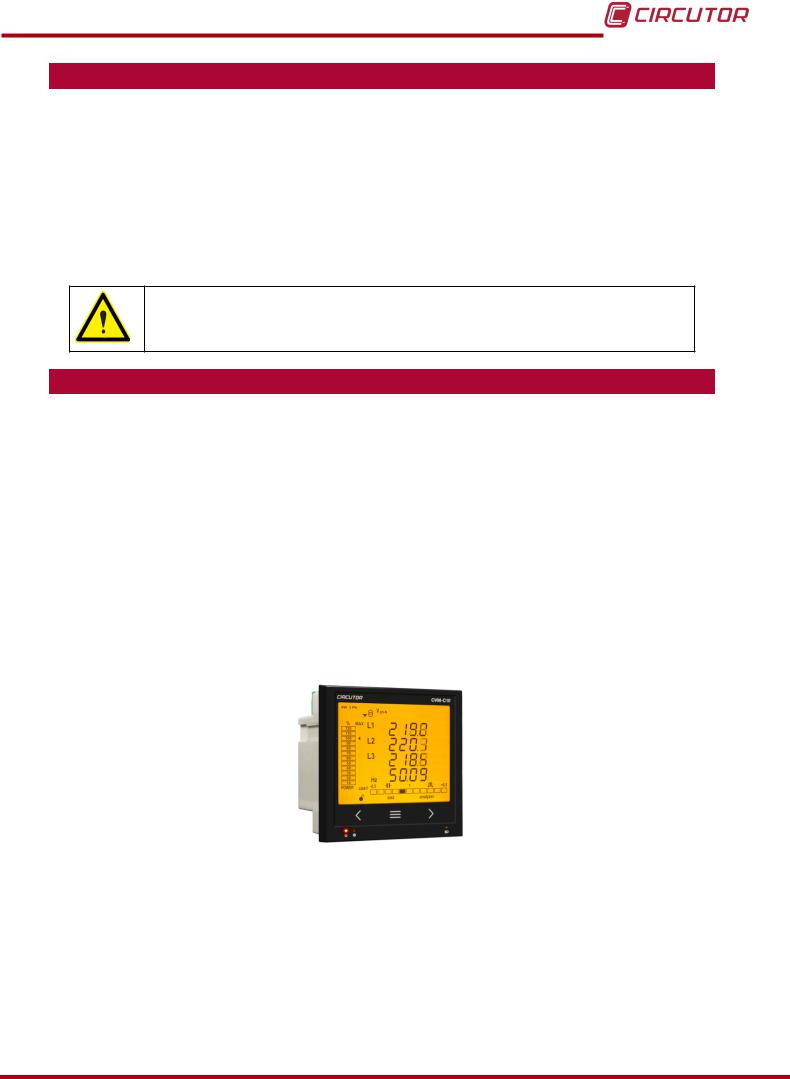
2.- PRODUCT DESCRIPTION
The CVM-C10 unit measures, calculates and displays the main electrical parameters of the following networks: single-phase, two-phase, with and without neutral, balanced three-phase, with ARON measurements or unbalanced. The measurement will be taken in RMS with the three AC voltage inputs and three current inputs.
There are 3 versions of the unit, depending on the type of current input:
CVM-C10-ITF, indirect current measurement with /5A or /1A transformers.
CVM-C10-ITF-IN, indirect current measurement with /5A or /1A transformers and an input to measure the neutral current.
CVM-C10-MC, indirect current measurement with efficient transformers of the
MC1 and MC3 series.
CVM-C10-mV indirect current measurement with /0.333V transformers.
The unit features:
-3 keys that allow you to browse between the various screens and program the unit.
-3 indicator LEDs: CPU, ALARM and KEY.
-LCD display, displays all parameters,
-2 digital inputs, used to select the tariff or detect the logic state of external signals.
-2 digital outputs, fully programmable.
(Not available in the CVM-C10-ITF-IN model)
-2 alarm relays, fully programmable.
-RS-485 Communications, with two serial protocols: MODBUS RTU© and BACnet.
Instruction Manual |
7 |
CVM-C10
3.- UNIT INSTALLATION
3.1.- PRIOR RECOMMENDATIONS
In order to use the unit safely, it is critical that individuals who handle it follow the safety measures set out in the standards of the country where it is being used, use the necessary personal protective equipment, and pay attention to the various warnings indicated in this instruction manual.
The CVM-C10 unit must be installed by authorised and qualified staff.
The power supply plug must be disconnected and measuring systems switched off before handling, altering the connections or replacing the unit. It is dangerous to handle the unit while it is powered.
Also, it is critical to keep the cables in perfect condition in order to avoid accidents, personal injury and damage to installations.
The manufacturer of the unit is not responsible for any damage resulting from failure by the user or installer to heed the warnings and/or recommendations set out in this manual, nor for damage resulting from the use of non-original products or accessories or those made by other manufacturers.
If an anomaly or malfunction is detected in the unit, do not use it to take any measurements.
Inspect the work area before taking any measurements. Do not take measurements in dangerous areas or where there is a risk of explosion.
Disconnect the unit from the power supply (unit and measuring system power supply) before maintaining, repairing or handling the unit's connections.
Please contact the after-sales service if you suspect that there is an operational fault in the unit.
8 |
Instruction Manual |

CVM-C10
3.2.- INSTALLATION
The unit will be installed on a panel (92+0.8 x 92+0.8 mm panel drill hole, in compliance with DIN
43700). All connections are located inside the electric panel.
Terminals, opening covers or removing elements can expose parts that are hazardous to the touch while the unit is powered. Do not use the unit until it is fully installed.
The unit must be connected to a power circuit that is protected with gl (IEC 269) or M type fuses with a rating of 0.5 to 2A. It must be fitted with a circuit breaker or equivalent device, in order to be able to disconnect the unit from the power supply network.
The power and voltage measuring circuit must be connected with cables that have a minimum cross-section of 1mm2.
The secondary line of the current transformer will have a minimum cross-section of 2.5 mm2.
Instruction Manual |
9 |

CVM-C10
3.3.- UNIT TERMINALS
3.3.1.- List of terminals, CVM-C10-ITF, CVM-C10-MC and CVM-C10-mV models
Table 2:List of terminals of the CVM-C10-ITF, CVM-C10-MC and CVM-C10-mV.
|
Unit terminals |
|
1 : A1 Auxiliary power supply. |
|
13: I2, digital input 2 / tariff selection |
2: A2 Auxiliary power supply. |
|
14: VL1, Voltage input L1 |
3: Rc, Common relay output |
|
15: VL2, Voltage input L2 |
4: R2, Relay output 2 |
|
16: VL3,Voltage input L3 |
5: R1, Relay output 1 |
|
17: N, Neutral |
|
|
|
6: CT, Common digital output. |
|
18: S1 , Current input L1 |
7: T2, Digital output 2 |
|
19: S2, Current input L1 |
|
|
|
8: T1, Digital output 1 |
|
20: S1, Current input L2 |
|
|
|
9: A(+), RS485 |
|
21: S2, Current input L2 |
|
|
|
10: B(-), RS485 |
|
22: S1, Current input L3 |
|
|
|
11: GND, for RS485 and digital inputs |
|
23: S2, Current input L3 |
|
|
|
12: I1, digital input 1 / tariff selection |
|
|
|
|
|
|
|
|
2 |
3 |
4 |
5 |
|
6 |
|
7 |
|
|
8 |
9 |
|
10 |
11 |
12 |
|
1 |
|
|
|
|
|
|
|
|
|
|
|
|
|
|
|
13 |
|
|
|
|
|
OUTPUTS |
|
S0+ |
|
|
|
|
|
|
|
|
|
|
|
|
|
|
|
S0S0+ |
|
RS485 |
INPUTS |
|
|
|
||||
|
|
|
|
|
|
|
|
|
|
|
|
|
||||
|
|
POWER SUPPLY |
Rc R2 R1 |
Tc T2 |
T1 |
A(+) B(-) |
|
I1 |
I2 |
|
|
|
||||
|
|
|
|
|
|
|
|
|
|
GND |
|
|
|
|
|
|
|
|
Ph-Ph |
|
Ph-N |
|
|
|
|
|
|
|
|
|
|
||
|
|
520V ~ |
|
300V |
~ |
P1 |
L1 |
P2 P1 |
|
P2 P1 |
P2 |
|
|
|||
|
|
VL1 |
VL2 |
|
VL3 |
N |
|
|
L2 |
|
L3 |
|
|
|
||
|
|
|
S1 |
S2 |
S1 |
S2 |
S1 |
S2 |
|
|
|
|||||
|
14 |
15 |
16 |
17 |
|
|
18 |
19 |
|
20 |
21 |
22 |
23 |
|||
Figure 1:Terminals of the CVM-C10-ITF, CVM-C10-MC and CVM-C10-mV.
10 |
Instruction Manual |
CVM-C10
3.3.2.- List of terminals, CVM-C10-ITF-IN models.
Table 3:List of terminals of the CVM-C10-ITF-IN.
|
Unit terminals |
|
1 : A1 Auxiliary power supply. |
|
13: I2, digital input 2 / tariff selection |
2: A2 Auxiliary power supply. |
|
14: VL1, Voltage input L1 |
3: Rc, Common relay output |
|
15: VL2, Voltage input L2 |
4: R2, Relay output 2 |
|
16: VL3,Voltage input L3 |
5: R1, Relay output 1 |
|
17: N, Neutral |
|
|
|
6: Not connected |
|
18: S1 , Current input L1 |
7: S2, Neutral current input |
|
19: S2, Current input L1 |
|
|
|
8: S1, Neutral current input |
|
20: S1, Current input L2 |
|
|
|
9: A(+), RS485 |
|
21: S2, Current input L2 |
|
|
|
10: B(-), RS485 |
|
22: S1, Current input L3 |
|
|
|
11: GND, for RS485 and digital inputs |
|
23: S2, Current input L3 |
|
|
|
12: I1, digital input 1 / tariff selection |
|
|
|
|
|
|
|
|
2 |
3 |
4 |
5 |
|
6 |
|
7 |
|
|
8 |
9 |
|
10 |
11 |
12 |
|
1 |
|
|
|
|
|
|
|
|
|
|
|
|
|
|
|
13 |
|
|
|
|
|
OUTPUTS |
|
|
|
|
|
|
|
|
|
|
|
|
|
|
|
|
|
|
|
|
|
RS485 |
INPUTS |
|
|
|
||
|
|
POWER SUPPLY |
Rc R2 R1 |
S2 |
S1 |
A(+) B(-) |
|
I1 |
I2 |
|
|
|
||||
|
|
|
|
|
|
|
|
|
|
|
|
|
|
|||
|
|
|
|
|
|
|
LN |
|
|
GND |
|
|
|
|
|
|
|
|
|
|
|
|
P2 |
|
P1 |
|
|
|
|
|
|||
|
|
|
|
|
|
|
|
|
|
|
|
|
|
|||
|
|
Ph-Ph |
|
Ph-N |
|
|
|
|
|
|
|
|
|
|
||
|
|
520V ~ |
|
300V |
~ |
P1 |
L1 |
P2 P1 |
|
P2 P1 |
P2 |
|
|
|||
|
|
VL1 |
VL2 |
|
VL3 |
N |
|
L2 |
|
L3 |
|
|
|
|||
|
|
|
S1 |
S2 |
S1 |
S2 |
S1 |
S2 |
|
|
|
|||||
|
14 |
15 |
16 |
17 |
|
18 |
|
19 |
|
20 |
21 |
22 |
23 |
|||
Figure 2:Terminals of the CVM-C10-ITF-IN.
Instruction Manual |
11 |
CVM-C10
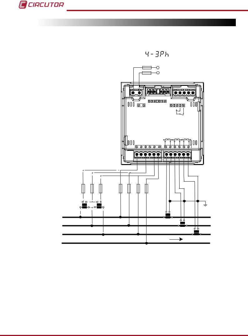
3.4.- CONNECTION DIAGRAM
3.4.1.- Measuring Three-Phase Networks with a 4-wire connection, CVM-C10-ITF and CVM-C10-mV model.
|
|
|
Measurement system: |
|
|
|
|
|
|
|
|
|
|
|||
|
|
|
|
|
|
|
|
|
|
|
Power |
|
|
|
|
|
|
|
|
|
|
|
|
|
|
|
Supply |
|
|
|
|||
|
|
|
|
|
|
|
OUTPUTS |
|
S0+ |
|
|
|
|
|
|
|
|
|
|
|
|
|
|
|
S0S0+ |
|
RS485 |
INPUTS |
|
|
|||
|
|
|
|
|
|
|
|
|
|
|
|
|
|
|||
|
|
|
|
|
POWER SUPPLY |
Rc R2 R1 |
Tc T2 |
T1 |
A(+) B(-) |
|
I1 I2 |
|
|
|||
|
|
|
|
|
|
|
|
|
|
|
|
GND |
|
|
|
|
|
|
|
|
|
Ph-Ph |
Ph-N |
|
|
|
|
|
|
|
|
||
|
|
|
|
|
520V ~ |
300V |
~ |
P1 |
L1 |
P2 P1 |
L2 |
P2 P1 |
P2 |
|
||
|
|
|
|
|
VL1 |
VL2 |
VL3 |
N |
|
|
|
|
L3 |
|
||
|
|
|
|
|
S1 |
S2 |
S1 |
S2 |
S1 |
S2 |
|
|||||
VL1 |
VL2 |
VL3 |
|
|
|
|
|
|
|
|
|
|
|
|
|
|
|
|
|
VL1 |
VL2 |
VL3 |
N |
|
|
|
|
|
|
|
|
|
|
a |
b |
|
a |
|
|
|
|
|
|
|
|
|
|
|
|
|
|
|
b |
|
|
|
|
|
|
|
|
|
|
|
|
|
|
A |
B |
A |
B |
|
|
|
|
|
|
|
|
|
|
|
|
|
L1 |
|
|
|
|
|
|
|
|
S1 |
|
S2 |
|
|
|
|
|
|
|
|
|
|
|
|
|
P1 |
|
|
P2 |
|
|
|
|
|
|
|
|
|
|
|
|
|
|
|
|
S1 |
|
S2 |
|
||
L2 |
|
|
|
|
|
|
|
|
|
|
|
|
P1 |
|
P2 S1 |
|
|
|
|
|
|
|
|
|
|
|
|
|
|
|
S2 |
||
L3 |
|
|
|
|
|
|
|
|
|
|
|
|
|
|
P1 |
P2 |
|
|
|
|
|
|
|
|
LOAD |
|
|
|
|||||
|
|
|
|
|
|
|
|
|
|
|
|
|
||||
N
Figure 3: Three-Phase measuring with a 4-wire connection, CVM-C10-ITF and CVM-C10-mV model.
12 |
Instruction Manual |
CVM-C10
3.4.2.- Measuring Three-Phase Networks with a 4-wire connection, CVM-C10-ITF-IN model.
Measurement system:
Power
 Supply
|
|
|
|
|
|
|
OUTPUTS |
|
|
|
|
|
|
|
|
|
|
|
|
|
|
|
|
|
|
|
|
|
|
|
RS485 |
INPUTS |
|
|
|
|
|
|
|
|
|
|
POWER SUPPLY |
Rc R2 R1 |
S2 LN |
S1 |
A(+) B(-) |
|
I1 I2 |
|
|
|
|
|||
|
|
|
|
|
|
|
|
|
GND |
|
|
|
|
|
||||
|
|
|
|
|
|
|
|
P2 |
|
P1 |
|
|
|
|
|
|||
|
|
|
|
|
|
|
|
|
|
|
|
|
|
|
|
|||
|
|
|
|
|
Ph-Ph |
Ph-N |
|
|
|
|
|
|
|
|
|
|
||
|
|
|
|
|
520V ~ |
300V |
~ |
P1 |
L1 |
P2 P1 |
L2 |
P2 P1 |
P2 |
|
|
|
||
|
|
|
|
|
VL1 |
VL2 |
VL3 |
N |
|
|
|
L3 |
|
|
|
|||
|
|
|
|
|
S1 |
S2 |
S1 |
S2 |
S1 |
S2 |
|
|
|
|||||
VL1 |
VL2 |
VL3 |
|
|
|
|
|
|
|
|
|
|
|
|
|
|
|
|
|
|
|
VL1 |
VL2 |
VL3 |
N |
|
|
|
|
|
|
|
|
|
|
|
|
a |
b |
a |
b |
|
|
|
|
|
|
|
|
|
|
|
|
|
|
|
|
|
|
|
|
|
|
|
|
|
|
|
|
|
|
|
|
||
A |
B |
A |
B |
|
|
|
|
|
S1 |
|
|
S2 |
|
|
|
|
|
|
|
|
|
|
|
|
|
|
|
|
|
|
|
|
|
|
|
||
L1 |
|
|
|
|
|
|
|
|
P1 |
|
|
P2 |
|
|
|
|
|
|
|
|
|
|
|
|
|
|
|
|
|
S1 |
|
S2 |
|
|
|
||
|
|
|
|
|
|
|
|
|
|
|
|
|
|
|
|
|
||
L2 |
|
|
|
|
|
|
|
|
|
|
|
P1 |
|
P2 S1 |
|
|
|
|
|
|
|
|
|
|
|
|
|
|
|
|
|
S2 |
|
|
|||
L3 |
|
|
|
|
|
|
|
|
|
|
|
|
|
|
P1 |
P2 |
|
|
|
|
|
|
|
|
|
LOAD |
|
|
|
|
|
S1 |
S2 |
||||
N |
|
|
|
|
|
|
|
|
|
|
|
|
|
|
|
|||
|
|
|
|
|
|
|
|
|
|
|
|
|
|
|
|
P1 |
P2 |
|
|
|
|
|
|
|
|
|
|
|
|
|
|
|
|
|
|
||
Figure 4: Three-Phase Measuring with a 4-wire connection, CVM-C10-ITF-IN model.
Instruction Manual |
13 |
CVM-C10
3.4.3.- Measuring Three-Phase Networks with a 4-wire connection, CVM-C10-MC model.
Measurement system:
|
|
|
|
|
|
|
|
|
|
|
Power |
|
|
|
|
|
|
|
|
|
|
|
|
|
|
|
Supply |
|
|
|
|||
|
|
|
|
|
|
|
OUTPUTS |
|
S0+ |
|
|
|
|
|
|
|
|
|
|
|
|
|
|
|
S0S0+ |
|
RS485 |
INPUTS |
|
||||
|
|
|
|
|
|
|
|
|
|
|
|
|
||||
|
|
|
|
|
POWER SUPPLY |
Rc R2 R1 |
Tc T2 |
T1 |
A(+) B(-) |
|
I1 |
I2 |
|
|||
|
|
|
|
|
|
|
|
|
|
|
|
GND |
|
|
|
|
|
|
|
|
|
Ph-Ph |
Ph-N |
|
|
|
|
|
|
|
|
||
|
|
|
|
|
520V ~ |
300V |
~ |
P1 |
L1 |
P2 P1 |
L2 |
P2 P1 |
P2 |
|||
|
|
|
|
|
VL1 |
VL2 |
VL3 |
N |
|
|
|
|
L3 |
|
||
|
|
|
|
|
S1 |
S2 |
S1 |
S2 |
S1 |
S2 |
|
|||||
VL1 |
VL2 |
VL3 |
|
|
|
|
|
|
Grey/Pink |
|
Green/White |
|
Red/Blue |
Brown/Green |
|
|
|
|
|
VL1 |
VL2 |
VL3 |
N |
|
|
|
|
|
|||||
|
|
|
|
|
|
|
|
|
|
|
|
|
||||
a |
b |
a |
b |
|
|
|
|
|
|
|
|
|
|
|
|
|
|
|
|
|
|
|
|
|
|
|
|
|
|
|
|
||
A |
B |
A |
B |
|
|
|
|
|
|
|
|
|
|
|
|
|
L1 |
|
|
|
|
|
|
|
|
|
|
|
1P1 |
|
1P2 |
|
|
|
|
|
|
|
|
|
|
|
|
|
|
|
|
|||
L2 |
|
|
|
|
|
|
|
|
|
|
|
2P1 |
|
2P2 |
|
|
L3 |
|
|
|
|
|
|
|
|
|
|
|
3P1 |
|
3P2 |
|
|
N |
|
|
LOAD |
|
|
|
|
|
|
|
|
|
|
|
|
|
|
|
|
|
|
|
|
|
|
|
|
|
|
|
|
|
|
Figure 5: Three-Phase measuring with a 4-wire connection, CVM-C10-MC model.
The MC transformer secondary value is set to 0.250 A (fixed value)
14 |
Instruction Manual |
CVM-C10
3.4.4.- Measuring Three-Phase Networks with a 3-wire connection, CVM-C10-ITF and CVM-C10-mV model.
|
|
|
Measurement system: |
|
|
|
|
|
|
|
|
|
|
||||
|
|
|
|
|
|
|
|
|
|
Power |
|
|
|
|
|||
|
|
|
|
|
|
|
|
|
|
Supply |
|
|
|
|
|||
|
|
|
|
|
|
|
|
OUTPUTS |
|
S0+ |
|
|
|
|
|
|
|
|
|
|
|
|
|
|
|
|
S0S0+ |
|
RS485 |
INPUTS |
|
|
|||
|
|
|
|
|
|
|
|
|
|
|
|
|
|
|
|||
|
|
|
|
|
|
POWER SUPPLY |
Rc R2 R1 |
Tc T2 |
T1 |
A(+) B(-) |
|
I1 I2 |
|
|
|||
|
|
|
|
|
|
|
|
|
|
|
|
|
GND |
|
|
|
|
|
|
|
|
|
|
Ph-Ph |
Ph-N |
|
|
|
|
|
|
|
|
||
|
|
|
|
|
|
520V ~ |
300V |
~ |
P1 |
L1 |
P2 P1 |
L2 |
P2 P1 |
P2 |
|
||
|
|
|
|
|
|
VL1 |
VL2 |
VL3 |
N |
|
|
|
|
L3 |
|
||
|
|
|
|
|
|
S1 |
S2 |
S1 |
S2 |
S1 |
S2 |
|
|||||
VL1 |
VL2 |
VL3 |
|
|
|
|
|
|
|
|
|
|
|
|
|
|
|
|
|
|
|
VL1 |
VL2 |
VL3 |
|
|
|
|
|
|
|
|
|
|
|
a |
b |
|
a |
b |
|
|
|
|
|
|
|
|
|
|
|
|
|
|
|
|
|
|
|
|
|
|
|
|
|
|
|
|
|
||
A |
B |
A |
|
B |
|
|
|
|
|
S1 |
|
S2 |
|
|
|
|
|
|
|
|
|
|
|
|
|
|
|
|
|
|
|
|
|||
L1 |
|
|
|
|
|
|
|
|
|
P1 |
|
|
P2 |
|
|
|
|
|
|
|
|
|
|
|
|
|
|
|
|
S1 |
S2 |
|
|||
L2 |
|
|
|
|
|
|
|
|
|
|
|
|
P1 |
|
P2 S1 |
S2 |
|
|
|
|
|
|
|
|
|
LOAD |
|
|
|
|
|||||
L3 |
|
|
|
|
|
|
|
|
|
|
|
|
|
|
|
||
|
|
|
|
|
|
|
|
|
|
|
|
|
|
|
P1 |
P2 |
|
|
|
|
|
|
|
|
|
|
|
|
|
|
|
|
|
||
Figure 6: Three-Phase measuring with a 3-wire connection, CVM-C10-ITF and CVM-C10-mV model.
Instruction Manual |
15 |
CVM-C10
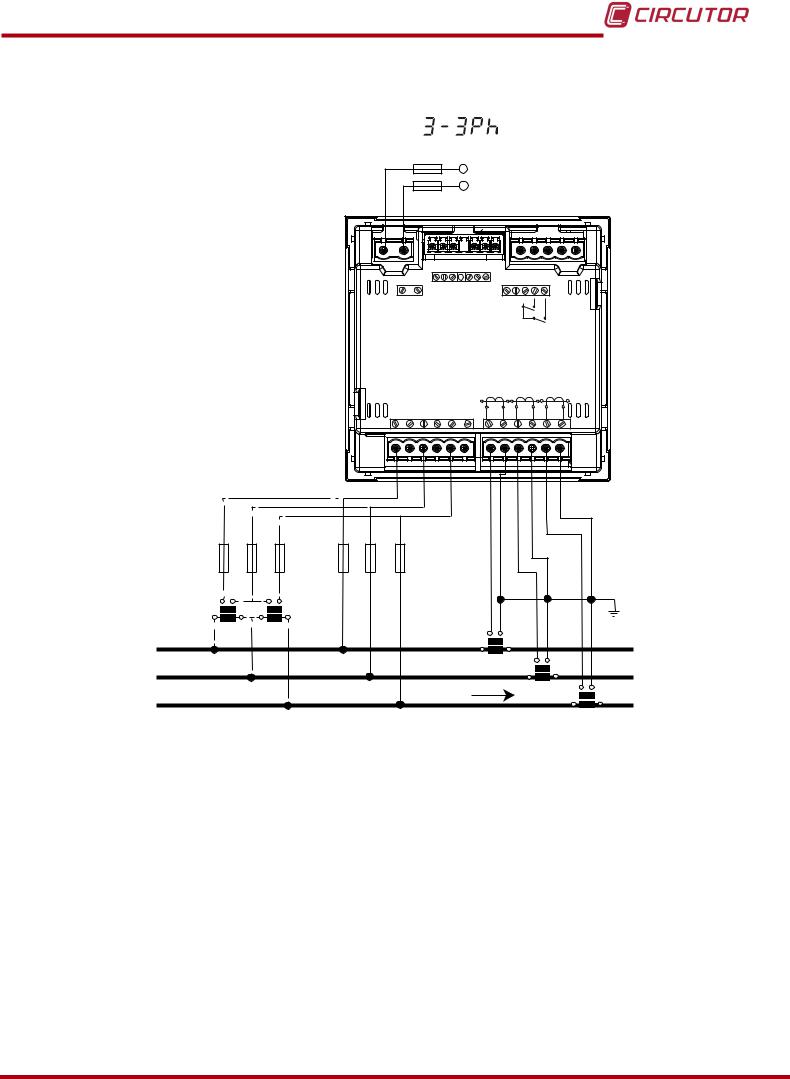
3.4.5.- Measuring Three-Phase Networks with a 3-wire connection, CVM-C10-MC model.
|
|
|
Measurement system: |
|
|
|
|
|
|
|
|
|
|||
|
|
|
|
|
|
|
|
|
|
|
Power |
|
|
|
|
|
|
|
|
|
|
|
|
|
|
Supply |
|
|
|||
|
|
|
|
|
|
|
OUTPUTS |
|
S0+ |
|
|
|
|
|
|
|
|
|
|
|
|
|
|
S0S0+ |
|
RS485 |
INPUTS |
|
|||
|
|
|
|
|
|
|
|
|
|
|
|
|
|||
|
|
|
|
|
POWER SUPPLY |
Rc R2 R1 |
Tc T2 |
T1 |
A(+) B(-) |
|
I1 I2 |
||||
|
|
|
|
|
|
|
|
|
|
|
|
GND |
|
|
|
|
|
|
|
|
Ph-Ph |
Ph-N |
|
|
|
|
|
|
|
||
|
|
|
|
|
520V ~ |
300V |
~ |
P1 |
L1 |
P2 P1 |
L2 |
P2 P1 |
P2 |
||
|
|
|
|
|
VL1 |
VL2 |
VL3 |
N |
|
|
|
|
L3 |
||
|
|
|
|
|
S1 |
S2 |
S1 |
S2 |
S1 |
S2 |
|||||
VL1 |
VL2 |
|
VL1 |
VL2 |
VL3 |
N |
|
|
Grey/Pink |
|
Green/White |
|
Red/Blue |
Brown/Green |
|
VL3 |
|
|
|
|
|
|
|
|
|
|
|
|
|||
a |
b |
|
a |
|
|
|
|
|
|
|
|
|
|
|
|
|
|
b |
|
|
|
|
|
|
|
|
|
|
|
|
|
A |
B |
A |
B |
|
|
|
|
|
|
|
|
|
|
|
|
L1 |
|
|
|
|
|
|
|
|
|
|
|
1P1 |
|
1P2 |
|
L2 |
|
|
|
|
|
|
|
|
|
|
|
2P1 |
|
2P2 |
|
L3 |
|
|
LOAD |
|
|
|
|
|
|
|
|
3P1 |
|
3P2 |
|
|
|
|
|
|
|
|
|
|
|
|
|
||||
Figure 7: Three-Phase measuring with a 3-wire connection, CVM-C10-MC model.
The MC transformer secondary value is set to 0.250 A (fixed value)
16 |
Instruction Manual |
CVM-C10
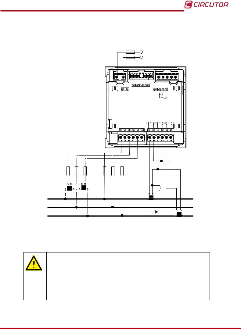
3.4.6.- Measuring Three-Phase Networks with a 3-wire connection and transformers with an ARON connection, CVM-C10-ITF, CVM-C10-MC and CVM-C10-mV models.
Measurement system: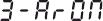
|
|
|
|
|
|
Power |
|
|
|
|
|
|
|
|
|
Supply |
|
|
|||
|
|
OUTPUTS |
|
S0+ |
|
|
|
|
|
|
|
|
|
S0S0+ |
|
RS485 |
INPUTS |
|
|||
|
|
|
|
|
|
|
|
|||
POWER SUPPLY |
Rc R2 R1 |
Tc T2 |
T1 |
A(+) B(-) |
|
I1 I2 |
|
|||
|
|
|
|
|
|
|
GND |
|
|
|
Ph-Ph |
Ph-N |
|
|
|
|
|
|
|
||
520V ~ |
300V |
~ |
P1 |
L1 |
P2 P1 |
L2 |
P2 P1 |
P2 |
||
VL1 |
VL2 |
VL3 |
N |
|
|
|
|
L3 |
||
S1 |
S2 |
S1 |
S2 |
S1 |
S2 |
|||||
VL1 |
VL2 |
VL3 |
|
|
|
|
|
|
|
|
VL1 |
VL2 |
VL3 |
|
|
a |
b |
a |
b |
|
|
|
|
|
|
|
|
|
|
||
A |
B |
A |
B |
|
S1 |
|
|
L1 |
|
|
|
|
S2 |
|
|
|
|
|
|
P1 |
P2 |
|
|
|
|
|
|
|
|
||
L2 |
|
|
|
|
|
S1 |
S2 |
|
|
|
|
|
LOAD |
||
L3 |
|
|
|
|
|
|
|
|
|
|
|
|
P1 |
P2 |
Figure 8: Three-Phase measuring with a 3-wire connection and transformers with an ARON connection, CVM-C10- ITF, CVM-C10-MC and CVM-C10-mV models.
CVM-C10-ITF model:
The transformer secondary value must be 5A or 1A
CVM-C10-MC model:
The MC transformer secondary value is set to 0.250 A (fixed value)
CVM-C10-mV model:
The transformer secondary value must be 0.333 V
Instruction Manual |
17 |
CVM-C10
3.4.7.- Measuring Two-Phase Networks with a 3-wire connection, CVM-C10-ITF, CVM-C10-MC and CVM-C10-mV models.
|
|
Measurement system: |
|
|
|
|
|
|
|
|
|
||
|
|
|
|
|
|
|
|
|
Power |
|
|
|
|
|
|
|
|
|
|
|
|
Supply |
|
|
|||
|
|
|
|
|
OUTPUTS |
|
S0+ |
|
|
|
|
|
|
|
|
|
|
|
|
S0S0+ |
|
RS485 |
INPUTS |
|
|||
|
|
|
|
|
|
|
|
|
|
|
|||
|
|
|
POWER SUPPLY |
Rc R2 R1 |
Tc T2 |
T1 |
A(+) B(-) |
|
I1 I2 |
|
|||
|
|
|
|
|
|
|
|
|
|
GND |
|
|
|
|
|
|
Ph-Ph |
Ph-N |
|
|
|
|
|
|
|
||
|
|
|
520V ~ |
300V |
~ |
P1 |
L1 |
P2 P1 |
L2 |
P2 P1 |
P2 |
||
|
|
|
VL1 |
VL2 |
VL3 |
N |
|
|
|
|
L3 |
||
|
|
|
S1 |
S2 |
S1 |
S2 |
S1 |
S2 |
|||||
VL1 |
N |
VL2 |
|
|
|
|
|
|
|
|
|
|
|
|
|
|
VL1 |
VL2 |
N |
|
|
|
|
|
|
|
|
a |
b |
a |
b |
|
|
|
|
|
|
|
|
|
|
|
|
|
|
|
|
|
|
|
|
|
|
|
|
A |
B |
A |
B |
|
|
|
S1 |
|
S2 |
|
|
|
|
|
|
|
|
|
|
|
|
|
|
|
|||
L1 |
|
|
|
|
|
|
P1 |
|
|
P2 |
|
|
|
|
|
|
|
|
|
|
|
|
S1 |
S2 |
|||
|
|
|
|
|
|
|
|
|
|
|
|||
L2 |
|
|
|
|
|
|
|
|
|
P1 |
|
P2 |
|
|
|
|
|
|
|
|
|
|
|
|
|||
N |
|
|
|
|
|
|
|
|
|
|
|
LOAD |
|
|
|
|
|
|
|
|
|
|
|
|
|
|
|
Figure 9: Measuring Two-Phase Networks with a 3-wire connection, CVM-C10-ITF, CVM-C10-MC and CVM-C10-mV models.
CVM-C10-ITF model:
The transformer secondary value must be 5A or 1A
CVM-C10-MC model:
The MC transformer secondary value is set to 0.250 A (fixed value)
CVM-C10-mV model:
The transformer secondary value must be 0.333 V
18 |
Instruction Manual |
CVM-C10
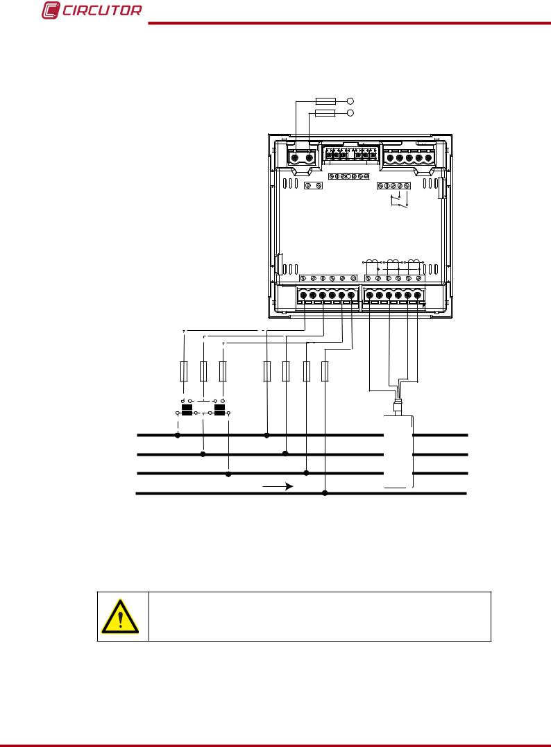
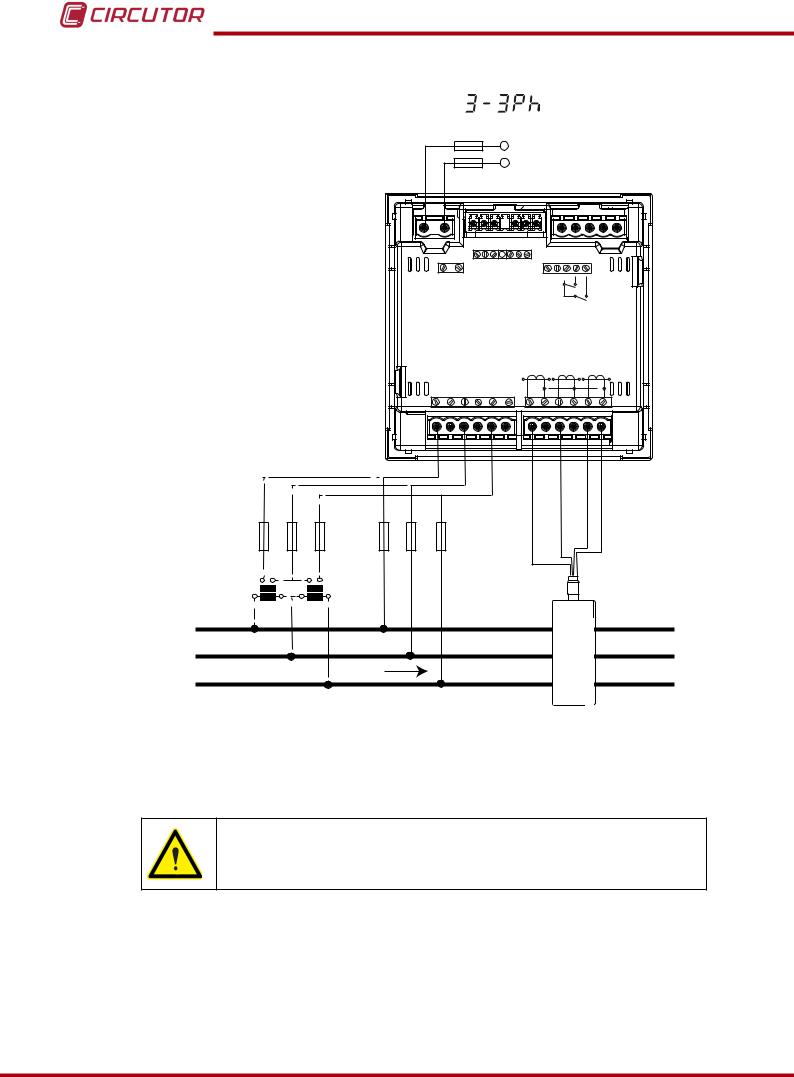
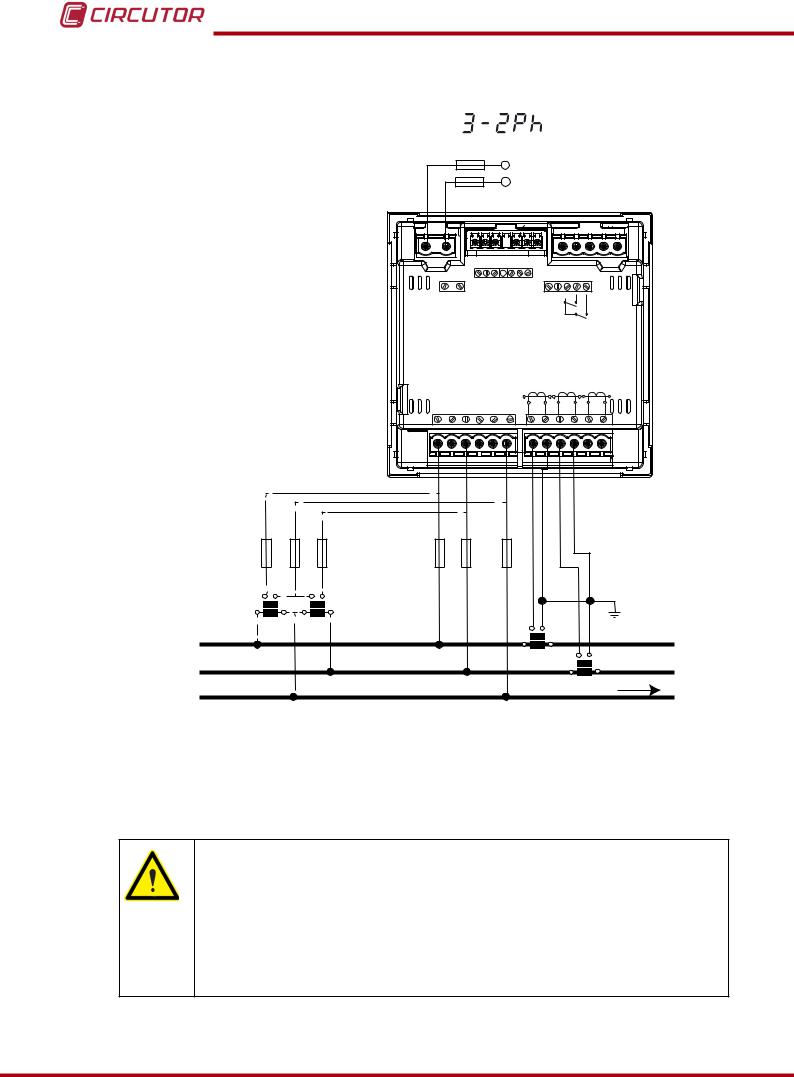
3.4.8.- Measuring Two-Phase Networks with a 3-wire connection, CVM-C10-ITF-IN model.
|
|
|
Measurement system: |
|
|
|
|
|
|
|
|
|
|
||
|
|
|
|
|
|
|
Power |
|
|
|
|
|
|||
|
|
|
|
|
|
|
Supply |
|
|
|
|
|
|||
|
|
|
|
|
OUTPUTS |
|
|
|
|
|
|
|
|
|
|
|
|
|
|
|
|
|
|
|
|
RS485 |
INPUTS |
|
|
|
|
|
|
|
POWER SUPPLY |
Rc R2 R1 |
S2 LN |
S1 |
A(+) B(-) |
|
I1 I2 |
|
|
|
|||
|
|
|
|
|
|
|
GND |
|
|
|
|
||||
|
|
|
|
|
|
P2 |
|
P1 |
|
|
|
|
|||
|
|
|
|
|
|
|
|
|
|
|
|
|
|||
|
|
|
Ph-Ph |
Ph-N |
|
|
|
|
|
|
|
|
|
||
|
|
|
520V ~ |
300V |
~ |
P1 |
L1 |
P2 P1 |
L2 |
P2 P1 |
P2 |
|
|
||
|
|
|
VL1 |
VL2 |
VL3 |
N |
|
|
|
L3 |
|
|
|||
|
|
|
S1 |
S2 |
S1 |
S2 |
S1 |
S2 |
|
|
|||||
VL1 |
N |
|
VL2 |
|
|
|
|
|
|
|
|
|
|
|
|
|
|
|
VL1 |
VL2 |
N |
|
|
|
|
|
|
|
|
|
|
a |
b |
|
a |
|
|
|
|
|
|
|
|
|
|
|
|
|
|
b |
|
|
|
|
|
|
|
|
|
|
|
|
|
|
|
|
|
|
|
|
|
|
|
|
|
|
|
|
|
A |
B |
A |
B |
|
|
|
S1 |
|
|
|
|
|
|
|
|
|
|
|
|
|
|
|
|
|
S2 |
|
|
|
|
|
|
L1 |
|
|
|
|
|
|
P1 |
|
|
P2 |
|
|
|
|
|
|
|
|
|
|
|
|
|
|
S1 |
S2 |
|
|
|||
L2 |
|
|
|
|
|
|
|
|
|
|
P1 |
|
P2 |
|
|
|
|
|
|
|
|
|
|
LOAD |
|
S1 |
S2 |
||||
N |
|
|
|
|
|
|
|
|
|
|
|
|
|||
|
|
|
|
|
|
|
|
|
|
|
|
|
P1 |
P2 |
|
|
|
|
|
|
|
|
|
|
|
|
|
|
|
||
Figure 10: Measuring Two-Phase Networks with a 3-wire connection, CVM-C10-ITF-IN model.
Instruction Manual |
19 |
CVM-C10
3.4.9.- Measuring Single-Phase Networks, phase to phase, with a 2-wire connection, CVM-C10-ITF, CVM-C10-MC and CVM-C10-mV models.
Measurement system: |
|
|
|
|
|
|
|
|
|
||
|
|
|
|
|
|
|
Power |
|
|
|
|
|
|
|
|
|
|
Supply |
|
|
|||
|
|
|
OUTPUTS |
|
S0+ |
|
|
|
|
|
|
|
|
|
|
S0S0+ |
|
RS485 |
INPUTS |
|
|||
|
|
|
|
|
|
|
|
|
|||
|
POWER SUPPLY |
Rc R2 R1 |
Tc T2 |
T1 |
A(+) B(-) |
|
I1 I2 |
|
|||
|
|
|
|
|
|
|
|
GND |
|
|
|
|
Ph-Ph |
Ph-N |
|
|
|
|
|
|
|
||
|
520V ~ |
300V |
~ |
P1 |
L1 |
P2 P1 |
L2 |
P2 P1 |
P2 |
||
|
VL1 |
VL2 |
VL3 |
N |
|
|
|
|
L3 |
||
|
S1 |
S2 |
S1 |
S2 |
S1 |
S2 |
|||||
VL1 |
VL2 |
|
|
|
|
|
|
|
|
|
|
|
VL1 |
VL2 |
|
|
|
|
|
|
|
|
|
a |
b |
|
|
|
|
|
|
|
|
|
|
A |
B |
|
|
|
|
|
|
|
|
|
|
|
|
|
|
|
S1 |
|
S2 |
|
|
|
|
L1 |
|
|
|
|
P1 |
|
|
P2 |
|
|
|
L2 |
|
|
|
|
|
|
LOAD |
||||
|
|
|
|
|
|
|
|
|
|
|
|
Figure 11: Measuring Single-Phase Networks, phase to phase, with a 2-wire connection, CVM-C10-ITF, CVM-C10-MC and CVM-C10-mV models.
CVM-C10-ITF model:
The transformer secondary value must be 5A or 1A
CVM-C10-MC model:
The MC transformer secondary value is set to 0.250 A (fixed value)
CVM-C10-mV model:
The transformer secondary value must be 0.333 V
20 |
Instruction Manual |
CVM-C10
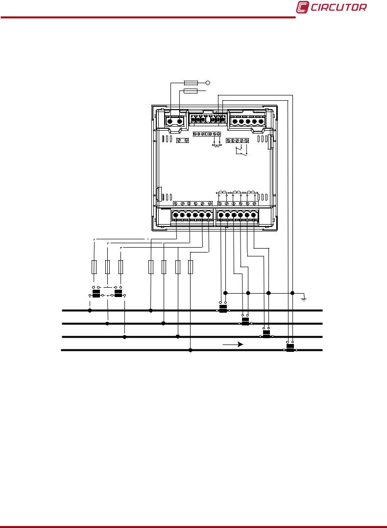
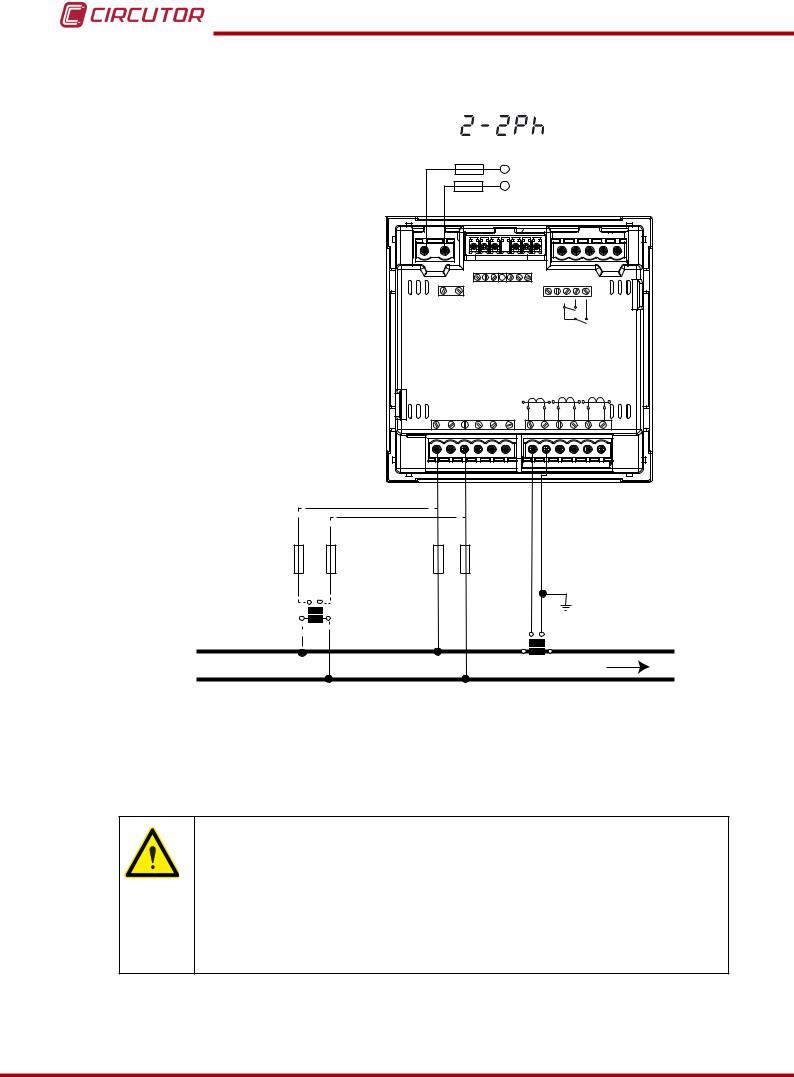
3.4.10.- Measuring Single-Phase Networks, phase to neutral, with a 2-wire connection, CVM-C10-ITF, CVM-C10-MC and CVM-C10-mV models.
Measurement system: |
|
|
|
|
|
|
|
|
|
||
|
|
|
|
|
|
|
Power |
|
|
|
|
|
|
|
|
|
|
Supply |
|
|
|||
|
|
|
OUTPUTS |
|
S0+ |
|
|
|
|
|
|
|
|
|
|
S0S0+ |
|
RS485 |
INPUTS |
|
|||
|
|
|
|
|
|
|
|
|
|||
|
POWER SUPPLY |
Rc R2 R1 |
Tc T2 |
T1 |
A(+) B(-) |
|
I1 I2 |
||||
|
|
|
|
|
|
|
|
GND |
|
|
|
|
Ph-Ph |
Ph-N |
|
|
|
|
|
|
|
||
|
520V ~ |
300V |
~ |
P1 |
L1 |
P2 P1 |
L2 |
P2 P1 |
P2 |
||
|
VL1 |
VL2 |
VL3 |
N |
|
|
|
|
L3 |
||
|
S1 |
S2 |
S1 |
S2 |
S1 |
S2 |
|||||
VL1 |
N |
|
|
|
|
|
|
|
|
|
|
|
VL1 |
|
N |
|
|
|
|
|
|
|
|
a |
b |
|
|
|
|
|
|
|
|
|
|
A |
B |
|
|
|
S1 |
|
|
|
|
|
|
|
|
|
|
|
|
S2 |
|
|
|
||
|
|
|
|
|
|
|
|
|
|
|
|
L1 |
|
|
|
|
P1 |
|
|
P2 |
|
|
|
|
|
|
|
|
|
|
|
|
LOAD |
||
|
|
|
|
|
|
|
|
|
|
|
|
N
Figure 12: Measuring Single-Phase Networks, phase to neutral, with a 2-wire connection, CVM-C10-ITF, CVM-C10-MC and CVM-C10-mV models.
CVM-C10-ITF model:
The transformer secondary value must be 5A or 1A
CVM-C10-MC model:
The MC transformer secondary value is set to 0.250 A (fixed value)
CVM-C10-mV model:
The transformer secondary value must be 0.333 V
Instruction Manual |
21 |
CVM-C10
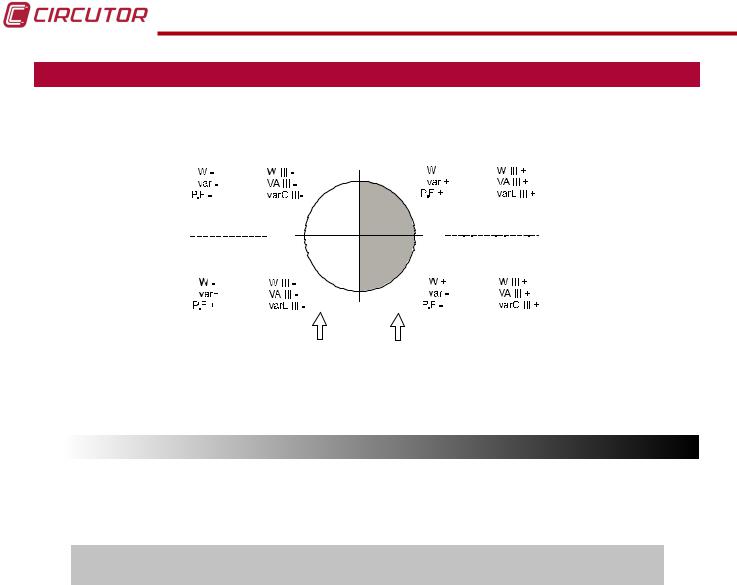
4.- OPERATION
The CVM-C10 is a four-quadrant power analyzer (consumption and generation).
Single-phase |
Three-phase |
90º |
Single-phase |
Three-phase |
|
k |
k |
k |
k |
||
|
|||||
k |
k |
|
k |
k |
|
|
k |
|
|
k |
|
Capacitive |
|
Inductive |
|||
Inductive |
180º |
|
0º |
|
|
|
|
Capacitive |
|||
Single-phase Three-phase |
|
Single-phase Three-phase |
|||
k |
k |
|
k |
k |
|
k |
k |
|
k |
k |
|
|
k |
-90º |
|
k |
|
|
|
|
|
||
Generation Consumption
Power Power
Figure 13: Four quadrants of CVM-C10
4.1.- MEASURING PARAMETERS
The unit displays the electrical parameters shown in Table 4.
Table 4: Measuring parameters of the CVM-C10.
|
Parameter |
Units |
Phases |
Total |
N |
|
|
L1-L2-L3 |
III |
|
|||
|
|
|
|
|
||
|
Phase-neutral voltage |
Vph-N |
|
|
|
|
|
Phase-phase voltage |
Vph-ph |
|
|
|
|
|
Current |
A |
|
|
|
|
|
Frequency |
Hz |
|
|
|
|
|
Active power |
M/kW |
|
|
|
|
|
Apparent power |
M/kVA |
|
|
|
|
|
Total Reactive Power |
M/kvar |
|
|
|
|
|
Total Reactive Power - Consumption |
M/kvar |
|
|
|
|
|
Total Reactive Power - Generation |
M/kvar |
|
|
|
|
|
Total Inductive Reactive Power |
M/kvarL |
|
|
|
|
|
Inductive Reactive Power - Consumption |
M/kvarL |
|
|
|
|
|
Inductive Reactive Power - Generation |
M/kvarL |
|
|
|
|
|
Total Capacitive Reactive Power |
M/kvarC |
|
|
|
|
|
Capacitive Reactive Power - Consumption |
M/kvarC |
|
|
|
|
|
Capacitive Reactive Power - Generation |
M/kvarC |
|
|
|
|
|
Power factor |
PF |
|
|
|
|
|
Cos φ |
φ |
|
|
|
|
|
THD % Voltage |
% THD V |
|
|
|
|
|
THD % Current |
% THD A |
|
|
|
|
|
Harmonic Breakdown - Voltage |
harm V |
|
|
|
|
|
(up to the 31st order harmonic) |
|
|
|
||
|
|
|
|
|
|
|
|
|
|
|
|
||
|
|
|
|
|
||
22 |
|
|
|
Instruction Manual |
||

CVM-C10
Table 4 ( Continuation ) : Measuring parameters of the CVM-C10.
Parameter |
Units |
Phases |
Total |
N |
|
L1-L2-L3 |
III |
||||
|
|
|
|||
Harmonic Breakdown - Current |
harm V |
|
|
|
|
(up to the 31st order harmonic) |
|
|
|||
|
|
|
|
||
Total Active Energy |
M/kWh |
|
|
|
|
Total Inductive Reactive Energy |
M/kvarLh |
|
|
|
|
Total Capacitive Reactive Energy |
M/kvarCh |
|
|
|
|
Total Apparent Energy |
M/kVAh |
|
|
|
|
Active Energy Tariff 1 |
M/kWh |
|
|
|
|
Inductive Reactive Energy Tariff 1 |
M/kvarLh |
|
|
|
|
Capacitive Reactive Energy Tariff 1 |
M/kvarCh |
|
|
|
|
Apparent Energy Tariff 1 |
M/kVAh |
|
|
|
|
Active Energy Tariff 2 |
M/kWh |
|
|
|
|
Inductive Reactive Energy Tariff 2 |
M/kvarLh |
|
|
|
|
Capacitive Reactive Energy Tariff 2 |
M/kvarCh |
|
|
|
|
Apparent Energy Tariff 2 |
M/kVAh |
|
|
|
|
Active Energy Tariff 3 |
M/kWh |
|
|
|
|
Inductive Reactive Energy Tariff 3 |
M/kvarLh |
|
|
|
|
Capacitive Reactive Energy Tariff 3 |
M/kvarCh |
|
|
|
|
Apparent Energy Tariff 3 |
M/kVAh |
|
|
|
|
Maximum Current Demand |
A |
|
|
|
|
Maximum Demand of Active power |
M/kW |
|
|
|
|
Maximum Demand of Apparent Power |
M/kVA |
|
|
|
|
Parameter |
Units |
Tariff: T1-T2-T3 |
Total |
||
No. of hours |
hours |
|
|
|
|
Cost |
COST |
|
|
|
|
CO2 Emissions |
kgCO2 |
|
|
|
|
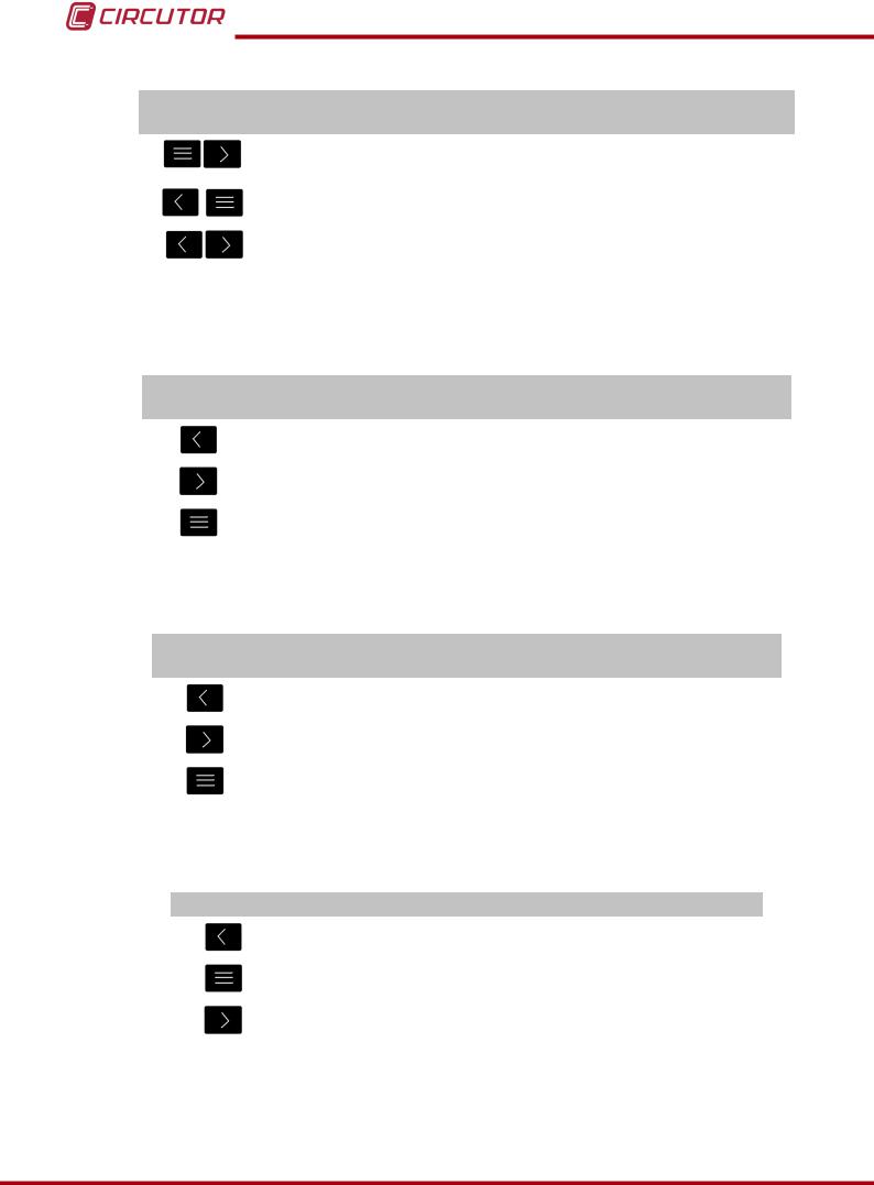
4.2.- KEYBOARD FUNCTIONS
The CVM-C10 has 3 keys that allow you to browse between the various screens and program the unit.
Key functions on measuring screens (Table 5):
Table 5: Key functions on measuring screens.
Key |
Short keystroke |
Long keystroke |
|
(2 s) |
|||
|
|
||
|
Previous screen |
Display of minimum value |
|
|
|
|
|
|
Next screen |
Display of maximum value |
|
|
|
|
|
|
Browsing the different profiles |
Accessing the programming menu |
|
|
(analyzer, user, e3) |
||
|
|
Instruction Manual |
23 |
CVM-C10
Table 5 (Continuation ) : Key functions on measuring screens.
Key |
Short keystroke |
Long keystroke |
|
(2 s) |
|||
|
|
||
|
|
Display of the Maximum Demand |
|
|
|
|
|
|
|
Active alarm information |
|
|
|
|
|
|
|
Unlocks the active alarm |
|
|
|
|
Key functions on harmonics screens (Table 6):
|
Table 6: Key functions on harmonics screens. |
||
Key |
Short keystroke |
Long keystroke |
|
(2 s) |
|||
|
|
||
|
Output of the harmonics screens |
|
|
|
|
|
|
|
Next screen |
|
|
|
|
|
|
|
Browsing the different types of har- |
Accessing the programming |
|
|
monics |
menu |
|
Key functions on the programming menu, query mode (Table 7):
Table 7: Key functions on the programming menu, query mode.
Key |
Short keystroke |
Long keystroke |
|
(2 s) |
|||
|
|
||
|
Previous screen |
Programming output |
|
|
|
|
|
|
Next screen |
Programming output |
|
|
|
|
|
|
|
Opening the programming menu in the edit |
|
|
|
mode |
Key functions on the programming menu, edit mode (Table 8):
|
Table 8: Key functions on the programming menu, edit mode. |
Key |
Keystroke |
|
Next page |
|
|
|
Increases the digits (0-9) or rotates between the different options. |
|
|
|
Moves an editable digit (flashing) |
|
|
24 |
Instruction Manual |
CVM-C10
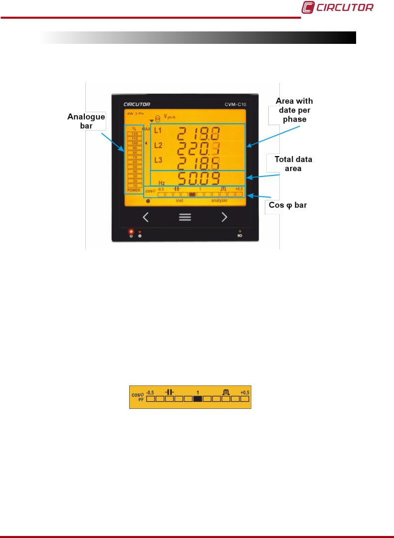
4.3.- DISPLAY
The unit has a backlit LCD display showing all the parameters listed in Table 3.
The display is divided into four areas (Figure 14):
Figure 14: CVM-C10 Display areas
The area with data per phase displays the instantaneous, maximum and minimum values of each phase being measured or calculated by the unit.
The total data area displays the totals of the values being measured or calculated by the unit.
Analogue bar, displays the % of the current power of the installation.
Cos φ - PF Bar, displays the value of the system's Cos φ or power factor in real time.
4.3.1. COS φ - PF (POWER FACTOR) BAR
Figure 15: Cos φ - PF Bar
This bar displays the value of the installation's cos φ or power factor in real time.
The parameter that will be displayed is selected on the programming menu. ( “4.9.13. Selecting the Cos φ - PF bar on the display”)
Instruction Manual |
25 |
Loading...