


 Loading...
Three-phase power analyzer and power quality
USER's MANUAL
(M98206501-03-15A)
1ZD4
CVMk2
 ADVERTENCIAS / SIMBOLOS
Una conexión incorrecta del equipo puede producir la muerte, lesiones PELIGRO graves y riesgo de incendio. Lea y entienda el manual antes de conectar
el equipo. Observe todas las instrucciones de instalación y operación durante el uso de este instrumento.
La instalación, operación y mantenimiento de este instrumento debe ser efectuado por personal cualificado solamente. El Código Eléctrico Nacional define a una persona cualificada como "una que esté familiarizada con la construcción y operación del equipo y con los riesgos involucrados".
ATENCIÓN Consultar el manual de instrucciones antes de utilizar el equipo.
En el presente manual, si las instrucciones precedidas por este símbolo no se respetan o realizan correctamente, pueden ocasionar daños personales o dañar el equipo y /o las instalaciones.
 WARNINGS / SYMBOLS
Death, serious injury, or fire hazard could result from improper connection
DANGER of this instrument. Read and understand this manual before connecting this instrument. Follow all installation and operating instructions while using this instrument.
Installation, operation, and maintenance of this instrument must be performed by qualified personnel only. The National Electrical Code defines a qualified person as “one who has the skills and knowledge related to the construction and operation of the electrical equipment and installations, and who has received safety training on the hazards involved.”
ATTENTION Consult the instruction manual before using the equipment.
In this manual, if the instructions preceded by this symbol are not met or done correctly, can cause personal injury or equipment damage and / or facilities.
2
CVMk2
 AVERTISSEMENT / SYMBOLES
DANGER |
Un branchement incorrect de l’appareil peut entraîner la mort ou des lésions |
|
graves et peut provoquer un incendie. Avant de brancher votre appareil, |
|
lisez attentivement le manuel et assurez-vous de bien avoir compris toutes |
|
les explications données. Respectez toutes les instructions concernant le |
|
mode d’installation de l’appareil et son fonctionnement. |
|
L’installation, le fonctionnement et la maintenance de cet appareil doivent |
|
être réalisés uniquement par du personnel qualifié. Le code électrique |
|
national définit en tant que personne qualifiée "toute personne connaissant |
|
le montage et le fonctionnement de l’appareil ainsi que les risques que |
|
ceux-ci comportent ". |
|
|
ATTENTION Consulter le manuel d’instructions avant d’utiliser l’appareil
Si les instructions suivantes, précédées dans le manuel d’un symbole, ne sont pas respectées ou sont réalisées incorrectement, elles pourront provoquer des dommages personnels ou abîmer l’appareil et/ou les installations
 AVVERTENZE / SIMBOLI
PERICOLO |
Un collegamento errato del dispositivo può provocare morte, lesioni |
|
gravi nonché rischio di incendio. Prima di collegare il dispositivo |
|
leggere attentamente il manuale. Osservare tutte le istruzioni relative |
|
all’installazione e all’operatività durante l’uso di questo strumento. |
|
L’installazione, operatività e manutenzione di questo strumento devono |
|
essere realizzate solamente da personale qualificato. Il Codice Elettrico |
|
Nazionale definisce una persona qualificata come “colui che ha familiarità |
|
con la costruzione e operatività del dispositivo e con i rischi che ne |
|
possano derivare”. |
|
|
ATTENZIONE Consultare il manuale di istruzioni prima di utilizzare il dispositivo
Qualora le istruzioni riportate nel presente manuale precedute da questo simbolo non vengano osservate o realizzate correttamente, possono provocare danni personali o danneggiare il dispositivo e/o gli impianti.
3
|
CVMk2 |
|
WARNHINWEISE / SYMBOLE |
||
|
|
|
GEFAHR |
Durch einen nicht sachgemäßen Anschluss der Anlage können Tod, |
|
|
schwere Verletzungen und Brandrisiko hervorgerufen werden. Bevor Sie |
|
|
die Anlage anschließen, lesen Sie bitte das Handbuch durch und machen |
|
|
Sie sich dessen Inhalt klar. Beachten Sie bei Einsatz dieses Instrumentes |
|
|
sämtliche Installationsund Betriebshinweise. |
|
|
Installation, Betrieb und Wartung dieses Instrumentes müssen |
|
|
ausschließlich von entsprechend qualifiziertem Personal vorgenommen |
|
|
werden. Von dem nationalen Elektrocode wird eine qualifizierte Person als |
|
|
jemand definiert, “der mit der Konstruktion und dem Betrieb einer Anlage |
|
|
und der damit verbundenen Risiken vertraut ist“. |
|
|
|
|
ACHTUNG |
Vor Inbetriebnahme der Anlage ist das Handbuch zu lesen. |
|
Werden die in dem vorliegenden Handbuch mit diesem Symbol versehenen Hinweise nicht beachtet oder falsch verstanden, können
Personenschäden und Schäden an der Anlage und/oder den Installationen verursacht werden.
 ADVERTÊNCIAS / SÍMBOLOS
PERIGO |
Uma ligação incorrecta do equipamento pode provocar a morte, lesões |
|
graves e risco de incêndio. Leia e compreenda o manual antes de ligar |
|
o equipamento. Observe todas as instruções de instalação e operação |
|
durante o uso deste aparelho. |
|
A instalação, operação e manutenção deste aparelho devem ser levadas a |
|
cabo exclusivamente por pessoal qualificado. O Código Eléctrico Nacional |
|
define uma pessoa qualificada como "uma pessoa que se encontre |
|
familiarizada com a construção e operação do equipamento assim como |
|
com os riscos inerentes” |
|
|
ATENÇÃO
4
Consultar o manual de instruções antes de utilizar o equipamento.
No presente manual, se as instruções que precedem este símbolo não forem respeitadas ou realizadas de forma correcta, podem ocorrer ferimentos pessoais ou danos no equipamento e/ou nas instalações.

CVMk2 |
|
INDICE MANUAL |
|
1. INTRODUCTION |
|
1.1 DESCRIPTION......................................................................................................... |
11 |
1.2 TYPES AVAILABLE................................................................................................. |
12 |
1.3 EXPANSION CARDS .............................................................................................. |
13 |
1.4 CODING FOR OTHER PARAMETERS................................................................... |
13 |
1.5 ANALYSIS PARAMETERS...................................................................................... |
14 |
1.6 ACCESORIES.......................................................................................................... |
14 |
2. INSTALLATION |
|
2.1 ITEMS TO VERIFY UPON RECEPTION................................................................. |
15 |
2.2 ASSEMBLY SITE..................................................................................................... |
15 |
ENVIRONMENTAL CONDITIONS............................................................................. |
15 |
CONSIDERATIONS.................................................................................................... |
15 |
2.3 INSTALLATION METHODS..................................................................................... |
16 |
2.3.1 PROCEDURE.................................................................................................... |
16 |
2.4 SYSTEM CONNECTION.......................................................................................... |
18 |
2.4.1 AUXILIARY POWER SUPPLY.......................................................................... |
18 |
2.4.2 RATED VOLTAGE IN VOLTAGE MEASURING CIRCUIT................................ |
18 |
2.4.3 RATED CURRENT IN CURRENT MEASURING CIRCUIT.............................. |
18 |
2.4.4 WORKING CONDITIONS................................................................................. |
18 |
2.4.5 SAFETY............................................................................................................. |
19 |
2.4.6 TECHNICAL FEATURES.................................................................................. |
19 |
2.5 TERMINALS DESCRIPTION................................................................................... |
20 |
2.5.1 TAG FOR VOLTAGE AND CT CONNECTIONS............................................... |
20 |
2.5.2 POWER SUPPLY AND COMMUNICATIONS TAG........................................... |
20 |
2.6 MEASURING INPUT CONNECTION DIAGRAMS.................................................. |
21 |
2.6.1 - 4 CT AND 5 VOLTAGE REFERENCES.......................................................... |
21 |
2.6.2 - 4 CT AND 4 VOLTAGE REFERENCES.......................................................... |
21 |
2.6.3 - 3 CT AND 4 VOLTAGE REFERENCES.......................................................... |
22 |
2.6.4 - 3 CT AND 3 VOLTAGE REFERENCES.......................................................... |
22 |
2.6.5 - 4 CT AND 2 VOLTAGE TRANSFORMERS.................................................... |
23 |
2.6.6 - 3 CT AND 2 VOLTAGE TRANSFORMERS.................................................... |
23 |
5

|
CVMk2 |
2.6.7 - 2 CT AND 2 VOLTAGE TRANSFORMERS.................................................... |
24 |
2.7 POWER SUPPLY CONNECTION DIAGRAM.......................................................... |
24 |
3. OPERATION |
|
3.1 DESCRIPTION OF DEVICE..................................................................................... |
25 |
3.1.1 FRONTAL VIEW................................................................................................ |
25 |
3.1.1.a. Display...................................................................................................... |
26 |
3.1.1.b. Function buttons........................................................................................ |
26 |
3.1.1.c. Navigation buttons..................................................................................... |
26 |
3.1.1.d. SET button.................................................................................................. |
26 |
3.1.1.e. Upper and lower menus............................................................................ |
26 |
3.1.1.f. Module name............................................................................................. |
27 |
3.1.1.e. Icons.......................................................................................................... |
27 |
3.2. START-UP............................................................................................................... |
28 |
4. CONFIGURATION |
|
4.1 MEASURING............................................................................................................ |
29 |
4.2. QUALITY................................................................................................................. |
30 |
4.2.1. QUALITY.......................................................................................................... |
31 |
4.2.2. EVENTS........................................................................................................... |
32 |
4.3. DEMAND................................................................................................................ |
34 |
4.4 TARIFFS................................................................................................................... |
35 |
4.5 DELETE.................................................................................................................... |
36 |
4.6 COMMUNICATIONS................................................................................................ |
37 |
4.7 EXPANSION CARDS............................................................................................... |
38 |
4.7.0. INSERTING EXPANSION CARDS.................................................................. |
38 |
4.7.1. 8 DIGITAL INPUTS AND 8 DIGITAL OUTPUTS.............................................. |
40 |
4.7.1.1. Alarm configuration.................................................................................. |
41 |
4.7.1.2. Digital outputs configuration..................................................................... |
43 |
4.7.1.3. Digital inputs configuration....................................................................... |
44 |
4.7.1.4. Expansion card parameters...................................................................... |
46 |
4.7.1.5. Features.................................................................................................... |
46 |
4.7.2 - 8 DIGITAL INPUTS AND 4 RELAY OUTPUTS .............................................. |
47 |
4.7.2.1. Alarm configuration.................................................................................. |
48 |
6

CVMk2 |
|
4.7.2.2. Relay outputs configuration..................................................................... |
50 |
4.7.2.3. Digital inputs configuration........................................................................ |
51 |
4.7.2.4. Card Connections..................................................................................... |
52 |
4.7.2.5. Expansion card parameters...................................................................... |
53 |
4.7.2.6. Features.................................................................................................... |
53 |
4.7.3 - 8 ANALOGUE INPUTS AND 4 ANALOGUE OUTPUTS ............................... |
54 |
4.7.3.1. Analogue outputs configuration................................................................ |
55 |
4.7.3.2. Analogue inputs codes............................................................................. |
56 |
4.7.3.3. Analogue inputs configuration.................................................................. |
57 |
4.7.3.4. Expansion card parameters...................................................................... |
59 |
4.7.3.5. Features.................................................................................................... |
59 |
4.7.4 - ETHERNET AND μSD MEMORY................................................................... |
60 |
4.7.4.1. Network and communications Protocol..................................................... |
61 |
4.7.4.2. IP Address Configuration......................................................................... |
61 |
4.7.4.3. μSD card configuration............................................................................ |
63 |
4.7.4.4. μSD Card parameters............................................................................... |
63 |
4.7.4.5. Expansions card icons.............................................................................. |
64 |
4.7.4.6. Ethernet card features............................................................................. |
64 |
4.7.5 - μSD MEMORY................................................................................................ |
65 |
4.7.5.1. μSD Card configuration............................................................................. |
65 |
4.7.5.2. μSD card parameters................................................................................ |
66 |
4.7.5.3. Expansion card icons................................................................................ |
67 |
4.7.5.4. Ethernet output features.......................................................................... |
67 |
4.7.6 - 4 ± 5 MAANALOGUE AND STATIC OUTPUTS............................................. |
68 |
4.7.6.1. ± 5 mA analog outputs card configuration................................................ |
68 |
4.7.6.2. ± 5 mA analog outputs configuration........................................................ |
69 |
4.7.6.3. Alarm configuration................................................................................... |
69 |
4.7.6.4. Static outputs configuration....................................................................... |
71 |
4.7.6.5. Outputs wiring........................................................................................... |
71 |
4.7.6.6. Technical Features.................................................................................... |
72 |
4.7.7 - PROFIBUS COMMUNICATIONS CARD........................................................ |
73 |
4.7.7.1. Profibus card configuration....................................................................... |
73 |
7

|
|
|
CVMk2 |
|
4.7.7.2. Card parameters....................................................................................... |
73 |
|
|
4.7.7.3. Slave number configuration...................................................................... |
74 |
|
|
4.7.7.4. Leds information........................................................................................ |
75 |
|
|
4.7.7.5. Profibus connector.................................................................................... |
75 |
|
|
4.7.7.6. GSD Modules............................................................................................ |
76 |
|
|
5. OTHER SYSTEM CONFIGURATIONS |
|
|
|
5.1 PREFERENCES....................................................................................................... |
77 |
|
|
5.1.1 SCREEN............................................................................................................ |
77 |
|
|
5.1.2 CLOCK / TEMPERATURE................................................................................ |
78 |
|
|
5.1.3 SECURITY........................................................................................................ |
79 |
|
|
5.2. TOOLS.................................................................................................................... |
80 |
|
|
5.2.1 DEVICE............................................................................................................. |
80 |
|
|
5.3 MODULES................................................................................................................ |
81 |
|
|
5.3.1 LIST................................................................................................................... |
81 |
|
|
5.3.2 SETUP............................................................................................................... |
83 |
|
|
6. DISPLAY SCREENS |
|
|
|
6.1 MEASURING............................................................................................................ |
84 |
|
|
6.1.1 MAIN.................................................................................................................. |
84 |
|
|
6.1.1.1. System information................................................................................... |
84 |
|
|
6.1.1.2. Maximums................................................................................................. |
87 |
|
|
6.1.1.3. Minimums.................................................................................................. |
88 |
|
|
6.1.2 PHASE-NEUTRAL VOLTAGE .......................................................................... |
89 |
|
|
6.1.2.1. Voltage waveform display......................................................................... |
90 |
|
|
6.1.2.2 Voltage phasors display............................................................................. |
91 |
|
|
6.1.3 PHASE-PHASE VOLTAGE............................................................................... |
92 |
|
|
6.1.4 CURRENT......................................................................................................... |
93 |
|
|
6.1.4.1. Current waveform display......................................................................... |
94 |
|
|
6.1.4.2 Current phasors display............................................................................. |
95 |
|
|
6.1.5 POWERS........................................................................................................... |
96 |
|
|
6.1.5.1 Active power............................................................................................... |
96 |
|
|
6.1.5.2 Inductive Power.......................................................................................... |
96 |
|
8 |
6.1.5.3 Capacitive Power....................................................................................... |
97 |
|
|
|
|
|
|
|
|
|

CVMk2 |
|
6.1.5.4 Apparent Power......................................................................................... |
98 |
6.1.5.5 Total Power................................................................................................ |
99 |
6.1.6, POWER FACTOR.......................................................................................... |
100 |
6.1.7 COS j ......................................................................................................... |
100 |
6.2. DEMAND.............................................................................................................. |
103 |
6.3 ENERGY ............................................................................................................... |
104 |
6.3.1 PRESENT ENERGY....................................................................................... |
104 |
6.3.2 MONTH ENERGY........................................................................................... |
105 |
6.3.3 YEARLY ENERGY.......................................................................................... |
105 |
6.4 EXPANSION CARDS ........................................................................................... |
106 |
6.4.1 CARD WITH 8 DIGITAL INPUTS / 8 OUTPUTS............................................ |
106 |
6.4.2 CARD WITH 8 RELAY INPUTS / 4 OUTPUTS.............................................. |
107 |
6.4.3 CARD WITH 8 ANALOGUE INPUTS / 4 OUTPUTS...................................... |
107 |
6.4.4 μSD-ETHERNET AND μSD MEMORY CARD................................................ |
108 |
6.4.5 μSD MEMORY CARD..................................................................................... |
108 |
6.4.6 ANALOGUE ± 5 MAAND STATIC OUTPUTS CARD..................................... |
109 |
6.4.7 PROFIBUS COMMUNICATIONS CARD........................................................ |
110 |
7. QUALITY |
|
7.1 HARMONICS......................................................................................................... |
111 |
7.1.1 VOLTAGE THD............................................................................................... |
112 |
7.1.2 CURRENT THD.............................................................................................. |
113 |
7.1.3 VOLTAGE HARMONICS................................................................................. |
114 |
7.1.4 CURRENT HARMONICS................................................................................ |
116 |
7.2. DISTURBANCES................................................................................................. |
118 |
7.2.1 FLICKER......................................................................................................... |
118 |
7.2.1.1 PST Calculation....................................................................................... |
119 |
7.2.1.2 Real Time Weighted Average Calculation............................................... |
119 |
7.2.2 K FACTOR...................................................................................................... |
120 |
7.2.3 UNBALANCE AND ASYMMETRY.................................................................. |
121 |
7.2.4 CREST FACTOR............................................................................................ |
122 |
8. COMMUNICATIONS |
|
8.1. MODBUS/RTU PROTOCOL ©............................................................................. |
123 |
9

|
CVMk2 |
8.2. CONNECTION DIAGRAM.................................................................................... |
124 |
8.2.1. CIRCUTOR INTELLIGENT CONVERTER..................................................... |
124 |
8.2.2. TCP2RS CONVERTER.................................................................................. |
125 |
8.2.3. USB CONVERTER......................................................................................... |
126 |
8.2.4 SCREEN-MODULES COMMUNICATIONS BUS............................................ |
127 |
8.3. MODBUS/RTU © MEMORY MAP......................................................................... |
128 |
8.3.1 ELECTRIC VARIABLES ................................................................................. |
128 |
8.3.2. CURRENT ENERGY VARIABLES................................................................. |
131 |
8.3.3. ENERGY VARIABLES FROM PREVIOUS PERIODS................................... |
133 |
8.3.4. ENERGY VARIABLES FOR THE PREVIOUS YEAR.................................... |
135 |
8.3.2. MAXIMUM DEMAND VARIABLES................................................................. |
137 |
8.3.6. VOLTAGE HARMONICS VARIABLES........................................................... |
139 |
8.3.7. CURRENT HARMONICS VARIABLES.......................................................... |
140 |
8.3.8. DIGITAL INPUT EXPANSION CARD VARIABLES........................................ |
141 |
8.3.9. ANALOGUE INPUT EXPANSION CARD VARIABLES.................................. |
142 |
8.4. RS-485 NETWORK FEATURES........................................................................... |
143 |
9 . MAINTENANCE AND CALIBRATION |
|
9.1 MAINTENANCE..................................................................................................... |
143 |
10. FEATURES |
|
10.1. STANDARDS...................................................................................................... |
144 |
10.2. TECHNICAL FEATURES.................................................................................... |
144 |
10.3. OTHER CONCEPTS........................................................................................... |
146 |
10.3.1 UNBALANCE COEFFICIENT (KD)............................................................... |
146 |
10.3.1 ASYMMETRY COEFFICIENT (KA)............................................................... |
146 |
10.3.3 FLICKER....................................................................................................... |
146 |
10.3.4. K FACTOR.................................................................................................... |
147 |
10.3.5. CREST FACTOR.......................................................................................... |
147 |
11. SOFTWARE |
|
11.1 POWER STUDIO SCADA.................................................................................... |
149 |
10
CVMk2
1. INTRODUCTION
This manual is intended to be used as a guide in the installation, configuration and operation of the CVMk2 network analyzer, for optimising the system's benefits.
Read with attention and follow the warnings and symbols.
1.1 DESCRIPTION
CVMk2 measures, calculates and displays the primary electric parameters in balanced or unbalanced three-phase industrial networks.
True RMS values are measured using three alternating voltage inputs, two voltage references
(neutral and ground), and four current inputs to measure secondaries …/1A or …/5A, coming from the outside current transformers. It should be considered that when secondary .../1 is selected, the calculation is made by the software.
The CVMk2 network and power supply quality analyzer is a programmable measuring instrument. It offers a wide variety of uses, which can be selected from the instrument's configuration menus. Prior to using the analyzer, read the following sections carefully: power supply, connection and configuration. Then, choose the best operating method for obtaining the desired data.
CVMk2 permits viewing the electric parameters on a backlit 1/4 VGA graphical display. Real time, maximum or minimum electric parameters can be viewed by pressing the corresponding key. Internal processor shows more than 500 electric parameters via the display screen and communication. Said parameters may be fed from a single or three phase system.
CVMk2 has the following important features:
•Outside dimensions 144x144x116 mm.
•Mounted on a DIN rail (measurement module) with display screen on panel (96x96 mm,
144x144 mm or 103 mm (4") diameter hole.
•True RMS value (TRMS) measurement.
•Class 0,2 or 0,5 in Power and Energy (*).
•Real time, maximum and minimum values for each parameter with date and time.
•1/4 VGA graphical display.
•RS-485 (Modbus/RTU©) communication incorporated.
•Possible to configure the display screen as the MASTER for 32 measurement modules.
•Multi-tariff equipment (allows to program up to 9 tariff)
•Memory of present, month and annual energy consumed and generated.
•Graphical display of wave forms and voltage and current phasors.
•8 digit (100 GW·h) counter to track energy consumed and energy generated.
•Recording of power supply quality events on voltage.
•Expandable with inputs/outputs expansion card.
•Implemented in the CIRCUTOR energy management software, PowerStudio Scada. http://powerstudio.circutor.com
(*) Depending on the model
INTRODUCTION
11
INTRODUCTION
12
CVMk2
CVMk2 has no battery. When supply falls down the analyzer do not store electrical parmeters and no quality events. Is very important to guarantee the supply of the device from an interrupted source (Batery, SAI, ...)
1.2 TYPES AVAILABLE
CODE |
TYPE |
VALIDFOR .../5 AND .../1 A TRANSFORMERS |
THREEPHASE 50...60HZ |
TRUERMS VALUE (TRMS) |
INSULATEDCURRENT INPUTS ITF |
COMMUNICATIONPORTS (*) |
EXPANSIONSLOTS |
ANALYSISOF VOLT & CURR (50º) HARMONICS. |
DISTURBANCEDETECTION |
MULTI-TARIFF EQUIPMENT (9 TARIFF) |
QUADRANTS4 |
VOLTAGEAND CURRENT WAVE FORMS |
CLASS0.5 (POWER AND ENERGY) |
CLASS0.2 (POWER AND ENERGY) |
NETWORKPROTOCOL |
COMMUNICATIONPROTOCOL |
|
|
|
|
|
|
|
|
|
|
|
|
|
|
|
||
|
|
|
|
|
|
|
|
|
|
|
|
|
|
|
|
|
M54400 |
CVMk2-ITF-405 |
● |
● |
● |
● |
2 |
3 |
● |
● |
● |
● |
● |
● |
|
RS485 |
Modbus-RTU |
M54402 |
CVMk2-ITF-402 |
● |
● |
● |
● |
2 |
3 |
● |
● |
● |
● |
● |
|
● |
RS485 |
Modbus-RTU |
Measurement modules (without display)
M54410 |
M-CVMk2-ITF-405 |
● |
● |
● |
● |
2 |
3 |
● |
● |
● |
● |
● |
● |
|
RS485 |
Modbus-RTU |
M54412 |
M-CVMk2-ITF-402 |
● |
● |
● |
● |
2 |
3 |
● |
● |
● |
● |
● |
|
● |
RS485 |
Modbus-RTU |
(*) COM1 to communicate only with the display and COM2 bus RS-485 Modbus/RTU
To insure the system class, it is recommended to use type TCH high precision transformers. See the M7 family of current transformers.

CVMk2
1.3 EXPANSION CARDS
CVMk2 has a wide range of expansion cards that enable users to interact with the system or tocommunicate with other protocols. The expansion cards and corresponding codes are in the following table
CODIGO |
I/O |
DESCRIPCIÓN |
|
M54501 |
8I/8O |
8 opto-coupled digital inputs |
|
8 optocoupled transistor digital outputs |
|||
|
|
||
M54502 |
8I/4O |
8 analogue inputs (0/4...20 mA) |
|
4 analogue outputs (0/4...20 mA) |
|||
M54503 |
8I/4O |
8 opto-coupled digital inputs |
|
4 relay outputs (3 NO + 1 NO/NC) |
|||
M54504 |
Ethernet (Modbus/TCP) + μSD Memory |
||
M54506 |
μSD Memory |
||
M54507 |
4O/4O |
4 analogue outputs of ± 5mA |
|
4 opto-coupled digital outputs |
|||
|
|
||
M5450A |
Profibus DP |
||
1.4 CODING FOR OTHER PARAMETERS
For coding attributes or special features or power measuring equipment, or as modules, you must use the following encoding table.
M |
5 |
4 |
X |
X |
X |
0 |
0 |
X |
X |
X |
|
|
|
Code |
|
|
|
Internal |
|
|
|
||
|
|
|
|
|
code |
|
|
|
|||
|
|
|
|
|
|
|
|
|
|
||
Voltage supply |
|
|
85 ... 265 V a.c. |
0 |
|
|
|||||
|
|
100 ... 300 V c.c |
|
|
|||||||
(High Voltage) |
|
|
|
|
|
||||||
|
|
SDC 24...90 V c.c |
8 |
|
|
||||||
|
|
|
|
|
|
|
|||||
Voltage measured |
|
Standard 300 / 520 V a.c |
|
0 |
|
||||||
|
(1) 63,5 / 110 V a.c. (**) |
|
1 |
|
|||||||
|
(TM) |
|
|
|
|
||||||
|
|
|
(1) 500 / 866 V a.c. |
|
3 |
|
|||||
|
|
|
|
|
|
||||||
Current input |
|
(1) exterior ITF (WG20) (**) |
|
|
3 |
||||||
(1) Those devices are not under UL
(**) The extent to voltage 110 Vac and / or measured using external transformers WG20 measuring transformer secondary is only possible in the measurement module 402, model code
M54412. If asked this particular module should know that the display is not included and must be requested separately. (see paragraph 1.6 ACCESSORIES)
INTRODUCTION
13

INTRODUCTION
14
CVMk2
1.5 ANALYSIS PARAMETERS
PARAMETER |
UNIT |
L1 |
L2 |
L3 |
N |
III |
Ph-N VOLTAGE |
V |
● |
● |
● |
● |
● |
Ph-Ph VOLTAGE |
V |
● |
● |
● |
|
● |
CURRENT |
A |
● |
● |
● |
● |
● |
FREQUENCY |
Hz |
● |
|
|
|
|
ACTIVE POWER (Consumption and Generation) |
kW |
● |
● |
● |
|
● |
INDUCTIVE POWER (Consumption and Generation) |
kvar L |
● |
● |
● |
|
● |
CAPACITIVE POWER (Consumption and Generation) |
kvar C |
● |
● |
● |
|
● |
APPARENT POWER (Consumption and Generation) |
kV·A |
● |
● |
● |
|
● |
POWER FACTOR |
PF |
● |
● |
● |
|
● |
COS j |
Cos j |
● |
● |
● |
|
● |
MAXIMUM ACTIVE POWER DEMAND |
Pd |
|
|
|
|
● |
MAXIMUM APPARENT POWER DEMAND |
Pd |
|
|
|
|
● |
MAXIMUM CURRENT DEMAND |
Pd |
● |
● |
● |
|
● |
NEUTRAL LINE CURRENT |
IN |
|
|
|
|
|
VOLTAGE THD (RMS AND FUNDAMENTAL) |
U THD |
● |
● |
● |
● |
|
CURRENT THD (RMS AND FUNDAMENTAL) |
I THD |
● |
● |
● |
● |
|
VOLTAGE HARMONICS 2nd...50th |
harm V |
● |
● |
● |
● |
|
CURRENT HARMONICS 2nd...50th |
harm A |
● |
● |
● |
● |
|
ACTIVE ENERGY (Consumption and Generation) |
kW·h |
|
|
|
|
● |
INDUCTIVE ENERGY (Consumption and Generation) |
kvar·h L |
|
|
|
|
● |
CAPACITIVE ENERGY (Consumption and Generation) |
kvar·h C |
|
|
|
|
● |
APPARENT ENERGY (Consumption and Generation) |
kV·A·h |
|
|
|
|
● |
TOTAL ACTIVE ENERGY and Tariff (Consum. and Gen.) |
kW·h |
|
|
|
|
● |
TOTAL INDUCT. ENERGY and Tariff (Consum. and Gen.) |
kvar·h L |
|
|
|
|
● |
TOTAL CAPAC.. ENERGY and Tariff (Consum. and Gen.) |
kvar·h C |
|
|
|
|
● |
TOTAL APPARENT ENERGY and Tariff (Consum. and Gen.) |
kV·A·h |
|
|
|
|
● |
FLICKER (WA and PST) |
Wa / Pst |
● |
● |
● |
|
|
K-FACTOR (current) |
|
● |
● |
● |
|
|
CREST FACTOR (voltage) |
|
● |
● |
● |
|
|
UNBALANCE (voltage and current) |
|
● |
● |
● |
|
|
ASYMMETRY (voltage and current) |
|
● |
● |
● |
|
|
SCREENS PARAMETERS |
|
|
|
|
|
|
PHASE DIFFERENCE BETWEEN VOLTAGES |
|
|
|
|
|
|
PHASE DIFFERENCE BETWEEN CURRENTS |
|
|
|
|
|
|
DIFFERENCE BETWEEN VOLTAGES AND CURRENTS |
|
|
|
|
|
|
WAVEFORMS |
|
● |
● |
● |
|
|
PHASORS |
|
● |
● |
● |
|
|
1.6 ACCESORIES
CODE |
DESCRIPTION |
M5ZZH1 |
Connector of CVMk2 |
M54420 |
Display of CVMk2 |
CVMk2
2. INSTALLATION
This manual provides information and warnings that the user should heed to guarantee that the system operates safely and is kept in good conditions for safe use.
If the system is handled in a way contrary to the manufacturer's specifications, it may not be protected.
2.1 ITEMS TO VERIFY UPON RECEPTION
Verify the following upon receiving the instrument:
•The device meets specifications in the order.
•The device was not damaged during transport.
•The instrument comes with the quick guide and/or the user's manuals.
In order to safely use the CVMk2, the personnel in charge of installing or handling it must follow the standard safety guidelines and heed all warnings provided in the instruction manual.
This analyzer should be installed and maintained by qualified personnel.
2.2 ASSEMBLY SITE
ENVIRONMENTAL CONDITIONS
To guarantee its optimal operation, it is recommended to use the system at between -10 and
40 ºC with relative humidity between 5 and 95%, but with no condensation. Temperature range according UL. In internal testing until 50 ºC
CONSIDERATIONS
The CVMk2 should be mounted in a distribution cabinet that protects the system from environmental contamination such as oil, moisture, dust, corrosive vapours or other volatile substances.
When it is likely that the system has lost its safety guards (due to visible damages), it should be disconnected from the auxiliary power supply and the input supplies. In this case, contact a qualified tech support.
The system can be installed in one of two basic ways:
•As a compact system in a distribution cabinet, installing at the panel.
•As a modular system, installing the display on the panel and the measuring module on DIN 46277 (EN 50022) rail.
INTRODUCTION
15
INTRODUCTION
16
CVMk2
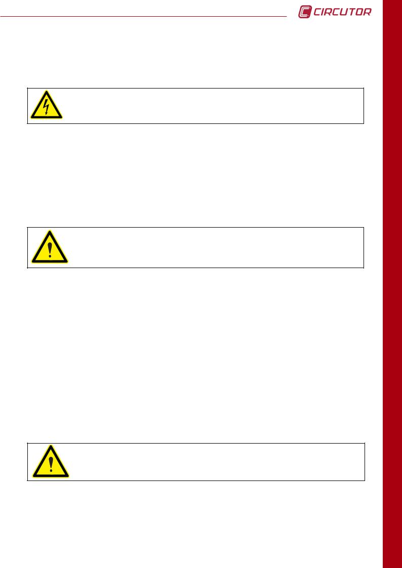
2.3 INSTALLATION METHODS
The figures illustrate the different installation possibilities, permitted by the display screen design. The system design facilitates screwing the panel on (92 +0.8 + 92 +0.8 mm, 138 +0.8 + 138 +0.8 mm and a 103 mm diameter hole).
The figures illustrate how to mount the front part
(display) in a 92x92 mm (3,62 x 3,62 in) hole, a 103 mm (4,06 in) diameter hole and in a 138x138 mm ( 5,43 in) hole.
After inserting the front part, install the mount ring, making sure that the tabs are not blocked (see procedure). Also, assure that the white arrow, which indicates the point where the communications cable and the RJ-45 display screen power supply cable run out, lines up with the arrow on the measuring equipment.
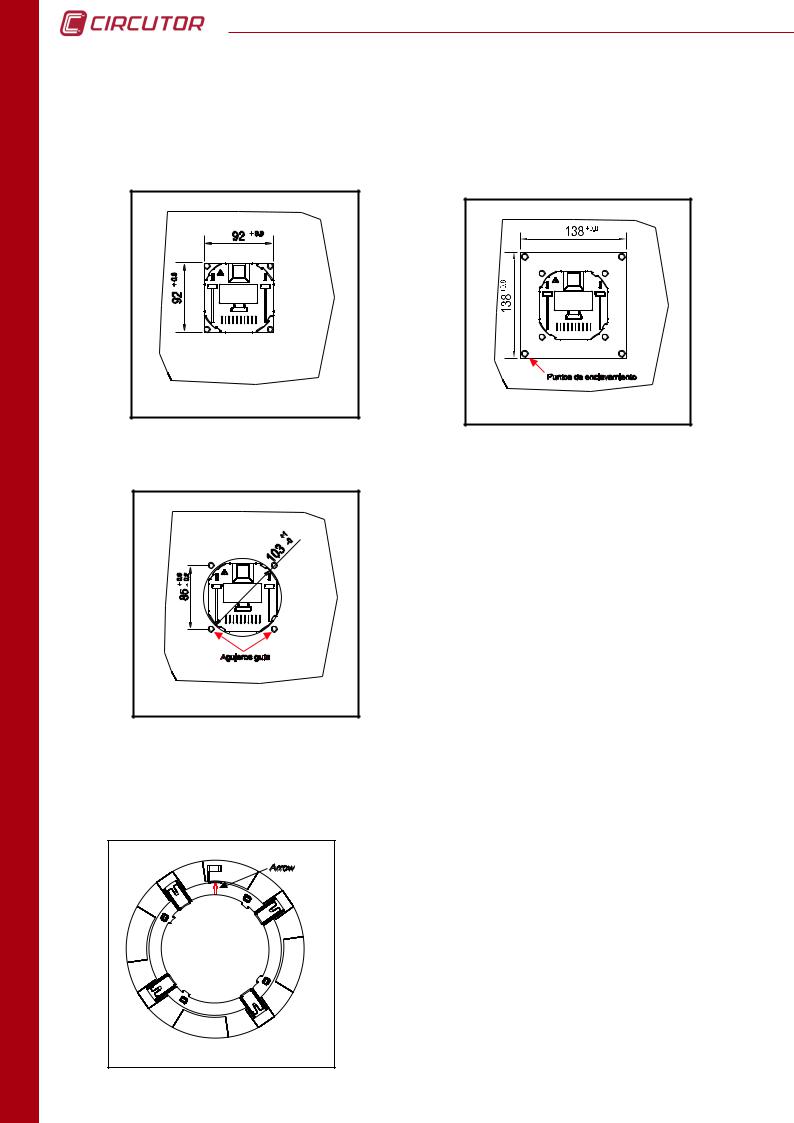
2.3.1 PROCEDURE
The tabs are components used to fasten the system to the panel. When mounting the system, the tabs must be free, and unblocked, so that as pressure is applied to the mount ring the tabs go over the clamp zipper teeth. Similarly, to dismount the panel display the tabs should be blocked, i.e. opened prior to dismounting.

CVMk2
A zoomed view of the previous image is provided in the figure. It provides a detailed view of the movements necessary to lock and unlock CVMk2 display screen mount ring.
As shown in the figure, the guide arrow should point upward and line up with the arrow found on the rear of the viewer or display screen. The arrow points to the position where the RJ-45 communications cable and the display screen power supply cables run out.
The mount diagram is shown in the following figure. The measuring unit can then be mounted on the ring behind the display screen, or it can be installed on a DIN rail and communicate with the display screen via a communication cable and transparent RJ-45 power supply. (See Table 3.1, physical description).
To install the screen in a panel as shows the 2.3 installations methods, you have to use a flat surface of a type 1 enclosure.
INSTALLATION
17

INSTALLATION
18
CVMk2
2.4 SYSTEM CONNECTION
Before connecting the equipment, the following points should be verified:
2.3.1Auxiliary Power Supply Features
2.3.2Maximum Voltage in the Voltage Measuring Circuit
2.3.3Maximum Current in the Current Measuring Circuit
2.3.4Working Conditions
2.3.5Safety
2.4.1AUXILIARY POWER SUPPLY
Standard power supply |
85 |
...265 |
V a.c. |
|
100... |
300 |
V d.c. |
Frequency |
50... |
60 |
Hz |
Optional power supply |
24... |
90 |
V d.c. |
2.4.2 RATED VOLTAGE IN VOLTAGE MEASURING CIRCUIT
Standard rated voltage (*) |
300 / 520 |
Vf-n / Vf-f |
Other voltages (*) |
500 / 866 |
Vf-n / Vf-f |
(*) Current limited. Máximum 0.6 V·A |
|
|
Rated frequency |
45,00...65,00 |
Hz |
Umax = UN x 1.2 |
|
|
2.4.3 RATED CURRENT IN CURRENT MEASURING CIRCUIT
Secondaries .../5A (*) |
5 |
A a.c. |
Secondaries .../1A (*) |
1 |
A a.c. |
(*) limited in voltage |
|
|
Imax = IN x 1.2
2.4.4 WORKING CONDITIONS
Operating temperature |
-10...+40 |
ºC |
Relative Humidity |
5...95 |
% |
CVMk2
2.4.5 SAFETY
Designed for CAT III 300/520 Vac installations in accordance with EN-61010. Protected against electrical shock by class II double insulation.
Designed and identified by the distinctive CE marks.
To increase system capacity with expansion cards prior to handling, modify its connections or replace equipment; the power supply should be shut off and the inputs disconnected from the CVMk2. Handling the system while it is powered up is dangerous.
2.4.6 TECHNICAL FEATURES
VOLTAGE INPUTS
Measuring range |
from 5 to 120% of Un for Un = 300 Vac (f-N) |
|
from 5 to 120% of Un for Un = 520 Vac (f-f) |
||
|
||
Frequency |
45…65 Hz |
|
Maximum measured voltage |
360 Vac |
|
Acceptable overvoltage |
750 Vac |
|
Maximum Consumption (limited current) |
< 0.6 V•A |
|
CURRENT INPUTS |
|
|
Measuring range |
from 1 to 120% of In for In = 5 A |
|
Secondary for the TCs (In) |
1 or 5 A |
|
Primary current measured |
Programmable < 30.000 A |
|
Acceptable overload |
6 A continuous, 100 A t<1 s |
|
Consumption |
< 0.45 V•A |
|
AUXILIARY POWER SUPPLY |
|
|
Power supply |
85 to 265 V ac (50...60 Hz) (consumption < 30 V·A) |
|
90 to 300 V dc (consumption < 25 W) |
||
|
||
MECHANICAL |
|
|
Maximum torque |
0.8 Nm |
|
Maximum wire rigid diameter |
4.5 mm2 (AWG 11) |
When the system is connected, it may be dangerous to touch the terminals. Additionally, dangerous parts may be exposed when covers are opened or when protective components are removed. The system should not be used until it is completely installed.
INSTALLATION
19
INSTALLATION
20
CVMk2
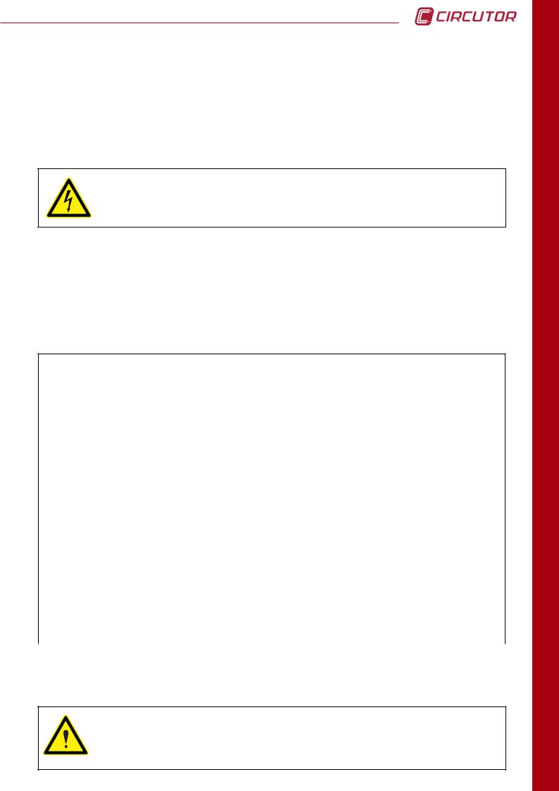
2.5 TERMINALS DESCRIPTION
2.5.1 TAG FOR VOLTAGE AND CT CONNECTIONS
TERMINAL |
DESCRIPTION |
1 |
Current transformer, L1 phase S1 connection |
2 |
Current transformer, L1 phase S2 connection |
3 |
Current transformer, L2 phase S1 connection |
4 |
Current transformer, L2 phase S2 connection |
5 |
Current transformer, L3 phase S1 connection |
6 |
Current transformer, L3 phase S2 connection |
7 |
Current transformer, neutral line S1 connection |
8 |
Current transformer, neutral line S2 connection |
9 |
L1 phase voltage input |
10 |
L2 phase voltage input |
11 |
L3 phase voltage input |
12 |
Input voltage VREF (GND) |
13 |
Input voltage NEUTRAL LINE |
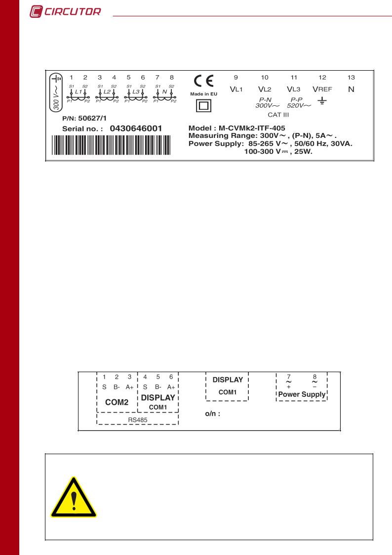
2.5.2 POWER SUPPLY AND COMMUNICATIONS TAG
Product to be protected by an external fuse, model KTK-1 by Bussmann, or similar, rated 600V, 1A. It should be provided with a MCCB or equivalent device to switch off the system from the power supply circuit. The power supply and voltage measuring circuit is connected with cable minimum cross section of 1 mm2 (AWG 17). The current transformer secondary side connection line should have a minimum cross section of 2 mm2 (AWG 14 Cu) and with a minimum temperature rating of 60 ºC.
CVMk2
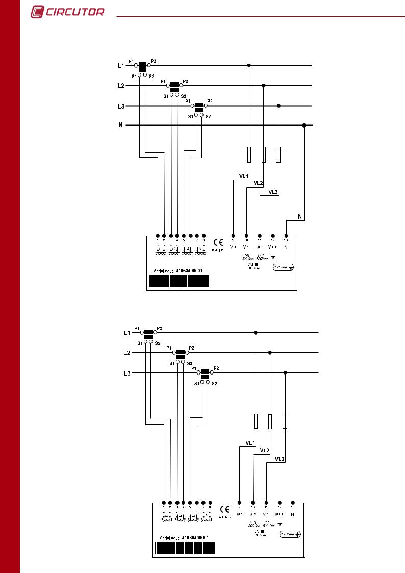
2.6 MEASURING INPUT CONNECTION DIAGRAMS
2.6.1 - 4 CT AND 5 VOLTAGE REFERENCES
2.6.2 - 4 CT AND 4 VOLTAGE REFERENCES
INSTALLATION
21
CVMk2
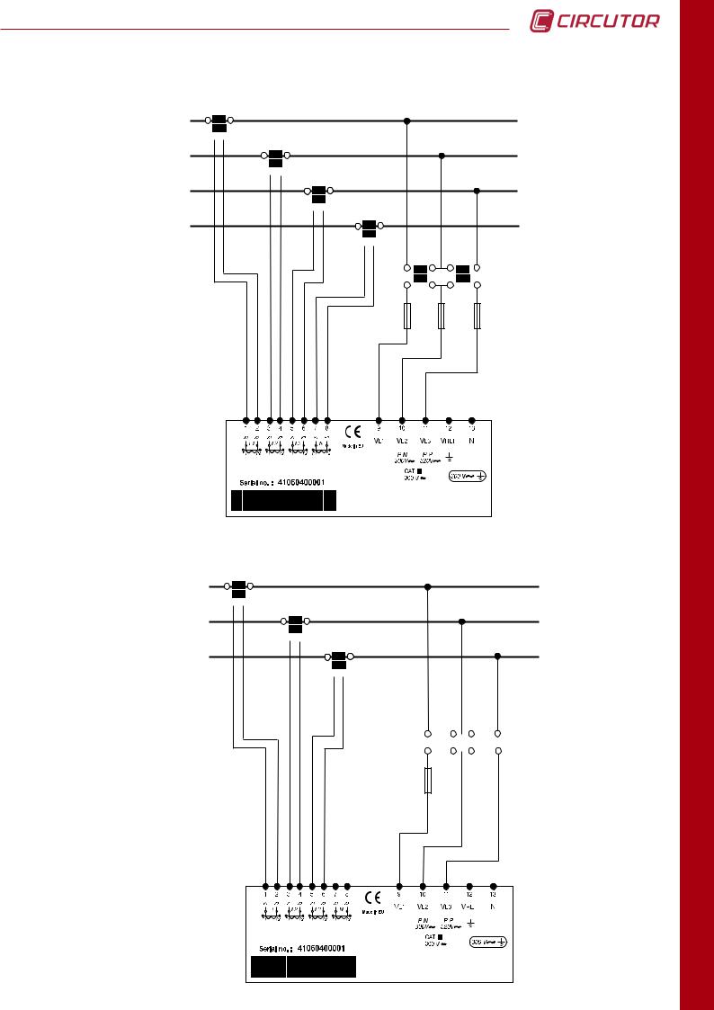
2.6.3 - 3 CT AND 4 VOLTAGE REFERENCES
2.6.4 - 3 CT AND 3 VOLTAGE REFERENCES
INSTALLATION
22
CVMk2
2.6.5 - 4 CT AND 2 VOLTAGE TRANSFORMERS
P1 P2
L1
S1
 S2
S2
P1 P2
L2
S1
 S2
S2
P1 P2
L3
S1
 S2
S2
P1 P2
N
S1
 S2
S2
A B A B
a b a b
VL1
VL2
VL3
2.6.6 - 3 CT AND 2 VOLTAGE TRANSFORMERS
P1 P2
L1
S1
 S2
S2
P1 P2
L2
S1
 S2
S2
P1 P2
L3
S1
 S2
S2
A B A B
|
|
|
|
|
|
|
|
|
|
|
|
|
|
|
|
|
|
|
|
|
|
|
|
|
|
|
|
|
|
|
|
|
|
|
|
|
|
|
|
|
|
|
|
|
|
|
|
a |
|
b |
|
|
a |
|
b |
||||
|
|
|
|
|
|
|
|
|
|
|
|
|
|
|
|
|
|
|
|
|
|
|
|
VL1
VL2
VL3
OPERATION
23
INSTALLATION
24
CVMk2
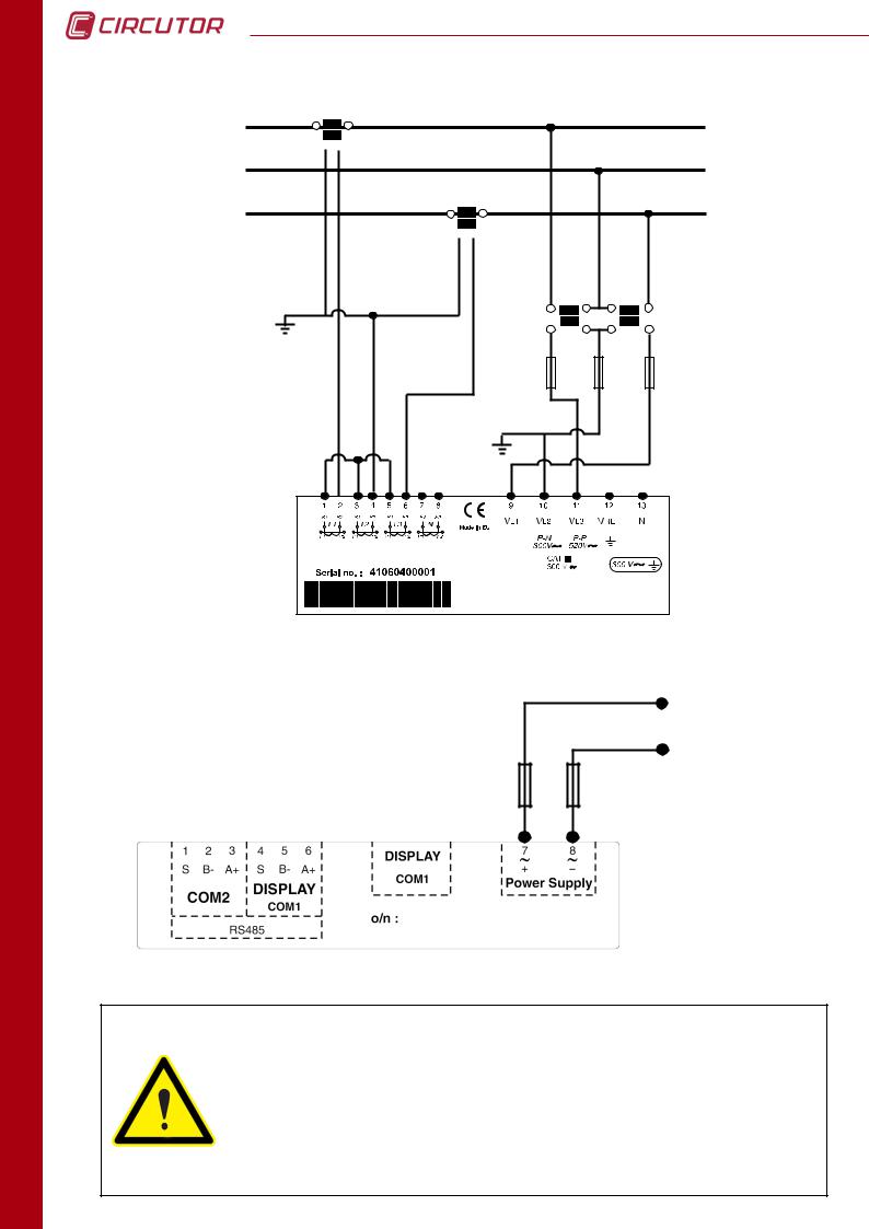
2.6.7 - 2 CT AND 2 VOLTAGE TRANSFORMERS
P1 P2
L1
S1
 S2
S2
L2
P1 P2
L3
S1
 S2
S2
A |
B |
A |
B |
a |
b |
a |
b |
VL1
VL2
VL3
2.7 POWER SUPPLY CONNECTION DIAGRAM
Power supply 85...265 V a.c.
100...300 V c.c. (Standard model)
The system should be connected to a power supply circuit protected by fuses with current ratings between 0.5 and 1 A / 600 V (UL listed). It should be provided with a MCCB or equivalent device to switch off the system from the power supply circuit. The power supply and voltage measuring circuit is connected with cable minimum cross section of 1 mm2 (AWG 17). The current transformer secondary side connection line should have a minimum cross section of 2 mm2 (AWG 14) and with a minimum temperature rating of 60 ºC.
CVMk2
3. OPERATION
3.1 DESCRIPTION OF DEVICE
The external dimensions of the CVMk2 network analyzer are 144 x 144 x 116 mm. It is comprised of a display screen and a measuring module. The display screen communicates with the measuring module via an RJ-45 line, which is "transparent" or direct. The wire layout is provided in the figure below:
DISPLAY SCREEN |
MEASURING EQUIPMENT |
||
PIN |
SIGNAL |
SIGNAL |
PIN |
1 |
V+ |
V+ |
1 |
2 |
GND |
GND |
2 |
3 |
B (-) |
B (-) |
3 |
4 |
Shield |
Shield |
4 |
5 |
Shield |
Shield |
5 |
6 |
A (+) |
A (+) |
6 |
7 |
GND |
GND |
7 |
8 |
V - |
V - |
8 |
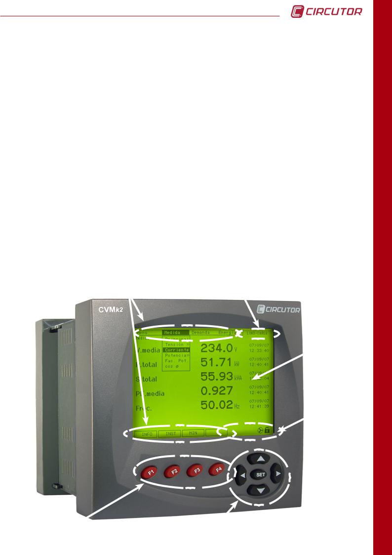
3.1.1 FRONTAL VIEW
MENUS |
MODULE NAME |
|
DISPLAY
SCREEN
ICONS
FUNCTION BUTTONS |
NAVIGATION BUTTONS |
INSTALLATION
25
OPERATION
26
CVMk2
The front is divided into several parts:
a)Display screen.
b)Function buttons.
c)Navigation buttons.
d)SET button.
e)Upper and lower menus.
f)Module name.
g)Icons.
3.1.1.a. Display
The CVMk2 network analyzer incorporates a 320 x 240 pixel, backlit, 1/4 VGA (QVGA) LCD monitor. The monitor surface area is 90 x 70 mm2 (4,5 in). The display screen has backlighting to facilitate reading the parameters when they are presented on the display screen in poor lighting conditions.
CVMk2 allows program a timer to shut off the backlighting after several seconds have passed.
Said timer can be programmed for 10, 90 or 180 seconds. It is also possible to leave the backlighting always ON or always OFF.
To access the display screen properties configuration menu, use the left navigation button to navigate to MENU. Use the SET button or the down arrow button to open the drop-down menu.
Select SYSTEM--PREFERENCES--DISPLAY SCREEN.
WARNING: The maximum working temperature for the 1/4 VGA display screen is 40 ºC. Operating the system above this temperature can quickly deteriorate the equipment or lead to permanent malfunctioning.
3.1.1.b. Function buttons
The system has 4 function buttons on the front side (F1, F2, F3 and F4). The function buttons are used to access the different menus that appear on the bottom of the display.
3.1.1.c. Navigation buttons
On the front side, the system has 4 arrow buttons used to navigate through the different menus that appear on the lower side of the screen. Press the left arrow button to exit at any time the current menu.
3.1.1.d. SET button
This button is used to access the menu that is selected with the cursor and to confirm any change before to press OK (F4). Is necessary to press SET to store any chage.
3.1.1.e. Upper and lower menus
The upper and lower menus change based on the current screen. A detailed description of all the menus and the options in each menu is provided in the upcoming chapters.

CVMk2
3.1.1.f. Module name
The measuring module currently being viewed is defined on this part of the display screen. This is important in facilities where measuring modules are communicating with one single display screen.
3.1.1.e. Icons
 Editable configuration menu (without password).
 Configuration menu locked with password.
 None of the voltages for the phases are connected, or they are not detected.
 Voltage is only detected at the phase 1 input.
 Voltage is only detected at the phase 2 input.
 Voltage is only detected at the phase 3 input.
 Voltage is only detected at the phase 1 and 2 inputs.
 Voltage is only detected at the phase 1 and 3 inputs.
 Voltage is only detected at the phase 2 and 3 inputs.
 Voltage is detected at the phase 1, 2 and 3 inputs.
 Correct μSD memory status.
 Incorrect μSD memory status.
 Extraction of μSD card enabled.
 Short circuit or hole detected. This only appears during the event.
 Overvoltage detected. This only appears during the event.
 Switching detected. This only appears during the event.
 There is no consumption and no generation.
 Generation
 Consumption.
OPERATION
27
CVMk2
3.2. START-UP
Before power ON the device, make sure that all the cables are properly connected.
A bad connection can cause serious injuries to the personnel that are working on the equipment and can damage the equipment.
When power supply is connected to the CVMk2, the system will show an initial presentation and initialize its internal software indicating the firmware version on the display screen. After a time of searching, it will also display the firmware versions of the modules that are connected to the COM 1 DISPLAY port as well as the cards that are inserted in each one of the modules.
Once initialization is complete, the CVMk2 will display the switched module's real time values on the main screen.
The CVMk2 principal screen changes. This is because the system will keep a memory the last screen that was viewed for more than 20 seconds before disconnected. This screen will be displayed the next time the display is turn on except if it is an expansion card screen. They are not stored in memory.
Once the CVMk2 has been installed, is recommended to restart the meter and the maximums and minimums of the device. It is possible that the installation process will produce some recorded parameters outside the range of normal working and subsequently affect the display of records in graphs or tables.
CVMk2
4. CONFIGURATION
The analyzer does not store programming changes that are made until programming is complete. These changes are confirmed by pressing SET and after the OK button. If the system is reset before said programming is complete or
if the user exits the menu using the ESC button, the configuration settings will not be stored in memory. To access to the configuration menu, refer to Chapter 4.
Measurement, communication and expansion card parameters (if available) can be modified from the configuration menu.
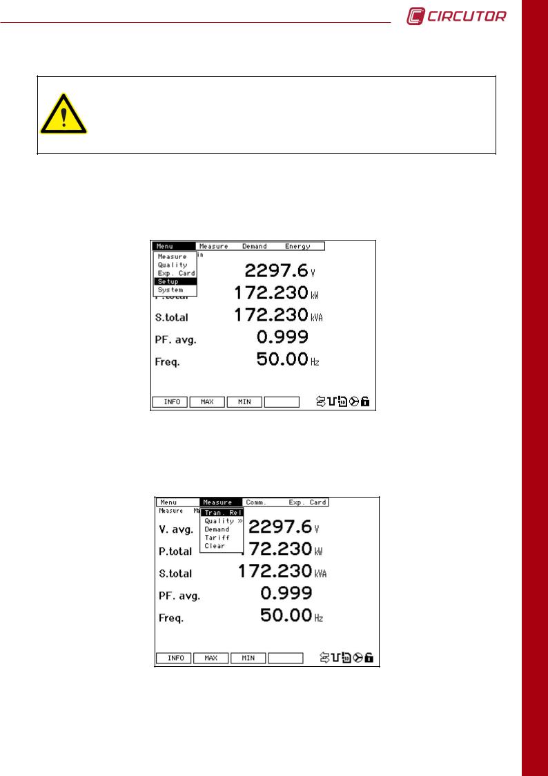
To access the configuration inside the MENU, select SETUP and confirm with the SET key. The menu on the top of the screen will appear as seen in the following figure.
4.1 MEASURING
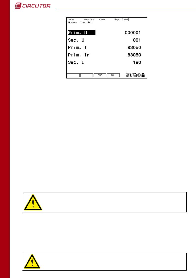
In the MEASURE menu, the list of voltage and current transformers can be accessed. To modify the transformer configuration parameters, press the EDIT button (F4).
Position the cursor in the first line of parameters (primary voltage). Use the up-down arrow
buttons to move the cursor to the desired parameter. Press SET to enter the numeric value to be modified. The cursor will be positioned over the first digit, corresponding to the largest value.
Use the left/right arrow buttons to navigate from one digit to another and the up/down arrow buttons to increase/decrease the value of the digit.
CONFIGURATION
29
CONFIGURATION
30
CVMk2
Parameters that can be configured on this screen follow:
• PRIM. U.: Primary on the voltage transformers. If it does not exist, program 1. The maximum configurable value is 999999.
• SEC. U.: Secondary on the voltage transformers. If it does not exist, program 1. The maximum configurable value is a 3 digit number 999.
•PRIM. I.: Primary on the current transformer. The maximum configurable value is 30000.
•PRIM. IN.: Primary on the current transformer for the neutral line. The maximum
configurable value is 30000.
The default value is 5. If it is desirable for the CVMk2 to show the neutral line current that is calculated, configure 0.
• SEC. I.: Secondary on the current transformer. It is possible to program 5 or 1.
To store the modified parameters in memory, press SET and confirm with OK (F4). To exit without saving changes press ESC (F3).
WARNING: The CVMk2 power calculation is limited according to the following ratio:
(Prim V) x (Prim I) < 45.000.000
4.2. QUALITY
To access the power supply quality parameters configuration screen, position the cursor over
QUALITY and press SET. Two options are provided in the quality menu, QUALITY and EVENTS.
CVMk2 has no battery. When supply falls down the analyzer do not store electrical parmeters and no quality events. Is very important to guarantee the supply of the device from an interrupted source (Batery, SAI, ...)
Loading...