

Page 1
Energy manager
line-EDS-PS
line-EDS-PSS
line-EDS-PSS-PRO
INSTRUCTION MANUAL
(M259B01-03-21A)
Page 2

line-EDS-PSxxx
2
Instruction Manual
Page 3
line-EDS-PSxxx
SAFETY PRECAUTIONS
Follow the warnings described in this manual with the symbols shown below.
DANGER
Warns of a risk, which could result in personal injury or material damage.
ATTENTION
Indicates that special attention should be paid to a specific point.
If you must handle the unit for its installation, start-up or maintenance, the following should be
taken into consideration:
Incorrect handling or installation of the unit may result in injury to personnel as well as damage to the
unit. In particular, handling with voltages applied may result in electric shock, which may cause death
or serious injury to personnel. Defective installation or maintenance may also lead to the risk of fire.
Read the manual carefully prior to connecting the unit. Follow all installation and maintenance instructions throughout the unit’s working life. Pay special attention to the installation standards of the
National Electrical Code.
Refer to the instruction manual before using the unit
In this manual, if the instructions marked with this symbol are not respected or carried out correctly, it can result
in injury or damage to the unit and /or installations.
CIRCUTOR, SA reserves the right to modify features or the product manual without prior notification.
DISCLAIMER
CIRCUTOR, SA reserves the right to make modifications to the device or the unit specifications set
out in this instruction manual without prior notice.
CIRCUTOR, SA on its web site, supplies its customers with the latest versions of the device specifications and the most updated manuals.
www.circutor.com
CIRCUTOR, recommends using the original cables and accessories that are supplied
with the device.
Instruction Manual
3
Page 4

line-EDS-PSxxx
CONTENTS
SAFETY PRECAUTIONS .........................................................................................................................................................3
DISCLAIMER ..........................................................................................................................................................................3
CONTENTS .............................................................................................................................................................................4
REVISION LOG .......................................................................................................................................................................5
SYMBOLS ...............................................................................................................................................................................5
1. VERIFICATION UPON RECEPTION ....................................................................................................................................6
2. PRODUCT DESCRIPTION ................................................................................................................................................6
3. INSTALLATION OF THE DEVICE ......................................................................................................................................7
3.1.- PRELIMINARY RECOMMENDATIONS ........................................................................................................................7
3.2.- INSTALLATION .........................................................................................................................................................7
3.3.-72 x 72 mm PANEL ADAPTER ..................................................................................................................................8
3.4.- DEVICE TERMINALS .................................................................................................................................................9
3.5.- EXPANSION WITH OTHER DEVICES .........................................................................................................................9
3.5.1.- Line-M-EXT-PS POWER ADAPTER ............................................................................................................... 10
3.5.2.- INSTALLATION ...............................................................................................................................................11
3.6.- CONNECTION DIAGRAM ......................................................................................................................................... 13
4. OPERATION .................................................................................................................................................................. 14
4.1.- OPERATING PRINCIPLE .......................................................................................................................................... 14
4.2.- LED INDICATORS ................................................................................................................................................... 14
4.3- DIGITAL OUTPUTS .................................................................................................................................................16
5. COMMUNICATIONS ........................................................................................................................................................ 17
5.1- RS-485 COMMUNICATIONS ..................................................................................................................................... 17
5.1.1.- CONNECTIONS ............................................................................................................................................... 17
5.2- Wi-Fi COMMUNICATIONS ....................................................................................................................................... 18
5.2.1.- USAGE ENVIRONMENT AND HEALTH ........................................................................................................... 18
5.2.2.- Wi-Fi COMMUNICATIONS .............................................................................................................................. 18
6. CONFIGURATION WEBSITE ............................................................................................................................................ 19
6.1- NETWORK SETUP................................................................................................................................................... 20
6.2- TIME SETUP ............................................................................................................................................................ 21
6.3- ACTIVE MODE ......................................................................................................................................................... 21
6.4- SECURITY SETUP ....................................................................................................................................................22
6.5- INFORMATION ........................................................................................................................................................22
7. TECHNICAL FEATURES ..................................................................................................................................................23
8. MAINTENANCE AND TECHNICAL SERVICE ...................................................................................................................25
9. GUARANTEE ..................................................................................................................................................................25
10. CE CERTIFICATE ...........................................................................................................................................................26
4
Instruction Manual
Page 5
line-EDS-PSxxx
REVISION LOG
Table 1: Revision log.
Date Revision Description
05/20 M259B01-03-19A First Version
07/20 M259B01-03-20A
11/20 M259B01-03-20B
07/21 M259B01-03-21A
Changes in the following sections:
2. - 3.6. - 4.1.
Changes in the following sections:
7.
Changes in the following sections:
7.
SYMBOLS
Table 2: Symbols.
Symbol Description
In accordance with the relevant European directive.
In accordance with the CMiM directive.
Device covered by European Directive 2012/19/EC. At the end of its useful life, do not leave the
device in a household refuse bin. Follow local regulations on electronic equipment recycling.
Direct current.
~
Alternating current.
Note: The images on the devices are for illustrative use only and may differ from the original device.
Instruction Manual
5
Page 6
1. VERIFICATION UPON RECEPTION
Upon reception of the device check the following points:
a) The device meets the specifications described in your order.
b) The device has not suffered any damage during transport.
c) Perform an external visual inspection of the device prior to switching it on.
d) Check that it has been delivered with the following:
- An installation guide
If any problem is noticed upon reception, immediately contact the transport company and/or CIRCUTOR’s after-sales service.
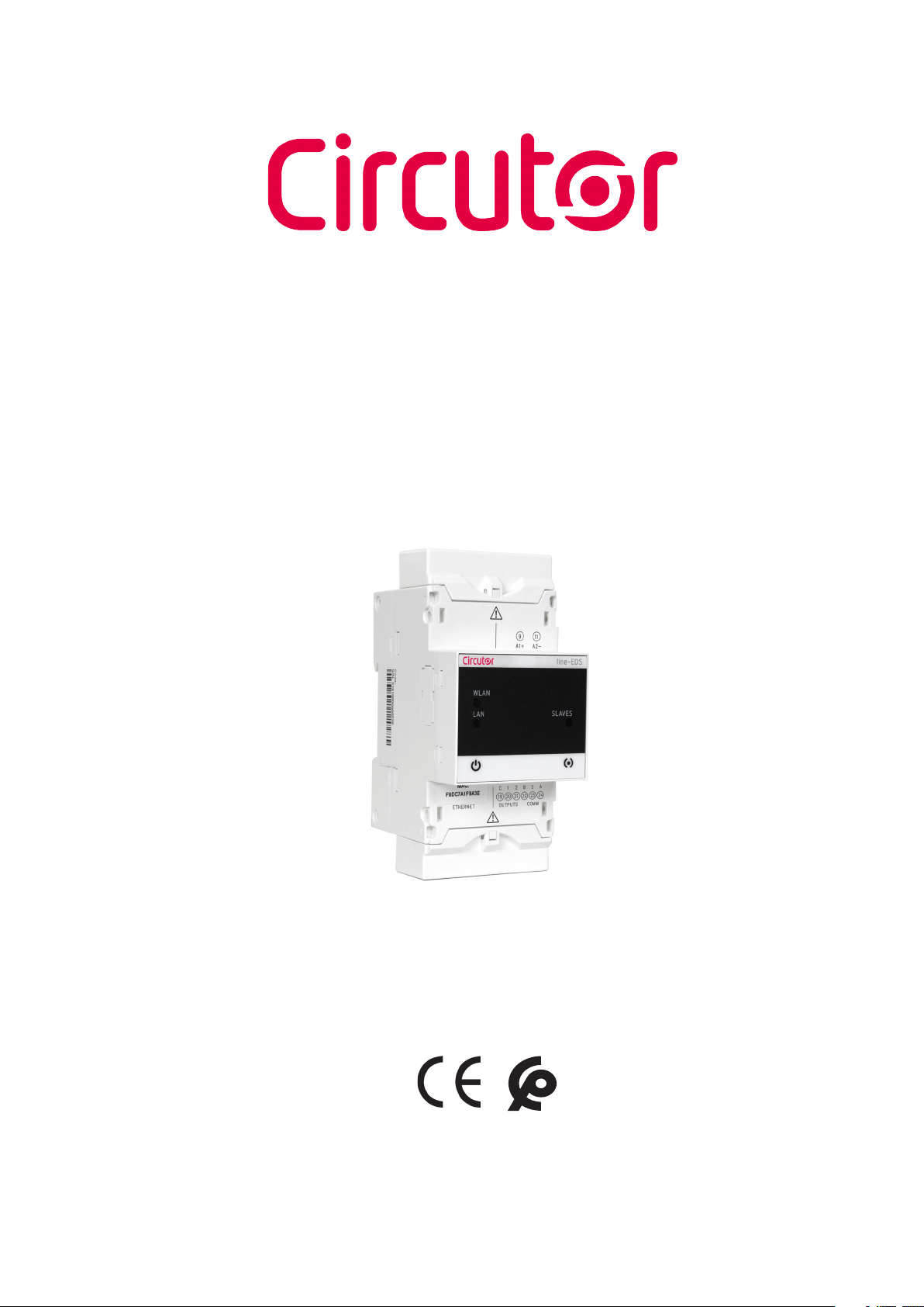
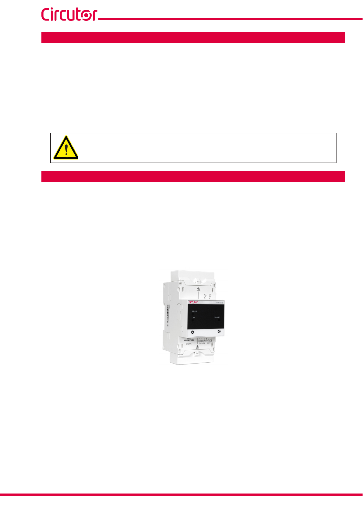
2.- PRODUCT DESCRIPTION
line-EDS-PSxxx
line-EDS-PSxxx is a device that works as connector between field devices with Modbus RTU or Modbus TCP communications and the PowerStudio energy management software.
Circutor has 3 models:
line-EDS-PS, with embedded PowerStudio.
line-EDS-PSS, with embedded PowerStudio SCADA.
line-EDS-PSS-PRO, with embedded PowerStudio SCADA DELUXE.
The device features:
- 5 indication LEDs
- 2 digital outputs.
- RS-485 and Ethernet communications.
- Wi-Fi connection.
The line-EDS-PSxxx features a Web server to set up the device and display the variables of all the
modules or devices connected to it
6
Instruction Manual
Page 7
line-EDS-PSxxx
3. INSTALLATION OF THE DEVICE
3.1.- PRELIMINARY RECOMMENDATIONS
In order to use the device safely, personnel operating it must follow the safety measures that comply with the standards of the country where it is to be installed; operators
must wear the required personal protective equipment (rubber gloves, approved facial
protection and flame-resistant clothing) to prevent injuries from electric shock or arcs
caused by exposure to current-carrying conductors, and they must heed the various
warnings indicated in this instruction manual.
The line-EDS-PSxxx device must be installed by authorised, qualified personnel.
The power supply plug must be disconnected before handling, altering the connections or replacing
the device. It is dangerous to handle the device while it is powered.
Cables must always be kept in perfect condition to avoid accidents or injury to personnel or installations.
The manufacturer of the device is not responsible for any damage resulting from failure by the user
or installer to heed the warnings and/or recommendations set out in this manual, nor for damage
resulting from the use of non-original products or accessories or those made by other manufacturers.
Do not use the device to perform any operation if you detect any anomaly or malfunction.
Before carrying out maintenance, repair or handling of any of the device’s connections,
the device must be disconnected from all power sources, both from the device’s own
power supply and the measurement’s.
Contact the after-sales service if you detect that the device is not working properly.
3.2.- INSTALLATION
The device must be installed on an electric panel or enclosure, at tached to a DIN rail (IEC 60715).
When the device is on, its terminals, opening covers or removing elements may expose
the user to parts that are hazardous to touch. Do not use the device until it is fully
installed.
The device must be connected to a power supply circuit protected by gl type (IEC 269) or M type fuses,
between 0.5 and 2A. It must be fitted with a circuit-breaker or equivalent device to disconnect the
device from the mains supply.
The power supply circuit must be connected with a 1mm² minimum cross-section cable.
Instruction Manual
7
Page 8
line-EDS-PSxxx
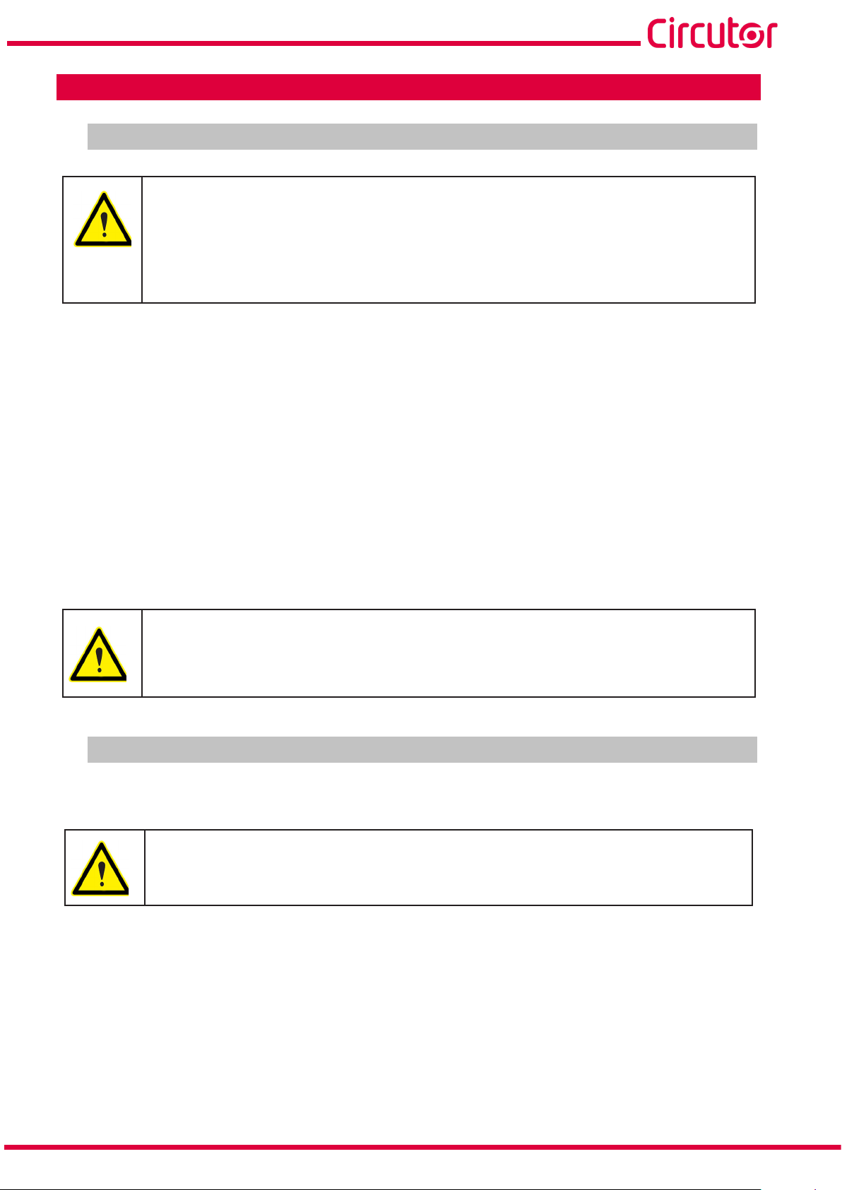
3.3.- PANEL ADAPTER 72 x 72 mm
Note: The 72 x 72 mm panel adapter is a separately sold accessory.
CIRCUTOR has a panel adapter for the line-EDS-PSxxx devices for their installation in 72 x 72 mm
panels.
Figure 1 illustrates how the panel adapter connects to a line-EDS-PSxxx.
Before installing the adapter, the device must be disconnected from all power and
measurement supplies.
Figure 1: Installation of the panel adapter.
Table 3: Technical characteristics of the Panel Adapter.
Technical Specifications
Protection degree IP40
Casing Self-extinguishing V0 plastic
68 mm
68 mm
Figure 2: Cut in the panel.
8
Instruction Manual
Page 9
line-EDS-PSxxx
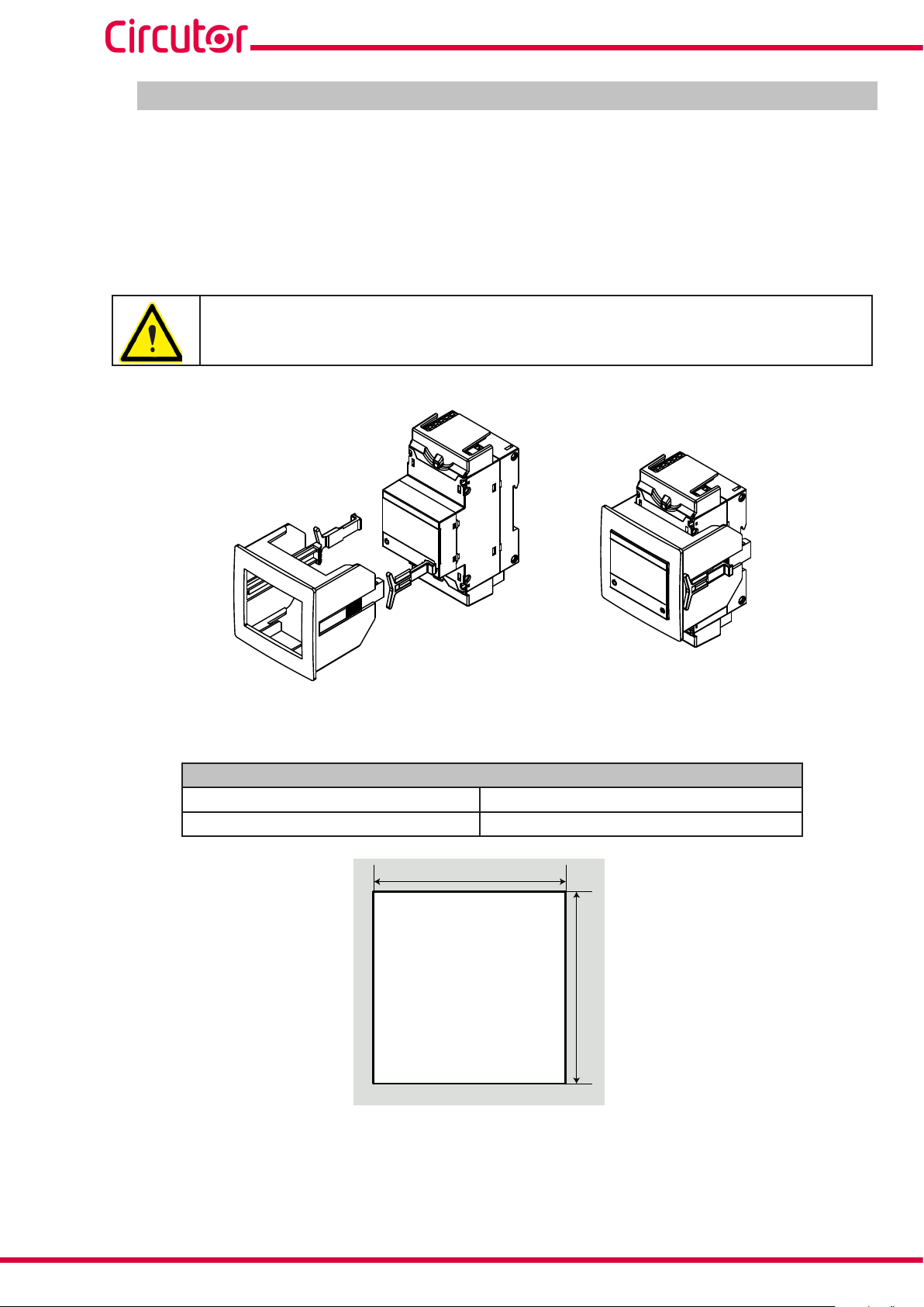
3.4.- DEVICE TERMINALS
24
A1
A2
24
23
22
21
20
19
23
22
21
20
Ethernet
Figure 3: Device terminals: Upper - Lower.
Table 4: List of terminals.
Device terminals
A1: Power supply 21: 1, Digital output 1
A2: Power supply 20: 2, Digital output 2
24: A+, RS-485 19: C, Common of digital outputs
23: S, GND for RS-485 Ethernet, Ethernet connection
22: B-, RS-485
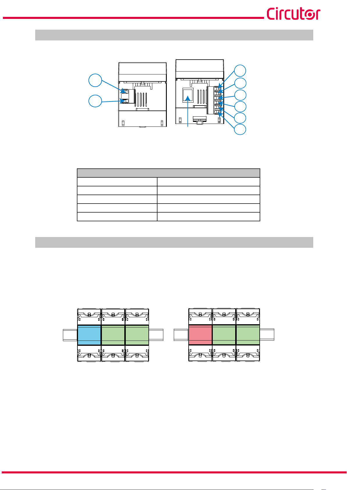
3.5.- EXPANSION WITH OTHER DEVICES
The line-EDS-PSxxx devices can be expanded with other devices in the line range, the line-CVM and
line-M expansion modules.
19
The line-EDS-PSxxx and line-CVM devices enable up to 2 expansion modules to be directly connected
to their right-hand side
(1)
.
line-EDS line-M line-M
line-CVM
line-M line-M
Figure 4: line-EDS-PSxxx and line CVM expansion module connection.
(1)
Expansion module types: line-M-4IO-R, line-M-4IO-T, line-M-4IO-RV and line-M-4IO-A.
In installations with line-EDS-PSxxx devices, a total of up to seven devices may be connected to their
right-hand side.
Instruction Manual
9
Page 10

line-EDS-PSxxx
line-EDS line-M line-M
line-CVM
line-M line-M
line-CVM line-CVM
Figure 5: Typical installation of a line-EDS-PSxxx with 7 devices.
Note: An installation may only be fitted with one line-EDS-PSxxx device.
Note: In installations without line-EDS-PSxxx devices, only one line-CVM device may ne installed.
Note: All line-EDS-PSxxx and line-CVM devices must be connected to the auxiliary power supply.
3.5.1.- Line-M-EXT-PS POWER ADAPTER
Line-M-EXT-PS is a power adapter belonging to the line family of devices. The module connects to the
left-hand side of the devices to be fed. It can supply up to 10 VA, allowing it to power a limited number
of devices.
The maximum set it can supply is: 1 line-EDS-PSxxx + 1 line-CVM + 1 line-M (Figure 6).
line-M-EXT-PS
line-EDS line-M
line-CVM
Figure 6: Maximum set a line-M-EXT-PS can supply.
Multiple line-M-EXT-PS devices can be connected to supply sets with power above 10VA. Each line-
M-EXT-PS will power the devices connected to its right-hand side (Figure 7).
line-M-EXT-PS
line-EDS line-M line-M
Figure 7: Multiple line-M-EXT-PS connection.
line-M-EXT-PS
line-CVM
line-M line-M
line-M-EXT-PS
line-CVM line-CVM
Note: None of the line-EDS-PSxxx or line-CVM devices should be connected to the auxiliary power
supply.
10
Instruction Manual
Page 11
line-EDS-PSxxx
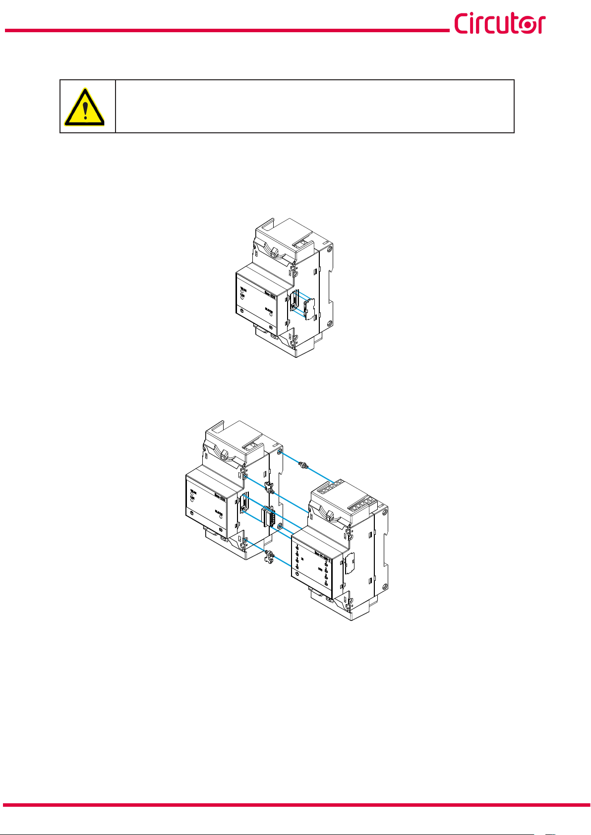
3.5.2.- INSTALLATION
Before installing a new device, it must be disconnected from all power supplies.
The correct steps to connect the devices are:
1.- Using a flat head screwdriver, remove the expansion connector’s protective covers located on the
side of the devices, (Figure 8).
Figure 8: Installation step 1.
2.- Insert the expansion connector and fastening clips into one of the devices (Figure 9).
Figure 9: Installation step 2.
3.- Connect both devices and fasten them by pushing the front clips down (Figure 10).
Instruction Manual
11
Page 12

line-EDS-PSxxx
Figure 10: Installation step 3.
For correct installation of all devices, please refer to the instruction manual for the
different models:
M237B01-01-xxx: Instruction Manual for line-CVM devices.
M239B01-03-xxx: Instruction Manual for line-M expansion modules.
12
Instruction Manual
Page 13

line-EDS-PSxxx
3.6.- CONNECTION DIAGRAM
Con navegador Web
compatible con HTML5
With a browser
compatible with HTML5
Con navegador Web
compatible con HTML5
With a browser
compatible with HTML5
PC
PC
Wi-Fi
Ethernet
Ethernet
WLAN
LAN
INTERNET
ROUTER
line-EDS
SLAVES
SERVIDOR / SERVER
Wi-Fi
A
S
B
RS-485
Instruction Manual
Figure 11: line-EDS-PS, line-EDS-PSS and line-EDS-PSS-PRO connection diagram.
13
Page 14

line-EDS-PSxxx
4. OPERATION
4.1.- OPERATING PRINCIPLE
The line-EDS-PSxxx is a device that works as connector between field devices with Modbus RTU or
Modbus TCP communications and the PowerStudio energy management software.
The line-EDS-PSxxx models connect to field devices with Modbus via RS-485, Wi-Fi or via a Modbus
TCP Ethernet connection, and they send data to the PowerStudio energy management software.
Three device models are available, depending on the management software:
line-EDS-PS, for the embedded PowerStudio software.
line-EDS-PSS, for the PowerStudio SCADA software.
line-EDS-PSS-PRO, pfor the PowerStudio SCADA DELUXE software.
4.2.- LED INDICATORS
The devices have 5 indicating LEDs:
WLAN
LAN
CPU
line-EDS
WLAN
LAN
Figure 12: LED indicators.
SLAVES
SLAVES
ALARMA
ALARM
14
CPU, Device status:
Table 5: CPU LED.
LED Description
Flashing (white color)
CPU
Device powered
Instruction Manual
Page 15
line-EDS-PSxxx
LAN, Ethernet connection
LED Description
LAN
WLAN, Wi-Fi connection:
LED Description
WLAN
Table 6: LAN LED.
On (green color)
Connection to a local network
Flashing (green color)
Activity in the network
Table 7: WLAN LED.
On (blue color)
Connection to a Wi-Fi network
Flashing (blue color)
Activity in the Wi-Fi network
ALARM:
Table 8: ALARM LED.
LED Description
On (red color)
CPU
Alarm activated
SLAVES, Connection with slave device:
Table 9: SLAVES LED.
LED Description
SLAVES
On (red color)
The slave device doesn’t communicate
Instruction Manual
15
Page 16
line-EDS-PSxxx
4.3- DIGITAL OUTPUTS
The device has 2 digital outputs, optoisolator NPN transistors (terminals 19, 20 and 21 in Figure 3).
line-EDS
WLAN
LAN
SLAVES
21
19
C
Salidas de transistor
Transistor outputs
Carga
Load
Fuente externa
External load
12
Figure 13: Digital outputs.
16
Instruction Manual
Page 17
line-EDS-PSxxx
5. COMMUNICATIONS
5.1- RS-485 COMMUNICATIONS
line-EDS-PSxxx devices have an RS-485 communications port.
5.1.1.- CONNECTIONS
The RS-485 cable must be wired using twisted pair cable with mesh shield (minimum 3 wires), with a
maximum distance of 1200 meters between the line-EDS-PSxxx and the slave devices.
In this bus we can connect a maximum of 32 slave devices.
SERVIDOR / SERVER
Ethernet
WLAN
LAN
line-EDS
line-EDS
SLAVES
A
S
B
CVM-E3-MINI
A(+)
S
B(-)
RS-485
Figure 14: RS-485 connection diagram.
CVM-E3-MINI
A(+)
A
B(-)
B
S
S
A(+)
A
B(-)
B
S
S
Instruction Manual
17
Page 18
line-EDS-PSxxx
5.2- Wi-Fi COMMUNICATIONS
5.2.1.- USAGE ENVIRONMENT AND HEALTH
Wireless communications emit radio frequency electromagnetic energy, like other radio devices.
Because wireless communications operate under the guidelines found in radio frequency standards
and recommendations, they are safe for users to use.
In some settings and situations the use of wireless communications may be restricted by the building’s
owner of representatives of the organisation.
These may include:
Use of wireless connections on board aircraft, in hospitals or near service stations, blasting
areas, medical implants or electronic medical devices implanted in the human body (pacemakers, etc.).
In any other setting where the risk of interference with other devices or services is a hazard.
If you are not sure of the applicable usage policy for wireless devices in a specific organisation (airport,
hospital, etc.) we recommend requesting permission to use wireless communications.
5.2.2.- Wi-Fi COMMUNICATIONS
Wi-Fi is one of the most widely-used wireless technologies today, used to connect electronic devices
and exchange information between them without a physical connection.
The line-EDS-PSxxx has Wi-Fi communications over the 2.4 GHz band, in accordance with the IEEE
802.11 ac / a / b / g / n standards.
Table 10: Security features of Wi-Fi communications.
Security features of Wi-Fi communications
Security protocol WPA2
18
Instruction Manual
Page 19
line-EDS-PSxxx
6. CONFIGURATION WEBSITE
The internal configuration website of the line-EDS-PSxxx models can be found at:
http://xxx.xxx.xxx/html/setup.html
http://name_dhcp/html/setup.html
http://100.0.0.1/html/setup.html
Where: xxx.xxx.xxx is the IP address assigned by the user.
name_dhcp is the name assigned and authenticated by the name server of the local area
network (LAN).
Note: The device leaves the factory with DHCP activated.
Note: To find the device in a local network, a crossover cable has to be used to access the device’s local
IP: 100.0.0.1 with a subnet mask 255.255.255.0
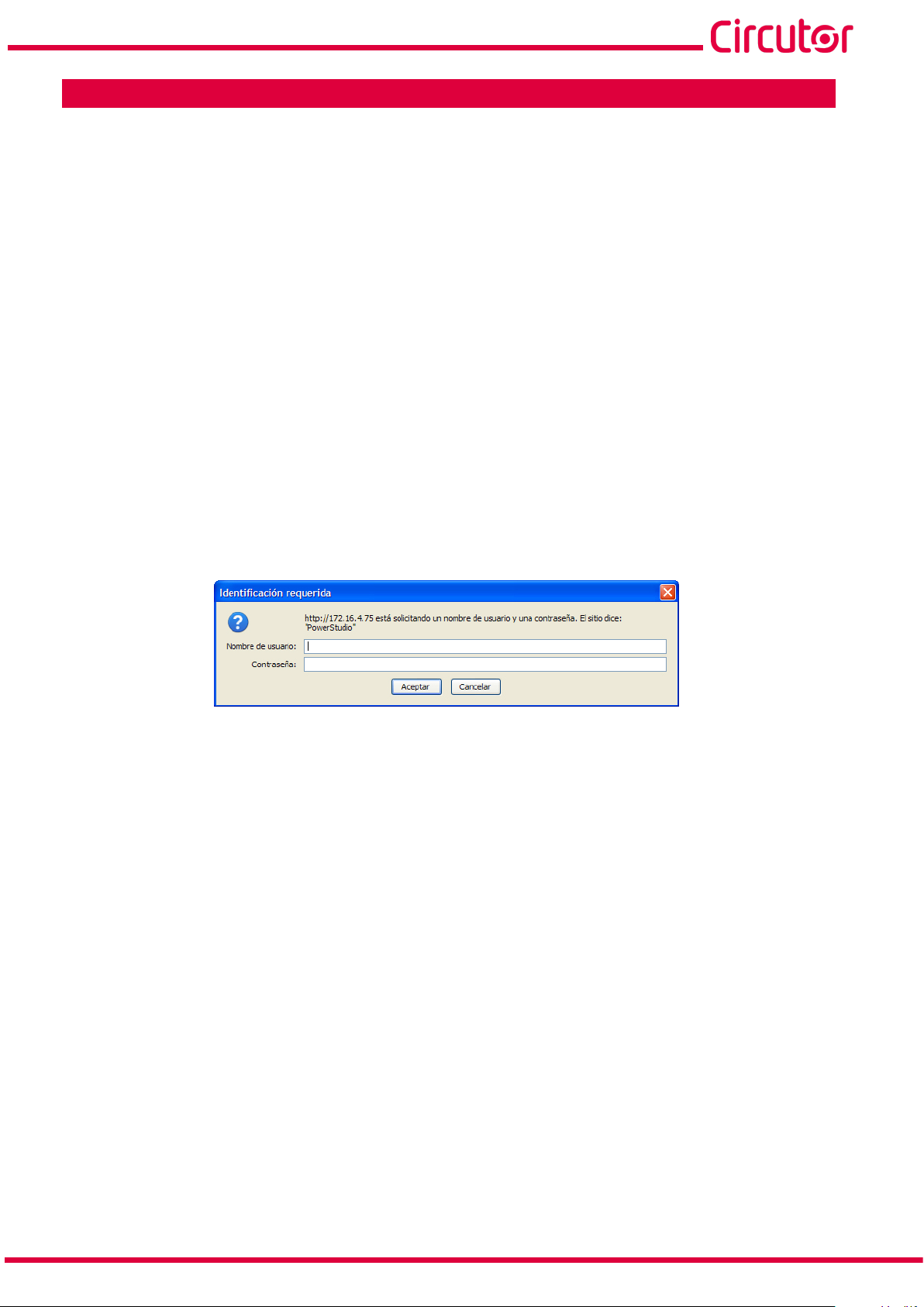
If a username and login password have been set up, when trying to access via the web, the website
requests these login parameters on the following pop-up screen, Figure 15.
Figure 15: Username and password.
Figure 16 shows the configuration website.
Instruction Manual
19
Page 20
line-EDS-PSxxx
Figure 16: Configuration website: line-EDS-PSxxx.
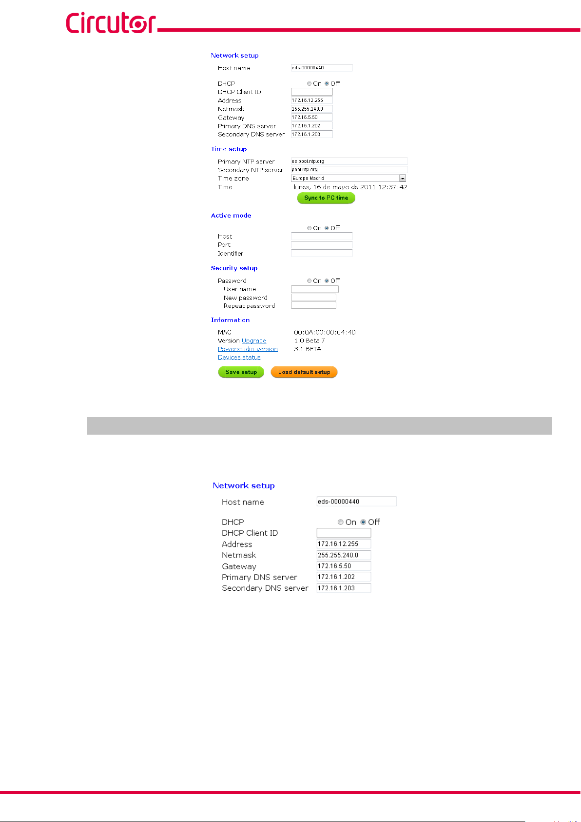
6.1- NETWORK SETUP
In this section, the Ethernet communications of the line-EDS-PSxxx are configured.
Figure 17: Configuration website: Network setup.
Host name: Identifying name within the local network.
DHCP: If DHCP is enabled (DHCP On), the IP address is dynamically assigned by a central server and
no further parameters need to be configured.
If this option is disabled, the IP address is fixed and the following parameters need to be configured:
20
DHCP Client ID: Device ID.
Address: IP address.
Netmask: IP subnet mask.
Gateway: Gateway.
Instruction Manual
Page 21
line-EDS-PSxxx
Primary DNS server: Address of the primary DNS server.
Secondary DNS server: Address of the secondary DNS server.
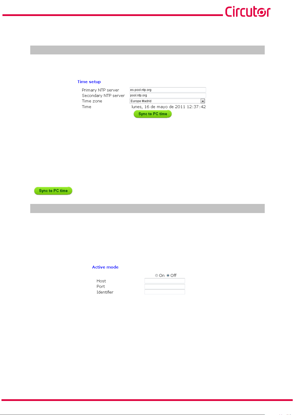
6.2- TIME SETUP
In this section, the line-EDS-PSxxx time parameters are configured.
Figure 18: Configuration website: Time setup.
Primary NTP server: Watch synchronisation protocol address, Network Time Provider.
Secondary NTP server: Network Time Provider’s secondary address, in case NTP 1 fails.
Time zone: Time zone where the device is located.
Press to synchronise the time on the device with the computer.
6.3- ACTIVE MODE
In this section, the parameters of the AMB (Active Mode Bridge) system are configured. The AMB
system inverts the role of the process for connecting remote devices. The devices are the ones that
initiate the communication process with the connection server located on a central computer, creating
a transparent communication tunnel between the device and server. This avoids the requirement of
having a fixed IP or DynDNS system at the user’s remote control sites.
Figure 19: Configuration website: Active mode.
Active mode: Turns the AMB service on or off. If this option is on, the following parameters need to
be configured:
Host: Destination IP address to which the device connects actively.
Port: Access port to the server where the AMB connecting software has been installed.
Identifier: Each device connected to the AMB system must have an identifier or alias to enable
the connection to the server.
Instruction Manual
21
Page 22
line-EDS-PSxxx
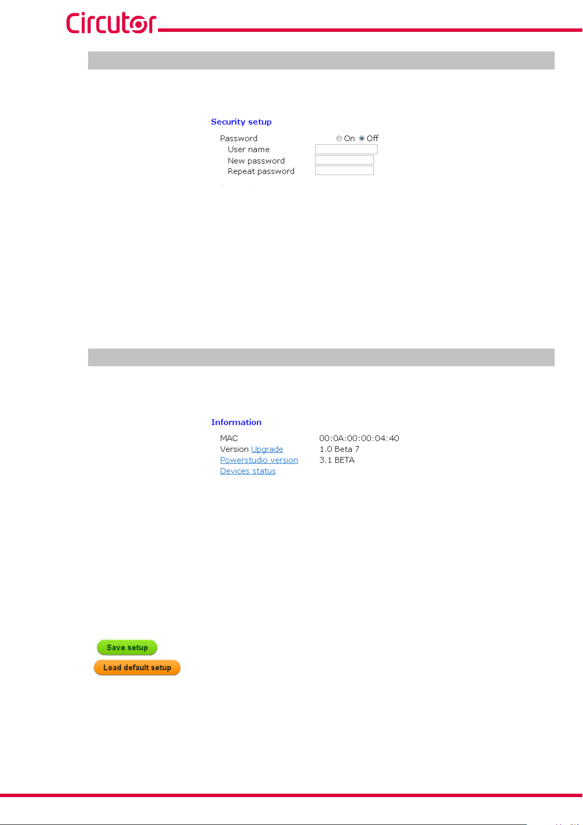
6.4- SECURITY SETUP
In this section, the line-EDS-PSxxx password is configured.
Figure 20: Configuration website: Security setup.
Password: The login password for the device can be on or off. If on, the following parameters need
to be configured:
User name: username.
New password: login password.
Repeat password: repeat the login password.
6.5- INFORMATION
This section shows the information on the line-EDS-PSxxx device.
Figure 21: Configuration website: Information.
MAC: MAC address.
Version Upgrade: Firmware version of the device.
Powerstudio version: PowerStudio software version.
Device status: Status of the device.
22
Press to save the device configuration.
Press to load the default parameters.
Instruction Manual
Page 23
line-EDS-PSxxx
7. TECHNICAL FEATURES
AC Power supply
Rated voltage
Frequency
Consumption
Installation category
DC Power supply
Rated voltage 190 ... 300 V
Consumption
Installation category
Digital outputs
Quantity 2
Type Optocoupler (Open-collector)
Maximum voltage 48V
Maximum current 120 mA
Maximum frequency 500 Hz
Pulse width 1 ms
RS-485 communication
Bus RS-485
Protocol Modbus RTU
Baud rate 9600 - 19200 - 38400 - 57600 - 115200 bps
Data bits 8
120 ... 264 V ~
50 ... 60 Hz
11 ... 28 VA
CAT III 300 V
2.5 ... 7 W
CAT III 300 V
Stop bits 1 - 2
Parity without
Ethernet communication
Type Ethernet 10BaseT - 100BaseTX self-detectable
Connector RJ45
Protocol Web server - XML
Connection mode to Network DHCP ON/OFF (ON by default)
Secondary service IP address 100.0.0.1
Wi-Fi communication
Band 2.4 GHz
Standard IEEE 802.11 ac / a / b / g / n.
Output power 8.9 dBm
Effective radiated power (ERP) 11.25 dBm
Effective isotropic radiated power (EIRP) 13.4 dBm
User interface
LED 5 LEDs
Environmental features
Operating temperature -10 ºC... +50 ºC
Storage temperature -20 ºC ... +80 ºC
Relative humidity (non-condensing) 5 ... 95 %
Instruction Manual
23
Page 24
line-EDS-PSxxx
(Continuation) Environmental features
Maximum altitude 2000 m
Protection degree IP30, Front: IP40
Mechanical features
Dimensions (mm) 52.5 x 118 x 70 mm
Weight 180 g
Enclosure Self-extinguishing V0 plastic
Attachment DIN rail
Standards
Safety requirements for electrical equipment for measurement, control and laboratory use -- Part 1: General requirements
Electromagnetic compatibility (EMC) -- Part 6-2: Generic standards - Immunity
for industrial environments
Electromagnetic compatibility (EMC) -- Part 6-4: Generic standards - Emission
standard for industrial environments
Safety Requirements for Electrical Equipment for Measurement, Control, and
Laboratory Use - Part 1: General Requirements
Audio/video, information and communication technology equipment - Part 1:
Safety requirements
(2)
To comply with the mechanical requirements of EN IEC 62368-1, additional protection against mechanical impacts must
be provided by the cabinet on which the device is to be mounted, with a minimum impact resistance of 6.5J.
EN 61010-1
EN 61000-6-2
EN 61000-6-4
UL 61010-1
EN IEC 62368-1
(2)
70
118
WLAN
LAN
52.5
SLAVES
Figure 22: line-EDS-PSxxx dimensions.
90
35.7
44
45
.
24
Instruction Manual
Page 25
guarantees its products against any manufacturing defect for two years after the delivery
CIRCUTOR,
line-EDS-PSxxx
8. MAINTENANCE AND TECHNICAL SERVICE
In the case of any query in relation to device operation or malfunction, please contact the
SA Technical Support Service.
Technical Assistance Service
Vial Sant Jordi, s/n, 08232 - Viladecavalls (Barcelona)
Tel: 902 449 459 ( España) / +34 937 452 919 (outside of Spain)
email: sat@circutor.com
9. GUARANTEE
CIRCUTOR
of the units.
CIRCUTOR will repair or replace any defective factory product returned during the guarantee period.
• No returns will be accepted and no unit will be repaired or replaced if it is not accom-
panied by a report indicating the defect detected or the reason for the return.
•The guarantee will be void if the units has been improperly used or the storage, installation and maintenance instructions listed in this manual have not been followed. “Improper usage” is defined as any operating or storage condition contrary to the national
electrical code or that surpasses the limits indicated in the technical and environmental
features of this manual.
• CIRCUTOR accepts no liability due to the possible damage to the unit or other parts of
the installation, nor will it cover any possible sanctions derived from a possible failure,
improper installation or “improper usage” of the unit. Consequently, this guarantee does
not apply to failures occurring in the following cases:
- Overvoltages and/or electrical disturbances in the supply;
- Water, if the product does not have the appropriate IP classification;
- Poor ventilation and/or excessive temperatures;
- Improper installation and/or lack of maintenance;
- Buyer repairs or modifications without the manufacturer’s authorisation.
Instruction Manual
25
Page 26

10. CE CERTIFICATE
line-EDS-PSxxx
26
Instruction Manual
Page 27
line-EDS-PSxxx
Instruction Manual
27
Page 28

line-EDS-PSxxx
28
Instruction Manual
Page 29

line-EDS-PSxxx
Instruction Manual
29
Page 30

CIRCUTOR, SA
Vial Sant Jordi, s/n
08232 - Viladecavalls (Barcelona)
Tel: (+34) 93 745 29 00 - Fax: (+34) 93 745 29 14
www.circutor.es central@circutor.com
 Loading...