


Access point
line-EDS-Cloud
INSTRUCTION MANUAL
(M231B01-03-21A)

line-EDS-Cloud
2
Instruction Manual

line-EDS-Cloud
SAFETY PRECAUTIONS
Follow the warnings described in this manual with the symbols shown below.
DANGER
Warns of a risk, which could result in personal injury or material damage.
ATTENTION
Indicates that special attention should be paid to a specific point.
If you must handle the unit for its installation, start-up or maintenance, the following should be
taken into consideration:
Incorrect handling or installation of the unit may result in injury to personnel as well as damage to the
unit. In particular, handling with voltages applied may result in electric shock, which may cause death
or serious injury to personnel. Defective installation or maintenance may also lead to the risk of fire.
Read the manual carefully prior to connecting the unit. Follow all installation and maintenance instructions throughout the unit’s working life. Pay special attention to the installation standards of the
National Electrical Code.
Refer to the instruction manual before using the unit
In this manual, if the instructions marked with this symbol are not respected or carried out correctly, it can result
in injury or damage to the unit and /or installations.
CIRCUTOR, SA reserves the right to modify features or the product manual without prior notification.
DISCLAIMER
CIRCUTOR, SA reserves the right to make modifications to the device or the unit specifications set
out in this instruction manual without prior notice.
CIRCUTOR, SA on its web site, supplies its customers with the latest versions of the device specifications and the most updated manuals.
www.circutor.com
CIRCUTOR, recommends using the original cables and accessories that are supplied
with the device.
Instruction Manual
3

line-EDS-Cloud
CONTENTS
SAFETY PRECAUTIONS .........................................................................................................................................................3
DISCLAIMER ..........................................................................................................................................................................3
CONTENTS .............................................................................................................................................................................4
REVISION LOG .......................................................................................................................................................................5
SYMBOLS ...............................................................................................................................................................................5
1. VERIFICATION UPON RECEPTION ....................................................................................................................................6
2. PRODUCT DESCRIPTION .................................................................................................................................................6
3. INSTALLATION OF THE DEVICE .......................................................................................................................................7
3.1.- PRELIMINARY RECOMMENDATIONS ........................................................................................................................7
3.2.- INSTALLATION .........................................................................................................................................................7
3.3.- 72 x 72 mm PANEL ADAPTER ..................................................................................................................................8
3.4.- DEVICE TERMINALS .................................................................................................................................................9
3.5.- EXPANSION WITH OTHER DEVICES .........................................................................................................................9
3.5.1.- Line-M-EXT-PS POWER ADAPTER .................................................................................................................10
3.5.2.- INSTALLATION .................................................................................................................................................11
3.6.- CONNECTION DIAGRAMS ....................................................................................................................................... 13
4. OPERATION .................................................................................................................................................................. 14
4.1.- OPERATING PRINCIPLE .......................................................................................................................................... 14
4.2.- LED INDICATORS .................................................................................................................................................... 14
4.3- DIGITAL OUTPUTS ..................................................................................................................................................16
5. COMMUNICATIONS ........................................................................................................................................................ 17
5.1- RS-485 COMMUNICATIONS .................................................................................................................................... 17
5.1.1.- CONNECTIONS ................................................................................................................................................. 17
5.2- Wi-Fi COMMUNICATIONS ....................................................................................................................................... 18
5.2.1.- USAGE ENVIRONMENT AND HEALTH ............................................................................................................. 18
5.2.2.- Wi-Fi COMMUNICATIONS ................................................................................................................................ 18
6. CONFIGURATION WEBSITE ........................................................................................................................................... 19
6.1- CONFIGURATION OF THE line-EDS-Cloud DEVICE ................................................................................................. 20
6.1.1.- COMMUNICATION: DNS/NTP SETTINGS .......................................................................................................... 21
6.1.2.- COMMUNICATION: ETHERNET ......................................................................................................................... 21
6.1.3.- COMMUNICATION: Wi-Fi ..................................................................................................................................21
6.1.4.- SECURITY ........................................................................................................................................................22
6.2- CONFIGURATION OF THE DATA UPLOAD SYSTEM .................................................................................................22
6.3- PERIODIC READINGS ..............................................................................................................................................31
6.4- HISTORIC ................................................................................................................................................................32
6.5- CHECKING THE STATUS OF THE SYSTEM ...............................................................................................................33
6.5.1.- INFO .................................................................................................................................................................33
6.5.2.- LOG .................................................................................................................................................................33
6.5.3.- STATUS ...........................................................................................................................................................34
6.5.4.- RESTART .........................................................................................................................................................34
7. TECHNICAL FEATURES ..................................................................................................................................................35
8. MAINTENANCE AND TECHNICAL SERVICE ...................................................................................................................37
9. GUARANTEE ..................................................................................................................................................................37
10. CE CERTIFICATE .......................................................................................................................................................... 38
ANNEX A: CONFIGURATION OF THE CLOUD PLATFORMS .................................................................................................. 41
A.1- MyCircutor .............................................................................................................................................................. 41
A.2- Amazon Web Services (AWS) .................................................................................................................................44
A.3- Google Cloud IoT Core ...........................................................................................................................................52
4
Instruction Manual

line-EDS-Cloud
REVISION LOG
Table 1: Revision log.
Date Revision Description
05/20 M231B01-03-19A First Version
11/20 M231B01-03-20A
01/21 M231B01-03-21A
Changes in the following sections:
6. - 7.- Annex A.
Changes in the following sections:
7. - Annex A.2.
SYMBOLS
Table 2: Symbols.
Symbol Description
In accordance with the relevant European directive.
In accordance with the CMiM directive.
Device covered by European Directive 2012/19/EC. At the end of its useful life, do not leave the
device in a household refuse bin. Follow local regulations on electronic equipment recycling.
Direct current.
~
Alternating current.
Note: The images on the devices are for illustrative use only and may differ from the original device.
Instruction Manual
5

1. VERIFICATION UPON RECEPTION
Upon reception of the device check the following points:
a) The device meets the specifications described in your order.
b) The device has not suffered any damage during transport.
c) Perform an external visual inspection of the device prior to switching it on.
d) Check that it has been delivered with the following:
- An installation guide
If any problem is noticed upon reception, immediately contact the transport company and/or CIRCUTOR’s after-sales service.
2. PRODUCT DESCRIPTION
line-EDS-Cloud
line-EDS-Cloud is a device that works as connector between field devices with Modbus RTU or Modbus
TCP communications and data collection systems in the cloud (Big Data).
The line-EDS-Cloud includes a Web page to configure the Modbus devices’ memory profiles or maps
and select which variables are to be transferred to the Cloud systems.
The device features:
- 5 indication LEDs
- 2 digital outputs.
- RS-485 and Ethernet communications.
- Wi-Fi connection.
6
Instruction Manual

line-EDS-Cloud
3. INSTALLATION OF THE DEVICE
3.1.- PRELIMINARY RECOMMENDATIONS
In order to use the device safely, personnel operating it must follow the safety measures that comply with the standards of the country where it is to be installed; operators
must wear the required personal protective equipment (rubber gloves, approved facial
protection and flame-resistant clothing) to prevent injuries from electric shock or arcs
caused by exposure to current-carrying conductors, and they must heed the various
warnings indicated in this instruction manual.
The line-EDS-Cloud device must be installed by authorised, qualified personnel.
The power supply plug must be disconnected before handling, altering the connections or replacing
the device. It is dangerous to handle the device while it is powered.
Cables must always be kept in perfect condition to avoid accidents or injury to personnel or installations.
The manufacturer of the device is not responsible for any damage resulting from failure by the user
or installer to heed the warnings and/or recommendations set out in this manual, nor for damage
resulting from the use of non-original products or accessories or those made by other manufacturers.
Do not use the device to perform any operation if you detect any anomaly or malfunction.
Before carrying out maintenance, repair or handling of any of the device’s connections,
the device must be disconnected from all power sources, both from the device’s own
power supply and the measurement’s.
Contact the after-sales service if you detect that the device is not working properly.
3.2.- INSTALLATION
The device must be installed on an electric panel or enclosure, at tached to a DIN rail (IEC 60715).
When the device is on, its terminals, opening covers or removing elements may expose
the user to parts that are hazardous to touch. Do not use the device until it is fully
installed.
The device must be connected to a power supply circuit protected by gl type (IEC 269) or M type fuses,
between 0.5 and 2A. It must be fitted with a circuit-breaker or equivalent device to disconnect the
device from the mains supply.
The power supply circuit must be connected with a 1mm² minimum cross-section cable.
Instruction Manual
7

line-EDS-Cloud
3.3.- 72 x 72 mm PANEL ADAPTER
Note: The 72 x 72 mm panel adapter is a separately sold accessory.
CIRCUTOR has a panel adapter for the line-EDS-Cloud devices for their installation in 72 x 72 mm
panels.
Figure 1 illustrates how the panel adapter connects to a line-EDS-Cloud.
Before installing the adapter, the device must be disconnected from all power and
measurement supplies.
Figure 1: Installation of the panel adapter.
Table 3: Technical characteristics of the Panel Adapter.
Technical Specifications
Protection degree IP40
Casing Self-extinguishing V0 plastic
68 mm
68 mm
Figure 2: Cut in the panel.
8
Instruction Manual

line-EDS-Cloud
3.4.- DEVICE TERMINALS
24
A1
A2
24
23
22
21
20
19
23
22
21
20
Ethernet
Figure 3: Device terminals: Upper - Lower.
Table 4: List of terminals.
Device terminals
A1: Power supply 21: 1, Digital output 1
A2: Power supply 20: 2, Digital output 2
24: A+, RS-485 19: C, Common of digital outputs
23: S, GND for RS-485 Ethernet, Ethernet connection
22: B-, RS-485
3.5.- EXPANSION WITH OTHER DEVICES
The line-EDS-Cloud devices can be expanded with other devices in the line range, the line-CVM and
line-M expansion modules.
19
The line-EDS-Cloud and line-CVM devices enable up to 2 expansion modules to be directly connected
to their right-hand side
(1)
.
line-EDS line-M line-M
line-CVM
line-M line-M
Figure 4: line-EDS-Cloud and line CVM expansion module connection.
(1)
Expansion module types: line-M-4IO-R, line-M-4IO-T, line-M-4IO-RV and line-M-4IO-A.
In installations with line-EDS-Cloud devices, a total of up to seven devices may be connected to their
right-hand side.
Instruction Manual
9

line-EDS-Cloud
line-EDS line-M line-M
line-CVM
line-M line-M
line-CVM line-CVM
Figure 5: Typical installation of a line-EDS-Cloud with 7 devices.
Note: An installation may only be fitted with one line-EDS-Cloud device.
Note: In installations without line-EDS-Cloud devices, only one line-CVM device may ne installed.
Note: All line-EDS-Cloud and line-CVM devices must be connected to the auxiliary power supply.
3.5.1.- Line-M-EXT-PS POWER ADAPTER
Line-M-EXT-PS is a power adapter belonging to the line family of devices. The module connects to the
left-hand side of the devices to be fed. It can supply up to 10 VA, allowing it to power a limited number
of devices.
The maximum set it can supply is: 1 line-EDS-Cloud + 1 line-CVM + 1 line-M (Figure 6).
line-M-EXT-PS
line-EDS line-M
line-CVM
Figure 6: Maximum set a line-M-EXT-PS can supply.
Multiple line-M-EXT-PS devices can be connected to supply sets with power above 10VA. Each line-
M-EXT-PS will power the devices connected to its right-hand side (Figure 7).
line-M-EXT-PS
line-EDS line-M line-M
Figure 7: Multiple line-M-EXT-PS connection.
line-M-EXT-PS
line-CVM
line-M line-M
line-M-EXT-PS
line-CVM line-CVM
Note: None of the line-EDS-Cloud or line-CVM devices should be connected to the auxiliary power
supply.
10
Instruction Manual

line-EDS-Cloud
3.5.2.- INSTALLATION
Before installing a new device, it must be disconnected from all power supplies.
The correct steps to connect the devices are:
1.- Using a flat head screwdriver, remove the expansion connector’s protective covers located on the
side of the devices, (Figure 8).
Figure 8: Installation step 1.
2.- Insert the expansion connector and fastening clips into one of the devices (Figure 9).
Figure 9: Installation step 2.
3.- Connect both devices and fasten them by pushing the front clips down (Figure 10).
Instruction Manual
11

line-EDS-Cloud
Figure 10: Installation step 3.
For correct installation of all devices, please refer to the instruction manual for the
different models:
M237B01-01-xxx: Instruction Manual for line-CVM devices.
M239B01-03-xxx: Instruction Manual for line-M expansion modules.
12
Instruction Manual

line-EDS-Cloud
3.6.- CONNECTION DIAGRAMS
Con navegador Web
compatible con HTML5
With a browser
compatible with HTML5
Con navegador Web
compatible con HTML5
With a browser
compatible with HTML5
PC
PC
Wi-Fi
Ethernet
Ethernet
WLAN
LAN
INTERNET
ROUTER
line-EDS
SLAVES
SERVIDOR / SERVER
Wi-Fi
A
S
B
RS-485
Instruction Manual
Figure 11: line-EDS-Cloud connection diagrams.
13

line-EDS-Cloud
4. OPERATION
4.1.- OPERATING PRINCIPLE
Line-EDS-Cloud is a device that works as connector between field devices with Modbus RTU or Modbus
TCP communications and data collection systems in the Cloud.
Line-EDS-Cloud connects field devices with Modbus via RS-485, Wi-Fi or via a Modbus TCP Ethernet
connection and sends data to Cloud platforms. The parameters that you want to upload to the Cloud
platform can be selected on the device’s configuration website.
The device currently works with the following Cloud platforms: MyCircutor, Amazon, Azure, DEXMA y
Google.
4.2.- LED INDICATORS
The devices have 5 indicating LEDs:
WLAN
LAN
CPU
CPU, Device status:
line-EDS
WLAN
LAN
Figure 12: LED indicators.
Table 5: CPU LED.
SLAVES
SLAVES
ALARMA
ALARM
14
LED Description
Flashing (white color)
CPU
Device powered
Instruction Manual

line-EDS-Cloud
LAN, Ethernet connection
LED Description
LAN
WLAN, Wi-Fi connection:
LED Description
WLAN
Table 6: LAN LED.
On (green color)
Connection to a local network
Flashing (green color)
Activity in the network
Table 7: WLAN LED.
On (blue color)
Connection to a Wi-Fi network
Flashing (blue color)
Activity in the Wi-Fi network
ALARM:
Table 8: ALARM LED.
LED Description
On (red color)
CPU
Alarm activated
SLAVES, Connection with slave device:
Table 9: SLAVES LED.
LED Description
SLAVES
On (red color)
The slave device doesn’t communicate
Instruction Manual
15

line-EDS-Cloud
4.3- DIGITAL OUTPUTS
The device has 2 digital outputs, optoisolator NPN transistors (terminals 19, 20 and 21 in Figure 3).
line-EDS
WLAN
LAN
SLAVES
21
19
C
Salidas de transistor
Transistor outputs
Carga
Load
Fuente externa
External load
12
Figure 13: Digital outputs.
16
Instruction Manual

line-EDS-Cloud
5. COMMUNICATIONS
5.1- RS-485 COMMUNICATIONS
line-EDS-Cloud devices have an RS-485 communications port.
5.1.1.- CONNECTIONS
The RS-485 cable must be wired using twisted pair cable with mesh shield (minimum 3 wires), with a
maximum distance of 1200 meters between the line-EDS-Cloud and the slave devices.
In this bus we can connect a maximum of 32 slave devices.
SERVIDOR / SERVER
Ethernet
WLAN
LAN
line-EDS
line-EDS
SLAVES
A
S
B
CVM-E3-MINI
A(+)
S
B(-)
RS-485
Figure 14: RS-485 connection diagram.
CVM-E3-MINI
A(+)
A
B(-)
B
S
S
A(+)
A
B(-)
B
S
S
Instruction Manual
17

line-EDS-Cloud
5.2- Wi-Fi COMMUNICATIONS
5.2.1.- USAGE ENVIRONMENT AND HEALTH
Wireless communications emit radio frequency electromagnetic energy, like other radio devices.
Because wireless communications operate under the guidelines found in radio frequency standards
and recommendations, they are safe for users to use.
In some settings and situations the use of wireless communications may be restricted by the building’s
owner of representatives of the organisation.
These may include:
Use of wireless connections on board aircraft, in hospitals or near service stations, blasting
areas, medical implants or electronic medical devices implanted in the human body (pacemakers, etc.).
In any other setting where the risk of interference with other devices or services is a hazard.
If you are not sure of the applicable usage policy for wireless devices in a specific organisation (airport,
hospital, etc.) we recommend requesting permission to use wireless communications.
5.2.2.- Wi-Fi COMMUNICATIONS
Wi-Fi is one of the most widely-used wireless technologies today, used to connect electronic devices
and exchange information between them without a physical connection.
The line-EDS-Cloud has Wi-Fi communications over the 2.4 GHz band, in accordance with the IEEE
802.11 ac / a / b / g / n standards.
Table 10:Security features of Wi-Fi communications.
Security features of Wi-Fi communications
Security protocol WPA2
18
Instruction Manual

line-EDS-Cloud
6. CONFIGURATION WEBSITE
The configuration website for the device is accessed via the IP address. The default configuration for
line-EDS-Cloud is in DHCP mode; the device can be identified by its MAC address using software such
as the Advanced IP Scanner.
Note: There are two options for finding the line-EDS-Cloud device on a local network:
Using the Avahi / bonjour discovery protocol.
Access via crossover cable to the local IP of the device:100.0.0.1 with a subnet mask 255.255.255.0
To access the configuration website, open the screen shown in Figure 15, where you enter the User
and Password. The default values are shown in Table 11.
Figure 15: Accessing the configuration website.
Table 11:Accessing the configuration website.
Accessing the configuration website.
Use admin
Password circutor
Note: For security reasons, you need to change the login password. When you first log into the website
and enter the default password, a screen opens for you to change the password.
Once validated, the main screen can be accessed, Figure 16.
Instruction Manual
Figure 16: Main screen.
19

From this screen you can access the menu of the configuration website, Figure 17.
Configuration of the data upload system
Configuration of connected device
Scheduling regular actions
Planning data upload
Cloud platform configuration
Graphical display of the values of the different devices connected
Configuration of the line-EDS-Cloud device
Status of the system line-EDS-Cloud
Figure 17: Menu of configuration website.
line-EDS-Cloud
On the configuration website, you can perform 3 main actions:
Configure the line-EDS-Cloud device.
Configure the system for uploading data to the Cloud platforms.
Check the status of the system.
6.1- CONFIGURATION OF THE line-EDS-Cloud DEVICE
The Configuration, screen allows the configuration of the DNS/NTP parameters, the communications and the Security parameters, Figure 18.
20
Figure 18: Configuration: Ethernet.
Instruction Manual

line-EDS-Cloud
6.1.1.- COMMUNICATION: DNS/NTP SETTINGS
This section is used to set up the DNS servers and the NTP protocol.
Primary DNS: Address of the primary DNS server.
Secondary DNS: Address of the secondary DNS server.
Primary NTP: Watch synchronisation protocol address, Network Time Provider.
Secondary NTP: Network Time Provider’s secondary address, in case Primary NTP fails.
Press to save the configuration and send it to the device.
6.1.2.- COMMUNICATION: ETHERNET
In this section, the Ethernet communications of the line-EDS-Cloud are configured.
DHCP: If DHCP is enabled, the IP address is dynamically assigned by a central server and no further
parameters need to be configured.
If this option is disabled, the IP address is fixed and the following parameters need to be configured:
● IP address: IP address.
● IP mask: IP mask.
● Gateway: Gateway.
MAC address: MAC address of the device, non-configurable parameter.
Press to save the configuration and send it to the device.
6.1.3.- COMMUNICATION: Wi-Fi
In this section, Wi-Fi communications are enabled on the device, Figure 19.
Figure 19:Configuration: Wi-Fi.
Select whether to enable Wi-Fi communications or not.
Wi-Fi name (SSID): Name of Wi-Fi network.
Instruction Manual
21

Password: Password of the selected Wi-Fi network.
Status: Wi-Fi status.
IP: Network IP address.
MAC address: MAC address of the device, non-configurable parameter.
Press to save the configuration and send it to the device.
6.1.4.- SECURITY
In this section, you can change the password used to log into the website, Figure 20.
line-EDS-Cloud
Figure 20:Configuration: Security.
Current password: current password of the website.
New password: new password for the website.
Confirm password: repeat the new password.
Press to save the configuration and send it to the device.
6.2- CONFIGURATION OF THE DATA UPLOAD SYSTEM
This section describes the steps for configuring the system used to upload data to the Cloud platforms.
STEP 1: CREATE A PROFILE OF THE DATA YOU WANT TO UPLOAD TO THE CLOUD PLATFORM
On the Profiles screen, you can create the profile and memory map of the data you want to upload to the Cloud platform, Figure 21.
22
Instruction Manual

line-EDS-Cloud
Figure 21: Profile screen.
On this screen you can:
Create a new profile
Load an existing profile onto the device,
Download a device profile to the website,
Delete a profile,
Edit an existing profile,
STEP 1.1. Creating a new profile
Press to create a new profile, the screen shown in Figure 22 will appear.
Figure 22: Profile: Create profile.
Name: Name of the profile to be created.
Manufacturer: Manufacturer’s name.
Model: Device model of the new profile: CVM, CEM, EDMk ....
Description: Brief description of the profile.
When you press , the new profile is saved and a new section is displayed to create the
profile variables, , Figure 23.
Instruction Manual
23

line-EDS-Cloud
Figure 23: Profiles: Variables.
VARIABLES tab: In this tab, the memory locations (variables in a Modbus map) can be created that
will be part of the profile.
When you press the Add new variable, button, the screen in Figure 24 is shown.
Figure 24:Add new variable.
Name: Variable name.
Description: Brief description of the variable.
Attributes: Select the data type of the variable: HoldingRegister, ImputRegister, Discretelnput o
Coil.
Address: Modbus address of the variable; its memory location on the device.
Type: Variable type, the different types are shown on Table 12.
Note: Variable visible when selecting types in Attributes: HoldingRegister, ImputRegister.
Table 12: Type: Variable type
Type: Variable type
STRING Variable type string (character string)
UINT8
UINT16 Variable type unsigned integer of 2 byte
UINT32 Variable type unsigned integer of 4 byte
Variable type unsigned integer of 1 byte
24
Instruction Manual

line-EDS-Cloud
Table 12 (Continuation): Variable type
Type: Variable type
UINT64 Variable type unsigned integer of 8 byte
INT8 Variable type integer of 1 byte
INT16 Variable type integer of 2 byte
INT32 Variable type integer of 4 byte
INT64 Variable type integer of 8 byte
FLOAT32 Variable type float of 4 byte
FLOAT64 Variable type float of 8 byte
ARRAY Variable type array
BOOL Variable type bool (logical)
Scale factor: Multiplication factor.
Note: Variable visible when selecting types in Type: UINT8, UINT16, UINT32, UINT64, INT8, INT16,
INT32 and INT64 .
Precision: Select the number of decimal places to be shown.
Note: Variable visible when selecting types in Type: FLOAT32 and FLOAT64.
Length: Variable length, only visible when selecting the variables String and Array.
Note: Variable visible when selecting types in Attributes: HoldingRegister and ImputRegister.
Access: Select whether the variable is only for Read-only, Write-only or Read-write.
Note: Variable visible when selecting types in Attributes: HoldingRegister and ImputRegister.
Units: Select the units of the variable.
Note: Variable visible when selecting types in Attributes: HoldingRegister and ImputRegister.
Press to save the variable.
COMMANDS tab: This tab is used to create groupings of variables that you want to upload to the
Cloud platform.
When you press the Add new command, button, the screen in Figure 25 is shown.
Figure 25:Add new command.
Name: Name of the location groupings.
With the ☐ option, Select the variables that will be part of the grouping.
Press to save the grouping created.
Instruction Manual
25

line-EDS-Cloud
STEP 2: ENTERING INTO THE SYSTEM THE DEVICES THAT HAVE THE DATA PROFILE YOU WANT TO
UPLOAD TO THE CLOUD PLATFORM
The devices with the data profiles that you want to upload to the Cloud platform can be entered on the
Devices screen, Figure 26.
Figure 26: Device screen.
On this screen you can:
Add a new device to the system,
Delete a device,
Enable or disable a device in the system,
Check the status and date and time of the last communication,
Edit the characteristics of the device,
Test communication with a device, . Pressing the button makes the screen in Figure 27,
appear, where you can select and send a request for a device memory location to test the communication.
26
Figure 27: Device screen: Commands.
STEP 2.1. Entering a new device
Press Add device, to add a new device, the screen in Figure 28 will be shown.
Instruction Manual

line-EDS-Cloud
Figure 28: Device screen: Add Device.
Name: Device name.
Description: Brief description of the device.
Profile: Select the device’s data profile, configured in the section “STEP 1.1. Creating a new profile”.
Protocol: Select the type of communication: ModbusRTU or ModbusTCP.
When selecting the ModbusRTU communication type, the following parameters have to be configured:
●Baudrate: Select the communications baud rate: 9600, 19200, 38400, 57600, 115200.
●Stop bits: Select the bits stop number: 1 or 2.
●Parity: Select the parity type: None, Even, Odd.
●Slave ID: Indicate the slave ID or Modbus peripheral.
●Timeout: Indicate the communications wait time in seconds.
When selecting the ModbusTCP communication type, the following parameters have to be configured:
●IP address: IP address of the device.
●Port: Communication port.
●Timeout: Indicate the communications wait time in seconds.
●Slave ID: Indicate the slave ID or Modbus peripheral.
Press to save the new device.
Instruction Manual
27

line-EDS-Cloud
STEP 3: DEFINE THE DATA TO BE UPLOADED TO THE CLOUD PLATFORM AND HOW OFTEN
On screen Scheduler the data to be uploaded from each device can be programmed, as well as the
frequency of uploads to the Cloud platform, Figure 29.
Figure 29: Schedule screen.
On this screen you can:
Add a new schedule,
Delete a schedule,
Edit a schedule,
STEP 3.1. Add a new schedule
Press Add shedule, to add a new schedule, the screen shown in Figure 30 will appear.
28
Figure 30: Schedule screen: Add Schedule.
Name: Name of the new schedule.
Frequency: Select how often to upload data to the Cloud platform: Minutes, Hourly, Daily, Weekly,
Monthly or Advanced mode.
Once the frequency is selected, you have to select Minutes, Hours.... based on the option selected.
Device: Select the device from which the data will be uploaded.
Command: Select the data set to upload.
Instruction Manual

line-EDS-Cloud
Press to save the new schedule.
STEP 4: SPECIFY THE CLOUD PLATFORM TO WHICH THE DATA WILL BE UPLOADED
The Cloud platform to which the data will be uploaded is specified on screen Exports, Figure 31.
Figure 31: Exports screen.
On this screen you can:
Specify the Cloud platform,
Delete the configuration of a platform
Edit the Cloud platform,
STEP 4.1. Specify the Cloud platform
Press Add export, to select and configure the Cloud platform, the screen shown in Figure 32 will
appear.
Figure 32:Export screen: Add Export.
Format: Select the Cloud platform. The line-EDS-Cloud can connect to the following platforms:
MyCircutor, Amazon Web Services (AWS), Azure IoT Hub, DEXMA and Google Cloud IoT Core.
Depending on the platform selected, the configuration parameters may vary.
When selecting the MyCircuit platform, you have to configure:
●Name: Name of the data upload.
●Address: Platform address.
Instruction Manual
29

●Port: Port.
●Access token: Platform access token.
When selecting the Amazon Web Services (AWS) platform, you have to configure:
●Name: Name of the data upload.
●Address: Platform address.
●Object: Object created from the Amazon Web Services (AWS) platform.
●Certificate: Upload certificate file.
●Key: Upload file with the private key.
When selecting the Azure IoT Hub platform, you have to configure:
line-EDS-Cloud
●Name: Name of the data upload.
●Address: Platform address.
●Port: Port.
●SAS token: Platform access token.
●Device ID: Device ID on the platform.
When selecting the DEXMA platform, you have to configure:
●Name: Name of the data upload.
●Address: Platform address.
●Port: Port.
●Key: Platform access token.
●Token: Platform access token.
30
When selecting the Google Cloud IoT Core platform, you have to configure:
●Name: Name of the data upload.
●Project identifier: Project identifier on the platform.
●Location: Location of the platform server.
●Registry identifier: Registry identifier on the platform.
Instruction Manual

line-EDS-Cloud
●Device identifier: Device identifier on the platform.
●Certificate: Upload certificate file.
●Key: Upload file with the private key.
Press to save the platform configuration.
Note: “ANNEX A:CONFIGURATION OF CLOUD PLATFORMS”, summarises the basic steps for configuring
the relationship between the line-EDS-Cloud device and the platform in the Cloud where you want to
export the data you have obtained.
Once the configuration steps for the upload system have been completed, the device automatically
begins uploading the data to the specified Cloud platform.
6.3- PERIODIC READINGS
The Periodic readings, screen lets you schedule periodic readings of the devices connected to the
line-EDS-Cloud,, Figure 33.
Figure 33: Periodic readings.
On this screen you can:
Add a new periodic reading,
Delete a periodic reading,
Edit a periodic reading,
Press Add periodic reading, to enter a new reading. The screen shown in Figure 34 will appear.
Instruction Manual
Figure 34: Periodic readings: Add periodic reading.
31

line-EDS-Cloud
Device: Select the device to be read.
Command: Command to read.
Frequency: Read frequency in seconds.
Values: Select the values to read: Instantaneous, Average, Minimum or Maximum.
Click to save the new schedule.
6.4- HISTORIC
The Historic, screen can be used to graphically display the values of the different devices connected to the line-EDS-Cloud, Figure 35.
Figure 35: Historic.
32
Instruction Manual

line-EDS-Cloud
6.5- CHECKING THE STATUS OF THE SYSTEM
The System, screen allows you to check the status of the system, update the device, change the
password, etc Figure 36.
Figure 36: System: Info.
6.5.1.- INFO
In this section you can find the line-EDS-Cloud serial number and firmware version, Figure 36.
If a name is entered in the Name parameter, all the information on the device can be saved by clicking
.
You can also to update the device firmware:
1.- Download the update file from CIRCUTOR website.
2.- Select the update file by pressing . Updating the device takes about 1 minute.
6.5.2.- LOG
In this section, Figure 37, all the operations performed by the data upload system are recorded.
Instruction Manual
33

Figure 37: System: Log.
Click to save the event log in a file.
line-EDS-Cloud
6.5.3.- STATUS
This section, Figure 38, shows the device status.
Figure 38: System: Status.
6.5.4.- RESTART
34
In this section, Figure 39, the line-EDS-Cloud device can be reset by clicking the button .
Figure 39: System: Restart.
Instruction Manual

line-EDS-Cloud
7. TECHNICAL FEATURES
AC Power supply
Rated voltage
Frequency
Consumption
Installation category
DC Power supply
Rated voltage 190 ... 300 V
Consumption
Installation category
Digital outputs
Quantity 2
Type Optocoupler (Open-collector)
Maximum voltage 48V
Maximum current 120 mA
Maximum frequency 500 Hz
Pulse width 1 ms
RS-485 communication
Bus RS-485
Protocol Modbus RTU
Baud rate 9600 - 19200 - 38400 - 57600 - 115200 bps
Data bits 8
120 ... 264 V ~
50 ... 60 Hz
11 ... 28 VA
CAT III 300 V
2.5 ... 7 W
CAT III 300 V
Stop bits 1 - 2
Parity without - even - odd
Ethernet communication
Type Ethernet 10BaseT - 100BaseTX self-detectable
Connector RJ45
Protocol Web server - MQTT - REST
Connection mode to Network DHCP ON/OFF (ON by default)
Secondary service IP address 100.0.0.1
Wi-Fi communication
Band 2.4 GHz
Standard IEEE 802.11 ac / a / b / g / n.
Output power 8.9 dBm
Effective radiated power (ERP) 11.25 dBm
Effective isotropic radiated power (EIRP) 13.4 dBm
User interface
LED 5 LEDs
Environmental features
Operating temperature -10 ºC... +50 ºC
Storage temperature -20 ºC ... +80 ºC
Relative humidity (non-condensing) 5 ... 95 %
Instruction Manual
35

line-EDS-Cloud
(Continuation) Environmental features
Maximum altitude 2000 m
Protection degree IP30, Front: IP40
Mechanical features
Dimensions (mm) 52.5 x 118 x 70 mm
Weight 180 g
Enclosure Self-extinguishing V0 plastic
Attachment DIN rail
Standards
Safety requirements for electrical equipment for measurement, control and laboratory use -- Part 1: General requirements
Electromagnetic compatibility (EMC) -- Part 6-2: Generic standards - Immunity
for industrial environments
Electromagnetic compatibility (EMC) -- Part 6-4: Generic standards - Emission
standard for industrial environments
Safety Requirements for Electrical Equipment for Measurement, Control, and
Laboratory Use - Part 1: General Requirements
Audio/video, information and communication technology equipment - Part 1:
Safety requirements
(2)
To comply with the mechanical requirements of EN IEC 62368-1, additional protection against mechanical impacts must
be provided by the cabinet on which the device is to be mounted, with a minimum impact resistance of 6.5J.
EN 61010-1
EN 61000-6-2
EN 61000-6-4
UL 61010-1
EN IEC 62368-1
(2)
118
WLAN
LAN
52.5
SLAVES
Figure 40: line-EDS-Cloud dimensions.
90
35.7
70
44
45
36
Instruction Manual

guarantees its products against any manufacturing defect for two years after the delivery
CIRCUTOR,
line-EDS-Cloud
8. MAINTENANCE AND TECHNICAL SERVICE
In the case of any query in relation to device operation or malfunction, please contact the
SA Technical Support Service.
Technical Assistance Service
Vial Sant Jordi, s/n, 08232 - Viladecavalls (Barcelona)
Tel: 902 449 459 ( España) / +34 937 452 919 (outside of Spain)
email: sat@circutor.com
9. GUARANTEE
CIRCUTOR
of the units.
CIRCUTOR will repair or replace any defective factory product returned during the guarantee period.
• No returns will be accepted and no unit will be repaired or replaced if it is not accom-
panied by a report indicating the defect detected or the reason for the return.
•The guarantee will be void if the units has been improperly used or the storage, installation and maintenance instructions listed in this manual have not been followed. “Improper usage” is defined as any operating or storage condition contrary to the national
electrical code or that surpasses the limits indicated in the technical and environmental
features of this manual.
• CIRCUTOR accepts no liability due to the possible damage to the unit or other parts of
the installation, nor will it cover any possible sanctions derived from a possible failure,
improper installation or “improper usage” of the unit. Consequently, this guarantee does
not apply to failures occurring in the following cases:
- Overvoltages and/or electrical disturbances in the supply;
- Water, if the product does not have the appropriate IP classification;
- Poor ventilation and/or excessive temperatures;
- Improper installation and/or lack of maintenance;
- Buyer repairs or modifications without the manufacturer’s authorisation.
Instruction Manual
37

10. CE CERTIFICATE
line-EDS-Cloud
38
Instruction Manual

line-EDS-Cloud
Instruction Manual
39

line-EDS-Cloud
40
Instruction Manual

line-EDS-Cloud
ANNEX A: CONFIGURATION OF THE CLOUD PLATFORMS
This annex contains a summary of the basic steps required to configure the relationship between the
line-EDS-Cloud device and the Cloud platform where you want to export the data.
Currently, line-EDS-Cloud can connect to 5 different platforms: MyCircutor, Amazon Web Services (AWS),
Azure IoT Hub, DEXMA and Google Cloud IoT Core.
A.1- MyCircutor
To configure the data for export to the MyCircutor platform, the steps are as follows:
1.- On the configuration website of the device, open the Exports screen where the Cloud platform
can be defined.
Press Add export, to select and configure the Cloud platform, the screen shown in Figure 41 will
appear.
Figure 41:Export screen: Add Export.
Fill in the screen parameters with the following values:
Format: Select MyCircutor
Address: iotcloud-dev.mycircutor.com
Port: 1883
Access token: Information for this field is obtained on the MyCircutor platform.
2.- To fill in the Access token field you need to access MyCircutor platform. To do this, you have to log
into https://iotcloud-dev.mycircutor.com/login
Instruction Manual
41

line-EDS-Cloud
Figure 42: MyCircutor platform: Login screen.
3.- Once in the platform, select Grupos de dispositivos (Groups of devices) → All. And in Agregar
Dispositivo (Add Device), add the line-EDS-Cloud, enter a name, the device type and select the Es
puerta de entrada (It’s an input gateway) option.
42
Figure 43: MyCircutor platform: Add Device.
4.- Once line-EDS-Cloud has been added, it is shown in the list of devices.
Figure 44: MyCircutor platform: List of Devices.
Instruction Manual

line-EDS-Cloud
5.- To get the Access token for line-EDS-Cloud, click on the device name to view its features, and click
on Gestionar Credenciales (Manage Credentials) in the Detalles (Details) tab. A new screen appears
where you can specify the Access token for the device.
Figure 45: MyCircutor Platform: Access token.
6.- Copy the Token and enter it into the configuration website of the device, Figure 41.
7.- Once the data export to MyCircutor platform has been configured, the readings for the values from
the linked line-EDS-Cloud devices will be shown in MyCircutor.
Figure 46: MyCircutor platform: Data reading.
Instruction Manual
43

line-EDS-Cloud
A.2- Amazon Web Services (AWS)
To configure data export to the AWS platform, the steps are as follows:
1.- On the configuration website for the device, go to the Exports screen, where the Cloud platform
is specified.
Press Add export to select and configure the Cloud platform, the screen shown in Figure 44 will
appear.
Figure 47: Export screen: Add Export.
Fill in the screen parameters with the following values:
Format: Select Amazon
Address: The information for this field is obtained on the AWS platform.
Object: The information for this field is obtained on the AWS platform.
Certificate: The information for this field is obtained on the AWS platform.
Key: The information for this field is obtained on the AWS platform.
2.- To fill in all the above fields, you have to go to the Amazon Web Services (AWS) platform. In the
Consola de administración de AWS (AWS administration console), screen, go into the Internet de las
cosas (Internet of things) → IoT Core.
44
Instruction Manual

line-EDS-Cloud
Figure 48: AWS platform: Internet of things.
3.- In the AWS IoT menu, go into Administración (Administration) → Objetos (Objects) and click
Crear.
Figure 49: AWS platform: Objects.
4.- Several steps are required to create an object:
4.1.- On the screen Creación de objetos de AWS IoT (Creation of AWS IoT objects), click on the option
Crear un solo objeto (Create a single object).
Instruction Manual
Figure 50: AWS platform: Creating AWS IoT objects.
45

line-EDS-Cloud
4.2.- On the screen Añadir su dispositivo al registro de objetos (Add your device to the object
registry), assign a Nombre (Name) and click Next.
Figure 51: AWS platform: Add your device to the object registry.
4.3.- On the screen Añadir un certificado para el objeto (Add a certificate for the object), click Crear
un certificado (Create a certificate) to create the object and the certificates. Take note of the location
in which the created certificates are downloaded to as they will be used later.
46
Figure 52: AWS platform: Add a certificate for the object.
4.4.- Click on Listo (List), omitting the other options.
Instruction Manual

line-EDS-Cloud
5.- It is now necessary to create a policy in AWS IoT:
5.1.- In the AWS IoT menu, go to Seguro (Insurance) → Políticas (Policies) and click Crear.
Figure 53: AWS platform: Creating a policy.
5.2.- On the screen Crear una política (Create a policy), asignar un Nombre (Name) and add a
security configuration. If we do not know the appropriate configuration for our case, we can select
Advanced Mode and use the following minimum security configuration:
{
“Version”: “2012-10-17”,
“Statement”: [
{
“Effect”: “Allow”,
“Action”: “iot:connect”,
“Resource”: “*”
},
{
“Effect”: “Allow”,
“Action”: “iot:Publish”,
“Resource”: “arn:aws:iot: [A]: [B]:topic/$aws/things/[C]/shadow/update”
}
]
}
On : [A] = Region Code, [B] = AWS ID, [C] = Object name
Instruction Manual
47

line-EDS-Cloud
Figure 54: AWS platform: Create a policy.
6.- Link the policy to the object created:
6.1.- In the AWS IoT menu, go to Administración (Administration) → Objetos (Objects) and click on
the object created previously.
Figure 55: AWS platform: Administration - Objects.
6.2.- Select Seguridad (Security) and click on the certificate created.
48
6.3.- Click on the Acciones (Actions) menu and select Asociar política (Link policy).
Instruction Manual

line-EDS-Cloud
Figure 56: AWS platform: Link policy.
6.4.- Select the previously created policy from the list of possible policies and click Asociar.
6.5.- Finally, click Activar.
7.- Enter the new data on the device configuration website:
Figure 57: Export Screen: Add Export.
Address: This field is in the Interactuar (Interact) → HTTPS menu of the created object.
Instruction Manual
49

line-EDS-Cloud
Figure 58: AWS Platform: Host address.
Object: Add the name of the created object in this field.
Certificate: Select the created certificate file.
Key: Select the created certificate file.
8.- Once the data export to the Amazon Web Services (AWS) platform has been configured, the
readings of the values from the devices associated with the line-EDS-Cloud are shown on the platform.
To do this, in the AWS IoT menu, go to Administración (Administration) → Objetos (Objects) and
select the desired object.
Within the object, select Sombra (Shadow) to display the exported data.
50
Instruction Manual

line-EDS-Cloud
Figure 59: AWS platform: Shadow.
Instruction Manual
51

line-EDS-Cloud
A.3- Google Cloud IoT Core
To configure the data export to the Google Cloud IoT Core platform, the steps are as follows:
1.- On the device configuration website, go to the Exports screen where the Cloud platform can
be specified.
Press Add export, to select and configure the Cloud platform, the screen shown in Figure 60 will
appear.
Figure 60:Export Screen: Add Export.
2.- To fill in all the above fields, you need to log into the Google Cloud IoT Core platform.And create a
project by going into the Google Cloud Platform (GCP).To do this, open the IAM y administración (IAM
and administration) menu and go to Administrar recursos (Manage resources).
In the new screen, select Crear Proyecto (Create Project).
52
Instruction Manual

line-EDS-Cloud
Figure 61: Google screen: Google Cloud Platform.
3.- Create a new project by assigning a name in Nombre del proyecto (Project Name) and an ID in
ID del proyecto (Project ID). Make a note of the ID, as it will be used later.
Figure 62: Google screen: New project.
4.- Configure a Pub/Sub communication. To do this, in the Big Data menu, go to Pub/Sub → Temas
(Subject). Enable the API and then create a subject.
Instruction Manual
53

line-EDS-Cloud
Figure 63: Google screen: New project.
5.- Add a subject name and make a note of it, as it will be used later on.
Figure 64: Google screen: Create a subject.
6.- Create certificates.
Before creating the device registry, an RS256 key has to be generated with a self-signed X.509
certificate. The X.509 certificate must be valid when creating or updating a device or an error will be
generated.
By default, X.509 certificates expire 30 days after creation.
To generate a private RSA-256 key with a key size of 2048 bits and a self-signed X.509 certificate,
enter the following command:
openssl req -x509 -nodes -newkey rsa:2048 -keyout rsa_private.pem -out rsa_cert.pem -subj “/CN=unused”
54
Instruction Manual

line-EDS-Cloud
The files rsa_cert.pem and rsa_private.pem, are created, which will be used for the line-EDS-Cloud
configuration.
7.- Creating a device registration.
7.1.- In the menu Big Data go to IoT Core.
Figure 65: Google screen: Google Cloud Platform - IoT Core.
7.2.- Enable API.
Figure 66:Google screen: Enable API.
7.3.- Press Crear registro (reate registry). To create a new registry, fill in the following sections:
Instruction Manual
55

line-EDS-Cloud
56
Figure 67: Google screen: Create a registry.
ID de registro: Make a note of this, as it needs to be used in the line-EDS-Cloud configuration.
Región: Select the nearest one.
Instruction Manual

line-EDS-Cloud
Protocolo: Select MQTT.
Temas de Cloud Pub/Sub: Choose the subject created in point 5.-
Stackdriver Logging: Select Depurar (Debug) o Ninguno (None).
Finish creating the registry by clicking Crear.
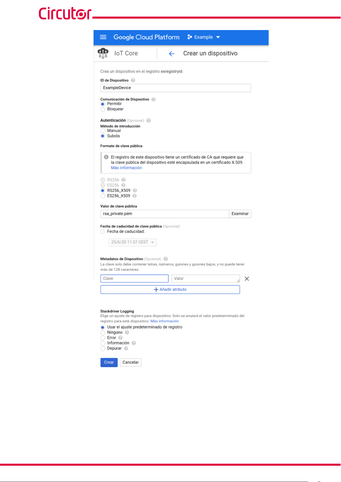
8.- Creating a device.
8.1.- In the IoT Core screen, click on Crear dispositivo (Create device).
Figure 68: Google screen: Devices.
8.2.- To create a new device, fill in the following sections:
ID de Dispositivo: Make a note of this, as it needs to be used in the line-EDS-Cloud configuration.
Comunicación de Dispositivo: Select Permitir.
Autenticación:
● In Método de introducción (Introduction method), select Subida.
● In Formato de clave pública (Public key format), select RS256.
● In Valor de clave pública (Public key value), upload the file rsa_cert.pem generated
previously.
Stackdriver Logging: Select Usar el ajuste predeterminado de registro (Use the default registry
setting).
Finish creating the device by clicking Crear.
Instruction Manual
57
line-EDS-Cloud
58
Figure 69: Google screen: Creating a device.
9.- Enter all the data obtained from the Google Cloud IoT Core platform into the device configuration
website.
10.- Once the data export to the Google Cloud IoT Core platform has been configured, the readings for
the values from the devices linked to the line-EDS-Cloud will be shown on the platform.
Instruction Manual

line-EDS-Cloud
To do this, in the navigation menu, go to Big data → IoT Core and select the registry and the device
created.
The dates of the last data sets received are displayed on the screen.
Figure 70: Google screen: Device.
Instruction Manual
59

CIRCUTOR, SA
Vial Sant Jordi, s/n
08232 - Viladecavalls (Barcelona)
Tel: (+34) 93 745 29 00 - Fax: (+34) 93 745 29 14
www.circutor.es central@circutor.com
 Loading...