


Power analyser
line-CVM-D32
INSTRUCTION MANUAL
(M237B01-03-19A)

line-CVM-D32
2
Instruction Manual
line-CVM-D32
SAFETY PRECAUTIONS
Follow the warnings described in this manual with the symbols shown below.
DANGER
Warns of a risk, which could result in personal injury or material damage.
ATTENTION
Indicatesthatspecialattentionshouldbepaidtoaspecicpoint.
If you must handle the unit for its installation, start-up or maintenance, the following
should be taken into consideration:
Incorrect handling or installation of the unit may result in injury to personnel as well as damage
to the unit. In particular, handling with voltages applied may result in electric shock, which may
cause death or serious injury to personnel. Defective installation or maintenance may also
leadtotheriskofre.
Read the manual carefully prior to connecting the unit. Follow all installation and maintenance
instructions throughout the unit’s working life. Pay special attention to the installation standards of the National Electrical Code.
Refer to the instruction manual before using the unit
In this manual, if the instructions marked with this symbol are not respected or carried out correctly, it can
result in injury or damage to the unit and /or installations.
CIRCUTOR,SAreservestherighttomodifyfeaturesortheproductmanualwithoutpriornotication.
DISCLAIMER
CIRCUTOR, SAreservestherighttomakemodicationstothedeviceortheunitspecica-
tions set out in this instruction manual without prior notice.
CIRCUTOR, SA on its web site, supplies its customers with the latest versions of the device
specicationsandthemostupdatedmanuals.
www.circutor.com
CIRCUTOR, recommends using the original cables and accessories that are
supplied with the device.
Instruction Manual
3

line-CVM-D32
CONTENTS
SAFETY PRECAUTIONS ���������������������������������������������������������������������������������������������������������������������������������������3
DISCLAIMER ���������������������������������������������������������������������������������������������������������������������������������������������������������� 3
CONTENTS ������������������������������������������������������������������������������������������������������������������������������������������������������������� 4
REVISION LOG ������������������������������������������������������������������������������������������������������������������������������������������������������� 6
SYMBOLS ��������������������������������������������������������������������������������������������������������������������������������������������������������������� 6
1�- VERIFICATION UPON RECEPTION ����������������������������������������������������������������������������������������������������������������� 7
2�- PRODUCT DESCRIPTION �������������������������������������������������������������������������������������������������������������������������������� 7
3�- INSTALLATION OF THE DEVICE ��������������������������������������������������������������������������������������������������������������������� 9
3�1�- PRELIMINARY RECOMMENDATIONS ����������������������������������������������������������������������������������������������������9
3�2�- INSTALLATION ��������������������������������������������������������������������������������������������������������������������������������������� 10
3�3�- 72 x 72 mm PANEL ADAPTER ��������������������������������������������������������������������������������������������������������������� 10
3�4�- DEVICE TERMINALS ������������������������������������������������������������������������������������������������������������������������������ 11
3�5�- EXPANSION WITH OTHER DEVICES ���������������������������������������������������������������������������������������������������� 12
3�5�1�- Line-M-EXT-PS POWER ADAPTER ������������������������������������������������������������������������������������������������ 12
3�5�2�- INSTALLATION ��������������������������������������������������������������������������������������������������������������������������������� 13
3�6�- CONNECTION DIAGRAMS �������������������������������������������������������������������������������������������������������������������� 15
3�6�1�- 3-PHASE MAINS MEASUREMENT WITH 4-WIRE CONNECTION ������������������������������������������������ 15
3�6�2�- 3-PHASE MAINS MEASUREMENT WITH 3-WIRE CONNECTION ������������������������������������������������ 17
3�6�3�- 3-PHASE MAINS MEASUREMENT WITH 3-WIRE CONNECTION AND TRANSFORMERS WITH
ARON CONNECTION���������������������������������������������������������������������������������������������������������������������������������� 19
3�6�4�- 2-PHASE MAINS MEASUREMENT WITH 3-WIRE CONNECTION ������������������������������������������������ 20
3�6�5�- SINGLE PHASE MAINS MEASUREMENT WITH 2-WIRE PHASE-TO-PHASE CONNECTION ��� 21
3�6�6�- SINGLE PHASE MAINS MEASUREMENT WITH 2-WIRE PHASE-TO-NEUTRAL
CONNECTION ��������������������������������������������������������������������������������������������������������������������������������������������� 22
4�- OPERATION ��������������������������������������������������������������������������������������������������������������������������������������������������� 23
4�1�- MEASUREMENT PARAMETERS ����������������������������������������������������������������������������������������������������������� 24
4�1�1�- QUALITY PARAMETERS ����������������������������������������������������������������������������������������������������������������� 26
4�2� - LED INDICATORS ���������������������������������������������������������������������������������������������������������������������������������� 27
4�3�- DISPLAY �������������������������������������������������������������������������������������������������������������������������������������������������� 28
4�4�- KEYBOARD FUNCTIONS ����������������������������������������������������������������������������������������������������������������������� 28
4�5�- DIGITAL OUTPUTS �������������������������������������������������������������������������������������������������������������������������������� 29
5�- DISPLAY ���������������������������������������������������������������������������������������������������������������������������������������������������������� 30
5�1�- INSTANTANEOUS VALUE MENU ����������������������������������������������������������������������������������������������������������31
5�1�1�- MAXIMUM AND MINIMUM VALUES ������������������������������������������������������������������������������������������������ 32
5�2�- ENERGY MENU���������������������������������������������������������������������������������������������������������������������������������������33
5�3�- MAXIMUM DEMAND MENU ������������������������������������������������������������������������������������������������������������������� 35
5�3�1�- MAXIMUM VALUES �������������������������������������������������������������������������������������������������������������������������� 36
5�4�- QUALITY PARAMETERS MENU ������������������������������������������������������������������������������������������������������������ 37
5�5�- VOLTAGE HARMONIC MENU ���������������������������������������������������������������������������������������������������������������� 38
5�6�- CURRENT HARMONIC DISPLAY ����������������������������������������������������������������������������������������������������������� 38
5�7�- METER MENU ����������������������������������������������������������������������������������������������������������������������������������������� 39
5�8�- INFORMATION MENU����������������������������������������������������������������������������������������������������������������������������� 41
5�9�- INPUT / OUTPUT MENU ������������������������������������������������������������������������������������������������������������������������� 42
6�- CONFIGURATION ������������������������������������������������������������������������������������������������������������������������������������������� 43
6�1�- MEASUREMENT CONFIGURATION ������������������������������������������������������������������������������������������������������ 44
6�1�1�- PRIMARY AND SECONDARY VOLTAGE ����������������������������������������������������������������������������������������44
6�1�2�- PRIMARY AND SECONDARY CURRENT ���������������������������������������������������������������������������������������� 45
6�1�3�- QUADRANTS AND MEASUREMENT CONVENTION ���������������������������������������������������������������������46
6�1�4�- INSTALLATION TYPE ����������������������������������������������������������������������������������������������������������������������� 46
6�1�5�- CALCULATION PERIODS ���������������������������������������������������������������������������������������������������������������� 47
6�1�6�- CLEAR MAXIMUMS, MINIMUMS AND MAXIMUM DEMAND ��������������������������������������������������������� 48
6�1�7�- CLEAR ENERGIES AND DELETE ALL�������������������������������������������������������������������������������������������� 48
6�1�8�- HARMONICS AND CURRENCY DISPLAY ��������������������������������������������������������������������������������������� 49
6�1�9�- DISPLAY BACKLIGHT AND PASSWORD ���������������������������������������������������������������������������������������49
6�2�- QUALITY PARAMETER CONFIGURATION ������������������������������������������������������������������������������������������� 50
6�2�1�- NOMINAL VOLTAGE AND FREQUENCY ����������������������������������������������������������������������������������������50
6�2�2�- OVERVOLTAGE AND GAPS ������������������������������������������������������������������������������������������������������������ 51
6�2�3�- INTERRUPTION AND HYSTERESIS VALUE ���������������������������������������������������������������������������������� 51
6�2�4�- CLEAR QUALITY PARAMETERS ���������������������������������������������������������������������������������������������������� 52
4
Instruction Manual

line-CVM-D32
6�3�- DEVICE CLOCK SETTING ���������������������������������������������������������������������������������������������������������������������53
6�3�1�- DATE FORMAT���������������������������������������������������������������������������������������������������������������������������������� 53
6�3�2�- DATE AND TIME ������������������������������������������������������������������������������������������������������������������������������� 53
6�4�- COMMUNICATIONS CONFIGURATION ������������������������������������������������������������������������������������������������� 54
6�4�1�- PERIPHERAL NUMBER AND TRANSMISSION SPEED �����������������������������������������������������������������54
6�4�2�- DATA FORMAT AND MEASURE TIME ��������������������������������������������������������������������������������������������54
6�5�- RATIO CONFIGURATION ����������������������������������������������������������������������������������������������������������������������� 55
6�5�1�- CO2 EMISSIONS IN CONSUMPTION, TARIFFS 1 AND 2 ���������������������������������������������������������������55
6�5�2�- CO2 EMISSIONS IN CONSUMPTION, TARIFFS 3 AND 4 ���������������������������������������������������������������56
6�5�3�- COST OF CONSUMED ENERGY IN CONSUMPTION, TARIFFS 1 AND 2 ������������������������������������� 57
6�5�4�- ENERGY COST IN CONSUMPTION, TARIFFS 3 AND 4 ����������������������������������������������������������������� 57
6�5�5�- CO2 EMISSIONS IN GENERATION, TARIFFS 1 AND 2 ������������������������������������������������������������������� 58
6�5�6�- CO2 EMISSIONS IN GENERATION, TARIFFS 3 AND 4 ������������������������������������������������������������������� 58
6�5�7�- ENERGY COST IN GENERATION, TARIFFS 1 AND 2 ��������������������������������������������������������������������59
6�5�8�- ENERGY COST IN GENERATION, TARIFFS 3 AND 4 ��������������������������������������������������������������������60
6�6�- CONFIGURATION OF DIGITAL OUTPUTS 1 AND 2 �����������������������������������������������������������������������������61
6�6�1�- VARIABLE ����������������������������������������������������������������������������������������������������������������������������������������� 61
6�6�2�- MAXIMUM AND MINIMUM VALUE����������������������������������������������������������������������������������������������������65
6�6�3�- CONNECTION AND DISCONNECTION DELAY ������������������������������������������������������������������������������65
6�6�4�- HYSTERESIS AND STATUS OF CONTACTS ���������������������������������������������������������������������������������� 66
6�6�5�- LATCH �����������������������������������������������������������������������������������������������������������������������������������������������66
6�6�6�- ENERGY PER PULSE AND CONTACT STATUS ����������������������������������������������������������������������������� 67
6�6�7�- PULSE �����������������������������������������������������������������������������������������������������������������������������������������������68
6�6�8�- DIGITAL OUTPUT MANUAL OPERATION ���������������������������������������������������������������������������������������69
7�- RS-485 COMMUNICATIONS ��������������������������������������������������������������������������������������������������������������������������� 70
7�1�- CONNECTIONS ��������������������������������������������������������������������������������������������������������������������������������������� 70
7�2�- MODBUS PROTOCOL ����������������������������������������������������������������������������������������������������������������������������71
7�2�1�- MODBUS QUERY EXAMPLE ����������������������������������������������������������������������������������������������������������� 71
7�3�- MODBUS MEMORY MAP ����������������������������������������������������������������������������������������������������������������������� 72
7�3�1�- MEASUREMENT VARIABLES ��������������������������������������������������������������������������������������������������������� 72
7�3�2 �- ENERGY VARIABLES����������������������������������������������������������������������������������������������������������������������79
7�3�3�- MAXIMUM DEMAND VARIABLES ��������������������������������������������������������������������������������������������������� 83
7�3�4�- VOLTAGE AND CURRENT HARMONICS� ��������������������������������������������������������������������������������������� 87
7�3�5�- COST VARIABLES ����������������������������������������������������������������������������������������������������������������������������89
7�3�6�- ANGLE VARIABLES �������������������������������������������������������������������������������������������������������������������������90
7�3�7�- QUALITY EVENT AND DISTURBANCE COUNTERS ���������������������������������������������������������������������90
7�3�8�- OTHER DEVICE PARAMETERS ������������������������������������������������������������������������������������������������������ 90
7�3�9�- DIGITAL OUTPUTS �������������������������������������������������������������������������������������������������������������������������� 91
7�3�10�- DEVICE CONFIGURATION VARIABLES ���������������������������������������������������������������������������������������91
7�3�11�- CLEAR PARAMETERS �������������������������������������������������������������������������������������������������������������������95
8�- TECHNICAL FEATURES ��������������������������������������������������������������������������������������������������������������������������������96
9�- MAINTENANCE AND TECHNICAL SERVICE ������������������������������������������������������������������������������������������������ 99
10 �- GUARANTEE ������������������������������������������������������������������������������������������������������������������������������������������������99
11�- CE CERTIFICATE ����������������������������������������������������������������������������������������������������������������������������������������100
ANNEX A�- CONFIGURATION MENU ����������������������������������������������������������������������������������������������������������������103
Instruction Manual
5
REVISION LOG
Date Revision Description
03/20 M237B01-03-19A First Version
line-CVM-D32
Table 1: Revision log�
SYMBOLS
Symbol Description
~
Table 2: Symbols�
In accordance with the relevant European directive.
In accordance with the CMiM directive.
Device covered by European Directive 2012/19/EC. At the end of its useful life, do not
leave the device in a household refuse bin. Follow local regulations on electronic equipment recycling.
Direct current.
Alternating current.
Note: The images on the devices are for illustrative use only and may differ from the original
device.
6
Instruction Manual

line-CVM-D32
1�- VERIFICATION UPON RECEPTION
Upon reception of the device check the following points:
a)Thedevicemeetsthespecicationsdescribedinyourorder.
b) The device has not suffered any damage during transport.
c) Perform an external visual inspection of the device prior to switching it on.
d) Check that it has been delivered with the following:
- An installation guide
If any problem is noticed upon reception, immediately contact the transport
company and/or CIRCUTOR's after-sales service�
2�- PRODUCT DESCRIPTION
The line-CVM-D32 is a device that measures, calculates and displays the main electrical
parameters in single-phase mains, two-phase mains with and without neutral, and balanced
three-phase mains with ARON measurement or unbalanced. Measurement is performed at true
RMS value, using three AC voltage inputs and three current inputs.
Currentmeasurementis performed indirectly through /5A,/1AtransformersorefcientMC1
and MC3 series transformers (/0.250A).
The device features:
- Display to display parameters.
- 3 keys to browse through the different screens and program the equipment.
- 2 digital transistor outputs.
- RS-485 communications, with MODBUS RTU© protocol.
Instruction Manual
7
The line-CVM-D32 can be expanded with the following expansion modules:
line-M-4IO-R, expansion module with 4 digital inputs and 4 relay outputs.
line-M-4IO-T expansion module with 4 digital inputs and 4 transistor outputs.
line-M-4IO-A, expansion module with 4 analogue inputs and outputs.
line-M-4IO-RV, expansion module with 4 digital inputs (230 V~) and 4 relay outputs.
line-M-EXT-PS, power adapter module.
line-CVM-D32
8
Instruction Manual

line-CVM-D32
3�- INSTALLATION OF THE DEVICE
3.1.- PRELIMINARY RECOMMENDATIONS
In order to use the device safely, personnel operating it must follow the safety
measures that comply with the standards of the country where it is to be installed;
operators must wear the required personal protective equipment (rubber gloves,
approvedfacialprotectionandame-resistant clothing)topreventinjuriesfrom
electric shock or arcs caused by exposure to current-carrying conductors, and
they must heed the various warnings indicated in this instruction manual.
The line-CVM-D32 devicemustbeinstalledbyauthorised,qualiedpersonnel.
The power supply plug must be disconnected and measurement systems switched off before
handling, altering the connections or replacing the device. It is dangerous to handle the device
while it is powered.
Cables must always be kept in perfect condition to avoid accidents or injury to personnel or
installations.
Restricttheoperationofthedevicetothespeciedmeasurementcategory,voltageorcurrent
values.
The manufacturer of the device is not responsible for any damage resulting from failure by the
user or installer to heed the warnings and/or recommendations set out in this manual, nor for
damage resulting from the use of non-original products or accessories or those made by other
manufacturers.
Do not use the device to take any measurements if an anomaly or malfunction is detected.
Check the surrounding environment before starting to take measurements. Do not take any
measurements in hazardous or explosive environments.
Before carrying out maintenance, repair or handling of any of the device's connections, the device must be disconnected from all power sources, both from the
device's own power supply and the measurement's.
Contact the after-sales service if you detect that the device is not working properly.
Instruction Manual
9

line-CVM-D32
3.2.- INSTALLATION
When the device is on, its terminals, opening covers or removing elements may
expose the user to parts that are hazardous to touch. Do not use the device
until it is fully installed.
The device must be installed inside a medium or low voltage electric panel or enclosure, with
DIN rail mounting (IEC 60715).
The minimum recommended distance between rails to install the line-CVM-D32 devices is 150
mm.
The device must be connected to a power supply circuit protected by gl type (IEC 269) or M
typefuses,between0.5and2A.Itmustbettedwithacircuit-breakerorequivalentdeviceto
disconnect the device from the mains supply.
The power supply and voltage measurement circuits must be connected with a 1mm² minimum
cross-section cable.
The current transformer's secondary line must have a 2.5 mm2 minimum cross-section.
The insulation temperature of the cables connected to the device must be at least 62°C.
3.3.- 72 x 72 mm PANEL ADAPTER
Note: The 72 x 72 mm panel adapter is a separately sold accessory.
CIRCUTOR has a panel adapter for the line-CVM-D32 devices and their expansion modules
for their installation in 72 x 72 mm panels.
Figure 1 illustrates how the panel adapter connects to a line-CVM-D32.
Before installing the adapter, the device must be disconnected from all power
and measurement supplies.
10
Figure 1: Installation of the panel adapter�
Instruction Manual

line-CVM-D32
Protection degree IP40
Casing Self-extinguishing V0 plastic
Table 3: Technical characteristics of the Panel Adapter�
Technical Specications
68 mm
68 mm
Figure 2: Cut in the panel�
3.4.- DEVICE TERMINALS
11
9
Figure 3: Line-CVM-D32 terminals: Upper - Lower�
1: U1, voltage input L1 16: s2, current input L2
3: U2, voltage input L2 17: s1, current input L3
5: U3, voltage input L3 18: s2, current input L3
6: N, neutral input 19: C, common digital outputs
9: A1 ~/+, Auxiliary power supply 20: 2, digital output 2
11: A2 ~/-, Auxiliary power supply 21: 1, digital output 1
13: s1, current input L1 22: B-, RS-485
14: s2, current input L1 23: S, GND for RS-485
15: s1, current input L2 24: A+, RS-485
1
3
5
6
Table 4: List of line-CVM-D32 terminals�
13
14
15
16
17
18
Device terminals
24
23
22
21
20
19
Instruction Manual
11
line-CVM-D32
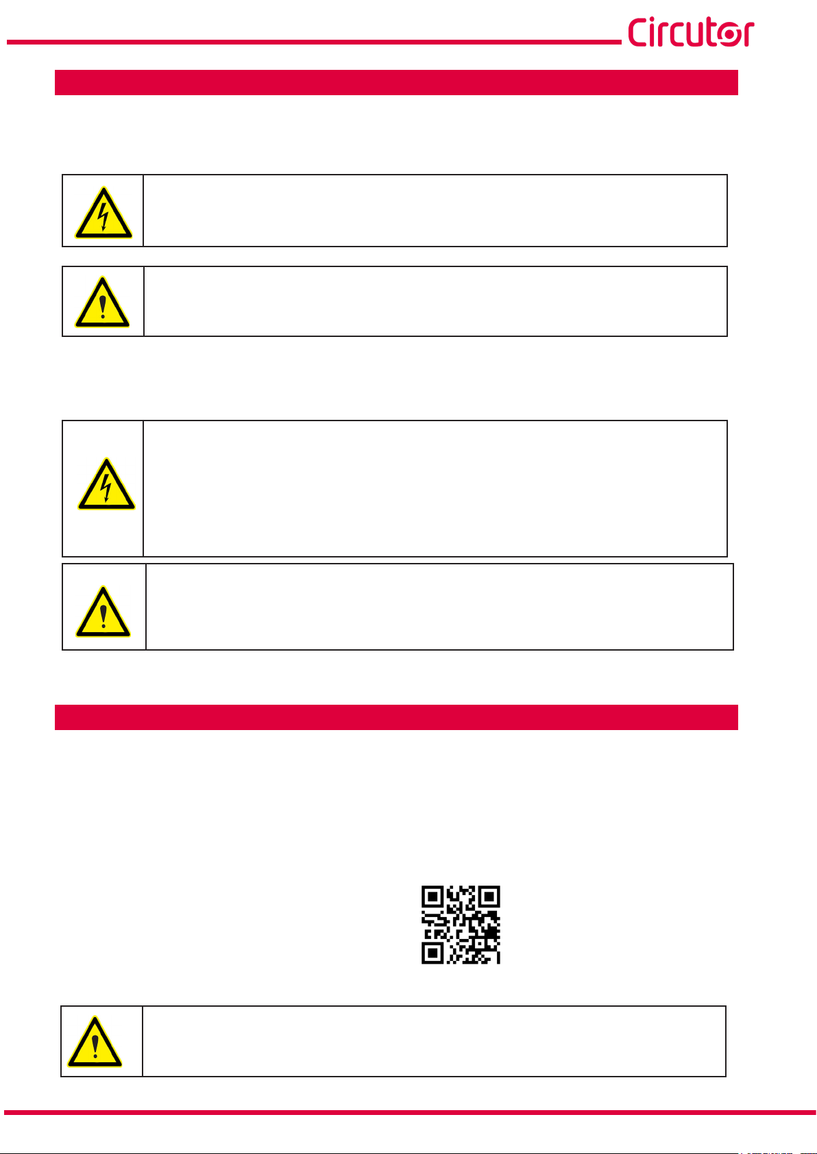
3.5.- EXPANSION WITH OTHER DEVICES
The line-CVM-D32 devices can be expanded with other devices in the Line range, and with the
line-EDS and line-M expansion modules .
The line-EDS and line-CVM devices enable up to 2 expansion modules to be directly connect-
ed to their right-hand side
(1)
.
line-EDS line-M line-M
line-CVM
line-M line-M
Figure 4: Line-EDS and line CVM expansion module connection�
(1)
Expansion module types: line-M-4IO-R, line-M-4IO-T, line-M-4IO-RV and line-M-4IO-A�
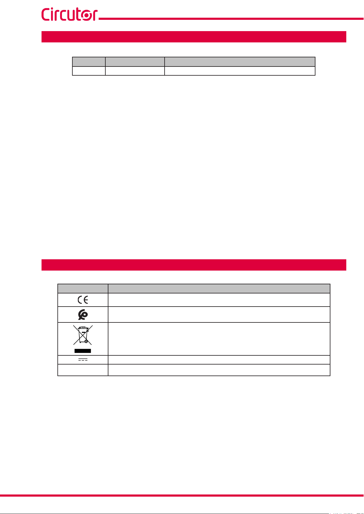
In installations with line-EDS devices, a total of up to seven devices may be connected to their
right-hand side.
line-EDS line-M line-M
Figure 5: Typical installation of a line-EDS with 7 devices�
line-CVM
line-M line-M
line-CVM line-CVM
Note: An installation may only be tted with one line-EDS device.
Note: In installations without line-EDS devices, only one line-CVM device may ne installed.
Note: All line-EDS and line-CVM devices must be connected to the auxiliary power supply.
12
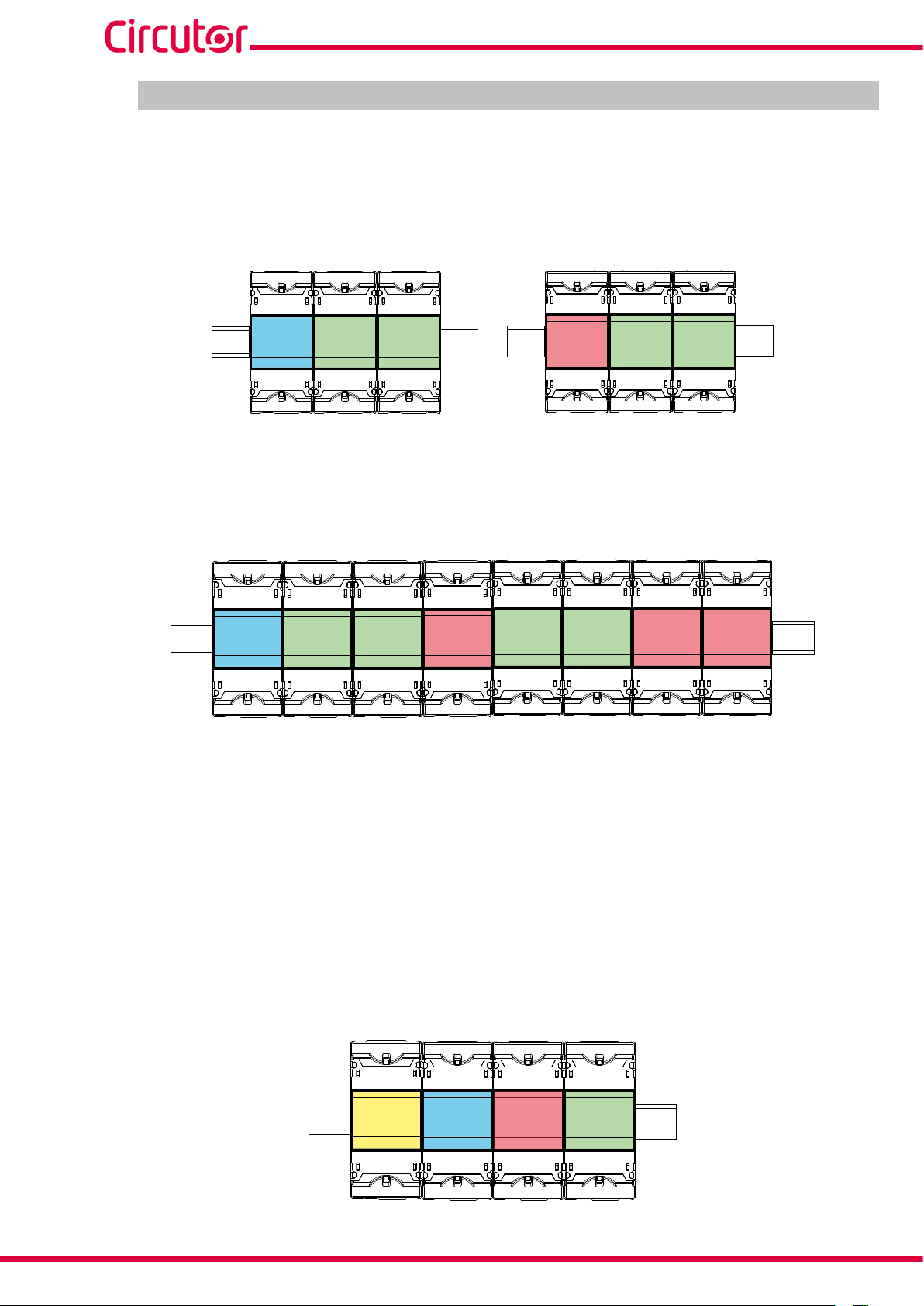
3�5�1�- Line-M-EXT-PS POWER ADAPTER
Line-M-EXT-PS is a power adapter belonging to the Line family of devices. The module con-
nects to the left-hand side of the devices to be fed. It can supply up to 10 VA, allowing it to
power a limited number of devices.
The maximum set it can supply is: 1 line-EDS + 1 line-CVM + 1 line-M (Figure 6).
line-M-EXT-PS
Figure 6: Maximum set a line-M-EXT-PS can supply�
line-EDS line-M
line-CVM
Instruction Manual

line-CVM-D32
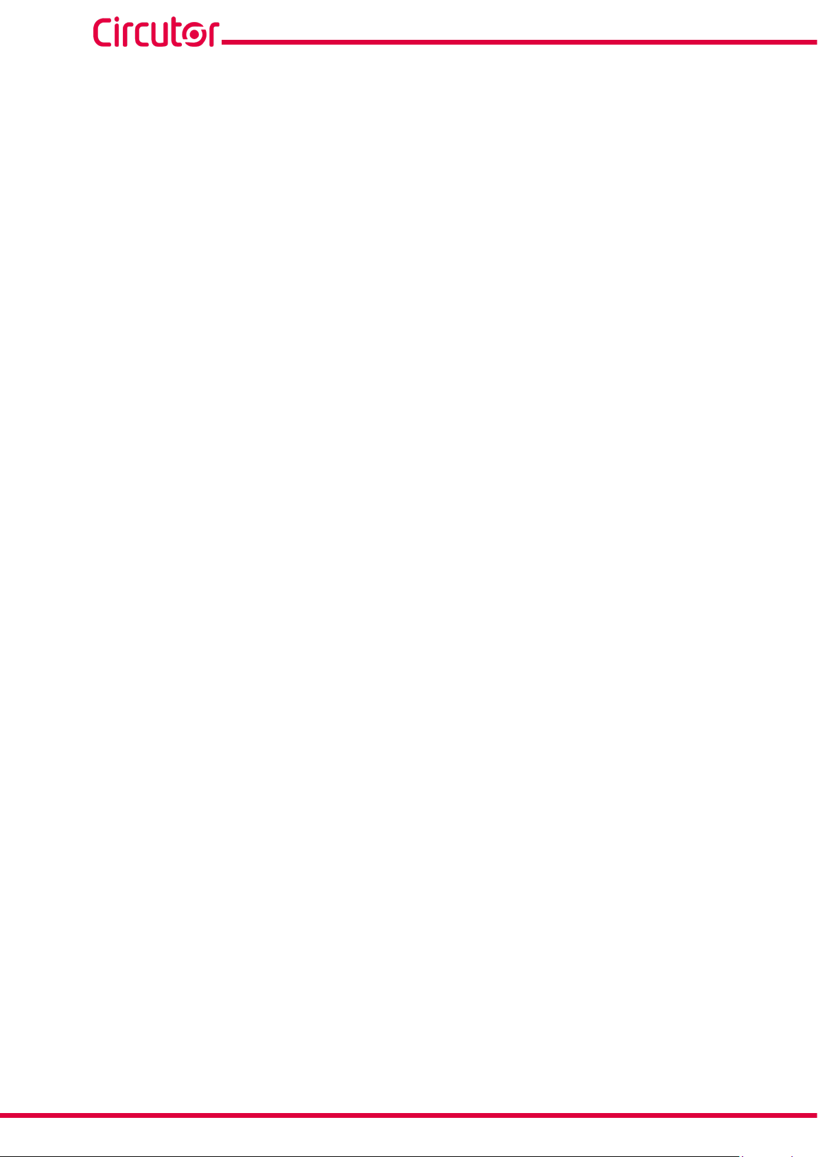
Multiple line-M-EXT-PS devices can be connected to supply sets with power above 10VA. Each
line-M-EXT-PS will power the devices connected to its right-hand side (Figure 7).
line-M-EXT-PS
line-EDS line-M line-M
Figure 7: Multiple line-M-EXT-PS connection�
line-M-EXT-PS
line-CVM
line-M line-M
line-M-EXT-PS
line-CVM line-CVM
Note: None of the line-EDS or line-CVM devices should be connected to the auxiliary power
supply.
3�5�2�- INSTALLATION
Before installing a new device, it must be disconnected from all power supplies.
The correct steps to connect the devices are:
1�-Usingaatheadscrewdriver,removetheexpansionconnector'sprotectivecoverslocated
on the side of the devices, (Figure 8).
line-CVM-D32
Figure 8: Installation step 1�
2�- Insert the expansion connector and fastening clips into one of the devices (Figure 9).
Instruction Manual
13

line-CVM-D32
line-CVM-D32
Figure 9: Installation step 2�
3 �- Connect both devices and fasten them by pushing the front clips down (Figure 10).
line-CVM-D32
Figure 10: Installation step 3�
For correct installation of all devices, please refer to the instruction manual for
the different models:
M231B01-03-xxx : Instruction Manual for line-EDS devices.
M239B01-03-xxx : Instruction Manual for line-M expansion modules.
14
Instruction Manual

line-CVM-D32
3.6.- CONNECTION DIAGRAMS
3�6�1�- 3-PHASE MAINS MEASUREMENT WITH 4-WIRE CONNECTION
Installation type: 4W-3Ph
N
L3
V
V
L2
L1
V
6
5
3
1
Alimentación Auxiliar
Power Supply
9
11
~ / + A1
~ / - A2
13
14
15
16
17
18
S1
S2
S1 S2
P2
P1
P2
P1
P1
S1
S2
P2
L1
L2
L3
S1
S2
S1
S2
S1
S2
VL1 VL2 VL3
VL1 VL2
b
a
A B
N
CARGA / LOAD
a
b
A B
VL3 N
Figure 11: 3-phase mains measurement with 4-wire connection: Current transformers���/5A , ���/1A o MC1 (���/0�250A)�
Note: Do not connect the MC current transformers to earth.
Instruction Manual
15

line-CVM-D32
N
L3
V
V
L2
L1
V
6
5
3
1
Alimentación Auxiliar
Power Supply
9
11
~ / +
~ / -
A1
A2
Grey/Pink
13
S1
14
S2
S1
S2
S1
S2
15
16
17
18
Green/White
Red/Blue
Brown/Green
VL1 VL2 VL3
b
a
A B
a
b
A B
VL1 VL2
VL3 N
L1
L2
L3
N
CARGA / LOAD
2P1 1P1
3P1
2P2 1P2
3P2
Figure 12: 3-phase mains measurement with 4-wire connection: MC3 series current transformers (���/0�250A)�
16
Instruction Manual

line-CVM-D32
3�6�2�- 3-PHASE MAINS MEASUREMENT WITH 3-WIRE CONNECTION
Installation type: 3W-3Ph
V
L3
V
L2
L1
V
Alimentación Auxiliar
5
3
1
Power Supply
9
11
~ / +
~ / -
A1
A2
L1
L2
L3
VL1 VL2 VL3
b
a
A
B
CARGA / LOAD
a
b
A B
VL1 VL2
S1
S2
S1
S2
VL3
S1
S2
13
14
15
16
17
18
S1
S2
S1 S2
P2
P1
P2
P1
P1
S1
S2
P2
Figure 13: 3-phase mains measurement with 3-wire connection: Current transformers���/5A , ���/1A o MC1 (���/0�250A)�
Note: Do not connect the MC current transformers to earth.
Instruction Manual
17

line-CVM-D32
V
L3
V
L2
L1
V
5
3
1
Alimentación Auxiliar
Power Supply
9
11
~ / +
~ / -
A1
A2
S1
S2
S1
S2
S1
S2
13
14
15
16
17
18
Grey/Pink
Green/White
Red/Blue
Brown/Green
VL1 VL2 VL3
VL1 VL2
b
a
A
B
a
b
A B
VL3
L1
L2
L3
2P1 1P1
3P1
2P2 1P2
3P2
CARGA / LOAD
Figure 14: 3-phase mains measurement with 3-wire connection: MC3 series current transformers (���/0�250A)�
18
Instruction Manual

line-CVM-D32
3�6�3�- 3-PHASE MAINS MEASUREMENT WITH 3-WIRE CONNECTION AND TRANSFORMERS WITH ARON CONNECTION
Installation type: ARON
V
L3
L2
V
L1
V
S1
S2
S1
S2
S1
S2
Alimentación Auxiliar
5
3
1
13
14
15
16
17
18
Power Supply
9
11
~ / +
A1
A2~ / -
VL1 VL2 VL3
L1
L2
L3
b
a
A
B
CARGA / LOAD
a
b
A B
VL1 VL2
VL3
P1
S1
S2
P2
P1
S1
S2
P2
Figure 15: 3-phase mains measurement with 3-wire connection and transformers with ARON connection
Note: Do not connect the MC current transformers to earth.
Instruction Manual
19

3�6�4�- 2-PHASE MAINS MEASUREMENT WITH 3-WIRE CONNECTION
N
Installation type: 3W-2Ph
6
Alimentación Auxiliar
L2
V
L1
V
3
1
Power Supply
9
11
~ / +
~ / -
line-CVM-D32
A1
A2
L1
L2
13
S1
14
S2
15
S1
16
S2
S1
S2
VL1 N VL2
VL1 VL2
a
b
a
A
B
N
CARGA / LOAD
b
A B
N
S1 S2
P1
S1
S2
P2
P1
P2
20
Figure 16: 2-phase mains measurement with 3-wire connection
Note: Do not connect the MC current transformers to earth.
Instruction Manual

line-CVM-D32
3�6�5�- SINGLE PHASE MAINS MEASUREMENT WITH 2-WIRE PHASE-TO-PHASE CONNECTION
Installation type: 2W-2Ph
Alimentación Auxiliar
1
Power Supply
9
11
~ / +
~ / -
A1
A2
L2
V
L1
V
3
S1
13
14
S2
S1
S2
S1
S2
VL1 VL2
VL1 VL2
a
b
A B
L1
L2
CARGA / LOAD
Figure 17: Single phase mains measurement with 2-wire phase-to-phase connection
Note: Do not connect the MC current transformers to earth.
P1
S1
S2
P2
Instruction Manual
21

line-CVM-D32
3�6�6�- SINGLE PHASE MAINS MEASUREMENT WITH 2-WIRE PHASE-TO-NEUTRAL
CONNECTION
Installation type: 2W-1Ph
N
L1
V
6
Alimentación Auxiliar
Power Supply
9
1
11
~ / + A1
A2
~ / -
13
S1
14
S2
S1
S2
S1
S2
VL1 N
VL1 N
a b
A B
L1
N
CARGA / LOAD
Figure 18: Single phase mains measurement with 2-wire phase-to-neutral connection
Note: Do not connect the MC current transformers to earth.
P1
S1
S2
P2
22
Instruction Manual

line-CVM-D32
0º
90º
180º
-90º
Capacitive
Capacitive
Inductive
Inductive
Generation
Power
Consumption
Power
Single-phaseThree-phase
Single-phase
Single-phase
Single-phase
Three-phase
Three-phase
Three-phase
k
k
k
k
k
k
k
k
k
k
k
k
k
k
k
k
k
k
k
k
4�- OPERATION
The line-CVM-D32 device is a power analyser for all four quadrants (consumption and generation).
The device can operate under three different measurement conventions:
Measurement convention CIRCUTOR.
Measurement convention IEC.
Measurement convention IEEE.
Themeasurementconventionisconguredusingthecongurationmenu, see “6.1.3.- QUAD-
RANTS AND MEASUREMENT CONVENTION"�
Measurement convention CIRCUTOR :
Measurement convention IEC:
Figure 19: Measurement convention CIRCUTOR�
Operation in the 4 quadrants (Q1, Q2, Q3, Q4)
Q
P < 0 Q > 0 PF < 0
Capacitive
Inductive
P < 0 Q < 0 PF < 0 P > 0 Q < 0 PF > 0
Q3
P > 0 Q > 0 PF > 0
Inductive
Capacitive
Figure 20: Measurement convention IEC�
Q1Q2
P
Q4
cos φ values in the receiver operating mode (Q1,Q4)
0 +
0 +
Q1
cos φ > 0
+ 1
+ 1
cos φ > 0
Q4
Instruction Manual
23

Measurement convention IEEE:
line-CVM-D32
Operation in the 4 quadrants (Q1, Q2, Q3, Q4)
Q
P < 0 Q > 0 PF > 0
Capacitive
Inductive
P < 0 Q < 0 PF < 0 P > 0 Q < 0 PF > 0
Q3
4.1.- MEASUREMENT PARAMETERS
P > 0 Q > 0 PF < 0
Figure 21: Measurement convention IEEE�
Q1Q2
Inductive
Capacitive
Q4
cos φ values in the receiver operating mode (Q1,Q4)
0 -
P
0 +
The device measures and displays different types of parameters:
Q1
cos φ < 0
- 1
+ 1
cos φ > 0
Q4
Electrical parameters,
Quality parameters, such as overvoltages, dips and interruptions according to EN50160.
Table 5: Line-CVM-D32 measurement parameters
Parameter Units
Phases
L1-L2-L3
Phase-Neutral voltage V
Phase-to-Phase Voltage V
Current A
Frequency Hz -
Active Power W
Consumed Active Power
Generated Active Power
(2)
(2)
W
W
Apparent Power VA
Reactive Power var
Consumed Reactive Power
Generated Reactive Power
(2)
(2)
var
var
Inductive Reactive Power varL
Consumed Inductive Reactive Power
Generated Inductive Reactive Power
(2)
(2)
varL
varL
Capacitive Reactive Power varC
Consumed Capacitive Reactive Power
Generated Capacitive Reactive Power
(2)
(2)
varC
varC
Power factor PF
Consumed Power Factor
(2)
PF
(2)
Total
III
Value
Max�
Value
Min�
24
Instruction Manual

line-CVM-D32
Table 5 (Continued): Line-CVM-D32 measurement parameters�
Parameter Units
Generated Power Factor
(2)
Cosφ φ
CosφConsumed
CosφGenerated
(2)
(2)
Voltage THD %
Current THD %
Harmonic Voltage Decomposition
(up to 40th harmonic)
Harmonic Current Decomposition
(up to 40th harmonic)
Consumed Active Energy
Generated Active Energy
Consumed Active Energy Tariffs 1-2-3-4
Generated Active Energy Tariffs 1-2-3-4
Consumed Inductive Reactive Energy
Generated Inductive Reactive Energy
Consumed Inductive Reactive Energy Tariffs 1-2-3-4
Generated Inductive Reactive Energy Tariffs 1-2-3-4
Consumed Capacitive Reactive Energy
Generated Capacitive Reactive Energy
Consumed Capacitive Reactive Energy Tariffs 1-23-4
Generated Capacitive Reactive Energy Tariffs 1-23-4
Consumed Reactive Energy
Generated Reactive Energy
Consumed Reactive Energy Tariffs 1-2-3-4
Generated Reactive Energy Tariffs 1-2-3-4
Consumed Apparent Energy
Generated Apparent energy
Consumed Apparent Energy Tariffs 1-2-3-4
Generated Apparent Energy Tariffs 1-2-3-4
(2)
(2)
V - %
A - %
kWh
kWh
kWh
kWh
kvarLh
kvarLh
kvarLh
kvarLh
kvarCh
kvarCh
kvarCh
kvarCh
(2)
(2)
(2)
(2)
kvarh
kvarh
kvarh
kvarh
kVAh
kVAh
kVAh
kVAh
Maximum Current Demand Tariffs 1-2-3-4
Maximum Active Power Demand Tariffs 1-2-3-4
Maximum Apparent Power Demand Tariffs 1-2-3-4
Maximum Inductive Reactive Power Demand Tariffs
1-2-3-4
(2)
Maximum Capacitive Reactive Power Demand Tariffs 1-2-3-4
(2)
Maximum Reactive Power Demand Tariffs 1-2-3-4
Angleθ
AngleθV-I
Overvoltage meter
(2)
(2)
(2)
varL
varC
(2)
PF
φ
φ
A
W
VA
var
º
º
Phases
L1-L2-L3
Total
III
Value
Max�
(2)
(2)
(2)
(2)
(2)
(2)
(2)
(2)
-
-
- - -
- - -
- -
- -
- -
- -
- -
- -
- -
- -
- -
- -
- -
- -
- -
- -
- -
- -
- -
- -
- -
- -
- - -
- - -
- - -
Value
Mini�
(2)
(2)
(2)
(2)
-
-
-
-
-
-
Instruction Manual
25

Table 5 (Continued): Line-CVM-D32 measurement parameters�
Parameter Units
Gap meter
(2)
Voltage interruption meter
(2)
Phases
L1-L2-L3
Parameter Units T1-T2-T3-T4 Total
Nº of hours of active energy consumed hours
Nº of hours of Active Energy generated hours
Cost of consumed Active Energy EUR
Cost of generated Active Energy EUR
CO2 emissions from consumed Active Energy kgCO
CO2 emissions from generated Active Energy kgCO
(2)
Variables only displayed via communications, see "7.3.- MODBUS MEMORY MAP"�
2
2
4�1�1�- QUALITY PARAMETERS
line-CVM-D32
Total
III
Value
Max�
- - -
- - -
Value
Mini�
For power supply quality control, the voltage levels to be used by the device to log an event
mustbedenedattrueRMSvalue.AccordingtotheEN-61000-4-30 Standard, the RMS value
for all AC magnitudes must be calculated in each cycle, being refreshed every ½ cycle. If the
RMS value exceeds certain programmed thresholds, an event is said to have occurred.
The device detects quality events such as overvoltages, gaps and voltage interruptions. Figure
22 shows an example of these events.
26
Figure 22: Example of Quality Events�
Overvoltage
In the time interval t0 in Figure 22 an overvoltage event is illustrated. The duration of the event
matches the time the signal is above the set threshold value (“6.2.2.- OVERVOLTAGES AND
GAPS"), in this example it is 110% of the nominal voltage, plus the time it takes for the signal to
decrease from the value, including a 2% hysteresis.
Instruction Manual

line-CVM-D32
Voltage gap
In time intervals t1 and t3 in Figure 22, two voltage gaps are illustrated. The duration of the
event matches the time the signal is below the set threshold value (“6.2.2.- OVERVOLTAGES
AND GAPS"), in this example it is 90% of the nominal voltage.
Voltage interruption
In the time interval t2 in Figure 22 , an outage or interruption event is shown. The duration of the
event matches the time the signal is below the set threshold value (“6.2.3.- INTERRUPTION AND
HYSTERESIS VALUE”), in this example it is 10% of the nominal voltage, plus the time it takes
for the signal to increase from the value, including a 2% hysteresis.
4.2. - LED INDICATORS
line-CVM-D32
CPU
Figure 23: LEDs: Line-CVM-D32 device
ALARMA
ALARM
The line-CVM-D32 devices have 2 indicating LEDs:
CPU, Indicates device status:
Table 6: CPU LED�
LED Description
CPU
Flashing:
White: Indicates that the device is powered.
ALARM, Indicates whether an alarm has been activated:
Table 7: ALARM LED�
LED Description
ALARM
On:
Red: Indicates that an alarm has been activated.
Instruction Manual
27

line-CVM-D32
4.3.- DISPLAY
Thedevicehasa4-rowTFTdisplaytoshowthemeasuredparametersandenableconguration.
line-CVM-D32
5.00
1.00
V
A
Hz
cos
T1
AVG
AVG
230.00
50.00
LIII
INST
Figure 24: Line-CVM-D32 display�
In the lower right area of the display, the Tx literalashestoindicatecurrenttariff.
4.4.- KEYBOARD FUNCTIONS
The line-CVM-D32 modelhas3keysfordevicedisplayandconguration
Display menu:
Table 8: Keyboard function: Display menu�
Key Keystroke
Previous screen
Long keystroke (> 2s):
Displays maximum values or generated values.
Skips to the next display menu
Long keystroke (> 2s):
AccessesorExitsthecongurationmenu
Next screen
Long keystroke (> 2s):
Displays minimum values or generated values.
28
Congurationmenu:
Table 9: Keyboard function: Conguration menu.
Key Keystroke
Previousscreen/Modiesthedigit'svalue
Long keystroke (> 2s):
Programmingoftherston-screenparameterisaccessed.
Skips to the next display menu.
Scrolls between digits.
Long keystroke (> 2s):
Validate the programmed value
Nextscreen/Modiesthedigit'svalue.
Long keystroke (> 2s):
Programming of the second on-screen parameter is accessed.
Instruction Manual

line-CVM-D32
4.5.- DIGITAL OUTPUTS
The device has two digital transistor outputs (terminals 19, 20 and 21 in Table 4). The digital
outputscanbeconguredasalarms,pulseoutputsorcanbemanuallyactivatedviatheconguration menu, see "6.6.- CONFIGURATION OF DIGITAL OUTPUTS 1 and 2".
21
19
C
Salidas de transistor
Transistor outputs
Figure 25: Digital transistor outputs�
Carga
Load
Fuente externa
External load
12
Instruction Manual
29

5�- DISPLAY
The line-CVM-D32 device arranges all display screens in 8 menus, Figure 26�
line-CVM-D32
230.00
5.00
50.00
1.00
20.00
4.20
5.00
17.00
TOT+
5.00
2.50
3.00
5.00
T1
0.00
0.00
0.00
V
A
Hz
cos
T1
kWh
kvar
Ch
kvar
Lh
kVAh
T1
A
A
A
A
T1
INST, Instantaneos value menu
ENER, Energy menu
DEM, Maximum demand menu
1
0
5
T1
%
%
%
EVQ, Quality parameters menu
THDV, Voltage harmonic menu
AVG
AVG
LIII
INST
ENER
L1
L2
L3
AVG
DEM
L1
L2
L3
EVQ
ALL
L1
L2
L3
THDV
L1
L2
L3
THDA
TOT+
ENER
10/07/2019
08:56:55
DATE
INFO
MAN.OFF
OUT1
OUT1
MAN.OFF
OUT2
0.00
0.00
0.00
25
14
T1
%
%
%
T1
h
3
EUR
kgCO2
T1
THDA, Current harmonic menu
ENER, Meter menu
INFO, Information menu
IO, Input / Output menu
30
CVM
IO
Figure 26: Display menu�
Instruction Manual

line-CVM-D32
5.1.- INSTANTANEOUS VALUE MENU
ThemenushowinginstantvaluesisidentiedbytheliteralINST in the bottom left area of the
display.
Use keys and to browse through the different screens.
AVG
AVG
LIII
INST
∑
∑
∑
LIII
INST
L1
L2
L3
AVG
INST
L12
L23
L31
AVG
INST
230.00
5.00
50.00
1.00
0000.00
0000.00
0000.00
1.00
0000.00
0000.00
0000.00
0000.00
0000.00
0000.00
0000.00
0000.00
V
A
Hz
cos
T1
w
var
VA
PF
T1
V
V
V
V
T1
V
V
V
V
T1
Average Phase-Neutral Voltage (V)
Average current (A)
Frequency (Hz)
Cos φ three-phase
Total active power (W)
Total reactive power (var)
Total apparent power (VA)
Three-phase power factor
Phase-Neutral Voltage L1 (V)
Phase-Neutral Voltage L2 (V)
Phase-Neutral Voltage L3 (V)
Average Phase-Neutral Voltage (V)
Phase L1 - Phase L2 Voltage (V)
Phase L2 - Phase L3 Voltage (V)
Phase L3 - Phase L1 Voltage (V)
Average Phase-Phase Voltage (V)
L1
L2
L3
AVG
INST
L1
L2
L3
∑
INST
Instruction Manual
0000.00
0000.00
0000.00
0000.00
0000.00
0000.00
0000.00
0000.00
A
A
A
A
T1
w
w
w
w
T1
Current L1 (A)
Current L2 (A)
Current L3 (A)
Average current (A)
Active Power L1 (W)
Active Power L2 (W)
Active Power L3 (W)
Total Active Power (W)
31

L1
L2
L3
∑
INST
L1
L2
L3
∑
INST
0000.00
0000.00
0000.00
0000.00
0000.00
0000.00
0000.00
0.00
line-CVM-D32
var
L
var
L
var
L
var
L
T1
var
C
var
C
var
C
var
C
T1
Inductive reactive power L1 (varL)
Inductive reactive power L2 (varL)
Inductive reactive power L3 (varL)
Total inductive reactive power (varL)
Capacitive reactive power L1 (varC)
Capacitive reactive power L2 (varC)
Capacitive reactive power L3 (varC)
Total capacitive reactive power (varC)
1.00
0.00
0.00
1.00
0.00
0.00
0.00
VA
VA
VA
VA
T1
cos
cos
cos
cos
T1
PF
PF
PF
PF
T1
Apparent Power L1 (VA)
Apparent Power L2 (VA)
Apparent Power L3 (VA)
Total apparent power (VA)
Cos φ L1
Cos φ L2
Cos φ L3
Cos φ three-phase
Power factor L1
Power factor L2
Power factor L3
Three-phase power factor
L1
L2
L3
∑
INST
L1
L2
L3
LIII
INST
L1
L2
L3
LIII
INST
0000.00
0000.00
0000.00
0000.00
-0.00
5�1�1�- MAXIMUM AND MINIMUM VALUES
32
A long keystroke (>2 seconds) on key , while an instantaneous value screen is being
displayed, will access the maximum values.
Maximum values are displayed on two alternating screens, where the maximum values and
date and time they occurred are displayed, Figure 27�
5.40
1.00
V
A
Hz
cos
AVG
AVG
LIII
MAX
25/07/19 08:25
05/03/19 16:00
14/06/19 20:20
05/05/19 13:00
Figure 27: Maximum value displays�
AVG
AVG
LIII
MAX
240.00
50.40
A long keystroke (>2 seconds) on key displays the minimum values. Minimum values are
displayed in the same way as maximum values.
Instruction Manual

line-CVM-D32
Maximumandminimumvalues canbedeletedintheconguration menu("6.1.6.- CLEAR
MAXIMUMS, MINIMUMS AND MAXIMUM DEMAND") or via communications.
5.2.- ENERGY MENU
Theenergyparametermenuis identied by theliteralENER in the bottom left area of the
display.
Use keys and to browse through the different screens:
000000.00
000000.00
000000.00
000000.00
ENER
000000.00
000000.00
000000.00
000000.00
ENER
000000.00
000000.00
000000.00
000000.00
ENER
000000.00
000000.00
000000.00
000000.00
ENER
TOT+
T1+
T2+
T3+
T1
T1
T1
T1
kWh
kvar
Ch
kvar
Lh
kVAh
kWh
kvar
Ch
kvar
Lh
kVAh
kWh
kvar
Ch
kvar
Lh
kVAh
kWh
kvar
Ch
kvar
Lh
kVAh
Total consumed active energy (kWh / MWh)
Total consumed capacitive reactive energy (kvarCh / MvarCh)
Total consumed inductive reactive energy (kvarLh / MvarLh)
Total consumed apparent energy (kVAh / MVAh)
Consumed active energy Tariff 1(kWh / MWh)
(3)
(3)
(3)
(3)
(3)
Consumed capacitive reactive energy Tariff 1 (kvarCh / MvarCh)
Consumed inductive reactive energy Tariff 1 (kvarLh / MvarLh)
Consumed apparent energy Tariff 1 (kVAh / MVAh)
Consumed active energy Tariff 2 (kWh / MWh)
(3)
(3)
(3)
Consumed capacitive reactive energy Tariff 2 (kvarCh / MvarCh)
Consumed inductive reactive energy Tariff 2 (kvarLh / MvarLh)
Consumed apparent energy Tariff 2 (kVAh / MVAh)
Consumed active energy Tariff 3 (kWh / MWh)
(3)
(3)
(3)
Consumed capacitive reactive energy Tariff 3 (kvarCh / MvarCh)
Consumed inductive reactive energy Tariff 3 (kvarLh / MvarLh)
Consumed apparent energy Tariff 3 (kVAh / MVAh)
(3)
(3)
(3)
(3)
(3)
000000.00
000000.00
000000.00
000000.00
ENER
T4+
kWh
kvar
Ch
kvar
Lh
kVAh
T1
Consumed active energy Tariff 4 (kWh / MWh)
Consumed capacitive reactive energy Tariff 4 (kvarCh / MvarCh)
Consumed inductive reactive energy Tariff 4 (kvarLh / MvarLh)
Consumed apparent energy Tariff 4 (kVAh / MVAh)
(3)
(3)
Ifthedevicehasbeenconguredtooperateinthe4quadrants (“6.1.3.- MEASUREMENT
QUADRANTS AND CONVENTION"), when keys or are kept pressed
(> 2 seconds) , the screens showing Generated Energies are displayed:
Instruction Manual
(3)
(3)
33

line-CVM-D32
000000.00
000000.00
000000.00
000000.00
ENER
000000.00
000000.00
000000.00
000000.00
ENER
000000.00
000000.00
000000.00
000000.00
ENER
000000.00
000000.00
000000.00
000000.00
ENER
TOT-
T1-
kWh
kvar
Ch
kvar
Lh
kVAh
T1
kWh
kvar
Ch
kvar
Lh
kVAh
T1
kWh
kvar
Ch
kvar
Lh
kVAh
T2-
T3-
T1
T1
kWh
kvar
Ch
kvar
Lh
kVAh
Total generated active energy (kWh / MWh)
Total generated capacitive reactive energy (kvarCh / MvarCh)
Total generated inductive reactive energy (kvarLh / MvarLh)
Total generated apparent energy (kVAh / MVAh)
Generated active energy Tariff 1 (kWh / MWh)
Generated capacitive reactive energy Tariff 1 (kvarCh / MvarCh)
Generated inductive reactive energy Tariff 1 (kvarLh / MvarLh)
Generated apparent energy Tariff 1 (kVAh / MVAh)
Generated active energy Tariff 2 (kWh / MWh)
Generated capacitive reactive energy Tariff 2 (kvarCh / MvarCh)
Generated inductive reactive energy Tariff 2 (kvarLh / MvarLh)
Generated apparent energy Tariff 2 (kVAh / MVAh)
Generated active energy Tariff 3 (kWh / MWh)
Generated capacitive reactive energy Tariff 3 (kvarCh / MvarCh)
Generated inductive reactive energy Tariff 3 (kvarLh / MvarLh)
Generated apparent energy Tariff 3 (kVAh / MVAh)
(3)
(3)
(3)
(3)
(3)
(3)
(3)
(3)
(3)
(3)
(3)
(3)
(3)
(3)
(3)
(3)
000000.00
000000.00
000000.00
000000.00
ENER
(3)
The displayed energy unit depends on the programmed transformation ratios:
T4-
kWh
kvar
Ch
kvar
Lh
kVAh
T1
Generated active energy Tariff 4 (kWh / MWh)
Generated capacitive reactive energy Tariff 4 (kvarCh / MvarCh)
Generated inductive reactive energy Tariff 4 (kvarLh / MvarLh)
Generated apparent energy Tariff 4 (kVAh / MVAh)
(3)
(3)
(3)
(3)
(Primary Voltage x Primary Current) / (Secondary Voltage x Secondary Current)<1000→k
(Primary Voltage x Primary Current) / (Secondary Voltage x Secondary Current) ≥1000→M
If the energy value exceeds the displayed digits, an arrow appears on the left side of the value
to indicate so. Total value may be displayed via communications.
587595.15
4555.25
915285.00
2525.99
ENER
Figure 28: Energy values higher than the displayed digits�
TOT+
kWh
kvar
Ch
kvar
Lh
kVAh
T1
Keep keys or pressed to display Consumed Energies again.
34
Instruction Manual

line-CVM-D32
5.3.- MAXIMUM DEMAND MENU
ThemaximumdemandparametermenuisidentiedbytheliteralDEM in the bottom left area
of the display.
Themaximumdemandcalculationperiodcanbeconguredinsection"6.1.5.- CALCULATION
PERIODS” or via communications.
Use keys and to browse through the different screens:
L1
L2
L3
AVG
DEM
L1
L2
L3
∑
DEM
L1
L2
L3
∑
DEM
L1
L2
L3
AVG
DEM
5.00
2.50
3.00
5.00
T1
0000.00
0000.00
0000.00
0000.00
T1
0000.00
0000.00
0000.00
0000.00
T1
0000.00
0000.00
0000.00
5.00
T2
A
A
A
A
T1
W
W
W
W
T1
VA
VA
VA
VA
T1
A
A
A
A
T1
Maximum L1 Current Demand, Tariff 1 (A)
Maximum L2 Current Demand, Tariff 1 (A)
Maximum L3 Current Demand, Tariff 1 (A)
Total Maximum Current Demand, Tariff 1 (A)
Maximum L1 Active Power Demand, Tariff 1 (W)
Maximum L2 Active Power Demand, Tariff 1 (W)
Maximum L3 Active Power Demand, Tariff 1 (W)
Maximum Total Active Power Demand, Tariff 1 (W)
Maximum L1 Apparent Power Demand, Tariff 1 (VA)
Maximum L2 Apparent Power Demand, Tariff 1 (VA)
Maximum L3 Apparent Power Demand, Tariff 1 (VA)
Total Maximum Apparent Power Demand, Tariff 1 (VA)
Maximum L1 Current Demand, Tariff 2 (A)
Maximum L2 Current Demand, Tariff 2 (A)
Maximum L3 Current Demand, Tariff 2 (A)
Total Maximum Current Demand, Tariff 2 (A)
L1
0000.00
0000.00
L2
L3
0000.00
∑
0000.00
DEM
L1
0000.00
0000.00
L2
L3
∑
DEM
0000.00
0000.00
Instruction Manual
W
W
W
W
T1
T2
VA
VA
VA
VA
T2
T1
Maximum L1 Active Power Demand, Tariff 2 (W)
Maximum L2 Active Power Demand, Tariff 2 (W)
Maximum L3 Active Power Demand, Tariff 2 (W)
Total Maximum Active Power Demand, Tariff 2 (W)
Maximum L1 Apparent Power Demand, Tariff 2 (VA)
Maximum L2 Apparent Power Demand, Tariff 2 (VA)
Maximum L3 Apparent Power Demand, Tariff 2 (VA)
Total Maximum Apparent Power Demand, Tariff 2 (VA)
35

line-CVM-D32
L1
L2
L3
AVG
DEM
L1
L2
L3
∑
DEM
L1
L2
L3
∑
DEM
L1
L2
L3
AVG
DEM
5.00
2.50
3.00
5.00
T3
0000.00
0000.00
0000.00
0000.00
T3
0000.00
0000.00
0000.00
0000.00
T3
5.00
2.50
3.00
5.00
T4
A
A
A
A
T1
W
W
W
W
T1
VA
VA
VA
VA
T1
A
A
A
A
T1
Maximum L1 Current Demand, Tariff 3 (A)
Maximum L2 Current Demand, Tariff 3 (A)
Maximum L3 Current Demand, Tariff 3 (A)
Total Maximum Current Demand, Tariff 3 (A)
Maximum L1 Active Power Demand, Tariff 3 (W)
Maximum L2 Active Power Demand, Tariff 3 (W)
Maximum L3 Active Power Demand, Tariff 3 (W)
Total Maximum Active Power Demand, Tariff 3 (W)
Maximum L1 Apparent Power Demand, Tariff 3 (VA)
Maximum L2 Apparent Power Demand, Tariff 3 (VA)
Maximum L3 Apparent Power Demand, Tariff 3 (VA)
Total Maximum Apparent Power Demand, Tariff 3 (VA)
Maximum L1 Current Demand, Tariff 4 (A)
Maximum L2 Current Demand, Tariff 4 (A)
Maximum L3 Current Demand, Tariff 4 (A)
Total Maximum Current Demand, Tariff 4 (A)
L1
L2
L3
∑
DEM
L1
L2
L3
∑
DEM
0000.00
0000.00
0000.00
0000.00
T4
0000.00
0000.00
0000.00
0000.00
T4
W
W
W
W
T1
VA
VA
VA
VA
T1
Maximum L1 Active Power Demand, Tariff 4 (W)
Maximum L2 Active Power Demand, Tariff 4 (W)
Maximum L3 Active Power Demand, Tariff 4 (W)
Total Maximum Active Power Demand, Tariff 4 (W)
Maximum L1 Apparent Power Demand, Tariff 4 (VA)
Maximum L2 Apparent Power Demand, Tariff 4 (VA)
Maximum L3 Apparent Power Demand, Tariff 4 (VA)
Total Maximum Apparent Power Demand, Tariff 4 (VA)
5�3�1�- MAXIMUM VALUES
A long keystroke (>2 seconds) on key , while a maximum demand screen is being displayed,
will access maximum values.
Maximum values are displayed on two alternating screens, where the maximum values and
date and time they occurred are displayed, Figure 25�
Maximum values can be deleted in the configuration menu ("6.1.6.- CLEAR MAXIMUMS,
MINIMUMS AND MAXIMUM DEMAND") or via communications.
36
Instruction Manual

line-CVM-D32
5.4.- QUALITY PARAMETERS MENU
ThequalityparametermenuisidentiedbytheliteralEVQ in the bottom left area of the display.
Use keys and to browse through the different screens:
L1
L2
L3
EVQ
L1
L2
L3
EVQ
L1
L2
L3
EVQ
L1
L2
L3
ALL
SWELL
DIP
1
0
5
T1
No� of quality events detected in L1
No� of quality events detected in L2
No� of quality events detected in L3
0
0
1
T1
No� of overvoltages (SWELL) detected in L1
No� of overvoltages (SWELL) detected in L2
No� of overvoltages (SWELL) detected in L3
0
0
1
T1
No� of voltage gaps (DIP) detected in L1
No� of voltage gaps (DIP) detected in L2
No� of voltage gaps (DIP) detected in L3
1
1
1
No� of outages (INTERRUPTION) detected in L1
No� of outages (INTERRUPTION) detected in L2
No� of outages (INTERRUPTION) detected in L3
EVQ
INT
T1
The quality parameter meters can be deleted in the configuration menu ("6.1.6.- CLEAR
QUALITY PARAMETERS”) or via communications.
Instruction Manual
37

line-CVM-D32
5.5.- VOLTAGE HARMONIC MENU
Note: Menu visible if its display has been congured, see "6.1.8.- HARMONICS AND CURRENCY
DISPLAY”
Use keys and to browse through the different screens:
L1
L2
L3
0.00
0.00
0.00
%
%
%
THD Voltage L1 (%)
THD Voltage L2 (%)
THD Voltage L3 (%)
THDV
L1
L2
L3
0000.00
0000.00
0000.00
T1
V
V
V
Fundamental Voltage Harmonic L1 (V)
Fundamental Voltage Harmonic L2 (V)
Fundamental Voltage Harmonic L3 (V)
FUND
T1
Oddvoltageharmonicdisplay,upto39th,isidentiedbytheliteralHVx in the bot-
tom left area of the display:
X: Harmonic No.
L1
L2
L3
0.0
0.0
0.0
%
%
%
3rd voltage harmonic L1 (%)
3rd voltage harmonic L2 (%)
3rd voltage harmonic L3 (%)
HV3
5.6.- CURRENT HARMONIC DISPLAY
T1
Note: Menu visible if its display has been congured, see "6.1.8.- HARMONICS AND CURRENCY
DISPLAY”
Use keys and to browse through the different screens:
L1
L2
L3
THDA
0.00
0.00
0.00
%
%
%
THD Current L1 (%)
THD Current L2 (%)
THD Current L3 (%)
T1
38
Instruction Manual

line-CVM-D32
L1
0000.00
0000.00
L2
L3
0000.00
A
A
A
Fundamental Current Harmonic L1 (A)
Fundamental Current Harmonic L2 (A)
Fundamental Current Harmonic L3 (A)
FUND
T1
Oddcurrentharmonicdisplay,upto39th,isidentiedbytheliteralHAx in the bot-
tom left area of the display:
x: Harmonic No.
L1
L2
L3
HA3
5.7.- METER MENU
0.0
0.0
0.0
%
%
%
3rd current harmonic L1 (%)
3rd current harmonic L2 (%)
3rd current harmonic L3 (%)
T1
Themenudisplayingmeters is identiedbytheliteralCOUNT in the bottom left area of the
display.
Use keys and to browse through the different screens:
h
COUNT
COUNT
COUNT
25
14
TOT+
0000000
0000000
0000000
T1+
0000000
0000000
0000000
T2+
3
T1
T1
T1
Nº of hours of total active energy consumed (h)
EUR
Cost of total active energy consumed (EUR)
kgCO2
CO2 emissions from total active energy consumed (kgCO2)
h
Nº of hours of active energy consumed, Tariff 1 (h)
EUR
Cost of active energy consumed, Tariff 1 (EUR)
kgCO2
CO2 emissions from active energy consumed, Tariff 1 (kgCO2)
h
Nº of hours of active energy consumed, Tariff 2 (h)
EUR
Cost of active energy consumed, Tariff 2 (EUR)
kgCO2
CO2 emissions from active energy consumed, Tariff 2 (kgCO2)
0000000
0000000
0000000
COUNT
T3+
Instruction Manual
T1
h
Nº of hours of active energy consumed, Tariff 3 (h)
EUR
Cost of active energy consumed, Tariff 3 (EUR)
kgCO2
CO2 emissions from active energy consumed, Tariff 3 (kgCO2)
39

line-CVM-D32
0000000
0000000
0000000
h
Nº of hours of active energy consumed, Tariff 4 (h)
EUR
Cost of active energy consumed, Tariff 4 (EUR)
kgCO2
CO2 emissions from active energy consumed, Tariff 4 (kgCO2)
COUNT
T4+
T1
Ifthedevicehasbeen conguredtooperateinthe4quadrants (“6.1.3.- QUADRANTS AND
MEASUREMENT CONVENTION"), if keys or are kept pressed (> 2 seconds), the
screens showing generated consumption are displayed:
0000000
0000000
COUNT
COUNT
0000000
TOT-
0000000
0000000
0000000
T1-
T1
T1
h
Nº of hours of total active energy generated (h)
EUR
Cost of total generated active energy (EUR)
kgCO2
CO2 emissions from total generated active energy (kgCO2)
h
EUR
Nº of hours of active energy generated, Tariff 1 (h)
kgCO2
Cost of active energy generated, Tariff 1 (EUR)
CO2 emissions from active energy generated, Tariff 1 (kgCO2)
0000000
0000000
0000000
h
EUR
Nº of hours of active energy generated, Tariff 2 (h)
kgCO2
Cost of active energy generated, Tariff 2 (EUR)
CO2 emissions from active energy generated, Tariff 2 (kgCO2)
COUNT
0000000
0000000
0000000
T2-
T1
h
EUR
Nº of hours of active energy generated, Tariff 3 (h)
kgCO2
Cost of active energy generated, Tariff 3 (EUR)
CO2 emissions from active energy generated, Tariff 3 (kgCO2)
COUNT
0000000
0000000
0000000
T3-
T1
h
EUR
Nº of hours of active energy generated, Tariff 4 (h)
kgCO2
Cost of active energy generated, Tariff 4 (EUR)
CO2 emissions from active energy generated, Tariff 4 (kgCO2)
COUNT
T4-
T1
Meterscanbedeletedinthecongurationmenu("6.1.7.- CLEAR ENERGIES AND DELETE ALL")
or via communications.
40
Instruction Manual

line-CVM-D32
5.8.- INFORMATION MENU
TheinformationmenuisidentiedbytheliteralINFO in the bottom left area of the display.
Use keys and to browse through the different screens:
10/07/2019
08:56:55
INFO
DATE
line-CVM-D32
MODEL
123123123412
S/N
FW
0.0.4
Current Date and Time
Device Model
Serial number
Firmware version of the device
INFO
CVM
MODEL
line-M-4IO-T
Note: Displayed if an expansion module is connected.
123222123412
S/N
FW
0.0.3
Expansion module model connected to line-CVM-D32 in SLOT1
Serial number of the expansion module
Firmware version of the expansion module
INFO
SLOT1
MODEL
line-M-4IO-R
Note: Displayed if an expansion module is connected.
12355523412
S/N
FW
0.1.4
Expansion module model connected to line-CVM-D32 in SLOT2
Serial number of the expansion module
Firmware version of the expansion module
INFO
(4)
SLOT1correspondstotherstdeviceconnectedtotheright-handsideofthe line-CVM-D32 device.
(5)
SLOT2 corresponds to the second device connected to the right-hand side of the line-CVM-D32 device.
SLOT2
(4)
(5)
Note: If a line-EDS has been connected to the left-hand side of the line-CVM-D32 device, the
information screens for the connected expansion modules will not be displayed on the line-
CVM-D32 device.
Instruction Manual
41

line-CVM-D32
5.9.- INPUT / OUTPUT MENU
Theinput/outputmenuisidentiedbytheliteralIO in the bottom left area of the display.
Use keys and to browse through the different screens:
MAN.OFF
OUT1
OUT1
OUT2
IO
CVM
MAN.OFF
OUT1, Status of digital output 1 for line-CVM-D32
OUT2, Status of digital output 2 for line-CVM-D32
Input and Output status or value display for the connected expansion modules:
Note: Displayed if an expansion module is connected.
IN1
IN2
IN3
IN4
IO
M-4IO-R
OUT1
OUT2
OUT3
OUT4
IO
M-4IO-R
(6)
If the value of the analog input or digital input (pulse input mode)
ON
ON
ON
ON
0
0
0
Input status/value of the connected expansion module�
(6)
0
Output Status/Value of the connected expansion module�
exceeds the displayed digits, an arrow appears
on the left side of the value to indicate so (Figure 28). Total value may be displayed via communications.
Note: If a line-EDS has been connected to the left-hand side of the line-CVM-D32 device, the
Inputs / Outputs screens for the connected expansion modules will not be displayed on the
line-CVM-D32 device.
42
Instruction Manual

line-CVM-D32
6�- CONFIGURATION
The line-CVM-D32 deviceisconguredusing 8 menus, Figure 29�
Toaccessthecongurationmenu,holddown(>2s)key .
AVG
AVG
LIII
INST
PRIMARY VT
SECONDARY VT
SETUP
NOMINAL VOLTAGE
230.0
NOMINAL FREQUENCY
SETUP
DATE FORMAT
DD/MM/YY
SETUP
PERIPH. NUMBER
BAUDRATE
9600
SETUP
230.00
50.00
1.0
1.00
50
1
5.00
1.00
V
Hz
bps
V
V
V
A
Hz
cos
T1
MEASURE
DATE
MODBUS
MEASURE, Measurement parameters
EVQ, Quality parameters
EVQ
DATE, Device clock
MODBUS, Communications
RATIO T1+
0.00000
RATIO T2+
kgCO2 -EUR, Ratio
0.00000
SETUP
kgCO2
VARIABLE
1 V1
OUT1, Digital output 1
VARIABLE
1 V1
MODE
NAME
IN1
D IN1
OUT1
OUT2, Digital output 2
OUT2
Configuration of the expansion
modules
SLOT1
SETUP
SETUP
IMPULSE
SETUP
Figure 29: Conguration menu.
Instruction Manual
43

line-CVM-D32
Ifexpansionmodulesare connectedtothedevice,afterconguring digitaloutput2,module
congurationisaccessed,see theExpansionModuleInstructionManual for correctmodule
conguration(M239B01-03-xxx).
Thedevicecongurationmenuisprotectedbypassword;whenaccessingcongurationofone
ofthedevice'sparametersforthersttime,thepasswordscreenisdisplayed,Figure 30.
ENTER PASSWORD:
*****
SETUP
Figure 30: Conguration password.
Use keys and to modify the digit's value.
Press key to skip through the digits.
Hold down key to validate the value.
Default password: 97531.
Note: The password can be modied, see “6.1.9.- DISPLAY BACKLIGHT AND PASSWORD".
Note: In "ANNEX A.- CONFIGURATION MENU" , the entire conguration tree is displayed.
6.1.- MEASUREMENT CONFIGURATION
6�1�1�- PRIMARY AND SECONDARY VOLTAGE
ThisscreenenablesPrimaryandSecondaryVoltagevalueconguration.
PRIMARY VT
1.0
V
SECONDARY VT
V
1.00
SETUP
MEASURE
44
Hold down key to set the Primary Voltage (PRIMARY VT).
Hold down key to set the Secondary Voltage (SECONDARY VT).
Use keys and to modify the digit's value.
Press key to skip through the digits.
Hold down key to validate the value.
Instruction Manual

line-CVM-D32
Primary voltage:
Minimum value: 1.0 V
Maximum value: 2000000.0 V
Secondary voltage:
Minimum value: 1.00 V
Maximum value: 2000000.00 V
Use key to skip to the next programming point.
6�1�2�- PRIMARY AND SECONDARY CURRENT
ThisscreenenablesPrimaryandSecondaryCurrentvalueconguration.
PRIMARY CT
A
5.0
SECONDARY CT
5.000
SETUP
A
MEASURE
Hold down key to set the Primary Current (PRIMARY CT).
Hold down key to set the Secondary Current (SECONDARY CT).
Use keys and to modify the digit's value.
Press key to skip through the digits.
Hold down key to validate the value.
Primary current:
Minimum value: 1.0 A
Maximum value: 2000000.0 A
Secondary current:
Minimum value: 0.25 A
Maximum value: 5.00 A
Use key to skip to the next programming point.
Instruction Manual
45

line-CVM-D32
6�1�3�- QUADRANTS AND MEASUREMENT CONVENTION
Thisscreenenablescongurationofthe device's working quadrants andmeasurementconvention.
QUADRANTS
4Q
SIGN CONVENTION
IEC
SETUP
MEASURE
Hold down key to set the quadrant (QUADRANTS).
Hold down key to set the measurement convention (SIGN CONVENTION).
Use keys and to skip through the different options:
Quadrants:
2Q, The device operates in 2 quadrants.
4Q, The device operates in all 4 quadrants.
Measurement convention:
IEC, Measurement convention IEC.
CIRC, Measurement convention Circutor.
IEEE, Measurement convention IEEE.
To validate the option, hold down key .
Use key to skip to the next programming point.
6�1�4�- INSTALLATION TYPE
Thisscreenenablestypeofinstallationtobecongured(CIRCUIT TYPE).
CIRCUIT TYPE
4W-3Ph
46
SETUP
MEASURE
Hold down key to enter programming mode.
Use keys and to skip through the different options:
4W-3Ph, Three-phase mains measuring with 4-wire connection.
3W-3Ph, Three-phase mains measuring with 3-wire connection
3W-2Ph, Two-phase mains measuring with 3-wire connection
2W-1Ph, Single-phase mains measuring with 2-wire phase-to-phase connection
Instruction Manual

line-CVM-D32
2W-1Ph, Single-phase mains measuring with 2-wire phase-to-neutral connection
ARON, Three-phase mains measuring with 3-wire connection and transformers with ARON
connection.
To validate the option, hold down key .
Use key to skip to the next programming point.
6�1�5�- CALCULATION PERIODS
Thisscreenenablescongurationofdevicecalculationperiods.
AGGREGATION PERIOD
min
15
PD PERIOD
min
15
SETUP
MEASURE
Hold down key to set the aggregation period, i.e. measurement integration period (AGGRE-
GATION PERIOD).
Hold down key to set the integration period for maximum demand calculation (PD PE-
RIOD).
Use keys and to modify the digit's value.
Press key to skip through the digits.
Hold down key to validate the value.
Aggregation period:
Minimum value: 1 minute.
Maximum value: 60 minutes.
Note: The programmed value must be divisible by 60, i.e. the division 60 / Aggregation period
must be exact.
Maximum demand integration period:
Minimum value: 1 minute.
Maximum value: 60 minutes.
Use key to skip to the next programming point.
Instruction Manual
47

line-CVM-D32
6�1�6�- CLEAR MAXIMUMS, MINIMUMS AND MAXIMUM DEMAND
This screen enables the maximum demand's maximum, minimum and calculation values to be
cleared.
CLEAR MAX / MIN
YES/NO ?
CLEAR PD
YES/NO ?
SETUP
Hold down key to clear the maximum and minimum values for all measurement variables (CLEAR MAX/MIN).
Hold down key to clear the maximum calculation and value of the maximum demand
(CLEAR PD).
Use keys and to skip through the different options:
YES, values are cleared.
NO, values are not cleared.
To validate the option, hold down key .
Use key to skip to the next programming point.
6�1�7�- CLEAR ENERGIES AND DELETE ALL
This screen enables the energy meters to be cleared and data to be entirely deleted.
CLEAR ENERGY
YES/NO ?
CLEAR ALL
YES/NO ?
SETUP
Hold down key to clear energy, hour, cost and CO2 emission meters (CLEAR ENERGY).
Hold down key to clear all (CLEAR ALL). Delete all clears maximum and minimum values,
maximum demand calculation, maximum demand of the maximum value, and quality parameter meters.
48
Use keys and to skip through the different options:
YES, values are cleared.
NO, values are not cleared.
To validate the option, hold down key .
Use key to skip to the next programming point.
Instruction Manual

line-CVM-D32
6�1�8�- HARMONICS AND CURRENCY DISPLAY
This screen enables harmonics and calculation currency to be displayed or not.
SHOW HARMONICS
YES
COIN
EUR
SETUP
Hold down key to set the harmonics display (SHOW HARMONICS)�
Use keys and to skip through the different options:
YES, Voltage and current harmonics are displayed.
NO, Harmonics are not displayed.
Hold down key to set the currency (COIN).
Use keys and to modify the digit's value.
Press key to skip through the digits.
To validate the option, hold down key .
Use key to skip to the next programming point.
6�1�9�- DISPLAY BACKLIGHT AND PASSWORD
Thisscreenenablescongurationofthedisplay'smaximumbrightnesstimefromthelasttime
the device was operated using the keypad. After the set time, display dims.
Theparametercongurationaccesspasswordisalsodisplayed.
DISPLAY DIMMING
15 min
PASSWORD
*****
SETUP
Hold down key to set display backlight (DISPLAY DIMMING).
Hold down key to set the password (PASSWORD).
Use keys and to modify the digit's value.
Press key to skip through the digits.
Instruction Manual
49

Display backlight:
Minimum value: 1 minute.
Maximum value: 99 minutes.
Password:
Minimum value: 00000.
Maximum value: 99999.
Note: If value 0000 is set, the password is disabled.
Hold down key to validate the value.
Use key to skip to the next programming point.
6.2.- QUALITY PARAMETER CONFIGURATION
line-CVM-D32
6�2�1�- NOMINAL VOLTAGE AND FREQUENCY
Thisscreenenablescongurationofthenominalvoltageandfrequencyinordertodetectthe
quality parameters.
NOMINAL VOLTAGE
50
V
Hz
EVQ
230.0
NOMINAL FREQUENCY
SETUP
Hold down key to set the nominal voltage (NOMINAL VOLTAGE).
Use keys and to modify the digit's value.
Press key to skip through the digits.
Nominal voltage:
Minimum value: 50.0 V
Maximum value: 2000000.0 V
50
Hold down key to set nominal frequency (NOMINAL FREQUENCY).
Use keys for to skip through the different options:
50 Hz, 60 Hz,
Hold down key to validate the value.
Use key to skip to the next programming point.
Instruction Manual

line-CVM-D32
6�2�2�- OVERVOLTAGE AND GAPS
This screen enables threshold values for detecting overvoltage and gaps.
SWELL
DIP
90.0
%
%
EVQ
110.0
SETUP
Hold down key to set the threshold value for the detection of an overvoltage, in % of nominal voltage value (SWELL).
Hold down key to set the threshold value for the detection of a gap, in % of nominal voltage
value (DIP).
Use keys and to modify the digit's value.
Press key to skip through the digits.
Hold down key to validate the value.
Overvoltage:
Minimum value: 100.0 %
Maximum value: 150.0 %
Gap:
Minimum value: 50.0 %
Maximum value: 97.0 %
Use key to skip to the next programming point.
6�2�3�- INTERRUPTION AND HYSTERESIS VALUE
Thisscreen enables conguration ofthreshold values for the detection of qualityparameter
interruptions and hysteresis values.
INTERRUPTION
%
10.0
HISTERESIS
%
2.0
SETUP
EVQ
Hold down key to set the threshold value for the detection of an interruption, in % of nominal voltage value (INTERRUPTION).
Hold down key to set the hysteresis value for each of the quality parameters (HYSTERESIS).
Use keys and to modify the digit's value.
Instruction Manual
51

Press key to skip through the digits.
Hold down key to validate the value.
interruption:
Minimum value: 1.0 %
Maximum value: 20.0 %
Hysteresis:
Minimum value: 0.0 %
Maximum value: 10.0 %
Use key to skip to the next programming point.
6�2�4�- CLEAR QUALITY PARAMETERS
line-CVM-D32
This screen enables the quality parameter meters to be cleared.
RESET EVQ
YES/NO ?
SETUP
EVQ
Hold down key to clear the quality parameter meters (RESET EVQ).
Use keys and to skip through the different options:
YES, values are cleared.
NO, values are not cleared.
To validate the option, hold down key .
Use key to skip to the next programming point.
52
Instruction Manual
line-CVM-D32
6.3.- DEVICE CLOCK SETTING
6�3�1�- DATE FORMAT
This screen is to display date format.
DATE FORMAT
DD/MM/YY
SETUP
DATE
Hold down key to set the date format (DATE FORMAT).
Use keys and to skip through the different options:
DD/MM/YY, Day/Month/Year.
MM/DD/YY, Month/Day/Year
To validate the option, hold down key .
Use key to skip to the next programming point.
6�3�2�- DATE AND TIME
Thisscreenenablescurrentdateandtimeconguration.
DATE
05/05/2019
HOUR
12:14:47
SETUP
DATE
Hold down key to set current date (DATE).
Hold down key to set current time (HOUR).
Use keys and to modify the digit's value.
Press key to skip through the digits.
Hold down key to validate the value.
Use key to skip to the next programming point.
Instruction Manual
53

line-CVM-D32
6.4.- COMMUNICATIONS CONFIGURATION
6�4�1�- PERIPHERAL NUMBER AND TRANSMISSION SPEED
ThisscreenenablescongurationoftheperipheralnumberandtransmissionspeedforRS-485
communications.
PERIPH. NUMBER
1
BAUDRATE
9600
SETUP
bps
MODBUS
Hold down key to set the peripheral number (PERIPH� NUMBER).
Use keys and to modify the digit's value.
Press key to skip through the digits.
Peripheral number:
Minimum value: 1.
Maximum value: 255.
Hold down key to validate the value.
Hold down key to set the transmission speed (BAUDRATE).
Use keys and to skip through the different options:
4800, 9600, 19200, 38400, 57600, 115200 bps
Hold down key to validate the value.
Use key to skip to the next programming point.
6�4�2�- DATA FORMAT AND MEASURE TIME
54
Thisscreenenablesdataformatandcalculationtimeconguration.
DATA SETTINGS
8N1
MEASURE TIME
3 s
SETUP
MODBUS
Hold down key toconguredata format (DATA SETTINGS) for RS-485 Communications.
Instruction Manual

line-CVM-D32
Use keys and to skip through the different options:
8N1, no parity, 8 data bits, 1 stop bit
8O2, odd parity, 8 data bits, 2 stop bits
8E2, even parity, 8 data bits, 2 stop bits
8N2, no parity, 8 data bits, 2 stop bit
8O1, odd parity, 8 data bits, 1 stop bit
8E1, even parity, 8 data bits, 1 stop bit
To validate the option, hold down key .
Hold down key tocongure parameter display refresh time via modbus (MEASURE TIME).
Use keys and to skip through the different options:
200 ms,
3 s,
User: x min, value set in the aggregation period parameter, ("6.1.5.- CALCULATION PERI-
ODS”).
Hold down key to validate the value.
Use key to skip to the next programming point.
6.5.- RATIO CONFIGURATION
6�5�1�- CO2 EMISSIONS IN CONSUMPTION, TARIFFS 1 AND 2
Thisscreenenablescarbonemissionratiocongurationinconsumption.
Carbon emission ratio is the amount of carbon released into the atmosphere to produce one
unit of electricity (1 kWh).
The European mix ratio is approximately 0.65 kgCO2 per kWh.
RATIO T1+
0.00000
RATIO T2+
0.00000
SETUP
kgCO2
Hold down key to set the emission ratio for Tariff 1 in consumption (RATIO T1+).
Hold down key to set the emission ratio for Tariff 2 in consumption (RATIO T2+).
Use keys and to modify the digit's value.
Press key to skip through the digits.
Hold down key to validate the value.
Instruction Manual
55

Tariff 1 and 2 emission ratio in consumption:
line-CVM-D32
Minimum value: 0.00000 kgCO
Maximum value: 99.99999 kgCO
2
2
Use key to skip to the next programming point.
6�5�2�- CO2 EMISSIONS IN CONSUMPTION, TARIFFS 3 AND 4
Thisscreenenablescarbonemissionratiocongurationinconsumption.
Carbon emission ratio is the amount of carbon released into the atmosphere to produce one
unit of electricity (1 kWh).
The European mix ratio is approximately 0.65 kgCo2 per kWh.
RATIO T3+
0.00000
RATIO T4+
0.00000
SETUP kgCO2
Hold down key to set the emission ratio for Tariff 3 in consumption (RATIO T3+).
Hold down key to set emission ratio for Tariff 4 in consumption (RATIO T4+).
Use keys and to modify the digit's value.
Press key to skip through the digits.
Hold down key to validate the value.
Tariff 3 and 4 emission ratio in consumption:
Minimum value: 0.00000 kgCO
Maximum value: 99.99999 kgCO
2
2
Use key to skip to the next programming point.
56
Instruction Manual

line-CVM-D32
6�5�3�- COST OF CONSUMED ENERGY IN CONSUMPTION, TARIFFS 1 AND 2
ThisscreenenablescongurationofthecostsperkWhofelectricityfortariffs1and2inconsumption.
RATIO T1+
0.00000
RATIO T2+
0.00000
EURSETUP
Hold down key to set the ratio per kWh for Tariff 1 in consumption (RATIO T1+).
Hold down key to set the ratio per kWh for Tariff 2 in consumption (RATIO T2+).
Use keys and to modify the digit's value.
Press key to skip through the digits.
Hold down key to validate the value.
Tariff 1 and 2 ratio per kWh in consumption:
Minimum value: 0.00000 EUR
Maximum value: 99.99999 EUR
Use key to skip to the next programming point.
6�5�4�- ENERGY COST IN CONSUMPTION, TARIFFS 3 AND 4
ThisscreenenablescongurationofthecostsperkWhofelectricityfortariffs3and4inconsumption.
RATIO T3+
0.00000
RATIO T4+
0.00000
SETUP
EUR
Hold down key to set the ratio per kWh for Tariff 3 in consumption (RATIO T3+)
Hold down key to set the ratio per kWh for Tariff 4 in consumption (RATIO T4+).
Use keys and to modify the digit's value.
Press key to skip through the digits.
Hold down key to validate the value.
Tariff 3 and 4 ratio per kWh in consumption:
Minimum value: 0.00000 EUR
Maximum value: 99.99999 EUR
Instruction Manual
57

line-CVM-D32
Use key to skip to the next programming point.
6�5�5�- CO2 EMISSIONS IN GENERATION, TARIFFS 1 AND 2
Note: Display visible if the device has been congured to operate in all 4 quadrants (“6.1.3.-
QUADRANTS AND MEASUREMENT CONVENTION")
Thisscreenenablescarbonemissionratiocongurationingeneration.
Carbon emission ratio is the amount of carbon released into the atmosphere to produce one
unit of electricity (1 kWh).
The European mix ratio is approximately 0.65 kgCO2 per kWh.
RATIO T1-
0.00000
RATIO T2-
0.00000
SETUP
kgCO2
Hold down key to set the emission ratio for Tariff 1 in generation (RATIO T1-).
Hold down key to set the emission ratio for Tariff 2 in generation (RATIO T2-).
Use keys and to modify the digit's value.
Press key to skip through the digits.
Hold down key to validate the value.
Tariff 1 and 2 emission ratio in generation:
Minimum value: 0.00000 kgCO
Maximum value: 99.99999 kgCO
2
2
Use key to skip to the next programming point.
6�5�6�- CO2 EMISSIONS IN GENERATION, TARIFFS 3 AND 4
Note: Screen displayed if the device has been congured to operate in all 4 quadrants (“6.1.3.-
QUADRANTS AND MEASUREMENT CONVENTION").
58
Thisscreenenablescarbonemissionratiocongurationingeneration.
Carbon emission ratio is the amount of carbon released into the atmosphere to produce one
unit of electricity (1 kWh).
The European mix ratio is approximately 0.65 kgCO2 per kWh.
RATIO T3-
0.00000
RATIO T4-
0.00000
SETUP kgCO2
Instruction Manual

line-CVM-D32
Hold down key to set the emission ratio for Tariff 3 in generation (RATIO T3-).
Hold down key to set emission ratio for Tariff 4 in generation (RATIO T4-).
Use keys and to modify the digit's value.
Press key to skip through the digits.
Hold down key to validate the value.
Tariff 3 and 4 emission ratio in generation:
Minimum value: 0.00000 kgCO
Maximum value: 99.99999 kgCO
2
2
Use key to skip to the next programming point.
6�5�7�- ENERGY COST IN GENERATION, TARIFFS 1 AND 2
Note: Display visible if the device has been congured to operate in all 4 quadrants (“6.1.3.-
QUADRANTS AND MEASUREMENT CONVENTION").
ThisscreenenablescongurationofthecostsperkWhofelectricityfortariffs1and2ingeneration.
RATIO T1-
0.00000
RATIO T2-
0.00000
EURSETUP
Hold down key to set the ratio per kWh for Tariff 1 in generation (RATIO T1-)
Hold down key to set the ratio per kWh for Tariff 2 in generation (RATIO T2-).
Use keys and to modify the digit's value.
Press key to skip through the digits.
Hold down key to validate the value.
Tariff 1 and 2 ratio per kWh in generation:
Minimum value: 0.00000 EUR
Maximum value: 99.99999 EUR
Use key to skip to the next programming point.
Instruction Manual
59

line-CVM-D32
6�5�8�- ENERGY COST IN GENERATION, TARIFFS 3 AND 4
Note: Display visible if the device has been congured to operate in all 4 quadrants (“6.1.3.-
QUADRANTS AND MEASUREMENT CONVENTION").
ThisscreenenablescongurationofthecostsperkWhofelectricityfortariffs3and4ingeneration
RATIO T3-
0.00000
RATIO T4-
0.00000
SETUP
EUR
Hold down key to set the ratio per kWh for Tariff 3 in generation (RATIO T3-).
Hold down key to set the ratio per kWh for Tariff 4 in generation (RATIO T4-).
Use keys and to modify the digit's value.
Press key to skip through the digits.
Hold down key to validate the value.
Tariff 3 and 4 ratio per kWh in generation
Minimum value: 0.00000 EUR
Maximum value: 99.99999 EUR
Use key to skip to the next programming point.
60
Instruction Manual

line-CVM-D32
6.6.- CONFIGURATION OF DIGITAL OUTPUTS 1 AND 2
Note: Digital output 1 conguration is identied by the literal OUT1 at the bottom right-hand
side of the display. Literal OUT2 corresponds to digital output 2.
6�6�1�- VARIABLE
Thisscreenenablescongurationofthe digital output variable (VARIABLE).
VARIABLE
1 V1
SETUP
OUT1
Hold down key to enter programming mode.
Use keys and to modify the digit's value.
Press key to skip through the digits.
The codes for the variables are shown in Table 10, Table 11, Table 12 and Table 13�
To validate the option, hold down key .
Use key to skip to the next programming point.
Table 10: Variable codes for Digital Output programming (Table 1)�
Parameter Phase Code Phase Code Phase Code Phase Code
Phase-Neutral voltage L1 1 L2 9 L3 17 III 31
Phase-Phase voltage L12 28 L23 29 L31 30 III 32
Current L1 2 L2 10 L3 18 III 33
Frequency - 27 - - - - - -
Total Active Power L1 3 L2 11 L3 19 III 34
Consumed Active Power L1 700 L2 707 L3 714 III 721
Generated Active Power L1 728 L2 735 L3 742 III 749
Total Apparent Power L1 6 L2 14 L3 22 III 37
Consumed Apparent Power L1 704 L2 711 L3 718 III 725
Generated Apparent Power L1 732 L2 739 L3 746 III 753
Total Reactive Power L1 69 L2 70 L3 71 III 72
Total Consumed Reactive Power L1 703 L2 710 L3 717 III 724
Total Generated Reactive Power L1 731 L2 738 L3 745 III 752
Total Inductive Reactive Power L1 4 L2 12 L3 20 III 35
Consumed Inductive Reactive
Power
Generated Inductive Reactive
Power
L1 701 L2 708 L3 715 III 722
L1 729 L2 736 L3 743 III 750
Instruction Manual
61

line-CVM-D32
Table 10 (Continued): Variable codes for Digital Output programming (Table 1)�
Parameter Phase Code Phase Code Phase Code Phase Code
Total Capacitive Reactive Power L1 5 L2 13 L3 21 III 36
Consumed Capacitive Reactive
Power
Generated Capacitive Reactive
Power
L1 702 L2 709 L3 716 III 723
L1 730 L2 737 L3 744 III 751
Total Power Factor L1 7 L2 15 L3 23 III 38
Generated Power Factor L1 705 L2 712 L3 719 III 726
Consumed Power Factor L1 733 L2 740 L3 747 III 754
CosφTotal L1 8 L2 16 L3 24 III 39
CosφGenerated L1 706 L2 713 L3 720 III 727
CosφConsumed L1 734 L2 741 L3 748 III 755
THD% Voltage L1 40 L2 41 L3 42 - -
THD % Current L1 44 L2 45 L3 46 - -
Quality Parameter
(7)
The output is activated when any of the quality parameters (overvoltage, gap or interruption) meet the pro-
grammed parameters.
(7)
L1 109 L2 110 L3 111 III 112
Outputsare also congurable depending on the digital or analogueinputs of the connected
expansion modules (Table 11).
Note: SLOT1 is the expansion module nearest line-CVM-D32 device, SLOT2 is the following
expansion module.
The code MANUAL
PUT MANUAL OPERATION. "
Parameter IN Code IN Code IN Code IN Code
Digital input SLOT1 1 902 2 903 3 904 4 905
Digital input SLOT2 1 910 2 911 3 912 4 913
Analogue input SLOT1
Analogue input SLOT1
MANUAL
(8)
(8)
is used to manually activate the digital output, see “6.6.8.- DIGITAL OUT-
Table 11: Variable codes for Digital Output programming (Table 2)�
1 934 2 935 3 936 4 937
1 942 2 943 3 944 4 945
0
Table 12: Variable codes for Digital Output programming (Table 3)�
Parameter Tariff Code Tariff Code Tariff Code
62
Maximum Current Demand L1
T1 600 T2 612 T3 624
T4 636 - - - T1 601 T2 613 T3 625
Maximum Current Demand L2
T4 637 - - - T1 602 T2 614 T3 626
Maximum Current Demand L3
T4 638 - - - T1 603 T2 615 T3 627
Maximum Current Demand III
T4 639 - - - -
Instruction Manual

line-CVM-D32
Table 12 (Continued): Variable codes for Digital Output programming (Table 3)�
Parameter Tariff Code Tariff Code Tariff Code
Maximum Active Power Demand L1
Maximum Active Power Demand L2
Maximum Active Power Demand L3
Maximum Active Power Demand III
Maximum Apparent Power Demand L1
Maximum Apparent Power Demand L2
Maximum Apparent Power Demand L3
Maximum Apparent Power Demand III
Consumption hour no.
Generation hour no.
Consumption cost
Generation cost
T1 604 T2 616 T3 628
T4 640 - - - T1 605 T2 617 T3 629
T4 641 - - - T1 606 T2 618 T3 630
T4 642 - - - T1 607 T2 619 T3 631
T4 643 - - - T1 608 T2 620 T3 632
T4 644 - - - T1 609 T2 621 T3 633
T4 645 - - - T1 610 T2 622 T3 634
T4 646 - - - T1 611 T2 623 T3 635
T4 647 - - - T1 531 T2 537 T3 543
T4 549 Total 585 - T1 534 T2 540 T3 546
T4 552 Total 588 - T1 529 T2 535 T3 541
T4 547 Total 583 - T1 532 T2 538 T3 544
T4 550 Total 586 - -
CO2 emissions from consumption
CO2 emissions from generation
Table 13: Variable codes for Digital Output programming (Energy pulses)�
Parameter
Tariff Code Tariff Code Tariff Code Tariff Code
Consumed Active Energy
Total 489 Total 494 Total 499 Total 504
Generated Active Energy
Total 509 Total 514 Total 519 Total 524
T1 530 T2 536 T3 542
T4 548 Total 584 - -
T1 533 T2 539 T3 545
T4 551 Total 587 - -
L1 L2 L3 III
T1 129 T1 134 T1 139 T1 144
T2 169 T2 174 T2 179 T2 184
T3 209 T3 214 T3 219 T3 224
T4 249 T4 254 T4 259 T4 264
T1 149 T1 154 T1 159 T1 164
T2 189 T2 194 T2 199 T2 204
T3 229 T3 234 T3 239 T3 244
T4 269 T4 274 T4 279 T4 284
Instruction Manual
63

Table 13 (Continued): Variable codes for Digital Output programming (Energy pulses)�
Parameter
Consumed Reactive
Energy
Generated Reactive
Energy
Consumed Inductive
Reactive Energy
Generated Inductive
Reactive Energy
Consumed Capacitive
Reactive Energy
Generated Capacitive
Reactive Energy
Consumed Apparent
Energy
Generated Apparent
Energy
line-CVM-D32
L1 L2 L3 III
Tariff Code Tariff Code Tariff Code Tariff Code
T1 132 T1 137 T1 142 T1 147
T2 172 T2 177 T2 182 T2 187
T3 212 T3 217 T3 222 T3 227
T4 252 T4 257 T4 262 T4 267
Total 492 Total 497 Total 502 Total 507
T1 152 T1 157 T1 162 T1 167
T2 192 T2 197 T2 202 T2 207
T3 232 T3 237 T3 242 T3 247
T4 272 T4 277 T4 282 T4 287
Total 512 Total 517 Total 522 Total 527
T1 130 T1 135 T1 140 T1 145
T2 170 T2 175 T2 180 T2 185
T3 210 T3 215 T3 220 T3 225
T4 250 T4 255 T4 260 T4 265
Total 490 Total 495 Total 500 Total 505
T1 150 T1 155 T1 160 T1 165
T2 190 T2 195 T2 200 T2 205
T3 230 T3 235 T3 240 T3 245
T4 270 T4 275 T4 280 T4 285
Total 510 Total 515 Total 520 Total 525
T1 131 T1 136 T1 141 T1 146
T2 171 T2 176 T2 181 T2 186
T3 2 11 T3 216 T3 221 T3 226
T4 251 T4 256 T4 261 T4 266
Total 491 Total 496 Total 501 Total 506
T1 151 T1 156 T1 161 T1 166
T2 191 T2 196 T2 201 T2 206
T3 231 T3 236 T3 241 T3 246
T4 271 T4 276 T4 281 T4 286
Total 511 Total 516 Total 521 Total 526
T1 133 T1 138 T1 143 T1 148
T2 173 T2 178 T2 183 T2 188
T3 213 T3 218 T3 223 T3 228
T4 253 T4 258 T4 263 T4 268
Total 493 Total 498 Total 503 Total 508
T1 153 T1 158 T1 163 T1 168
T2 193 T2 198 T2 203 T2 208
T3 233 T3 238 T3 243 T3 248
T4 273 T4 278 T4 283 T4 288
Total 513 Total 518 Total 523 Total 528
64
Instruction Manual

line-CVM-D32
SETUP
6�6�2�- MAXIMUM AND MINIMUM VALUE
Note: Screen visible if the selected digital output variable is in Table 10, Table 11 or Table 12.
Thisscreenenablesmaximumandminimumalarmvariableconguration.
HIGH VALUE
0.0 V
LOW VALUE
0.0 v
SETUP
OUT1
Hold down key to set maximum value (HIGH VALUE), i.e. the value above which the alarm
is activated.
Hold down key to set minimum value (LOW VALUE), i.e. the value below which the alarm is
activated.
Use keys and to modify the digit's value.
Press key to skip through the digits.
Note: Maximum and minimum programming value depends on the selected variable.
Hold down key to validate the value.
Use key to skip to the next programming point.
6�6�3�- CONNECTION AND DISCONNECTION DELAY
Note: Screen visible if the selected digital output variable is in Table 10, Table 11 or Table 12.
Thisscreenenablesalarmconnectionanddisconnectiondelaycongurationinseconds.
DELAY ON
0 S
DELAY OFF
0 S
OUT1
Hold down key to set connection delay (DELAY ON)to validate the value.
Hold down key to set disconnection delay (DELAY OFF)to validate the value.
Use keys and to modify the digit's value.
Press key to skip through the digits.
Connection and Disconnection Delay�
Minimum value: 0 s.
Maximum value: 65499 s.
Instruction Manual
65

line-CVM-D32
SETUP
Hold down key to validate the value.
Use key to skip to the next programming point.
6�6�4�- HYSTERESIS AND STATUS OF CONTACTS
Note: Screen visible if the selected digital output variable is in Table 10, Table 11 or Table 12.
Thisscreenenableshysteresisvalueandcontactstatusconguration.
HYSTERESIS
0 %
CONTACT TYPE
NO
OUT1
Hold down key to set hysteresis value (HYSTERESIS), the difference between the alarm on
and off value in %.
Use keys and to modify the digit's value.
Press key to skip through the digits.
Hysteresis:
Minimum value: 0%.
Maximum value: 99%.
Hold down key to set contact status (CONTACT TYPE).
Use keys and to skip through the different options:
NC, Contact normally closed.
NO, Contact normally open.
Hold down key to validate the value.
Use key to skip to the next programming point.
6�6�5�- LATCH
66
Note: Screen visible if the selected digital output variable is in Table 10, Table 11 or Table 12.
Thisscreenenablesalarmlatchingconguration.
LATCH
NO
TIME ON
0
S
SETUP
OUT1
Instruction Manual

line-CVM-D32
Hold down key to set latching (LATCH), i.e. if it remains interlocked after the alarm is trig-
gered, even if the event that triggered it disappears.
Use keys and to skip through the different options:
NO, Latching is not activated.
YES, Latching is activated.
TIME, Alarm latching is activated for a set time, Latching time.
Hold down key to set Latching time (TIME ON). The time in seconds that the alarm is interlocked is displayed. After such time, if the alarm status no longer applies, disconnection delay
is activated.
Use keys and to modify the digit's value.
Press key to skip through the digits.
Latching time:
Minimum value: 0 s.
Maximum value: 65499 s.
Hold down key to validate the value.
Use key to skip to the next programming point.
6�6�6�- ENERGY PER PULSE AND CONTACT STATUS
Note: Screen visible if the selected digital output variable is an energy, see Table 13.
Thisscreenenablesenergyperpulseandcontactstatusconguration.
WEIGHT
1Wh
CONTACT TYPE
NO
SETUP
OUT1
Hold down key to set the energy per pulse (WEIGHT)�
Use keys and to modify the digit's value.
Press key to skip through the digits.
Energy per pulse:
Minimum value: 1 wh / varLh / varCh / varh / VAh.
Maximum value: 1999999 wh / varLh / varCh / varh / VAh.
Instruction Manual
67

line-CVM-D32
SETUP
Hold down key to set contact status (CONTACT TYPE).
Use keys and to skip through the different options:
NC, Contact normally closed.
NO, Contact normally open.
Hold down key to validate the value.
Use key to skip to the next programming point.
6�6�7�- PULSE
Note: Screen visible if the selected digital output variable is an energy, see Table 13.
Thisscreenenablespulsewidthconguration
HIGH PERIOD
x10
0
ms
LOW PERIOD
x10
0
ms
OUT1
Hold down key to set pulse width to a high level (HIGH PERIOD).
Hold down key to set pulse width to a low level (LOW PERIOD).
Use keys and to modify the digit's value.
Press key to skip through the digits.
Pulse width:
Minimum value: 0 x10 ms.
Maximum value: 999 x10 ms.
Hold down key to validate the value.
68
Use key to skip to the next programming point.
Instruction Manual

line-CVM-D32
6�6�8�- DIGITAL OUTPUT MANUAL OPERATION
Note: Screen displayed if the selected digital output variable is MANUAL, see Table 11.
This screen enables manual digital output activation.
STATUS
OFF
CONTACT TYPE
NO
SETUP
OUT1
Hold down key to set output status (STATUS)�
Use keys and to skip through the different options:
OFF, Disconnected output.
ON, Connected output.
Hold down key to set contact status (CONTACT TYPE).
Use keys and to skip through the different options:
NC, Contact normally closed.
NO, Contact normally open.
Hold down key to validate the value.
Use key to skip to the next programming point.
Instruction Manual
69

line-CVM-D32
7�- RS-485 COMMUNICATIONS
The line-CVM-D32 devices have RS-485 communications with MODBUS RTU ® communications protocol.
7.1.- CONNECTIONS
The RS-485 cable must be a twisted pair cable with shielding mesh (minimum 3 wires), and
maximum distance between the line-CVM-D32 device and the master unit must not exceed
12m. in length.
A maximum of 32 line-CVM-D32 devices can be connected to the bus.
For communication with the master unit, a smart RS-232 to RS-485 network protocol converter
must be used.
PC
RS-232 / USB / Ethernet / Profibus ...
RS-232
USB
Ethernet
Profibus
...
RS-485
B(-)
A(+)
S
Figure 31: RS-485 connection diagram�
A(+)
24
S
23
B(-)
22
A(+)
A
S
23
B(-)
22
RS-485
Note: Default values of the RS-485 communication: 19200 bps, No parity, 8 data bits and 1
stop bit.
70
Instruction Manual

line-CVM-D32
7.2.- MODBUS PROTOCOL
The MODBUS protocol is a standard communications protocol in industry enabling networking
of multiple devices, involving a master and multiple slaves. It enables individual master-slave
dialogue and also allows commands in broadcast format.
The MODBUS protocol used by the line-CVM-D32 device implements the RTU (Remote Terminal Unit) mode.
In RTU mode, message start and end are detected with a 3.5 minimum character silence and
the 16-bit CRC error detection method is used.
The MODBUS functions implemented in the device are:
Function 0x04 and 0x03: Register readout.
Function 0x02: Input status readout.
Function 0x10: Writing multiple registers.
Function 0x01: Relay status readout
Function 0x05: Writing a relay status.
7�2�1�- MODBUS QUERY EXAMPLE
Question: Instantaneous value of L1 phase voltage.
Address Function
0A 04 0000 0002 xxxx
Initial
register
No� of
registers
Address: 0A, Peripheral number: 10 en decimal.
Function: 04, Read function.
Initial register: 0000, desired register to start readout.
Nº of registers: 0002, number of registers to read.
CRC: xxxx, CRC character.
Response:
Address Function
0A 04 04 0000 084D xxxx
No� of
bytes
Register
no� 1
CRC
Register
no� 2
CRC
Address: 0A, Number of peripheral responding: 10 in decimal.
Function: 04, Read function.
No� of bytes: 04, No. of bytes received.
Register: 0000084DL1 phase voltage value: VL1 x 10 : 212.5V
CRC: xxxx, CRC character.
Instruction Manual
71

7.3.- MODBUS MEMORY MAP
All MODBUS map addresses are in Hexadecimal.
7�3�1�- MEASUREMENT VARIABLES
The Function 0x04: register readout, is implemented for these variables.
Table 14: Modbus Memory Map: Measurement variables (Table 1)�
Instantaneous Value
Parameter Format Address Units
Voltage phase L1 Float [32] 00-01 V
Current L1 Float [32] 02-03 A
Active Power L1 Float [32] 04-05 W
Inductive reactive power L1 Float [32] 06-07 varL
Capacitive reactive power L1 Float [32] 08-09 varC
Apparent Power L1 Float [32] 0A-0B VA
Power factor L1 Float [32] 0C-0D -
CosφL1 Float [32] 0E-0F -
Voltage phase L2 Float [32] 10-11 V
Current L2 Float [32] 12-13 A
Active Power L2 Float [32] 14-15 W
Inductive reactive power L2 Float [32] 16-17 varL
Capacitive reactive power L2 Float [32] 18-19 varC
Apparent Power L2 Float [32] 1A-1B VA
Power factor L2 Float [32] 1C-1D -
CosφL2 Float [32] 1E-1F -
Voltage phase L3 Float [32] 20-21 V
Current L3 Float [32] 22-23 A
Active Power L3 Float [32] 24-25 W
Inductive reactive power L3 Float [32] 26-27 varL
Capacitive reactive power L3 Float [32] 28-29 varC
Apparent Power L3 Float [32] 2A-2B VA
Power factor L3 Float [32] 2C-2D -
CosφL3 Float [32] 2E-2F -
Frequency Float [32] 34-35 Hz
Voltage L1-L2 Float [32] 36-37 V
Voltage L2-L3 Float [32] 38-39 V
Voltage L3-L1 Float [32] 3A-3B V
Average phase-phase voltage Float [32] 3C-3D V
Average phase-neutral voltage Float [32] 3E-3F V
Average current Float [32] 40-41 A
Total Active Power Float [32] 42-43 W
Total inductive reactive power Float [32] 44-45 varL
Total capacitive reactive power Float [32] 46-47 varC
Total apparent power Float [32] 48-49 VA
Three-phase power factor Float [32] 4A-4B -
Cosφthree-phase Float [32] 4C-4D -
line-CVM-D32
72
Instruction Manual

line-CVM-D32
Parameter Format Address Units
THD % voltage L1 Float [32] 4E-4F %
THD % voltage L2 Float [32] 50-51 %
THD % voltage L3 Float [32] 52-53 %
THD % Current L1 Float [32] 56-57 %
THD % Current L2 Float [32] 58-59 %
THD % Current L3 Float [32] 5A-5B %
Reactive Power L1 Float [32] 5E-5F var
Reactive Power L2 Float [32] 60-61 var
Reactive Power L3 Float [32] 62-63 var
Total Reactive Power Float [32] 64-65 var
Consumed Reactive Power L1 Float [32] 66-67 var
Consumed Reactive Power L2 Float [32] 68-69 var
Consumed Reactive Power L3 Float [32] 6A-6B var
Total consumed reactive power Float [32] 6C-6D var
Generated Reactive Power L1 Float [32] 6E-6F var
Generated Reactive Power L2 Float [32] 70-71 var
Generated Reactive Power L3 Float [32] 72-73 var
Total generated reactive power Float [32] 74-75 var
Quadrant L1 Uint [16] 76 -
Quadrant L2 Uint [16] 77 -
Quadrant L3 Uint [16] 78 -
Three-phase quadrant Uint [16] 79 -
Consumed Active Power L1 Float [32] 7A - 7B W
Consumed Active Power L2 Float [32] 7C - 7D W
Consumed Active Power L3 Float [32] 7E - 7F W
Total Active Power Consumed Float [32] 80 - 81 W
Generated Active Power L1 Float [32] 82 - 83 W
Generated Active Power L2 Float [32] 84-85 W
Generated Active Power L3 Float [32] 86-87 W
Total Active Power Generated Float [32] 88-89 W
Consumed Inductive Reactive Power L1 Float [32] 8A-8B varL
Consumed Inductive Reactive Power L2 Float [32] 8C-8D varL
Consumed Inductive Reactive Power L3 Float [32] 8E-8F varL
Total Inductive Reactive Power Consumed Float [32] 90-91 varL
Generated Inductive Reactive Power L1 Float [32] 92-93 varL
Generated Inductive Reactive Power L2 Float [32] 94-95 varL
Generated Inductive Reactive Power L3 Float [32] 96-97 varL
Total Inductive Reactive Power Generated Float [32] 98-99 varL
Consumed Capacitive Reactive Power L1 Float [32] 9A-9B varC
Consumed Capacitive Reactive Power L2 Float [32] 9C-9D varC
Consumed Capacitive Reactive Power L3 Float [32] 9E - 9F varC
Total Capacitive Reactive Power Consumed Float [32] A0-A1 varC
Generated Capacitive Reactive Power L1 Float [32] A2-A3 varC
Generated Capacitive Reactive Power L2 Float [32] A4-A5 varC
Generated Capacitive Reactive Power L3 Float [32] A6-A7 varC
Table 14 (Continued): Modbus Memory Map: Measurement variables (Table 1)�
Instantaneous Value
Instruction Manual
73

Table 14 (Continued): Modbus Memory Map: Measurement variables (Table 1)�
Instantaneous Value
Parameter Format Address Units
Total Capacitive Reactive Power Generated Float [32] A8-A9 varC
Consumed Power Factor L1 Float [32] AA-AB -
Consumed Power Factor L2 Float [32] AC-AD -
Consumed Power Factor L3 Float [32] AE-AF -
Three-phase Power Factor consumed Float [32] B0-B1 -
Generated Power Factor L1 Float [32] B2-B3 -
Generated Power Factor L2 Float [32] B4-B5 -
Generated Power Factor L3 Float [32] B6-B7 -
Three-phase Power Factor generated Float [32] B8-B9 -
CosφPowerconsumedL1 Float [32] BA-BB -
CosφPowerconsumedL2 Float [32] BC-BD -
CosφPowerconsumedL3 Float [32] BE - BF -
CosφThree-phasePowerconsumed Float [32] C0-C1 -
CosφPowergeneratedL1 Float [32] C2-C3 -
CosφPowergeneratedL2 Float [32] C4-C5 -
CosφPowergeneratedL3 Float [32] C6-C7 -
CosφThree-phasePowergenerated Float [32] C8-C9 -
line-CVM-D32
Table 15: Modbus Memory Map: Measurement Variables (Table 2)�
Maximum Value
Parameter
Format Address Units Format Address Units
Value Date
Voltage phase L1 Float [32] 100-101 V Uint [32] 102-103 Epoch
Current L1 Float [32] 104-105 A Uint [32] 106-107 Epoch
Active Power L1 Float [32] 108-109 W Uint [32] 10A-10B Epoch
Inductive reactive power L1 Float [32] 10C-10D varL Uint [32] 10E-10F Epoch
Capacitive reactive power L1 Float [32] 11 0-111 varC Uint [32] 112-113 Epoch
Apparent Power L1 Float [32] 114-115 VA Uint [32] 116-117 Epoch
Power factor L1 Float [32] 118-119 - Uint [32] 11A-11B Epoch
CosφL1 Float [32] 11C-11D - Uint [32] 11E-11F Epoch
Voltage phase L2 Float [32] 120-121 V Uint [32] 122-123 Epoch
Current L2 Float [32] 124-125 A Uint [32] 126-127 Epoch
Active Power L2 Float [32] 128-129 W Uint [32] 12A-12B Epoch
Inductive reactive power L2 Float [32] 12C-12D varL Uint [32] 12E-12F Epoch
Capacitive reactive power L2 Float [32] 130-131 varC Uint [32] 132-133 Epoch
Apparent Power L2 Float [32] 134-135 VA Uint [32] 136-137 Epoch
Power factor L2 Float [32] 138-139 - Uint [32] 13A-13B Epoch
CosφL2 Float [32] 13C-13D - Uint [32] 13E-13F Epoch
Voltage phase L3 Float [32] 140-141 V Uint [32] 142-143 Epoch
Current L3 Float [32] 144-145 A Uint [32] 146-147 Epoch
Active Power L3 Float [32] 148-149 W Uint [32] 14A-14B Epoch
Inductive reactive power L3 Float [32] 14C-14D varL Uint [32] 14E-14F Epoch
Capacitive reactive power L3 Float [32] 150-151 varC Uint [32] 152-153 Epoch
Apparent Power L3 Float [32] 154-155 VA Uint [32] 156-157 Epoch
Power factor L3 Float [32] 158-159 - Uint [32] 15A-15B Epoch
(9)
74
Instruction Manual

line-CVM-D32
Table 15 (Continued): Modbus Memory Map: Measurement variables (Table 2)�
Maximum Value
Parameter
Format Address Units Format Address Units
CosφL3 Float [32] 15C-15D - Uint [32] 15E-15F Epoch
Frequency Float [32] 168-169 Hz Uint [32] 16A-16B Epoch
Voltage L1-L2 Float [32] 16C-16D V Uint [32] 16E-16F Epoch
Voltage L2-L3 Float [32] 170-171 V Uint [32] 172-173 Epoch
Voltage L3-L1 Float [32] 174-175 V Uint [32] 176-177 Epoch
Average phase-phase voltage Float [32] 178-179 V Uint [32] 17A-17B Epoch
Average phase-neutral voltage Float [32] 17C-17D V Uint [32] 17E-17F Epoch
Average current Float [32] 180-181 A Uint [32] 182-183 Epoch
Total Active Power Float [32] 184-185 W Uint [32] 186-187 Epoch
Total inductive reactive power Float [32] 188-189 varL Uint [32] 18A-18B Epoch
Total capacitive reactive power Float [32] 18C-18D varC Uint [32] 18E-18F Epoch
Total apparent power Float [32] 190-191 VA Uint [32] 192-193 Epoch
Three-phase power factor Float [32] 194-195 - Uint [32] 196-197 Epoch
Cosφthree-phase Float [32] 198-199 - Uint [32] 19A-19B Epoch
THD % voltage L1 Float [32] 19C-19D % Uint [32] 19E-19F Epoch
THD % voltage L2 Float [32] 1A0-1A1 % Uint [32] 1A2-1A3 Epoch
THD % voltage L3 Float [32] 1A4-1A5 % Uint [32] 1A6-1A7 Epoch
THD % Current L1 Float [32] 1AC-1AD % Uint [32] 1AE-1AF Epoch
THD % Current L2 Float [32] 1B0-1B1 % Uint [32] 1B2-1B3 Epoch
THD % Current L3 Float [32] 1B4-1B5 % Uint [32] 1B6-1B6 Epoch
Reactive Power L1 Float [32] 1BC-1BD var Uint [32] 1BE-1BF Epoch
Reactive Power L2 Float [32] 1C0-1C1 var Uint [32] 1C2-1C3 Epoch
Reactive Power L3 Float [32] 1C4-1C5 var Uint [32] 1C6-1C7 Epoch
Total Reactive Power Float [32] 1C8-1C9 var Uint [32] 1CA-1CB Epoch
Consumed Reactive Power L1 Float [32] 1CC-1CD var Uint [32] 1CE-1CF Epoch
Consumed Reactive Power L2 Float [32] 1D0-1D1 var Uint [32] 1D2-1D3 Epoch
Consumed Reactive Power L3 Float [32] 1D4-1D5 var Uint [32] 1D6-1D7 Epoch
Total consumed reactive power Float [32] 1D8-1D9 var Uint [32] 1DA-1DB Epoch
Generated Reactive Power L1 Float [32] 1DC-1DD var Uint [32] 1DE-1DF Epoch
Generated Reactive Power L2 Float [32] 1E0-1E1 var Uint [32] 1E2-1E3 Epoch
Generated Reactive Power L3 Float [32] 1E4-1E5 var Uint [32] 1E6-1E7 Epoch
Total generated reactive power Float [32] 1E8-1E9 var Uint [32] 1EA-1EB Epoch
Consumed Active Power L1 Float [32] 1EC-1ED W Uint [32] 1EE-1EF Epoch
Consumed Active Power L2 Float [32] 1F0-1F1 W Uint [32] 1F2-1F3 Epoch
Consumed Active Power L3 Float [32] 1F4-1F5 W Uint [32] 1F6-1F7 Epoch
Total Active Power Consumed Float [32] 1F8-1F9 W Uint [32] 1FA-1FB Epoch
Generated Active Power L1 Float [32] 1FC-1FD W Uint [32] 1FE-1FF Epoch
Generated Active Power L2 Float [32] 200-201 W Uint [32] 202-203 Epoch
Generated Active Power L3 Float [32] 204-205 W Uint [32] 206-207 Epoch
Total Active Power Generated Float [32] 208-209 W Uint [32] 20A-20B Epoch
Inductive Reactive Power consumed L1 Float [32] 20C-20D varL Uint [32] 20E-20F Epoch
Inductive Reactive Power consumed L2 Float [32] 210-211 varL Uint [32] 212-213 Epoch
Inductive Reactive Power consumed L3 Float [32] 214-215 varL Uint [32] 216-217 Epoch
Total Inductive Reactive Power consumed Float [32] 218-219 varL Uint [32] 21A-21B Epoch
Value Date
(9)
Instruction Manual
75

line-CVM-D32
Table 15 (Continued): Modbus Memory Map: Measurement variables (Table 2)�
Maximum Value
Parameter
Format Address Units Format Address Units
Inductive Reactive Power generated L1 Float [32] 21C-21D varL Uint [32] 21E-21F Epoch
Inductive Reactive Power generated L2 Float [32] 220-221 varL Uint [32] 222-223 Epoch
Inductive Reactive Power generated L3 Float [32] 224-225 varL Uint [32] 226-227 Epoch
Total Inductive Reactive Power Generated Float [32] 228-229 varL Uint [32] 22A-22B Epoch
Capacitive Reactive Power consumed L1 Float [32] 22C-22D varC Uint [32] 22E-22F Epoch
Capacitive Reactive Power consumed L2 Float [32] 230-231 varC Uint [32] 232-233 Epoch
Capacitive Reactive Power consumed L3 Float [32] 234-235 varC Uint [32] 236-237 Epoch
Total Capacitive Reactive Power consumed Float [32] 238-239 varC Uint [32] 23A-23B Epoch
Capacitive Reactive Power generated L1 Float [32] 23C-23D varC Uint [32] 23E-23F Epoch
Capacitive Reactive Power generated L2 Float [32] 240-241 varC Uint [32] 242-243 Epoch
Capacitive Reactive Power generated L3 Float [32] 244-245 varC Uint [32] 246-247 Epoch
Total Capacitive Reactive Power generated Float [32] 248-249 varC Uint [32] 24A-24B Epoch
Consumed Power Factor L1 Float [32] 24C-24D - Uint [32] 24E-24F Epoch
Consumed Power Factor L2 Float [32] 250-251 - Uint [32] 252-253 Epoch
Consumed Power Factor L3 Float [32] 254-255 - Uint [32] 256-257 Epoch
Three-phase Power Factor consumed Float [32] 258-259 - Uint [32] 25A-25B Epoch
Generated Power Factor L1 Float [32] 25C-25D - Uint [32] 25E-25F Epoch
Generated Power Factor L2 Float [32] 260-261 - Uint [32] 262-263 Epoch
Generated Power Factor L3 Float [32] 264-265 - Uint [32] 266-267 Epoch
Three-phase Power Factor generated Float [32] 268-269 - Uint [32] 26A-26B Epoch
CosφPowerconsumedL1 Float [32] 26C-26D - Uint [32] 26E-26F Epoch
CosφPowerconsumedL2 Float [32] 270-271 - Uint [32] 272-273 Epoch
CosφPowerconsumedL3 Float [32] 274-275 - Uint [32] 276-277 Epoch
CosφThree-phasePowerconsumed Float [32] 278-279 - Uint [32] 27A-27B Epoch
CosφPowergeneratedL1 Float [32] 27C-27D - Uint [32] 27E-27F Epoch
CosφPowergeneratedL2 Float [32] 280-281 - Uint [32] 282-283 Epoch
CosφPowergeneratedL3 Float [32] 284-285 - Uint [32] 286-287 Epoch
CosφThree-phasePowergenerated Float [32] 288-289 - Uint [32] 28A-28B Epoch
(9)
Date and time are given in Epoch format.
Value Date
(9)
76
Table 16: Modbus Memory Map: Measurement Variables (Table 3)�
Minimum Value
Parameter
Format Address Units Format Address Units
Value Date
Voltage phase L1 Float [32] 300-301 V Uint [32] 302-303 Epoch
Current L1 Float [32] 304-305 A Uint [32] 306-307 Epoch
Active Power L1 Float [32] 308-309 W Uint [32] 30A-30B Epoch
Inductive reactive power L1 Float [32] 30C-30D varL Uint [32] 30E-30F Epoch
Capacitive reactive power L1 Float [32] 310-311 varC Uint [32] 312-313 Epoch
Apparent Power L1 Float [32] 314-315 VA Uint [32] 316-317 Epoch
Power factor L1 Float [32] 318-319 - Uint [32] 31A-31B Epoch
CosφL1 Float [32] 31C-31D - Uint [32] 31E-31F Epoch
Voltage phase L2 Float [32] 320-321 V Uint [32] 322-323 Epoch
Current L2 Float [32] 324-325 A Uint [32] 326-327 Epoch
Instruction Manual
(10)

line-CVM-D32
Table 16 (Continued): Modbus Memory Map: Measurement variables (Table 3)�
Minimum Value
Parameter
Format Address Units Format Address Units
Active Power L2 Float [32] 328-329 W Uint [32] 32A-32B Epoch
Inductive reactive power L2 Float [32] 32C-32D varL Uint [32] 32E-32F Epoch
Capacitive reactive power L2 Float [32] 330-331 varC Uint [32] 332-333 Epoch
Apparent Power L2 Float [32] 334-335 VA Uint [32] 336-337 Epoch
Power factor L2 Float [32] 338-339 - Uint [32] 33A-33B Epoch
CosφL2 Float [32] 33C-33D - Uint [32] 33E-33F Epoch
Voltage phase L3 Float [32] 340-341 V Uint [32] 342-343 Epoch
Current L3 Float [32] 344-345 A Uint [32] 346-347 Epoch
Active Power L3 Float [32] 348-349 W Uint [32] 34A-34B Epoch
Inductive reactive power L3 Float [32] 34C-34D varL Uint [32] 34E-34F Epoch
Capacitive reactive power L3 Float [32] 350-351 varC Uint [32] 352-353 Epoch
Apparent Power L3 Float [32] 354-355 VA Uint [32] 356-357 Epoch
Power factor L3 Float [32] 358-359 - Uint [32] 35A-35B Epoch
CosφL3 Float [32] 35C-35D - Uint [32] 35E-35F Epoch
Frequency Float [32] 368-369 Hz Uint [32] 36A-36B Epoch
Voltage L1-L2 Float [32] 36C-36D V Uint [32] 36E-36F Epoch
Voltage L2-L3 Float [32] 370-371 V Uint [32] 372-373 Epoch
Voltage L3-L1 Float [32] 374-375 V Uint [32] 376-377 Epoch
Average phase-phase voltage Float [32] 378-379 V Uint [32] 37A-37B Epoch
Average phase-neutral voltage Float [32] 37C-37D V Uint [32] 37E-37F Epoch
Average current Float [32] 380-381 A Uint [32] 382-383 Epoch
Total Active Power Float [32] 384-385 W Uint [32] 386-387 Epoch
Total Inductive Reactive power Float [32] 388-389 varL Uint [32] 38A-38B Epoch
Total Capacitive Reactive power Float [32] 38C-38D varC Uint [32] 38E-38F Epoch
Total Apparent Power Float [32] 390-391 VA Uint [32] 392-393 Epoch
Three-phase power factor Float [32] 394-395 - Uint [32] 396-397 Epoch
Cosφthree-phase Float [32] 398-399 - Uint [32] 39A-39B Epoch
THD % voltage L1 Float [32] 39C-39D % Uint [32] 39E-39F Epoch
THD % voltage L2 Float [32] 3A0-3A1 % Uint [32] 3A2-3A3 Epoch
THD % voltage L3 Float [32] 3A4-3A5 % Uint [32] 3A6-3A7 Epoch
THD % Current L1 Float [32] 3AC-3AD % Uint [32] 3AE-3AF Epoch
THD % Current L2 Float [32] 3B0-3B1 % Uint [32] 3B2-3B3 Epoch
THD % Current L3 Float [32] 3B4-3B5 % Uint [32] 3B6-3B7 Epoch
Reactive Power L1 Float [32] 3BC-3BD var Uint [32] 3BE-3BF Epoch
Reactive Power L2 Float [32] 3C0-3C1 var Uint [32] 3C2-3C3 Epoch
Reactive Power L3 Float [32] 3C4-3C5 var Uint [32] 3C6-3C7 Epoch
Total Reactive Power Float [32] 3C8-3C9 var Uint [32] 3CA-3CB Epoch
Consumed Reactive Power L1 Float [32] 3CC-3CD var Uint [32] 3CE-3CF Epoch
Consumed Reactive Power L2 Float [32] 3D0-3D1 var Uint [32] 3D2-3D3 Epoch
Consumed Reactive Power L3 Float [32] 3D4-3D5 var Uint [32] 3D6-3D7 Epoch
Total Reactive Power consumed Float [32] 3D8-3D9 var Uint [32] 3DA-3DB Epoch
Generated Reactive Power L1 Float [32] 3DC-3DD var Uint [32] 3DE-3DF Epoch
Generated Reactive Power L2 Float [32] 3E0-3E1 var Uint [32] 3E2-3E3 Epoch
Generated Reactive Power L3 Float [32] 3E4-3E5 var Uint [32] 3E6-3E7 Epoch
Value Date
(10)
Instruction Manual
77

line-CVM-D32
Table 16 (Continued): Modbus Memory Map: Measurement variables (Table 3)�
Minimum Value
Parameter
Format Address Units Format Address Units
Total Reactive Power generated Float [32] 3E8-3E9 var Uint [32] 3EA-3EB Epoch
Consumed Active Power L1 Float [32] 3EC-3ED W Uint [32] 3EE-3EF Epoch
Consumed Active Power L2 Float [32] 3F0-3F1 W Uint [32] 3F2-3F3 Epoch
Consumed Active Power L3 Float [32] 3F4-3F5 W Uint [32] 3F6-3F7 Epoch
Total Active Power consumed Float [32] 3F8-3F9 W Uint [32] 3FA-3FB Epoch
Generated Active Power L1 Float [32] 3FC-3FD W Uint [32] 3FE-3FF Epoch
Generated Active Power L2 Float [32] 400-401 W Uint [32] 402-403 Epoch
Generated Active Power L3 Float [32] 404-405 W Uint [32] 406-407 Epoch
Total Active Power generated Float [32] 408-409 W Uint [32] 40A-40B Epoch
Inductive Reactive Power consumed L1 Float [32] 40C-40D varL Uint [32] 40E-40F Epoch
Inductive Reactive Power consumed L2 Float [32] 410-411 varL Uint [32] 412-413 Epoch
Inductive Reactive Power consumed L3 Float [32] 414-415 varL Uint [32] 416-417 Epoch
Total Inductive Reactive Power consumed Float [32] 418-419 varL Uint [32] 41A-41B Epoch
Inductive Reactive Power generated L1 Float [32] 41C-41D varL Uint [32] 41E-41F Epoch
Inductive Reactive Power generated L2 Float [32] 420-421 varL Uint [32] 422-423 Epoch
Inductive Reactive Power generated L3 Float [32] 424-425 varL Uint [32] 426-427 Epoch
Total Inductive Reactive Power generated Float [32] 428-429 varL Uint [32] 42A-42B Epoch
Capacitive Reactive Power consumed L1 Float [32] 42C-42D varC Uint [32] 42E-42F Epoch
Capacitive Reactive Power consumed L2 Float [32] 430-431 varC Uint [32] 432-433 Epoch
Capacitive Reactive Power consumed L3 Float [32] 434-435 varC Uint [32] 436-437 Epoch
Total Capacitive Reactive Power consumed Float [32] 438-439 varC Uint [32] 43A-43B Epoch
Capacitive Reactive Power generated L1 Float [32] 43C-43D varC Uint [32] 43E-43F Epoch
Capacitive Reactive Power generated L2 Float [32] 440-441 varC Uint [32] 442-443 Epoch
Capacitive Reactive Power generated L3 Float [32] 444-445 varC Uint [32] 446-447 Epoch
Total Capacitive Reactive Power generated Float [32] 448-449 varC Uint [32] 44A-44B Epoch
Consumed Power Factor L1 Float [32] 44C-44D - Uint [32] 44E-44F Epoch
Consumed Power Factor L2 Float [32] 450-451 - Uint [32] 452-453 Epoch
Consumed Power Factor L3 Float [32] 454-455 - Uint [32] 456-457 Epoch
Three-phase Power Factor consumed Float [32] 458-459 - Uint [32] 45A-45B Epoch
Generated Power Factor L1 Float [32] 45C-45D - Uint [32] 45E-45F Epoch
Generated Power Factor L2 Float [32] 460-461 - Uint [32] 462-463 Epoch
Generated Power Factor L3 Float [32] 464-465 - Uint [32] 466-467 Epoch
Three-phase Power Factor generated Float [32] 468-469 - Uint [32] 46A-46B Epoch
CosφPowerconsumedL1 Float [32] 46C-46D - Uint [32] 46E-46F Epoch
CosφPowerconsumedL2 Float [32] 470-471 - Uint [32] 472-473 Epoch
CosφPowerconsumedL3 Float [32] 474-475 - Uint [32] 476 - 477 Epoch
CosφThree-phasePowerconsumed Float [32] 478-479 - Uint [32] 47A-47B Epoch
CosφPowergeneratedL1 Float [32] 47C-47D - Uint [32] 47E-47F Epoch
CosφPowergeneratedL2 Float [32] 480-481 - Uint [32] 482-483 Epoch
CosφPowergeneratedL3 Float [32] 484-485 - Uint [32] 486-487 Epoch
CosφThree-phasePowergenerated Float [32] 488-489 - Uint [32] 48A-48B Epoch
(10)
Date and time are given in Epoch format.
Value Date
(10)
78
Instruction Manual

line-CVM-D32
7�3�2 �- ENERGY VARIABLES
Function 0x04: register readout, is used for these variables.
Table 17: Modbus Memory Map: Energy variables (Table 1)�
Total Energies
Parameter Format Address Units
Consumed Active Energy L1 Uint [64] 514 - 515 - 516 - 517 Wh
Consumed Active Energy L2 Uint [64] 518 - 519 - 51A - 51B Wh
Consumed Active Energy L3 Uint [64] 51C - 51D - 51E - 51F Wh
Total Active Energy consumed Uint [64] 520 - 521 - 522 - 523 Wh
Consumed Inductive Reactive Energy L1 Uint [64] 524 - 525 - 526 - 527 varhL
Consumed Inductive Reactive Energy L2 Uint [64] 528 - 529 - 52A - 52B varhL
Consumed Inductive Reactive Energy L3 Uint [64] 52C - 52D - 52E - 52F varhL
Total Inductive Reactive Energy consumed Uint [64] 530 - 531 - 532 - 533 varhL
Consumed Capacitive Reactive Energy L1 Uint [64] 534 - 535 - 536 - 537 varhC
Consumed Capacitive Reactive Energy L2 Uint [64] 538 - 539 - 53A - 53B varhC
Consumed Capacitive Reactive Energy L3 Uint [64] 53C - 53D - 53E - 53F varhC
Total Capacitive Reactive Energy consumed Uint [64] 540 - 541 - 542 - 543 varhC
Consumed Reactive Energy L1 Uint [64] 544 - 545 - 546 - 547 varh
Consumed Reactive Energy L2 Uint [64] 548 - 549 - 54A - 54B varh
Consumed Reactive Energy L3 Uint [64] 54C - 54D - 54E - 54F varh
Total Reactive Energy Consumed Uint [64] 550 - 551 - 552 - 553 varh
Consumed Apparent Energy L1 Uint [64] 554 - 555 - 556 - 557 VAh
Consumed Apparent Energy L2 Uint [64] 558 - 559 - 55A - 55B VAh
Consumed Apparent Energy L3 Uint [64] 55C - 55D - 55E - 55F VA h
Total Apparent Energy consumed Uint [64] 560 - 561 - 562 - 563 VAh
Generated Active Energy L1 Uint [64] 564 - 565 - 566 - 567 Wh
Generated Active Energy L2 Uint [64] 568 - 569 - 56A - 56B Wh
Generated Active Energy L3 Uint [64] 56C - 56D - 56E - 56F Wh
Total Active Energy generated Uint [64] 570 - 571 - 572 - 573 Wh
Generated Inductive Reactive Energy L1 Uint [64] 574 - 575 - 576 - 577 varhL
Generated Inductive Reactive Energy L2 Uint [64] 578 - 579 - 57A - 57B varhL
Generated Inductive Reactive Energy L3 Uint [64] 57C - 57D - 57E - 57F varhL
Total Inductive Reactive Energy Generated Uint [64] 580 - 581 - 582 - 583 varhL
Generated Capacitive Reactive Energy L1 Uint [64] 584 - 585 - 586 - 587 varhC
Generated Capacitive Reactive Energy L2 Uint [64] 588 - 589 - 58A - 58B varhC
Generated Capacitive Reactive Energy L3 Uint [64] 58C - 58D - 58E - 58F varhC
Total Capacitive Reactive Energy generated Uint [64] 590 - 591 - 592 - 593 varhC
Generated Reactive Energy L1 Uint [64] 594 - 595 -596 - 597 varh
Generated Reactive Energy L2 Uint [64] 598 - 599 - 59A - 59B varh
Generated Reactive Energy L3 Uint [64] 59C - 59D - 59E - 59F varh
Total Reactive Energy generated Uint [64] 5A0 - 5A1 - 5A2 - 5A3 varh
Generated Apparent Energy L1 Uint [64] 5A4 - 5A5 - 5A6 - 5A7 VAh
Generated Apparent Energy L2 Uint [64] 5A8 - 5A9 - 5AA - 5AB VA h
Generated Apparent Energy L3 Uint [64] 5AC - 5AD - 5AE - 5AF VAh
Total Apparent Energy generated Uint [64] 5B0 - 5B1 - 5B2 - 5B3 VA h
Instruction Manual
79

line-CVM-D32
Table 18: Modbus Memory Map: Energy variables (Table 2)�
Energies per Tariffs
Tariff 1
Parameter Format Address Units
Consumed Active Energy L1 Uint [64] 5B4 - 5B5 - 5B6 - 5B7 Wh
Consumed Active Energy L2 Uint [64] 5B8 - 5B9 - 5BA - 5BB Wh
Consumed Active Energy L3 Uint [64] 5BC - 5BD - 5BE - 5BF Wh
Total Active Energy Consumed Uint [64] 5C0 - 5C1 - 5C2 - 5C3 Wh
Consumed Inductive Reactive Energy L1 Uint [64] 5C4 - 5C5 - 5C6 - 5C7 varhL
Consumed Inductive Reactive Energy L2 Uint [64] 5C8 - 5C9 - 5CA - 5CB varhL
Consumed Inductive Reactive Energy L3 Uint [64] 5CC - 5CD - 5CE - 5CF varhL
Total Inductive Reactive Energy consumed Uint [64] 5D0 - 5D1 - 5D2 - 5D3 varhL
Consumed Capacitive Reactive Energy L1 Uint [64] 5D4 - 5D5 - 5D6 - 5D7 varhC
Consumed Capacitive Reactive Energy L2 Uint [64] 5D8 - 5D9 - 5DA - 5DB varhC
Consumed Capacitive Reactive Energy L3 Uint [64] 5DC - 5DD - 5DE - 5DF varhC
Total Capacitive Reactive Energy consumed Uint [64] 5E0 - 5E1 - 5E2 - 5E3 varhC
Consumed Reactive Energy L1 Uint [64] 5E4 - 5E5 - 5E6 - 5E7 varh
Consumed Reactive Energy L2 Uint [64] 5E8 - 5E9 - 5EA - 5EB varh
Consumed Reactive Energy L3 Uint [64] 5EC - 5ED - 5EE - 5EF varh
Total Reactive Energy consumed Uint [64] 5F0 - 5F1 - 5F2 - 5F3 varh
Consumed Apparent Energy L1 Uint [64] 5F4 - 5F5 - 5F6 - 5F7 VAh
Consumed Apparent Energy L2 Uint [64] 5F8 - 5F9 - 5FA - 5FB VAh
Consumed Apparent Energy L3 Uint [64] 5FC - 5FD - 5FE - 5FF VAh
Total Apparent Energy consumed Uint [64] 600 - 601 - 602 - 603 VAh
Generated Active Energy L1 Uint [64] 604 - 605 - 606 - 607 Wh
Generated Active Energy L2 Uint [64] 608 - 609 - 60A - 60B Wh
Generated Active Energy L3 Uint [64] 60C - 60D - 60E - 60F Wh
Total Active Energy generated Uint [64] 610 - 611 - 612 - 613 Wh
Generated Inductive Reactive Energy L1 Uint [64] 614 - 615 - 616 - 617 varhL
Generated Inductive Reactive Energy L2 Uint [64] 618 - 619 - 61A - 61B varhL
Generated Inductive Reactive Energy L3 Uint [64] 61C - 61D - 61E - 61F varhL
Total Inductive Reactive Energy generated Uint [64] 620 - 621 - 622 - 623 varhL
Generated Capacitive Reactive Energy L1 Uint [64] 624 - 625 - 626 - 627 varhC
Generated Capacitive Reactive Energy L2 Uint [64] 628 - 629 - 62A - 62B varhC
Generated Capacitive Reactive Energy L3 Uint [64] 62C - 62D - 62E - 62F varhC
Total Capacitive Reactive Energy generated Uint [64] 630 - 631 - 632 - 633 varhC
Generated Reactive Energy L1 Uint [64] 634 - 635 - 636 - 637 varh
Generated Reactive Energy L2 Uint [64] 638 - 639 - 63A - 63B varh
Generated Reactive Energy L3 Uint [64] 63C - 63D -63E - 63F varh
Total Reactive Energy generated Uint [64] 640 - 641 - 642 - 643 varh
Generated Apparent Energy L1 Uint [64] 644 - 645 - 646 - 647 VAh
Generated Apparent Energy L2 Uint [64] 648 - 649 - 64A - 64B VA h
Generated Apparent Energy L3 Uint [64] 64C - 64D - 64E - 64F VA h
Total Apparent Energy generated Uint [64] 650 - 651 - 652 - 653 VAh
Tariff 2
Parameter Format Address Units
Consumed Active Energy L1 Uint [64] 654 - 655 - 656 - 657 Wh
Consumed Active Energy L2 Uint [64] 658 - 659 - 65A - 65B Wh
80
Instruction Manual

line-CVM-D32
Table 18 (Continued): Modbus Memory Map: Energy variables (Table 2)�
Energies per Tariffs
Parameter Format Address Units
Consumed Active Energy L3 Uint [64] 65C - 65D - 65E - 65F Wh
Total Active Energy consumed Uint [64] 660 - 661 - 662 - 663 Wh
Consumed Inductive Reactive Energy L1 Uint [64] 664 - 665 - 666 - 667 varhL
Consumed Inductive Reactive Energy L2 Uint [64] 668 - 669 - 66A - 66B varhL
Consumed Inductive Reactive Energy L3 Uint [64] 66C - 66D - 66E - 66F varhL
Total Inductive Reactive Energy consumed Uint [64] 670 - 671 - 672 - 673 varhL
Consumed Capacitive Reactive Energy L1 Uint [64] 674 - 675 - 676 - 677 varhC
Consumed Capacitive Reactive Energy L2 Uint [64] 678 - 679 - 67A - 67B varhC
Consumed Capacitive Reactive Energy L3 Uint [64] 67C - 67D - 67E - 67F varhC
Total Capacitive Reactive Energy consumed Uint [64] 680 - 681 - 682 - 683 varhC
Consumed Reactive Energy L1 Uint [64] 684 - 685 - 686 - 687 varh
Consumed Reactive Energy L2 Uint [64] 688 - 689 - 68A - 68B varh
Consumed Reactive Energy L3 Uint [64] 68C - 68D - 68E - 68F varh
Total Reactive Energy consumed Uint [64] 690 - 691 - 692 - 693 varh
Consumed Apparent Energy L1 Uint [64] 694 - 695 - 696 - 697 VAh
Consumed Apparent Energy L2 Uint [64] 698 - 699 - 69A - 69B VAh
Consumed Apparent Energy L3 Uint [64] 69C - 69D - 69E - 69F VA h
Total Apparent Energy consumed Uint [64] 6A0 - 6A1 - 6A2 - 6A3 VAh
Generated Active Energy L1 Uint [64] 6A4 - 6A5 - 6A6 - 6A7 Wh
Generated Active Energy L2 Uint [64] 6A8 - 6A9 - 6AA - 6AB Wh
Generated Active Energy L3 Uint [64] 6AC - 6AD - 6AE -6AF Wh
Total Active Energy generated Uint [64] 6B0 - 6B1 - 6B2 - 6B3 Wh
Generated Inductive Reactive Energy L1 Uint [64] 6B4 - 6B5 - 6B6 - 6B7 varhL
Generated Inductive Reactive Energy L2 Uint [64] 6B8 - 6B9 - 6BA - 6BB varhL
Generated Inductive Reactive Energy L3 Uint [64] 6BC - 6BD - 6BE - 6BF varhL
Total Inductive Reactive Energy generated Uint [64] 6C0 - 6C1 - 6C2 - 6C3 varhL
Generated Capacitive Reactive Energy L1 Uint [64] 6C4 - 6C5 - 6C6 - 6C7 varhC
Generated Capacitive Reactive Energy L2 Uint [64] 6C8 - 6C9 - 6CA - 6CB varhC
Generated Capacitive Reactive Energy L3 Uint [64] 6CC - 6CD - 6CE - 6CF varhC
Total Capacitive Reactive Energy generated Uint [64] 6D0 - 6D1 - 6D2 - 6D3 varhC
Generated Reactive Energy L1 Uint [64] 6D4 - 6D5 - 6D6 - 6D7 varh
Generated Reactive Energy L2 Uint [64] 6D8 - 6D9 - 6DA - 6DB varh
Generated Reactive Energy L3 Uint [64] 6DC - 6DD - 6DE - 6DF varh
Total Reactive Energy generated Uint [64] 6E0 - 6E1 - 6E2 - 6E3 varh
Generated Apparent Energy L1 Uint [64] 6E4 - 6E5 - 6E6 - 6E7 VAh
Generated Apparent Energy L2 Uint [64] 6E8 - 6E9 - 6EA - 6EB VA h
Generated Apparent Energy L3 Uint [64] 6EC - 6ED - 6EE - 6EF VAh
Total Apparent Energy Generated Uint [64] 6F0 - 6F1 - 6F2 - 6F3 VAh
Tariff 3
Parameter Format Address Units
Consumed Active Energy L1 Uint [64] 6F4 - 6F5 - 6F6 - 6F7 Wh
Consumed Active Energy L2 Uint [64] 6F8 - 6F9 - 6FA - 6FB Wh
Consumed Active Energy L3 Uint [64] 6FC - 6FD - 6FE - 6FF Wh
Total Active Energy consumed Uint [64] 700 - 701 - 702 - 703 Wh
Consumed Inductive Reactive Energy L1 Uint [64] 704 - 705 - 706 - 707 varhL
Instruction Manual
81

line-CVM-D32
Table 18 (Continued): Modbus Memory Map: Energy variables (Table 2)�
Energies per Tariffs
Parameter Format Address Units
Consumed Inductive Reactive Energy L2 Uint [64] 708 - 709 - 70A - 70B varhL
Consumed Inductive Reactive Energy L3 Uint [64] 70C - 70D - 70E - 70F varhL
Total Inductive Reactive Energy consumed Uint [64] 710 - 711 - 712 - 713 varhL
Consumed Capacitive Reactive Energy L1 Uint [64] 714 - 715 - 716 - 717 varhC
Consumed Capacitive Reactive Energy L2 Uint [64] 718 - 719 - 71A - 71B varhC
Consumed Capacitive Reactive Energy L3 Uint [64] 71C - 71D - 71E - 71F varhC
Total Capacitive Reactive Energy consumed Uint [64] 720 - 721 - 722 - 723 varhC
Consumed Reactive Energy L1 Uint [64] 724 - 725 - 726 - 727 varh
Consumed Reactive Energy L2 Uint [64] 728 - 729 - 72A - 72B varh
Consumed Reactive Energy L3 Uint [64] 72C - 72D - 72E - 72F varh
Total Reactive Energy consumed Uint [64] 730 - 731 - 732 - 733 varh
Consumed Apparent Energy L1 Uint [64] 734-735-736-737 VAh
Consumed Apparent Energy L2 Uint [64] 738 - 739 - 73A - 73B VAh
Consumed Apparent Energy L3 Uint [64] 73C - 73D - 73E - 73F VA h
Total Apparent Energy consumed Uint [64] 740 - 741 - 742 - 743 VAh
Generated Active Energy L1 Uint [64] 744 - 745 - 746 - 747 Wh
Generated Active Energy L2 Uint [64] 748 - 749 - 74A - 74B Wh
Generated Active Energy L3 Uint [64] 74C - 74D - 74E - 74F Wh
Total Active Energy generated Uint [64] 750 - 751 - 752 - 753 Wh
Generated Inductive Reactive Energy L1 Uint [64] 754 - 755 - 756 - 757 varhL
Generated Inductive Reactive Energy L2 Uint [64] 758 - 759 - 75A - 75B varhL
Generated Inductive Reactive Energy L3 Uint [64] 75C - 75D - 75E - 75F varhL
Total Inductive Reactive Energy generated Uint [64] 760 - 761 - 762 - 763 varhL
Generated Capacitive Reactive Energy L1 Uint [64] 764 - 765 - 766 - 767 varhC
Generated Capacitive Reactive Energy L2 Uint [64] 768 - 769 - 76A - 76B varhC
Generated Capacitive Reactive Energy L3 Uint [64] 76C - 76D - 76E - 76F varhC
Total Capacitive Reactive Energy generated Uint [64] 770 - 771 - 772 - 773 varhC
Generated Reactive Energy L1 Uint [64] 774 - 775 - 776 - 777 varh
Generated Reactive Energy L2 Uint [64] 778 - 779 - 77A - 77B varh
Generated Reactive Energy L3 Uint [64] 77C - 77D - 77E - 77F varh
Total Reactive Energy generated Uint [64] 780 - 781 - 782 - 783 varh
Generated Apparent Energy L1 Uint [64] 784 - 785 - 786 - 787 VAh
Generated Apparent Energy L2 Uint [64] 788 - 789 - 78A - 78B VA h
Generated Apparent Energy L3 Uint [64] 78C - 78D - 78E - 78F VA h
Total Apparent Energy generated Uint [64] 790 - 791 - 792 - 793 VAh
Tariff 4
Parameter Format Address Units
Consumed Active Energy L1 Uint [64] 794 - 795 - 796 - 797 Wh
Consumed Active Energy L2 Uint [64] 798 - 799 - 79A - 79B Wh
Consumed Active Energy L3 Uint [64] 79C - 79D - 79E - 79F Wh
Total Active Energy consumed Uint [64] 7A0 - 7A1 - 7A2 - 7A3 Wh
Consumed Inductive Reactive Energy L1 Uint [64] 7A4 - 7A5 - 7A6 - 7A7 varhL
Consumed Inductive Reactive Energy L2 Uint [64] 7A8 - 7A9 - 7AA - 7AB varhL
Consumed Inductive Reactive Energy L3 Uint [64] 7AC - 7AD - 7AE - 7AE varhL
Total Inductive Reactive Energy consumed Uint [64] 7B0 -7B1 - 7B2 - 7B3 varhL
82
Instruction Manual

line-CVM-D32
Table 18 (Continued): Modbus Memory Map: Energy variables (Table 2)�
Energies per Tariffs
Parameter Format Address Units
Consumed Capacitive Reactive Energy L1 Uint [64] 7B4 - 7B5 - 7B6 - 7B7 varhC
Consumed Capacitive Reactive Energy L2 Uint [64] 7B8 - 7B9 - 7BA - 7BB varhC
Consumed Capacitive Reactive Energy L3 Uint [64] 7BC - 7BD - 7BE - 7BF varhC
Total Capacitive Reactive Energy consumed Uint [64] 7C0 - 7C1 - 7C2 - 7C3 varhC
Consumed Reactive Energy L1 Uint [64] 7C4 - 7C5 - 7C6 - 7C7 varh
Consumed Reactive Energy L2 Uint [64] 7C8 - 7C9 - 7CA - 7CB varh
Consumed Reactive Energy L3 Uint [64] 7CC - 7CD - 7CE - 7CF varh
Total Reactive Energy consumed Uint [64] 7D0 - 7D1 - 7D2 - 7D3 varh
Consumed Apparent Energy L1 Uint [64] 7D4 - 7D5 - 7D6 - 7D7 VA h
Consumed Apparent Energy L2 Uint [64] 7D8 - 7D9 - 7DA - 7DB VAh
Consumed Apparent Energy L3 Uint [64] 7DC - 7DD - 7DE - 7DF VAh
Total Apparent Energy consumed Uint [64] 7E0 - 7E1 - 7E2 - 7E3 VAh
Generated Active Energy L1 Uint [64] 7E4 - 7E5 - 7E6 - 7E7 Wh
Generated Active Energy L2 Uint [64] 7E8 - 7E9 - 7EA - 7EB Wh
Generated Active Energy L3 Uint [64] 7EC - 7ED - 7EE - 7EF Wh
Total Active Energy generated Uint [64] 7F0 - 7F1 - 7F2 - 7F3 Wh
Generated Inductive Reactive Energy L1 Uint [64] 7F4 - 7F5 - 7F6 - 7F7 varhL
Generated Inductive Reactive Energy L2 Uint [64] 7F8 - 7F9 - 7FA - 7FB varhL
Generated Inductive Reactive Energy L3 Uint [64] 7FC - 7FD - 7FE -7FF varhL
Total Inductive Reactive Energy generated Uint [64] 800-801-802-803 varhL
Generated Capacitive Reactive Energy L1 Uint [64] 804-805-806-807 varhC
Generated Capacitive Reactive Energy L2 Uint [64] 808 - 809 - 80A - 80B varhC
Generated Capacitive Reactive Energy L3 Uint [64] 80C - 80D - 80E - 80F varhC
Total Capacitive Reactive Energy generated Uint [64] 810 - 811 - 812 - 813 varhC
Generated Reactive Energy L1 Uint [64] 814 - 815 - 816 - 817 varh
Generated Reactive Energy L2 Uint [64] 818 - 819 - 81A - 81B varh
Generated Reactive Energy L3 Uint [64] 81C - 81D - 81E - 81F varh
Total Reactive Energy generated Uint [64] 820 - 821 - 822 - 823 varh
Generated Apparent Energy L1 Uint [64] 824 - 825 - 826 - 827 VAh
Generated Apparent Energy L2 Uint [64] 828 - 829 - 82A - 82B VA h
Generated Apparent Energy L3 Uint [64] 82C - 82D - 82E - 82F VA h
Total Apparent Energy Generated Uint [64] 830 - 831 - 832 - 833 VA h
7�3�3�- MAXIMUM DEMAND VARIABLES
Function 0x04: register readout, is used for these variables.
Table 19: Modbus Memory Map: Maximum Demand Variables (Table 1)�
Parameter Format Tariff 1 Tariff 2 Tariff 3 Tariff 4 Units
Current L1 Float [32] B54-B55 B84-B85 BB4-BB5 BE4-BE5 A
Current L2 Float [32] B56-B57 B86-B87 BB6-BB7 BE6-BE7 A
Current L3 Float [32] B58-B59 B88-B89 BB8-BB9 BE8-BE9 A
Total Current Float [32] B5A-B5B B8A-B8B BBA-BBB BEA -BEB A
Active Power L1 Float [32] B5C-B5D B8C-B8D BBC-BBD BEC-BED W
Instruction Manual
83

line-CVM-D32
Table 19 (Continued): Modbus Memory Map: Maximum Demand Variables (Table 1)�
Parameter Format Tariff 1 Tariff 2 Tariff 3 Tariff 4 Units
Active Power L2 Float [32] B5E-B5F B8E-B8F BBE-BBF Bee-BEF W
Active Power L3 Float [32] B60-B61 B90-B91 BC0-BC1 BF0-BF1 W
Total Active Power Float [32] B62-B63 B92-B93 BC2-BC3 BF2-BF3 W
Inductive Reactive Power L1 Float [32] B64-B65 B94-B95 BC4-BC5 BF4-BF5 varL
Inductive Reactive Power L2 Float [32] B66-B67 B96-B97 BC6-BC7 BF6-BF7 varL
Inductive Reactive Power L3 Float [32] B68-B69 B98-B99 BC8-BC9 BF8-BF9 varL
Total Inductive Reactive Power Float [32] B6A-B6B B9A-B9B BCA-BCB BFA-BFB varL
Capacitive Reactive Power L1 Float [32] B6C-B6D B9C-B9D BCC-BCD BFC-BFD varC
Capacitive Reactive Power L2 Float [32] B6E-B6F B9E-B9F BCE- BCF Bfe-BFF varC
Capacitive Reactive Power L3 Float [32] B70-B71 BA0-BA1 BD0-BD1 C00-C01 varC
Total Capacitive Reactive Power Float [32] B72-B73 BA2-BA3 BD2-BD3 C02-C03 varC
Reactive Power L1 Float [32] B74-B75 BA4-BA5 BD4-BD5 C04-C05 var
Reactive Power L2 Float [32] B76-B77 BA6-BA7 BD6-BD7 C06-C07 var
Reactive Power L3 Float [32] B78-B79 BA8-BA9 BD8-BD9 C08-C09 var
Total Reactive Power Float [32] B7A-B7B BAA-BAB Bda-BDB C0A-C0B var
Apparent Power L1 Float [32] B7C-B7D BAC-BAD BDC-BDD C0C-C0D VA
Apparent Power L2 Float [32] B7E-B7F BAE-BAF BdE-BDF C0E-C0F VA
Apparent Power L3 Float [32] B80-B81 BB0-BB1 BE0-BE1 C10-C11 VA
Total Apparent Power Float [32] B82-B83 BB2-BB3 BE2-BE3 C12-C13 VA
Table 20: Modbus Memory Map: Maximum Demand Variables (Table 2)�
Maximum Value
Tariff 1
Parameter
Format Address Units Format Address Units
Value Date
Current L1 Float [32] D48-D49 A Uint [32] D4A-D4B Epoch
Current L2 Float [32] D4C-D4D A Uint [32] D4E-D4F Epoch
Current L3 Float [32] D50-D51 A Uint [32] D52-D53 Epoch
Total current Float [32] D54-D55 A Uint [32] D56-D57 Epoch
Active Power L1 Float [32] D58-D59 W Uint [32] D5A-D5B Epoch
Active Power L2 Float [32] D5C-D5D W Uint [32] D5E-D5F
Epoch
Active Power L3 Float [32] D60-D61 W Uint [32] D62-D63 Epoch
Total Active Power Float [32] D64-D65 W Uint [32] D66-D67
Epoch
Inductive Reactive Power L1 Float [32] D68-D69 varL Uint [32] D6A-D6B Epoch
Inductive Reactive Power L2 Float [32] D6C-D6D varL Uint [32] D6E-D6F Epoch
Inductive Reactive Power L3 Float [32] D70-D71 varL Uint [32] D72-D73 Epoch
Total Inductive Reactive Power Float [32] D74-D75 varL Uint [32] D76-D77 Epoch
Capacitive Reactive Power L1 Float [32] D78-D79 varC Uint [32] D7A-D7B Epoch
Capacitive Reactive Power L2 Float [32] D7C-D7D varC Uint [32] D7E-D7F Epoch
Capacitive Reactive Power L3 Float [32] D80-D81 varC Uint [32] D82-D83 Epoch
Total Capacitive Reactive Power Float [32] D84-D85 varC Uint [32] D86-D87 Epoch
Reactive Power L1 Float [32] D88-D89 var Uint [32] D8A-D8B Epoch
Reactive Power L2 Float [32] D8C-D8D var Uint [32] D8E-D8F
Epoch
Reactive Power L3 Float [32] D90-D91 var Uint [32] D92-D93 Epoch
Total Reactive Power Float [32] D94-D95 var Uint [32] D96-D97 Epoch
Apparent Power L1 Float [32] D98-D99 VA Uint [32] D9A-D9B Epoch
(11)
84
Instruction Manual

line-CVM-D32
Table 20 (Continued): Modbus Memory Map: Maximum Demand Variables (Table 2)�
Maximum Value
Parameter
Format Address Units Format Address Units
Apparent Power L2 Float [32] D9C-D9D VA Uint [32] D9E-D9F Epoch
Apparent Power L3 Float [32] DA0-DA1 VA Uint [32] DA2-DA3 Epoch
Total Apparent Power Float [32] DA4-DA5 VA Uint [32] DA6-DA7 Epoch
Current L1 Float [32] DA8-DA9 A Uint [32] DAA-DAB Epoch
Current L2 Float [32] DAC-DAD A Uint [32] DAE-DAF Epoch
Current L3 Float [32] DB0-DB1 A Uint [32] DB2-DB3 Epoch
Total Current Float [32] DB4-DB5 A Uint [32] DB6-DB7 Epoch
Active Power L1 Float [32] DB8-DB9 W Uint [32] DBA-DBB Epoch
Active Power L2 Float [32] DBC-DBD W Uint [32] DBE-DBF Epoch
Active Power L3 Float [32] DC0-DC1 W Uint [32] DC2-DC3 Epoch
Total Active Power Float [32] DC4-DC5 W Uint [32] DC6-DC7
Inductive Reactive Power L1 Float [32] DC8-DC9 varL Uint [32] DCA-DCB Epoch
Inductive Reactive Power L2 Float [32] DCC-DCD varL Uint [32] DCE-DCF Epoch
Inductive Reactive Power L3 Float [32] DD0-DD1 varL Uint [32] DD2-DD3 Epoch
Total Inductive Reactive Power Float [32] DD4-DD5 varL Uint [32] DD6-DD7 Epoch
Capacitive Reactive Power L1 Float [32] DD8-DD9 varC Uint [32] DDA-DDB Epoch
Capacitive Reactive Power L2 Float [32] DDC-DDD varC Uint [32] DDE-DDF Epoch
Capacitive Reactive Power L3 Float [32] DE0-DE1 varC Uint [32] DE2-DE3 Epoch
Total Capacitive Reactive Power Float [32] DE4-DE5 varC Uint [32] DE6-DE7 Epoch
Reactive Power L1 Float [32] DE8-DE9 var Uint [32] DEA-DEB Epoch
Reactive Power L2 Float [32] DEC-DED var Uint [32] DEE - DEF Epoch
Reactive Power L3 Float [32] DF0-DF1 var Uint [32] DF2-DF3 Epoch
Total Reactive Power Float [32] DF4-DF5 var Uint [32] DF6-DF7 Epoch
Apparent Power L1 Float [32] DF8-DF9 VA Uint [32] DFA - DFB Epoch
Apparent Power L2 Float [32] DFC - DFD VA Uint [32] DFE-DFF Epoch
Apparent Power L3 Float [32] E00-E01 VA Uint [32] E02-E03 Epoch
Total Apparent Power Float [32] E04-E05 VA Uint [32] E06-E07 Epoch
Current L1 Float [32] E08-E09 A Uint [32] E0A-E0B Epoch
Current L2 Float [32] E0C-E0D A Uint [32] E0E-E0F Epoch
Current L3 Float [32] E10-E11 A Uint [32] E12-E13 Epoch
Total current Float [32] E14-E15 A Uint [32] E16-E17 Epoch
Active Power L1 Float [32] E18-E19 W Uint [32] E1A-E1B Epoch
Active Power L2 Float [32] E1C-E1D W Uint [32] E1E-E1F
Active Power L3 Float [32] E20-E21 W Uint [32] E22-E23 Epoch
Total Active Power Float [32] E24-E25 W Uint [32] E26-E27 Epoch
Inductive Reactive Power L1 Float [32] E28-E29 varL Uint [32] E2A-E2B Epoch
Inductive Reactive Power L2 Float [32] E2C-E2D varL Uint [32] E2E-E2F Epoch
Inductive Reactive Power L3 Float [32] E30-E31 varL Uint [32] E32-E33 Epoch
Total Inductive Reactive Power Float [32] E34-E35 varL Uint [32] E36-E37 Epoch
Capacitive Reactive Power L1 Float [32] E38-E39 varC Uint [32] E3A-E3B Epoch
Capacitive Reactive Power L2 Float [32] E3C-E3D varC Uint [32] E3E-E3F Epoch
Capacitive Reactive Power L3 Float [32] E40-E41 varC Uint [32] E42-E43 Epoch
Value Date
Tariff 2
Epoch
Tariff 3
Epoch
(11)
Instruction Manual
85

line-CVM-D32
Table 20 (Continued): Modbus Memory Map: Maximum Demand Variables (Table 2)�
Maximum Value
Parameter
Format Address Units Format Address Units
Total Capacitive Reactive Power Float [32] E44-E45 varC Uint [32] E46-E47 Epoch
Reactive Power L1 Float [32] E48-E49 var Uint [32] E4A-E4B Epoch
Reactive Power L2 Float [32] E4C-E4D var Uint [32] E4E-E4F Epoch
Reactive Power L3 Float [32] E50-E51 var Uint [32] E52-E53 Epoch
Total Reactive Power Float [32] E54-E55 var Uint [32] E56-E57 Epoch
Apparent Power L1 Float [32] E58-E59 VA Uint [32] E5A-E5B Epoch
Apparent Power L2 Float [32] E5C-E5D VA Uint [32] E5E-E5F Epoch
Apparent Power L3 Float [32] E60-E61 VA Uint [32] E62-E63 Epoch
Total Apparent Power Float [32] E64-E65 VA Uint [32] E66-E67 Epoch
Current L1 Float [32] E68-E69 A Uint [32] E6A-E6B Epoch
Current L2 Float [32] E6C-E6D A Uint [32] E6E-E6F Epoch
Current L3 Float [32] E70-E71 A Uint [32] E72-E73 Epoch
Total current Float [32] E74-E75 A Uint [32] E76-E77 Epoch
Active Power L1 Float [32] E78-E79 W Uint [32] E7A-E7B Epoch
Active Power L2 Float [32] E7C-E7D W Uint [32] E7E-E7F Epoch
Active Power L3 Float [32] E80-E81 W Uint [32] E82-E83 Epoch
Total Active Power Float [32] E84-E85 W Uint [32] E86-E87 Epoch
Inductive Reactive Power L1 Float [32] E88-E89 varL Uint [32] E8A-E8B Epoch
Inductive Reactive Power L2 Float [32] E8C-E8D varL Uint [32] E8E-E8F Epoch
Inductive Reactive Power L3 Float [32] E90-E91 varL Uint [32] E92-E93 Epoch
Total Inductive Reactive Power Float [32] E94-E95 varL Uint [32] E96-E97 Epoch
Capacitive Reactive Power L1 Float [32] E98-E99 varC Uint [32] E9A-E9B Epoch
Capacitive Reactive Power L2 Float [32] E9C-E9D varC Uint [32] E9E-E9F Epoch
Capacitive Reactive Power L3 Float [32] EA0-EA1 varC Uint [32] EA2-EA3 Epoch
Total Capacitive Reactive Power Float [32] EA4-EA5 varC Uint [32] EA6-EA7 Epoch
Reactive Power L1 Float [32] EA8-EA9 var Uint [32] EAA-EAB Epoch
Reactive Power L2 Float [32] EAC-EAD var Uint [32] EAE-EAF Epoch
Reactive Power L3 Float [32] EB0-EB1 var Uint [32] EB2-EB3 Epoch
Total Reactive Power Float [32] EB4-EB5 var Uint [32] EB6-EB7 Epoch
Apparent Power L1 Float [32] EB8-EB9 VA Uint [32] EBA-EBB Epoch
Apparent Power L2 Float [32] EBC-EBD VA Uint [32] EBE-EBF Epoch
Apparent Power L3 Float [32] EC0-EC1 VA Uint [32] EC2-EC3 Epoch
Total Apparent Power Float [32] EC4-EC5 VA Uint [32] EC6-EC7 Epoch
(11)
Date and time are given in Epoch format.
Value Date
Tariff 4
(11)
86
Instruction Manual

line-CVM-D32
7�3�4�- VOLTAGE AND CURRENT HARMONICS�
Function 0x04: register readout, is used for these variables.
Table 21: Modbus Memory Map: Voltage and current harmonics�
Parameter Format Voltage L1 Voltage L2 Voltage L3 Units
Fundamental Harmonic Float [32] 1B58-1B59 1BEE-1BEF 1C84-1C85 V
2nd Harmonic Float [32] 1B5A-1B5B 1BF0-1BF1 1C86-1C87 %
3rd Harmonic Float [32] 1B5C-1B5D 1BF2-1BF3 1C88-1C89 %
4th Harmonic Float [32] 1B5E-1B5F 1BF4-1BF5 1C8A-1C8B %
5th Harmonic Float [32] 1B60-1B61 1BF6-1BF7 1C8C-1C8D %
6th Harmonic Float [32] 1B62-1B63 1BF8-1BF9 1C8E-1C8F %
7th Harmonic Float [32] 1B64-1B65 1BFA-1BFB 1C90-1C91 %
8th Harmonic Float [32] 1B66-1B67 1BFC-1BFD 1C92-1C93 %
9th Harmonic Float [32] 1B68-1B69 1BFE-1BFF 1C94-1C95 %
10th Harmonic Float [32] 1B6A-1B6B 1C00-1C01 1C96-1C97 %
11th Harmonic Float [32] 1B6C-1B6D 1C02-1C03 1C98-1C99 %
12th Harmonic Float [32] 1B6E-1B6F 1C04-1C05 1C9A-1C9B %
13th Harmonic Float [32] 1B70-1B71 1C06-1C07 1C9C-1C9D %
14th Harmonic Float [32] 1B72-1B73 1C08-1C09 1C9E-1C9F %
15th Harmonic Float [32] 1B74-1B75 1C0A-1C0B 1CA0-1CA1 %
16th Harmonic Float [32] 1B76-1B77 1C0C-1C0D 1CA2-1CA3 %
17th Harmonic Float [32] 1B78-1B79 1C0E-1C0F 1CA4-1CA5 %
18th Harmonic Float [32] 1B7A-1B7B 1C10-1C11 1CA6-1CA7 %
19th Harmonic Float [32] 1B7C-1B7D 1C12-1C13 1CA8-1CA9 %
20th Harmonic Float [32] 1B7E-1B7F 1C14-1C15 1CAA-1CAB %
21st Harmonic Float [32] 1B80-1B81 1C16-1C17 1CAC-1CAD %
22nd Harmonic Float [32] 1B82-1B83 1C18-1C19 1CAE-1CAF %
23rd Harmonic Float [32] 1B84-1B85 1C1A-1C1B 1CB0-1CB1 %
24th Harmonic Float [32] 1B86-1B87 1C1C-1C1D 1CB2-1CB3 %
25th Harmonic Float [32] 1B88-1B89 1C1E-1C1F 1CB4-1CB5 %
26th Harmonic Float [32] 1B8A-1B8B 1C20-1C21 1CB6-1CB7 %
27th Harmonic Float [32] 1B8C-1B8D 1C22-1C23 1CB8-1CB9 %
28th Harmonic Float [32] 1B8E-1B8F 1C24-1C25 1CBA-1CBB %
29th Harmonic Float [32] 1B90-1B91 1C26-1C27 1CBC-1CBD %
30th Harmonic Float [32] 1B92-1B93 1C28-1C29 1CBE-1CBF %
31st Harmonic Float [32] 1B94-1B95 1C2A-1C2B 1CC0-1CC1 %
32nd Harmonic Float [32] 1B96-1B97 1C2C-1C2D 1CC2-1CC3 %
33rd Harmonic Float [32] 1B98-1B99 1C2E-1C2F 1CC4-1CC5 %
34th Harmonic Float [32] 1B9A-1B9B 1C30-1C31 1CC6-1CC7 %
35th Harmonic Float [32] 1B9C-1B9D 1C32-1C33 1CC8-1CC9 %
36th Harmonic Float [32] 1B9E-1B9F 1C34-1C35 1CCA-1CCB %
37th Harmonic Float [32] 1BA0-1BA1 1C36-1C37 1CCC-1CCD %
38th Harmonic Float [32] 1BA2-1BA3 1C38-1C39 1CCE-1CCF %
39th Harmonic Float [32] 1BA4-1BA5 1C3A-1C3B 1CD0-1CD1 %
40th Harmonic Float [32] 1BA6-1BA7 1C3C-1C3D 1CD2-1CD3 %
Parameter Format Current L1 Current L2 Current L3 units
Fundamental Harmonic Float [32] 1DB0-1DB1 1E46-1E47 1EDC-1EDD A
Instruction Manual
87

line-CVM-D32
Table 21 (Continued): Modbus Memory Map: Voltage and current harmonics�
Parameter Format Current L1 Current L2 Current L3 units
2nd Harmonic Float [32] 1DB2-1DB3 1E48-1E49 1EDE-1EDF %
3rd Harmonic Float [32] 1DB4-1DB5 1E4A-1E4B 1EE0-1EE1 %
4th Harmonic Float [32] 1DB6-1DB7 1E4C-1E4D 1EE2-1EE3 %
5th Harmonic Float [32] 1DB8-1DB9 1E4E-1E4F 1EE4-1EE5 %
6th Harmonic Float [32] 1DBA-1DBB 1E50-1E51 1EE6-1EE7 %
7th Harmonic Float [32] 1DBC-1DBD 1E52-1E53 1EE8-1EE9 %
8th Harmonic Float [32] 1DBE-1DBF 1E54-1E55 1EEA-1EEB %
9th Harmonic Float [32] 1DC0-1DC1 1E56-1E57 1EEC-1EED %
10th Harmonic Float [32] 1DC2-1DC3 1E58-1E59 1EEE-1EEF %
11th Harmonic Float [32] 1DC4-1DC5 1E5A-1E5B 1EF0-1EF1 %
12th Harmonic Float [32] 1DC6-1DC7 1E5C-1E5D 1EF2-1EF3 %
13th Harmonic Float [32] 1DC8-1DC9 1E5E-1E5F 1EF4-1EF5 %
14th Harmonic Float [32] 1DCA-1DCB 1E60-1E61 1EF6-1EF7 %
15th Harmonic Float [32] 1DCC-1DCD 1E62-1E63 1EF8-1EF9 %
16th Harmonic Float [32] 1DCE-1DCF 1E64-1E65 1EFA-1EFB %
17th Harmonic Float [32] 1DD0-1DD1 1E66-1E67 1EFC-1EFD %
18th Harmonic Float [32] 1DD2-1DD3 1E68-1E69 1EFE-1EFF %
19th Harmonic Float [32] 1DD4-1DD5 1E6A-1E6B 1F00-1F01 %
20th Harmonic Float [32] 1DD6-1DD7 1E6C-1E6D 1F02-1F03 %
21st Harmonic Float [32] 1DD8-1DD9 1E6E-1E6F 1F04-1F05 %
22nd Harmonic Float [32] 1DDA-1DDB 1E70-1E71 1F06-1F07 %
23rd Harmonic Float [32] 1DDC-1DDD 1E72-1E73 1F08-1F09 %
24th Harmonic Float [32] 1DDE-1DDF 1E74-1E75 1F0A-1F0B %
25th Harmonic Float [32] 1DE0-1DE1 1E76-1E77 1F0C-1F0D %
26th Harmonic Float [32] 1DE2-1DE3 1E78-1E79 1F0E-1F0F %
27th Harmonic Float [32] 1DE4-1DE5 1E7A-1E7B 1F10-1F11 %
28th Harmonic Float [32] 1DE6-1DE7 1E7C-1E7D 1F12-1F13 %
29th Harmonic Float [32] 1DE8-1DE9 1E7E-1E7F 1F14-1F15 %
30th Harmonic Float [32] 1DEA-1DEB 1E80-1E81 1F16-1F17 %
31st Harmonic Float [32] 1DEC-1DED 1E82-1E83 1F18-1F19 %
32nd Harmonic Float [32] 1DEE-1DEF 1E84-1E85 1F1A-1F1B %
33rd Harmonic Float [32] 1DF0-1DF1 1E86-1E87 1F1C-1F1D %
34th Harmonic Float [32] 1DF2-1DF3 1E88-1E89 1F1E-1F1F %
35th Harmonic Float [32] 1DF4-1DF5 1E8A-1E8B 1F20-1F21 %
36th Harmonic Float [32] 1DF6-1DF7 1E8C-1E8D 1F22-1F23 %
37th Harmonic Float [32] 1DF8-1DF9 1E8E-1E8F 1F24-1F25 %
38th Harmonic Float [32] 1DFA-1DFB 1E90-1E91 1F26-1F27 %
39th Harmonic Float [32] 1DFC-1DFD 1E92-1E93 1F28-1F29 %
40th Harmonic Float [32] 1DFE-1DFF 1E94-1E95 1F2A-1F2B %
88
Instruction Manual

line-CVM-D32
7�3�5�- COST VARIABLES
Function 0x04: register readout, is used for these variables.
Table 22: Modbus Memory Map: Cost variables
Total
Parameter Format Address Units
Nº of hours of total active energy consumed Uint [32] 15E0-15E1 hours
Cost of total active energy consumed Float [32] 15E2-15E3 -
CO2 emissions from total active energy consumed Float [32] 15E4-15E5 kgCO
Nº of hours of total active energy generated Uint [32] 15E6-15E7 hours
Cost of total generated active energy Float [32] 15E8-15E9 -
CO2 emissions from total generated active energy Float [32] 15EA-15EB KgCO
Tariff 1
Nº of hours of active energy consumed, Tariff 1 Uint [32] 15EC-15ED hours
Cost of active energy consumed, Tariff 1 Float [32] 15EE-15EF -
CO2 emissions from active energy consumed, Tariff 1 Float [32] 15F0-15F1 kgCO
Nº of hours of active energy generated, Tariff 1 Uint [32] 15F2-15F3 hours
Cost of generated Active Energy Float [32] 15F4-15F5 -
CO2 emissions from active energy generated, Tariff 1 Float [32] 15F6-15F7 kgCO
Tariff 2
Nº of hours of active energy consumed, Tariff 2 Uint [32] 15F8-15F9 hours
Cost of active energy consumed, Tariff 2 Float [32] 15FA-15FB -
CO2 emissions from active energy consumed, Tariff 2 Float [32] 15FC-15FD kgCO
Nº of hours of active energy generated, Tariff 2 Uint [32] 15FE-15FF hours
Cost of active energy generated, Tariff 2 Float [32] 1600-1601 -
CO2 emissions from active energy generated, Tariff 2 Float [32] 1602-1603 kgCO
Tariff 3
Nº of hours of active energy consumed, Tariff 3 Uint [32] 1604-1605 hours
Cost of active energy consumed, Tariff 3 Float [32] 1606-1607 -
CO2 emissions from active energy consumed, Tariff 3 Float [32] 1608-1609 kgCO
Nº of hours of active energy generated, Tariff 3 Uint [32] 160A-160B hours
Cost of active energy generated, Tariff 3 Float [32] 160C-160D -
CO2 emissions from active energy generated, Tariff 3 Float [32] 160E-160F kgCO
Tariff 4
Nº of hours of active energy consumed, Tariff 4 Uint [32] 1610-1611 hours
Cost of active energy consumed, Tariff 4 Float [32] 1612-1613 -
CO2 emissions from active energy consumed, Tariff 4 Float [32] 1614-1615 kgCO
Nº of hours of active energy generated, Tariff 4 Uint [32] 1616-1617 hours
Cost of active energy generated, Tariff 4 Float [32] 1618-1619 -
CO2 emissions from active energy generated, Tariff 4 Float [32] 161A-161B kgCO
2
2
2
2
2
2
2
2
2
2
Instruction Manual
89

7�3�6�- ANGLE VARIABLES
Function 0x04: register readout, is used for these variables.
Table 23: Modbus Memory Map: Angle variables�
Parameter Format Address Units
AngleθL1 Float [32] 1770-1771 Degrees
AngleθL2 Float [32] 1772-1773 Degrees
AngleθL3 Float [32] 1774-1775 Degrees
AngleφV-IL1 Float [32] 1776-1777 Degrees
AngleφV-IL2 Float [32] 1778-1779 Degrees
AngleφV-IL3 Float [32] 177A-177B Degrees
7�3�7�- QUALITY EVENT AND DISTURBANCE COUNTERS
Function 0x04: register readout, is used for these variables.
Table 24: Modbus Memory Map: Quality event and disturbance counter�
Parameter Format Address Units
Overvoltage meter L1 Uint [16] 11C6 -
Overvoltage meter L2 Uint [16] 11C7 -
Overvoltage meter L3 Uint [16] 11C8 -
Gap meter L1 Uint [16] 11CB -
Gap meter L2 Uint [16] 11CC -
Gap meter L3 Uint [16] 11CD -
Voltage interruption meter L1 Uint [16] 11D0 -
Voltage interruption meter L2 Uint [16] 11D1 -
Voltage interruption meter L3 Uint [16] 11D2 -
line-CVM-D32
7�3�8�- OTHER DEVICE PARAMETERS
Function 0x04: register readout, is used for these variables.
Table 25: Modbus Memory Map: Other device parameters�
Parameter Format Address
Device ID number Uint [32] 35E8-35E9
ID number of Slot 1 expansion module Uint [32] 35EA-35EB
ID number of Slot 2 expansion module Uint [32] 35EC-35ED
Device serial number String
Serial number of Slot 1 expansion module String
Serial number of Slot 2 expansion module String
Current tariff Uint [16] 59EC
Firmware version (part 1) Uint [16] C288
Firmware version (part 2) Uint [16] C289
Firmware version revision Uint [16] C28A
Device Model String C28C-C28D
Firmware version (part 1) of Slot 1 expansion module Uint [16] C292
364C - 364D -364E -364F -3650
-3651 -3652
3653 - 3654 -3655 -3656 -3657
-3658 -3659
365A - 365B -365C -365D -365E
-365F -3660
90
Instruction Manual

line-CVM-D32
Table 25 (Continued): Modbus Memory Map: Other device parameters�
Parameter Format Address
Firmware version (part 2) of Slot 1 expansion module Uint [16] C293
RevisionofSlot1expansionmodulermwareversion Uint [16] C294
Slot 1 expansion module device model String C296-C297
Firmware version (part 1) of Slot 2 expansion module Uint [16] C29C
Firmware version (part 2) of Slot 2 expansion module Uint [16] C29D
RevisionofSlot2expansionmodulermwareversion Uint [16] C29E
Slot 2 expansion module device model String C2A0-C2A1
7�3�9�- DIGITAL OUTPUTS
Function 0x02 is used for these variables.
Table 26: Modbus Memory Map: Digital output status�
Parameter Format Address Value
Digital Output 1 status bool 7539
Digital Output 2 status bool 754D
0: Deactivated
1: Activated
0: Deactivated
1: Activated
Function 0x04 is used for these variables.
Table 27: Modbus Memory Map: Alarms�
Parameter Format Address Units
Digital Output 1 alarm activation date Uint [32] 7537-7538 Seconds
Digital Output 2 alarm activation date Uint [32] 754B-754C Seconds
7�3�10�- DEVICE CONFIGURATION VARIABLES
The following functions are used for these variables:
Function 0x03: register readout.
Function 0x10: Writing multiple registers.
7.3.10.1.- Measurement Conguration
Table 28: Modbus Memory Map: Measurement conguration.
Measurement conguration
Configuration variable Format Address Valid data range Default value
Primary voltage Float [32] 2710-2711 1.0 ... 2000000.0 V -
Secondary voltage Float [32] 2712-2713 1.0 ... 2000000.0 V -
Primary current Float [32] 2714-2715 1.0 ... 2000000.0 A -
Secondary current Float [32] 2716-2717 0.25 ... 5.00 A -
Quadrants Uint [16] 2722 2: 2Q - 4: 4Q 4
Measurement convention Uint [16] 1388 0: IEC - 1: IEEE - 2: Circutor 0
0: 2W-1Ph - 1: 2W-2Ph -
Installation type Uint [16] 2A9D
2: 3W-2Ph - 3: 3W-3Ph -
4: 4W-3Ph - 5: ARON
4
Instruction Manual
91

line-CVM-D32
Table 28 (Continued): Modbus Memory Map: Measurement conguration.
Measurement conguration
Configuration variable Format Address Valid data range Default value
Aggregation period
(12)
Maximum demand integration
period
Maximum demand calculation
(7)
type
Currency String 27FC-27FD EUR
Display backlight Uint [16] 280D 1... 99 min 15 min
Password Uint [32] 2A97-2A98
Current tariff
Harmonics display
(12)
The programmed value must be divisible by 60, i.e. the 3660 / Aggregation period division must be exact.
(13)
(14)
It must also be a multiple of 60, i.e. if the programmed value contains the number 60, an integer of the number.
(13)
Parameternotcongurableviadisplay.
(14)
Functions 0x01 and 0x05 are used for this variable.
Uint [16] 2ACB 60... 3600 s 600 s
Uint [16] 274C 60... 3600 s 900 s
Uint [16] 274D
Uint [16] 59DC
Bool 1782
0: Sliding window
1:Fixed
00000... 99999
1: Tariff 1 - 2: Tariff 2 -
3: Tariff 3 - 4: Tariff 4
0: Not displayed
FF00: Display
0
97531
1
0
7�3�10�2�- Quality parameters
Table 29: Modbus Memory Map: Quality parameters�
Quality parameters
Configuration variable Format Address Valid data range Default value
Nominal voltage Float [32] 271C-271D 50.0 .... 2000000.0 V 230.00 V
Nominal frequency Uint [16] 2720
Overvoltage (swell) Float [32] 2ABC-2ABD
Gap (Dip) Float [32] 2ABE-2ABF
Outage (Interruption) Float [32] 2AC0-2AC1
Overvoltage hysteresis Float [32] 2AC4-2AC5
Gap hysteresis Float [32] 2AC6-2AC7
50-60Hz;
100.0 ... 150.0 %
50.0 ... 97.0 %
1.0 ... 20.0 %
0.0 ... 100.0 %
0.0 ... 100.0 %
50 Hz
110.0 %
90.0 %
10.0%
2.0 %
2.0 %
Interruption hysteresis Float [32] 2AC8-2AC9 0.0 ... 100.0 % 2.0 %
7�3�10�3�- Device clock
Table 30: Modbus Memory Map: Device clock�
Device clock
Configuration variable Format Address Valid data range Default value
Date format Uint [16] 280F
Date and Time Uint [32] 283C
0: mm/dd/yy
1: dd/mm/yy
1
Date and time are given in Epoch format
92
7�3�10�4�- Communications
Table 31: Modbus Memory Map: Communications�
Communications
Configuration variable Format Address Valid data range Default value
Peripheral number Uint [16] 2739 1... 255 1
Instruction Manual

line-CVM-D32
Table 31 (Continued): Modbus Memory Map: Communications�
Communications
Configuration variable Format Address Valid data range Default value
Transmission speed Uint [32] 273A-273B
Data format Uint [16] 273C
Measurement parameter
calculation time
Maximum and Minimum
parameter calculation time
(15)
Parameternotcongurableviadisplay.
(16)
Value programmed in the Aggregation Period variable.
(15)
Uint [16] 1389
Uint [16] 138A
4800, 9600, 19200, 38400,
57600, 115200
0: 8N1 - 1: 8E1 - 2: 8O1 -
3: 8N2 - 4: 8E2 - 5: 8O2
0: 200 ms - 1: 3 s -
2: Programmed value
(16)
0: 200 ms - 1: 3 s -
2: Programmed value
(16)
9600
0
1
1
7�3�10�5�- Ratios
Table 32: Modbus Memory Map: Ratios�
Ratios
Configuration variable Format Address Valid data range Default value
CO2 emissions in consumption
(Tariff 1)
CO2 emission ratio in consumption
(Tariff 2)
CO2 emission ratio in consumption
(Tariff 3)
CO2 emission rate in consumption
(Tariff 4)
Ratio per kWh in consumption
(Tariff 1)
Ratio per kWh in consumption
(Tariff 2)
Ratio per kWh in consumption
(Tariff 3)
Ratio per kWh in consumption
(Tariff 4)
CO2 emission ratio in generation
(Tariff 1)
CO2 emission ratio in generation
(Tariff 2)
CO2 emission ratio in generation
(Tariff 3)
CO2 emission ratio in generation
(Tariff 4)
Ratio per kWh in generation (Tariff 1) Float [32] 27EA-27EB 0.00000 ... 99.99999 EUR 0.00000 EUR
Ratio per kWh in generation (Tariff 2) Float [32] 27EC-27ED 0.00000 ... 99.99999 EUR 0.00000 EUR
Ratio per kWh in generation (Tariff 3) Float [32] 27EE-27EF 0.00000 ... 99.99999 EUR 0.00000 EUR
Ratio per kWh in generation (Tariff 4) Float [32] 27F0-27F1 0.00000 ... 99.99999 EUR 0.00000 EUR
Float [32] 2774-2775 0,00000... 99.99999 KgCO20.00000 KgCO
Float [32] 2776-2777 0.00000 ... 99.99999 KgCO20.00000 KgCO
Float [32] 2778-2779 0,00000... 99.99999 KgCO20.00000 KgCO
Float [32] 277A-277B 0.00000 ... 99.99999 KgCO20.00000 KgCO
Float [32] 27D8-27D9 0.00000 ... 99.99999 EUR 0.00000 EUR
Float [32] 27DA-27DB 0.00000 ... 99.99999 EUR 0.00000 EUR
Float [32] 27DC-27DD 0.00000 ... 99.99999 EUR 0.00000 EUR
Float [32] 27DE-27DF 0.00000 ... 99.99999 EUR 0.00000 EUR
Float [32] 2786-2787 0.00000 ... 99.99999 KgCO20.00000 KgCO
Float [32] 2788-2789 0.00000... 99.99999 KgCO20.00000 KgCO
Float [32] 278A-278B 0,00000... 99.99999 KgCO20.00000 KgCO
Float [32] 278C-278D 0.00000 ... 99.99999 KgCO20.00000 KgCO
2
2
2
2
2
2
2
2
Instruction Manual
93

line-CVM-D32
7�3�10�6�- Digital Output 1
Table 33: Modbus Memory Map: Digital Output 1�
Digital Output 1
Configuration variable Format Address Valid data range Default value
Variable Uint [16] 4E20
Maximum value / Energy
per pulse
Float [32] 4E22-4E23 Depends on the selected variable -
Minimum value Float [32] 4E24-4E25 Depends on the selected variable -
Connection delay
High level pulse width 0... 999 ms (x10)
Disconnection delay
Low level pulse width 0... 999 ms (x10)
Uint [16] 4E26
Uint [16] 4E27
Hysteresis Uint [16] 4E28 0... 99% 0%
Contact status Uint [16] 4E21
Latch Bool 4E29 0: No - 1: Yes
Latching time Uint [16] 4E2A 0... 65499 s 0 s
Unlatch the output
(17)
Manual Operation:
Output status
(17)
Functions 0x01 and 0x05 are used for this variable.
(17)
Bool 7530
Bool 7539
Table 10 - Table 11 -
Table 12 - Table 13
0... 65499 s 0 s
0... 65499 s 0 s
0: Normally open 1: Normally closed
0
ON(connected output): FF00
OFF (disconnected output): 0000
0
0
0
0
7�3�10�7�- Digital Output 2
Table 34: Modbus Memory Map: Digital Output 2�
Digital Output 2
Configuration variable Format Address Valid data range Default value
Variable Uint [16] 4E34
Maximum value / Energy per
pulse
Float [32] 4E36-4E37 Depends on the selected variable -
Minimum value Float [32] 4E38-4E39 Depends on the selected variable -
Connection delay
High level pulse width 0... 999 ms (x10)
Disconnection delay
Low level pulse width 0... 999 ms (x10)
Uint [16] 4E3A
Uint [16] 4E3B
Hysteresis Uint [16] 4E3C 0... 99% 0%
Contact status Uint [16] 4E35
Latch Bool 4E3D 0: No - 1: Ye s
Latching time Uint [16] 4E3E 0... 65499 s 0 s
Unlatch the output
(18)
Manual Operation:
Output status
(18)
Functions 0x01 and 0x05 are used for this variable.
(18)
Bool 7544
Bool 754D
OFF (disconnected output): 0000
Table 10 - Table 11 -
Table 12 - Table 13
0... 65499 s 0 s
0... 65499 s 0 s
0: Normally open -
1: Normally closed
0
ON(connected output): FF00
0
0
0
0
94
Instruction Manual

line-CVM-D32
7�3�11�- CLEAR PARAMETERS
Parameters are cleared by Function 05: writing a relay.
Table 35: Modbus Memory Map: Clear parameters�
Clear parameters Format Address
Clear energies and counters Bool 834 0xFF00
Clear maximum and minimum values Bool 837 0xFF00
Clear Maximum Demand values Bool 83E 0xFF00
Clear the Maximums values of the Maximum Demand Bool 83F 0xFF00
Clear all (Energy Meters, maximums and minimums, Quality
Parameter Meters, Maximum Demand and Maximum Demand
maximums)
Clear energy meters Bool 849 0xFF00
Clear quality parameters Bool 2B5C 0xFF00
Bool 848 0xFF00
Value to
be sent
Instruction Manual
95

8�- TECHNICAL FEATURES
line-CVM-D32
AC Power supply
Rated voltage
80... 264 V ~
Frequency 50... 60 Hz
Consumption 3... 8 VA
Installation category CAT III 300V
DC Power supply
Rated voltage 100 ...300 V
Consumption 2... 3 W
Installation category CAT III 300V
Voltage measurement circuit
Rated voltage (Un) 300 VPh-N , 520 VPh-Ph
Voltage measuring margin 20... 300 V ~
Frequency measuring margin 47... 63 Hz
Input impedance 1MΩ
Minimum measurement voltage (Vstart) 10 V~
Installation category CAT III 300V
Current measurement circuit
Rated current (In) ... / 5A,... / 1A or.../0.250 A (MC type transformers)
Current measurement margin
In: ���/5A In: ���/1A In: ���/0�250A
0.01 ... 10 A 0.01 ... 2 A 0.01 ... 0.5 A
Maximum current, impulse < 1s 100 A
Minimum current measurement (Istart) 0.01 A
Max� consumption of the current input 0.9 VA
Installation category CAT III 300V
Measurement accuracy
Class (��� / 5A) Class (��� / 1A) Class (��� / 0�250A)
Voltage measurement
Current measurement
Active power measurement
Reactive power measurement
Apparent power measurement
0.2 %
0.2 %
0.5 %
1 %
0.5 %
(19)
(19)
(19)
(19)
(19)
1 % for I >=5% In 1 % for I >=20% In
(19)
0.2 %
0.2 %
(19)
0.2 %
1 % for I >=20% In
0.5 % 1 %
1 % 2 %
Active energy measurement 0.5s 1 1
Reactive energy measurement 1 2 2
Frequency measurement
Power Factor measurement
(19)
For three-phase and phase values.
0.1 %
0.5 %
(19)
(19)
0.1 % 0.1 %
0.5 % 0.5 %
Digital transistor outputs
Quantity 2
Type Optocoupled (Open-collector)
Maximum voltage 48 V
Maximum current 120 mA
Maximum frequency 500 Hz
Pulse width 1 ms
(19)
(19)
96
Instruction Manual

line-CVM-D32
RS-485 Communications
Communications protocol Modbus RTU
Baud rate 9600 - 19200 - 34800 - 57600 - 76800 - 115200 bps
Data bits 8
Stop bits 1 - 2
Parity without - even - odd
User interface
Display TFT RGB 1.77" 160x128 pixels
Keyboard 3 keys
LED 2 LEDs
Environmental features
Operating temperature -10ºC ... + 50ºC
Storage temperature -20ºC ... +70ºC
Relative humidity (non-condensation) 5... 95%
Maximum altitude 2000 m
Protection degree
IP30, Front: IP40,
Mechanical features
Terminals
1... 24 2.5 mm
2
≤ 0.4 Nm, M2.5 Flat
Dimensions Figure 32 (mm)
Weight 350 g.
Enclosure Self-extinguishing V0 plastic
Attachment
(20)
Recommended minimum distance between DIN rails: 150 mm.
DIN rail
(20)
Standards
Safety requirements for electrical equipment for measurement, control, and laboratory use Part 1: General requirements�
Safety requirements for electrical equipment for measurement, control, and la-
boratory use Part 2-030: Specic requirements for test and measuring circuits.
Electrical material for measurement, control and laboratory use Electromagnetic
compatibility (EMC) requirements Part 1: General requirements
EN 61010-1
EN 61010-2-030
EN 61326-1
Instruction Manual
97

line-CVM-D32
70
44
45
118
52.5
90
35.7
Figure 32: Line-CVM-D32 Dimensions
98
Instruction Manual

line-CVM-D32
guarantees its products against any manufacturing defect for two years after the
9�- MAINTENANCE AND TECHNICAL SERVICE
In the case of any query in relation to device operation or malfunction, please contact the
CIRCUTOR, SA Technical Support Service.
Technical Assistance Service
Vial Sant Jordi, s/n, 08232 - Viladecavalls (Barcelona)
Tel: 902 449 459 ( España) / +34 937 452 919 (outside of Spain)
email: sat@circutor.com
10 �- GUARANTEE
CIRCUTOR
delivery of the units.
CIRCUTOR will repair or replace any defective factory product returned during the guarantee
period.
• No returns will be accepted and no unit will be repaired or replaced if it is not accompanied by a report indicating the defect detected or the reason for the return.
•The guarantee will be void if the units has been improperly used or the storage, installation and maintenance instructions listed in this manual have not been
followed.“Improperusage”isdenedasanyoperatingorstorageconditioncon-
trary to the national electrical code or that surpasses the limits indicated in the
technical and environmental features of this manual.
• CIRCUTOR accepts no liability due to the possible damage to the unit or other
parts of the installation, nor will it cover any possible sanctions derived from a possible failure, improper installation or “improper usage” of the unit. Consequently,
this guarantee does not apply to failures occurring in the following cases:
- Overvoltages and/or electrical disturbances in the supply;
-Water,iftheproductdoesnothavetheappropriateIPclassication;
- Poor ventilation and/or excessive temperatures;
- Improper installation and/or lack of maintenance;
-Buyerrepairsormodicationswithoutthemanufacturer’sauthorisation.
Instruction Manual
99

11�- CE CERTIFICATE
line-CVM-D32
100
Instruction Manual
 Loading...