

Page 1

Instruction manual
Page 2

2
Instruction manual
Getest
Page 3

Features
- Step and contact meter, based on injection of current during 1
mains cycle
- Supply up to 50A to a 12Ohms load. Maximum voltage of
600VAC
- Maximum power equivalent to 30KVA, weighting only 45kg
- Remote controlled with bluetooth link. Software can be easily
upgraded and customized. Can be controlled using almost any
Windows based device. PDAs are recommended
- Data storage, easy to transfer to PC.
- The use of a Windows based device to control the MPC allows to
use all the power of Windows software, and to avoid carrying other
tools, like calculators, notepads...
- Works on 50 and 60Hz networks
- Detects non-resistive grounds, and self-adjust to measure properly
- Measures step voltage, contact voltage and ground resistance
- Up to 10mV accuracy true RMS volt meter. Auto-scale, up to
700V AC
- Up to 10mA accuracy true RMS current meter. Auto-scale, up to
100A AC
- Several safety protections makes almost impossible to cause
damage to persons
- Short-circuit protected outputs (25VAC output, limited to 35A)
3
Instruction manual
Getest
Page 4
4
Instruction manual
Getest
Page 5
12 Current to
15 1K Ohm
17 Start
13 Mains
16 Maximum
18 Abort
14 Measuring
10 Connect
inject
resistor
sequence
19 Results tab
11 COM port
frequency
mode
defect
current
sequence
20 Status bar
21 Menu bar
5
Instruction manual
Getest
Page 6
30 Save
6
data button
Instruction manual
Getest
Page 7

Safety
Electrical Shock
This device may generate voltages that may be harmful to the body or cause
death. Several protections are included in the device, reducing the risk of
electroshock to a minimum, but basic safety precautions must be taken.
Ensure that nobody is inside the area of influence of the injection of
current, and that nobody is handling the wires before starting the
current injection sequence.
In the case of initiating the sequence (pressing “START” button in the PDA
device), sequence can be aborted at any moment:
- by pressing the “STOP” button
- by moving the safety key to the “Disabled” position
- by breaking the Bluetooth link (either removing the PDA battery or
any other possible way)
- by switching off the circuit breaker
Safety key and circuit breaker are not hardware/software dependant, as they
act directly on the mains supply (breaker) or the current output (safety key),
so even in case of an highly improbable software/hardware failure, those
ones will avoid the current injection.
If sequence is not aborted, MPC device will perform a first 25V trigger. If
resistance found is bigger than 120 Ohms, a message will appear on the
PDA screen warning the user, and asking whether to continue or not.
Taking into account that body resistance in normal conditions is about
1Kohm, this warning is a basic protection feature.
In case of continuing the sequence, new MPC will only apply current during
20ms. As per IEC 60479-1, this voltage shouldn’t cause ventricular
fibrillation, even under water wet conditions, while touching the conductive
parts with the palms of the hands, but medical assistance may be required.
Remember that this device may generate lethal voltages.
Operator safety protections are required.
In case of risk or device malfunction, do not doubt to abort the
triggering sequence.
7
Instruction manual
Getest
Page 8

Heavy weight
Weight of the device is 45kg. This weight may be harmful to the body if not
lifted by trained persons, or if lifted improperly. Device have 2 ergonomic
handles, and the recommendation is to be carried by 2 persons.
As well, the device includes 2 electrodes. These electrodes weight 25kg
each one. This weight may harm the person if not carried and lifted with
care and by untrained people.
8
Instruction manual
Getest
Page 9

Operation instructions
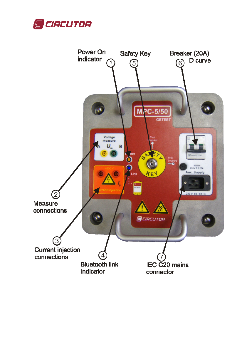
1.- Plug measure connections (2) and current connections (3) depending on
the measure that is going to be performed.
2.- Plug the mains connector (7) to the MPC and to the mains outlet. Device
is designed for AC 230V 50Hz/60Hz. Please ensure that the voltage is
correct before plugging the mains connector. In case of overvoltage, a
F250mA fuse will protect the device.
Note:
Plug the device to a line or generator able to supply the required power:
Recommended power line circuit breaker In should be, at least, 50A curve B, 30A curve C, or
16A curve D, as per EN60898. In case of using lower capacity circuit breakers, MPC won’t be
able to supply the maximun power.
Wiring cross-section and length may limit the maximun capacity of the MPC. Even when the
MPC, due to its current injection system, does not need high current capacity wiring and
connectors, we do recommend to use the bigger cross-section possible, in order to minimize
voltage losses that will affect the MPC maximun capacity. As an example, we show the
maximun earth resistance we can inject 5A, 10A, 25A and 50A, depending on the supply cord
used:
If using a rolled extension cord, it is mandatory to extend it completely before performing the
test. It is recommended to use the maximun cross-section possible, and the minimun cable
length.
Power required > 600V x current to inject
Wiring R máx 5A R máx 10A R máx 25A R máx 50A
3x1.5mm2, 2m
3x1.5mm2, 25m
3x1.5mm2, 50m
3x2.5mm2, 2m
3x2.5mm2, 25m
3x2.5mm2, 50m
120Ω 60Ω 24Ω 12Ω
120Ω 58Ω 20,5Ω 8,5Ω
116Ω 54Ω 17Ω 4,5Ω
120Ω 60Ω 24Ω 12Ω
120Ω 60Ω 22,5Ω 10Ω
119Ω 57Ω 20Ω 7,5Ω
9
Instruction manual
Getest
Page 10

3.- Switch on the circuit breaker (6). The red led will light.
4.- Turn the safety key to the “ENABLED” position. The device is ready.
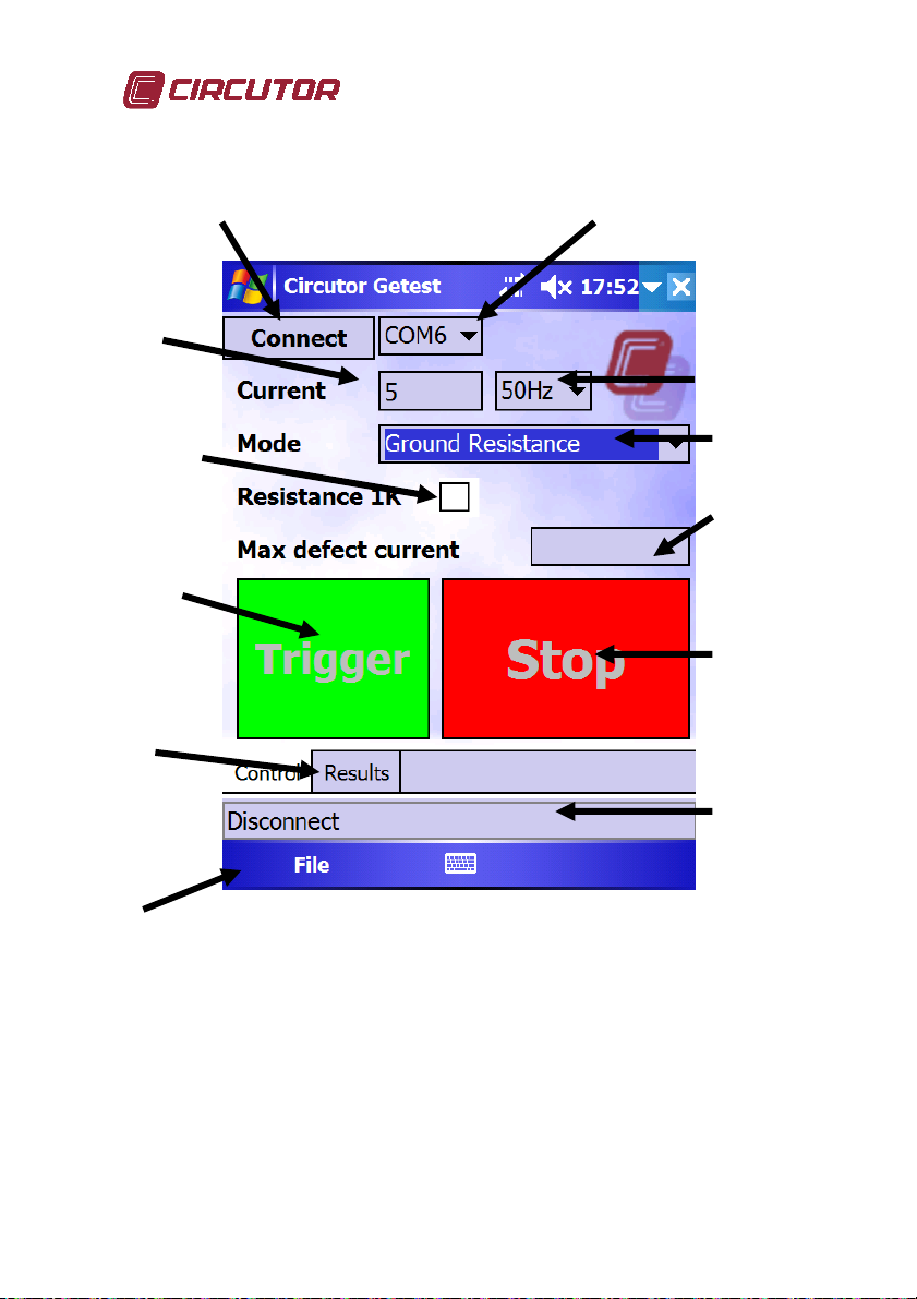
5.- Load the MPC software in the PDA. Select
the language
6.- Select the bluetooth serial port (10) and click
“Connect”(11) (usually, COM6). The status
bar(20) will show “connecting” and “ready”
when connected. If after a couple of second, the
text “Disconnected” appears on the status bar, it
will indicate a problem in the bluetooth link. A
recommendation is to soft-reset (push with the
PDA stylus the reset button) the PDA. If the problem persists, switch off
and on the MPC circuit breaker, and try again. Link is checked every
second, in case of link failure, software will return to the
disconnected state, and MPC will stop doing actions. MPC link
led will light while PDA is connected to the MPC.
7.- Type the current in (12) and select the measure to be performed (14),
depending on the connections done in step 1. Current required depends on
country legislation. Usually, you have to inject 1% of maximun installation
current, and, at least, 5A for distribution transformer station, and 50A for
substations and power plants
10
Instruction manual
Getest
Page 11

º
0
I
×
8.- Type the Maximum Defect Current (16) in order to calculate the step
and contact voltage. Select to measure with a 1K resistor (15), if required.
Step and contact voltages are calculated using this formula:
If erratic voltage is lower than 10% of injected voltage
º0
IV
V
=
If erratic voltage is higher than 10% of injected voltage
VV
V
=
Note: erratic voltage is automatically measured, warning the user in case of value over 50V AC
9.- Press “Start” to initiate the sequence. The sequence consists in:
a) Warning alarm
b) Connecting current output contactor
c) Measuring erratic voltage
d) Test at 25VAC
e) Apply voltage to reach required current
f) Increase voltage if current not reached
g) Apply current in 180º phase
h) Display results
A warning or error will appear if:
- contactor fails
- erratic voltage is over 50VAC
- output is short-circuited
- resistance found is higher than 120 Ohms
- do not have enough power for reaching requested current for the
measured ground resistance
- cannot reach requested current. Possibility to interpolate results
- mains supply drops when applying the current (too high mains
wiring impedance)
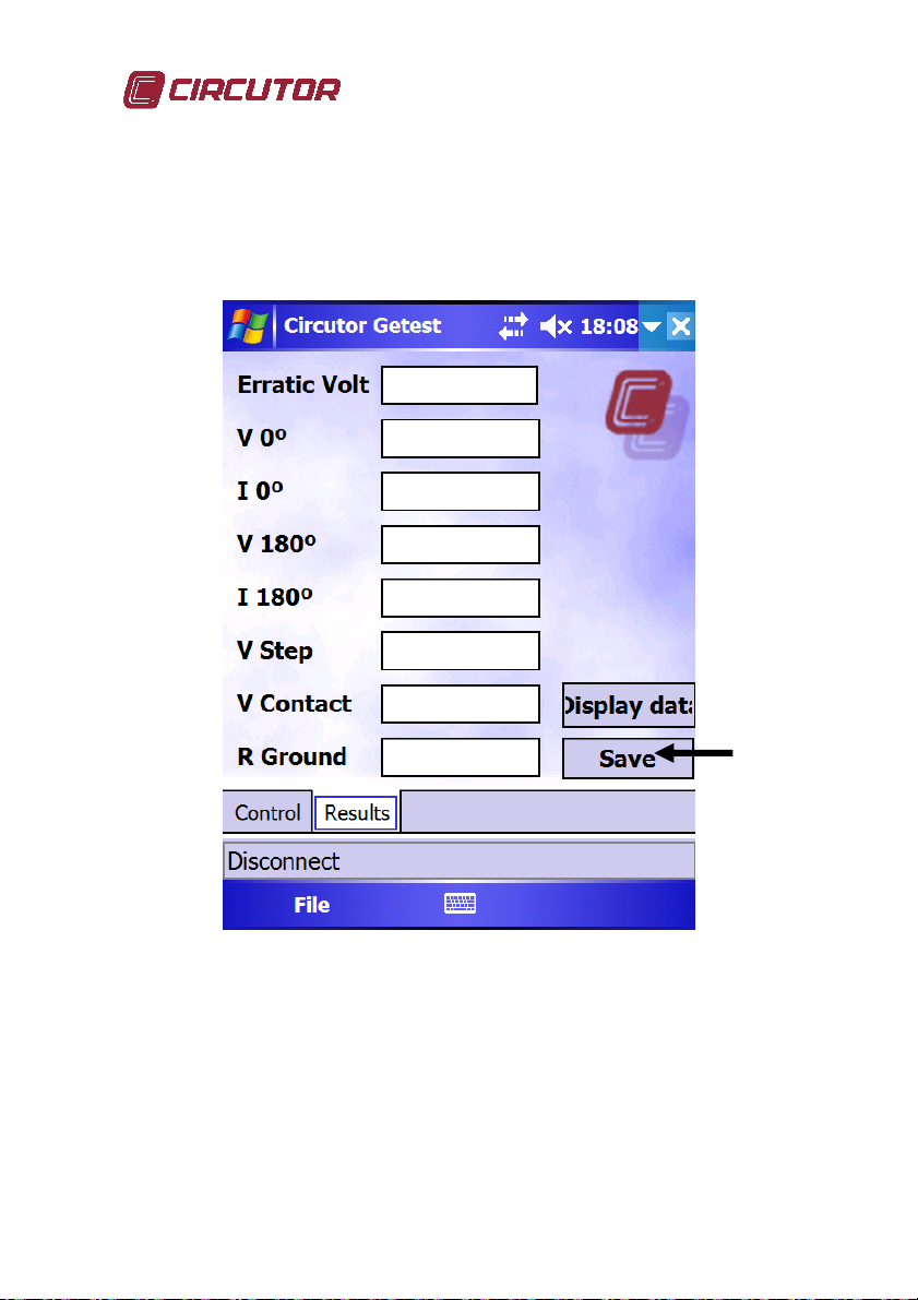
10.- Display results on “DISPLAY” tab (19)
11.- Results can be saved to a file, by pressing the “Save” button, or by
using the pop-up menu “File” (21)
+
max
22
º180º0
V
erratics
ntdefectcure
I
2
max
×−
entdefectcurr
º02
I
11
Instruction manual
Getest
Page 12

Connections
1 m
20 m
20 m
Auxiliary ground
Auxiliary ground
12
20 m
Min. 40 m
Min. 40 m
Ground to
test
Metallic parts
20 m
Ground to
test
Instruction manual
Getest
Page 13

electrode
Ground Resistance
Min. 15m
Ground pike
Min. 15m
Note about auxiliary ground:
The auxiliary ground must be good enough for performing a proper measurement. Take into
account that a bad auxiliary ground will add a resistance in series to the circuit, lowering the
performance of the MPC unit, and therefore, reducing the capacity of injecting current to the
ground.
Corrosion on auxiliary ground terminals are a common cause of problems.
As well, a too dry terrain will affect the auxiliary ground. Pouring water over the surroundings
of the auxiliary ground or the ground pike electrode may solve the issue (safety measures
should be taken to avoid shortcircuit when using/carrying water on electrical instalations)
13
Instruction manual
Getest
Page 14

Connecting to a PC
Using a PDA to control the MPC unit allows to store all data in the PDA
memory, and transfer them to a PC for processing or reporting.
1.- Install Microsoft ActiveSyncTM. The Software can be downloaded from
MicrosoftTM website. This program is the PDA connection manager.
2.- Connect the PDA to the PC. This connection can be done using the USB
cable included, or using a Bluetooth link
3.- ActiveSyncTM automatically detects the PDA and gives the user the
option to synchronize several items (address book, e-mails, files). Pressing
“Cancel” will allow only to exchange files with the PDA (but this is enough
for our purpose)
4.- Open a file browser (like “Explorer”), and browse the “My PC” item. A
“Mobile device” item should appear. This “Mobile device” item is the PDA
memory, browse it, and copy the report files to the hard disk of the PC
5.- Once the file is on the PC hard disk, you are able to open it with any
software for editing, processing or reporting.
Report file format:
- Report file is formatted as a CSV (comma separated values)
- All data is double-quoted
- A 2-rows header is included, with the variable name and its unit
- Data included in the report file are: measuring date, erratic
voltage, voltage and current at 0º and 180º, step or contact voltage
or ground resistance, set current, max. defect current, measuring
mode and 1K resistance indicator
14
Instruction manual
Getest
Page 15

Error and warning messages
Error message Cause Solution
Error:Reading cal data.
Loading default data
Error: Languaje file not
Initialization
found!
ERROR: COM port error An error has occurred
Error: Timeout opening port Bluetooth COM port
Error: Port not opened Bluetooth COM port is
Communications
Error: Invalid current value Typed value is invalid Type in a correct value
Error: Invalid file File to open is invalid or
Setup
Corruption on
calibration data. MPC
unit may be out of
calibration
Corruption on language
file
while connecting or
transferring data
failure
closed
corrupted
Contact vendor, for receiving
instructions for re-calibrate the
instrument, if possible.
Reinstall the PDA software
Close the application and
restart the PDA and the MPC
unit
Close the application and
restart the PDA and the MPC
unit
Close the application and
restart the PDA and the MPC
unit
Open a csv, MPC file
Error: Main contactor failure.
Keeps deenergized. Check
safety key
Error: Cannot reach required
current. Continue
extrapolating data?
Danger: Main contactor
Measuring
failure. Keeps energized
Erratic voltages higher than
50V. Continue?
15
Safety key is in
“disabled” position
MPC unit is not able to
reach the requested
current, due to an
unidentified cause.
If allowed, PDA will
extrapolate the values to
the requested current,
but applying a lower
value.
This is a lifethreatening scenario.
Main contactor is
broken, safety
protection is overriden
This is a lifethreatening scenario.
Erratic voltages flowing
across the ground are
too high. A mains phase
may be tied to ground
Turn the key to the “enabled”
position
Plug the MPC unit to a mains
socket connected to a mains
line with lower impedance, or
to a more powerful generator.
Try to reduce the load.
Contact vendor.
Contact responsible of facility
under inspection.
Instruction manual
Getest
Page 16

Danger: loop resistance too
high, possible connection
error. Check connectons and
ensure nobody is touching the
injection curcuit. Continue?
Warning: Device may not
have enough power for
injecting the required current.
Loop resistance is too high
for the required current.
Continue?
Error: cannot reach required
current, mains voltage drops
down. Mains supply is unable
to power required current. At
least 20KVA are required.
Continue extrapolating data?
Measuring
Warning: Shortcircuit found
at the output. Current limited
to 35 A. Check connections.
Warning: resistance found
higher than 120Ohms. Check
connections. Continue?
This is a lifethreatening scenario.
Resistance found is too
high, it may be caused
by bad connections.
This is a lifethreatening scenario.
Load resistance is too
high for requested
current.
You have requested
more power to the
device than the power
that the mains line may
supply. Power is equal
to the ground resistance
by the square of the
requested current. If
allowed, PDA will
extrapolate the values to
the requested current,
but applying a lower
value.
Measured resistance is
lower than 0.1Ω
This is a lifethreatening scenario.
Load resistance is too
high.
Check connection, ensure
nobody is on the are or
touching the
connectors/electrodes/
auxiliary ground, remove stain
from
connectors/electrodes/auxiliary
ground
MPC will apply maximun
power, but won’t reach the
requested current value
Plug the MPC unit to a mains
socket connected to a mains
line with lower impedance, or
to a more powerful generator
Check connections. It may be
possible that an conductive
plane is inserted in the ground.
Check connection, ensure
nobody is on the are or
touching the
connectors/electrodes/
auxiliary ground, remove stain
from
connectors/electrodes/auxiliary
ground
16
Instruction manual
Getest
Page 17

Specifications
Mains supply
Current injection
Voltage meter
Current meter
Resistance meter
Range : 0 - 150Ω
Accuracy : 2.5% reading + 2 digits
Communications
Class I
Tx Power: +18dBm
Sensitivity: -88dBm
Regulatory approvals:
Voltage 230V+/-20% 50-60Hz
Current 15A AC
Note: Required low impedance in mains supply line for getting maximum performance, as up to
320A 20ms current surges may appear when requesting maximum currents. Mains supply wire
section recommended 2.5mm2 or bigger, in order to have a low line resistance.
Nota2: We recommend to protect the mains power line with a circuit breaker : 50A curve B, or
30A curve C, or 16A curve D, as per EN60898
Max output voltage: 600VAC
Max output current: 50 A.
Max power: (30KVA).
Minimum value limits:
Type: true RMS
Input impedance: 10MΩ or 1KΩ, selectable
Resolution:
Max voltage: 700VAC
Scales: Auto (0.8, 30, 70, 105, 280, 700)
Accuracy : 1% reading + 2 digits
Type : true RMS
Input impedance: less than 0.1Ω
Resolution:
Max current: 100AAC
Scales: Auto (10, 100)
Accuracy : 2% reading + 2 digits
UART protocol, key protected, over Bluetooth v1.2
I
= √(30000/R
max
700VAC scale – 0.5VAC resolution
280VAC scale – 0.1VAC resolution
105VAC scale – 0.1AC resolution
70VAC scale – 0.1VAC resolution
30VAC scale – 0.1VAC resolution
0.8VAC scale – 0.01VAC resolution
100AAC scale – 0.1AAC resolution
10AAC scale – 0.01AAC resolution
FCC Part 15 Subpart C Section 15.247
ETSI EN 300 328
ETSI EN 301 489-1
load
) or I
= 600/R
max
load
17
Instruction manual
Getest
Page 18

ETSI EN 301 489-17
EN61000-3-2, EN61000-3-3
EMC compliancy
Installation category
Connections
Mains: IEC320 C19 16A
Current injection : 4mm safety banana plug CATIV 600V 32A
Voltage meter: 4mm safety banana plug CATIV 600V 32A
Protections
ICP 20A, curve D EN60898
Internal fuse F250mA
Dimensions
Weight : 45kg. Electrodes not included
Device is compliant with EU LVD 2006/95/EC and EMC 89/336/EEC directives.
Due to the nature of the device, an injection of several amps will cause some
disturbance on the mains line, but EMC directive allows this disturbance in this
cases, as this phenomena is inherent to the nature of the device.
As well, depending on the quality of the mains line, mains voltage may drop a 20%
during 20ms, so it is recommended not to connect mains fluctuations sensitive
equipment to the same mains line as the MPC unit
IEC61010 CAT III 600V
Nota: Even when those connectors are specified for nominal currents up to 32A,
they can handle up to 150A during 20ms, without downgrading its performance or.
Size : 28.5x28.5x34cm
18
Instruction manual
Getest
Page 19

Notes
19
Instruction manual
Getest
Page 20

CIRCUTOR S.A
.
Vial Sant Jordi s/n - 08232 -
Viladecavalls (Barcelona) Spain
Tel: (+34) 93 745 29 00
Fax: (+34) 93 745 29 14
20
Instruction manual
Getest
 Loading...