

Page 1

ABSORPTION HYBRID FILTER
FAR-Q TYPE
USER MANUAL
Code M98206701-03-07A
Page 2

------ Absorption filter ------ User Manual, M98206701-03-07A ------ Page 1 of 11------
CONTENTS
1.- BASIC INSTRUCTIONS ......................................................................................................................... 2
1.1.- CHECKING THE CONTENTS OF YOUR PACKAGE ............................................................................. 2
1.2.- MODEL RANGE OF FAR-Q .......................................................................................................... 2
1.3.- SAFETY WARNINGS .................................................................................................................... 3
2.- MAIN FEATURES................................................................................................................................... 3
3.- TYPES ACCORDING TO FILTER COMPOSITION............................................................................... 5
3.1.- MAIN TECHNICAL FEATURES....................................................................................................... 5
3.2.- TECHNICAL FEATURES OF LC FILTERS ......................................................................................... 6
3.3.- DIMENSIONS .............................................................................................................................. 7
4.- INSTRUCTIONS FOR INSTALLING THE FAR-Q FILTERS ................................................................. 7
4.1.- INITIAL CHECKS (BEFORE APPLYING VOLTAGE) ............................................................................. 7
4.2.- REVISION OF EXTERNAL CONNECTIONS (BEFORE APPLYING VOLTAGE)........................................... 7
5.- STARTING-UP OF FAR-Q EQUIPMENT............................................................................................... 9
6.- TROUBLESHOOTING............................................................................................................................ 9
7.- MAINTENANCE...................................................................................................................................... 9
8.- TECHNICAL SERVICE AND WARRANTY.......................................................................................... 10
9.- WIRING DIAGRAM................................................................................................................................11
Page 3
------ Absorption filter ------ User Manual, M98206701-03-07A ------ Page 2 of 11------
1.- BASIC INSTRUCTIONS
This manual is designed to familiarise the user with operating the FAR-Q power factor
correction and filtering equipment in order to get the best from its features.
FAR-Q hybrid filters are specifically developed for power factor correction on systems
with medium harmonic distortion. The aim is to improve power factor and at the same
time, to attenuate harmonics. The operating principle consists in correcting power factor
and at the same time absorbing the 5th and 7th harmonics generated by certain loads
so that they do not get into the system or go towards other nearby loads.
Please read this manual carefully before connecting and switching on the
instrument in order to avoid irreversible damage caused by improper use.
NOTE: So that absorption is effective the hybrid bank must be separate from the other
loads (other lines or users) by a shock reactor or transformer
1.1.- Checking the contents of your package
Please check the following points on receipt of the instrument:
a) The equipment delivered matches your order specifications.
b) Check that the voltage and frequency match the installation's.
c) After unpacking, check that the equipment has not been damaged during
delivery.
d) Check that it is equipped with the following standard items:
- Instruction manual of bank
- Instruction manual of regulator
- Current transformer (not included)
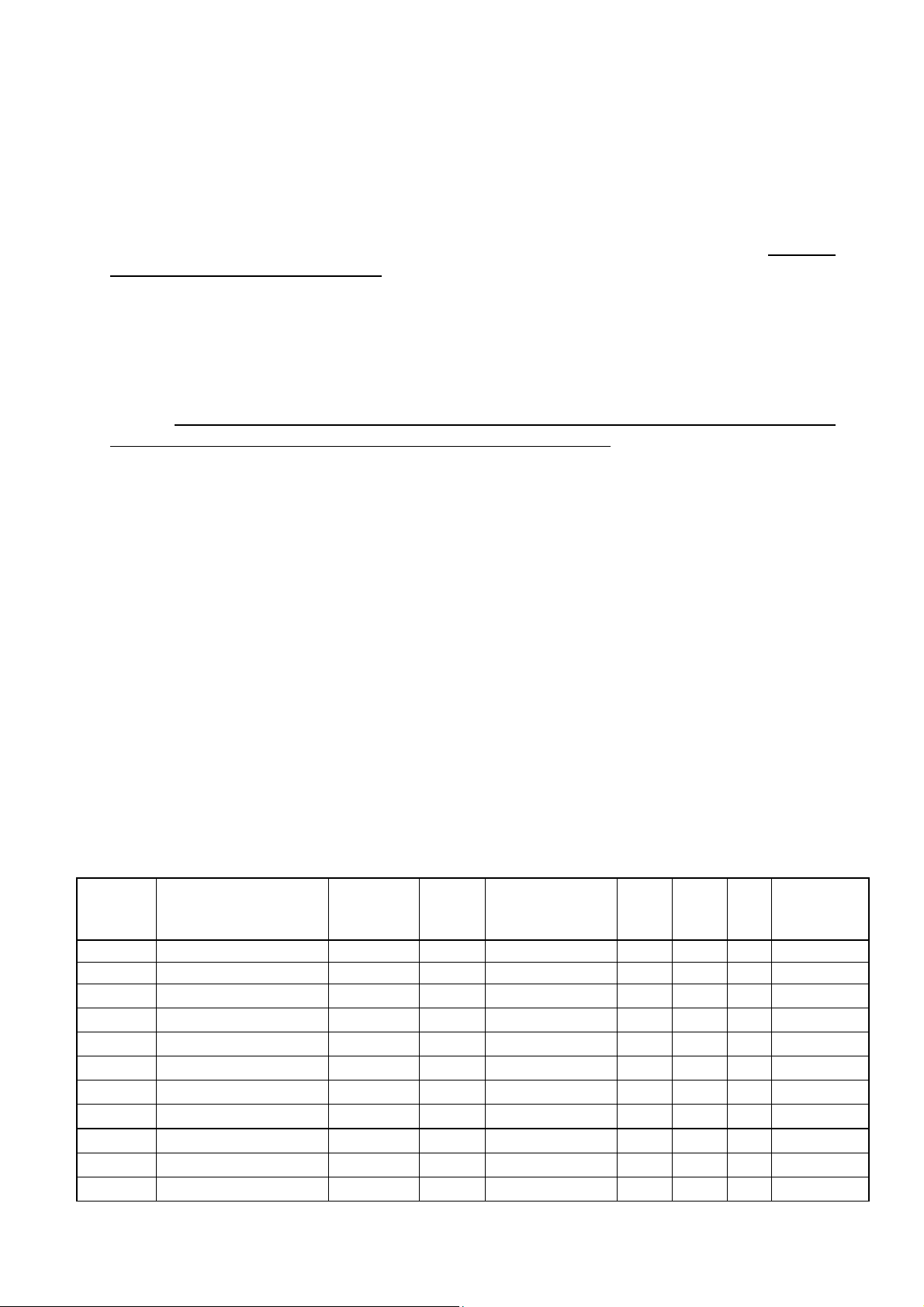
1.2.- Model range of FAR-Q
The range of standard FAR-Q equipment is shown in the following tables.
Table 1.- Standard FAR-Q filters for 50 Hz systems
Q
CODE TYPE (*) VOLTAGE STEPS STEPS x (kvar) Irms 5th 7th CABINET
(V)
R7C101 FAR5-Q6-112.5-400 400
R7C102 FAR5-Q6-150-400 400
R7C103 FAR5-Q6-187.5-400 400
R7C104 FAR5-Q6-225-400 400
R7C105 FAR5-Q6-262.5-400 400
R7C106 FAR5-Q6-300-400 400
R7C107 FAR5-Q6-337.5-400 400
R7C108 FAR5-Q6-375-400 400
R7C109 FAR5-Q8-412.5-400 400
R7C110 FAR5-Q8-450-400 400
R7C111 FAR5-Q8-487.5-400 400
3
4
5
6
4
4
5
5
6
6
7
(A) (A) (A)
3 x 37.5 176 60
4 x 37.5 234 80
5 x 37.5 293 100
6 x 37.5 351 120
37.5 + (3 x 37.5) 410 140
4 x 75 469 160
37.5 + (4 x 75) 527 180
5 x 75 586 200
37.5 + (5 x 75) 644 220
6 x 75 703 240
37.5 + (6 x 75) 761 260
30
40
50
60
70
80
90
100
110
120
130
FR6
FR6
FR6
FR6
FR6
FR6
FR6
FR6
FR8
FR8
FR8
Page 4
------ Absorption filter ------ User Manual, M98206701-03-07A ------ Page 3 of 11------
R7C112 FAR5-Q8-525-400 400
R7C113 FAR5-Q12-562.5-400 400
R7C114 FAR5-Q12-600-400 400
R7C115 FAR5-Q12-637.5-400 400
R7C116 FAR5-Q12-675-400 400
R7C117 FAR5-Q12-712.5-400 400
R7C118 FAR5-Q12-750-400 400
8
8
8
9
9
10
10
7 x 75 820 280
37.5 + (7 x 75) 878 300
8 x 75 937 320
37.5 + (8 x 75) 996 340
9 x 75 1054 360
37.5 + (9 x 75) 1113 380
10 x 75 1171 400
140
150
160
170
180
190
200
FR8
FR12
FR12
FR12
FR12
FR12
FR12
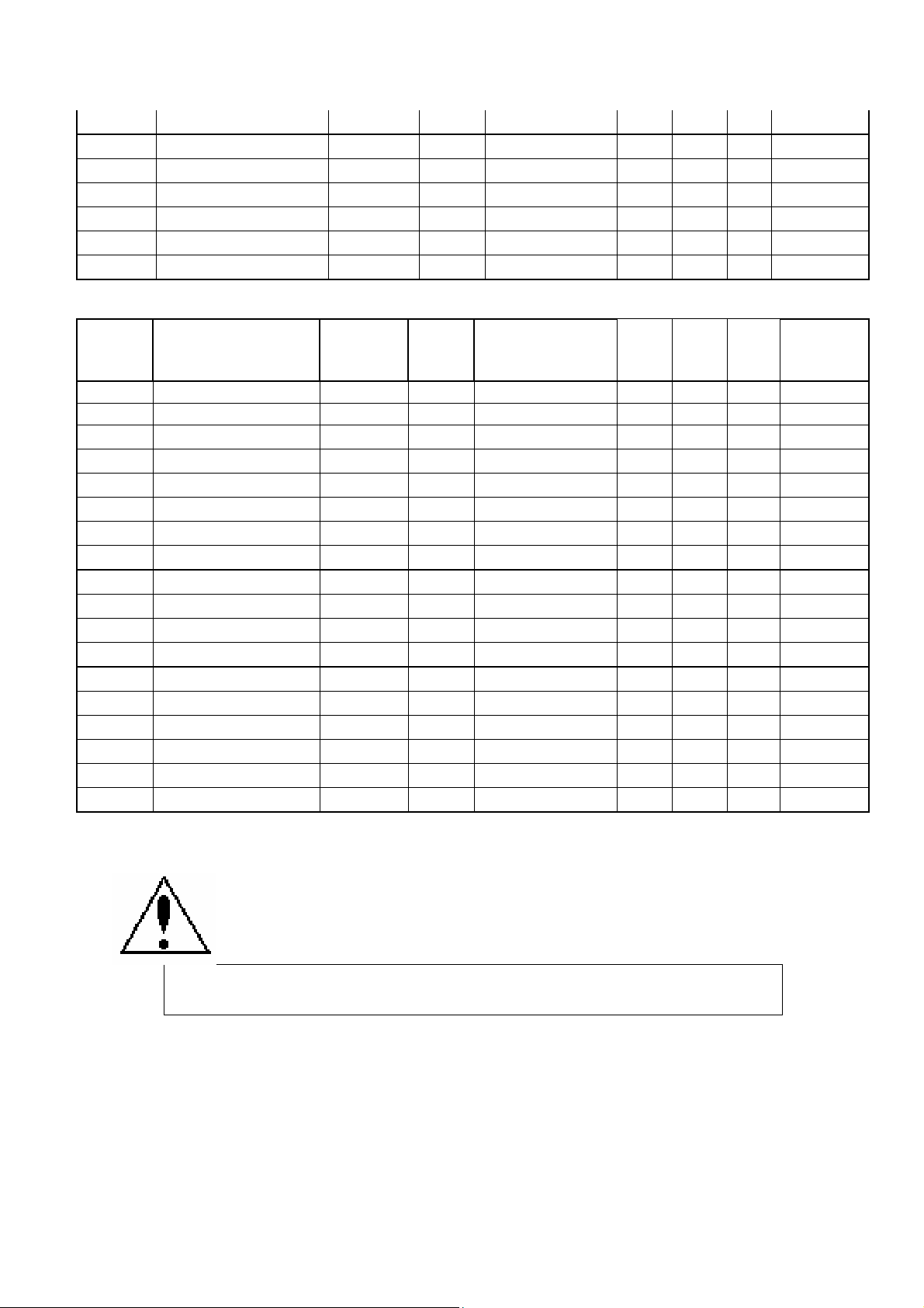
Table 2.- Standard filters for 60 Hz systems
Q
CODE TYPE (*) VOLTAGE STEPS STEPS x (kvar) Irms 5th 7th CABINET
(V)
R7C401
R7C402
R7C403
R7C404
R7C405
R7C406
R7C407
R7C408
R7C409
R7C410
R7C411
R7C412
R7C413
R7C414
R7C415
R7C416
R7C417
R7C418
FAR5-Q6-105-400 480
FAR5-Q6-140-400 480
FAR5-Q6-175-400 480
FAR5-Q6-210-400 480
FAR5-Q6-245-400 480
FAR5-Q6-280-400 480
FAR5-Q6-315-400 480
FAR5-Q6-350-400 480
FAR5-Q8-385-400 480
FAR5-Q8-420-400 480
FAR5-Q8-455-400 480
FAR5-Q8-490-400 480
FAR5-Q12-525-400 480
FAR5-Q12560-400 480
FAR5-Q12-595-400 480
FAR5-Q12-630-400 480
FAR5-Q12-665-400 480
FAR5-Q12-700-400 480
3
4
5
6
4
4
5
5
6
6
7
8
8
8
9
9
10
10
(A) (A) (A)
3 x 35 166 60 30
4 x 35 221 80 40
5 x 35 276 100 50
6 x 35 331 120 60
35 + (3 x 35) 387 140 70
4 x 70 442 160 80
35 + (4 x 70) 497 180 90
5 x 70 552 200 100
35 + (5 x 70) 608 220 110
6 x 70 663 240 120
35 + (6 x 70) 718 260 130
7 x 70 773 280 140
35 + (7 x 70) 829 300 150
8 x 70 884 320 160
35 + (8 x 70) 939 340 170
9 x 70 994 360 180
35 + (9 x 70) 1050 380 190
10 x 70 1105 400 200
FR6
FR6
FR6
FR6
FR6
FR6
FR6
FR6
FR8
FR8
FR8
FR8
FR12
FR12
FR12
FR12
FR12
FR12
1.3.- Safety warnings
This manual contains information and warnings about the FAR-Q hybrid
bank which must be followed to guarantee the proper operation of all
instrument functions and to maintain it in a safe condition.
If the instrument is not installed in accordance with manufacturer's
specifications, the instrument's protection may be damaged.
Check that the protection devices are operating correctly.
2.- MAIN FEATURES
A FAR-Q hybrid filter is formed by various groups of inductances plus a capacitor in
series, located in an appropriate cabinet. Each step is characterised by three
parameters:
1) Power factor to be corrected at 50 or 60 Hz.
2) Harmonic to be filtered, generally 5th and 7th.
Page 5

------ Absorption filter ------ User Manual, M98206701-03-07A ------ Page 4 of 11------
3) Harmonic current capable of absorbing.
Each step is formed by 2 reactors and a 6 terminal capacitor which contains 2 threephase, 3 terminal capacitors each electrically insulated. The operating principle of this
design is that each reactor is connected to each of the three capacitor terminals forming
an LC set tuned to a frequency close to the 5th harmonic and another set tuned near to
the 7th harmonic. The following diagram shows how the step is formed:
Fig. 1 – Standard type at 400V 50Hz, triangle connection
AF1
U1 V1 W1 U1 V1 W1
L1
U2 V2 W2
C1
6 bornes
U11 V11 W11 U12 V12 W12
Paso pequeño: 4 bobinas por fase de 5º armónico 2 bobinas por fase de 7º armónico
Paso grande : 8 bobinas por fase de 5º armónico 4 bobinas por fase de 7º armónico
U2 V2 W2
L2
Fig. 2 – Standard type at 480V 60Hz, star connection
Filter regulation
Filter regulation is via a conventional power factor regulator as with any other standard
capacitor bank. (See regulator manual)
Page 6

------ Absorption filter ------ User Manual, M98206701-03-07A ------ Page 5 of 11------
3.- TYPES ACCORDING TO FILTER COMPOSITION
The types of filters depend on three main parameters:
• Voltage and basic frequency of system
• Step number of filter
3.- TECHNICAL FEATURES
The technical features stated in this manual are for the FAR-Q hybrid banks. However
there may be variations depending on the operating and protection systems.
3.1.- Main Technical Features
Table 3.- Technical features
Standard voltage ........…. 400V and 480 V (1)
Frequency....................... 50 Hz or 60 Hz
Ambient temperature...… -10ºC to +45ºC
General filter switch See table 4
Protection devices (each step) Fuses. Thermostat on L (overload disconnection)
Filter cabinet:
Cabinet protection devices
Filter cabinet
Painted Fe sheet
IP22
Grille: IP21
Standards IEC-61642, EN-60439, IEC-664, EN-60831, EN-60289
(1) Other voltages on request
Cabinets (See figures 3, 4 and 5)
Operation cabinet Sheet metallic, epoxy paint, IP 31
L and C cabinet Ventilation grille, epoxy paint, IP 21
Types and weight (See catalogue)
Dimensions
FA5 Type
2 x FA5 Type
FR6 Type
2 x FR6 Type
(See figures 3, 4 and 5)
One cabinet: L =980 mm, W= 520 mm, H= 2000 mm
Two cabinets: L =980 mm, W= 520 mm, H= 2000 mm
One cabinet: L =1100 mm, W= 800 mm, H= 1850 mm
Two cabinets: L =1100 mm, W= 800 mm, H= 1850 mm
Page 7

------ Absorption filter ------ User Manual, M98206701-03-07A ------ Page 6 of 11------
3.2.- Technical features of LC filters
Table 5.- Filtering groups features
Tuning frequency 1.1 f
Inductance
Core / Wound Directed grain cover / Aluminium strip
Insulating voltage 2kV
L value tolerance <3%
h
Saturation ∆L=5%
Maximum ambient temperature 50ºC
Internal temperature at I
Protecting thermostat 95 ºC
Max. overload Σ(n.In)2
Permanent 20%
Short-time (1 min.) 2 In
<110ºC
nom
1.6 I
nominal
Capacitor
Dielectric Self-healing polypropylene
Operating rated voltage 1.15 U
Short-time overload (10s) 1000 V
Insulating voltage to earth 3 kV
Ambient temperature max. 40ºC
Losses 0.5W/Kva
nom
system
Page 8

------ Absorption filter ------ User Manual, M98206701-03-07A ------ Page 7 of 11------
3.3.- Dimensions
Fig. 3.- Cabinet for FAR-Q6 filters
Fig. 4.- Cabinet for FAR-Q8 type filters
Fig. 5.- Cabinet for FAR-Q12 type filters
4.- INSTRUCTIONS FOR INSTALLING THE FAR-Q FILTERS
4.1.- Initial checks (before applying voltage)
For the FAR-Q hybrid filters to operate properly the following general installation
conditions must be followed:
• The equipment's ventilation conditions must be examined leaving minimum
distances between the sides and bottom of the cabinet and walls ensuring that air
can circulate properly.
• FAR-Q equipment must not be mounted near to heat sources. The maximum
ambient temperature must not exceed 40 ºC. Assemble ventilation over 35 ºC. In
particular FAR equipment must not be installed in direct sunlight.
• FAR-Q equipment must not be mounted in the same line as any other active filter.
• Check that the equipment's rated voltage stated on the technical features board
matches the rated voltage between phases in the system to which ot will be
connected.
• Check that the equipment setting (step and currents) match the installation's
requirements.
4.2.- Revision of external connections (before applying voltage)
Page 9

------ Absorption filter ------ User Manual, M98206701-03-07A ------ Page 8 of 11------
All external connections must be via the terminal boards and the input strip on the FARQ cabinet.
- It is necessary to install a current transformer in order to start (normally In / 5 A) in
accordance with the total current of the installed receivers. The current
transformer secondary line must have the appropriate diameter in terms of its
distance from the regulator (minimum 2.5 mm2).
- The power supply voltage for the regulator is between phases (except when it is a
special single-phase regulator). Voltage must be taken from the two phases
where there is no current transformer. The phase where the current transformer
is installed does not coincide with any of the phases from which voltage is being
taken to supply the regulator.
- The current transformer is installed at a point where all of the load currents to be
corrected plus the capacitor current are passing.
CORRECT INCORRECT
CORRECT
The current transformer has to
be in front of the bank and the
receivers (motors, etc).
Fig. 6.- Attaching the current transformer (CT)
T. C.
S1
S2
INCORRECT
- No capacitor will be
connected because the current
transformer does not give any
signal.
- Check that the CT is not
short circuiting or installed
outside the loads.
S1
T. C.
S2
INCORRECT
- All capacitors in the bank are
connected, but do not
disconnect when the load
decreases. Risk of
overcorrecting the system
without a load.
Page 10

------ Absorption filter ------ User Manual, M98206701-03-07A ------ Page 9 of 11------
Connect the current transformer secondary (S1-S2) onto the terminals marked S1-S2 (1
and 2). If a cos ϕ value appears on the display which does not match, it means that the
phase progress is wrong: invert the connection of the voltage phases on the regulator
(or invert S1-S2 on the current transformer secondary). (See regulator manual)
5.- STARTING-UP OF FAR-Q EQUIPMENT
Follow the steps stated below to start hybrid filter equipment:
1. Check the tightness of the bank's connections.
2. Check if the voltage and frequency levels are correct in the installation.
3. Check that the current transformer is connected on the correct line and that its
polarity, both physical and wiring, are also correct.
4. Check the operation of the regulator without power.
5. Program the regulator in accordance with the instructions in the regulator's
manual.
6. Connect power.
7. Check the capacitor burden.
6.- TROUBLESHOOTING
If this equipment does not work properly when applying voltage, check the following
points:
• If a step does not enter, check the contactor coil and the selector or control relay.
• Check that the step current does not exceed the rated current under normal
operating conditions. A true effective value instrument must be used.
• In the event of a fault, which cannot be resolved using the above paragraphs, please
contact the CIRCUTOR technical service.
IMPORTANT!
• It is recommended that the temperatures of the capacitor walls and the reactor iron
are checked after one hour's operation. The former must not exceed 60ºC and the
latter 85ºC. If not, check the ventilation.
7.- MAINTENANCE
Annual inspection:
• Inspect the bank by eye. No insulation faults or overheating parts should be
detected.
• Check la temperature of the capacitors and reactors (limits stated in paragraph 6).
• Check that the contactor contacts are not showing signs of wear.
• Check that all steps work properly. If not, check voltage supply fuses.
• Check the current in each step. Excess current may be a sign of more harmonics
than the filter can absorb and that it may be necessary to expand the filter.
• Check that there are no power terminals with loose connections which may cause
the cables to overheat.
Page 11

------ Absorption filter ------ User Manual, M98206701-03-07A ------ Page 10 of 11------
8.- TECHNICAL SERVICE AND WARRANTY
CIRCUTOR guarantees its products against any manufacturing fault for a period of one
year from the date of delivery. The warranty does not cover protection devices (fuses)
or operating parts subject to normal wear and tear.
This warranty shall be nullified in the event of improper handling or if the installation
conditions are not followed.
CIRCUTOR has its CONSULTANCY AND TECHNICAL ASSISTANCE services
available for any advice.
NOTE: The intended settings, number of steps, harmonics and the means of grouping
them either fixed or by remote control are configurable and therefore may change
according to order specifications. See setting sheet.
Page 12

------ Absorption filter ------ User Manual, M98206701-03-07A ------ Page 11 of 11------
 Loading...