

Page 1

LV CAPACITOR BANKS WITH STATIC
SWITCHING
EMK SERIES
INSTRUCTIONS MANUAL
M98118701-20-12A-GB
CIRCUTOR, SA
Page 2
EMK series
SYMBOLS AND WARNINGS
Pay attention to the warnings in this manual, which are shown with the following
symbols.
DANGER: Warns of a risk, which could result in personal injury or material
damage.
WARNING: Indicates that special attention should be paid to a specific point.
If you must handle the equipment for its installation, start-up or maintenance, the
following should be taken into consideration:
Incorrect handling or installation of the unit may result in injury to personnel as well
as damage to equipment. In particular, handling with power applied may result in
electric shock, which may cause death or serious injury to personnel. Defective
installation or maintenance may also lead to the risk of fire.
Carefully read the manual prior to connecting the equipment. Follow all the
installation and maintenance instructions for the equipment throughout its working
life. In particular, follow the installation standards indicated in the Low Voltage
regulations and additional technical instructions.
The installation, operation and maintenance of LV equipment must only be carried
out by authorised installers. See the National Code Instructions specifically
defining the requirements that authorised installers must meet in each country.
If in order to install the equipment, you must work in areas that have high-voltage
(HV) equipment installed, then the personnel handling equipment in this area must
be authorised to work in HV installations. Refer to the National Code Instructions,
in each country, which specifically regulate the requirements for personnel and
maintenance companies autorised to handle high-voltage installations.
Instructions Manual M98118701-01-12A 2
Page 3

EMK
series
TABLE OF CONTENTS
1 INTRODUCTION ....................................................................................................................................... 4
2 SAFETY HAZARDS AND WARNINGS .................................................................................................. 4
2.1
H
AZARDS ENCOUNTERED DURING THE INSTALLATION AND START-UP OF ELECTRICAL EQUIPMENT
2.2
S
AFETY WARNINGS
3 RECEPTION, TRANSPORT, HANDLING AND STORAGE ............................................................... 4
3.1
R
ECEPTION PROTOCOL
3.2
T
RANSPORT, LOADING AND UNLOADING, HANDLING AND STORAGE
3.3
S
TORAGE
4 TECHNICAL FEATURES ......................................................................................................................... 6
4.1
L
ABEL WITH THE EQUIPMENT'S FEATURES
4.2
E
LECTRICAL FEATURES
4.3
E
NVIRONMENTAL FEATURES
4.4
M
4.5
E
XTERNAL DIMENSIONS AND WEIGHTS
4.6
C
APACITOR BANK COMPONENTS
4.6.1 Fast regulator ............................................................................................................................. 9
4.6.2 CPC Panel: Zero switching connection control ......................................................................... 9
4.6.3 Power block: ............................................................................................................................... 9
......................................................................................................................................... 6
ECHANICAL FEATURES
.......................................................................................................................... 4
..................................................................................................................... 4
................................................ 5
....................................................................................... 6
.................................................................................................................... 7
........................................................................................................... 7
.................................................................................................................. 7
. ........................................................................................... 7
...................................................................................................... 8
. 4
5 INSTALLATION .......................................................................................................................................10
5.1
P
REPARATION
5.2
I
NSTALLATION LOCATION
5.3
C
ONNECTION OF THE CAPACITOR BANK TO THE GRID
5.3.1 Power circuit .............................................................................................................................11
5.3.2 External isolation and protection elements ...............................................................................11
5.3.3 Auxiliary control voltage ...........................................................................................................11
5.3.4 Earth cable connection ..............................................................................................................11
5.3.5 Connecting the current transformer (CT) ..................................................................................11
6 STATIC CAPACITOR BANK START-UP .............................................................................................13
6.1
B
EFORE START-UP
6.2
S
TART-UP
6.3
C
HECKS ONCE THE CAPACITOR BANK IS CONNECTED AND THE REGULATOR HAS BEEN ADJUSTED
7 MAINTENANCE .......................................................................................................................................15
7.1
S
AFETY REGULATION
7.2
M
AINTENANCE WITH THE CAPACITOR BANK DISCONNECTED
7.2.1 Basic maintenance protocol ......................................................................................................15
7.2.2 Tightening the electrical connections. .......................................................................................15
7.2.3 Key points for inspecting static switches. ..................................................................................15
7.2.4 Key points for inspecting capacitors. ........................................................................................16
7.2.5 Key points for inspecting the regulator .....................................................................................16
7.2.8 Cleaning the cabinet. ..................................................................................................................16
7.3
M
AINTENANCE WITH THE BATTERY CONNECTED
7.4
E
NVIRONMENTAL CONDITIONS
.................................................................................................................................10
...............................................................................................................10
.....................................................................10
..........................................................................................................................13
.......................................................................................................................................13
..14
......................................................................................................................15
..........................................................15
. ...........................................................................16
: .....................................................................................................17
8 GUARANTEE, ...........................................................................................................................................17
9 TECHNICAL ASSISTANCE ....................................................................................................................18
10 TYPICAL STEP DIAGRAM ..................................................................................................................19
11 DECLARATION OF CONFORMITY................................... ¡ERROR! MARCADOR NO DEFINIDO.
Instructions Manual M98118701-01-12A 3
Page 4
EMK
series
1
INTRODUCTION
The purpose of this manual is to assist during the installation, start-up and maintenance of EMKseries low-voltage (LV) capacitor banks with static switching. Carefully read the manual to achieve
the best equipment performance.
2
SAFETY HAZARDS AND WARNINGS
2.1 Hazards encountered during the installation and start-up of electrical equipment.
The installation, operation and maintenance of LV equipment must only be carried
out by authorised installers. See the National Code Instructions specifically
defining the requirements that authorised installers must meet in each country.
Do not access the active elements of a capacitor bank with static switching that
has been previously powered, since it might have residual voltages at the
capacitors. Wait at least 5 minutes after the power supply has been disconnected.
Do not touch the terminals or active parts of the unit until you have verified that
there is no residual voltage at the capacitors. If you have to handle or touch the
terminals or other control panel components while the equipment is connected to
the supply, use adequately insulated personal protection equipment and tools.
After maintenance and before re-applying the power supply to the unit, check that
its enclosure is properly closed and that no items or tools were left inside that
could cause a short-circuit.
Do not open the secondary circuit of current transformer without short-circuiting it
first. The operation of a current transformer with an open secondary will cause an
overvoltage that can damage it and electrocute the person handling it.
2.2 Safety warnings
Apart from the general operational rules, the standards and applicable laws of the
country where the capacitor bank is installed or operated should be strictly
followed.
Installation or maintenance personnel should read and understand this manual
before operating the equipment.
A copy of this manual should always be available to maintenance personnel for
reference purposes.
Connecting the equipment to the public grid will be carried out in compliance with
standard EN-IEC60204-1, on the safety of LV electrical installations.
It is recommended that several personnel are present when handling the
equipment for either installation or maintenance.
If damage or faults are detected during equipment operation, or in circumstances
that compromise safety, immediately stop work in that area and disconnect the
equipment in order to check it while it is de-energized.
Modifying, upgrading or rebuilding the equipment without written authorization from
the manufacturer is prohibited.
3
RECEPTION, TRANSPORT, HANDLING AND STORAGE
3.1 Reception protocol
Make sure that the equipment has not been damaged during transport.
Instructions Manual M98118701-01-12A 4
Page 5
EMK
series
Check that the equipment received matches the order and that its electrical features are
suitable for the grid where it is to be connected.
Check the shipping documentation. The dispatch note number must coincide with the
number marked on the outer part of the unit package.
Unload and transport the equipment in accordance with the instructions in section 3.2
Perform an external and internal visual inspection of the equipment prior to connecting it.
Check that all items on the packing list are present.
If any discrepancy is noticed upon reception, immediately contact the transport
company or CIRCUTOR's after-sales services.
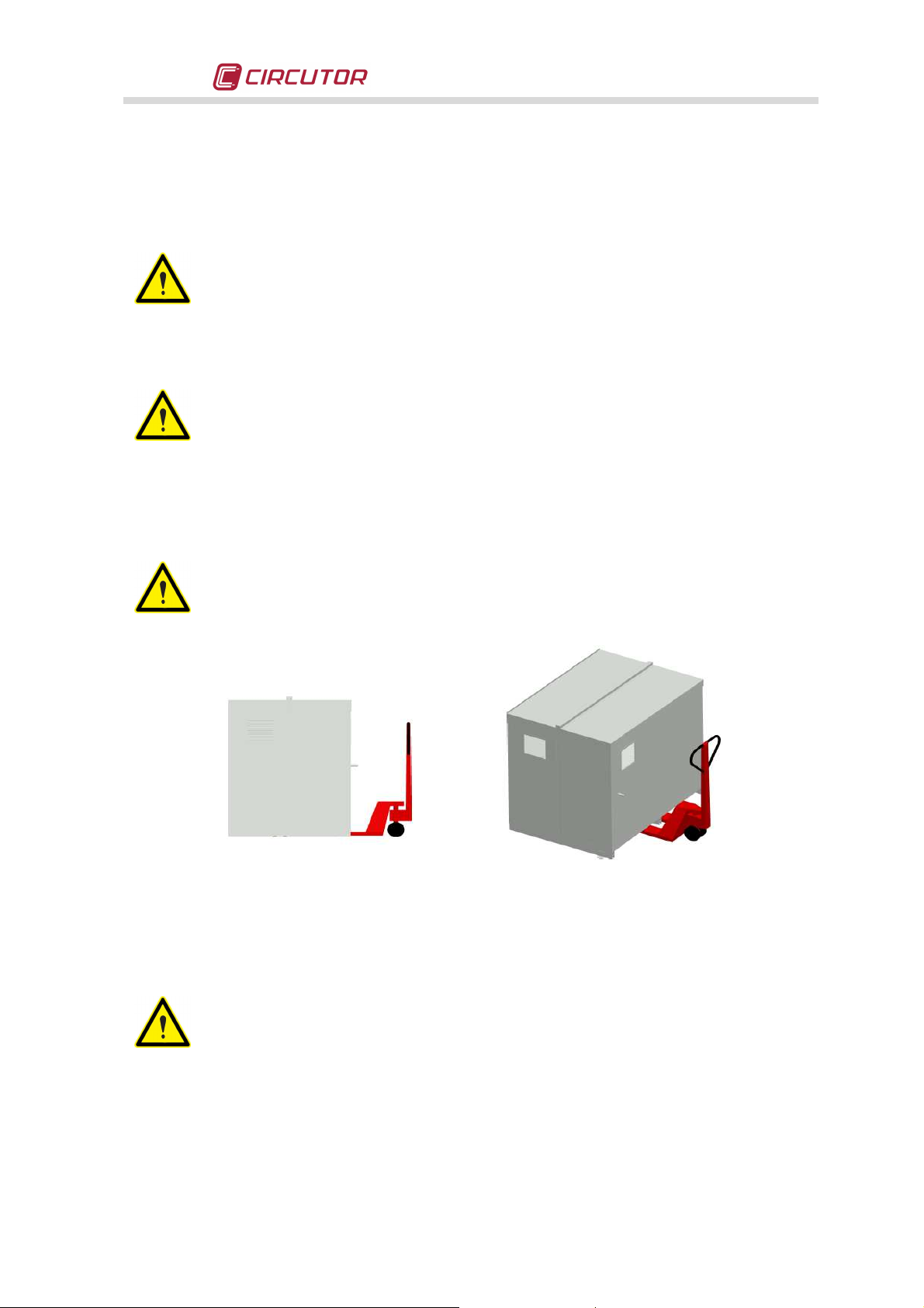
3.2 Transport, loading and unloading, handling and storage
The transport, loading and unloading and handling of the equipment must be
carried out with proper precautions and using the proper manual or mechanical
tools to prevent damaging the equipment.
If the equipment is not to be immediately installed, it must be stored at a location
with a firm and level floor and the storage conditions listed in the technical features
section must be observed. In this case, it is recommended that the equipment be
stored with its original protective packaging.
To move the equipment a short distance, the unit's base support profiles facilitate handling with a
pallet jack or forklift.
The centre of gravity of some units may be found at a considerable height.
Therefore, when handling with a forklift, it is recommended that the equipment be
securely fastened and that no abrupt operations are made. The equipment should
not be lifted more than 20 cm over the ground.
Fig. 3-1 .-Transport with pallet jack
When unloading and moving the equipment, use a forklift with forks long enough to support the
entire length of the base. Otherwise, the forks should be long enough to support at least ¾ of said
depth. The forks must be flat and supported firmly by the base. The cabinet must be raised by
placing the forks underneath the profile that supports the equipment. (Fig. 3-2).
There might be an offset in the centre of gravity from the centre of the cabinet, as a
result of the uneven distribution of loads inside the equipment. The necessary
precautions must be taken to prevent the equipment from tipping over during abrupt
operations.
Instructions Manual M98118701-01-12A 5
Page 6
EMK
series
Fig. 3-2 .-Unloading with a Forklift
3.3 Storage
The following storage recommendations shall be followed for the static capacitor banks:
- Avoid placing it on uneven surfaces.
- Do not store in outdoor areas, humid areas or areas exposed to the splashing of water.
- Avoid hot spots (maximum environmental temperature: 45 ºC)
- Avoid saline and corrosive environments.
- Avoid storing the equipment in areas where a lot of dust is generated or where the risk of
chemical or other types of contamination is present.
- Do not place any weight on top of the equipment cabinets.
4
Technical features
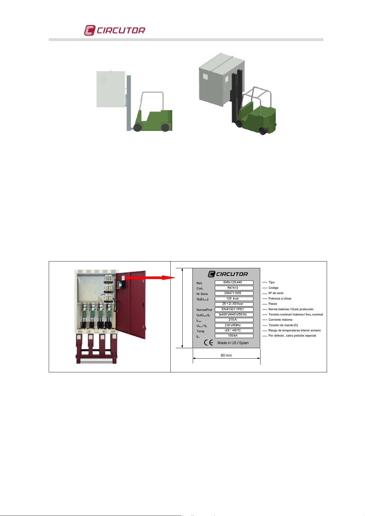
4.1 Label with the equipment's features
The label with the equipment's features is located inside it, generally next to the PF regulator (refer
to Fig. 4-1).
95 mm
Fig. 4-1.- Features label
Instructions Manual M98118701-01-12A 6
Page 7

Dimensions (mm)
EMK
series
4.2 Electrical features
- Operating voltage and nominal frequency: Un / f , listed on the label
- Design voltage: Un+ 10% (440 V for 400 V equipment)
- Nominal power and distribution of steps: Qn and composition, (see label)
- Total loss: Typical 1 W/kvar
- Residual discharge voltage: 75 V after 3 minutes
- Overload capacity: 1.3 In in all items
- Auxiliary voltage: U
NOTE: In general, use a 1.5 mm2 cable to supply external power.
If “Internal” , is marked in the label , this circuit does not require external power.
-
Current Transformer: Secondary Winding 5 A ,
, listed on the label.
aux
NOTE: Minimum cable section 2.5 mm2.
(Transformer In/5 A)
- Compliance with Standards UNE EN 61921 and EN-61642
- Protection elements:
NH Fuses
, gL curve, minimum calibre 1.5 In)
- Capacitor features:
Capacity tolerance: ± 10%
Insulation level from earth: 3 kV /50 Hz
Impulse test: 15 kV , ray type wave 1.2/50 µs
Protection elements: Internal fuses and over-pressure system
Compliance with Standards EN 60831
4.3 Environmental Features
- Capacitor max. temperature Category C in accordance with EN 60831-1
Maximum for 1h 50ºC
24h average 40ºC
- Cabinet ventilation For outdoor t
Annual average 30ºC
> 30ºC, forced ventilation
amb
must be used for the cabinet
- Maximum relative humidity: 80%
-
Altitude: 1000 m
forced ventilation)
(For higher altitudes, use always
4.4 Mechanical features
- Protection degree: Marked on the label:
- Paint Oven dried epoxy type
- Standard colours RAL 7035 Grey ; RAL 3005 Wine Red
4.5 External dimensions and weights.
Model
EMK4
EMK6
EMK8
EMK12
Width Height
(*)
880 1805 575 172
1180 1805 575 186
1530 1805 575 200
2360 1805 575 371
Depth
(*)
Maximum dimensions
Max.
weight
(kg)
Instructions Manual M98118701-01-12A 7
Page 8

EMK
series
4.6 Capacitor bank components
Fig. 4-3 shows the different models of EMK static capacitor banks and their essential components.
Note that some protection elements are optional and others may be replaced with equivalent
models or adapted to the specific application.
Fig. 4-2 .- EMK Capacitor bank components
Instructions Manual M98118701-01-12A 8
Page 9

EMK
series
From the electrical standpoint, the unit is made up of the following blocks:
4.6.1 Fast regulator
Static capacitor banks are equipped with computer Max f, computer Smart f or computer Plus
TF fast regulators. The outputs of these regulators are static; that is to say, instead of an output via
relay contact they have a semiconductor-based switch which allows them to perform operations in
rapid succession, practically every network cycle. This type of output is prepared to drive COM and
ACT inputs on CPCxx zero switching controller
Fast regulators enable regulation with minimum delay, generally between 20 and 100 ms. (see
manual for the specific regulator being used)
4.6.2 CPC, zero switching controller
Static capacitor banks are equipped with CPCxx controllers (xx means that there are different
types according to the network voltage, control voltage and control type).
The role of the CPCxx is to control the switching of the thyristors at zero voltage during the turn
ON operation, thus avoiding current transients. The typical connection diagram of a single step is
shown in Fig. 4-3 and in more detail in the simplified wire diagram in section 10.
CPC controllers are powered with an auxiliary voltage U
. The standard CPCs are mainly used
aux
for networks with Umax = 440 V, nevertheless they have a dual-voltage supply circuit able to be
supplied at a rated voltage of 230V or 400 V (±10%) . There are special controllers, type CPC3i,
which are designed to operate on networks up to 690V. Notice that even for the latter case, the
auxiliary control voltage, U
must be 400 V or 230 V. The CPC3i controllers allow three-phase or
aux
individual phase-phase control, thanks to an RS-485 bus. However, the standard control is through
a voltage-free static contact (semiconductor-based), which opens or closes the circuit between the
controller's COM and ACT terminals.
Fig. 4-3 .- Basic connection diagram of the CPCxx to the power block
4.6.3 Power block:
The power block of an EMK unit is made up of 3 to 12 thyristors + capacitor groups, depending on
the type. Each group consists of a 6-terminal capacitor (three single-phase capacitors), three (*)
thyristor modules attached to a cooling heatsink and the suitable protection elements addapted to
the module's rated power (1 fuse and 1 inductance limiter of di/dt per phase).
(*) On some models the three thyristor modules are integrated into a single encapsulated package
Instructions Manual M98118701-01-12A 9
Page 10

EMK
series
5
INSTALLATION
5.1 Preparation
The CIRCUTOR EMK static capacitor banks are prepared for an easy installation and start-up.
Remove the equipment's packaging and verify that the unit's electrical features are suitable for
connection to the grid at the site to be installed. For this, check the features label located inside
the cabinet, next to the regulator, refer to Fig. 4-1 as an example. Key data to be checked are:
- Mains frequency and voltage, Un / fn.
- Nominal power of the capacitor bank, Qn (kvar) and steps composition
- Current consumption, I
(See label) . This current is the one to be considered when
max
selecting the proper size of the power supply cable and the circuit breakers and other
protection elements to be connected upstream the equipment.
- Auxiliary control voltage, U
. This voltage is used to feed the CPCxx controllers and
aux
other auxiliary elements. The line is usually protected by a circuit breaker of suitable size
(See section 5.3.3)
- Environmental conditions. (See section 4.3)
5.2 Installation location
It is important to maintain a minimum distance around the equipment to facilitate the cooling. In
self-standing cabinets, the back and front sides of the cabinet must be kept at least 50 cm away
from walls and other equipment to allow for ventilation. Regarding the sides, it is recommended
that a separation of 10 cm be maintained between adjacent equipment. On wall hung cabinets, it
is recommended that at least 20 cm of separation should be maintained between the sides of
adjacent equipment.
NOTE: Static units have one or more aluminium heatsinks for cooling the thyristors. Periodically
clean these heatsinks with a brush or with compressed air and ensure that they have maximum
ventilation.
Make sure that the equipment can be accessed easily.
The environmental conditions of the location where the equipment is installed must not surpass
the limits established in the technical features (See section 4.3)
To ensure proper ventilation, the unit must be installed in a vertical position.
In accordance with most National Electric Codes and LVD, once the unit is installed, it must be
protected against electric shock hazard due to direct or indirect contacts; therefore, a circuit
breaker and an earth leakage protection relay should be provided for the capacitor bank's supply
line.
5.3 Connection of the capacitor bank to the grid
Check that the rated voltage of the capacitor bank matches the voltage between
phases of the grid where it is to be connected. Also check the voltage of the auxiliary
circuits U
For feeding cables into the capacitor bank cabinet, always use the entry points
. Regarding this issue, refer to section 5.3.3
aux
available for this purpose.
Do not drill holes in the cabinet walls for feeding cables through them or for installing
support brackets. Drilling will produce shavings that can cause short-circuits.
Instructions Manual M98118701-01-12A 10
Page 11

A current transformer (CT)
, external to the capacitor bank
, must
be installed to
EMK
series
5.3.1 Power circuit
• Connect input terminals L1, L2 and L3 (power circuit supply) to the grid using proper sized
cables in accordance with the National Electric Code or LVD. Generally, the phase cables use
the following colour code: L1 (black), L2 (brown), L3 (grey). If a 230 V auxiliary voltage is
required, we can use an internal 400V/230V transformer or use the neutral and connect it to
terminal N (blue colour cable).
• In order to determine the size of the phase cables, the user must consider a maximum
expected current equal to 1,5 times the I
feeding the neutral cable to obtain the auxiliary voltage, U
shown on the equipment's label. In case of
max
, it shall have a cross section of at
aux
least 1.5 mm2 .
5.3.2 External isolation and protection elements
• In case the capacitor bank does not have an internal switch or circuit breaker, it must be
connected to a line with an external switch or circuit breaker.
The protection elements, isolation switches and/or switches that are added
externally to the capacitor bank must be of a minimum size to withstand a current
1.5 times greater than the I
indicated on the label
max
If an earth leakage protection for the capacitor bank is installed, its sensitivity and
trip delay must be adjustable.
• For capacitor banks equipped with a standard regulator measuring the current only in one of
the supply phases, we advise installing the current transformer (CT) in the phase connected to
L1 (black cable). The CT's S1 and S2 outputs must be connected then to the terminals with
the same name on the capacitor bank. For more details about the connection of the CT, see
paragraph 5.3.5
5.3.3 Auxiliary control voltage
• The auxiliary control circuits include those related to the power supply of the CPC controllers
and other control or protection devices and ventilation units. The CPC controllers, up to 400 V,
usually are supplied at 400 V
from phase to phase voltage. In other applications supplied
AC
above 440 V and up to 690V, the CPC must be supplied from an auxiliary voltage of 230 VAC
• The auxiliary power supply of 230 V, can be obtained from an internal V
primary
/230V
transformer or using phase-neutral from a 400V supply (connect neutral to terminal N with a
blue colour cable).
5.3.4 Earth cable connection
• Connect the earth terminal of the capacitor bank, placed inside the equipment's cabinet (see
Fig. 4-2) to the external earth connection. The earth cable cross section shall be selected in
accordance with the admissible current limits established in the National Electric Code or LVD
5.3.5 Connecting the current transformer (CT)
measure the total of load current plus the capacitor bank current (see Fig. 5-1).
The standard transformer must have a nominal output of 5A at the secondary.
We recommend connecting the CT to phase L1 , with the cable running from line to
load in the direction P1 to P2 , and connecting the secondary (terminals S1, S2) to
the terminals with the same name on the capacitor bank (see Fig. 5-1).
Avoid the flow of current through the CT's primary (P1-P2) before connecting the
secondary side to the capacitor bank's S1 and S2 terminals. If the CT must be
installed while the installation is running, short-circuit S1 and S2 while they are not
connected to the capacitor bank.
Instructions Manual M98118701-01-12A 11
Page 12

EMK
series
• The rated current of the CT primary winding must be equal to or slightly greater than the size
of the installation's main switch. The CT must be able to measure the maximum forecast
current expected to be consumed by all the loads.
Fig. 5-1 .- Installation of the current transformer (CT) (external)
• The connection point of the CT for a bank that compensates an entire installation is after the
installation's main switch.
• To prevent excessive attenuation of the CT signal, the minimum cross section of the cable
connecting the secondary of CT to terminals S1-S2 in the capacitor bank, must be at least 2.5
mm2.
Fig. 5-2 .- CT and neutral connection terminals if required
• Once the CT cables are installed, disconnect the jumper connecting terminals S1 and S2 on
the capacitor bank (see Fig. 5-3)
Fig. 5-3 .- Jumper for short-circuiting the secondary winding of the current transformer (CT).
Instructions Manual M98118701-01-12A 12
Page 13

Safety
EMK
series
Any time you wish to change or disconnect a current transformer that is already
installed, it is important to install the jumper connecting S1 and S2.
6
STATIC CAPACITOR BANK START-UP
6.1 Before start-up
The static capacitor banks include a power factor regulator. In order to perform the proper start-up
adjustments, the basics of operation of such regulator must be known. For this reason, all
capacitor banks come with the specific manual of the regulator used. Find this manual and
have it available for the start-up process. For the case of static capacitor banks, the regulator
should be a fast type as computer Max f, computer Smart f, computer PlusTF or equivalent,
having static output.
In order to carry out the proper adjustment of the regulator controlling a static
capacitor bank, the minimum load at the installation must be at least 30% to 40%
of the nominal load of such installation. If the load is much less than the rated load
and only a few steps need to be connected , you can manually force the
connection of all the steps , to check them all.
During low load periods, manually connecting the entire capacitor bank steps is not
recommended, since in some cases resonance with the installation's power
transformer could occur, thus causing strong over-currents.
6.2 Start-up
Apply the safety regulations listed in section 2 of this manual before operating the
equipment.
The standards, Electric Code Regulations and other applicable laws of the country
where the capacitor bank is installed or operated should be strictly followed.
• Ensure the inner circuit breaker protecting the regulator (fig. 4.3) is connected
• Connect the power supply to the panel and check that the regulator display illuminates
immediately. Otherwise, stop and check the previous paragraph.
• Check the regulator's cos ϕ indication. If the indication is out of the range 0.5 to 1, it may be
possible that the current transformer and / or the power supply to the regulator are improperly
connected. Most of the regulators use only one current transformer. In this case, connect as
per fig. 5-2 (place the current transformer on phase L1 and take the power supply voltage from
phases L2 and L3)
Instructions Manual M98118701-01-12A 13
Page 14

EMK
series
Fig. 6-1 .- Computer Max f regulator
(Picture provided as an example. It may not
coincide with the model used on your unit).
Fig. 6-2 .- Connection of a regulator with only one CT
(If using computer PLUS, 3 current transformers are used. See the
specific manual of the computer PLUS regulator)
• Once ensured that the regulator is properly connected, adjust the regulator parameters for the
installation you are attempting to compensate. For this, follow the instructions of the particular
PF regulator manual, supplied with the equipment.
6.3 Tests once the capacitor bank is connected and the regulator has been adjusted
• After start-up, make sure that the equipment is operating properly. A sign of proper operation,
once the steady state of the regulator has been reached, is a cosϕ indication on the display
close to 1. In addition, the reactive energy meter should stop counting.
• Check that the power supply voltage does not exceed the nominal value +10% (IEC 60831-1)
• Check the current absorbed by each capacitor step. Under normal working conditions, it must
be close to the nominal values (see Table 6.4) and never more than 1.3 times this value. A
permanent consumption in all the capacitor steps over the nominal value, may be caused by
the presence of harmonics in the grid or by an excessively high power supply voltage. Both
circumstances are harmful for capacitors and control panels. If there is an unusual
consumption in only some of the capacitors, it is a sign that there are damaged capacitors.
• In accordance with the IEC 60831-1 Standard, the capacitors are prepared to operate at the
permanent voltage assigned and with an overvoltage of up to 10% during 8 hours every 24
hours.
Check the working temperature of the capacitors after they have been operating for
24 hours. The capacitor case must be under 40ºC.
Instructions Manual M98118701-01-12A 14
Page 15

FUSE BASE
TORQUE (Nm)
EMK
series
7
MAINTENANCE
7.1 Safety regulation
Keep in mind the safety regulations listed in section 2 of this manual before
operating the equipment.
The standards, National Electric Code, and applicable laws of the country where
the capacitor bank is to be installed or operated should be strictly followed.
7.2 Maintenance with the capacitor bank disconnected
7.2.1 Basic maintenance protocol
Monthly
• Visually inspect the capacitors
• Check the protection fuses
• Control the environmental temperature (average of 30 ºC. In accordance with IEC 60831 ).
• Control the supply voltage (especially during periods of low load, it must not exceed the
nominal value +10%).
Six-monthly
• Keep the capacitor terminals clean.
• Check that the thyristors are not short-circuited. To do so, cut the regulator's power supply and
check that there is no current in any of the capacitor phases.
• Check that the capacitor currents, in any of the phases, is not lower than 75% neither
greater than 120% of the rated value. Check also that there is no a phase unbalance greater
than 15%.
Annually
• Check the capacitor's microfarads of the different steps. An indirect verification can be
performed by checking that the consumption matches the value stated in Table 6.4, with a
maximum deviation of ± 10%.
• Check the tightness of all terminal connections on the different power elements.
• Inspection of the fuses.
- Power circuit: NH fuses. Check continuity and temperature.
- Control Circuit: Uni-polar circuit breaker, check continuity and temperature
7.2.2 Fuses inspection.
• The fuses and fuse bases should not be blackened and their connections must be tight. The
tightening torques for fuse bases are as indicated in the table below:
Table 7-1.- Tightening torques of the power cables to the fuse bases
NH-00 15.2
7.2.3 Key points for inspecting static switches.
• Check that the plastic parts are not blackened and do not show signs of burning or hardening.
• Check that the head is properly inserted
• Check the tightness of cables and terminals, as shown in table 6-2
• The terminals must be clean.
• In dirty environments (dust, sawdust, metal trimmings, etc.). Vacuum the dust and solid
remains regularly. There is no estimated time frame for cleaning, it depends on the amount of
dirt that penetrates the capacitor bank's cabinet.
Instructions Manual M98118701-01-12A 15
Page 16

THYRISTOR TYPE
Tightening of power cable
s
CFB, CSB
EMK
series
Table 7-2.- Tightening torques of the cables to the fuse bases
Semikron 3.5 Nm
IXYS 3.25 Nm
7.2.4 Key points for inspecting capacitors.
• Inspect the cables and terminals. They should not be overheated or blackened.
• The terminals must be clean
• The slow discharge resistors must be in good condition (they should not be open or show
signs of burns)
• Check the tightness of capacitor terminals, as shown in Table 7-3
Table 7-3.- Tightening torques of the cables on the capacitor bank terminals
Capacitor
Power terminal
(Nm)
Earth terminal
(Nm)
21 6.2
7.2.5 Key points for inspecting the regulator
• Check that the regulator does not show signs of deterioration and the display lits normal
• Inspect the cables and terminals. They should be clean and should not be hardened or
overheated
• Check the connections and the insertion of removable terminal strips, if used:
- The terminal strips must be well fastened on pluggable regulators
- Check that the terminals are tightened properly. The recommended torque is 0.6 Nm
7.2.8 Cleaning the cabinet.
• Remove any solid particles
• Clean the inside of the cabinet
• Clean ventilation grilles
7.3 Maintenance with the capacitor bank connected.
• Check that the main switch turns on and off, without having to force the mechanism
• If there is individual earth leakage protection for the capacitor bank, check its proper operation
by pressing the test button
• Check that the auxiliary control voltage is within the tolerance limits. If the capacitor bank has
an autotransformer, check that it is in good condition and does not show signs of deterioration
• Force the connection and disconnection of the capacitors in manual mode. (refer to the
regulator manual before carrying out this operation) and perform the following checks:
- Check that the steps connect and disconnect properly
- Check that there is no consumption in any phase with the step disconnected. If there is
consumption this means that some of the thyristors are defective.
- Check the consumption of the different steps, in each phase. The normal values are
shown in , in accordance with the power of each step , in accordance with the power of
each step in Table 7-4.
Instructions Manual M98118701-01-12A 16
Page 17

CURRENT
230 V
400 V
EMK
series
Table 7-4.- Nominal consumption of the capacitor steps, depending on its power
POWER
2.5 kvar
5 kvar
7.5 kvar
10 kvar
12.5 kvar
15 kvar
20 kvar
25 kvar
30 kvar
40 kvar
50 kvar
60 kvar
70 kvar
80 kvar
In In
6.28 A 3.6 A
12.56 A 7.2 A
18.85 A 10.8 A
25.12 A 14.4 A
31.41 A 18 A
37.7 A 21.6 A
50.24 A 28.8 A
62.82 A 36 A
75.4 A 43.2 A
100.48 A 57.6 A
125.64 A 72 A
150.8 A 86.4 A
175.92 A 101.1 A
200.96 A 115 A
NOTES:
• When the consumption of the steps is 25% less than stated in and the voltage is within the
tolerance limits, this is a sign of degradation of the capacitors. These must be replaced with a
suitable spare part if these symptoms are detected in a step.
• When the consumption of the steps is 10% more than stated in, this can be caused by the
presence of resonances. If this is detected, measure the THD(V) of network voltage (should be
below 5%).
7.3.3 Regulator Checkings
Refer to the manual of the specific regulator used in the capacitor bank. This
manual is always supplied with the capacitor bank.
• Make sure that there are no damaged segments on the display (abnormal brightness).
• Make sure that regulator's keyboard is working properly:
- Enter Setup and check the adjusted values
- Force the manual connection and disconnection of a step.
7.4 Environmental Conditions:
• Check that the maximum environmental conditions listed in section 4.3 are observed
8
GUARANTEE,
CIRCUTOR guarantees its products against any manufacturing defect for two years after
equipment delivery.
CIRCUTOR will repair or replace any defective factory product returned during the guarantee
period.
No returns will be accepted and no unit will be repaired or replaced if it is not
accompanied by a report indicating the defect detected or the reason for the return.
Instructions Manual M98118701-01-12A 17
Page 18

EMK
series
The guarantee will be void if the equipment has been improperly used or the storage, installation
and maintenance instructions listed in this manual have not been followed. "Improper usage" is
defined as any operating or storage condition contrary to LV Regulations or that surpasses the
limits indicated in the technical and environmental features of this manual.
In particular, capacitor units are very sensitive to adverse environmental conditions, to
temperatures above the established limits and overloads produced by the absorption of harmonic
currents. Therefore, special care must be taken to not surpass these usage conditions.
CIRCUTOR accepts no liability for possible damage to equipment or other parts of the installation,
therefore it will not cover any possible penalties resulting from possible failure, improper
installation or "improper usage" of the equipment.
Consequently, this guarantee does not apply to failures occurring in the following cases:
1. Overvoltages and/or electrical disturbances in the supply
2. Water, if the product does not have the appropriate IP classification
3. Poor ventilation and/or excessive temperatures
4. Improper installation and/or lack of maintenance
5. Buyer repairs or modifications without the manufacturer's authorisation
9
Technical assistance
CIRCUTOR can provide advice and technical assistance for the planning and installation of
capacitors, automatic power factor correction equipment and harmonics filters.
CIRCUTOR, SA
Vial Sant Jordi, s/n
08232 Viladecavalls (Barcelona)
Technical Assistance Service: 902 449 459 (Spain)
Tel. +34 93 745 29 00 (International)
E-mail: sat@circutor.es
Fax: +34 93 745 29 14
Web: www.circutor.es
E-mail: reactiva@circutor.es
Instructions Manual M98118701-01-12A 18
Page 19

EMK
series
10
TYPICAL DIAGRAM of ONE STEP
Instructions Manual M98118701-01-12A 19
 Loading...