

Page 1

STATIC SWITCHING MODULES
FOR
POWER FACTOR COMPENSATION
EM. SERIES
(CIRCUTOR Patent Nr. 542258)
INSTRUCTIONS MANUAL
M98116701-20 / 07A
Page 2

----- Static switching modules EM ---------- M98116701-20 Pág: 1
TABLE OF CONTENTS
1 GENERAL DESCRIPTION _________________________________________________ 2
2 TYPES __________________________________________________________________ 2
2.1 Technical characteristics of EM modules: __________________________________________ 3
3 EMF and EMB MOUNTING INSTRUCTIONS _________________________________ 4
4 WIRING INSTRUCTIONS FOR EQUIPMENT BASED ON MODULES EM. _________ 5
5 BLOCK DESCRIPTION OF EM MODULES.___________________________________ 6
5.1 Static Power Block (BPE) _______________________________________________________ 6
5.2 Zero Switching Control Board (CPC). _____________________________________________ 7
6 START UP OF PF COMPENSATORS BASED ON EM MODULES. ______________ 7
6.1 Initial checking (before connecting to supply) _______________________________________ 7
6.2 Checking immediately after the supply connection ___________________________________ 8
7 TROUBLE SHOOTING ____________________________________________________ 8
8 MAINTENANCE. _________________________________________________________ 9
9 TECHNICAL SERVICE AND WARRANTY ___________________________________ 9
10 BASIC WIRE DIAGRAM OF AN EM MODULE_______________________________ 10
Page 3
----- Static switching modules EM ---------- M98116701-20 Pág: 2
1 GENERAL DESCRIPTION
The EM series of static switching modules are the basic blocks used to build static capacitor
banks for power factor (PF) compensation. These static switched capacitor banks use thyristors
instead of electromechanical switchgears to connect and disconnect the capacitors. The static
system is the most convenient in case of large and fast fluctuations of the load current (load
changes lasting a few milliseconds to several seconds). The advantages of the static system are
the connection at zero voltage and the disconnection at zero current, thus avoiding transients. The
ON-OFF switching speed can be as high as 1 operation every 20 ms
Each EM module is used to switch ON and OFF a capacitor step. Notice that a fast power factor
controller like the COMPUTER...f must be used to regulate the power factor using a static
switched capacitor bank . The standard PF regulators aren't fast enough to compensate the fast
load fluctuations.
2 TYPES
The range of static switching modules consists of four main groups :
•
Three phase with fuses , designated as EMF-xx-xxx
•
Three phase without fuses , designated as EMB xx-xxx
Note: The symbol “x" means a reference number or character which depends on the type.
There are different types depending on the operating voltage and the power of capacitor they are
able to operate (see tables 1 to 4)
In the following paragraphs we designate generically as EM modules when we refer to general
or common characteristics valid for all the types.
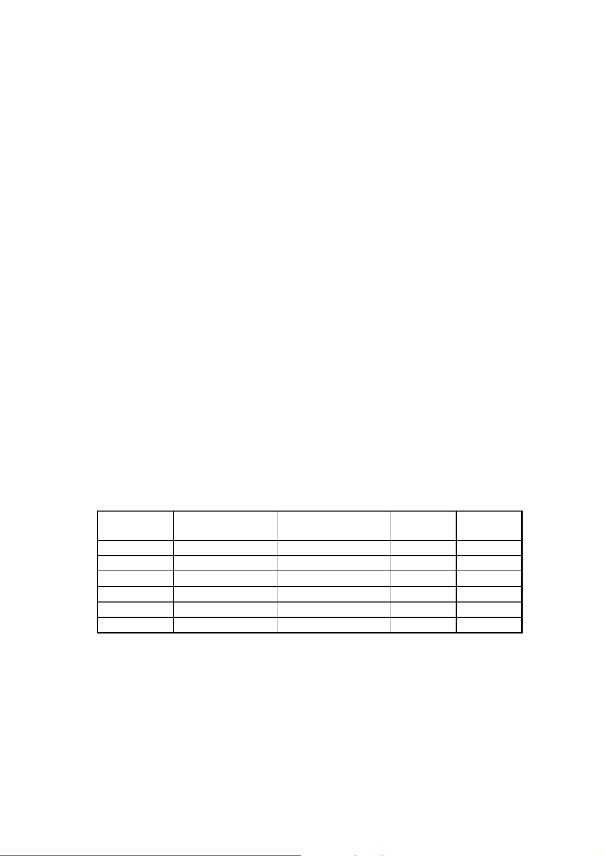
TABLE 1.- Three phase EMF modules (Built in fuses)
CODE OPERATING
VOLTAGE
TYPE POWER
(kvar)
LOSSES
(W)
R41133 380-400V EMF-40/400 40 115
R41136 380-400V EMF-60/400 60 175
R41137 380-400V EMF-80/400 80 230
R41111 220-240 V EMF-25/230 25 125
R41112 220-240 V EMF-37,5/230 37,5 190
R41114 220-240 V EMF-45/230 45 225
Page 4

----- Static switching modules EM ---------- M98116701-20 Pág: 3
EXTERNAL
TABLE 2.- Three phase EMB modules
(External fuses must be included)
CODE OPERATING
VOLTAGE
R41233 380-400V EMB-40/400 40 80 A gl
R41236 380-400V EMB-60/400 60 125 A gl
R41237 380-400V EMB-80/400 80 160 A gl
R41211 220-240 V EMB-25/230 25 80 A gl
R41212 220-240 V EMB-37,5/230
R41214 220-240 V EMB-45/230 45 160 A gl
Note: Losses are approx. the same as modules EMF of equal size.
2.1 Technical characteristics of EM modules:
Standard supply voltage (power block)
Frequency
Rated power of C step
Overload capability.
Protections
Fuses
dV/dt
Thermostat
di/dt
Max. ambient temperature
Max. heatsink temperature
Protection degree
Dimensions
Mounting distances
Weight
Control of the static switch:
Auxiliary supply at terminals B1-B2
Control method
V
I
A-C
open circuit
A-C
closed circuit
TYPE POWER
(kvar)
37,5 125 A gl
400 Vac / 230 Vac (other values up to 690
Vac , on request)
50 / 60 Hz (either)
see table of types
1,5 Inom during 1 minute
NH type (size according to rated current)
RC protection at 1000 V/µs
90 ºC (Opens ENABLE circuit A-C)
100 A/µs ( L= 12µH , not included , must be
mounted in series with the Capacitor)
40 ºC
80 ºC
IP00
See figure 1
10,5 kg.
400 Vac / 230 Vac (Shown in the label)
Potential free contact between terminals A
and C
(see table 5)
20 V cc
Max. 7 mA
TYPE
FUSES
Page 5

----- Static switching modules EM ---------- M98116701-20 Pág: 4
Table 5.- ON-OFF operation method
Terminals
A - C
OPEN CIRCUIT DISCONNECTED
CLOSED CIRCUIT CONNECTED
Standards: EN 60.439 ( IEC 439 , UNE 20 098) , IEC 146 , CSA 22.2 Nº14
Accessories: COMPUTER...f , TP series current transformers , 6 terminals capacitors
Note: On request, CIRCUTOR may supply special static modules for operation up to 550
V
RMS.
voltages exceeding 440 V
3 EMF AND EMB MOUNTING INSTRUCTIONS
To get optimal working conditions of the static switching modules, the following
recommendations must be followed:
The modules should be installed inside a closed cabinet taking care of the fixing and cooling
conditions. To ensure the proper cooling conditions, certain minimum clearances must be left
free between the EM modules and other elements into the cabinet , as shown in the figure 1
The CPC board and the power block are specially sized for high voltage in case of line
STATIC SWITCH
STATUS
a) Dimensions
Page 6

----- Static switching modules EM ---------- M98116701-20 Pág: 5
b) Minimum clearances for cooling
Figure 1.- Dimensions and mounting distances
• As a thumb rule, the cabinet cooling system should provide approximately an air flow of
6 m3/h for each kW of total losses (including all the elements into the cabinet, fuses, lamps,
switchgears, coils, etc.)
• The EM modules must be placed in the upright position with the heatsink channels oriented
in the vertical sense. The top and bottom parts of the heatsink must be kept free for air
circulation
• Avoid mounting the EM modules close to hot components or devices emitting heat. The
maximum ambient temperature inside the cabinet should be kept below 45 ºC.
4 WIRING INSTRUCTIONS FOR EQUIPMENT BASED ON MODULES EM.
When building static power factor compensation equipment, based on the EM modules, the
following wiring instructions must be followed:
• For this application the three phase EMF or EMB modules must be used together with three
single phase capacitors or a three phase capacitor with 6 terminals (internally built as three
single phase caps.). The connection of each EM module to the corresponding step of
capacitors must be as shown in figure 2.
Page 7

----- Static switching modules EM ---------- M98116701-20 Pág: 6
Figure 2.- Basic wire diagram for a three phase EM module.
• Three phase EMF or EMB modules consist of three circuit branches, each having a power
pack with two anti-parallel thyristors. Each module is provided with three input terminals and
six output terminals.
• Three phase EMB modules must be protected with three external fuses in series with L1, L2
and L3 line cables. The fuses type must be in accordance with the EM size and is given in
table 2. EMF modules have built in fuses.
• Single phase modules, EMB...-M, must be protected with two external fuses in series with
L1, and L2 line cables. The type and size of the fuses must be in accordance with the EM size
(see table 4)
5 BLOCK DESCRIPTION OF EM MODULES.
All the EM modules consist of two basic blocks: (See figures 2 and 3).
5.1 Static Power Block (BPE)
This block basically consists of two thyristors for each phase , the fuses (only in EMF... modules)
, the heatsink , the fan and the protection thermostat. The size of the power components depends
on the Q(kvar) of the capacitor which has to be switched
Page 8
----- Static switching modules EM ---------- M98116701-20 Pág: 7
5.2 Zero Switching Control Board (CPC).
The CPC control board receives the enable signal for ON-OFF operation of the static switch.
This enable signal is usually given by a PF regulator (usually a COMPUTER...f) and is
connected to terminals A and C. The static switch operation according to this signal, is resumed
in table 5 in the technical characteristics.
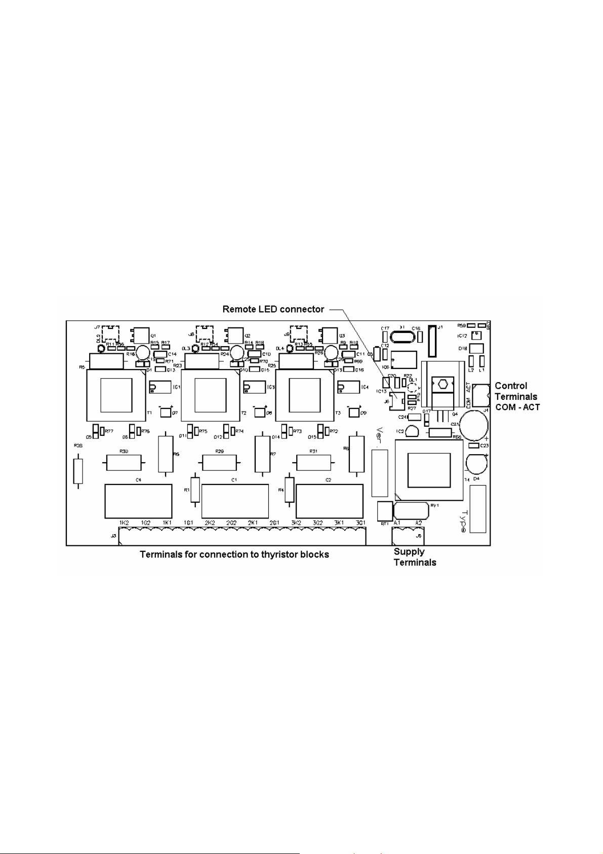
The CPC has three red LEDs , one for each phase , showing whether the phase is ON or OFF.
The card has also a set of 12 terminals connected to the thyristors through optocouplers, to obtain
the synchronism for switching at zero voltage. The CPC must be supplied from an auxiliary
source from terminals B1 and B2 (See module label for nominal value). The ENABLE
terminals, ACT-COM, are connected to external terminals A and C.
Notice that all the synchronism between the CPC card and the thyristor blocks are coupled
through optoisolated devices and the firing signals are coupled through pulse transformers,
therefore , the electronic circuits and the power block are galvanically isolated.
Figure 4 .- Layout of CPC printed circuit board
6 START UP OF PF COMPENSATORS BASED ON EM MODULES.
To start up static PF compensation equipment, based on the EM modules, follow the steps
below.
6.1 Initial checking (before connecting to supply)
• Check that the rated voltage for the EM modules, shown in the characteristics label, conforms
with the rated voltage available in the site where the equipment has to be installed
• Check that the EM modules are supplied through the auxiliary supply terminals B1-B2 with
the rated voltage value shown in the label.
• Check that the power of EM modules is in accordance with the size of the capacitors which
have to operate.
Page 9

----- Static switching modules EM ---------- M98116701-20 Pág: 8
• Check that the connections between the EM modules and the capacitors correspond to one of
the figures 2 o 3.
• The external connections of a static capacitor bank are identical to those of a standard
capacitor bank using electromechanical switchgears. The section 10 shows a diagram
illustrating the internal and external wiring of a single EM module, including the connections
between the CPC board and the thyristor blocks.
• Check the connections between the EM modules , the PF regulator (COMPUTER...f) and
the current transformer (CT). For details concerning the regulator adjustment see the
instructions manual of COMPUTER...f. See also the figure 5 showing the right location of
CT in the installation.
Figure 5.- Location of the current transformer (CT)
6.2 Checking immediately after the supply connection
¡ ATTENTION! Before any attempt of manipulation on the PF correction equipment wait 5
minutes for capacitors discharge after the supply has been removed.
In static capacitor banks, where the load has great fluctuations, it must be considered normal that
the switches operate very often. Nevertheless if the PF regulator operates the capacitor steps very
quickly when the load remains constant, check the COMPUTER...f adjustments.
7 TROUBLE SHOOTING
The capacitor bank should operate only if there is a minimum load. If the equipment does not
work properly check the following points:
• If the display of the COMPUTER...f does not light or gives a very slight bright , check the
supply voltage and the fuses (power and control fuses)
• If the display of the COMPUTER...f shows an error, see the COMPUTER... instructions
manual. Check also the CT connections
• If the LED pointing to the letter C is lighting , means that the COMPUTER...f sees a
capacitive load. If an inductive load is expected, then check the CT phase settings and the CT
connections.
Page 10

----- Static switching modules EM ---------- M98116701-20 Pág: 9
• During the normal operation , the number of connected steps can be seen by the indication
LED in the front panel of COMPUTER...f. Check that the number of connected steps
conforms with the Nr. of steps shown by the COMPUTER..f LEDs.
• To see whether a step is connected or not, see the green LED at the CPCm card. The green
LED and the three red LEDs must light simultaneously , otherwise indicates that there is one
of the phases which does not work properly.
• If one of the steps is never connected, try to force its connection by jumping the terminals A
and C in the corresponding EM module. If the step connects in the forced mode (check the
current in each phase with a current clamp) , then the fault is probably in the COMPUTER...f
or in the wiring.
• If there are some inactive steps and the COMPUTER...f shows a lack of compensation ,
check the settings of such COMPUTER...f.
• Once the normal operation is achieved , check if the current consumption of each step is
correct, according to its rated power (Current is shown in the capacitor label). An excess of
consumption may be due to an excess of supply voltage or to the presence of harmonics.
• In case of a faulty operation which may not be solved with the above indications , contact the
CIRCUTOR S.A. technical service.
¡IMPORTANT!
After one hour in normal operation , check the temperature of the heat sinks. It must be
below 80 ºC. In case of higher temperature check the cooling conditions.
8 MAINTENANCE.
Yearly inspection:
• Inspect the equipment visually and check the temperature of the capacitors and the thyristor
heat sinks.
• Check that all the steps operate when necessary. Otherwise check the fuses.
• Check that the supply voltage is within the limits.
• Check that the current of each step is in accordance with its labelled value. A higher current
may be due to the presence of harmonics. A low current may indicate a faulty capacitor.
• Check that there are not loose connections at the terminals.
9 TECHNICAL SERVICE AND WARRANTY
All CIRCUTOR products are covered by a warranty of 1 year in case of any manufacturing
default . The warranty does not cover the protection elements like fuses or other, neither the
elements subject to ageing in normal service.
This warranty will not be applicable in case of wrong manipulation or in case that the rules of
installation have not been respected.
CIRCUTOR offers to all its customers the assistance of its TECHNICAL AND ENGINEERING
DEPARTMENTS.
Page 11

----- Static switching modules EM ---------- M98116701-20 Pág: 10
10 BASIC WIRE DIAGRAM OF AN EM MODULE
 Loading...