

Circutor eHome T1C16, eHome T2C32, eHome T1C32, eHome T1C32 N, eHome T1C16 N Instruction Manual
...Page 1

INSTRUCTION MANUAL
Indoor electric vehicle charging
eHome Series
(M094B01-03-17A)
Page 2

2
eHome
Instruction Manual
Page 3
3
Instruction Manual
eHome
PENDIENTE DE VALIDACIÓN
SAFETY PRECAUTIONS
DANGER
Warns of a risk, which could result in personal injury or material damage.
ATTENTION
Indicates that special attention should be paid to a speci c point.
Follow the warnings described in this manual with the symbols shown below.
If you must handle the unit for its installation, start-up or maintenance, the following
should be taken into consideration:
Incorrect handling or installation of the unit may result in injury to personnel as well as damage
to the unit. In particular, handling with voltages applied may result in electric shock, which may
cause death or serious injury to personnel. Defective installation or maintenance may also
lead to the risk of re.
Read the manual carefully prior to connecting the unit. Follow all installation and maintenance
instructions throughout the unit’s working life. Pay special attention to the installation standards of the National Electrical Code.
Refer to the instruction manual before using the unit
In this manual, if the instructions marked with this symbol are not respected or carried out correctly, it can
result in injury or damage to the unit and /or installations.
CIRCUTOR, SA reserves the right to modify features or the product manual without prior noti cation.
DISCLAIMER
CIRCUTOR, SA reserves the right to make modi cations to the device or the unit speci ca-
tions set out in this instruction manual without prior notice.
CIRCUTOR, SA on its web site, supplies its customers with the latest versions of the device
speci cations and the most updated manuals.
www.circutor.com
Page 4

4
eHome
Instruction Manual
CONTENTS
SAFETY PRECAUTIONS ���������������������������������������������������������������������������������������������������������������������������������������3
DISCLAIMER ����������������������������������������������������������������������������������������������������������������������������������������������������������3
CONTENTS �������������������������������������������������������������������������������������������������������������������������������������������������������������4
REVISION LOG �������������������������������������������������������������������������������������������������������������������������������������������������������5
INFORMATIVE NOTE ��������������������������������������������������������������������������������������������������������������������������������������������� 5
1�- VERIFICATION UPON RECEPTION ����������������������������������������������������������������������������������������������������������������� 6
2�- PRODUCT DESCRIPTION �������������������������������������������������������������������������������������������������������������������������������� 6
3�- DEVICE INSTALLATION �����������������������������������������������������������������������������������������������������������������������������������8
3�1�- PRELIMINARY RECOMMENDATIONS �����������������������������������������������������������������������������������������������������8
3�2�- EMPLACEMENT ����������������������������������������������������������������������������������������������������������������������������������������9
3�3�- ELECTRICAL WIRING �������������������������������������������������������������������������������������������������������������������������������9
3�3�1�- eHome POWER SUPPLY �������������������������������������������������������������������������������������������������������������������9
3�3�2�- POWER SUPPLY - LINE DIMENSIONING ���������������������������������������������������������������������������������������10
3�3�3�- CHARGING POINT MAXIMUM OUTPUT CURRENT ����������������������������������������������������������������������� 10
3�4�- OPENING THE DEVICE ���������������������������������������������������������������������������������������������������������������������������10
3�5�- POWER SUPPLY LINE CABLE INSERTION ������������������������������������������������������������������������������������������13
3�5�1�- USING THE REAR CABLE INSERTION OPENING ������������������������������������������������������������������������� 13
3�5�2�- USING THE BOTTOM CABLE INSERTION OPENING� ������������������������������������������������������������������14
3�6�- WALL FIXATION PROCEDURE ���������������������������������������������������������������������������������������������������������������14
3�6�1�- NEEDED MATERIAL �������������������������������������������������������������������������������������������������������������������������14
3�6�2�- CONSIDERATIONS ��������������������������������������������������������������������������������������������������������������������������� 15
3�6�3�- INSTALLATION ���������������������������������������������������������������������������������������������������������������������������������15
3�7�- CABLE SUPPORT ����������������������������������������������������������������������������������������������������������������������������������17
3�7�1�- INSTALLATION ���������������������������������������������������������������������������������������������������������������������������������18
3�8�- ELECTRICAL INSTALLATION ����������������������������������������������������������������������������������������������������������������� 18
3�8�1�- POWER SUPPLY LINE PROTECTIONS ������������������������������������������������������������������������������������������18
3�8�2�- POWER SUPPLY LINE CONNECTION ��������������������������������������������������������������������������������������������19
3�9�- CLOSING THE DEVICE ���������������������������������������������������������������������������������������������������������������������������20
3�10�- CHECKING THE DEVICE STATUS ��������������������������������������������������������������������������������������������������������21
4�- OPERATION ����������������������������������������������������������������������������������������������������������������������������������������������������22
4�1�- Product description ��������������������������������������������������������������������������������������������������������������������������������22
4�1�1�- eHome T1C16, T1C32, T2C16, T2C32, T1C16 N and T1C32 N MODELS �������������������������������������22
4�1�2�- eHome T1C32-A, T1C32-B, T1C32-A MID, T2C32-A, T2C32-B AND T2C32-A MID MODELS ������ 25
4�2�- FIRMWARE VERSION �����������������������������������������������������������������������������������������������������������������������������29
4�3�- CHARGING PROCEDURE ����������������������������������������������������������������������������������������������������������������������� 29
4�4�- OPERATING ERROR DETECTION ���������������������������������������������������������������������������������������������������������31
4�5�- CURRENT LIMIT SELECTOR ������������������������������������������������������������������������������������������������������������������32
4�6�- REMOTE CONTROL INPUT ��������������������������������������������������������������������������������������������������������������������33
4�7�- RESIDUAL CURRENT (eHome TxC32-A, - B, -A MID models) �������������������������������������������������������������34
4�7�1�- RESET THE RESIDUAL CURRENT DEVICE �����������������������������������������������������������������������������������34
4�7�2�- MAINTENANCE OF RESIDUAL-CURRENT DEVICE (RCD) ����������������������������������������������������������� 35
4�7�3�- ENERGY METER ������������������������������������������������������������������������������������������������������������������������������35
4�8�- CirBEON (Optional) ��������������������������������������������������������������������������������������������������������������������������������36
4�8�1�- LEDs BAR STATUS CONSIDERATION �������������������������������������������������������������������������������������������36
4�8�2�- CONNNECTIONS CirBEON �������������������������������������������������������������������������������������������������������������� 37
5�- TECHNICAL FEATURES ��������������������������������������������������������������������������������������������������������������������������������38
6�- MAINTENANCE AND TECHNICAL SERVICE ������������������������������������������������������������������������������������������������40
7�- GUARANTEE ���������������������������������������������������������������������������������������������������������������������������������������������������40
Page 5
5
Instruction Manual
eHome
PENDIENTE DE VALIDACIÓN
REVISION LOG
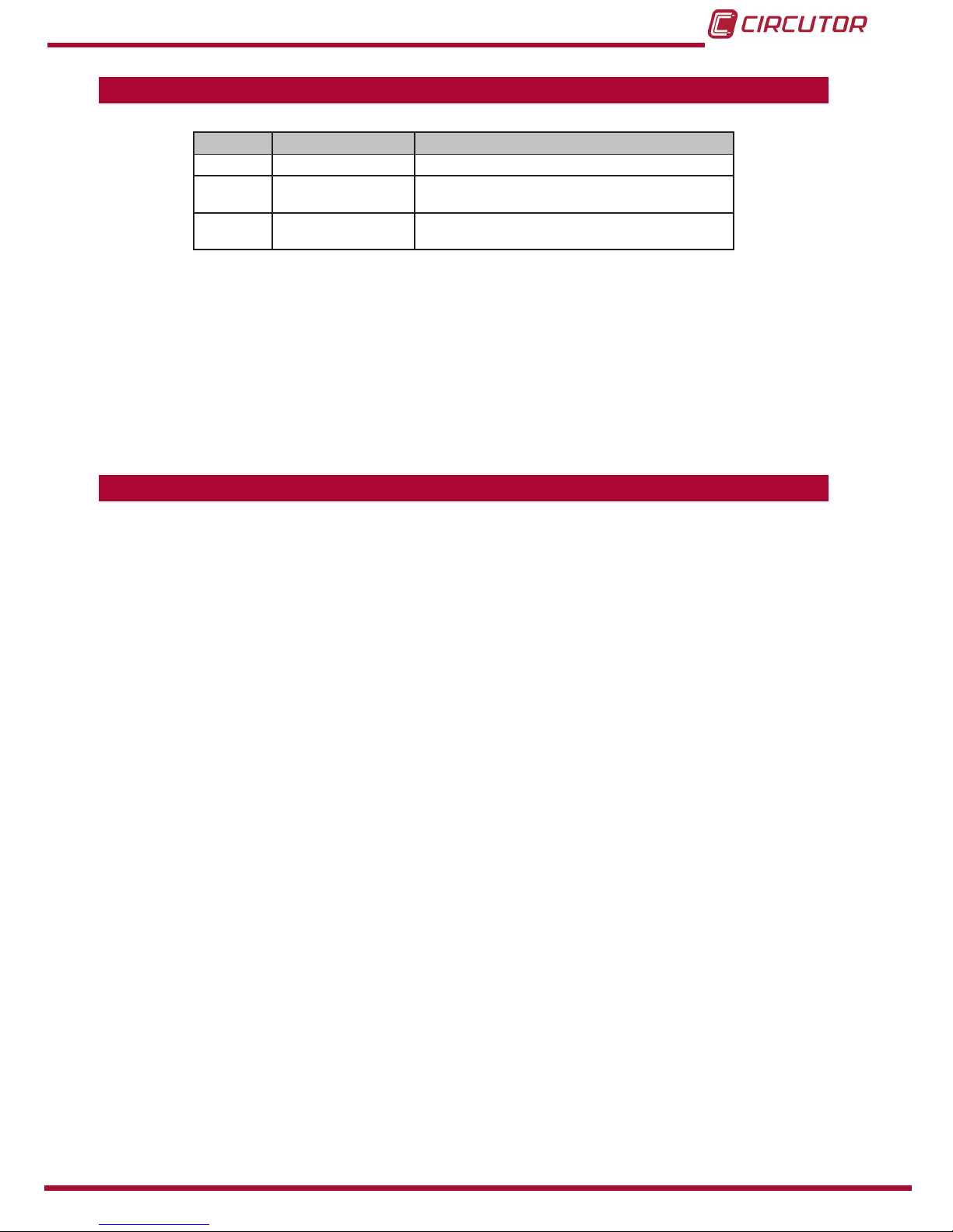
Table 1: Revision log�
Date Revision Description
10/15 M094B01-03-15A Initial Version
05/16 M094B01-03-16A
Changes to section:
3.2. - 3.6.3.- 4.4. - 4.6. - 5.
07/17 M094B01-03-17A
Changes to section:
2.- 3.3.1. - 3.7. - 3.8.1. - 3.8.2. - 4.1. - 4.7. - 4.8. - 5.
Note: The images of the devices are for illustrative purposes only and may differ from the orig-
inal unit.
INFORMATIVE NOTE
CIRCUTOR’s WB and eHome chargers range is designed for the recharge of electric vehicles
(VE) in Mode 3 in accordance with IEC-61851 (VE charging conductive system).
Given the current developments and continuous innovations in EVs, coupled with the emergence of new models, could be the case that the car manufacturer has incorporated new fea-
tures or modications not covered in the standard, thereby resulting in abnormalities during the
rst operations of recharge.
In case that the EV charger does not perform the recharge correctly or an error message appears, please contact the Technical Support Service of CIRCUTOR 902.449.459 or (+34)
937.452.919, to provide you with the most appropriate solution.
Page 6

6
eHome
Instruction Manual
1�- VERIFICATION UPON RECEPTION
Check the following points when you receive the device:
a) The device meets the specications described in your order.
b) The device has not suffered any damage during transport.
c) Perform an external visual inspection of the device prior to switching it on.
d) Check that it has been delivered with the following:
- User manual,
- 1 Cable gland M25x1.5,
If any problem is noticed upon reception, immediately contact the transport
company and/or CIRCUTOR’s after-sales service.
2�- PRODUCT DESCRIPTION
The eHome charging system is specially designed to be easily installed both in outdoor and indoor private car parks, in order to charge all the EV brands of the market in MODE 3 (according
to European standard IEC 61851-1), by just connecting either its tethered cable with a type 1
or type 2 connector.
The device features:
- Remote control input, allows to start/stop the EV recharge by means of a dedicated
logic input.
- Plug & Play, It is possible to start charging by just plugging the eHome connector into
the car.
- Current limitation, by means of an on-board rotative DIP switch, the maximum current
delivered by the unit is setup.
-Status RGB LED bar, It shows the status of the unit when it is either available or charg-
ing. Also some specic blinking error sequences are shown when there is a faulty operation.
- Housing, designed for outdoor and indoor operation.
Page 7
7
Instruction Manual
eHome
PENDIENTE DE VALIDACIÓN
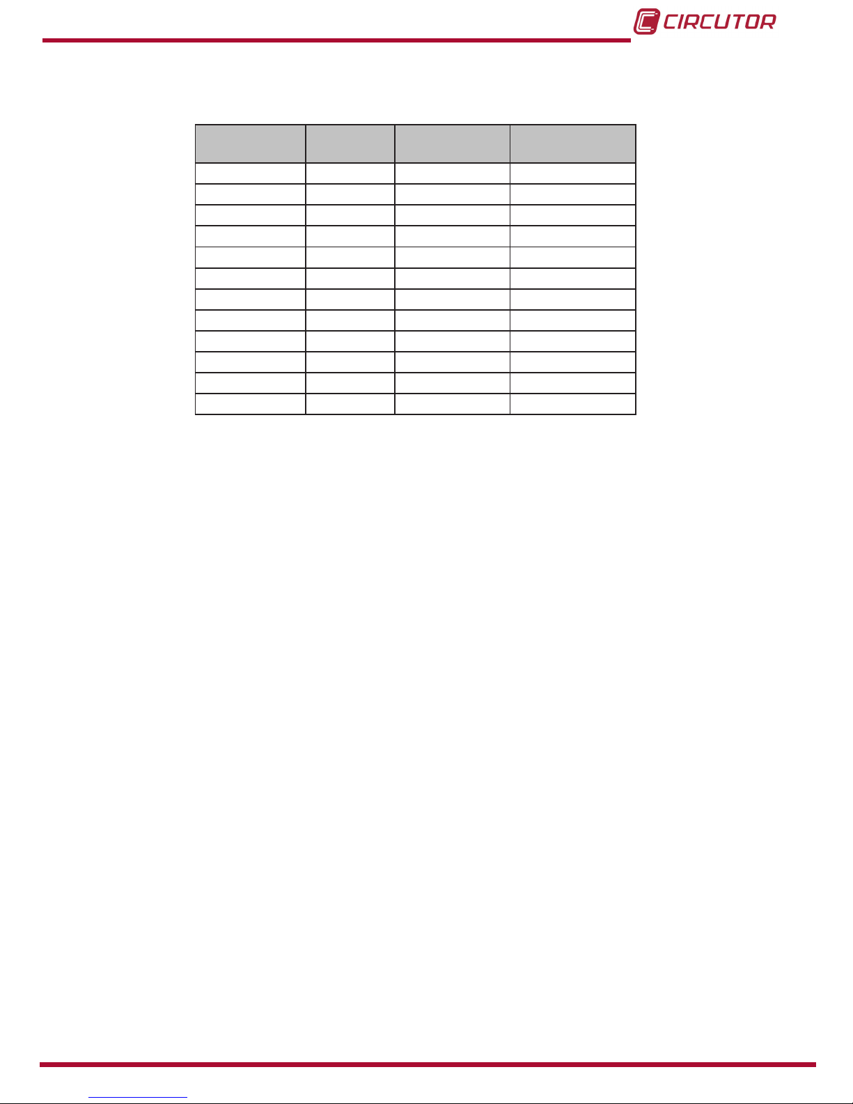
Table 2 shows all the devices in the eHome series.
Table 2:SeHome series�
Models Connector
Earth leakage
protection
MID meter
T1C16 Type 1 -
-
T1C32 Type 1 -
-
T2C16 Type 2 -
-
T2C32 Type 2 -
-
T1C32-A Type 1 Type A
-
T1C32-B Type 1 Type B
-
T1C32-A MID Type 1 Type A
T2C32-A Type 2 Type A
-
T2C32-B Type 2 Type B
-
T2C32-A MID Type 2 Type A
T1C16 N
(1)
Type 1 -
-
T1C32 N
(1)
Type 1 -
-
(1)
T1C16 N and T1C32 N models are approved by NISSAN with detection and protection in
case the output counter interlocks.
Page 8
8
eHome
Instruction Manual
3�- DEVICE INSTALLATION
3.1.- PRELIMINARY RECOMMENDATIONS
The device is designed for installation in indoor and outdoor areas. Whatever is the case, the
device must be installed safely and with the adequate electrical protections.
In order to use the device safely, it is essential that the individuals who handle
it follow the safety measures set out in the standards of the country where it is
being used.
The eHome device must be installed by authorised and qualied staff.
The eHome must not be installed in areas where there is a potential risk of explosions.
Do not install the device where falling objects may damage the equipment.
The wall surface where the device is placed must withstand the mechanical forces.
Do not use this device for anything other than electric vehicle charging modes which are expected in IEC 61851.
Do not make repairs or manipulations with the unit energised.
The manufacturer of the device is not responsible for any damage resulting from failure by the
user or installer to heed the warnings and/or recommendations set out in this manual, nor for
damage resulting from the use of products or accessories that did not come with the device or
that were made by other manufacturers.
Check the installation annually by qualied technician.
Remove from service any item that has a fault that could be dangerous for users (broken plugs,
caps that don’t close...).
Do not use this product if the enclosure or the EV connector is broken, cracked, open, or shows
any other indication of damage.
Disconnect the device from the power supply before maintaining, repairing or
handling the device’s connections.
Please contact the after-sales service if you suspect that there is an operational
fault in the device.
Do not modify this device.
The warranty will be void.
Page 9
9
Instruction Manual
eHome
PENDIENTE DE VALIDACIÓN
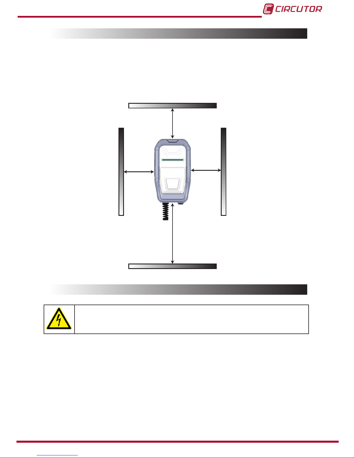
3.2.- EMPLACEMENT
When installing the unit it is necessary to respect some minimum distances for maintenance
and safety reasons.
The recommended LA height is :
Minimum value: 600 mm.
Maximum value: 1200 mm.
Please comply accordingly to your country specications.
300 mm 300 mm
300 mm
LA
Figure 1:Emplacement�
3.3.- ELECTRICAL WIRING
Before starting with the wiring connection of the charging station, you must take
into consideration this section.
3�3�1�- eHome POWER SUPPLY
Not all models include elements for electrical protection.
The power supply line which comes from the distribution board to the charging point, must meet
the electrical safety standards, according to your country regulations. The minimum safety re-
quired protections are as follows:
RCD: Type A. IΔN = 0.03 A.
Note: It is not necessary for models that already include protection internally: eHome
T2C32-A, T2C32-B, T2C32-A MID, T1C32-A, T1C32-B, T1C32-A MID.
Page 10

10
eHome
Instruction Manual
MCB: Its gauge must be chosen depending on the maximum output current of the
charging point.
For more information, see 5.- TECHNICAL FEATURES.
3�3�2�- POWER SUPPLY - LINE DIMENSIONING
The dimensioning of the device power supply line must be checked by a qualied electrician.
Note that various factors such as the cable length between the distribution board and the de-
vice, its maximum output current or ambient temperature may have inuence of the selected
cable.
So, it is important to select the appropriate cable cross-section in agreement with the local regulations and the power supply cable type that it is used.
3�3�3�- CHARGING POINT MAXIMUM OUTPUT CURRENT
If the installed device power supply is less than the maximum output current of the charge
point, an adjustment to a lower nominal current must be performed using the on-board rotative
dipswitch.
Note: Please refer to 4.5.- CURRENT LIMIT SELECTOR section in order to know how to change
this value.
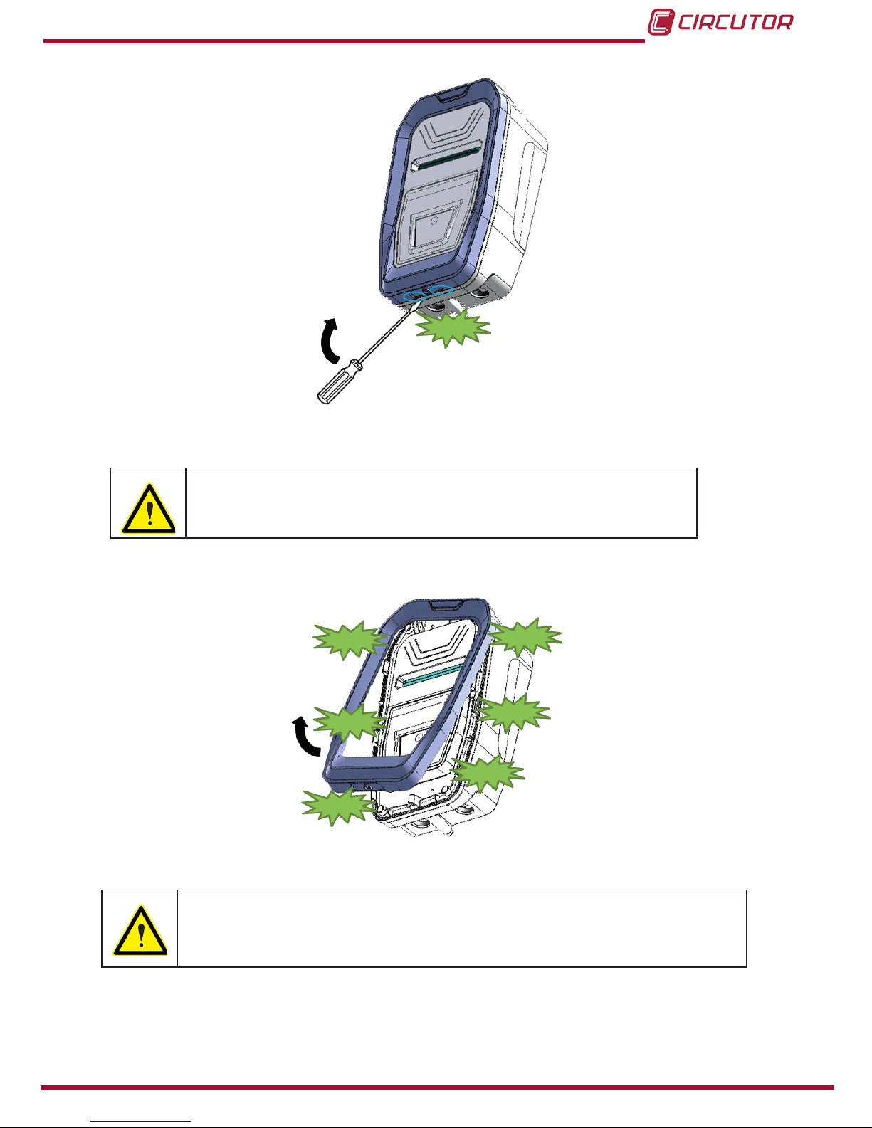
3.4.- OPENING THE DEVICE
1�- Remove the screw at the bottom of the box.
Figure 2: Opening the device, Step 1�
2�- Using a screw driver, put it into the indicated marks, at the bottom of the box, and start re-
moving the frame doing click at the bottom.
Page 11
11
Instruction Manual
eHome
PENDIENTE DE VALIDACIÓN
CLICK
Figure 3:Opening the device, Step 2�
Beware of not breaking the plastic of the frame with the screw driver.
3�- Grabbing the frame with the hand by the lower part, pull and take it off totally, from the bottom to the top.
CLICK
CLICK
CLICK
CLICK
CLICK
CLICK
Figure 4:Opening the device, Step 3�
To make it easier help yourself with the screw driver while pulling the frame off.
Page 12
12
eHome
Instruction Manual
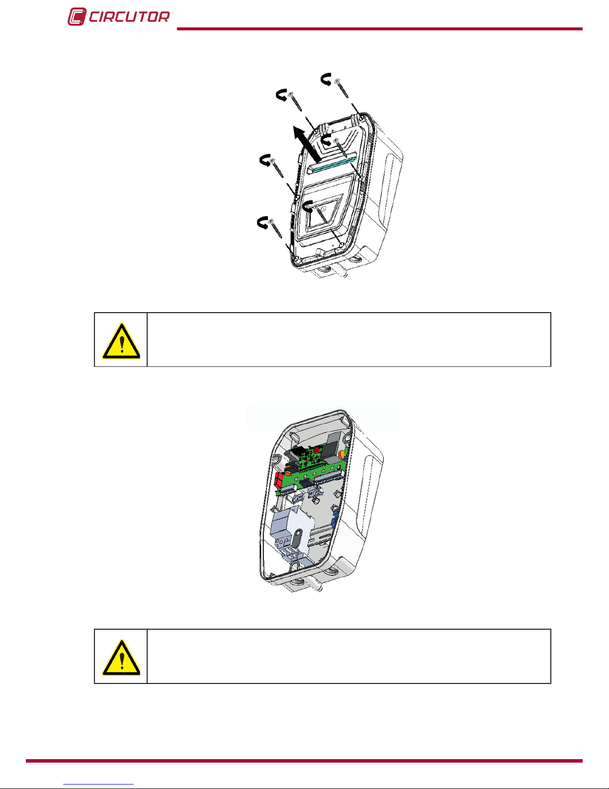
4�- Remove the six screws of the front part by using a screw driver and take out the front part
of the enclosure.
Figure 5:Opening the device, Step 4�
Be sure that the device is not energised before going forward with the opening
procedure.
5�- When the front part of the enclosure is off, you can access to the inside components of the
device.
Figure 6:Opening the device, Step 5�
Only the authorised and qualied staff can manipulate the electrical and electronic components of the device.
Page 13
13
Instruction Manual
eHome
PENDIENTE DE VALIDACIÓN
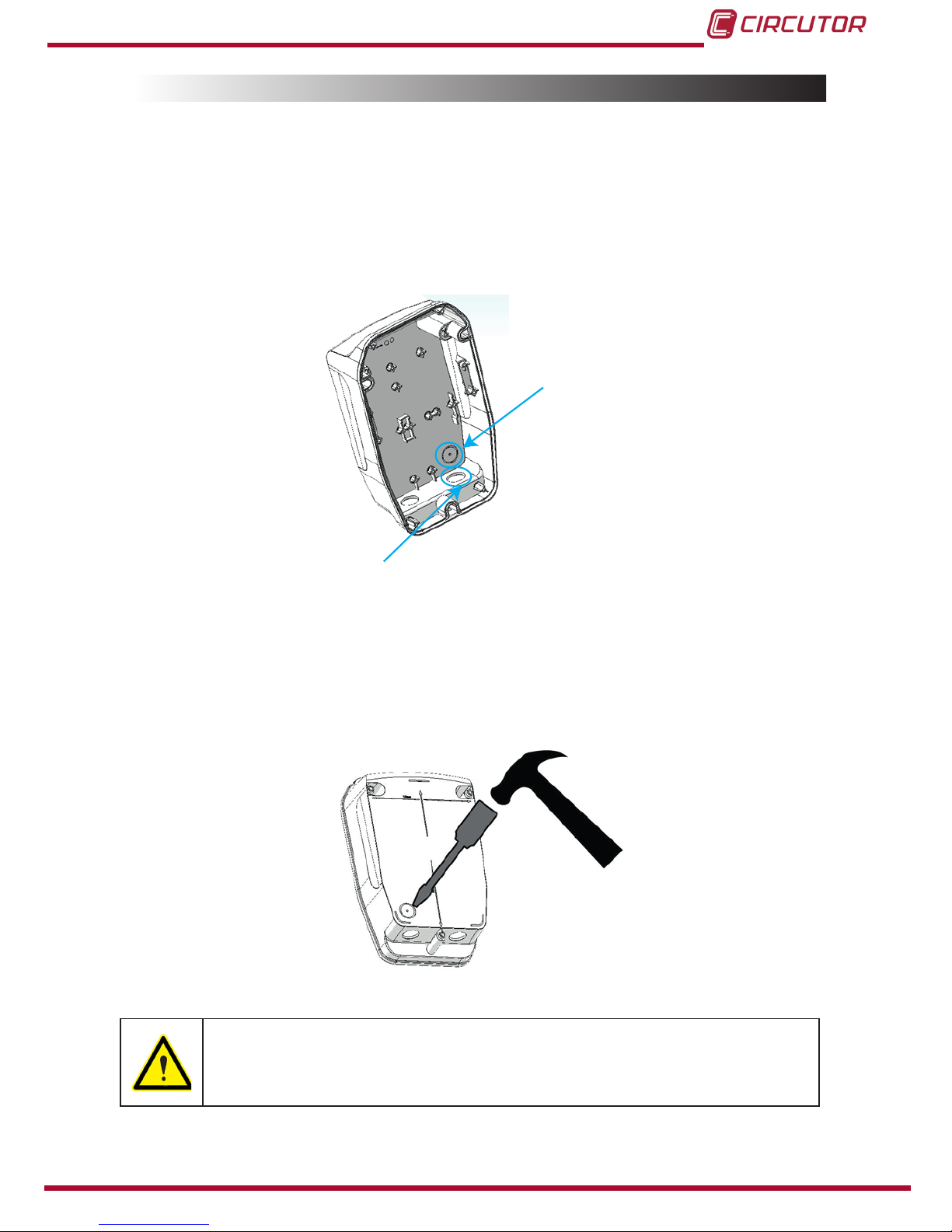
3.5.- POWER SUPPLY LINE CABLE INSERTION
There are two possibilities to insert the electric wires or electric pipe:
Using the rear cable insertion opening.
Using the bottom cable insertion opening.
In all cases it is required to install a cable gland to ensure properly installation and preserve the
IP of the device.
Rear cable insertion
opening
Bottom cable insertion
opening
Figure 7:Cable insertion opening�
3�5�1�- USING THE REAR CABLE INSERTION OPENING
Use a hammer and a athead screwdriver carefully in order to break out the cable insertion
opening, as shown in the picture below:
Figure 8:Rear opening�
Do not make any other holes on the enclosure. Use only the marked cable in-
sertion openings to install the required electric pipes.
Install always double membrane seals to ensure IP protection of the device�
Page 14

14
eHome
Instruction Manual
Be careful of not damaging any of the inside components when breaking out
the rear cable insertion opening.
3�5�2�- USING THE BOTTOM CABLE INSERTION OPENING�
Introduce the cable through the opening and x it properly by means of the supplied M25 cable
gland.
Figure 9:Bottom opening�
Note: The power supply cable must be 3x4mm2 (for the 16 A models) and 3x6mm2 (for the 32
A models) to meet the supplied cable gland.
Do not make any other holes on the enclosure. Use only the named cable in-
sertion opening to install the required electric pipes.
Install always either cable glands or double membrane seals to ensure IP
protection of the device�
3.6.- WALL FIXATION PROCEDURE
3�6�1�- NEEDED MATERIAL
Below, it is shown the list of materials (not included) that are necessary to x the device on the
wall:
Table 3:Needed material�
Material Quantity Dimensions Picture
Wall plug 3 Ø 6 mm
Screws 3 4x45 mm
Page 15

15
Instruction Manual
eHome
PENDIENTE DE VALIDACIÓN
All materials shown in the above table may vary depending on the wall surface
type.
3�6�2�- CONSIDERATIONS
The device is designed to drain the water properly from the upper side down.
The device must be installed vertically (use a level tool to ensure its installation at an angle of
90º)
Please ensure that the installation surface is at.
Figure 10:Considerations�
3�6�3�- INSTALLATION
1�- Adjust the vertical position of the charging point to ensure the correct vision and manage-
ment for the end user.
Figure 11:Installation, step 1�
Minimum recommended height: 600 mm
Please comply to your country specications.
2�- Mark 3 holes taking into account the Figure 12 (also written on the rear face of the box).
Page 16

16
eHome
Instruction Manual
238
158
Figure 12: Installation, step 2�
Place the enclosure on a at surface.
Use 3x45mm screws to x the unit to the wall.
Check whether the box has any inclination using a level tool.
3�- Use Ø 6 drill size to make the 3 holes into the wall.
Figure 13:Installation, step 3 (a)�
Install the anchor according to the surface material.
Figure 14:Installation, step 3 (b)�
4�- Use a screw driver to x the unit on the wall (recommended screw dimensions: 3x45mm)
Use only the device holes indicated in the Figure 15 to x the device on the wall. Do not make
any other holes on the housing; otherwise the water can enter the device when it rains.
Page 17

17
Instruction Manual
eHome
PENDIENTE DE VALIDACIÓN
Figure 15:Installation, step 4�
All screws and wall plugs needed to attach the device to the wall are not included.
3.7.- CABLE SUPPORT
The device has a support for the cable, Figure 16.
(Units in mm)
Figure 16: Cable support�
Table 4 shown the list of materials (not included) that are necessary to x the cable support on
the wall:
Page 18

18
eHome
Instruction Manual
Table 4:Needed material�
Material Quantity Dimensions Picture
Wall plug 3 Ø 6 mm
Screws 3 3x45 mm
All materials shown in the above table may vary depending on the wall surface
type.
3�7�1�- INSTALLATION
1�- Use Ø 6 drill size to make the 3 holes into the wall.
Figure 17: Installation, Step 1�
2�- Install the anchor according to the surface material.
Figure 18: Installation, Step 2�
3.8.- ELECTRICAL INSTALLATION
3�8�1�- POWER SUPPLY LINE PROTECTIONS
Not all models include elements for electrical protection.
Therefore, please connect a Miniature Circuit Breaker (MCB) and a Residual Current Device
(RCD) externally to protect the unit electrically, according to you country regulations.
Note: The RCD is not required for models that already include protection internally: eHome
T2C32-A, T2C32-B, T2C32-A MID, T1C32-A, T1C32-B, T1C32-A MID.
Page 19

19
Instruction Manual
eHome
PENDIENTE DE VALIDACIÓN
MCB RCD
Figure 19:Electrical installation, step 1�
The device is set to 16A / 32A, depending on the model, from factory default
settings.
3�8�2�- POWER SUPPLY LINE CONNECTION
Perform the 230V ~ single-phase connection as shown in the Figure 20.
Do not forget to connect the ground cable (PE) to its corresponding terminal.
L N PE
L N PE
Figure 20:Electrical installation, step 2�
Page 20

20
eHome
Instruction Manual
3.9.- CLOSING THE DEVICE
1�- Place back the 6 screws from the front cover in order to close the device.
Figure 21:Closing the device, step 1�
Beware of the cables between the cover and the base while closing the device.
2�- Put the frame back, from the top to the bottom of the box, ensuring it does click at the six
points shown in the Figure 22.
CLICK!
CLICK!
CLICK!
CLICK!
CLICK!
CLICK!
Figure 22:Closing the device, step 2�
Be sure that the frame is properly adjusted to the front cover in order to preserve the IP of the device.
Page 21

21
Instruction Manual
eHome
PENDIENTE DE VALIDACIÓN
3.10.- CHECKING THE DEVICE STATUS
Once all installation procedure has been performed, check the following points:
1�- Check that the EV tethered cable and its connector are in proper conditions before starting
the charging operation.
2�- Check that no abnormal noise appears while the device is charging.
3�- Check the status LED bar to know the present operating status of the device. Below you can
see the Table 5 with the four possible LED bar operating colors:
Table 5: Checking the device status�
State LED bar color
Available Green
Charging Blue ashing
Charged Blue
Fault Red ashing
Heating Orange
Note: For further information about the different status led bar sequences, please refer to 4.-
OPERATION section.
Page 22

22
eHome
Instruction Manual
4�- OPERATION
4.1.- PRODUCT DESCRIPTION
4�1�1�- eHome T1C16, T1C32, T2C16, T2C32, T1C16 N and T1C32 N MODELS
4�1�1�1� - Front product view
1
2
3
4
Figure 23: Front product view (eHome T1C16, T1C32, T2C16, T2C32, T1C16 N and T1C32 N)
Table 6: Front product view (eHome T1C16, T1C32, T2C16, T2C32, T1C16 N and T1C32 N)
Description
1 CIRCUTOR logo
2 Front cover
3 Status RGB LED bar
4 Frame
Page 23

23
Instruction Manual
eHome
PENDIENTE DE VALIDACIÓN
4�1�1�2�- Inside product view: eHome T1C16, T1C32, T2C16 and T2C32 Models
1
2
3
4 5
6
7
8
9
Figure 24: Inside product view (eHome T1C16, T1C32, T2C16 and T2C32)�
Table 7: Inside product view (eHome T1C16, T1C32, T2C16 and T2C32)�
Description
1 EV tethered cable
2 Output contactor
3 Main board
4 Current limit selector
5 Rear cover
6 RGB LEDs
7 Input terminals
8 Heater ( Optional depending on the model)
9 Power supply line
Page 24

24
eHome
Instruction Manual
4�1�1�3�- Inside product view: eHome T1C16 N and T1C32 N Models
1
2
3
4
5
6
7
8
9
10
11
Figure 25: Inside product view (eHome T1C16 N and T1C32 N)�
Table 8: Inside product view (eHome T1C16 N and T1C32 N)�
Description
1 EV tethered cable
2 Output contactor
3 Main board
4 Current limit selector
5 Rear cover
6 RGB LEDs
7 Input terminals
8 Heater ( Optional depending on the model)
9 Power supply line
10
Protection in case the output counter interlocks.
11 Trigger
Page 25

25
Instruction Manual
eHome
PENDIENTE DE VALIDACIÓN
4�1�2�- eHome T1C32-A, T1C32-B, T1C32-A MID, T2C32-A, T2C32-B AND T2C32-A MID
MODELS
4�1�2�1�- Front product view
1
2
3
4
5
6
Figure 26:Front product view (eHome T1C32-A, T1C32-B, T1C32-A MID, T2C32-A, T2C32-B, T2C32-A MID)
Table 9: Front product view (eHome T1C32-A, T1C32-B, T1C32-A MID, T2C32-A, T2C32-B, T2C32-A MID)
Description
1 CIRCUTOR logo
2 Front cover
3 Status RGB LED bar
4 Frame
5 Front door with key lock
6 Protection devices
Page 26

26
eHome
Instruction Manual
4�1�2�2�- Inside product view: eHome T1C32-A and T2C32-A models
1
2
3
4
5
8
9
6
7
10
Figure 27:Inside product view (eHome T1C32-A and T2C32-A)�
Table 10: Inside product view (eHome T1C32-A and T2C32-A)�
Description
1 EV tethered cable 6 RGB LEDs
2 Output contactor 7 Input terminals
3 Main board 8 Heater (Optional depending on the model)
4 Current limit selector 9 Power supply line
5 Rear cover 10 RCD type A
Page 27

27
Instruction Manual
eHome
PENDIENTE DE VALIDACIÓN
4�1�2�3�- Inside product view: eHome T1C32-A MID and T2C32-A MID models
1
2
3
4
5
8
9
6
7
10
11
Figure 28:Inside product view (eHome T1C32-A MID and T2C32-A MID)�
Table 11: Inside product view (eHome T1C32-A MID and T2C32-A MID)�
Description
1 EV tethered cable 7 Input terminals
2 Output contactor 8 Heater (Optional depending on the model)
3 Main board 9 Power supply line
4 Current limit selector 10 RCD type A
5 Rear cover 11 Energy meter
6 RGB LEDs
Page 28

28
eHome
Instruction Manual
4�1�2�4�- Inside product view: eHome T1C32-B and T2C32-B
1
2
3
4
5
8
9
6
7
10
Figure 29:Inside product view (eHome T1C32-B and T2C32-B)�
Table 12: Inside product view (eHome T1C32-B and T2C32-B)�
Description
1 EV tethered cable 6 RGB LEDs
2 Output contactor 7 Input terminals
3 Main board 8 Heater (Optional depending on the model)
4 Current limit selector 9 Power supply line
5 Rear cover 10 RCD type B
Page 29

29
Instruction Manual
eHome
PENDIENTE DE VALIDACIÓN
4.2.- FIRMWARE VERSION
When the device is booting, the LED bar will show the rmware version in orange.
The rst digit of the version will be shown as a certain number of blinkings of the rst LED, as
many times as the digit indicates, and the second digit will be displayed by the last LED blinking
accordingly to what the second digit indicates (i.e. for version 1.6, you will see one blink at the
rst LED and six at the last LED).
Figure 30:Firmware version�
4.3.- CHARGING PROCEDURE
1�- When the status LED bar is in green colour, it means that the device is available and ready
to start a recharge (A status)*�
(1)
.
Figure 31:The device is available to start a recharge�
2�- To start a new recharge, plug the eHome cable into your car.
3�- The status LED bar turns into blue. And the eHome starts the charging process.
While charging the EV, the LED bar will be ashing continuously (status C)
(1)
.
Page 30

30
eHome
Instruction Manual
Figure 32:Charging process�
4�- When the EV is fully charged, the charging process ends up and the status LED bar stops
ashing and keeps x in blue (B status)
(1)
.
Figure 33:The EV is fully charged�
Then you can unplug the cable from the EV.
5�- Once the cable is disconnected from the EV, the LED status bar turns back into green (A
status)
(1)
.
In this status, the unit is available to start a new charging process, whenever it is required.
(1)
According to IEC 61851.
Page 31

31
Instruction Manual
eHome
PENDIENTE DE VALIDACIÓN
4.4.- OPERATING ERROR DETECTION
The eHome is capable to detect the following operating errors:
Ventilation required error.
Pilot error.
Proximity error.
Negative PWM error
Maximum output current DIP switch error.
Temperature error.
Whatever the error case is, the unit will stop charging and technical assistance will be required,
except from the temperature error. In this last case, the unit starts charging when the operating
temperature is reached again.
In the Table 13 it will be explained how the eHome shows the above mentioned errors and the
actions taken by the device.
Table 13: Operating errors�
Error LEDs bar
Ventilation required error (D status)
(1)
In some old EVs, this state means that there are some gases coming out from the batteries. So, an external ventilation in the car park
might be required.
Red, 1 blink
sequence
Pilot error ( E status)
(1)
When the device is connected to the EV, a Pilot short-circuit to eath
may occur.
Red, 2 blink
sequence
Proximity error
When the device is connected to the EV, a Proximity short-circuit to
earth may occur.
Red, 3 blink
sequence
Negative PWM voltage error
When the device is connected to the EV, the PWM signal, used to
communicate the device with the EV, can be negative.
Red, 4 blink
sequence
Maximum output current DIP switch error
If this on board current limit selection is not setup according to the
hardware features, the device detects it and shows this error.
Red, 5 blink
sequence
Page 32

32
eHome
Instruction Manual
Tabla 13 (Continuation) : Operating errors�
Error LEDs bar
Temperature error
When the device temperature is below or above a certain value, it is
detected by the device.
In the meantime, if the device is supplied with heater (optional), it
starts heating the inside components until the operating temperature
is reached. Then the device starts charging again.
Orange, blink
sequence
(1)
According to IEC IEC 61851.
4.5.- CURRENT LIMIT SELECTOR
There is an onboard rotative DIP switch to congure the limit current of the device, which has to
be set up according to the model of Wallbox eHOME we are going to install.
Be sure that the position of the current limit selector is setup according to the
output current of your device.
Figure 34:DIP switch�
On the Table 14 is shown the different values available for this current limit selector:
Table 14: DIP switch, position
Position Limit current Position Limit current
0 Not used 5 20 A
1 6 A 6 32 A
2 10 A 7 Not used
3 13 A 8 Not used
4 16 A 9 Not used
Page 33

33
Instruction Manual
eHome
PENDIENTE DE VALIDACIÓN
4.6.- REMOTE CONTROL INPUT
The eHome series offer the possibility of enabling the charging process by connecting an external free-of-potential contact to a dedicated on-board input between pins 4 and 5 (see below
Figure 35).
Figure 35:Remote control input�
This way, when the contact START is closed, if the EV is connected to the device, it will start
the recharge straight away.
This remote control input is enabled by default, by means of a jumper (Figure 36).
You must remove the jumper to use the input 4-5.
Figure 36:Jumper�
Be sure that the jumper is connected by default, otherwise the charging process cannot start.
Page 34

34
eHome
Instruction Manual
4.7.- RESIDUAL CURRENT (eHome TxC32-A, - B, -A MID models)
Note: Residual current is only available on models: eHome T1C32-A, T1C32-B, T1C32-A MID,
T2C32-A, T2C32-B y T2C32-A MID.
4�7�1�- RESET THE RESIDUAL CURRENT DEVICE
The Residual-Current Device (RCD) installed in the different eHome models must be reset in
case of actuation.
To reset the Residual-Current Device (RCD), previously, it is needed to check the possible
electrical risk for the user.
1�- Beware the eHome is disconnected to the power line. And similarly, the unit must be disconnected by the Miniature Circuit Breaker (MCB) of the power line.
2�- Beware the Vehicle is not connected to the device.
3�- Check the status of the cable and the plug of the device.
4�- Check the plug, not being in contact with wet surface of directly with water.
5�- After checking the possible damages of the cable and the plug of the device with its possible
contact with water. It is necessary to check that the cable and the plug have no suffered any
damage of overcurrent.
During the RCD reset operations, it must be checked the properly status of the
cable and plug, not being dirty or damaged, and likewise, not having wet surfaces close to the device.
6�- After the properly checked of the previous points, it is possible to make the reset in the RCD
Figure 37: RCD type A and RCD type B
Note: Once it has been made the properly checked of the points exposed before, and it is
not possible to reset the RCD. It will be necessary to disconnect the unit and call for a correct
trained, qualied and authorized technician.
Page 35

35
Instruction Manual
eHome
PENDIENTE DE VALIDACIÓN
4�7�2�- MAINTENANCE OF RESIDUAL-CURRENT DEVICE (RCD)
For the properly performance of the RCD in the different models of eHome, the RCD must be
checked once a month.
For making this operation, it is necessary to push the Test button (indicated as a “T” in the same
RCD).
By this way, it will be feasible to see if the RCD is working properly.
Figure 38: Test button in the RCD�
If there is no any action by the RCD after pressing the button, the RCD is NOT working properly,
and in consequence it is necessary to replace the RCD.
4�7�3�- ENERGY METER
The energy meter counts the total energy consumed incrementally from the point of commissioning. Therefore, it shows the value during the total lifetime of the meter.
Figure 39:Energy meter�
Page 36

36
eHome
Instruction Manual
4.8.- CirBEON (Optional)
The CirBEON is an optional device that can optimize the Electric Vehicle (EV) Charger. It is
the responsible to analyze the total current consumption in the residential, and to manage the
remaining current for the EV Charger, avoiding any tripping the Main Circuit Breaker (MCB) for
overconsumption.
CirBEON product range, Table 15:
Table 15: BeON range�
Range Range
20 A 4.6 kW 40 A 9.2 kW
25 A 5.75 kW 50 A 11.5 kW
30 A 6.9 kW 63 A 14.49 kW
35 A 8.05 kW
Only the authorised and qualied staff can manipulate the electrical and electronic components.
• Comply strictly with electrical safety regulations according to your country.
• Do not make repairs or manipulations with the unit energised.
• Only trained and qualied personnel should have access to low-voltage electrical parts inside the device.
•Use only CIRCUTOR supplied spare parts.
4�8�1�- LEDs BAR STATUS CONSIDERATION
All the LEDs of the status LED bar turns into blue ashing when there is no enough current to
charge the EV, when there is enough current, the system is re-establishing the charging process automatically
Figure 40: No enough current to charge the EV�
Page 37

37
Instruction Manual
eHome
PENDIENTE DE VALIDACIÓN
4�8�2�- CONNNECTIONS CirBEON
1
10
10
11
11
4 5
3
6
2
7
8
9
Figure 41: Connections of CirBEON�
Table 16: Connections of CirBEON�
Description
1 EV tethered cable 7 Input terminals
2 Output contactor 8 Heater ( Optional depending on the model)
3 Main board 9 Power supply line
4 Current limit selector 10 Pin 2S1, CirBEON negative
5 Rear cover 11 Pin 2S2, CirBEON positive
6 RGB LEDs
Page 38

38
eHome
Instruction Manual
5�- TECHNICAL FEATURES
AC input
Model
T1C16
T1C16 N
T1C32
T1C32 N
T1C32-A
T1C32-B
T1C32-A MID
T2C16
T2C32
T2C32-A
T2C32-B
T2C32-A MID
AC Power supply 1P + N + PE
AC Voltage 230 V ~ ± 10%
Nominal input current
16 A 32 A 16 A 32 A
Nominal input power 3.7 kW 7.4 kW 3.7 kW 7.4 kW
Frequency
50/ 60 Hz
Output
Model
T1C16
T1C16 N
T1C32
T1C32 N
T1C32-A
T1C32-B
T1C32-A MID
T2C16
T2C32
T2C32-A
T2C32-B
T2C32-A MID
Charge system Mode 3
Sockets/ Plugs Type 1 cable Type 2 cable
Cable length 5 m.
Lock system No
Maximum output power 3.7 kW 7.4 kW 3.7 kW 7.4 kW
Maximum output current 16 A 32 A 16 A 32 A
Output voltage range 230V~ (1P + N + PE)
CirBEON (Optional)
Type Current transformer Ring core
Rated insulation level 0.72 / 3 / - kV
Relation 25/0.05 A, 30/0.05 A, 35/0.05 A, 40/0.05 A, 50/0.05 A, 63/0.05 A
Accuracy Class I
Connection 2S1 (-), 2S2 (+)
Current direction P1 ↓
Maximum cable length
200 m
Cable cross-section 1 mm
2
Protection degree IP20
Material Poliester
Dimensions 30 x 15 mm
Environmental features
Operating temperature -5ºC ... +50ºC
Temperatura de trabajo extendido (Heater optional) -30ºC ... + 50ºC
Relative humidity (with no condensation) 95%
Protection degree IP54 / IK10
Mechanical features
Dimensions (mm) Figure 42
Weight 4 kg.
Enclosure ABS-PCV0
Page 39

39
Instruction Manual
eHome
PENDIENTE DE VALIDACIÓN
Figure 42: Dimensions�
Standards
Electric vehicle conductive charging system - Part 1: General requirements IEC 61851-1:2010
Electric vehicle conductive charging system -- Part 22: AC electric vehicle
charging station
IEC 61851-22: 2001
Plugs, socket-outlets, vehicle connectors and vehicle inlets - Conductive
charging of electric vehicles - Part 1: General requirements
IEC 62196-1:2014
Plugs, socket-outlets, vehicle connectors and vehicle inlets - Conductive
charging of electric vehicles - Part 2: Dimensional compatibility and interchangeability requirements for a�c� pin and contact-tube accessories
IEC 62196-2:2011
Directives: 2014/35/UE, LVD; 2014/30/UE, EMC
Page 40

40
eHome
Instruction Manual
6�- MAINTENANCE AND TECHNICAL SERVICE
7�- GUARANTEE
• No returns will be accepted and no unit will be repaired or replaced if it is not ac-
companied by a report indicating the defect detected or the reason for the return.
•The guarantee will be void if the units has been improperly used or the storage, installation and maintenance instructions listed in this manual have not been
followed. “Improper usage” is de ned as any operating or storage condition con-
trary to the national electrical code or that surpasses the limits indicated in the
technical and environmental features of this manual.
• CIRCUTOR accepts no liability due to the possible damage to the unit or other
parts of the installation, nor will it cover any possible sanctions derived from a pos-
sible failure, improper installation or “improper usage” of the unit. Consequently,
this guarantee does not apply to failures occurring in the following cases:
- Overvoltages and/or electrical disturbances in the supply;
- Water, if the product does not have the appropriate IP classi cation;
- Poor ventilation and/or excessive temperatures;
- Improper installation and/or lack of maintenance;
- Buyer repairs or modi cations without the manufacturer’s authorisation.
CIRCUTOR
guarantees its products against any manufacturing defect for two years after the
delivery of the units.
CIRCUTOR will repair or replace any defective factory product returned during the guarantee
period.
In the case of any query in relation to unit operation or malfunction, please contact the
CIRCUTOR, SA Technical Support Service.
Technical Assistance Service
Vial Sant Jordi, s/n, 08232 - Viladecavalls (Barcelona)
Tel: 902 449 459 ( España) / +34 937 452 919 (outside of Spain)
email: sat@circutor.com
Page 41

41
Instruction Manual
eHome
PENDIENTE DE VALIDACIÓN
Page 42

CIRCUTOR, SA
Vial Sant Jordi, s/n
08232 - Viladecavalls (Barcelona)
Tel: (+34) 93 745 29 00 - Fax: (+34) 93 745 29 14
www.circutor.com central@circutor.com
 Loading...