

Page 1
EDMk Manual
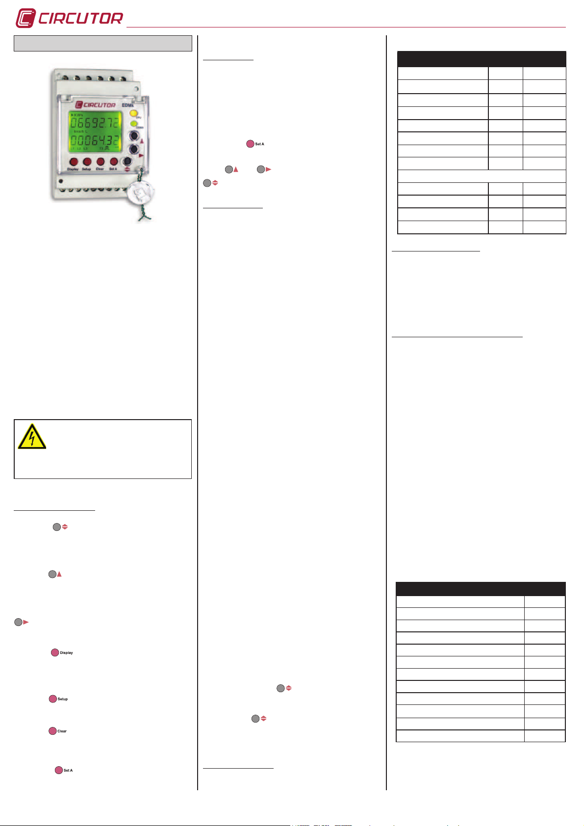
THREE PHASE METER EDMK
The EDMk three-phase electronic energy meter is capable
of me as ur in g co ns um ed a nd g en er at ed ene rg y (fou r
quadran ts) : Active energy (consumed an d generated),
inductive reactive energy (consumed and generated) and
capacitive reactive energy (consumed and generated), plus
metering partial energies.
Measurements are in true effective value, via three AC.
voltage and neutral inputs and three AC. current inputs. (via
…/5A, …/1A or .../250mA for MC3 current transformers).
The parameters measured and calculated are shown in
the variables table
This manual describes how to configurate and use the
ED Mk ene rgy meter. This man u al may b e f oun d i n
electronic format on the CIRCUTOR website:
www.circutor.com
Before any m ai nt en ance, modif ic at io n to
the connections, repair, etc., the equipment
must be disconnected from the supply. If any
operation or protection fault is suspected the
equipment must remain out of service ensuring against
any accidental reconnection. The equipment is designed
to changed quickly in the event of any breakdown
1. KEYBOARD FUNCTION.
The butto n allows the user to move through the
different energy groups (if any): tariff one and partial tariff,
or tariff one, two, three and partial tariff (EDM3k type). It
used in the set up menu it is used to enter the data and
move on to the next parameterisation screen.
The button allows the active or reactive energy display
options to be displayed. It is used in the set up menu
to increase the value by one digit if a variable has been
entered or selected.
Generated or consumed energy can be selected using
in the option. Inductive or capacitive energy can be
selected in the reactive option. In the set up menu is used
to move the cursor among the digits.
The button allows the display to come on in the
absence of any power supply. This function allows the on
site reading of meters when the device is out of service.
This option is available when the meter has an optional
station installed inside (see price list M3).
The button allows a quick access to the device’s full
parameterisation menu. To access this menu, press the
button for less than one second.
The button deletes partial energies. To do this, press
the button for less than 4 seconds. The message will then
display “donE”, indicating that these meters have been
successfully started (active and reactive).
Th e b ut t on
sta r ts the m ete r i n o ne ste p onl y
wit h the mini mu m setting for the m et er. (see s ec ti on
Parameterisation in one step only).
2. STARTING UP
2.1. Previous information
2.2. Parameterization in one step only
Thi s option is only valid for installat io ns wh er e there
is no vol tage transfor mer to meas ure. Voltage is only
measured directly (300V AC f-N / 500V AC f-f) and current
measurement is via secondary external current transformers
of .../1A, .../5A or in model MC of .../250 mA.
Kee pi ng th e
butt on pres se d for 1 seco nd , the
energy meter enables the current primary and secondary
parameterisation on screen.
Usi ng and but to ns the v alue of th e current
transformer primary and secondary is validated using thel
button.
3. COMPLET MENU
Using the complet e parameteris ation of the mete r, all
setting options can be set. These options affect the setting
of the external voltage transformers, if any, as well as the
omission of energy meters which the customer believes to
of little relevance or are not required in their installation.
3.1. Voltage transformer
On screen the words “Pri U” appear followed by 6 digits.
Thes e allow the volta ge transformer primary to be set
(from 1 to 999.999).
On screen the words “SEC u” appear followed by 3 digits.
These allow the voltage transformer secondary to be set
(from 1 to 999).
3.2. Current transformer
On screen the words “Pri A” appear followed by 4 digits.
These allow the current transformer primary to be set (from
1 to 9.999).
On scree n the wo rds “SEc A” appea r followed by the
number 5 or 1. These allow the installed current transformer
secondary ratio to be set (5 =…/ 5A or 1 =…/ 1A).
* The option secondary in model MC does not exist (is
allways 250mA)
3.3. Measurement in 2 or 4 quadrants
On scre en the word s “QuA d” appear; on e of th e two
available options must be selected: 2 = power consumption
or 4 = consumption and generation.
3.4. Backlight disconnection time setting
On s cre en the words “diSP oF f” appear; the time the
backlight is on can be set after pressing the keypad. The
backlight is permanently on if 00 is set.
3.5. Display or not reactive energy
On screen the words “rEACt” appear; this option allows the
reactive energy to be displayed or omitted (“YeS” or “nO”).
3.6. Display partial energy counters
On screen the words “PArt” appear; this option allows the
partial active and reactive energy to be displayed or omitted
(“YeS” or “nO”). In the event of omission, the meter does
not show energy and stops metering energy.
3.7. Energy output pulse settings
The screen shows “Out ACt”; the energy to be associated
to digit al output 1 must be s elected: Consu med active
energy (import) or generated (export); once the data
has been entered with button, the W•h value must
be entered by pressing.The screen shows “Out rEA”: the
reactive energy to be associated to digital output 2 must be
selected: L / C- / L- / C; once the data has been entered
with the button , the var•h value must be entered by
pressing the keypad. In case of selecting 2 quadrants (see
section 3.3. Measurement in 2 or 4 quadrants), only are
available L or C.
4. DEFAULT SETTINGS
The EDMk-ITF-C2 electronic three-phase meter is supplied
with the following default settings:
VARIABLE POINT VALUE
Primary voltage 3.1 000001
Secondary voltage 3.1 001
Primary current 3.2 0005
Secondary current 3.2 5 / 0.250 A
Measure in 2 or 4 quadrants 3.3 2
Backlight disconnection 3.4 10
Reactive energy display 3.5 no
Partial energy counters 3.6 no
Energy pulses
- Active energy 3.7 IMPORT
- w·h / pulse 3.7 1000
- Reactive energy 3.7 L
- var·h / pulse 3.7 1000
5. TARIFFS (EDM3K MODEL)
Th e t ari ff tim e i s c arr ied out using har dwa re. T he
equipment has a common and two inputs free of voltage
to select the type of tariff required (Tariff 1, Tariff 2 or Tariff
3).
- Tariff 1: Without any bridge between terminals
- Tariff 2: Bridge between terminal A and S
- Tariff 3: Bridge between terminal B and S
6. COMMUNICATIONS (RS-485 C2 MODEL)
6.1. Programming parameters
Confi gurable parameters in the parameterisation menu:
- “nPEr”: Peripheral number 001 to 255
- “bAud”: Baud rate 1200-2400-4800-9600-19200
- “bitS”: Length 8 bits
- “PAri”: No, Even, Odd
- “StoP”: Stop bits 1 or 2
Default settings 001 / 9600 / 8 / N / 1
6.2. Communication protocol
The EDMk meter uses MODBUS RTU © communication
protocol and network protocol RS-485. The format is as
follows:
QUESTION: NP FT AAAA NNNN CRC
NP: 1 Byte Peripheral number
FT: 1 Byte Function 04 reading of n Words
AAAA: 2 Bytes Address of 1st register
NNNN: 2 Bytes Number of regiters to be requested
CRC: 1 Byte Cyclic Redundancy Checking
In the MODBUS © recordings, the energy is accumulated in
kW•h x 100 (2 decimal points) with a length of 2 Words.
6.3. Modbus/RTU © memory map
PARAMETER REGISTER
Active Energy (+) 00-01
Active Energy (-) 02-03
Inductive reactive energy (+) 04-05
Capacitive reactive energy (-) 06-07
Inductive reactive energy (-) 08-09
Capacitive reactive energy (+) 0A-0B
Partial active energy (+) 30-31
Partial activ energy (-) 32-33
Partial inductive reactive energy (+) 34-35
Partial capacitive reactive energy (-) 36-37
Partial inductive reactive energy (-) 38-39
Partial capacitive reactive energy (+) 3A-3B
M98204801-03-11A
The device has to be provided of an magnetic-thermal
switch to be disconnected. The fuses has to be type gl
(IEC 269) or type M between 0,5 to 2 A.
6.4. Communications connections
De s cri p t ion of c o nne c t ion for the RS -48 5 bus , for
communication via an Intelligent Converter (485-RS232), or
via an Ethernet Converter (Transparent / Modbus/TCP).
Page 2
6.5. Communications description
One or more EDMk meters can be connected to a computer or PLC. As well as the usual operation of each piece of
equipment, this system may centralize data at one single point. The EDMk has an RS-485 series communications
output. If more than one analyzer is connected to one RS-485 communication bus, it is necessary to assign to each a
peripheral address (from 01 to 255) so that the remote computer or PLC sends data on different measured or calculated
recordings to those addresses. The RS-485 connection is made with woven mesh shielded communications cables,
with a minimum of three wires and with a maximum distance between remote computer and the last analyzer of 1.200
metres. This RS-485 series bus can connect up to a maximum of 32 devices.The EDMk meter communicates using the
MODBUS RTU© protocol (Pulling Question / Answer).
7. DISPLAY / LEDS
- L1-, L2- and L3- shows that the device has measured voltage in each phase. If one of these does not exist, the corresponding identifi cation number does not
appear. The symbols appearing behind each phase (L) indicate the direction of the current in the current transformers, showing if the point of measurement
is consuming or generating energy ( L1, L2 and L3 fl ashing, informs of possible errors of connection of current transformers).
- T1, T2 y T3 (identifi cation only available on the EDM3k; shows the tariff selected for that time, independently from the tariff displayed on the upper
section.
- The
symbol indicates that load is inductive. The symbol indicates a capacitive load.
- The symbol shows that the meter is the fi rst and fourth quadrant (consumption). The symbol indicates that the meter is in the second and third
quadrant (generation).
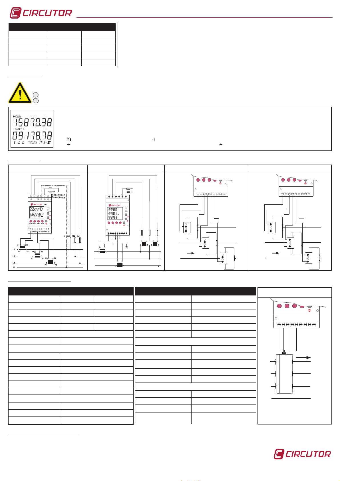
8. CONNECTIONS
9. TECHNICAL CHARACTERISTICS
EDMk-ITF-RS485-C2 Intelligent converter Ethernet converter
M31751 M54020 M54031 / M54032
BORNES RS-485 BORNES RS-485 RS-485 / RS-232
A (+) 1 (A( A
B (-) 2 (B) B
S (GND) 5 (GND) S
10. TECHNICAL ASSISTANCE SERVICE
In the event of any equipment failure or any operational queries please contact the technical service of CIRCUTOR, SA.
CIRCUTOR, SA. – After sales service.
Vial Sant Jordi s/n
08232 Viladecavalls, Barcelona
EDMk Manual
M98204801-03-11A
Tel.: (+34) 93 745 29 00
Fax: (+34) 93 745 29 14
e-mail: sat@circutor.es
3 or 4 wires (low voltage) 3 wires (2 VT y 2 CT) MC1-20 (example 200A) MC1-30 (example 500 A)
L1
L2
L3
min
maxPdN
max
clear
COMM
CPU
CVM-MINI
resetN Nreset energyN
123456789
101112131415
b
B
a
A
b
B
a
A
VL1
VL2
V
L3
S2
P2
S1
P1
S2
P2
S1
P1
POWER SUPPLY TIPO C.A. TIPO C.C. & C.A.
Single phase 230 V a.c. 85..265 Va.c./ 95...300 Vd.c
Voltage tolerance -15 %... +10 %
Frequency 45...65 Hz 0...65 Hz
Maximum burden 5 V·A
Operating temperature -20 ºC...+60 ºC -20 ºC...+60 ºC
Humedity (without condensation) 5 %...95 %
Maximum altitude 2.000 m
MECHANICAL FEATURES
Casing material Self extinguishing VO plastic
Protection assembled device (front) IP 51
Protection non assembled device IP 31
Supply and voltage measure wires Minimum section 1 mm²
Secondary current transformers wires Minimum section 2,5 mm²
Dimensions (mm) 85 x 52 x 70 (3 steps)
CLASS
Acuracy class in active energy Class 1 - EN62053-21
Accuracy class in reactive energy Class 2 - EN62053-23
STANDARDS
EN62052-11, EN62053-21, EN62053-23, EN61010-1
MEASUREMENT CIRCUIT
Rated voltage 300 V a.c. f-N / 500 V a.c. f-f
Frequency 45...65 Hz
Rated current .../5 or .../1
Permanent overload 1,2 In
Voltage circuit burden per phase 0,3 V·A
Current circuit burden per phase 0,3 V·A at 5 A. ó 0,06 V·A at 1 A
PULSE OUTPUT TRANSISTOR FEATURES
Opto-insulated transistor (open collector) NPN
Maximum operating voltage 24 V c.c.
Maximum operating current 50 mA
Maximum frequency 5 imp / s
Pulse length 50 ms
TRANSISTOR OUTPUTS CONNECTIONS
Output 1 Terminal 9 - 8
Output 2 Terminal 7 - 8
MAXIMUM COUNTER VALUE
9999999 kW
SAFETY
Ca teg ory III E N6101 0-1 . Clas s II do ubl e
insulation against electric shock.
TYPE MC3
The EDMk energy meter display is divided into two sections: the fi rst of these (on the upper section) displays the value of the energy meters (Active energy and Inductive
reactive energy or Capacitive). The second shows the measurement, in real time, being taken by the meter at that time.
CPU
CPU led indicates that the device is working right fl ashing in one second intervals.
COMM
COMM led fl ashes quickly in varible intervals when the device is receiving or sending information throught is RS-485 port.
Set ANS
DisplayND
NSSetup
ClearNC
1 2 3 4 5 6 7 8 9
L1
L2
L3
N
1P1
2P1
3P1
1P2
2P2
3P2
COM
2S1
L1
L2
L3
N
1P1
2P1
3P1
1P2
2P2
3P2
1S1
3S1
Set ANS
DisplayND
NSSetup
ClearNC
123456789
L1
L2
L3
L1
L2
L3
1S11S22S12S2
1S11S22S12S2
MC1-20
MC1-20
1S11S22S12S2
MC1-20
Set ANS
Display
ND
NS
Setup
Clear
NC
123456789
L1
L2
L3
L1
L2
L3
1S11S22S12S2
1S11S22S12S2
MC1-30
MC1-30
1S11S22S12S2
MC1-30
 Loading...