

Page 1
Micro-grid management system
Dispenser Universal System
INSTRUCTION MANUAL
(M067B01-03-15A)
Page 2

Dispenser Universal System
2
Instruction Manual
Page 3
Dispenser Universal System
SAFETY PRECAUTIONS
Follow the warnings described in this manual with the symbols shown below.
DANGER
Warns of a risk, which could result in personal injury or material damage.
ATTENTION
Indicates that special attention should be paid to a speci c point.
If you must handle the unit for its installation, start-up or maintenance, the following
should be taken into consideration:
Incorrect handling or installation of the unit may result in injury to personnel as well as damage
to the unit. In particular, handling with voltages applied may result in electric shock, which may
cause death or serious injury to personnel. Defective installation or maintenance may also
lead to the risk of re.
Read the manual carefully prior to connecting the unit. Follow all installation and maintenance
instructions throughout the unit’s working life. Pay special attention to the installation standards of the National Electrical Code.
Refer to the instruction manual before using the unit
In this manual, if the instructions marked with this symbol are not respected or carried out correctly, it can
result in injury or damage to the unit and /or installations.
CIRCUTOR, SA reserves the right to modify features or the product manual without prior noti cation.
DISCLAIMER
CIRCUTOR, SA reserves the right to make modi cations to the device or the unit speci ca-
tions set out in this instruction manual without prior notice.
CIRCUTOR, SA on its web site, supplies its customers with the latest versions of the device
speci cations and the most updated manuals.
www.circutor.com
Instruction Manual
3
Page 4

Dispenser Universal System
CONTENTS
SAFETY PRECAUTIONS ���������������������������������������������������������������������������������������������������������������������������������������3
DISCLAIMER ����������������������������������������������������������������������������������������������������������������������������������������������������������3
CONTENTS ������������������������������������������������������������������������������������������������������������������������������������������������������������� 4
REVISION LOG �������������������������������������������������������������������������������������������������������������������������������������������������������6
1�- VERIFICATION UPON RECEPTION ����������������������������������������������������������������������������������������������������������������� 7
2�- PRODUCT DESCRIPTION �������������������������������������������������������������������������������������������������������������������������������� 7
3�- BASIC CONCEPTS �������������������������������������������������������������������������������������������������������������������������������������������9
3�1�- OPERATING MODES ������������������������������������������������������������������������������������������������������������������������������� 11
3�1�1�- NORMAL MODE �������������������������������������������������������������������������������������������������������������������������������� 11
3�1�2�- BONUS MODE ���������������������������������������������������������������������������������������������������������������������������������� 11
3�1�3�- RESTRICTION MODE ����������������������������������������������������������������������������������������������������������������������� 11
3�1�4�- EXAMPLE ������������������������������������������������������������������������������������������������������������������������������������������ 11
3�2�- ENERGY FACTORS ���������������������������������������������������������������������������������������������������������������������������������12
3�3�- CONTROLLING THE MAXIMUM POWER ����������������������������������������������������������������������������������������������13
3�3�1�- NORMAL MODE �������������������������������������������������������������������������������������������������������������������������������� 13
3�3�2�- BONUS MODE ����������������������������������������������������������������������������������������������������������������������������������14
3�3�3�- RESTRICTION MODE ����������������������������������������������������������������������������������������������������������������������� 14
3�4�- OPERATING MODES ������������������������������������������������������������������������������������������������������������������������������� 15
3�4�1�- FREQUENCY MODE ������������������������������������������������������������������������������������������������������������������������� 15
3�4�2�- SCHEDULE MODE ����������������������������������������������������������������������������������������������������������������������������15
3�5�- TARIFF SYSTEM �������������������������������������������������������������������������������������������������������������������������������������� 16
3�5�1�- TYPE 1 CONTRACT: FLAT RATE FOR POWER �����������������������������������������������������������������������������17
3�5�2�- TYPE 2 CONTRACT: PURCHASE OF ENERGY UNITS �����������������������������������������������������������������18
3�5�3�- TYPE 3 CONTRACT: PURCHASE OF EDA UNITS ������������������������������������������������������������������������22
3�5�4� - TYPE 4 CONTRACT: EDA FLAT RATE ������������������������������������������������������������������������������������������� 24
4�- DISPENSER-SOFT ������������������������������������������������������������������������������������������������������������������������������������������ 26
4�1�- GENERAL DESCRIPTION �����������������������������������������������������������������������������������������������������������������������26
4�2�- INSTALLATION ����������������������������������������������������������������������������������������������������������������������������������������27
4�2�1�- INSTALLATION OF THE MS SQLService DATABASE ������������������������������������������������������������������� 27
4�2�2�- INSTALLATION OF DISPENSER-SOFT ������������������������������������������������������������������������������������������� 30
4�2�3�- INSTALLATION OF THE LICENCE ��������������������������������������������������������������������������������������������������34
4�2�4�- INSTALLATION OF THE RFID CARD READER/WRITER ��������������������������������������������������������������� 35
4�3�- OPERATION ���������������������������������������������������������������������������������������������������������������������������������������������38
4�3�1�- MAIN SCREEN ���������������������������������������������������������������������������������������������������������������������������������� 39
4�3�2�- MICRO-GRIDS MENU ����������������������������������������������������������������������������������������������������������������������� 41
4�3�3�- TARIFFS MENU ��������������������������������������������������������������������������������������������������������������������������������� 52
4�3�4�- DISPENSERS MENU ������������������������������������������������������������������������������������������������������������������������53
4�3�5�- SUBSCRIBER MENU ������������������������������������������������������������������������������������������������������������������������ 55
4�3�6�- USERS MENU �����������������������������������������������������������������������������������������������������������������������������������57
4�3�7�- REPORTS MENU ������������������������������������������������������������������������������������������������������������������������������61
4�3�8�- CARDS MENU ����������������������������������������������������������������������������������������������������������������������������������� 63
4�3�9�- BACKUP MENU ��������������������������������������������������������������������������������������������������������������������������������74
4�3�10�- CONFIGURATION MENU ���������������������������������������������������������������������������������������������������������������75
4�3�11�- ABOUT MENU ���������������������������������������������������������������������������������������������������������������������������������76
5�- DISPENSER UNIVERSAL ������������������������������������������������������������������������������������������������������������������������������ 77
5�1�- INSTALLATION OF THE UNIT ����������������������������������������������������������������������������������������������������������������� 77
5�1�1�- PRELIMINARY RECOMMENDATIONS ��������������������������������������������������������������������������������������������77
5�1�2�- INSTALLATION ���������������������������������������������������������������������������������������������������������������������������������77
5�1�3�- UNIT TERMINALS ����������������������������������������������������������������������������������������������������������������������������� 78
5�1�4�- CONNECTION DIAGRAMS ��������������������������������������������������������������������������������������������������������������79
5�1�5�- SEALS ���������������������������������������������������������������������������������������������������������������������������������������������80
5�2�- OPERATION ���������������������������������������������������������������������������������������������������������������������������������������������81
5�2�1�- DISPLAY ��������������������������������������������������������������������������������������������������������������������������������������������81
5�2�2�- LEDs �������������������������������������������������������������������������������������������������������������������������������������������������� 82
5�2�3�- KEYS �������������������������������������������������������������������������������������������������������������������������������������������������83
5�2�4�- RELAYS ��������������������������������������������������������������������������������������������������������������������������������������������� 83
5�3�- ACTIVATION OF A CONTRACT IN THE DISPENSER ����������������������������������������������������������������������������85
5�4�- DISPLAY SCREENS ���������������������������������������������������������������������������������������������������������������������������������87
5�5�- INFORMATION MENUS ���������������������������������������������������������������������������������������������������������������������������89
4
Instruction Manual
Page 5

Dispenser Universal System
5�5�1�- TYPE 1 CONTRACT MENU �������������������������������������������������������������������������������������������������������������� 90
5�5�2�- INFORMATION MENU ����������������������������������������������������������������������������������������������������������������������95
5�5�3�- MANUFACTURING INFORMATION MENU ������������������������������������������������������������������������������������108
5�6�- SPECIAL FUNCTIONS MENU ��������������������������������������������������������������������������������������������������������������� 112
5�6�1�- CLOSING ����������������������������������������������������������������������������������������������������������������������������������������� 113
5�6�2�- LED �������������������������������������������������������������������������������������������������������������������������������������������������� 113
5�6�3�- POWER CUT ����������������������������������������������������������������������������������������������������������������������������������� 114
5�7�- RS-485 COMMUNICATIONS������������������������������������������������������������������������������������������������������������������ 114
5�7�1�- CONNECTIONS ������������������������������������������������������������������������������������������������������������������������������� 114
5�7�2�- MODBUS MEMORY MAP ��������������������������������������������������������������������������������������������������������������� 115
5�8�- RESETTING THE DISPENSER ������������������������������������������������������������������������������������������������������������� 117
5�9�- CHANGING THE TARIFF OF A SUBSCRIBER ������������������������������������������������������������������������������������ 117
6�- TECHNICAL FEATURES ������������������������������������������������������������������������������������������������������������������������������ 118
7�- TECHNICAL ASSISTANCE SERVICE ��������������������������������������������������������������������������������������������������������� 121
8�- WARRANTY ��������������������������������������������������������������������������������������������������������������������������������������������������121
9�- CE CERTIFICATE ������������������������������������������������������������������������������������������������������������������������������������������ 122
Instruction Manual
5
Page 6
REVISION LOG
Dispenser Universal System
Table 1: Revision log�
Date Revision Description
07/15 M067B01-03-15A Initial Version
NB: The images of the units are for illustrative purposes only and may differ from the original
unit.
6
Instruction Manual
Page 7
Dispenser Universal System
1�- VERIFICATION UPON RECEPTION
Check the following points when you receive the unit:
a) The unit meets the specications described in your order.
b) The unit has not suffered any damage during transport.
c) Perform an external visual inspection of the unit prior to switching it on.
d) Check that it has been delivered with the following:
DISPENSER-SOFT Unit:
- An Installation CD.
- Licence (USB Dongle).
- RFID Card Reader/Writer
- RFID Cards.
Dispenser Universal Unit:
- An installation guide.
If any problem is noticed upon reception, immediately contact the transport
company and/or CIRCUTOR's after-sales service.
2�- PRODUCT DESCRIPTION
The Dispenser Universal system allows the smart management of micro-grids, fully optimising
the use of the energy available in the micro-grid, while varying the price of energy according to
the status of the micro-grid.
The system consists of:
DISPENSER-SOFT + Dispenser Universal
DISPENSER-SOFT is the conguration software of the Dispenser Universal.
Its main features are:
- It can handle different types of users: basic, intermediate, advanced or administrator,
according to the level of access to the application.
- MS SQLServer database.
- It is supplied with an RFID card reader/writer and an RFID card to transfer the contract congured in the application to the Dispenser Universal.
Instruction Manual
7
Page 8
Dispenser Universal System
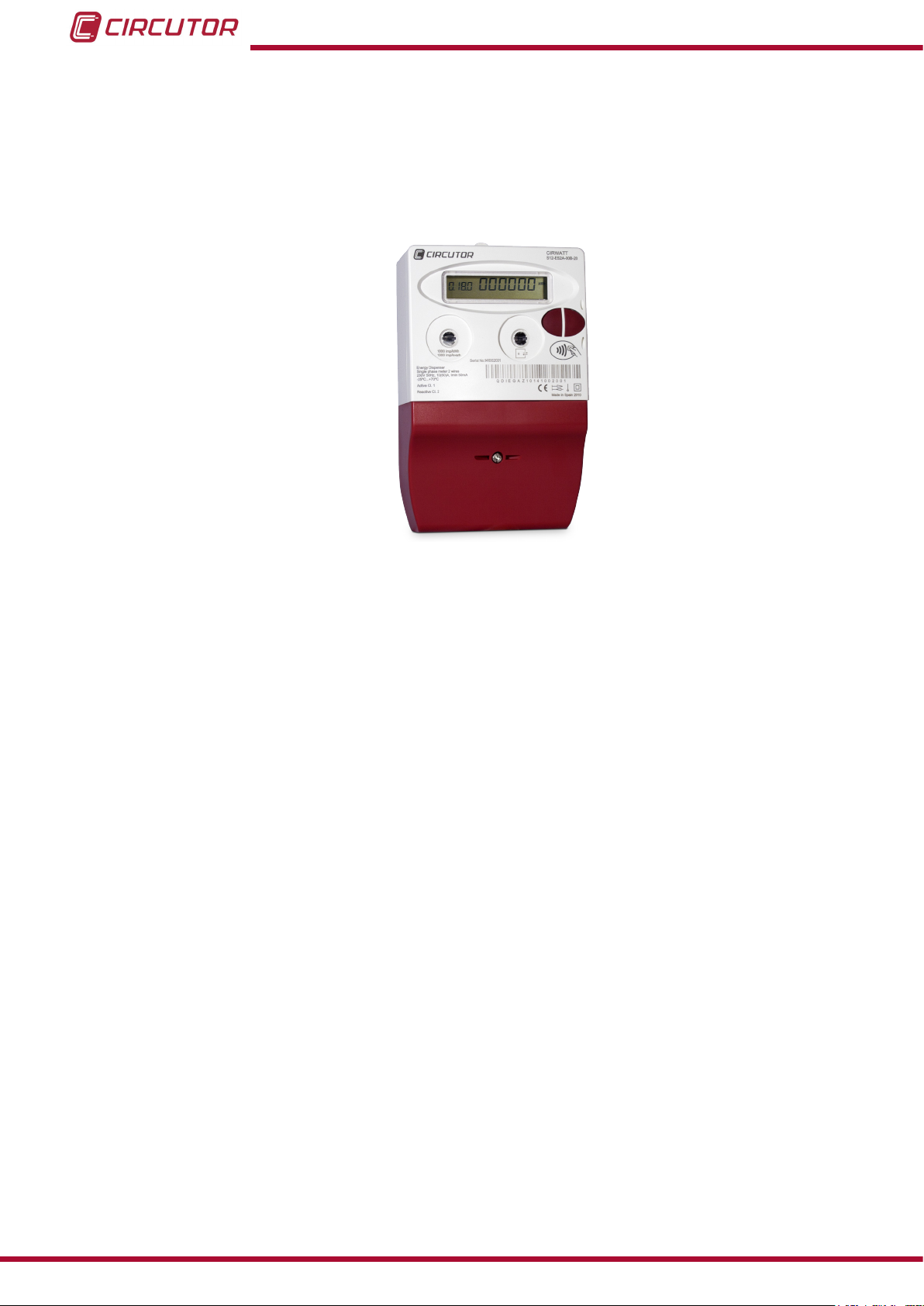
The Dispenser Universal is the unit that is installed in the user's home. It is an energy meter
with the capacity to manage user consumption from a micro-grid according to the status of the
grid.
It is designed according to the EN 62053-21:2003 standard for active energy classes 1 and 2
and according to the UNE-EN 62053-23:2003 standard for measuring class 2 reactive energy.
Figure 1:Image of the Dispenser Universal
The unit features:
- Display , which shows the information of the user's contract.
- Two buttons, used to browse the display screens and recover the power supply in the
event of a power cut.
- 2 indicator LEDs: Verication and Pilot�
- RS-485 communications, with the MODBUS RTU® protocol
- 1 general relay output, which allows the activation/deactivation of the power supply.
- 1 auxiliary relay output, which allows the activation/deactivation of the secondary loads.
- RFID card reader, used to load the contract generated in the DISPENSER-SOFT application.
8
Instruction Manual
Page 9
Dispenser Universal System
3�- BASIC CONCEPTS
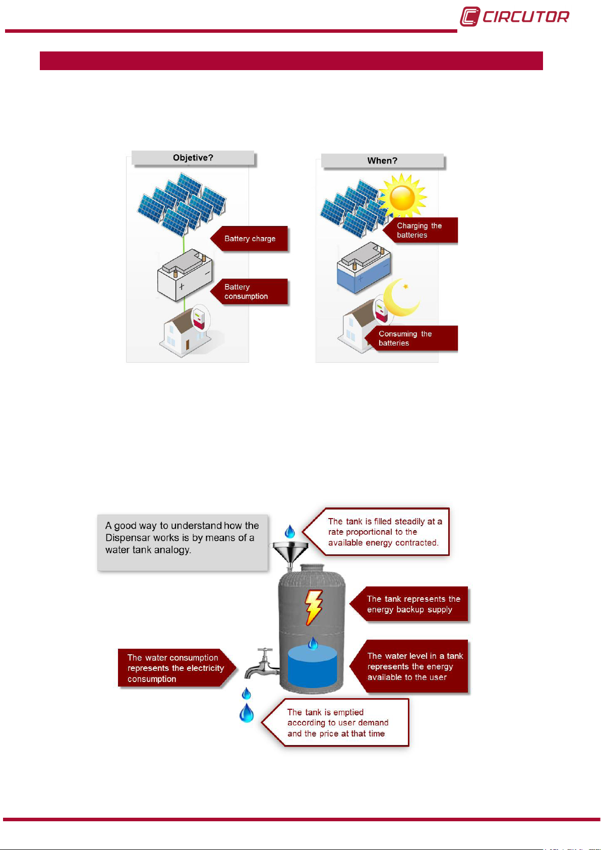
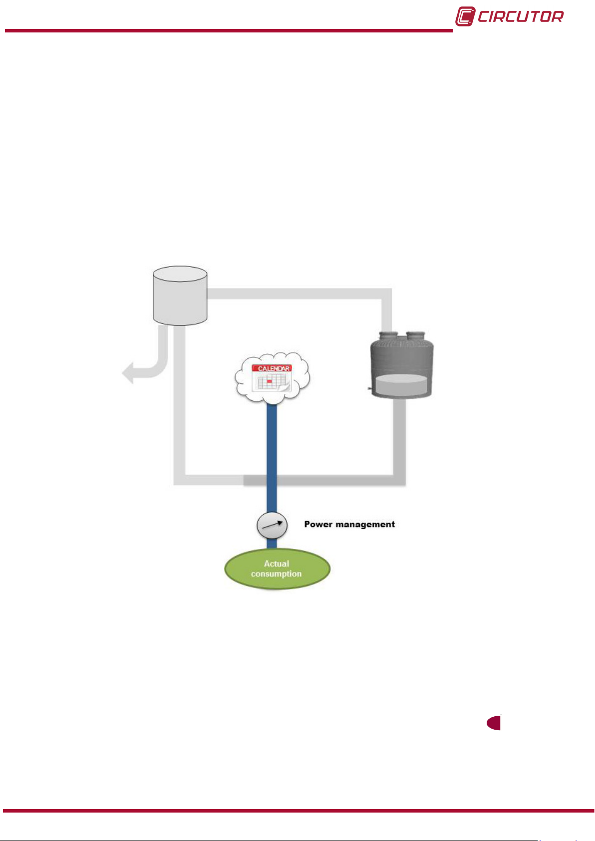
The energy storage systems in a micro-grid can be charged with the use of renewable energies
during the periods of maximum insolation. Stored energy can then be consumed during the rest
of the day.
Figure 2: Purpose of the Dispenser Universal
The main purpose of the Dispenser Universal system is to control the energy demand and
power of the different users of a micro-grid, with the aim of satisfying the energy needs of each
user.
A good way to describe the operation of the Dispenser is with a water tank analogy, Figure 3.
Instruction Manual
Figure 3: Water tank analogy�
9
Page 10
Dispenser Universal System
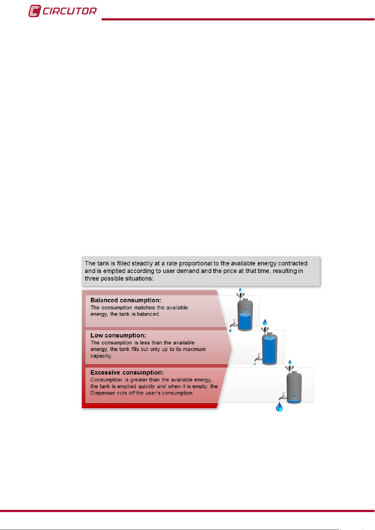
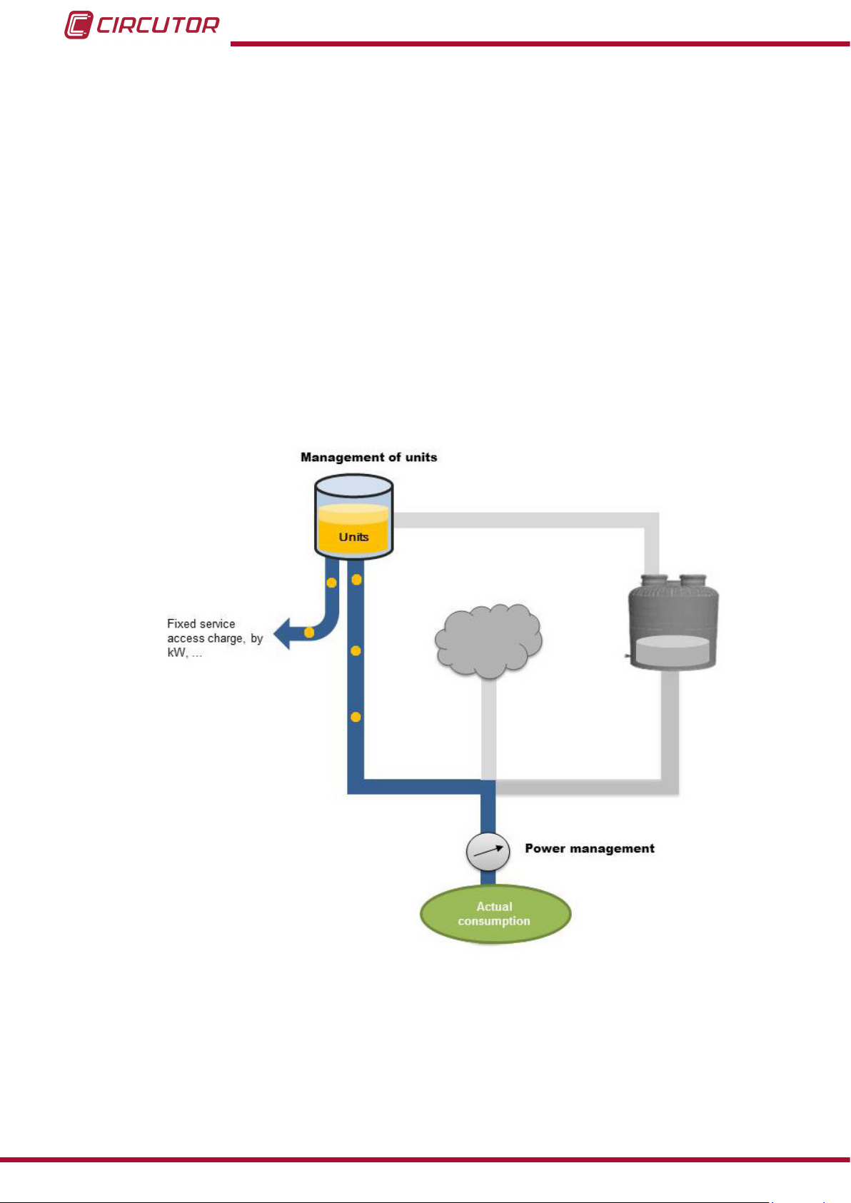
Energy can be stored in the Dispenser so that it is readily available. The capacity of the Dispenser would be equivalent to that of the water tank, i.e., the larger the tank, the higher the
volume of water available.
The tank is lled according to the contracted ow rate. In the case of the Dispenser, the tank
is lled constantly at a rate proportional to the contracted energy. If this ow rate is insufcient,
the contract can be modied and adapted to current needs.
The consumption of water is equivalent to the consumption of energy, i.e., the higher the consumption rate, the quicker the tank will be emptied. In particular, there are three different scenarios:
Balanced consumption, the lling and emptying rate of the tank is very similar, so
there is always an acceptable level of water that can meet the needs of users at all times.
Low consumption; in this scenario the lling rate is higher than the emptying rate, so
the tank is usually lled up to the top. This is not the optimum scenario, since the purpose
of the management system is not to store the maximum amount of water (energy), but to
nd the balance between load and consumption.
Excessive consumption; in this scenario, the lling rate is much slower than the emptying rate, so the tank is fully drained leaving no available water (energy), which leads to
a critical situation.
10
Figure 4: Management of the water tank lling/emptying procedures.
Instruction Manual
Page 11
Dispenser Universal System
3.1.- OPERATING MODES
The Dispenser has three operating modes, depending on the load of the energy storage systems:
Normal mode,
Bonus mode,
Restriction mode,
3�1�1�- NORMAL MODE
This operating mode corresponds to a situation in which there is a balance between the energy
available in the storage systems of the micro-grid and the consumed energy.
Following the water analogy, the normal mode represents the balance between lling and emptying of the water tank.
This is the most benecial situation for a micro-grid and for the user. Therefore, the objective is
to work under these conditions at all times.
3�1�2�- BONUS MODE
In this case, the storage systems have managed to store the maximum amount of energy after
various insolation periods. In turn, the consumption of energy by users is not excessive.
This is when a bonus is applied to the consumption of energy, reducing its price.
3�1�3�- RESTRICTION MODE
In this case, either the storage system has not fully charged after a period of time or there has
been excessive consumption by users. Therefore, the consumption of energy must be limited
by means of increasing its price.
3�1�4�- EXAMPLE
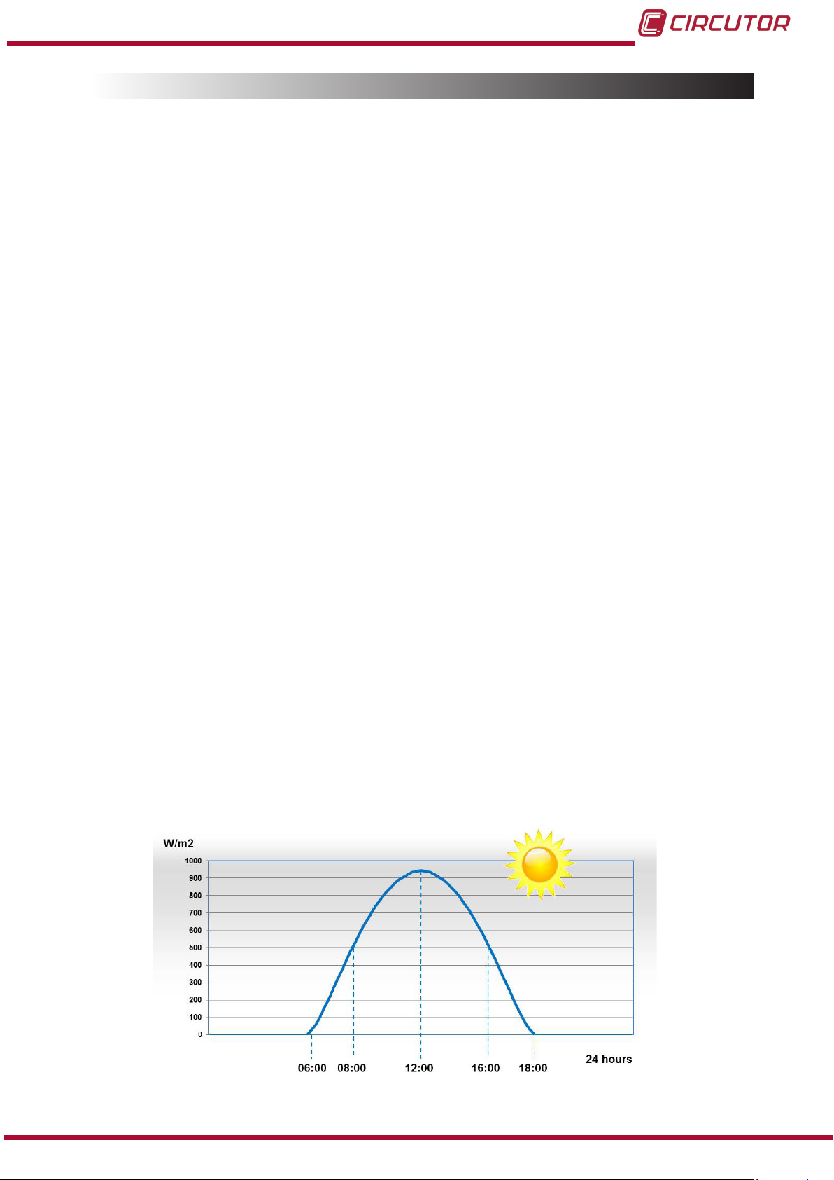
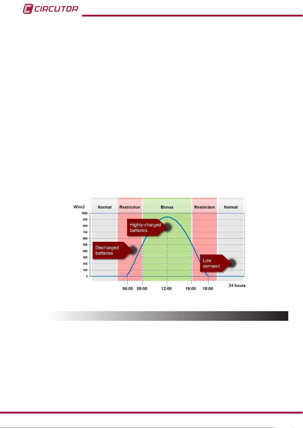
The irradiation curve in Figure 5 shows an insolation period between 06:00h and 18:00h, reaching the maximum level of insolation at 12:00h.
Instruction Manual
Figure 5: Example of an irradiation curve�
11
Page 12
Dispenser Universal System
Different bonus or restriction periods can be dened according to the following criterion:
The energy levels of the energy storage systems are low rst thing in the morning, since
the users of the micro-grid have consumed energy during the night period. Therefore, a period
of time between 05:00h and 08:00h must be dened, in which penalties will be applied to consumption. In this case, the unit will be operating in the restriction mode.
The next period, between 08:00h and 16:00h, is the period of maximum insolation, during
which the photovoltaic energy is enough to charge the storage systems and supply energy to
users, so consumption should be encouraged during this period. In this case, the unit operates
in the bonus mode.
The maximum number of users will connect loads to the grid between 16:00 and 19:00.
Even though the previous period was not of maximum insolation, if a message is not shown
to the users during this period, warning them about the fact that the cost of energy can be
higher than usual, simultaneous loads might be connected to the micro-grid, which will quickly
consume the energy stored in the storage systems. During this period, the unit operates in
restriction mode.
Finally, a period is established for the rst and last 5 hours of the day, during which it is
assumed that the consumption from the grid is not critical. Therefore, a period during which
the unit works in normal mode can be dened.
Figure 6: Example of Operating modes�
12
3.2.- ENERGY FACTORS
The Dispenser can manage the price of energy according to the operating mode of a micro-grid through the Energy factor parameters:
Bonus factor; when the micro-grid is in the bonus mode (excess energy is available),
the price of energy can be reduced and users can consume it at a lower price.
Restriction factor, if, on the other hand, the micro-grid is in the restriction mode (not
much energy is available), the price of energy can rise and users will pay more for the
energy they consume.
Instruction Manual
Page 13
Dispenser Universal System
In normal mode, the price of energy remains unmodied and users pay for energy at the price
stipulated.
Table 2 shows the values that these factors can adopt.
Table 2: Range of values of the energy price factor
Energy factors Range of values
Bonus factor 0.4...1
Restriction factor 1.2...3
3.3.- CONTROLLING THE MAXIMUM POWER
One of the functions of the Dispenser is to control the limits of the power that can be consumed
by the user.
The unit limits the maximum power available according to the type of contract and status of the
micro-grid. If this power level is exceeded, the general relay is opened, disconnecting the power
supply from the subscriber. ( 5.2.4.1.- GENERAL RELAY)
This function allows each user of the installation to dene the maximum power available, establishing the number of loads that can be connected to the grid. Therefore, this limiter can be used
to ensure that the power for which the electrical network has been designed is never exceeded.
The Contracted power is dened in the DISPENSER-SOFT application as:
Contracted power = Base power x Power multiplier�
Where: Base power : base power of the micro-grid.
Power multiplier : multiplier factor that depends on the type of contract.
The maximum power value is modied according to the status of the micro-grid.
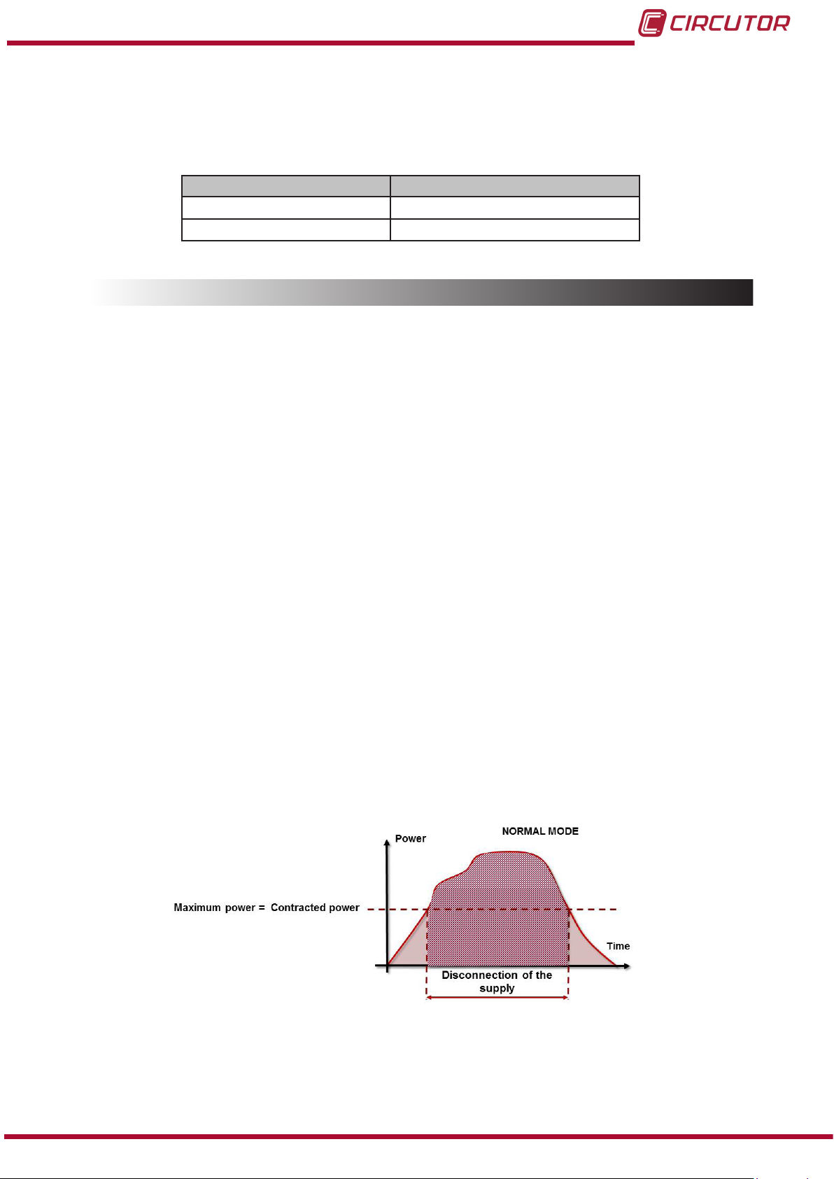
3�3�1�- NORMAL MODE
In this operating mode, the maximum power that can be consumed by the user is equal to the
contracted power.
Instruction Manual
Figure 7: Controlling the maximum power, Normal mode�
13
Page 14
Dispenser Universal System
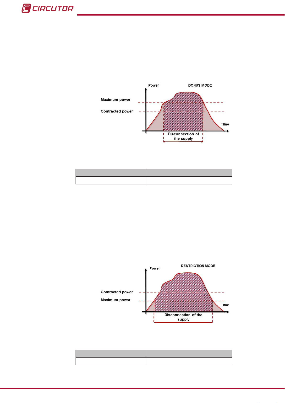
3�3�2�- BONUS MODE
When the micro-grid is operating during an excess power period, the Dispenser allows the
user to consume more power than that established by the user's contracted energy.
To do so, the Excess factor parameter has been dened in the DISPENSER-SOFT application
as a multiplier factor that increases the value of the maximum power available for consumption.
Figure 8: Controlling the maximum power, Bonus mode�
Table 3: Range of values of the excess factor�
Power factor Range of values
Excess factor 1...3
3�3�3�- RESTRICTION MODE
If, on the other hand, the micro-grid is in the power limiting mode, the Dispenser will reduce
the maximum power available for consumption, also reducing the power that the user can consume.
The Limiting factor parameter has been dened in the DISPENSER-SOFT application as a
multiplier factor that reduces the value of the maximum power available for consumption.
14
Figure 9: Controlling the maximum power, Restriction mode�
Table 4: Range of values of the limiting factor�
Power factor Range of values
Limiting factor 0...1
Instruction Manual
Page 15

Dispenser Universal System
3.4.- OPERATING MODES
The Dispenser can work in two operating modes:
Frequency mode�
Schedule mode�
3�4�1�- FREQUENCY MODE
With the frequency mode activated, the power and energy factors and the status of the aux-
iliary relay are programmed according to the frequency of the grid at each moment.
3�4�2�- SCHEDULE MODE
NB: The schedule mode is selected automatically if the frequency mode is not enabled.
The schedule mode is based on the denition of the conditions under which the micro-grid will
operate, according to the time of day.
With DISPENSER-SOFT, the operator can dene up to four conditions and distribute them in
four daily time zones.
The user can dene up to six types of day (working day, holiday, etc.) and four types of season
(rainy season, dry season, etc.) in order to improve energy management efciency.
Instruction Manual
15
Page 16
Dispenser Universal System
3.5.- TARIFF SYSTEM
The unit features a tariff system composed of four different types of contracts.
This system is responsible for fully adapting to the needs of each customer. The user will nd
specic and common parameters associated with each type of contract.
16
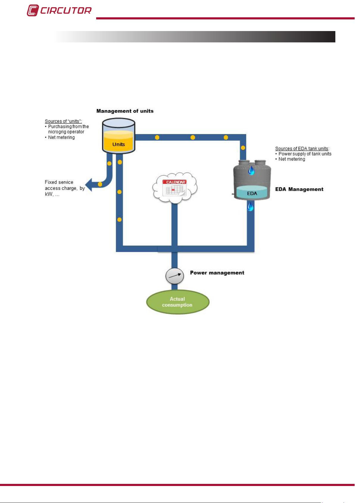
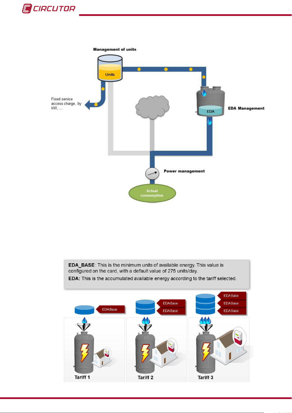
Figure 10:Hydraulic diagram of the tariff system�
The hydraulic diagram shown in Figure 10 provides a general description of how the tariff system of the Dispenser works. Not all tariffs include all the elements of the diagram and the customer must select the tariff that best suits their needs.
There are four types of contracts:
Type 1: Flat rate for power, where the user is only limited by the instantaneous power
they are consuming.
Type 2: Purchase of energy units. The customer prepays for the energy units. When
these are consumed, the power supply is cut off and the customer must purchase additional units.
Type 3: Purchase of EDA units. This contract is similar to the previous type, but the
customer has an additional tank (EDA tank with EDA units), which provides additional
Instruction Manual
Page 17
Dispenser Universal System
management features when purchasing energy.
Type 4: EDA Flat rate. In this type of contract, the customer can consume a daily av-
erage amount of EDA units, which are only limited by the contracted power of the user.
Unlike the type 3 contract, the customer pays for the days of service. When this period
ends, the unit cuts off the power supply
All contracts have a power limit and a validity expiry date, i.e., if they are not activated before
this date, the Dispenser will not recognise the contract and not close the circuit breaker.
3�5�1�- TYPE 1 CONTRACT: FLAT RATE FOR POWER
Figure 11:Hydraulic diagram of Type 1 contracts
In the case of type 1 contracts, the customer freely consumes energy and is only limited by
the contracted power and power factors, which are applied according to the operating mode
of the micro-grid.
When the user exceeds the contracted power, the unit opens the general relay, cutting off the
power supply to the user.
To recover the power supply, the user must switch off some of its loads and press the button
of the unit. The unit will cut off the power supply within a few seconds if these loads are not
switched off and the user presses the button.
Instruction Manual
17
Page 18
Dispenser Universal System
The contracted power can be dynamically modied according to the customer's needs. To do
so, the customer must contact the operator of the DISPENSER-SOFT and update their contract.
The contract has an expiry date expressed in a number of days. After this period of days, the
Dispenser will open the general relay, cutting off the power supply. To recover it, the subscriber
must pay the operator of the DISPENSER-SOFT for additional days of service.
Days of service can be accumulated, i.e., if only 3 days remain before the expiry of the contract
and the Dispenser is updated with a new contract (an additional 10 days), these days will be
added to the remaining number of days in the customer's current contract.
This type of contract can have no denite time limit, Open-ended contract, with no additional
costs included in the price of energy. Designed for buildings that are not charged for the use
of energy, such as cultural centres, churches, etc.
3�5�2�- TYPE 2 CONTRACT: PURCHASE OF ENERGY UNITS
18
Figure 12:Hydraulic diagram of Type 2 contracts
3�5�2�1�- CONCEPTS : ENERGY UNITS AND NET METERING
The energy unit concept has been dened in the Dispenser Universal as the units that the
customer must purchase from the operator of the micro-grid to receive energy.
Instruction Manual
Page 19

Dispenser Universal System
The net metering concept is applied to customers that have their own self-powered generator (usually a solar power generator).
Customers with a self-powered generator can consume the energy that is self-generated instantaneously. However, excess production of energy might not need to be consumed during
some times of day. This is when the surplus energy can be injected into the electrical network
of a micro-grid and the Dispenser will reward the user by adding energy units that can be con-
sumed later.
This surplus energy injected into the grid is subject to the operating mode of the micro-grid at
the time of injection. The unit can measure the injected energy and manage it:
Applying penalties to energy injected during bonus periods.
Awarding a bonus to energy injected during restriction periods.
Example of net metering:
A subscriber installs solar panels at their home to generate their own electricity. At a certain time
of day, the amount of energy generated by these solar panels exceeds the current consumption. In this case, the surplus energy of the panels would be injected into the electrical network
of the micro-grid. The Dispenser will apply a penalty or bonus to the injected energy, according
to the operating mode of the micro-grid.
Micro-grid operating in the normal mode (Price factor =1):
If 1 Wh is injected into the grid, the Dispenser will add 1 unit of credit to the subscriber.
Micro-grid operating in the bonus mode (Price factor <1):
If 1 Wh is injected into the grid, the Dispenser will add <1 unit of credit to the subscriber. If the
price factor is 0.8, 0.8 units will be added to the user and not 1, since the micro-grid is operating
in the bonus mode and needs no additional energy.
Micro-grid operating in the restriction mode (Price factor >1):
If 1 Wh is injected into the grid, the Dispenser will add >1 unit of credit to the subscriber. If the
price factor is 1.5, 1.5 units will be added to the user and not 1, since the micro-grid is operating
in the restriction mode and needs additional energy, applying a bonus for the subscriber for the
injected energy.
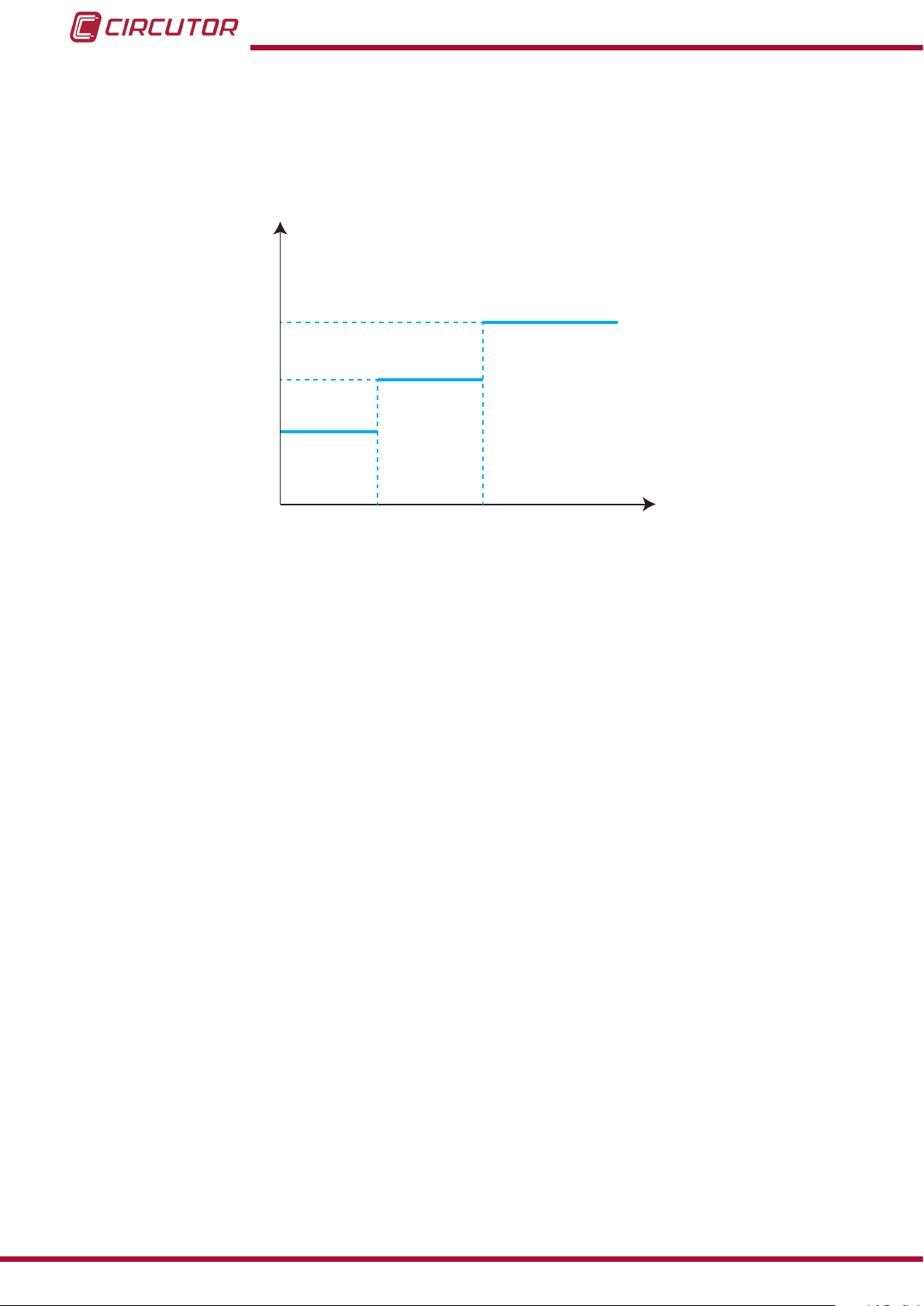
3�5�2�2�- ENERGY BLOCKS CONCEPT
In the energy block operating mode, the price of energy varies according to the consumption.
The user can dene 3 energy blocks through DISPENSER-SOFT, selecting the following for
each block:
- The price of energy of each block ( Price factor).
- The consumption after which the system skips to a different block (Energy).
Instruction Manual
19
Page 20
Dispenser Universal System
The period of operation of the energy blocks must also be selected (daily, weekly or monthly).
When this period ends, the energy meter resets the value of consumed energy to start consuming from Block 1, where energy is cheaper.
Energy price
(€/Wh)
Block 3
Price factor 3
Price factor 2
Block 1
Block 2
Price factor 1
Consumption (kWh)
Energy 1 Energy 2
Figure 13:Energy blocks�
NB: If the Dispenser has no active contract when the energy meter is reset, the meter will not
be reset and the user will continue consuming energy at the price of the current block.
NB: The energy factors, bonus and restriction factors can be available at the same time when
the system is operating in the energy blocks mode.
Example 1: A user in block 2 has an energy price factor of 1�5 (FB). The micro-grid is in the
bonus mode with an energy price factor of 0�8 (FM).
The nal factor applied to the subscriber will be:
20
Energy price factor of the customer = FB * FM = 1.5 * 0.8 = 1�2
If you take into account that 1 Wh = 1 unit, when the customer consumes 1 Wh, the Dispenser
will subtract 1�2 units (1.2 Wh)
Example 2: Now let us assume that the customer is in energy block 3 with an energy price
factor of 2 (FB). The energy levels of the micro-grid are low at this moment and it is operating
in the energy restriction mode, with a price factor of 1�4 (FM).
The nal factor applied to the subscriber will be:
Energy price factor of the customer= FB * FM = 2 * 1.4 = 2�8
Therefore, when the customer consumes 1 Wh, the dispenser will subtract 2�8 units.
Instruction Manual
Page 21
Dispenser Universal System
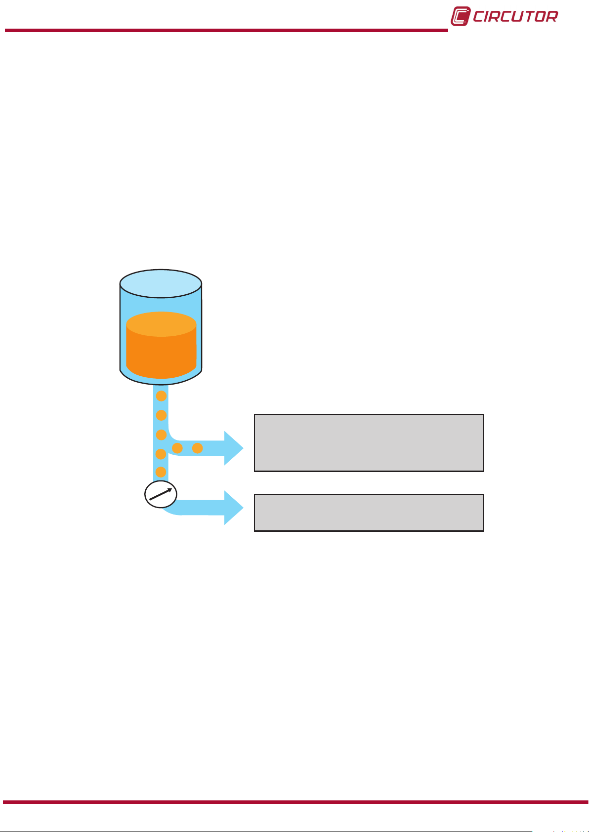
3�5�2�3�- OPERATION
In the case of type 2 contracts, there is a large unit tank that is lled when units are purchased
from the operator or through net metering.
The customer has a credit balance expressed in units, which is consumed in 2 ways (binomial
tariff):
by consumed units.
by xed price, this xed price is subtracted every hour and is recalculated according
to the following equation:
Fixed price = (Price of contracted power x Contracted power )
+ Net metering access charge
+ Other costs
Units
Fixed price
- The units are deducted every hour
- Contracted power ratio and other charges
Meter
Units consumed
In nominal conditions 1Wh = 1unit
Figure 14:Representation of the consumption in the unit tank
Two energy meters are used to control the unit tank:
a unit meter, which measures the units in the tank. These units will decrease as the
subscriber consumes energy and increase when units are purchased from the operator
or through the net metering balance.
Under normal conditions, the 1Wh to 1 unit ratio is 1:1.
an energy block meter, which is used when the price of energy depends on the con-
sumption level of the user during a period of time.
This type of contract can have no denite time limit, Open-ended contract, with no additional
costs included in the price of energy. Designed for buildings that are not charged for the use
of energy, such as cultural centres, churches, etc.
Instruction Manual
21
Page 22
3�5�3�- TYPE 3 CONTRACT: PURCHASE OF EDA UNITS
Dispenser Universal System
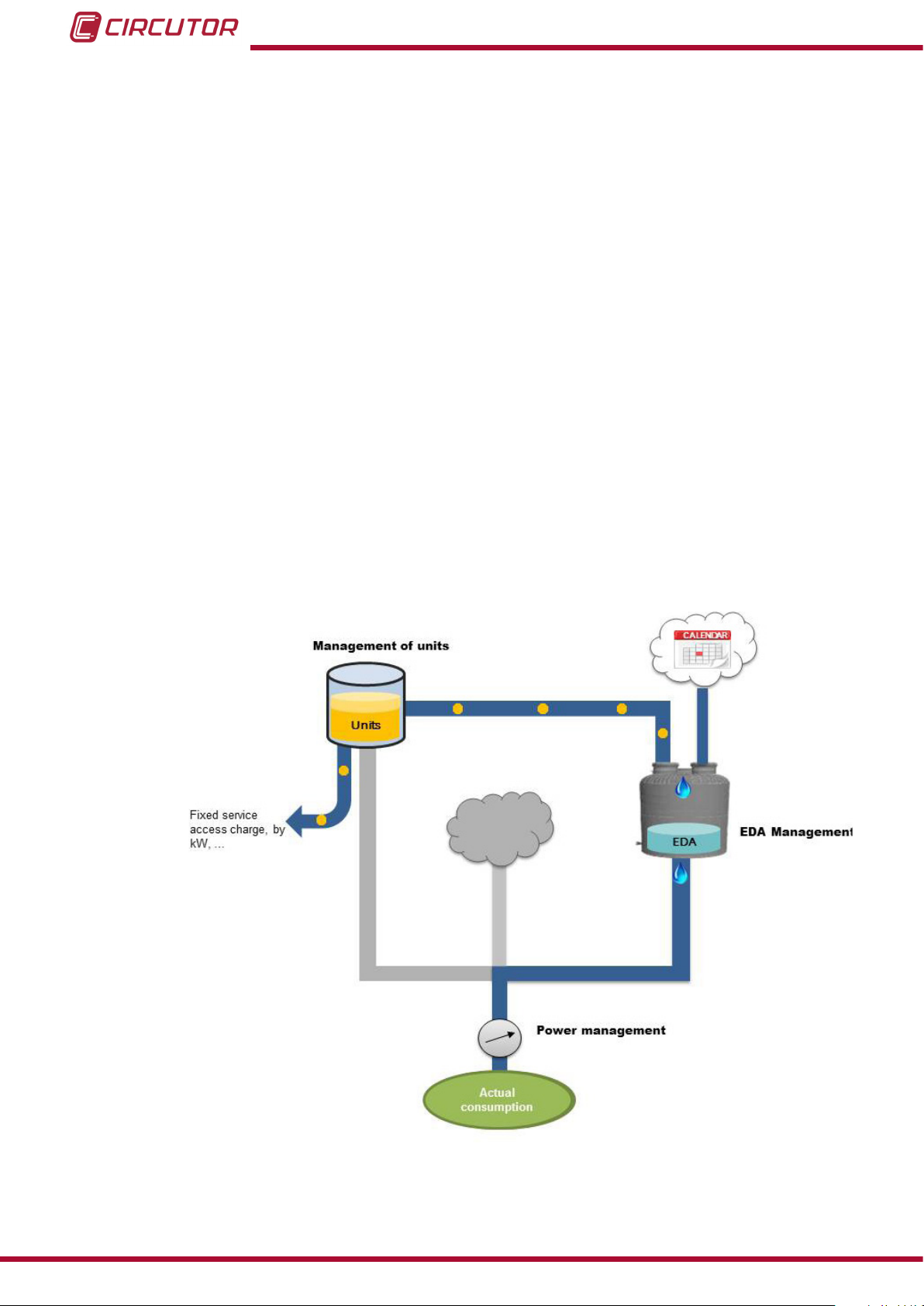
Figure 15:Hydraulic diagram of Type 3 contracts
3�5�3�1�- EDA UNIT CONCEPT
The EDA is dened as the Energy Daily Allowance.
And the base EDA is dened as the minimum energy available during one day.
22
Figure 16: EDA and BASE_EDA
Instruction Manual
Page 23
Dispenser Universal System
The operator must dene the value of the BASE EDA in Dispenser-Soft
The value of the EDA can vary according to the operating mode of the micro-grid with the bonus
and restriction factors.
Continuing with the water tank analogy, the EDA concept corresponds to the lling speed of the
water tank.
The EDA tank can be lled in two ways:
Once a day, at the time established by the customer.
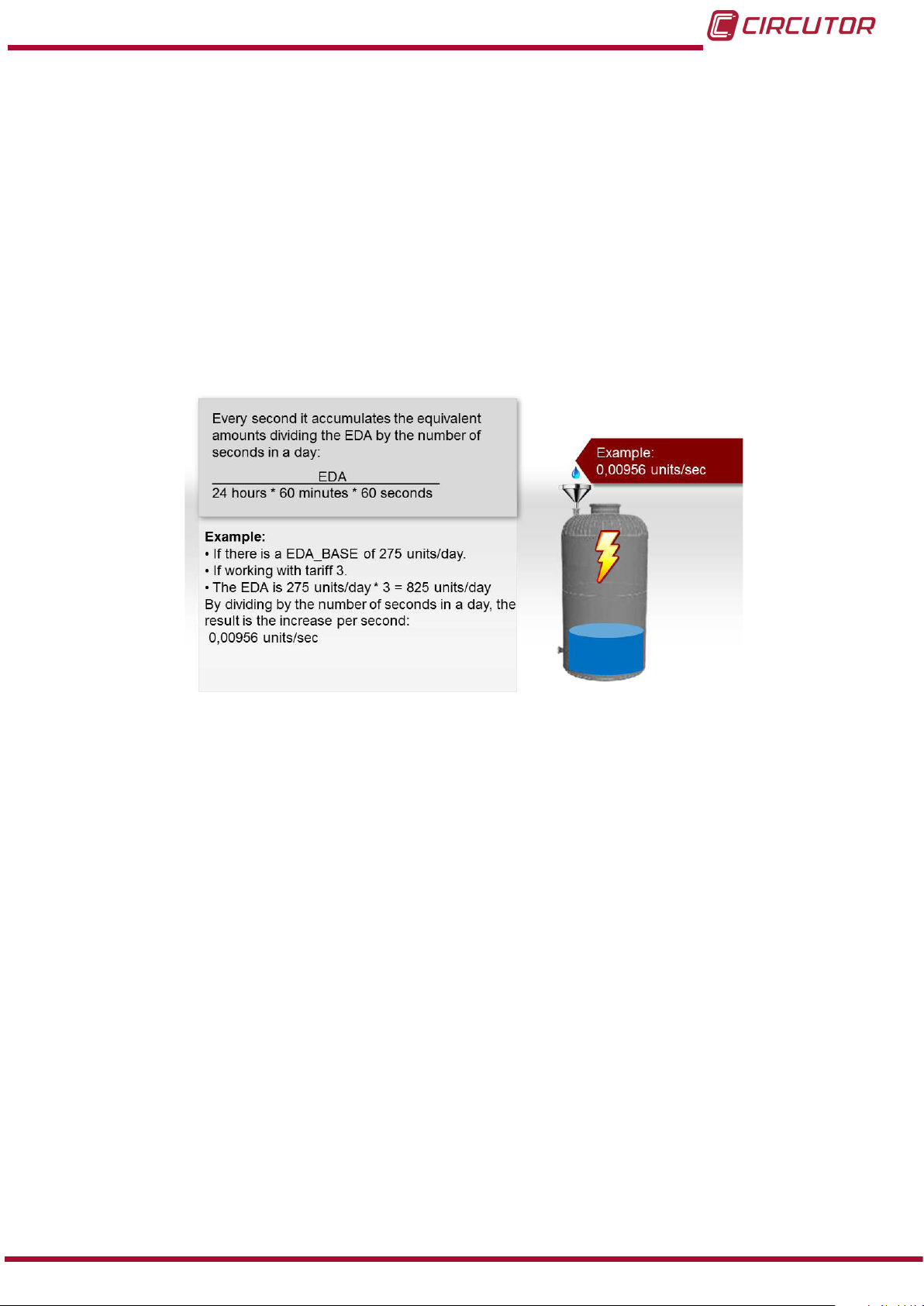
With dripping systems. When this option is selected, the tank lling speed can be
calculated with the formula shown in Figure 17�
Figure 17:Filling speed of the EDA tank
3�5�3�2�- DEFINITION OF THE SIZE OF THE TANK
Users of a micro-grid can have tanks of different sizes.
Therefore, the EDA_CAP is dened as the nominal capacity, i.e., the number of EDA units that
can be stored in a tank.
Nominal CAPACITY = EDA_CAP x EDA
3�5�3�3�- OPERATION
The customer has two types of tanks in this type of contract:
the unit tank.
the EDA tank.
The energy stored in the EDA tank decreases according to consumption and the xed price and
it increases as units are transferred from the unit tank to the EDA tank and according to the net
metering values.
Such a transfer of energy from one tank to another varies according to whether the dripping
Instruction Manual
23
Page 24
Dispenser Universal System
parameter has been activated or not.
When the dripping parameter has been activated, the assigned energy is stored in the EDA
tank constantly (every second) and at a rate proportional to that of the contracted energy.
When the dripping option has been deactivated, Compact Dispenser mode, energy is transferred once a day.
The unit opens the general relay when the balance of EDA units is depleted or when the system
has been tripped due to an overcurrent.
To recover the power supply, the customer must wait until the EDA tank is lled by means of
transferring units from one tank to another or by charging it with EDA units purchased from the
DISPENSER-SOFT operator.
If the EDA balance is used up and the tank is filled after activating the dripping option, the general relay will be automatically rearmed, following a reclosing sequence that varies according
to the times the power supply has been cut off during the day (See 5.2.4.1.- GENERAL RELAY).
This type of contract can have no denite time limit, Open-ended contract, with no additional
costs included in the price of energy. Designed for buildings that are not charged for the use
of energy, such as cultural centres, churches, etc.
3�5�4� - TYPE 4 CONTRACT: EDA FLAT RATE
24
Figure 18:Hydraulic diagram of Type 4 contracts�
Instruction Manual
Page 25

Dispenser Universal System
In the EDA Flat rate mode, the customer can consume an average amount of EDA units which
is pre-dened and limited by the contracted power.
If the energy daily allowance has not been consumed, it can be stored in the EDA tank up to its
nominal capacity, which has been previously programmed in the card.
Unlike type 3 contracts, the customer pays for the days of service and when these end, the
customer must purchase additional days of service from the DISPENSER-SOFT operator.
The supply is cut off after this period.
If the EDA balance is used up and the tank is filled after activating the dripping option, the general relay will be automatically rearmed, following a reclosing sequence that varies according
to the times the power supply has been cut off during the day (See 5.2.4.1.- GENERAL RELAY).
This type of contract can have no denite time limit, Open-ended contract, with no additional
costs included in the price of energy. Designed for buildings that are not charged for the use
of energy, such as cultural centres, churches, etc.
Instruction Manual
25
Page 26
Dispenser Universal System
4�- DISPENSER-SOFT
4.1.- GENERAL DESCRIPTION
DISPENSER-SOFT software allows the managers of a micro-grid to:
Congure the tariff system
Manage the different states of the micro-grid, according to its level of energy.
DISPENSER-SOFT uses the MS SQLServer database, which is free and included in the software installation CD.
DISPENSER-SOFT is supplied with the following:
An Activation licence (USB Dongle), which is required to use the software after it has
been installed.
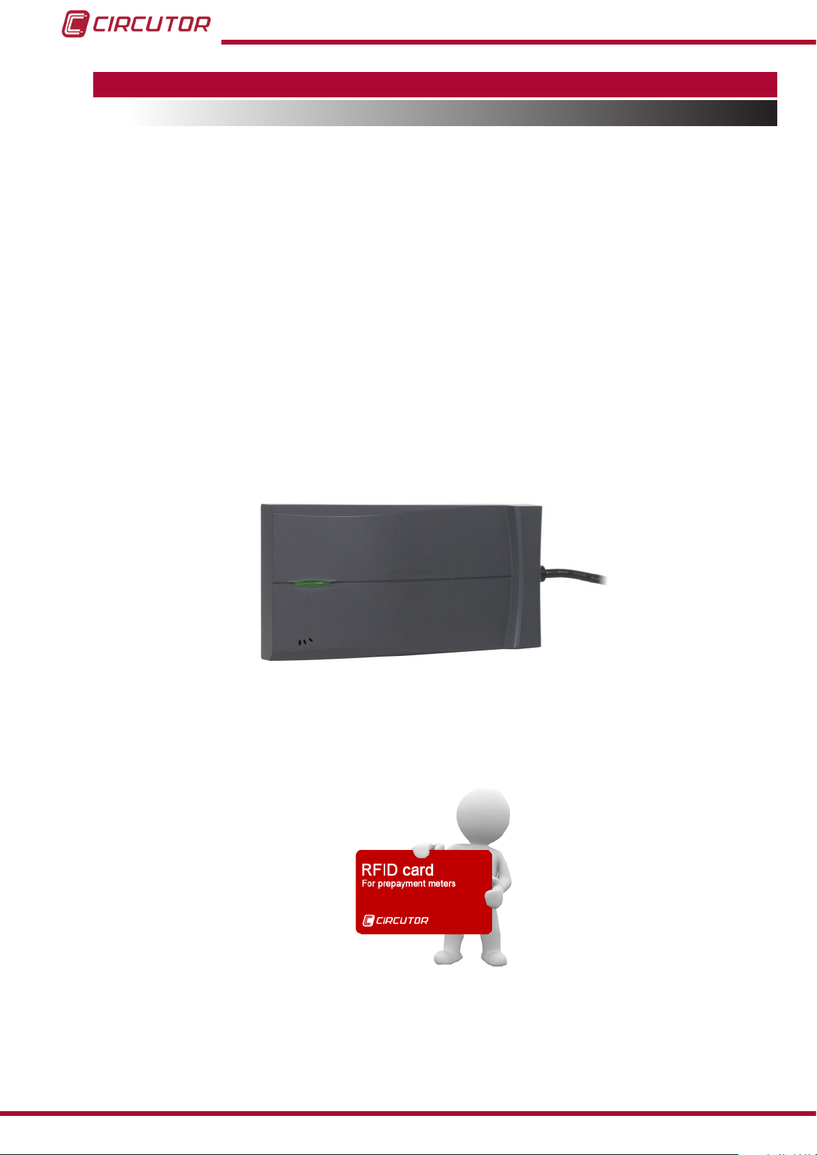
An RFID card reader/writer, which reads, writes, formats and modies user cards.
This unit is connected to the USB port of the computer in which the DISPENSER-SOFT
software is installed.
An RFID card, which is used as the connection element between the DISPENS-
ER-SOFT and Dispenser Universal software. It includes all the information so that it
can be read by Dispenser Universal and establish the operating mode according to the
parameters saved in the card. All cards are personal and non-transferable.
26
Instruction Manual
Page 27
Dispenser Universal System
4.2.- INSTALLATION
DISPENSER-SOFT is only compatible with the 32 and 64-bit Windows 7 and
Windows 8 operating systems.
Insert the Installation CD in the CD drive of the computer from which the micro-grid will be
managed to start the installation process. The installation process will start automatically after
the installation CD has been inserted.
4�2�1�- INSTALLATION OF THE MS SQLService DATABASE
The installation process starts with the installation of the SQL Service database if it is not installed in the computer.
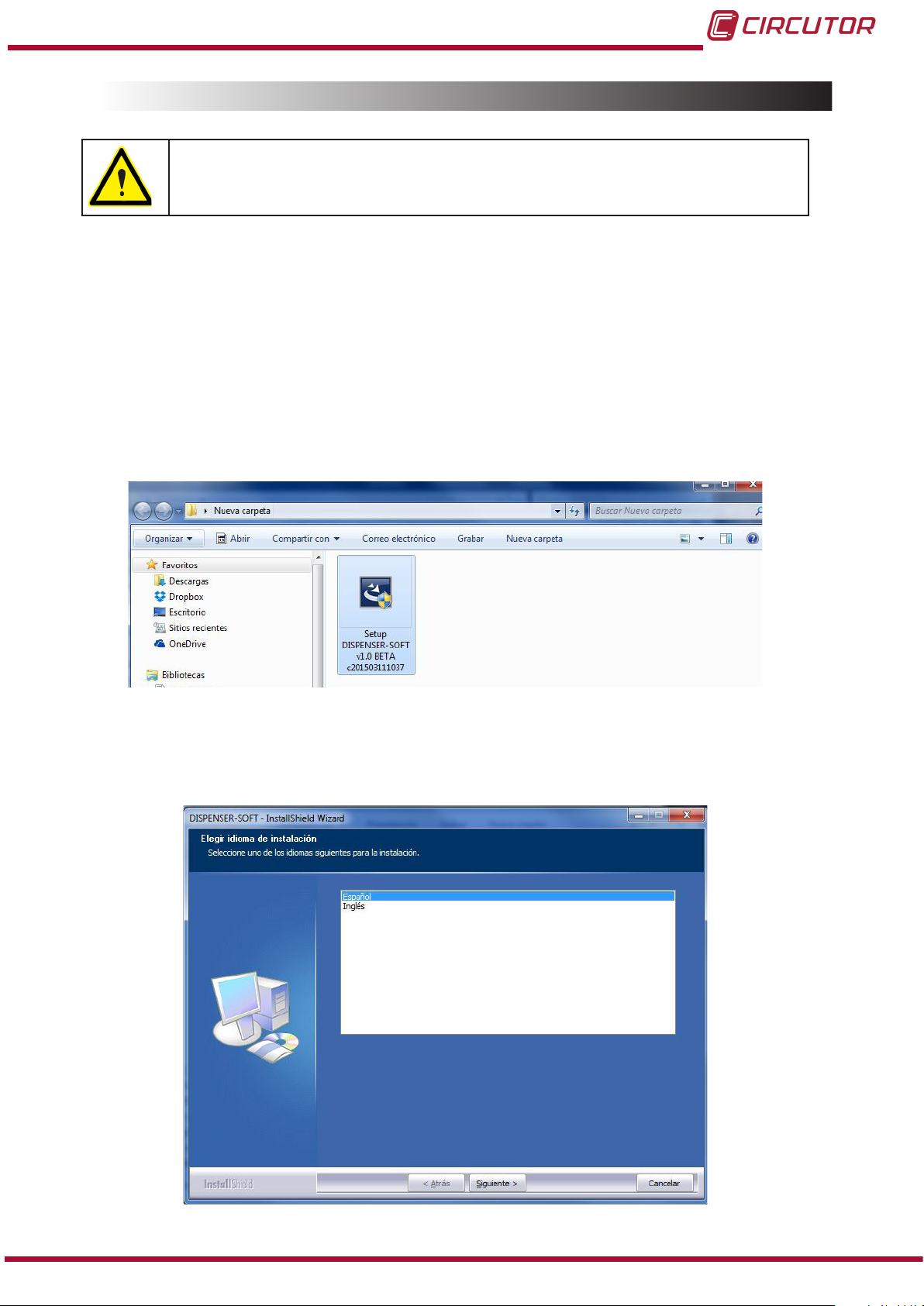
To start the installation, open the DISPENSER-SOFT installation le (Figure 19).
Figure 19: Installation of the MS SQLService database
The SQL database installation process will start after the le has been opened.
Firstly select the installation language (Figure 20).
Instruction Manual
Figure 20: Installation of the MS SQLService database (Step 1)�
27
Page 28
Dispenser Universal System
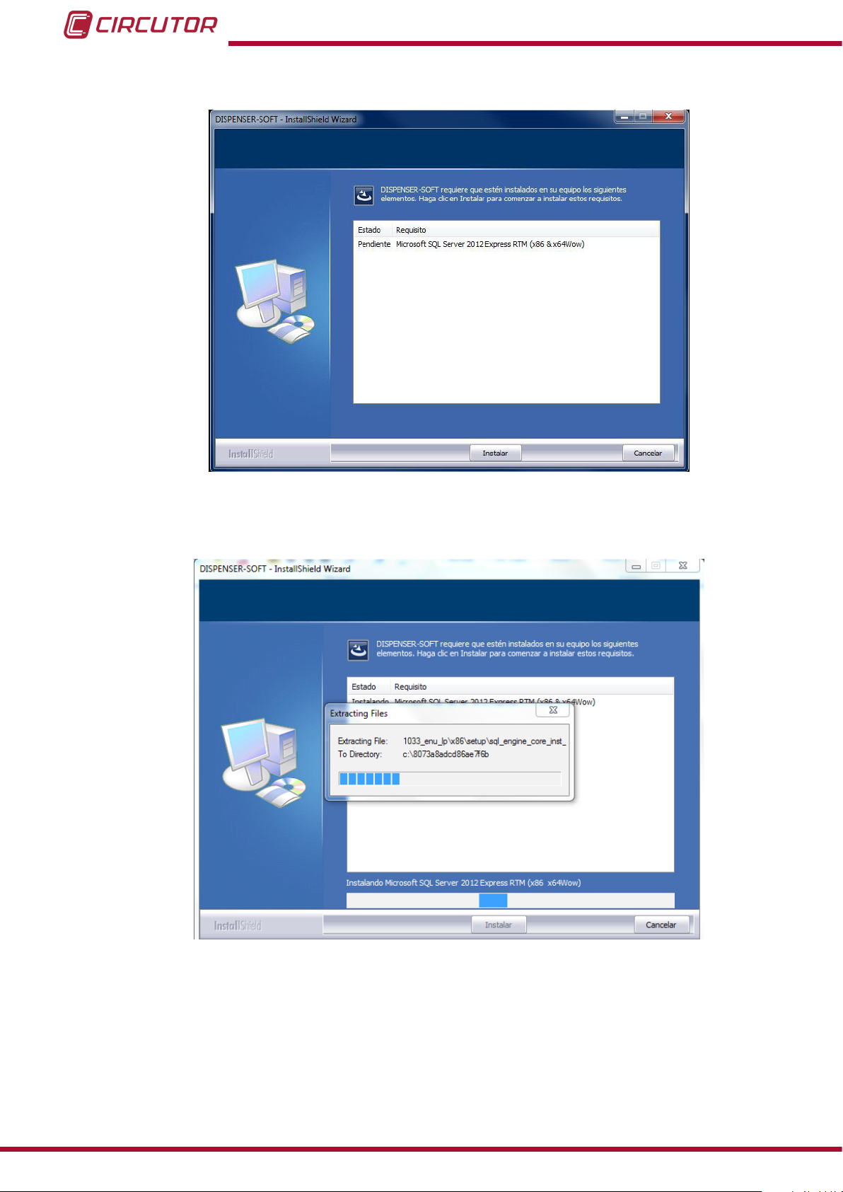
Click on the Next button to start the database installation process (Figure 21).
Figure 21: Installation of the MS SQLService database (Step 2)�
Click on the Install button to start the automatic installation process (Figure 22)
28
Figure 22: Installation of the MS SQLService database (Step 3)�
Instruction Manual
Page 29
Dispenser Universal System
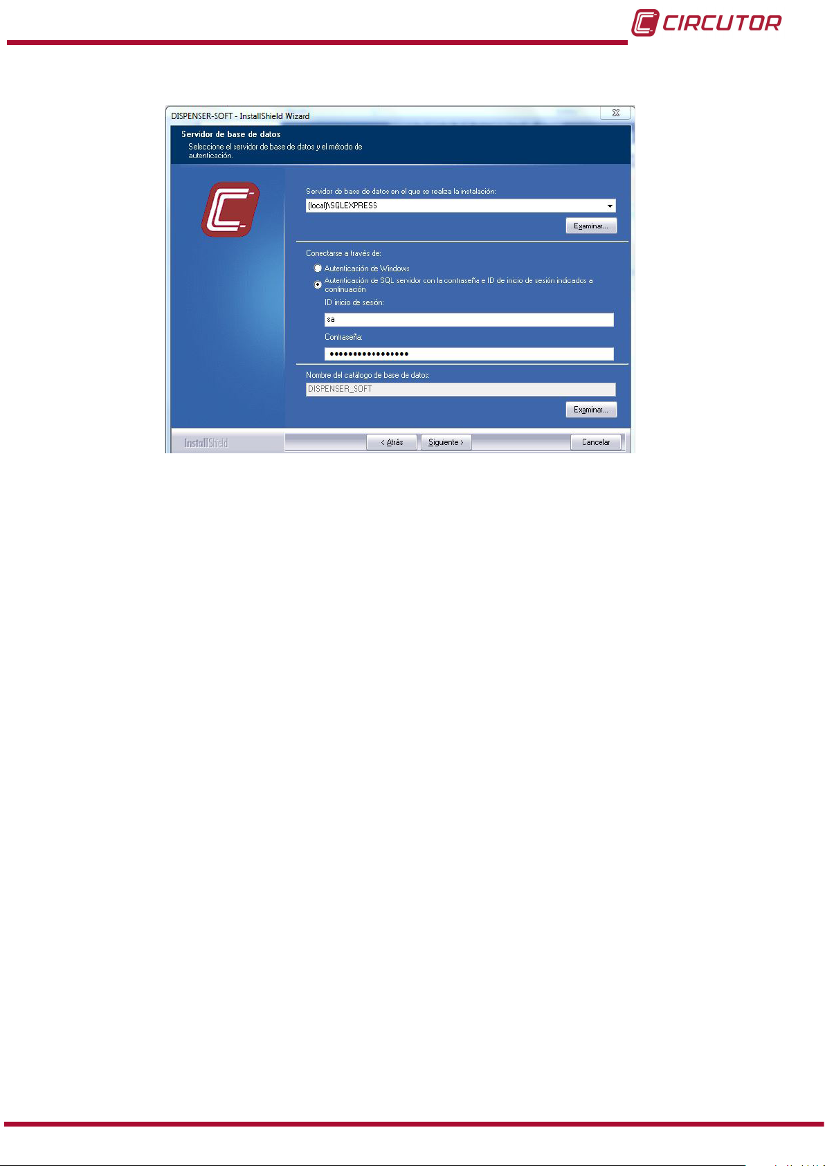
The screen shown in Figure 23 will be displayed after the installation is complete.
Figure 23: Installation of the MS SQLService database (Step 3)�
Select the Authentication of the SQL server with the password and login ID option, enter-
ing the following ID and password:
Login ID: sa
Password: SQLExpress_sa1234
After entering the login ID and password, click on Next to start installing the DISPENSER-SOFT
software.
Instruction Manual
29
Page 30
Dispenser Universal System
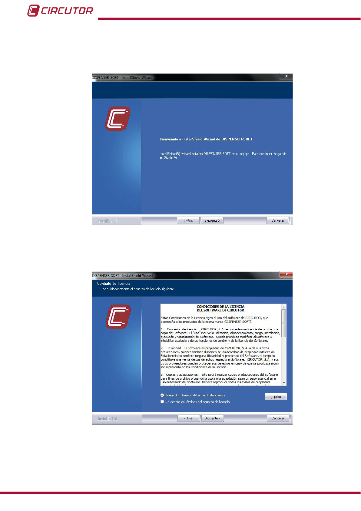
4�2�2�- INSTALLATION OF DISPENSER-SOFT
The DISPENSER-SOFT software will be installed after the database has been installed (Figure
24).
Figure 24: Installation of Dispenser-Soft (Step 1)�
Press the Next button and read and accept the terms and conditions of the licence to use the
DISPENSER-SOFT software, Figure 25.
30
Figure 25: Installation of Dispenser-Soft (Step 2)�
After accepting the terms and conditions of the contract, the user can change the destination
path where the program les and folders will be saved, Figure 26.
Instruction Manual
Page 31

Dispenser Universal System
Figure 26: Installation of Dispenser-Soft (Step 3)�
Click on the Change button to modify the destination directory. The user must select the destination folder of the application, Figure 27.
Figure 27: Installation of Dispenser-Soft (Step 4)�
Select the database server after the path has been established, Figure 28.
Instruction Manual
31
Page 32

Dispenser Universal System
Figure 28: Installation of Dispenser-Soft (Step 5)�
Select the database server that will be used in the Database server from which the software
will be installed section.
This will appear automatically after the installation of the database.
Select the installation server if the computer already has an MS SQLService database installed.
Select one of the following authentication options in the Connect with section:
- Windows authentication, if this option has been selected during the installation of the
database.
- SQL Server authentication with the password and login ID; this option requests the
user to enter the user name and password entered during the installation of the database.
Click on the Next button; the installation process will start,Figure 29.
32
Instruction Manual
Page 33

Dispenser Universal System
Figure 29: Installation of Dispenser-Soft (Step 6)�
When the process is complete, click on the Finish button to complete the installation of the
application, Figure 30.
Instruction Manual
Figure 30: Installation of Dispenser-Soft (Step 7)�
33
Page 34

Dispenser Universal System
4�2�3�- INSTALLATION OF THE LICENCE
To start using the DISPENSER-SOFT software, run the “DISPENSER-SOFT” application
through the shortcut created on the desktop.
If the software is run without the licence (USB Dongle), the following screen will be displayed,
Figure 31.
Figure 31: Installation of the licence (Step 1)�
Insert the USB dongle with the licence into a USB port of the computer and click on Refresh.
The screen shown in Figure 32 will disappear when the user clicks on Continue or after a few
seconds. The software will be ready for use.
34
Figure 32: Installation of the licence (Step 2)�
Instruction Manual
Page 35

Dispenser Universal System
4�2�4�- INSTALLATION OF THE RFID CARD READER/WRITER
Insert the RFID card reader/writer into a port of the computer.
NB A Windows warning message will appear, indicating that the device controller software cannot be installed.
Figure 33: Installation of the RFID card reader/writer (Step 1)�
Insert the CD supplied with the RFID card reader/writer into the PC CD drive.
Open the PC Device Administrator option in the Other devices section, right-click on the
Unknown device option and select the Update controller software��� option, as shown in
Figure 34�
Figure 34: Installation of the RFID card reader/writer (Step 2)�
The window shown in Figure 35 will be displayed; select the Search for controller software
in the unit option.
Instruction Manual
35
Page 36

Dispenser Universal System
Figure 35: Installation of the RFID card reader/writer (Step 3)�
Next, select the device driver by clicking on the Examine button and select the Drivers folder
in the DISPENSER-SOFT folder of the application installed in the PC. (Figure 36)
36
Instruction Manual
Page 37

Dispenser Universal System
Figure 36: Installation of the RFID card reader/writer (Step 4)�
Click on Next after selecting the path where the drivers will be saved.
A Windows warning message will appear for security reasons, asking the user to install the
software of the device. Click on Install (Figure 37).
Figure 37: Installation of the RFID card reader/writer (Step 5)�
The screen shown in Figure 38 will be displayed after the installation is complete.
The device will be ready for use.
Instruction Manual
37
Page 38

Dispenser Universal System
Figure 38: Installation of the RFID card reader/writer (Step 6)�
4.3.- OPERATION
When the DISPENSER-SOFT software is run for the rst time, the screen shown in Figure 39
will be displayed� Click on Yes to open the software.
38
Figure 39: User account control screen�
Enter a user name and password to access the main screen of DISPENSER-SOFT (Figure 40).
Instruction Manual
Page 39

Dispenser Universal System
Figure 40: User Screen�
The default user name and password are:
Table 5:Default user name and password�
Default user name and password
User admin
Password admin
The admin user name corresponds to the administrator of the program (Highest user level).
The user name and password should be changed (4.3.6.3.- PASSWORD).
The application has 4 types of users (Basic, Intermediate, Advanced and Administrator), according to the level of access. See “4.3.6.1.- CREATE A USER”
Click on Accept to access the main screen of the application.
4�3�1�- MAIN SCREEN
Figure 41 shows the main screen of the DISPENSER-SOFT software, from which different
menus of the application can be accessed.
Instruction Manual
39
Page 40

Dispenser Universal System
Figure 41: Main screen
The screen is divided into two areas (Figure 42):
Area used to access the different menus of the application.
Central area.
Area to access
the menus
Central area
40
Figure 42: Areas on the main screen�
Instruction Manual
Page 41

Dispenser Universal System
4�3�2�- MICRO-GRIDS MENU
The user can view, create and manage all parameters associated with the micro-grids from this
menu.
Figure 43: Main screen of the Micro-grids menu�
The centre of the screen will display all existing micro-grids. The following options will appear
on the top section of the screen:
Export, if you select an existing micro-grid and click on the Export button, a
.csv le will be created (Excel format), with all data of the micro-grid.
New, to create a new micro-grid. (See 4.3.2.1.- CREATE A MICRO-GRID)
Modify, the parameters of an existing micro-grid can be modied by selecting
a micro-grid and clicking on the Modify button.
Copy, to copy the parameters of a micro-grid.
Delete, to delete an existing micro-grid.
4�3�2�1�- CREATE A MICRO-GRID
NB: Only the administrator and advanced users can create micro-grids.
The screen used to create a new micro-grid will be displayed when you click on the New button,
Figure 44.
Up to 100 micro-grids can be generated
Instruction Manual
41
Page 42

Dispenser Universal System
Figure 44: Screen used to create a new micro-grid�
Fill in the following elds to create a new micro-grid, Table 6:
Table 6:New micro-grid: Micro-grid information�
Parameter Description
Name Name of the micro-grid
Micro-grid identier
Operator
(1)
Select the ID no. of the micro-grid
(Drop-down list, from 1 to 100)
Name of the operator
Phone Contact number of the operator
Geographical coordinates:
Latitude and Longitude
(1)
These elds are not mandatory.
(1)
Latitude and longitude of the micro-grid
If you want the micro-grid to operate in the Frequency mode, enter the frequency values for
each state of the micro-grid, Table 7.
Table 7: New micro-grid: Frequency mode�
Parameter Description Default value
Select the type of generators used in the mi-
Type of micro-grid
cro-grid: Solar power with batteries, Diesel
Solar power with batteries
generator or Other.
Frequency Working frequency of the micro-grid 50 Hz
Hysteresis between
mode changes
Time between the change of states, in seconds 300 s.
Excess Input frequency of the excess factor 52.5 Hz
Limitation Input frequency of the limiting factor. 48.5 Hz
Bonus Input frequency of the bonus factor 52 Hz
Restriction Input frequency of the restriction factor 49 Hz
Auxiliary relay activation
(2)
Default values for a solar power micro-grid with 50Hz batteries.
Frequency required to activate the auxiliary relay. 52 Hz
(2)
42
Instruction Manual
Page 43

Dispenser Universal System
A tariff specied for the micro-grid being created can be generated, modied or added to the
Micro-grid tariffs section.
4�3�2�1�1�- Create a new tariff
To create a new specic tariff for the micro-grid being created, click on the New button in the
New micro-grid screen, Figure 45�
Figure 45: Screen used to create a new micro-grid (Micro-grid tariffs)
The application opens a new screen, where the user can enter all tariff parameters and conditions, Figure 46.
Figure 46:Create a new tariff (General)
This screen shows 6 windows where the following must be lled in:
Instruction Manual
43
Page 44

Dispenser Universal System
1�- General
In this window, Figure 46, enter the following parameters,Table 8.
Table 8:Create a new tariff (General)
Parameter Description
Tariff name Name of the tariff
Tariff description
Contract types
(3)
These elds are not mandatory.
(3)
Description of the tariff
Drop-down list where the type of contract can be selected:
Flat rate, Contract 1: Flat rate for power
Purchase of units, Contract 2: Purchase of energy units
Purchase of EDA units, Contract 3: Purchase of EDA units
EDA Flat rate, Contract 4: EDA Flat rate
2�- Tariff Costs
The tariff costs and period of time during which they are linked are entered in this window,
Figure 47.
44
Figure 47:Create a new tariff (Tariff Costs)
The costs of the tariff depend on the type of contract that has been selected.
Table 9:Create a new tariff (Tariff Costs)
Parameter Description
Price of energy unit
Price of contracted power
Net balance fee
Cost of the energy unit in €/kWh
Only for Type 2,3 and 4 contracts.
Cost of contracted power in €/kW per Day, Week or Month.
(The period of time can be selected)
An access charge can be applied to customers that have their own
self-powered generators. € per Day, Week or Month.
(The period of time can be selected)
Instruction Manual
Page 45

Dispenser Universal System
Table 9 (Cont�) : Create a new tariff (Tariff Costs)
Parameter Description
Other costs
Other costs of a micro-grid € per Day, Week or Month.
(The period of time can be selected)
The price of Contracted power, the Net balance fee and Other costs are added and they
become the Fixed price, which is subtracted from the units to the time.
Fixed price = (Price of Contracted power x Contracted power )+ Net balance fee
+ Other costs
Example: The costs associated with the tariff are:
Price of energy: 0.5€/kWh
Price of contracted power: 0.01€/kW per day
Net balance fee: 1€ per day
Other costs: 2€ per week
Contracted power: 1kW
Fixed price = (0.01 €/kW/day x 1kW ) + 1€ / day + 2€ / week
= 0.01 /24 €/h + 1/24 €/h + 2/ (24x7) €/h
= 0.05 €/h.
Considering that 1 Wh corresponds to 1 unit, in this example 1 unit = 0.0005 €
Fixed price= 0.05 €/h / 0.0005 €/unit = 100 units/h
3�- Tariff conditions
The base parameters are entered and the factors and conditions are dened in this screen,
Figure 48.
Instruction Manual
Figure 48:Create a new tariff (Tariff conditions)
45
Page 46

Dispenser Universal System
The base parameters and the denition of the factors depend on the type of contract:
Type 1 Contract:
Figure 49:Create a new tariff (Tariff conditions - Type 1 Contract)
Table 10:Create a new tariff (Tariff Conditions: Base Parameters)
Base Parameters
Parameter Description Range of values
Power base
Power multiplier
(4)
The Contracted power = Base power x Power multiplier
(4)
(4)
Base power of the customer 100 ... 1000 W
Multiplier of the base power 1 ...100
The contracted power is a xed value, but it can vary according to the Excess and limiting
factors (See 3.3.- CONTROLLING THE MAXIMUM POWER)
Table 11:Create a new tariff (Tariff Conditions: Denition of factors)
Denition of factors
Parameter Description Range of values
Coefcients of contrated power
Excess
Limitation
Factor that increases the maximum power of the installation when the micro-grid is in the bonus mode.
Factor that decreases the maximum power of the
installation when the micro-grid is in the restriction
mode
1 ...3
0 ... 1
46
Instruction Manual
Page 47

Dispenser Universal System
Type 2 Contract:
Figure 50:Create a new tariff (Tariff conditions - Type 2 Contract)
Table 12:Create a new tariff (Tariff Conditions: Base Parameters)
Base Parameters
Parameter Description Range of values
Power base
Power multiplier
(5)
The Contracted power = Base power x Power multiplier
(5)
(5)
Base power of the customer 100 ... 1000 W
Multiplier of the base power 1 ...100
The price of energy and contracted power are xed values that can vary according to the different factors applied:
Excess and limiting factor of contracted power (See 3.3.- CONTROLLING THE MAX-
IMUM POWER)
Bonus and restriction factors applied to the price of energy. (See 3.2.- ENERGY FAC-
TORS)
Table 13:Create a new tariff (Tariff Conditions: Denition of factors)
Denition of factors
Parameter Description Range of values
Coefcients of contrated power
Excess
Limitation
Coefcients of energy price
Bonus
Restriction
Factor that increases the maximum power of the installation when the micro-grid is in the bonus mode.
Factor that decreases the maximum power of the
installation when the micro-grid is in the restriction
mode
Factor to reduce the price of energy when the micro-grid is in the bonus mode
Factor to increase the price of energy when the micro-grid is in the bonus mode
1 ...3
0 ... 1
0.4 ... 1
1.2 ... 3
Instruction Manual
47
Page 48

Type 3 and Type 4 Contracts:
Figure 51:Create a new tariff (Tariff conditions - Type 3 and Type 4 Contracts)
Table 14:Create a new tariff (Tariff Conditions: Base Parameters)
Base Parameters
Parameter Description Range of values
Power Base
Power multiplier
EDA Base
EDA Multiplier
(6)
The Contracted power = Power Base x Power multiplier
(7)
Parameters only for Type 3 and Type 4 contracts.
EDA = EDA Base x EDA Multiplier
(6)
(6)
(7)
(7)
Base power of the customer 100 ... 1000 W
Multiplier of the base power 1 ...100
Contracted base EDA 275 ... 1000 Wh
Base EDA multiplier 1...100
Dispenser Universal System
The price of energy and contracted power are xed values that can vary according to the different factors applied:
Excess and limiting factor of contracted power (See 3.3.- CONTROLLING THE MAX-
IMUM POWER)
Bonus and restriction factors applied to the price of energy. (See 3.2.- ENERGY
FACTORS )
Table 15:Create a new tariff (Tariff Conditions: Denition of factors)
Denition of factors
Parameter Description Range of values
Coefcients of contracted power
Excess
Limitation
Coefcients of energy price
Bonus
Restriction
Factor that increases the maximum power of the installation when the micro-grid is in the bonus mode.
Factor that decreases the maximum power of the
installation when the micro-grid is in the restriction
mode
Factor to reduce the price of energy when the micro-grid is in the bonus mode
Factor to increase the price of energy when the micro-grid is in the bonus mode
1 ...3
0... 1
0.4 ... 1
1.2 ... 3
48
Instruction Manual
Page 49

Dispenser Universal System
Up to 4 different conditions in which the micro-grid will operate can be created, in particular,
these conditions can vary the following:
The Consumption price factor,
The Power factor
The status of the auxiliary relay.
Table 16:Create a new tariff (Tariff Conditions: Denition of conditions)
Denition of conditions
Parameter Description Range of values
Consumption price factors
Condition 1, 2, 3, 4
Power factors
Condition 1, 2, 3, 4
Status of the auxiliary relay
Condition 1, 2, 3, 4
(8)
The Power Cut option immediately opens the general relay.
Select the factor to be applied to the consumption price
Select the factor to be applied to the power
factors
Select the status of the auxiliary relay when
the condition is met
Restriction, Bonus,
Normal
Limitation, Excess,
Normal, Power Cut
Open, Closed
(8)
4�- Schedule mode
In the Schedule mode window, Figure 52, up to 6 types of days can be dened.
Figure 52:Create a new tariff (Schedule mode)
Click on the Modify button to modify a day.
Instruction Manual
49
Page 50

Dispenser Universal System
Figure 53:Create a new tariff (Schedule mode, Denition of the type of day)
A new window will open, Figure 53, where the user can:
Dene the name of the type of day being designed, Description.
Select the start time of the condition for each condition dened in section “3.- Tariff
conditions”.
Note: The start time of Condition 1 must always be 00:00.
Example: Using the example shown in Figure 53, Condition 1 will take effect at 00:00 of a
working day, Condition 2 will take effect at 10:00, Condition 3 at 12:00 and, nally, Condition 4
at 17:00, which will be active until 00:00 of the following day.
A Calendar will be created after the types of days have been created so that the Dispenser
knows what type of day it is (Working day, Holiday, etc.).
The calendar can be divided into four seasons and the months of each season can be selected.
Once the season has been created, the types of days created previously are assigned to each
week.
5�- Energy blocks (See 3.5.2.2.- ENERGY BLOCK CONCEPT)
50
To operate with Energy blocks (only in type 2 contracts), congure the values of the price of
energy of each block and the amount of energy after which the system will change from one
block to another in the window shown in Figure 54 .
The period of time during which the block meter will reset the energy reading to start with Block
1 again can also be congured.
Instruction Manual
Page 51

Dispenser Universal System
Parameter Description Range of values
Figure 54:Create a new tariff (Energy blocks)
Table 17:Create a new tariff (Energy blocks)
Denition of conditions
Default
values
Energy block operating period. When the period is
Period
Block 1, 2 and 3
Price factor Energy price factor
Block 1 and 2
Energy
about to end, the energy meter resets the value of
consumed energy to start consuming from Block
1.
Consumption of energy after which the system
skips to a different block.
Day, Week, Month Day
Block 1 and 2 :
0���5
Block 3: 0���65
0���65 kWh 0
0
6�- Advanced
The end of the contract validity period is congured in the Advanced window, Figure 55.
Instruction Manual
Figure 55:Create a new tariff (Advanced Mode)
51
Page 52

Dispenser Universal System
Table 18:Create a new tariff (Advanced)
Parameter Description
Contracted day price
Accumulation days
Days until end of validity
Price established per contracted day.
Only for Type 4 contracts.
Number of days during which the EDA can be
stored.
Only for Type 3 and 4 contracts.
Period of days allowed to activate the contract. If
the contract is not activated before this date, the
Dispenser will not accept it.
Range of
values
0 ��� 99�99 € 0
0���5 1
1���11000 365
Default
values
4�3�3�- TARIFFS MENU
Additional tariffs can be created and added to any micro-grid existing in the application from this
menu, Figure 56.
52
Figure 56:Tariffs menu
The centre of the screen will display the basic information of existing tariffs. The following options will appear on the top section of the screen:
New, to create a new tariff. The tariff creation process is the same as that
explained in section “4.3.2.1.1.- Create a new tariff”
When tariffs are created from this menu, they are not associated with a micro-grid. To
associate the tariffs with existing micro-grids, open the Micro-grids menu, select the desired micro-grid and click on the modify button and click on Add in the tariffs section. A
window will be displayed with a drop-down list of the tariffs that can be added.
Instruction Manual
Page 53

Dispenser Universal System
Modify, the parameters of the tariff can be modied by selecting an existing
tariff and clicking on the Modify button.
Copy, the copy option speeds up the creation of similar tariffs that only change
in a few parameters.
Delete, to delete an existing tariff.
4�3�4�- DISPENSERS MENU
All Dispensers of a user can be congured in this menu, Figure 56.
Figure 57:Dispensers Menu�
The centre of the screen will display the name, serial number, micro-grid and a brief description
of each Dispenser. The following options will be displayed on the top section:
New, to create a new Dispenser. (See 4.3.4.1.- CREATE A DISPENSER)
Modify, the parameters of the Dispenser can be modied by selecting an
existing Dispenser and clicking on the Modify button
Delete, to delete an existing Dispenser.
Instruction Manual
53
Page 54

Dispenser Universal System
4�3�4�1�- CREATE A DISPENSER
Click on the New button to display the screen used to create a new Dispenser, Figure 58.
Figure 58:Dispenser Menu, New Dispenser�
Fill in the following elds to create a Dispenser, Table 19:
Table 19:New Dispenser
Parameter Description
Name Name of the Dispenser
Description
Serial number Single serial number of the Dispenser.
Type
Micro-grid Select the micro-grid in which the Dispenser will be used
Geographical coordinates:
Latitude and Longitude
Community dispenser
(9)
These elds are not mandatory.
(9)
Phrase used to describe the Dispenser
Selection of the two types of Dispensers:
Single-phase or Three-phase
(9)
Latitude and longitude of the position of the Dispenser
Activate this option to select the community Dispenser
Community dispensers have been designed for public services in the micro-grid, so they are available to anyone when needed.
Note: If the Community Dispenser option is activated, the serial number
of the Dispenser will be changed to 999999999.
Note: each user can have more than one contract: one for its personal
use at home or at the shop and one to be used in public services.
Note: Community Dispensers can only work with type 2 contracts (with
no EDA restrictions)
54
Instruction Manual
Page 55

Dispenser Universal System
4�3�5�- SUBSCRIBER MENU
The existing subscribers in all the micro-grids can be congured in this menu, Figure 59.
Figure 59:Subscriber Menu�
The central area displays the data of each subscriber. The following options will be displayed
on the top section:
New, to create a new subscriber. (See 4.3.5.1.- CREATE A SUBSCRIBER)
Modify, select an existing subscriber and press the Modify button to modify
the subscriber's data.
Delete, to delete a subscriber.
Logs of actions; click on this button to search and lter all actions carried
out by a subscriber.
Instruction Manual
55
Page 56

Dispenser Universal System
Figure 60:Subscriber menu, log of actions�
Click on the Export to le button to create a .cvs le (Excel format) with the records
that you wish to export.
4�3�5�1�- CREATE A SUBSCRIBER
The screen used to create a new subscriber will be displayed when you click on the New button, Figure 61.
56
Figure 61:Subscriber menu, new subscriber�
Instruction Manual
Page 57

Dispenser Universal System
Fill in the following elds to create a subscriber, Table 20:
Table 20:New subscriber
Parameter Description
Full name Name of the subscriber
(10)
Email
Email address of the subscriber
Phone Contact number
Phone 2
Address
(10)
(10)
Alternative telephone number
Address of the subscriber
Town City/Town of the subscriber
(10)
(10)
National Identity Document No. of the subscriber
Company/Organisation of the subscriber
Position or occupation of the subscriber
Other information of interest of the subscriber
Identify document
Organisation
Position
Other
(10)
These elds are not mandatory.
(10)
(10)
After this information has been lled in, the user can:
create a Dispenser for this subscriber, or
add a Dispenser that was previously created and which has no other associ-
ated subscriber.
NB: Each subscriber can have more than one assigned Dispenser.
4�3�6�- USERS MENU
NB: Only the administrator user can access this menu.
Different DISPENSER-SOFT users can be congured in this menu, Figure 62,
Instruction Manual
Figure 62: Users Menu�
57
Page 58

Dispenser Universal System
The central area shows the name and level of access of each user. The following options will
be displayed on the top section:
New, to create a new user (See 4.3.6.1.- CREATE A USER)
Modify, select an existing user and press the Modify button to modify the
user's data.
Delete, to delete a user.
Registry, see “4.3.6.2.- REGISTERS”
Password, see “4.3.6.3.- PASSWORD”
4�3�6�1�- CREATE A USER
The screen used to create a new user will be displayed when you click on the New button,
Figure 63.
Figure 63:Users menu, new user�
Fill in the following elds to create a user, Table 21:
Table 21:New User
Parameter Description
User name User name
Password User password
Repeat password Conrm the user's password
Access level
(11)
Access Levels
(11)
Select the level of access to the application:
Basic, Intermediate or Advanced
The DISPENSER-SOFT application has 4 access levels:
Basic, this type of user can only update the contracts of subscribers with the pur-
chase/sale of units or days.
Intermediate, This type of user has the same functions as the basic user, as well as
the modify functions to modify the information of a micro-grid, cards and subscribers.
58
Instruction Manual
Page 59

Dispenser Universal System
Advanced, In addition to the actions of basic and intermediate users, this user can
create new micro-grids, establish the price of energy, register new users and access the
management service.
Administrator, has full control of the application.
Table 22 shows the actions that can be performed at each user level:
Table 22: Actions for each user level
Menu / Action Basic Intermediate Advanced Administrator
Micro-grids
Create Micro-grid
Copy Micro-grid
Delete Micro-grid
Add tariff
Show micro-grid records
Modify micro-grid (general)
Modify micro-grid (frequency mode)
Export the micro-grid
Tariffs
Create tariff
Copy tariff
Delete tariff
Modify tariff (general)
Modify tariff (costs)
Modify tariff (conditions)
Modify tariff (operating mode)
Modify tariff (advanced)
Dispensers
Create Dispenser
Modify Dispenser
Delete Dispenser
Subscriber
Create subscribers
Modify subscriber
Assign Dispenser and tariff to the subscrib-
er
Delete subscriber
Log of actions
Users
Create user
Modify user
Delete user
Show the log of user actions
Reports
Modify report
Cards
Read card
Instruction Manual
59
Page 60

Menu / Action Basic Intermediate Advanced Administrator
Create card
Create reset card
Create community Dispenser card
Modify card
Update card
Delete card
Backup
Create backup
Retrieve backup
Conguration
Check the reader status
Change the general conguration
4�3�6�2�- REGISTERS
Dispenser Universal System
Table 22 (Cont�) : Actions for each user level
The administrator can click on the Registry button to display a list with all actions carried out by
the users, with the date and time, user name and action that was carried out.
When a user reads their card, the energy consumed by the subscriber since their card was last
read will appear in the records.
Filters can be activated to narrow the search results.
60
Figure 64: Users menu, Registers�
Instruction Manual
Page 61

Dispenser Universal System
4�3�6�3�- PASSWORD
The administrator can change the administrator password by clicking on the Password button.
The user must enter the old password and the new password twice in the change of password
screen, Figure 65.
Figure 65: Users menu, Password�
4�3�7�- REPORTS MENU
The bill reports can be congured in this menu, Figure 66.
Instruction Manual
Figure 66: Reports Menu�
61
Page 62

Dispenser Universal System
Header
It allows the user to select an image as the header of the report.
Click on Enable to show a header on the bills.
Clicking on the rectangle opens a screen that can be used to select the header image, Figure
67.
Figure 67: Reports Menu, Header�
Title
Select Enable to create a title for the report.
Figure 68: Reports Menu, Title and Information of subscriber�
Information of subscriber
If this eld is enabled, the bill will be displayed with the name of the customer and the customer's ID number.
62
Instruction Manual
Page 63

Dispenser Universal System
Footer
Edit the footer shown in the reports. Up to two footer lines can be created.
Figure 69: Reports Menu, Footer�
Click on Save to save the changes after the bills have been edited.
4�3�8�- CARDS MENU
In this menu, Figure 70, users can create new cards, update contracts with the purchase/sale
of units or modify card parameters.
Instruction Manual
Figure 70: Cards Menu�
63
Page 64

Dispenser Universal System
4�3�8�1�- CREATE A CARD
In the Create window of the Cards menu, Figure 70, the user can create a new card by selecting
the following parameters, Table 23.
Table 23:Create a card
Parameter Description
Subscriber Select the name of the subscriber that has already been created.
Dispenser Select the Dispenser that has already been created.
Costs Select the connection tariff and cost of the card.
Card language
Select the language of the card that will be generated:
Spanish, French, English and Portuguese.
After selecting all parameters, insert the RFID card in the RFID card reader/writer, Figure 71.
Figure 71: Position of the RFID card in the reader/writer�
Click on the Create button to transfer all information to the card.
NB: If the card has not been formatted, the application will ask the user if they wish to format it.
Click on Yes to continue creating the card.
To complete the process, the application will ask you if you wish to create a new bill; click on
Yes and the application will create a bill in pdf format with all card creation costs.
4�3�8�2�- DELETE A CARD
To delete an RFID card, insert the card in the RFID card reader/writer, Figure 71, and click on
The card will be empty and ready to record a new contract after its contents have been deleted.
64
Instruction Manual
Page 65

Dispenser Universal System
4�3�8�3�- READING OR UPDATING A CARD
To read or update the contracts stored in a card, insert the card in the RFID card reader/writer,
Figure 71, and click on .
If the type of contract is changed for a tariff, all cards with this tariff will not be
read and the message shown in Figure 72 will be displayed.
These cards must be deleted before a new contract can be added to the
card.
Figure 72: Warning, manage cards�
After the card has been read, the application will show the Update window, according to the
type of contract.
Type 1 Contract:
Figure 73: Cards Menu, Update (Type 1 Contract)�
To add or remove contracted days, modify the Days parameter, Figure 73, increasing or decreasing the number of days.
Instruction Manual
65
Page 66

Dispenser Universal System
If a price per contracted days has been entered, the total amount to be paid by the subscriber
will appear in the Amount eld.
If the Endless contract option is activated, the amount of the days is automatically changed to
zero (designed as such for organisations/buildings, etc. which are not charged for consuming
energy).
After these days have been added or removed, click on the button to save the
changes in the card.
Type 2 Contract:
Figure 74: Cards Menu, Update (Type 2 Contract)�
To add energy units, select the Add units option, Figure 74, and enter the number of units that
will be added in the Units section.
The Current section shows the units available in the card.
The Final section shows the units available in the card and those that will be added to the
card.
The Amount section shows the value of the units that have been added to the card.
NB: The maximum capacity of the unit tank is 4000000 units.
To remove energy units, select the Remove units option, Figure 74, and enter the number of
units that will be removed in the Units section.
After these amounts have been modied, click on the button to save the changes in
the card.
The application will ask you if you wish to create a bill; click on Yes and the application will create a bill in pdf format with all unit addition or removal costs.
66
Instruction Manual
Page 67

Dispenser Universal System
Type 3 Contract:
Figure 75: Cards Menu, Update (Type 3 Contract)�
To add energy or EDA units, select the Add units option, Figure 75, and enter the number of
units that will be added in the Units section.
The Current section shows the units available in the card.
The Final section shows the units available in the card and those that will be added to the
card.
The Amount section shows the value of the units that have been added to the card.
NB: The maximum capacity of the unit tank is 4000000 units.
To remove energy or EDA units, select the Remove units option, Figure 75, and enter the
number of units that will be removed in the Units section.
After these amounts have been modied, click on the button to save the changes in
the card.
The application will ask you if you wish to create a bill; click on Yes and the application will create a bill in pdf format with all unit addition or removal costs.
Instruction Manual
67
Page 68

Type 4 Contract:
Dispenser Universal System
Figure 76: Cards Menu, Update (Type 4 Contract)�
To add energy or EDA units, select the Add units option, Figure 76, and enter the number of
units that will be added in the Units section.
The Current section shows the units available in the card.
The Final section shows the units available in the card and those that will be added to the
card.
The Amount section shows the value of the units that have been added to the card.
NB: The maximum capacity of the unit tank is 4000000 units.
To remove energy or EDA units, select the Remove units option, Figure 76, and enter the
number of units that will be removed in the Units section.
To add or remove contracted days, modify the Days parameter, Figure 76, increasing or decreasing the number of days.
If a price per contracted days has been entered, the total amount to be paid by the subscriber
will appear in the Amount eld.
If the Open-ended contract option is activated, the amount of the days is automatically changed
to zero (designed as such for organisations/buildings, etc. which are not charged for consuming
energy).
68
After these days have been modied, click on the button to save the changes in the
card.
The application will ask you if you wish to create a bill; click on Yes and the application will create a bill in pdf format with all unit addition or removal costs.
Enter the initial EDA units so the Dispenser can close the general relay and
ensure the electric supply is available. If these units are not entered, you
must wait until they are transferred from the unit tank to the EDA tank.
Instruction Manual
Page 69

Dispenser Universal System
4�3�8�4�- MODIFY A CARD
To modify the contracts saved in a card, insert the card in the RFID card reader/writer, Figure
71, and click on .
Figure 77: Cards Menu, Modify (Type 1 Contract)�
After the card has been read, open the Modify window in the Cards menu, Figure 78. In this
window, the user can modify the operating mode of the Dispenser and the alarms generated
when there is lack of credit or contract days.
The Modify window will display different information according to the type of contract.
Instruction Manual
69
Page 70

Type 1 Contract:
Dispenser Universal System
Figure 78: Cards Menu, Modify (Type 1 Contract)�
The parameters that can be modied are shown in Table 24:
Table 24: Modify a card, parameters that can be modied (Type 1 Contract).
Parameter Description
Power multiplier
Days alarm
Frequency mode
Modify card language
It can increase or decrease the amount of contracted power,
according to the customer's needs.
Select the number of remaining days of the contract after which
an alarm will be generated.
Enables activation or deactivation of the operation of the Dis-
penser in frequency mode.
Select the card language:
Spanish, French, English and Portuguese.
After these parameters have been modied, click on the button to save the changes
in the card.
70
Instruction Manual
Page 71

Dispenser Universal System
Type 2 Contract:
Figure 79: Cards Menu, Modify (Type 2 Contract)�
The parameters that can be modied are shown in Table 25:
Table 25: Modify a card, parameters that can be modied (Type 2 Contract).
Parameter Description
Power multiplier
Activate Unit alarm
Frequency mode
Increasing energy block
structure
Modify card language
It can increase or decrease the amount of contracted power,
according to the customer's needs.
Select the minimum credit, in €, at which an alarm will be generated.
Enables activation or deactivation of the operation of the Dis-
penser in frequency mode.
Enables activation or deactivation of the operation of the Dis-
penser by energy blocks.
Select the card language:
Spanish, French, English and Portuguese.
After these parameters have been modied, click on the button to save the changes
in the card.
Instruction Manual
71
Page 72

Type 3 and Type 4 Contracts:
Dispenser Universal System
Figure 80: Cards Menu, Modify (Type 4 Contract)�
The parameters that can be modied are shown in Table 26:
Table 26: Modify a card, parameters that can be modied.
Parameter Description
Activate unit alarm
Activate energy alarm
Days alarm
Frequency mode
Compact Dispenser mode
Mode start Select the time at which the EDA tank will start to be lled.
Modify card language
Select the minimum credit, in €, at which an alarm will be generated.
Select the energy value in Wh after which the alarm will be
generated.
Select the number of remaining days of the contract after which
an alarm will be generated. (Type 4 contract)
Enables activation or deactivation of the operation of the Dis-
penser in frequency mode.
Activating this option activates the EDA tank lling procedure
once a day, deactivating the dripping option. (Type 3 and 4
Contracts)
Select the card language:
Spanish, French, English and Portuguese.
72
After these parameters have been modied, click on the button to save the changes
in the card.
Instruction Manual
Page 73

Dispenser Universal System
4�3�8�5�- ADVANCED
The user can create two types of special cards in the Advanced window of the Cards menu,
Figure 81:
Reset card, when the Dispenser reads this card, it deletes the contract saved in the
card. It is used when the subscriber's card has been lost.
Community initializer card, used to create community Dispensers.
Figure 81: Cards Menu, Advanced�
Instruction Manual
73
Page 74

Dispenser Universal System
4�3�9�- BACKUP MENU
The user can create or retrieve a backup of the parameters entered in the DISPENSER-SOFT
application from the Backup menu, Figure 82.
Figure 82: Backup Menu�
4�3�9�1�- CREATE BACKUP
The application allows the user to make a backup of all the parameters that have been entered.
The administrator must select the directory where the backup will be saved in the Output di-
rectory and click on .
4�3�9�2�- RESTORE BACKUP
All information can be retrieved in the event of a system error by retrieving the backup that was
saved prior to the error.
To do so, select the le with the backup in the File name section and click on .
The system will retrieve all information entered by the user when the backup was made.
74
Instruction Manual
Page 75

Dispenser Universal System
4�3�10�- CONFIGURATION MENU
In the Conguration menu, Figure 83, the user can check the status of communications with
the RFID card reader/writer and congure the general parameters of the application.
Figure 83: Conguration Menu.
4�3�10�1�- CONFIGURATION OF COMMUNICATIONS PORT
Click on the button to check the status of communications with the RFID
card reader/writer.
If communication has been established with the reader correctly, the "Communicating" message will appear in the Reader status section and the rmware version and API version will be
displayed.
If no communication has been established with the reader, the "Not communicating" message
will appear. Check that the connection to the RFID card reader/writer is correct.
4�3�10�2�- GENERAL CONFIGURATION
The general parameters of the application are congured in the General conguration section,
Table 27.
Table 27: General conguration.
Parameter Description
GMT Select the local time.
Language
Currency Select the currency used by the application.
Rates (%) Select the fees that will be applied to the micro-grid.
Select the language of the application:
Spanish, French, English and Portuguese.
Click on the button to save the modications.
Instruction Manual
75
Page 76

Dispenser Universal System
4�3�11�- ABOUT MENU
The About Menu, Figure 84, shows Circutor's contact information.
Figure 84: About��� Menu�
76
Instruction Manual
Page 77

Dispenser Universal System
5�- DISPENSER UNIVERSAL
5.1.- INSTALLATION OF THE UNIT
5�1�1�- PRELIMINARY RECOMMENDATIONS
In order to use the unit safely, it is critical that individuals who handle it follow
the safety measures set out in the standards of the country where it is being
used, use the personal protective equipment necessary, and pay attention to the
various warnings indicated in this instruction manual.
The unit must be installed by authorised and qualied staff.
The power supply must be disconnected before handling, altering the connections or replacing
the unit. It is dangerous to handle the unit while it is powered.
Also, it is critical to keep the cables in perfect condition to avoid accidents, personal injury and
damage to installations.
The manufacturer of the unit is not responsible for any damage resulting from failure by the
user or installer to heed the warnings and/or recommendations set out in this manual, nor for
damage resulting from the use of products or accessories that did not come with the unit or that
were made by other manufacturers.
If an anomaly or malfunction is detected in the unit, do not use the unit to take any measurements.
Inspect the work area before taking any measurements. Do not take measurements in dangerous areas or where there is a risk of explosion.
Disconnect the unit from the power supply (unit and measuring system power
supply) before maintaining, repairing or handling the unit's connections.
Please contact the after-sales service if you suspect that there is an operational
fault in the unit.
5�1�2�- INSTALLATION
Terminals, opening roofs or removing elements can expose parts that are hazardous to the touch while the unit is powered. Do not use the unit until it is fully
installed.
To access the unit terminals you need to remove the front cover at the bottom of the unit, the
wire cover lid.
The Dispenser has a sensor that detects the opening and closing of the wire cover lid. This
detection is always performed, even when the Dispenser has no power supply.
The connection terminal screws are of the mixed type, allowing the use of PZ2 (Pozi drive no.
2) screwdrivers.
Instruction Manual
77
Page 78

Dispenser Universal System
5�1�3�- UNIT TERMINALS
5�1�3�1�- SINGLE-PHASE MODEL�
Table 28:List of terminals of the Dispenser Universal
Unit terminals
1: Phase input 21: A(+), RS-485 Communications port
3: General relay, phase output 22: B(-), RS-485 Communications port
4: Neutral input 23: Auxiliary relay, Potential-free terminal
6: General relay, neutral output 24: Auxiliary relay, Potential-free terminal
Figure 85: Terminals of the single-phase Dispenser Universal�
5�1�3�2�- THREE-PHASE MODEL�
Table 29:List of terminals of the three-phase Dispenser Universal�
Unit terminals
1: L1 Phase input 9: General relay, L3 Phase output
3: General relay, L1 Phase output 10: Neutral input
4: L2 Phase input 12: Neutral output
6: General relay, L2 Phase output 21: Auxiliary relay, Potential-free terminal
7: L3 Phase input 22: Auxiliary relay, Potential-free terminal
78
Figure 86: Terminals of the three-phase Dispenser Universal�
Instruction Manual
Page 79

Dispenser Universal System
Table 30:List of terminals of the three-phase Dispenser Universal (RS-485 Communications)�
Unit terminals
RJ Connector DB9 Connector
1, 6: GND, RS-485 communications 5: GND, RS-485 communications
4: A(+), RS-485 communications port 6: TD(-), RS-485 communications port
5: B(-), RS-485 communications port 7: TD(+), RS-485 communications port
(12)
The DB9 connector is found on the lower front cover of the unit and it is connected to the RJ connector.
(12)
Figure 87: Terminals of the three-phase Dispenser Universal (RJ Communications connector)�
5�1�4�- CONNECTION DIAGRAMS
5�1�4�1�- SINGLE-PHASE MODEL�
Figure 88 shows that terminals 1 and 3 must be inserted into the phase line and terminals 4 and
6 into the neutral line.
23 24
1
3
4
6
L
CARGA / LOAD
N
Figure 88: Connection diagram of the single-phase Dispenser Universal�
Note: The diagram also shows the terminals of the auxiliary relay, 23 and 24.
Instruction Manual
79
Page 80

5�1�4�2�- THREE-PHASE MODEL�
21 22
Dispenser Universal System
L1
L2
L3
N
1
3
Figure 89: Connection diagram of the three-phase Dispenser Universal�
4
6
7 9
10
12
Note: The diagram also shows the terminals of the auxiliary relay, 21 and 22.
5�1�5�- SEALS
The unit can be protected with the following seals:
Sealable button, some functions can be enabled for this button, which can only be
executed if the seal is removed, showing proof that the operation was carried out.
Laboratory seal, the laboratory seal is found inside the unit, under the wire cover
lid. This seal is attached when the metrological verication process is complete.
CARGA / LOAD
Wire cover lid seal, this seal is attached during the installation of the unit. The pur-
pose of this seal is to prevent any form of fraud from the user.
Sealable button
Laboratory seal
Wire cover lid seal
Figure 90:Distribution of seals in the unit�
80
Instruction Manual
Page 81

Data area
Dispenser Universal System
5.2.- OPERATION
5�2�1�- DISPLAY
The unit features an LCD display, which shows all information about the user's contract.
The display is divided into 3 areas:
Code area
SAL
Ud00010000
L1
Units and indicators area
Figure 91:Display of the Dispenser Universal
Code Area, shows the code that encodes the variable displayed in the data line.
Data Area, shows the value of the variable.
Units and indicators area. This area can show the following indicators:
Active quadrant indicator (Q1, Q2, Q3, Q4).
L1 + L2 + L3 +, Presence of voltage in L1, L2 or L3 and direction of the current.
+ Indicates the power absorbed by the grid.
- Indicates the power injected into the grid.
The absence of a sign indicates that there is no load.
C, Critical alarm activated
N, Non-critical alarm activated.
B, Battery alarm.
General relay open.
Instruction Manual
81
Page 82

5�2�2�- LEDs
The unit features 2 LEDs:
Dispenser Universal System
LED
Verication
Figure 92:Indications of the LEDs of the Dispenser Universal
LED Pilot
- Verication, with a constant of 1000 imp/kWh. The verication LED has two different functions:
"No load" status signal”. The LED remains lit when the consumption of energy re-
corded by the Dispenser is insufcient for its start-up.
Verication of active energy. The verication LED is normally congured to gener-
ate pulses in proportion to the active energy being consumed.
- Pilot: It indicates the different states of the micro-grid, as well as the different alarms, according to the type of contract.
A series of priorities are established to display the pilot LED, since different micro-grid or alarm
states can be activated at the same time.
The properties of the different states of the micro-grid and the alarms are shown in Table 31.
Table 31: Priorities and states of the micro-grid�
Priority Pilot LED Status
1 Steady red Open relay.
2 Fast ashing amber
3 Slow ashing amber
4 Slow ashing red Micro-grid in the energy restriction status
5 Steady green Signicant EDA reserve (overow)
6 Fast ashing green Excess power in the micro-grid.
7 Slow ashing green Micro-grid in the energy bonus status.
EDA units below the energy pre-warning value.
Contract validity period less than the pre-warning days.
82
Instruction Manual
Page 83

Dispenser Universal System
Table 31 (Cont�) : Priorities and states of the micro-grid�
Priority Pilot LED Status
8 Fast ashing red Limitation of power of the micro-grid.
9 Steady amber Energy units less than the energy pre-warning units.
5�2�3�- KEYS
The unit features two keys, one of them is sealable.
Keys
Figure 93:Keys of the Dispenser Universal
Left key, used to browse the different display screens and to rearm the general
relay.
Right key, used to access the special functions menu.
5�2�4�- RELAYS
The Dispenser features two relays:
A general relay, terminals 3 and 6 shown in Table 28 and terminals 3, 6 and 9 shown in
Table 29�
An auxiliary relay, terminals 23 and 24 shown in Table 28 and terminals 21 and 22
shown in Table 29�
Instruction Manual
83
Page 84

Dispenser Universal System
5�2�4�1�- GENERAL RELAY
This is an omnipolar relay that can cut off the power supply from the subscriber, according to
the operating mode of the Dispenser in the following cases:
- The contract is about to end.
- The energy or EDA units are used up.
- An overcurrent trip has occurred.
- The maximum available power has been exceeded.
The relay can be rearmed with two methods:
Manual, when the power supplies are cut off, they can be recovered by pressing the
button, provided that there are energy units available.
In the event of a power cut caused by an overcurrent, disconnect a load and press the
button to restore the service �
If the maximum available power has been exceeded.
Automatic, if the EDA balance has been used up and the tank has been filled with the
dripping option, the relay is rearmed automatically. (See 3�5�3�1�- EDA UNITS CONCEPT ).
The unit will follow a reclosing sequence that varies according to the number of times the
power supply has been cut off on that same day. To close the relay, the unit will wait until
the EDA contracted by the user reaches 1%, 2%, 3% or 4%, depending on whether the
power supply has been cut off on the same day for the first, second, third or fourth time,
respectively.
Note: If the power supply is cut off more than four times during the same day, the relay
will not be rearmed automatically and the user will have to press the button to recover
the power supply.
5�2�4�2�- AUXILIARY RELAY
The unit can activate an auxiliary relay that supplies secondary loads to fully take advantage of
the bonus periods in the price of energy and excess power.
84
Instruction Manual
Page 85

Dispenser Universal System
5.3.- ACTIVATION OF A CONTRACT IN THE DISPENSER
Users of a micro-grid not connected to the electric supply must follow these steps to activate a
contract in the Dispenser:
1�- Initially, the user must go to the contract processing centre, where a contract will be programmed in the user's card with an RFID card writer, according to the user's needs: type 1,
type 2 ...
All of this information is recorded in an RFID card that will now be owned by the user.
The contract is registered to the user and saved in the RFID card.
2�- After arriving home, the user must download all the information from the RFID card to the
Dispenser.
If the Dispenser has no active contract, the display will show the message shown in Figure 94.
Contr 00
L1
Figure 94:No contract has been activated in the Dispenser�
Move the RFID card close to the Dispenser until you hear a beeping sound and the “READ”
message appears on the display, indicating that the contract has been correctly activated.
Figure 95:Card read by the Dispenser�
3�- After all data has been analysed, the Dispenser closes the general relay and activates the
power supply.
The screen will appear on the display, Table 32, indicating that the contract has been activated.
Instruction Manual
85
Page 86

Table 32: Types of contracts�
Contracts
Contr 01
L1
Type 1 Contract: Flat rate for power.
Contr 02
L1
Type 2 Contract: Purchase of energy units
Contr 03
L1
Type 3 Contract: Purchase of EDA units.
Contr 04
L1
Dispenser Universal System
Type 4 Contract: EDA Flat rate.
NB: If the user attempts to activate the Dispenser with an incorrect card (with the serial number
of a different Dispenser), the message shown in Figure 96 will be displayed.
no UAL
L1
Figure 96:Incorrect card�
A contract validity period has been programmed in the RFID card, days until expiry; the power
supply will be cut off by the unit after this period.
The contract can be updated in the processing centre before the end of its expiry date. The
Dispenser can read the RFID card to download the new validity period.
An indenite validity time can be congured in some special installations (healthcare centres,
public workshops, religious centres, etc.).
An alarm can also be programmed in the unit, indicating that the contract validity is about to
expire. ( 4.3.8.4.- MODIFY A CARD)
86
The display will show the days remaining before the expiry of the contract. (5.4.- DISPLAY
SCREENS)
Instruction Manual
Page 87

Dispenser Universal System
5.4.- DISPLAY SCREENS
After the contract has been loaded in the Dispenser, the following screens can be viewed, as
shown in Table 33
The unit will scroll the different screens every 7 seconds. You can also scroll the screens by
clicking on .
Table 33: Display screens�
Screens
Contr 03
L1
Type of active contract: 01, 02, 03 or 04.
The relay will be opened if the balance is used up. “EXPIRED” will appear on
the screen:
Contr Expired
L1
1120
L1
Current date and time
En
Imported energy, energy consumed by the user (kWh, with 2 decimal places)
En
Exported energy, energy generated by the user (kWh, with 2 decimal places)
000026.40
L1
000000.02
L1
PotEn
L1
Instantaneous power, energy currently being consumed (kW, with 2 decimal
places).
23.12.14
00.00
kWh
kWh
kW
Frequency (Hz, with 1 decimal place)
Contract period, remaining validity period of the contract before it expires.
Type 2 and 3 contracts show the contract period calculated by the Dispenser
according to the current consumption levels.
Instruction Manual
FrEC
L1
Fin
L1
50.0 H2
007 d1As
87
Page 88

Dispenser Universal System
Table 33 (Cont�) : Display screens�
Screens
This screen only displays Type 2, Type 3 and Type 4 contracts.
Un1dAd
L1
Units loaded in the unit and ready to be consumed
This screen only displays Type 2, Type 3 and Type 4 contracts.
EdA
L1
EDA available in the unit.
If the general relay is opened due to excess power consumption, the energy units are fully used
up (Type 2 Contract) or the available EDA is fully used up (Type 3 and 4 Contracts), the screen
shown in Figure 97 will be displayed.
su1tCHr
L1
Figure 97:EConect screen�
00010000
00000002
EConECt
88
Instruction Manual
Page 89

PL
Type 1 contract menu
Information menu
Manufacturing information
menu
PC
PC
PC
PL
PLPL
PL
Display screens
PC
Dispenser Universal System
5.5.- INFORMATION MENUS
Long press the button (more than 3 seconds) to open the information menu.
Contr 03
L1
L1
L4
L6
L6
L1
L1
L1
L1
Cont.1
info
info FAb
Figure 98:Information menus
LP : Long press, more than 3 seconds
SP: Short press.
AtrAS
The unit returns to the general display screens if no button is pressed for 60 seconds.
Long press the button when the screen shown in Figure 99 is displayed to open the general
display screens.
L6
L1
Figure 99:Return screen�
AtrAS
Instruction Manual
89
Page 90

PL
Current values of type
1 contract
PC
PC
PC
PL
PLPL
PL
Type 1 contract menu
PC
PC
PC
PC
PC
Values of type 1 contract
of clossing process 1
PLPL
PLPL
PLPL
PLPL
Values of type 1 contract
of clossing process 2
Values of type 1 contract
of clossing process 3
Values of type 1 contract
of clossing process 4
Values of type 1 contract
of clossing process 5
Values of type 1 contract
of clossing process 6
Dispenser Universal System
5�5�1�- TYPE 1 CONTRACT MENU
The information of type 1 contracts is shown in the Type 1 Contract menu.
L1
L11
L12
L13
L14
L1
L1
L1
L1
ACtUAL
CiErrE 1
CiErrE 2
CiErrE 3
L1
Cont.1
L15
L1
L16
L17
CiErrE 4
CiErrE 5
L1
CiErrE 6
L1
L1
Figure 100:Type 1 Contract Menus
LP : Long press, more than 3 seconds
SP: Short press.
AtrAS
The unit returns to the general display screens if no button is pressed for 60 seconds.
Long press the button when the screen shown in Figure 99 is displayed to open the general
display screens.
90
Instruction Manual
Page 91

Dispenser Universal System
5�5�1�1�- CURRENT VALUES OF TYPE 1 CONTRACT
L11
L1
Figure 101:Current values menu�
This menu shows the current values of type 1 contracts, Table 34.
Table 34: Current values of Type 1 Contracts�
1.18.1
L1
Absolute active energy of the tariff period.
1.18.0
L1
Total absolute active energy.
1.58.1
L1
Absolute reactive energy of the tariff period.
ACtUAL
Screens
000024.98
000024.98
000000.00
kWh
kWh
kVArh
1.58.0
L1
Total absolute reactive energy.
1.16.1
Maximum values after the billing closure of the tariff period.
1.16.0
L1
Total maximum values.
Short press the button to browse the different screens.
Long press the button to exit the current values menu.
The unit returns to the general display screens if no button is pressed for 60 seconds.
000000.00
000000.00
L1
000000.00
kVArh
kW
kW
Instruction Manual
91
Page 92

1.18.1.01
1.18.0.01
1.58.1.01
1.58.0.01
1.16.1.01
1.16.0.01
Dispenser Universal System
5�5�1�2�- VALUES OF TYPE 1 CONTRACT OF CLOSING PROCESS 1
L12
L1
Figure 102:Menu of the Values of Type 1 Contracts of Closing Process 1�
CiErrE 1
This menu shows the values of type 1 contracts after the last closing process, Table 35.
Table 35: Values of Type 1 Contracts of Closing Process 1�
Screens
000024.98
L1
kWh
Absolute active energy of the tariff period, from the start of the measurement
to the last closing process.
000024.98
L1
kWh
Total absolute active energy from the start of the measurement to the last
closing process.
L1
000000.00
kVArh
Absolute reactive energy of the tariff period, from the start of the measurement to the last closing process.
000000.00
L1
kVArh
Total absolute reactive energy from the start of the measurement to the last
closing process.
000000.00
L1
kW
Maximum values of the last billing period.
000000.00
L1
kW
Total maximum values of the last billing period.
Short press the button to browse the different screens.
Long press the button to exit the menu of the values of contract 1 of closing process 1.
92
The unit returns to the general display screens if no button is pressed for 60 seconds.
Instruction Manual
Page 93

Dispenser Universal System
5�5�1�3�- VALUES OF TYPE 1 CONTRACT OF CLOSING PROCESS 2
L13
L1
Figure 103:Menu of the Values of Type 1 Contract of Closing Process 2�
This menu shows the values of type 1 contracts of the penultimate closing process.
The information is displayed as that shown in Table 35; only the last digit of the code of the
screens changes to 2 (1.XX.X.02)
5�5�1�4�- VALUES OF TYPE 1 CONTRACT OF CLOSING PROCESS 3
L14
L1
Figure 104:Menu of the Values of Type 1 Contract of Closing Process 3�
This menu shows the values of type 1 contracts of the antepenultimate closing process.
The information is displayed as that shown in Table 35; only the last digit of the code of the
screens changes to 3 (1.XX.X.03)
5�5�1�5�- VALUES OF TYPE 1 CONTRACT OF CLOSING PROCESS 4
CiErrE 2
CiErrE 3
L15
L1
Figure 105:Menu of the Values of Type 1 Contract of Closing Process 4�
This menu shows the values of the type 1 contract of closing process no. 4.
The information is displayed as that shown in Table 35; only the last digit of the code of the
screens changes to 4 (1.XX.X.04)
5�5�1�6�- VALUES OF TYPE 1 CONTRACT OF CLOSING PROCESS 5
L16
L1
Figure 106:Menu of the Values of Type 1 Contract of Closing Process 5�
This menu shows the values of the type 1 contract of closing process no. 5.
The information is displayed as that shown in Table 35; only the last digit of the code of the
screens changes to 5 (1.XX.X.05)
CiErrE 4
CiErrE 5
Instruction Manual
93
Page 94

Dispenser Universal System
5�5�1�6�- VALUES OF TYPE 1 CONTRACT OF CLOSING PROCESS 6
L17
L1
Figure 107:Menu of the Values of Type 1 Contract of Closing Process 6�
This menu shows the values of the type 1 contract of closing process no. 6.
The information is displayed as that shown in Table 35; only the last digit of the code of the
screens changes to 6 (1.XX.X.06)
CiErrE 6
94
Instruction Manual
Page 95

PL
Operation indicators
PC
PC
PC
PL
PLPL
PL
Information menu
PC
PC
PC
PC
PC
Contracted power
PLPL
PLPL
PLPL
PLPL
Transformation ratios
Values in progress
Instantaneous values
Comunications
Identiers
PC
PLPL
PC
PC
PC
PC
PLPL
PLPL
PLPL
PLPL
Daylicht savings time
change
Circuit breaker
Quality
GAD
Reset
Dispenser Universal System
5�5�2�- INFORMATION MENU
The information menu shows the operation values of the meter.
L4
L40
L41
L1
L42
L43
L44
L45
L1
L1
L1
L1
L1
L1
info
indiC
Pot Cont
rEl trAn
En Curso
InStAnt
CoMunicA
L46
L48
L49
L50
L51
L52
L1
L1
L1
L1
L1
L1
L1
idEnt
C HorA
E CortE
CALidAd
GAd
rEsEt
AtrAS
kWh
kWh
LP : Long press, more than 3 seconds
SP: Short press.
The unit returns to the general display screens if no button is pressed for 60 seconds.
Instruction Manual
95
Page 96

1.12.38
1.11.38
L1
1.18.128
L1
Dispenser Universal System
Long press the button when the screen shown in Figure 99 is displayed to open the general
display screens.
5�5�2�1�- OPERATION INDICATORS
L40
L1
Figure 108:Operation Indicators Menu�
This menu displays the information of the operation indicators. It is used for checking all the basic aspects of the correct operation of the unit during installation or in subsequent on-site tests.
Table 36: Operation indicator menu screens�
1.13.38
L1
Active quadrant, indicates the direction of active or reactive energy or the quadrant.
Range of values: 1, 2, 3, 4.
indiC
Screens
0
1
L1
Presence of voltage, indicates the presence of voltage in each phase.
Range of values: 1, Voltage in L1. 2, Voltage in L2
3, Voltage in L3. Blank, no voltage
L1
Direction of current, indicates the direction of the current in each phase.
Range of values ( L1, L2, L3): . 1, import 2, export.
0, no current.
1
L1
Active contract tariff, indicates the tariff that is currently active when the contract
is read.
0
0.96.5.0
L1
Alarms, indicates the alarms that have been activated in the unit.
Range of values: C, critical alarm. n, non-critical alarm
b, battery alarm.
0.135.0
L1
00.50
n
kW
96
Adjusted power limit
Instruction Manual
Page 97

L1
Dispenser Universal System
Table 36 (Cont�) : Operation indicator menu screens�
Screens
0.96.5.1
L1
Position of the general relay, indicates whether the general relay is connected or
disconnected.
Range of values: 0, relay disconnected.
1, relay connected.
0.96.5.2
L1
Adjusted power limit exceeded, indicates whether the adjusted power limit has
been exceeded or not.
Range of values: 0, the limit has not been exceeded.
1, the limit has been exceeded.
0.96.5.3
L1
Minimum or reduced power operation indicator, indicates whether the unit has
reduced the power limit as a result of a demand management order.Range of val-
ues: 0, the power limit has not been reduced.
1, the power limit has been reduced.
0
0
0
0.96.5.4
L1
Communications indicator, indicates whether the unit has been registered in the
communications network or not.
Range of values: 0, not registered.
1, registered.
0.0.9.1
L1
Local time of the meter, indicates the meter time, according to the time of its internal clock.
0.0.9.2
L1
Local date of the meter, indicates the meter date, according to the date of its internal clock.
Short press the button to browse the different screens.
Long press the button to exit the operation indicators menu.
13.10
27.02.15
0
The unit returns to the general display screens if no button is pressed for 60 seconds.
Instruction Manual
97
Page 98

5�5�2�2�- CONTRACTED POWER
L1
1.135.4
1.135.5
L1
L1
Dispenser Universal System
L41
L1
Figure 109:Contracted Power Menu�
Pot Cont
This menu displays the contracted power values.
Table 37: Screens of the Contracted Power Menu�
Screens
1.135.1
000005.00
L1
Imported contracted power of tariff period 1.
1.135.2
000005.00
L1
Imported contracted power of tariff period 2.
1.135.3
L1
000005.00
Imported contracted power of tariff period 3.
kW
kW
kW
000005.00
L1
Imported contracted power of tariff period 4.
000005.00
L1
Imported contracted power of tariff period 5.
1.135.6
Imported contracted power of tariff period 6.
34.21
Exported contracted power of tariff 1
34.22
L1
Exported contracted power of tariff 2
000005.00
L1
000005.00
L1
000005.00
kW
kW
kW
kW
kW
98
Short press the button to browse the different screens.
Long press the button to exit the operation indicators menu.
The unit returns to the general display screens if no button is pressed for 60 seconds.
Instruction Manual
Page 99

L1
L1
A
L1
Dispenser Universal System
5�5�2�3�- TRANSFORMATION RATIOS
L42
L1
Figure 110:Transformation Ratios Menu�
rEl trAn
This menu displays the information of the transformation ratios.
Table 38: Screens of the Transformation Ratios Menu�
Screens
0.04.2
L1
0010.0
A
Current primary.
0.04.5
L1
010.0
A
Current secondary.
0.04.3
L1
00230.0
V
Voltage primary�
0.04.6
L1
230.0
V
Voltage secondary�
Short press the button to browse the different screens.
Long press the button to exit the operation indicators menu.
The unit returns to the general display screens if no button is pressed for 60 seconds.
5�5�2�4�- VALUES IN PROGRESS
L43
L1
Figure 111:Values in Progress Menu�
En Curso
This menu displays power, maximum value, totaliser and power of the last integration period
(15 minutes by default) information for the values in progress.
Instruction Manual
99
Page 100

L1
L1
kWh
L1
kVArh
L1
L1
kVArh
L1
kVArh
L1
kW
L1
kW
Dispenser Universal System
Table 39: Screens of the Values in Progress Menu
Screens
0.18.0
000030.21
L1
kWh
Totaliser A+, shows the value of active energy received from the grid of the current
totaliser.
0.28.0
L1
000000.02
kWh
Totaliser A-, shows the value of active energy received from the grid of the current
totaliser.
0.58.0
000000.00
L1
kVArh
Totaliser R1, shows the value of reactive energy of quadrant 1 of the current totaliser.
0.68.0
000000.00
L1
kVArh
Totaliser R2, shows the value of reactive energy of quadrant 2 of the current totaliser.
0.78.0
000000.00
L1
kVArh
Totaliser R3, shows the value of reactive energy of quadrant 3 of the current totaliser.
0.88.0
000000.14
L1
kVArh
Totaliser R4, shows the value of reactive energy of quadrant 4 of the current totaliser.
0.14.0
000000.00
L1
kW
Power in progress, input� Shows the value of the mean input power being integrated during the current integration period.
0.24.0
000000.00
L1
kW
Power in progress, output� Shows the value of the mean output power being integrated during the current integration period.
100
0.15.0
000000.00
L1
kW
Power of the last period, input� Shows the value of the mean input power being
integrated during the last integration period.
Instruction Manual
 Loading...