

Page 1

AC Ammeter
DHC-96 Aac
INSTRUCTION MANUAL
(M226B01-03-19A)
Page 2

DHC-96 Aac
2
Instruction Manual
Page 3
DHC-96 Aac
SAFETY PRECAUTIONS
Follow the warnings described in this manual with the symbols shown below.
DANGER
Warns of a risk, which could result in personal injury or material damage.
ATTENTION
Indicates that special attention should be paid to a speci c point.
If you must handle the unit for its installation, start-up or maintenance, the following
should be taken into consideration:
Incorrect handling or installation of the unit may result in injury to personnel as well as damage
to the unit. In particular, handling with voltages applied may result in electric shock, which may
cause death or serious injury to personnel. Defective installation or maintenance may also
lead to the risk of re.
Read the manual carefully prior to connecting the unit. Follow all installation and maintenance
instructions throughout the unit’s working life. Pay special attention to the installation standards of the National Electrical Code.
Refer to the instruction manual before using the unit
In this manual, if the instructions marked with this symbol are not respected or carried out correctly, it can
result in injury or damage to the unit and /or installations.
CIRCUTOR, SA reserves the right to modify features or the product manual without prior noti cation.
DISCLAIMER
CIRCUTOR, SA reserves the right to make modi cations to the device or the unit speci ca-
tions set out in this instruction manual without prior notice.
CIRCUTOR, SA on its web site, supplies its customers with the latest versions of the device
speci cations and the most updated manuals.
www.circutor.com
Instruction Manual
3
Page 4

DHC-96 Aac
CONTENTS
SAFETY PRECAUTIONS ���������������������������������������������������������������������������������������������������������������������������������������3
DISCLAIMER ���������������������������������������������������������������������������������������������������������������������������������������������������������� 3
CONTENTS ������������������������������������������������������������������������������������������������������������������������������������������������������������� 4
REVISION LOG ������������������������������������������������������������������������������������������������������������������������������������������������������� 6
SYMBOLS ��������������������������������������������������������������������������������������������������������������������������������������������������������������� 6
1�- VERIFICATION UPON RECEPTION ����������������������������������������������������������������������������������������������������������������� 7
2�- PRODUCT DESCRIPTION �������������������������������������������������������������������������������������������������������������������������������� 7
3�- DEVICE INSTALLATION ����������������������������������������������������������������������������������������������������������������������������������� 8
3�1�- PRIOR RECOMMENDATIONS������������������������������������������������������������������������������������������������������������������ 8
3�2�- INSTALLATION ����������������������������������������������������������������������������������������������������������������������������������������� 9
3�3�- DEVICE TERMINALS ������������������������������������������������������������������������������������������������������������������������������ 10
3�4�- CONNECTION DIAGRAM ����������������������������������������������������������������������������������������������������������������������� 11
4�- OPERATION ���������������������������������������������������������������������������������������������������������������������������������������������������� 12
4�1�- DISPLAY �������������������������������������������������������������������������������������������������������������������������������������������������� 12
4�2�- KEYBOARD FUNCTIONS ����������������������������������������������������������������������������������������������������������������������� 12
4�3�- RELAY OUTPUTS ���������������������������������������������������������������������������������������������������������������������������������13
4�4�- ANALOG OUTPUT ���������������������������������������������������������������������������������������������������������������������������������� 13
4�5�- ENTRADAS DIGITALES ������������������������������������������������������������������������������������������������������������������������ 13
4�6�- DISPLAY �������������������������������������������������������������������������������������������������������������������������������������������������� 13
5�- CONFIGURATION ������������������������������������������������������������������������������������������������������������������������������������������� 15
5�1�- CONFIGURATION OF THE INPUT ��������������������������������������������������������������������������������������������������������� 17
5�1�1�- PRIMARY CURRENT ����������������������������������������������������������������������������������������������������������������������17
5�1�2�- UNITS OF THE PRIMARY CURRENT ��������������������������������������������������������������������������������������������18
5�1�3�- SECONDARY CURRENT ���������������������������������������������������������������������������������������������������������������� 18
5�1�4�- UNITS OF THE SECONDARY CURRENT �������������������������������������������������������������������������������������� 19
5�1�5�- SAVE CONFIGURATION ���������������������������������������������������������������������������������������������������������������� 19
5�2�- RS-485 COMMUNICATIONS������������������������������������������������������������������������������������������������������������������� 20
5�2�1�- MODBUS ADDRESS ���������������������������������������������������������������������������������������������������������������������� 20
5�2�2�- BAUD RATE ������������������������������������������������������������������������������������������������������������������������������������ 21
5�2�3�- DATA FORMAT �������������������������������������������������������������������������������������������������������������������������������� 21
5�2�4�- SAVE CONFIGURATION ���������������������������������������������������������������������������������������������������������������� 21
5�3�- ANALOG OUTPUT ���������������������������������������������������������������������������������������������������������������������������������� 22
5�3�1�- TYPE OF OUTPUT �������������������������������������������������������������������������������������������������������������������������� 22
5�3�2�- READING FOR THE START OF THE ANALOG OUTPUT�������������������������������������������������������������23
5�3�3�- READING FOR THE END OF THE ANALOG OUTPUT �����������������������������������������������������������������23
5�3�4�- SAVE CONFIGURATION ���������������������������������������������������������������������������������������������������������������� 24
5�4�- RELAY OUTPUT 1 ����������������������������������������������������������������������������������������������������������������������������������� 25
5�4�1�- RELAY MODE ���������������������������������������������������������������������������������������������������������������������������������25
5�4�2�- RELAY PULSE DURATION �������������������������������������������������������������������������������������������������������������26
5�4�3�- ALARM PARAMETER ��������������������������������������������������������������������������������������������������������������������� 26
5�4�4�- CONNECTION DELAY �������������������������������������������������������������������������������������������������������������������� 27
5�4�5�- ALARM VALUE �������������������������������������������������������������������������������������������������������������������������������27
5�4�6�- HYSTERESIS ���������������������������������������������������������������������������������������������������������������������������������� 28
5�4�7�- SAVE CONFIGURATION ���������������������������������������������������������������������������������������������������������������� 28
5�5�- RELAY OUTPUT 2 ����������������������������������������������������������������������������������������������������������������������������������� 29
5�6�- CONFIGURATION OF THE DISPLAY ����������������������������������������������������������������������������������������������������� 29
5�6�1�- PASSWORD OFF ACCESS ������������������������������������������������������������������������������������������������������������ 29
5�6�2�- BRIGHTNESS OF THE DISPLAY ��������������������������������������������������������������������������������������������������� 30
5�6�3�- LIGHT ALARM ������������������������������������������������������������������������������������������������������������������������������� 30
5�6�4�- SAVE CONFIGURATION ���������������������������������������������������������������������������������������������������������������� 31
5�7�- SOFTWARE VERSION ���������������������������������������������������������������������������������������������������������������������������� 31
6�- RS-485 COMMUNICATIONS ��������������������������������������������������������������������������������������������������������������������������� 32
6�1�- CONNECTIONS ��������������������������������������������������������������������������������������������������������������������������������������� 32
6�2�- MODBUS PROTOCOL ���������������������������������������������������������������������������������������������������������������������������� 33
6�2�1� READING EXAMPLE : FUNCTION 0x01� ��������������������������������������������������������������������������������������� 33
6�2�2� EXAMPLE OF OPERATION OF THE REMOTE CONTROL: FUNCTION 0X05� ���������������������������� 33
6�3�- MODBUS COMMANDS ��������������������������������������������������������������������������������������������������������������������������� 34
6�3�1�- MEASUREMENT VARIABLES AND DEVICE STATUS �����������������������������������������������������������������34
6�3�2�- OUTPUT RELAYS ��������������������������������������������������������������������������������������������������������������������������� 34
4
Instruction Manual
Page 5

DHC-96 Aac
6�3�3�- DIGITAL INPUTS ���������������������������������������������������������������������������������������������������������������������������� 34
6�3�4�- REMOTE CONTROL OUTPUT (Relay output) ����������������������������������������������������������������������������� 35
6�3�5�- DEVICE CONFIGURATION VARIABLES �������������������������������������������������������������������������������������� 35
7�- TECHNICAL FEATURES ������������������������������������������������������������������������������������������������������������������������������� 37
8�- MAINTENANCE AND TECHNICAL SERVICE ����������������������������������������������������������������������������������������������� 40
9�- GUARANTEE �������������������������������������������������������������������������������������������������������������������������������������������������� 40
10�- CE CERTIFICATE ����������������������������������������������������������������������������������������������������������������������������������������� 41
ANNEX A�- CONFIGURATION MENU ����������������������������������������������������������������������������������������������������������������� 44
Instruction Manual
5
Page 6
REVISION LOG
Table 1: Revision log�
Date Revision Description
11/18 M226B01-03-18A Initial Version
01/19 M226B01-03-19A
Change in the following sections:
6.1. - 7. - 10.
DHC-96 Aac
SYMBOLS
Table 2: Symbols�
Symbol Description
In compliance with the relevant European directive.
Device covered by European directive 2012/19/EC. At the end of its useful
life, do not leave the unit in a household waste container. Follow local regulations on electronic equipment recycling.
DC current
~
AC current
Note : Devices images are for illustrative purposes only and may differ from the actual device.
6
Instruction Manual
Page 7
DHC-96 Aac
1�- VERIFICATION UPON RECEPTION
Check the following points when you receive the device:
a) The device meets the specications described in your order.
b) The device has not suffered any damage during transport.
c) Perform an external visual inspection of the device prior to switching it on.
d) Check that it has been delivered with the following:
- An installation guide,
If any problem is noticed upon reception, immediately contact the transport
company and/or CIRCUTOR's after-sales service.
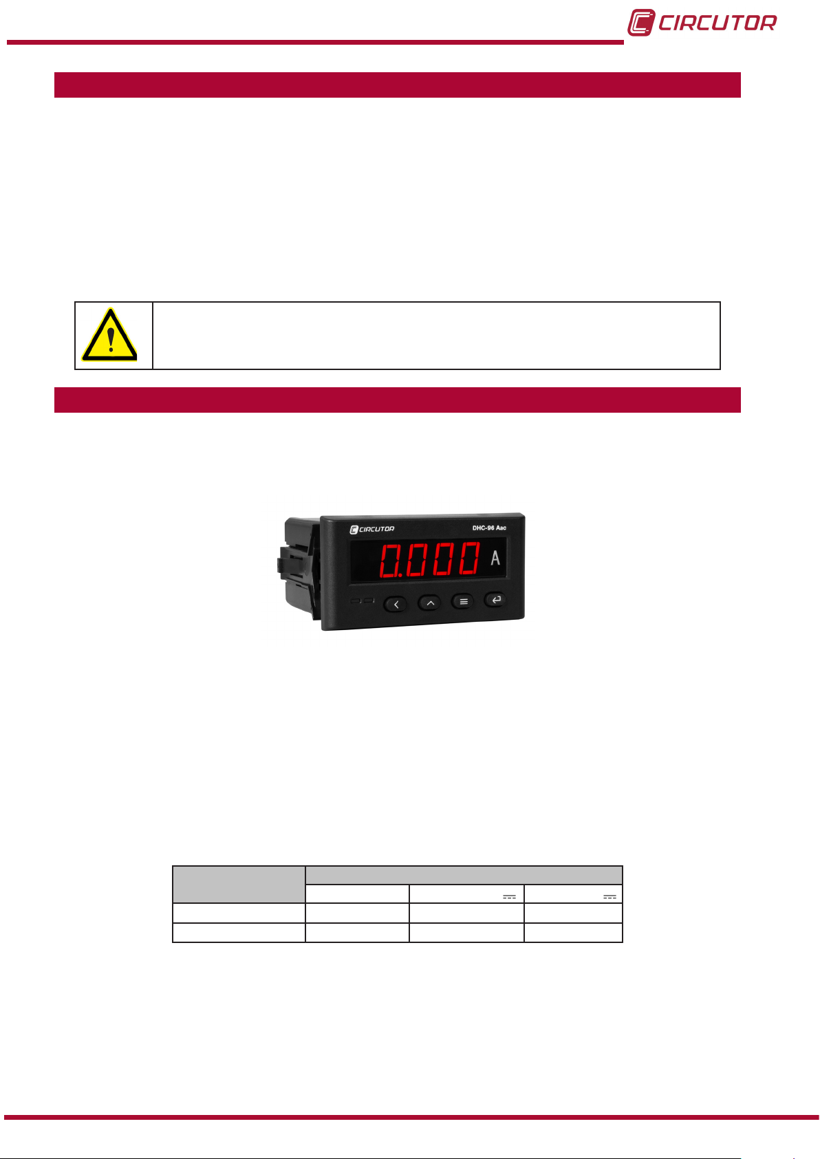
2�- PRODUCT DESCRIPTION
The DHC-96 Aac is a device designed to measure and display the current and frequency AC
single-phase. The device has 2 programmable current scales: 1 A and 5 A.
The device features:
- 4 keys that allow you to browse between the various screens and program the device.
- LED display, displays all parameters.
- 2 fully programmable relay outputs
- 2 digital inputs.
- 1 programmable analog output
- Communications RS-485.
Instruction Manual
Model
M22358
M223580030000
Table 3:DHC-96 Aac list of models�
Power Supply
80 ��� 270 V ~ 80 ��� 270 V 18 �� 36 V
- -
-
7
Page 8
DHC-96 Aac
3�- DEVICE INSTALLATION
3.1.- PRIOR RECOMMENDATIONS
In order to use the device safely, it is critical that individuals who handle it follow
the safety measures set out in the standards of the country where it is being used,
use the necessary personal protective equipment, and pay attention to the various warnings indicated in this instruction manual.
The DHC-96 Aac device must be installed by authorised and qualied staff.
The power supply plug must be disconnected and measuring systems switched off before
handling, altering the connections or replacing the device. It is dangerous to handle the device
while it is powered.
Also, it is critical to keep the cables in perfect condition in order to avoid accidents, personal
injury and damage to installations.
The device’s functionality is limited to the category of measuring voltage or specic current
values.
The manufacturer of the device is not responsible for any damage resulting from failure by the
user or installer to heed the warnings and/or recommendations set out in this manual, nor for
damage resulting from the use of non-original products or accessories or those made by other
manufacturers.
If an anomaly or malfunction is detected in the device, do not use it to take any measurements.
Disconnect the device from the power supply (device and measuring system
power supply) before maintaining, repairing or handling the device's connections.
Please contact the after-sales service if you suspect that there is an operational
fault in the device.
8
Instruction Manual
Page 9
DHC-96 Aac
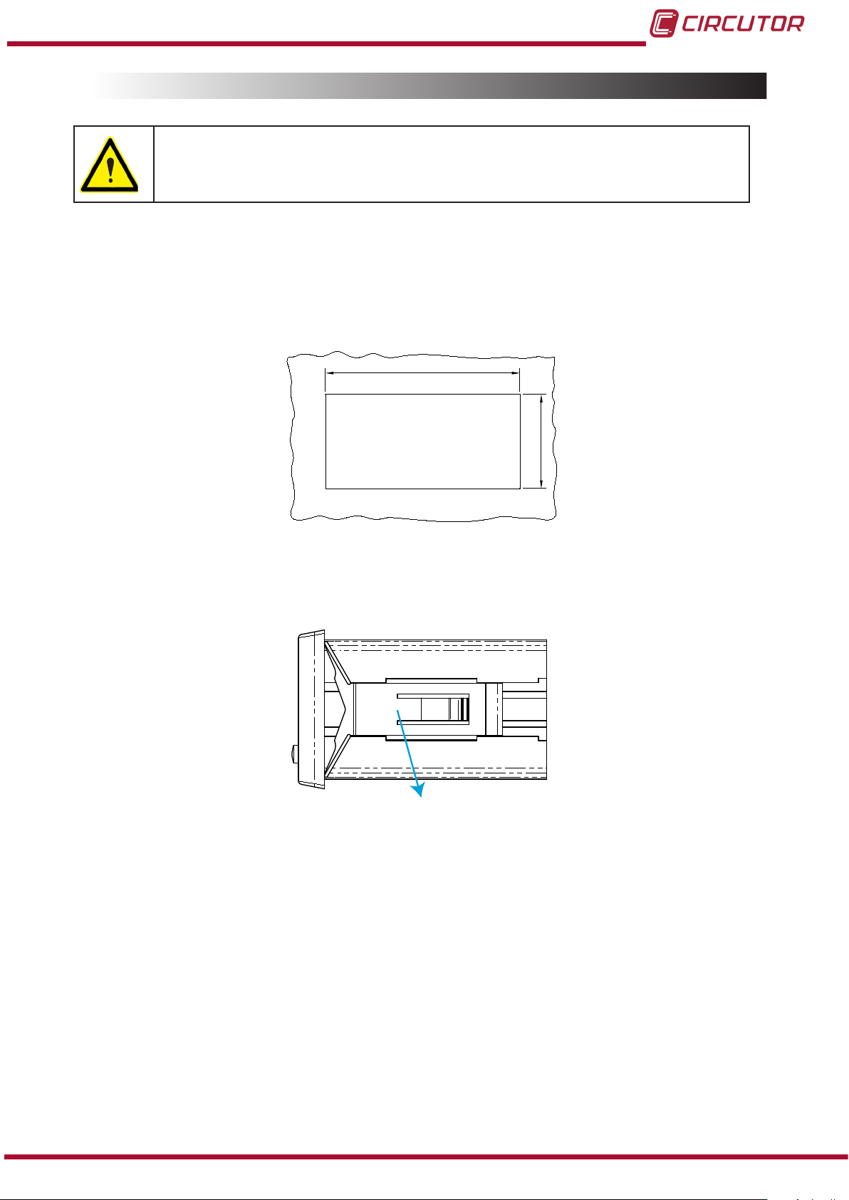
3.2.- INSTALLATION
Terminals, opening covers or removing elements can expose parts that are
hazardous to the touch while the device is powered. Do not use the device
until it is fully installed.
The device should be installed inside an electric panel or enclosure, and panel-mounted.
To install it, take the following steps:
1�- Make a cut in the panel, according to the dimensions in Figure 1�
91
Figure 1: Cut in the panel�
2�- Remove the device’s xing clips (Figure 2).
Clip de jación / Fixing clip
Figure 2: Installation�
44
3�- Insert the device into the cut in the panel.
4�- Fit the xing clips until the device is xed to the panel.
The device should be connected to a power circuit protected by a fuse with a maximum nominal
current of 0�25 A.
Instruction Manual
9
Page 10
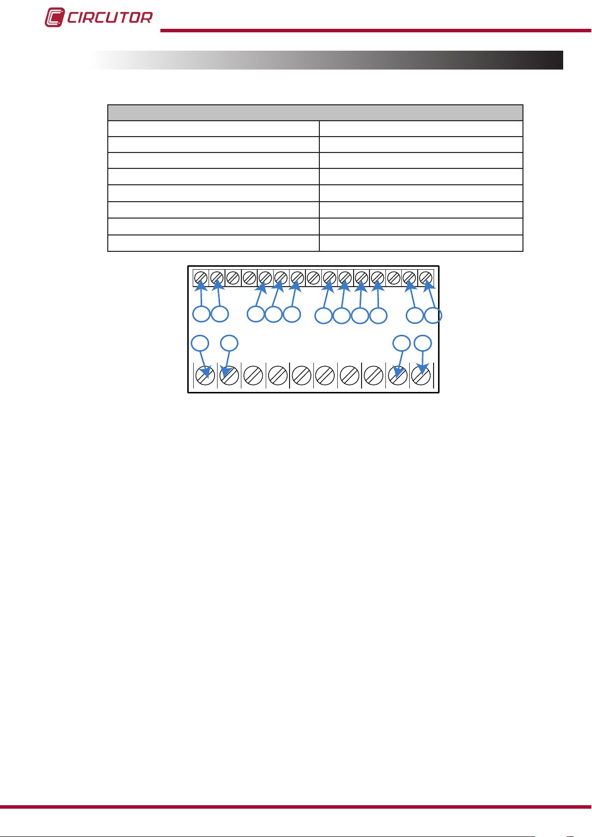
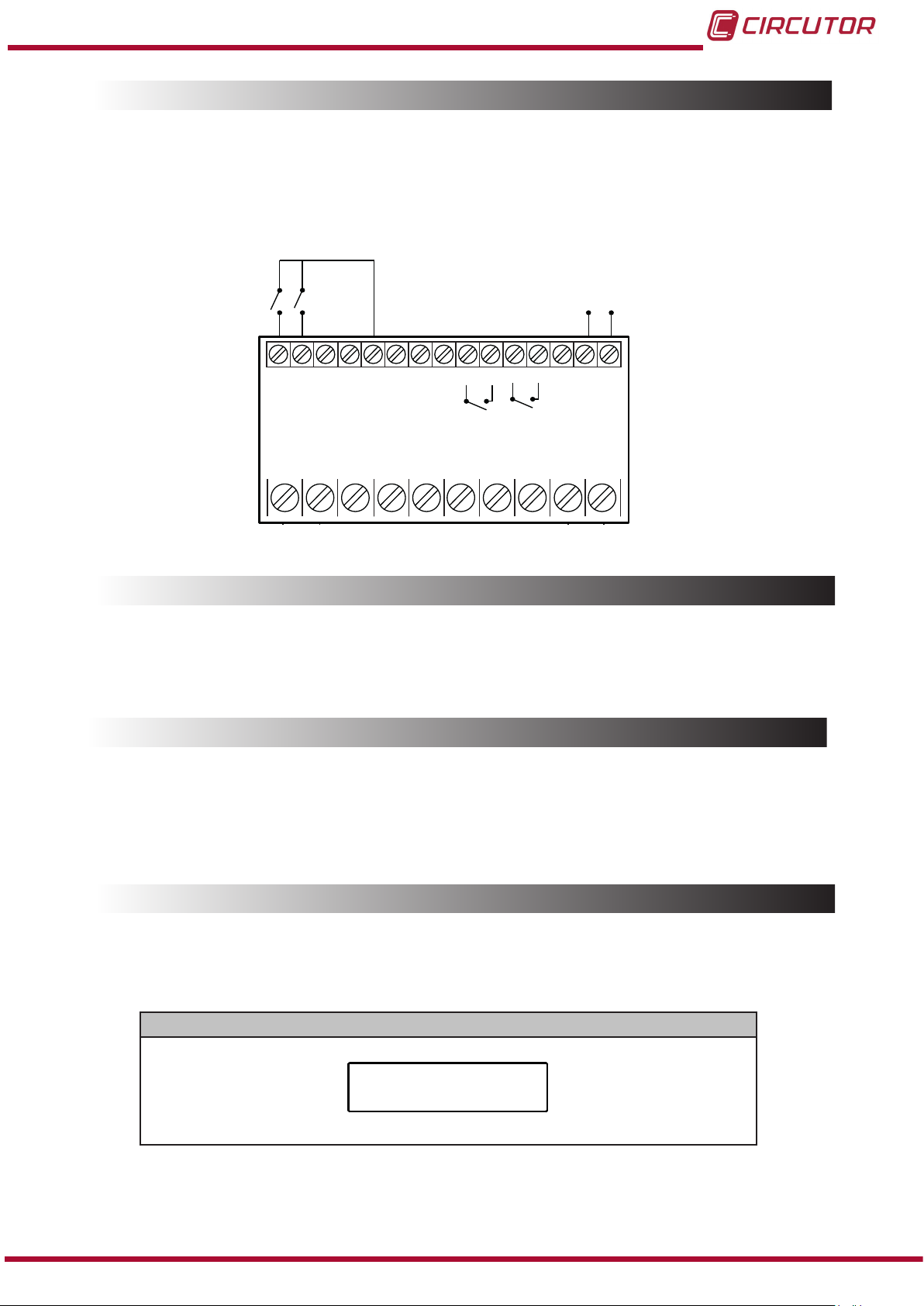
3.3.- DEVICE TERMINALS
Table 4:List of terminals of the DHC-96 Aac�
Device terminals
1 : L, Auxiliary power supply. 31: Alarm output 2, relay (Common)
2: N, Auxiliary power supply. 32: Alarm output 2, relay (NO)
4: Current measurement input 58: A, RS-485
5: Current measurement input 59: B, RS-485
15: -, Analog output
16: +, Analog output
70: Common digital input
71: Digital input 1
28: Alarm output 1, relay (Common) 72: Digital input 2
29: Alarm output 1, relay (NO)
DHC-96 Aac
71
72
71 72
1
1 2
59
70
58
58
59
70
2
Figure 3:Terminals of the DHC-96 Aac�
28
28 29
29
31
31
32 1615
32
5
5
15 16
4
4
Note: Before disconnecting the current measurement connection cables, make sure that you
disconnect the transformer’s primary cable and bridge the secondary.
10
Instruction Manual
Page 11
DHC-96 Aac
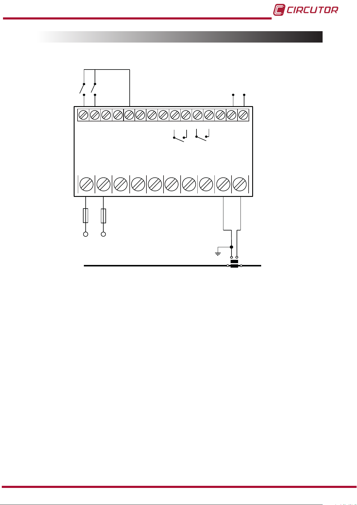
3.4.- CONNECTION DIAGRAM
Entradas Digitales
Digital inputs
Salida Analógica
Analog output
+-
1 2
72 58 28 29 31 32 1615
C
70 5971
B A
RS-485
1 2
Salida de relés
Relay output
1 2
1 2
Alimentación Auxiliar
Power Supply
I
45
S1S2
P2
P1
Figure 4: Current measurement DHC-96 Aac�
If the current being measured is higher than the nominal input current, 5A, a current transformer
should be connected to the device.
If more than one device is connected to the current transformer, it is necessary to connect them
in series.
Instruction Manual
11
Page 12
DHC-96 Aac
4�- OPERATION
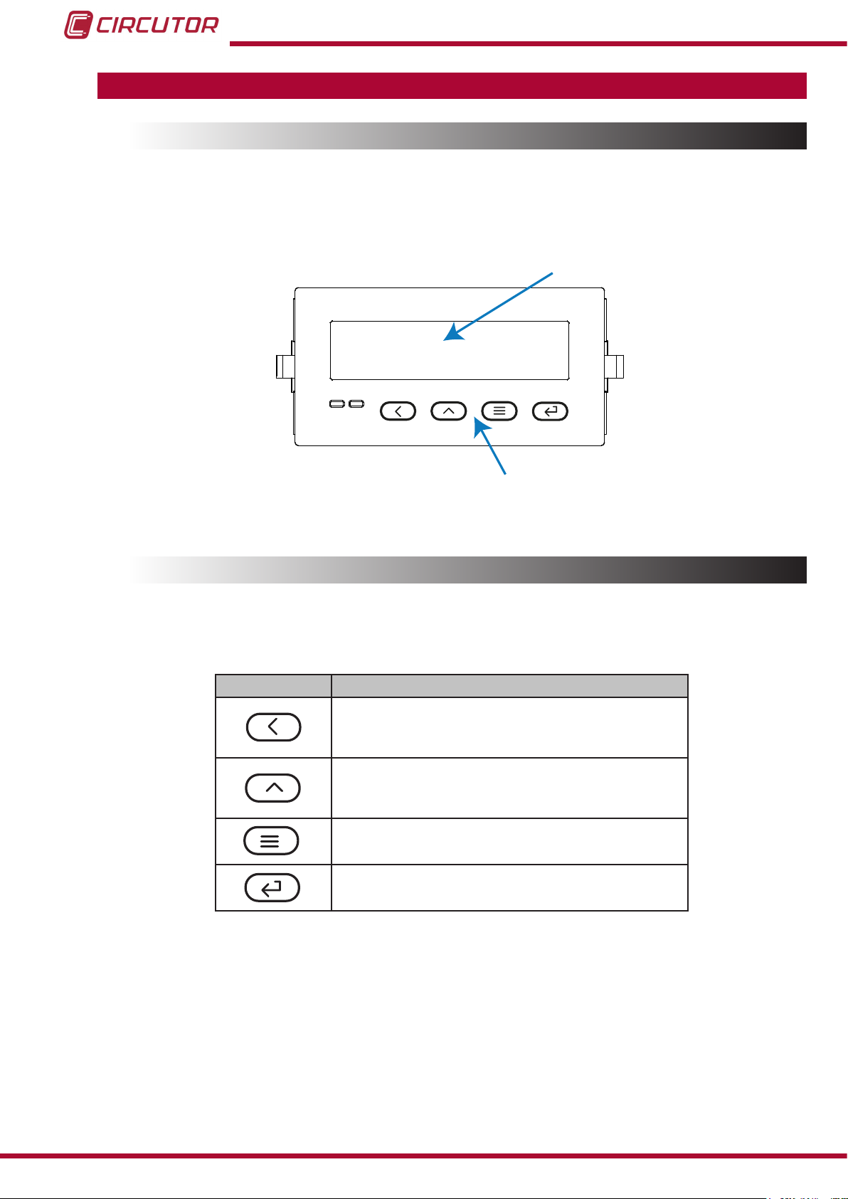
4.1.- DISPLAY
The device features a 5-digit LED display, which is used to display the measured parameters
and to congure these parameters
Display
00000
Keyboard
Figure 5: Display DHC-96�
4.2.- KEYBOARD FUNCTIONS
The DHC-96 Aac features 4 keys to display and congure the device, Figure 5.
Table 5: Keyboard functions�
Key Keystroke
Previous screen
In the conguration menu:
Scroll through the digits
Next screen
In the conguration menu:
Increase the value of the digit
Long keystroke (> 3s):
Enter in conguration menu
In the conguration menu:
Jump to the next level / Conrm an operation
12
Instruction Manual
Page 13
5.000
DHC-96 Aac
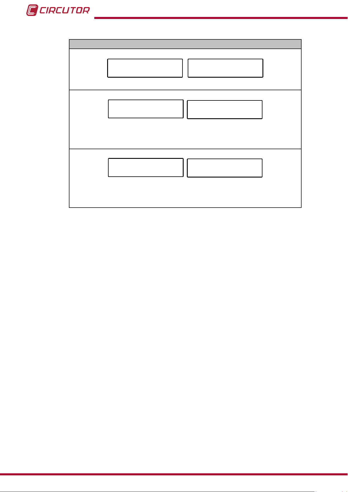
4.3.- RELAY OUTPUTS
The device features two programmable relay outputs (terminals 28, 29, 31 and 32, as shown in
Figure 6) that can be programmed as remote control signals or alarms in the setup menu (“5.4.-
RELAY OUTPUT 1” and “5.5.- RELAY OUTPUT 2”).
Entradas Digitales
Digital inputs
Salida Analógica
Analog output
+-
1 2
C
70 5971
B A
RS-485
1 2
Salida de relés
Relay output
45
4.4.- ANALOG OUTPUT
72 58 28 29 31 32 1615
1 2
Figure 6: Relay outputs, digital inputs and Analog output�
The device has an analog output (terminals 15 and 16 of Figure 6) programmable through the
conguration menu (“5.3.- ANALOG OUTPUT”)
4.5.- ENTRADAS DIGITALES
The device has two digital inputs (terminals 70, 71 and 72 of Figure 6). The relay outputs can be
activated depending on the value of the digital inputs (See “5.4.- RELAY OUTPUT 1” and “5.5.-
RELAY OUTPUT 2”)
4.6.- DISPLAY
The DHC-96 Aac features 4 display screens, Table 6.
Current
Instruction Manual
Table 6: Display menu�
Display menu
13
Page 14
F
50.00
Frequency
di
12
do
12
DHC-96 Aac
Table 6 (Continuation) : Display menu�
Display menu
Status of digital inputs:
1, status of the digital input 1: ashes when the input is activated
2, status of the digital input 2: ashes when the input is activated
Status of the relay outputs:
1, status of the relay output 1: ashes when the relay is activated
2, status of the relay output 2: ashes when the relay is activated
If the current value measured by the device is higher than a % of the nominal value, the device
can make the digits on the display start ashing, in the form of a light alarm. See “5.6.3.- LIGHT
ALARM”
14
Instruction Manual
Page 15

DHC-96 Aac
5�- CONFIGURATION
Press and hold the key for more than 3 seconds to enter the conguration menu of the
device.
The conguration of the device is organized in different menus, Figure 7.
5.000
>3s
rEAd
inPt
ñ- ñ-
Conn
Ao-1
do-1
ProG
Conguration of
the input
Communications
Analog output
Relay output 1
do-2
SEt
Relay output 2
Conguration of
the display
Software version
uEr
Figure 7: Conguration menu of the DHC-96 Aac�
From any screen of the conguration menus, if no key is pressed for 4 minutes, the device
leaves the conguration menu and returns to the display screen.
Note: In “ANNEX A.- CONFIGURATION MENU” you can see the complete conguration menu.
Instruction Manual
15
Page 16

DHC-96 Aac
On the rEAd screen, press the , key to access the conguration menu in the display
mode, i.e., the conguration parameters cannot be modied.
On the rEAd screen, press the or keys to access the conguration menu in the
programming mode, i.e., the conguration parameters can be modied.
rEAd
ProG
CodE
0000
inPt
Figure 8: Access the conguration menu in the programming mode.
Before accessing the conguration menu, it is necessary to enter the access password.
CodE
Figure 9: Access password�
Use the , key to modify the value of the ashing digit
When the desired value is shown on the screen, press the key to skip the digit.
Default password: 0001
0000
Note : The password can be modied, see “5.6.1.- PASSWORD OF ACCESS”�
To validate the data, press the key.
If the password entered is incorrect, the Errmessage will appear for a few seconds and the
device will return to the password conguration screen, Figure 9.
16
Instruction Manual
Page 17

inPt
DHC-96 Aac
5.1.- CONFIGURATION OF THE INPUT
Figure 10, shows the main screen of the input conguration menu, from which the primary
current and secondary current are congured.
Figure 10: Input conguration menu, main screen.
Press the key to open the conguration menu.
inPt
in i
Unt. i
in 2
Unt.2
Figure 11:Input conguration menu.
5�1�1�- PRIMARY CURRENT
This screen is used to congure the value of the primary current.
1.000
oFF
5.000
oFF
in i
Use the , key to modify the value of the ashing digit
When the desired value is shown on the screen, press the key to skip the digit.
When you reach the last digit and press the key, you select the position of the decimal
Instruction Manual
1.000
17
Page 18

point. Use the to modify the decimal point.
Minimum conguration value: 0.
Maximum conguration value: 9999.
To validate the data, press the key.
Use the and keys to browse the conguration screens of the menu.
5�1�2�- UNITS OF THE PRIMARY CURRENT
This screen is used to congure the units of the primary current.
DHC-96 Aac
Unt. i
Use the ,key to browse the different options:
oFF, the unit of the primary current is A.
on, the unit of the primary current is kA.
To validate the data, press the key.
Use the and keys to browse the conguration screens of the menu.
5�1�3�- SECONDARY CURRENT
This screen is used to congure the value of the secondary current.
in 2
oFF
5.000
18
Use the and keys at the same time to congure the value.
Use the ,key to browse the different options:
5.000, for the current scale of 0 ... 5 A.
1.000, for the current scale of 0 ... 1 A.
To validate the data, press the key.
Use the and keys to browse the conguration screens of the menu.
Instruction Manual
Page 19

DHC-96 Aac
5�1�4�- UNITS OF THE SECONDARY CURRENT
Note: This parameter cannot be modied.
Unt.2
Use the and keys to browse the conguration screens of the menu.
5�1�5�- SAVE CONFIGURATION
To save the conguration of the device, press the key, until the main screen of the input
conguration menu is opened, Figure 10.
Press the key again to show the validation screen.
SAuE
Use the ,key to browse the different options:
no, exit the conguration without saving the changed values.
YES, save the changed conguration values.
oFF
no
Press the key to validate the data and exit the conguration menu.
Instruction Manual
19
Page 20

Conn
--
DHC-96 Aac
5.2.- RS-485 COMMUNICATIONS
Figure 12, shows the main screen of the communications menu, where the parameters of the
RS-485 communications are congured.
Figure 12: RS-485 communications menu, main screen�
Press the key to open the conguration menu.
--
Conn
Addr
bAUd
dAtA
Figure 13:RS-485 communications menu
5�2�1�- MODBUS ADDRESS
This screen is used to congure the modbus address of the device.
Addr
0001
9600
n.8.1
0001
Use the , key to modify the value of the ashing digit
When the desired value is shown on the screen, press the key to skip the digit.
Minimum conguration value: 1
Maximum conguration value: 247.
To validate the data, press the key.
Use the and keys to browse the conguration screens of the menu.
20
Instruction Manual
Page 21

DHC-96 Aac
5�2�2�- BAUD RATE
In this screen, the baud rate of RS-485 communications is selected.
bAUd 9600
Use the ,key to browse the different options:
2400, 9600 bps.
4800, 9600 bps.
9600, 9600 bps.
19.20, 19200 bps.
To validate the data, press the key.
Use the and keys to browse the conguration screens of the menu.
5�2�3�- DATA FORMAT
This screen is used to congure the data format.
dAtA
Use the ,key to browse the different options:
n.8.1, no parity, 8 data bits, 1 stop bit
o.8.1, odd parity, 8 data bits, 1 stop bit
E.8.1, even parity, 8 data bits, 1 stop bit
n.8.1
n.8.2, no parity, 8 data bits, 2 stop bit
To validate the data, press the key.
Use the and keys to browse the conguration screens of the menu.
5�2�4�- SAVE CONFIGURATION
To save the conguration of the device, press the key, until the main screen of the input
conguration menu is opened, Figure 10.
Press the key again to show the validation screen.
Instruction Manual
21
Page 22

DHC-96 Aac
SAuE
Use the ,key to browse the different options:
no, exit the conguration without saving the changed values.
YES, save the changed conguration values.
Press the key to validate the data and exit the conguration menu.
5.3.- ANALOG OUTPUT
Figure 14, shows the main screen of the analog output menu.
no
A0-1
Figure 14: Analog output menu, main screen�
Press the key to open the conguration menu.
A0-1
-
nodE
ds
FS
Figure 15:Analog output menu�
5�3�1�- TYPE OF OUTPUT
In this screen the output type of the analog output is congured
4-20
0.000
5.000
22
-
nodE 4-20
Instruction Manual
Page 23

DHC-96 Aac
Use the and keys at the same time to congure the value.
Use the ,key to browse the different options:
4-20, Current output 4 ... 20 mA
0-20, Current output 0 ... 20 mA
12.20, Current output 4 ...12 ... 20 mA
To validate the data, press the key.
Use the and keys to browse the conguration screens of the menu.
5�3�2�- READING FOR THE START OF THE ANALOG OUTPUT
In this screen, the reading value from which the analog output is started is congured.
ds
Use the , key to modify the value of the ashing digit
When the desired value is shown on the screen, press the key to skip the digit.
Minimum conguration value: 0.000
Maximum conguration value: 0.5 x Secondary current.
Note: FS (End of the analog output) - DS (Start of the analog output) ≥ 500
To validate the data, press the key.
Use the and keys to browse the conguration screens of the menu.
5�3�3�- READING FOR THE END OF THE ANALOG OUTPUT
In this screen, the reading value from which the analog output ends is congured.
0.000
FS 5.000
Use the , key to modify the value of the ashing digit
When the desired value is shown on the screen, press the key to skip the digit.
Minimum conguration value: 0.5 x Secondary current.
Maximum conguration value: 1.2 x Secondary current.
Note: FS (End of the analog output) - DS (Start of the analog output) ≥ 500
Instruction Manual
23
Page 24

DHC-96 Aac
To validate the data, press the key.
Use the and keys to browse the conguration screens of the menu.
5�3�4�- SAVE CONFIGURATION
To save the conguration of the device, press the key, until the main screen of the input
conguration menu is opened, Figure 10.
Press the key again to show the validation screen.
SAuE
Use the ,key to browse the different options:
no, exit the conguration without saving the changed values.
YES, save the changed conguration values.
Press the key to validate the data and exit the conguration menu.
no
24
Instruction Manual
Page 25

ñ-
DHC-96 Aac
5.4.- RELAY OUTPUT 1
Figure 16, shows the main screen of the conguration menu of relay output 1.
do-1
Figure 16: Conguration menu of relay output 1, main screen.
Press the key to open the setup menu.
do-1
ññnodE
ñ-
tinE
ñ-
itEn
dELy
uALE
oFF
0000
i--H
0010
000.0
HyS
Figure 17:Conguration menu of relay output 1.
5�4�1�- RELAY MODE
This screen is used to congure the operating mode of relay 1.
ñnodE
Use the key to browse the different options:
Instruction Manual
000.5
oFF
25
Page 26

oFF, relay output 1 is disabled.
ñ-
-
rEn, remote control output.
ALr, alarm output.
To validate the data, press the key.
Use the and keys to browse the conguration screens of the menu.
5�4�2�- RELAY PULSE DURATION
The alarm relay can behave in 2 different ways:
1�- The relay is activated when the alarm is triggered and is deactivated when the alarm
is deactivated.
2�- The relay is activated when the alarm is triggered and is deactivated after a programmed period of time, even though the alarm condition has not been cancelled.
DHC-96 Aac
This screen is used to congure the programmed time, i.e., the relay pulse duration.
To make the relay operate in mode no� 1, program the value to 0.
ñ-
tinE
Use the , key to modify the value of the ashing digit
When the desired value is shown on the screen, press the key to skip the digit.
Minimum conguration value: 0 x 0.1 s
Maximum conguration value: 9999 x 0.1 s
Example: Use program 0050 to congure a value of 5 s.
To validate the data, press the key.
Use the and keys to browse the conguration screens of the menu.
0000
26
5�4�3�- ALARM PARAMETER
This screen is used to congure the parameter that will be used to activate the alarm.
itEn
Use the key to browse the different options:
F--H, Active alarm when the frequency is higher than the alarm value.
i--H
Instruction Manual
Page 27

DHC-96 Aac
i--H, Active alarm when the current is higher than the alarm value.
F--L, Active alarm when the frequency is less than the alarm value.
i--L, Active alarm when the current is less than the alarm value.
di1H, Active alarm when digital input 1 is connected.
di2H,Active alarm when digital input 2 is connected.
di1L, Active alarm when digital input 1 is disconnected.
di2L,Active alarm when digital input 2 is disconnected.
To validate the data, press the key.
Use the and keys to browse the conguration screens of the menu.
5�4�4�- CONNECTION DELAY
This screen is used to congure the alarm connection delay.
dELy
Use the , key to modify the value of the ashing digit
When the desired value is shown on the screen, press the key to skip the digit.
Minimum conguration value: 0 x 0.1 s
Maximum conguration value: 9999 x 0.1 s
Example: Use program 0050 to congure a value of 5 s.
To validate the data, press the key.
Use the and keys to browse the conguration screens of the menu.
5�4�5�- ALARM VALUE
The value after which the alarm will be activated is congured on this screen.
0010
uALE
Use the , key to modify the value of the ashing digit
When the desired value is shown on the screen, press the key to skip the digit.
Minimum conguration value: 0
Maximum conguration value: 9999
Instruction Manual
000.0
27
Page 28

DHC-96 Aac
To validate the data, press the key.
Use the and keys to browse the conguration screens of the menu.
5�4�6�- HYSTERESIS
This screen is used to congure the hysteresis value, i.e., the difference between the alarm
connection and disconnection value.
HyS
Use the , key to modify the value of the ashing digit
When the desired value is shown on the screen, press the key to skip the digit.
Minimum conguration value: 0
Maximum conguration value: 9999
To validate the data, press the key.
Use the and keys to browse the conguration screens of the menu.
5�4�7�- SAVE CONFIGURATION
To save the conguration of the device, press the key until the main screen of the relay
output 1 conguration menu is opened, Figure 16.
000.5
Press the key again to show the validation screen.
SAuE
Use the key to browse the different options:
no,exit the conguration without saving the changed values.
YES, save the changed conguration values.
Press the key to validate the data and exit the conguration menu.
no
28
Instruction Manual
Page 29

SEt
DHC-96 Aac
5.5.- RELAY OUTPUT 2
Figure 18, shows the main screen of the conguration menu of relay output 2.
do-2
Figure 18:Conguration menu of relay output 2, main screen.
The conguration is the same as for alarm relay 1, see “5.4.- RELAY OUTPUT 1”.
5.6.- CONFIGURATION OF THE DISPLAY
Figure 19, shows the main screen of the conguration menu of the display.
Figure 19: Conguration menu of the display, main screen.
Press the key to open the conguration menu.
SEt
CodE
Alr
Figure 20:Conguration menu of the display.
0001
L3LiGH
120.0
5�6�1�- PASSWORD OFF ACCESS
This screen is used to congure the value of the password used to access the conguration
menu in the programming mode.
0000
Instruction Manual
CodE
29
Page 30

DHC-96 Aac
Use the , key to modify the value of the ashing digit
When the desired value is shown on the screen, press the key to skip the digit.
Minimum conguration value: 0
Maximum conguration value: 9999
To validate the data, press the key.
Use the and keys to browse the conguration screens of the menu.
5�6�2�- BRIGHTNESS OF THE DISPLAY
The brightness of the display is congured on this screen.
LiGH
Use the , key to browse the different options: the display has 5 brightness levels, from L1
to L5.
To validate the data, press the key.
Use the and keys to browse the conguration screens of the menu.
5�6�3�- LIGHT ALARM
If the current value measured by the device is higher than a % of the nominal value, the device
can make the digits on the display start ashing, in the form of a light alarm.
Alr
L3
120.0
30
Use the , key to modify the value of the ashing digit.
When the desired value is shown on the screen, press the key to skip the digit.
Minimum conguration value: 30.0%
Maximum conguration value: 120.0%
Note: If the a value of 0 is programmed, the light alarm will be deactivated.
To validate the data, press the key.
Use the and keys to browse the conguration screens of the menu.
Instruction Manual
Page 31

DHC-96 Aac
5�6�4�- SAVE CONFIGURATION
To save the conguration of the device, press the key until the main screen of the conguration menu of the display is opened, Figure 19.
Press the key again to show the validation screen.
SAuE
Use the ,key to browse the different options:
no, exit the conguration without saving the changed values.
YES, save the changed conguration values.
Press the key to validate the data and exit the conguration menu.
5.7.- SOFTWARE VERSION
The software version of the device is shown in the display mode.
uEr
no
3014
Instruction Manual
31
Page 32

DHC-96 Aac
6�- RS-485 COMMUNICATIONS
The DHC-96 devices have one RS-485 communications port,with communications protocols:
MODBUS RTU ® .
6.1.- CONNECTIONS
The RS-485 cable must be wired with twisted pair cable with mesh shield, with a maximum
distance between the DHC-96 and the master device of 1200 metres.
A maximum of 32 DHC-96 devices can be connected to this bus.
Use an intelligent RS-232 to RS-485 network protocol converter to establish the
communications with the master device.
PC
RS-232 / USB / Ethernet / Profibus ...
RS-232
USB
Ethernet
Profibus
...
RS-485
RS-485
B(-) A(+)
72 58 28 29 31 32 1615
70 5971
B A
RS-485
72 58 28 29 31 32 1615
70 5971
B A
RS-485
32
1 2
11
14
1 2
11
14
Figure 21: RS-485 Connection diagram�
Note: Default values of the RS-485 communication : 19200 bps, No parity, 8 data bits and 1
stop bit.
Instruction Manual
Page 33

DHC-96 Aac
6.2.- MODBUS PROTOCOL
In the Modbus protocol, the DHC-96 device uses the RTU (Remote Terminal Unit) mode.
The Modbus functions implemented in the device are as follows:
Function 0x01: Reading a relay.
Function 0x02: Reading input status.
Function 0x03 and 0x04: Reading integer registers.
Function 0x05: Writing a relay.
Function 0x0F: Writing multiples relays
Function 0x10: Writing multiples registers.
6�2�1� READING EXAMPLE : FUNCTION 0x01�
Question: Status of output relays
Address Function
01 01 0000 0002 BDCB
Initial
Register
No� of
Registers
CRC
Address: 01, Peripheral number: 1 in decimal.
Function: 01, Read function.
Initial Register: 0000, on which the reading will start.
No� of Registers: 0002, number of registers read.
CRC: BDCB, CRC Character.
Response:
Address Function
01 01 01 03 1189
No� of
Bytes
Register
No� 1
CRC
Address: 01, Responding peripheral number: 1 in decimal.
Function: 01, Read function.
No� of bytes: 01, No. of bytes received.
Registre: 03, in binary it is: 0000 0011, output relays 1 and 2 closed.
CRC:1189, CRC.Character.
6�2�2� EXAMPLE OF OPERATION OF THE REMOTE CONTROL: FUNCTION 0X05�
Question: Activate the output of relay 1, programmed to work in remote control mode.
Address Function
01 05 0000 FF00 8C3A
Initial
Register
Relay action CRC
Address: 01, Peripheral number: 1 in decimal.
Function: 05, Writing a relay
Initial Register: 0000, relay 1 address.
Relay action: FF00, We indicate that we want to close the relay.
CRC: 8C3A, CRC.Character.
Instruction Manual
33
Page 34

Response:
Address Function
01 05 0000 FF00 8C3A
Initial
Register
Relay action CRC
6.3.- MODBUS COMMANDS
6�3�1�- MEASUREMENT VARIABLES AND DEVICE STATUS
All the addresses of Modbus memory are in Hexadecimal.
For these variables is implemented the Function 0x03 and 0x04.
Table 7: Modbus memory map (Table 1)
Parameter Format Address Units
Current oat 12 A
Current int 10C 0.001 A
Frequency oat 2C Hz
Frequency int 120 0.01 Hz
DHC-96 Aac
Table 8: Modbus memory map (Table 2)
Parameter Format Address Value
Status of output relays bit [0] - bit [2] bit [32] 100 - 101
Status of digital inputs bit [0] - bit [2] bit [32] 102 - 103
Communications ID int 104 504
6�3�2�- OUTPUT RELAYS
All the addresses of Modbus memory are in Hexadecimal.
For these variables is implemented the Function 0x01, 0x05 and 0x0F�
Table 9: Modbus memory map (Table 3)
Parameter Format Address Value
Output relay 1 bit 0000 0: open, 1: closed
Output relay 2 bit 0000 0: open, 1: closed
6�3�3�- DIGITAL INPUTS
0: open
1: closed
0: open
1: closed
34
All the addresses of Modbus memory are in Hexadecimal.
For these variables is implemented the Function 0x02�
Table 10: Modbus memory map (Table 4)
Parameter Format Address Value
Digital input 1 bit 0000 0: open, 1: closed
Digital input 2 bit 0000 0: open, 1: closed
Instruction Manual
Page 35

DHC-96 Aac
6�3�4�- REMOTE CONTROL OUTPUT (Relay output)
All the addresses of Modbus memory are in Hexadecimal.
For these variables is implemented the Function 0x05 and 0x0F�
Table 11: Modbus memory map (Table 5)
Parameter Format Address Value
Remote control, Output relay 1 bit 0000 0: open, 1: closed
Remote control, Output relay 2 bit 0001 0: open, 1: closed
6�3�5�- DEVICE CONFIGURATION VARIABLES
All the addresses of Modbus memory are in Hexadecimal.
For these variables is implemented the Function 0x10�
6.3.5.1. Conguration of the input
Table 12:Modbus memory map : Conguration of the input
Conguration of the input
Variable Format Address Valid data margin
Primary current int 809 1 ... 9999
Decimal point of the primary current int 80A
Units of the primary current int 806 0: A - 1: kA
0: xxxx - 1: xxx.x -
2: xx.xx - 3: x.xxx
6�3�5�2� RS-485 communications
Table 13:Modbus memory map : RS-485 communications
RS-485 communications
Variable Format Address Valid data margin
Modbus address int 802 1 ... 247
Baud rate int 803
Data format int 804
0: n,8,1 : no parity, 8 data bits, 1 stop bit
1: o,8,1 : odd parity, 8 data bits, 1 stop bit
2: e,8,1 : even parity, 8 data bits, 1 stop bit
3: n,8,2 : no parity, 8 data bits, 2 stop bit
0: 2400 bps - 1: 4800 bps -
2: 9600 bps - 3: 19200 bps
6�3�5�3� Analog output
Table 14:Modbus memory map : Analog output
Analog output
Variable Format Address Valid data margin
Type of output int 814
Reading for the end of the analog output (fs)
Reading for the start of the analog output (ds)
Instruction Manual
int 815 0.5 x SC
int 816 0 ≤ ds ≤ 0.5 x SC
1: Current output
9: Frequency output
(1)
≤ fs ≤ 1.2 x SC
(1)
(1)
35
Page 36

Table 14 (Continuation): Modbus memory map : Analog output
Analog output
Variable Format Address Valid data margin
Type of output int 817
(1)
SC: Secondary current.
6�3�5�4� Relays outputs
Table 15:Modbus memory map : Relay outputs�
Relay outputs
Variable Format Address Valid data margin
Relay 1 mode int 820
Relay 2 mode int 826
Relay 1 pulse duration int 821
Relay 2 pulse duration int 827
Alarm parameter of relay 1 int 822 3: Upper current alarm
11: Upper frequency alarm
12: Alarm when Digital 1 input is connected
13: Alarm when Digital 2 input is connected
Alarm parameter of relay 2 int 828
Relay 1 connection delay int 823
Relay 2 connection delay int 829
Relay 1 alarm value int 824
Relay 2 alarm value int 82A
Relay 1 hysteresis int 825
Relay 2 hysteresis int 82B
19: Lower current alarm
27: Lower frequency alarm
28: Alarm when Digital 1 input is disconnected
29: Alarm when Digital 2 input is disconnected
0: output is disabled.
2: remote control output.
DHC-96 Aac
0: 4 ... 20 mA
1: 0 ... 20 mA
2: 4... 12 ... 20 mA
1: alarm output
0 ... 9999 ( x 0.1 s)
0 ... 9999 ( x 0.1 s)
0 ... 9999
0 ... 9999
36
6.3.5.5. Conguration of the display
Table 16:Modbus memory map : Conguration of the display
Conguration of the display
Variable Format Address Valid data margin
Rotation of the display screen int 800
Brightness of the display int 801 0 ... 4
Light alarm int 805 300 ... 1200 (x 0.1%)
0: the screens don’t rotate
1 ... 60 s
Instruction Manual
Page 37

DHC-96 Aac
7�- TECHNICAL FEATURES
AC Power supply
(2)
Rated voltage 80 ... 270 V ~
Frequency 50 / 60 Hz
Consumption 2.6 ... 4.9 VA
Installation category CAT III 300 V
DC Power supply
(2)
Rated voltage 80 ... 270 V 18 ... 36 V
Consumption 1.5 ... 1.6 W 1.2 W
Installation category CAT III 300 V
(2)
Depending on model :
Model
M22358
M223580030000
80 ��� 270 V ~ 80 ��� 270 V 18 ��� 36 V
- -
Power supply
-
Current measurement circuit
Nominal current (In) 1 A ~ / 5 A ~
Frequency measurement margin 45 ... 65 Hz
Overload 1.2 In continuous, 10 In Instantaneous (5s)
Consumption < 0.2 VA
Impedance < 20 mΩ
Installation category CAT III 300V
Measurement accuracy
Current measurement 0.5%
Relays outputs
Quantity 2
Contact capacity (resistive) CA: 5A / 250 V~ , CC: 5A / 30 V
Max� voltage open contacts 277 V~
Maximum current 5 A ~
Maximum switching power 1385 VA
Electrical life (250 V~ / 5A) 1x10
Mechanical life 5x10
5
6
Digital inputs
Quantity 2
Type Potential free contact
Insulation 2000 V~
Maximum short-circuit current 3.3 mA
Maximum voltage in open circuit 17 V
Analog output
Quantity 1
Maximum internal voltage 17 V
Linearity 0.5 %
Nominal output range 0-20 mA, 4-20 mA, 4-12-20 mA (Programmable)
Maximum load resistor 350 Ω
Instruction Manual
37
Page 38

RS-485 communications
Communications protocol Modbus RTU
Baud rate 2400 - 4800 - 9600 - 19200 bps
Data bits 8
Stop bits 1 - 2
Parity without, even, odd
User interface
Display LED 5 digits
Keyboard 4 keys
Environmental features
Operating temperature -40ºC ... +70ºC
Storage temperature -40ºC ... +85ºC
Relative humidity ≤ 95%
Maximum altitude 2000 m
Protection degree
Pollution degree
Front : IP54, Rear case: IP20
2
DHC-96 Aac
Mechanical features
Power supply and Measurement
Terminals : 1, 2, 4, 5
≤ 1 mm
2
≤ 0.5 Nm PZ1
Analog output, Relay outputs, RS-485, Digital inputs
Terminals : 15, 16, 28, 29, 31, 32, 58, 59, 70, 71, 72
≤ 2.5 mm
2
0.5 ... 0.6 Nm PZ0
Dimensions Figure 22 (mm)
Weight 236 g.
Surround pc + abs
Standards
Electromagnetic compatibility (EMC) -- Part 4-2: Testing and measurement
techniques - Electrostatic discharge immunity test�
IEC 61000-4-2
Electromagnetic compatibility (EMC)- Part 4-3: Testing and measurement
techniques- Radiated, radio-frequency, electromagnetic eld immunity
IEC 61000-4-3
test
Electromagnetic compatibility (EMC) - Part 4-4: Testing and measurement
techniques - Electrical fast transient/burst immunity test
Electromagnetic compatibility (EMC) - Part 4-5: Testing and measurement
techniques - Surge immunity test
IEC 61000-4-4
IEC 61000-4-5
Electromagnetic compatibility (EMC) - Part 4-6: Testing and measurement
techniques - Immunity to conducted disturbances, induced by radio-fre-
IEC 61000-4-6
quency elds
Electromagnetic compatibility (EMC) -- Part 4-8: Testing and measurement
techniques - Power frequency magnetic eld immunity test
IEC 61000-4-8
Electromagnetic compatibility (EMC) -- Part 4-11: Testing and measurement techniques - Voltage dips, short interruptions and voltage variations
IEC 61000-4-11
immunity tests
Safety requirements for electrical equipment for measurement, control
and laboratory use -- Part 1: General requirements
IEC 61010-1
38
Instruction Manual
Page 39

DHC-96 Aac
49
96
8 68.5
Figure 22: Dimensions of the DHC-96�
10(max)
81.2
Instruction Manual
39
Page 40

DHC-96 Aac
8�- MAINTENANCE AND TECHNICAL SERVICE
In the case of any query in relation to unit operation or malfunction, please contact the
CIRCUTOR, SA Technical Support Service.
Technical Assistance Service
Vial Sant Jordi, s/n, 08232 - Viladecavalls (Barcelona)
Tel: 902 449 459 ( España) / +34 937 452 919 (outside of Spain)
email: sat@circutor.es
9�- GUARANTEE
CIRCUTOR guarantees its products against any manufacturing defect for two years after the
delivery of the units.
CIRCUTOR will repair or replace any defective factory product returned during the guarantee
period.
• No returns will be accepted and no unit will be repaired or replaced if it is not accompanied by a report indicating the defect detected or the reason for the return.
•The guarantee will be void if the units has been improperly used or the storage, installation and maintenance instructions listed in this manual have not been
followed. “Improper usage” is de ned as any operating or storage condition contrary to the national electrical code or that surpasses the limits indicated in the
technical and environmental features of this manual.
• CIRCUTOR accepts no liability due to the possible damage to the unit or other
parts of the installation, nor will it cover any possible sanctions derived from a possible failure, improper installation or “improper usage” of the unit. Consequently,
this guarantee does not apply to failures occurring in the following cases:
- Overvoltages and/or electrical disturbances in the supply;
- Water, if the product does not have the appropriate IP classi cation;
- Poor ventilation and/or excessive temperatures;
- Improper installation and/or lack of maintenance;
- Buyer repairs or modi cations without the manufacturer’s authorisation.
40
Instruction Manual
Page 41

DHC-96 Aac
10�- CE CERTIFICATE
Instruction Manual
41
Page 42

DHC-96 Aac
42
Instruction Manual
Page 43

DHC-96 Aac
Instruction Manual
43
Page 44

ANNEX A�- CONFIGURATION MENU
5.000
>3s
rEAd
ProG
CodE
DHC-96 Aac
0000
inPt
--
Conn
Ao-1
in i
Unt. i
in 2
Unt.2
Addr
6Aud
dAtA
-
nodE
dS
FS
000.0
oFF
5.000
oFF
0001
2400
n.8.1
4-20
0.000
1.000
Primary current
on
1.000
Units o the secondary
current
Modbus address
4800
o.8.1
Units of the primary
current
Secondary current
9600
E.8.1
0-20 12.20
Reading for the start of the analog output
Reading for the end of the analog output
19.20
n.8.2
Type of output
Baud rate
Data format
do-1
do-2
SEt
-
nodE
-
tinE
itEn
dELy
uALE
Hys
CodE
LiGH
Alr
-
oFF
0000
i--H
0010
000.0
000.5
0001
L1
120.0
-
rEn ALr
Relay pulse duration
F--H
diiH
F--L di1L di2L
Connection delay
Alarm value
Hysteresis
Password o access
L5
Light alarm
Brightness of the
display
Relay mode
di2H
Alarm
parameter
1--L
44
uEr
uEr
3014
Figure 23:Conguration menu DHC-96 Aac
Software version
Instruction Manual
Page 45

DHC-96 Aac
Instruction Manual
45
Page 46

CIRCUTOR, SA
Vial Sant Jordi, s/n
08232 -Viladecavalls (Barcelona)
Tel.: (+34) 93 745 29 00 - Fax: (+34) 93 745 29 14
www.circutor.com central@circutor.com
 Loading...