

Page 1
Before any maintenance, modification to the
ensuring against any accidental
max
min
None
00
Three-phase active power
kW III
16
Three-phase apparent power
kVA III
34
Three-phase current
AIII
36
Current per phase
A1-A2-A3
A-ph
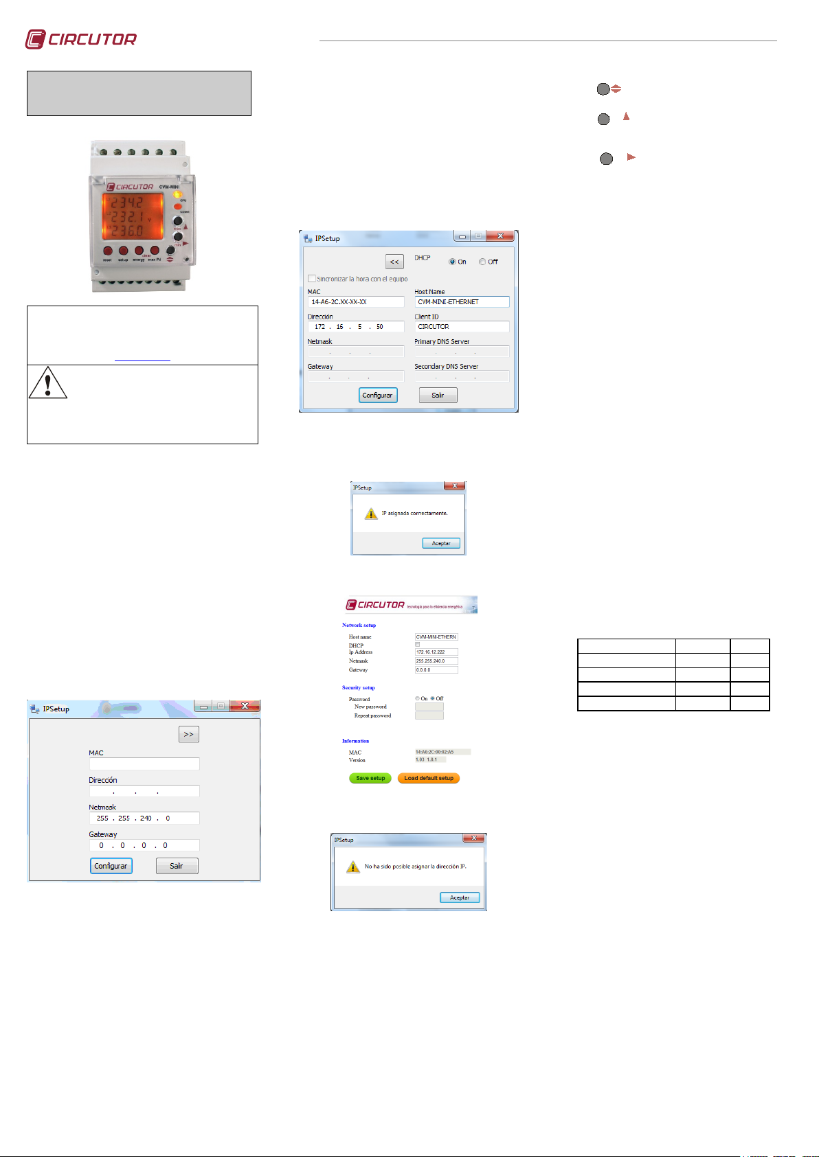
CVM-MINI-Ethernet
POWER ANALYZER
CVM-MINI-Ethernet
This manual is a quick guide to the use and operation of
the CVM-MINI-ITF & CMV-MINI-MC with Ethernet
connection. For more information, the whole manual
may be downloaded from CIRCUTOR's web page:
remain out of service
reconnection. The equipment is designed to be changed quickly
in the event of any breakdown.
The CVM-MINI is an instrument which measures,
calculates and displays the main electrical parameters
for three-phase industrial systems (balanced or
unbalanced). Measurements are in true effective value,
via three AC voltage inputs and three AC. current
inputs. (via
MC version). The parameters measured and calculated
are shown in the variables table, paragraph 7.
1.- INSTALLATIO N
The equipment is mounted on DIN rail. Also the device
has to be provided of an magnetic-thermal switch to be
disconnected. The fuses has to be type gl (IEC 269) or
type M between 0,5 to 2 A.
2.- ETHERNET NETWORK SETUP
The configuration software, IPSETUP.EXE, is available
from the CIRCUTOR Web site. It must be executed
under Windows operative system. Once executed it will
appear the following screen
www.circutor.es
connections, repair, etc., the equipment must be
disconnected from the supply. If any operation or
protection fault is suspected the equipment must
I
/ 5 A or 1 A the ITF version and In 0,25A
n
3.- DHCP IP assignment
To assign the DHCP name, choose this option using
the arrow on the upper right, and select “On”. Once the
configuration fields have been enabled, enter the
“MAC” address that can be seen on the permanent side
label attached to the device, the format of which is
14:A6:2C:XX:XX:XX. In the “Dirección” field, enter an
unused, temporary IP address, which is within the
working range of your computer. In the “Host Name”
field, enter the DHCP name to be assigned to the
equipment. Optionally, the user can configure the
parameters of the “ClientID” field. The default
“VendorID” of the device is CIRCUTOR.
Once the parameters have been configured click on
"Configurar"
If the equipment is detected into the Ethernet network,
it will appear the following screen.
By clicking "Aceptar" the internal setup WEB page of
the equipment will be displayed.
4.- SETTING (SETUP menu)
(Press SETUP key for 5 seconds)
The
on to the next menu.
The
key validates the information and moves
key allows the different options in a
menu to be selected or increases a digit where a
variable is being entered.
The
key is used to move the cursor
among the digits.
The different options are sequentially described below.
4.1.- Voltage transformer primary
On screen the words "SET PriU" appear followed by 6
digits. These allow the voltage transformer primary to be
set (from
1 to 100,000).
4.2.- Voltage transformer secondary
On screen the words "SET SEcU" appear followed by 3 digits.
These allow the voltage transformer secondary to be set (from
1 to 999).
4.3.- Current transformer primary
The display show "SET PriA" followed by 5 digits. These allow
the current transformer primary to be set (from
1 to 10,000).
In the case of using a transforming system type MC1,
introduces the primary of the transformer
corresponding to the relation of the selected physical
wiring. In case of using type MC3, introduces the value
of the primary that appears in the label of the
transformer.
4.4.- Current transformer secondary.
The display show "SET SecA". In the ITF versions, selection is
allowed between 1 and 5 A. In the MC version, this parameter
is not available in the equipment configuration menu.
4.5.- Measurement in 2 or 4 quadrants (power
consumption and/or generation).
On screen the words “
(
2=Power consumption / 4=consumption and
SET QuAd” appear
generation)
4.6.- Setting the Power demand meter:
a) Electrical parameter to control: ("SET Pd Code"):
In the field "MAC" it must be typed the physical address
of the unit using scripts as separator, this data is
showed on to the lateral label of the equipment and the
format is 14:A6:2C:XX:XX:XX.
In to the field "Dirección", type the assigned IP
address to the equipment into the local area network
Into the field "Netmask" type the mask for the network.
In case of routing the equipment in a different network,
setup the field "Gateway" with the IP address of the
device that allows the route. For example, if the
equipment must be accessible from Internet, will be
necessary setup the IP address for the ADSL router
that allows the Internet connection. Also the router will
need convenient programming to allow Internet enroute
and enable the traffic from/to the CVM-MINI-Ethernet.
If it is not the case leave the filed "Gateway" in blank.
If the equipment is not detected on the local network it
will appear the following screen.
Review the settings assigned to the computer, check
the connection to the router and the Ethernet
Connector LEDs are lit and / or blink. The LED on the
left side of the connector is the link status and the LED
on the right side indicates activity receive / transmit TX
/ RX. Both can be lit in green or amber color. If
everything appears correct, consult with your admin for
the local area network.
Integrated parameter value according to the set period.
b) Integration period (1….60 minutes): ("
c) Clear maximum value recordings of Pd: ("
”) “no” or “YES”.
no
4.7.- Setting display or omitting screens
Pd Per 15")
CLr Pd
This option allows the page display format to be
displayed ("
dEF Page YES / no”):
I.YES | Standard: se all electrical parameters are
displayed.
II.no | Custom: by using the “
YES” or “no” option the
pages to be displayed when the equipment is on
are selected.
4.8.- Setting the start screen
This option allows select the screen and selection
mode of display screens (“
I.Fixed page: selects which page from the possible
SET iniT page”):
pages will appear first when applying voltage (or
on RESETTING) to the CVM-MINI -Ethernet .
II.Rotating pages: selecting rotating pages (when all
of the electrical parameters flash), automatically
rotates, every 5 seconds it moves on to the
following screen.
M98240101-03-18A
Page 2
” / “
resetN
Nsetup
max
Parameter
Symbol
L1 Code
L2 Code
L3 Code
Voltage (phase-neutral)
V
01
06
11
Current A 02
07
12
Active power
kW
03
08
13
Reactive power -(Ind/Cap)
kvar
04
09
14
Apparent power
kVA
38
39
40
Power factor
PF
05
10
15
% THD V
THD V
25
26
27
% THD A
THD A
28
29
30
Parameter
Symbol
Code
Parameter
Symbol
Code
Three-phase active power
kW III
16
Neutral current
IN
37
3 pha. inductive power
kvarL III
17
Max demand (L1)
Md (Pd)
35*
3 pha. capacitve power
kvarC III
18
Max demand (L2)
Md (Pd)
42*
cos ϕ three-phase
cos ϕ
19
Max demand (L3)
Md (Pd)
43*
3 pha. power factor
PF III
20
Active energy
kW.h III
31
Frequency (L1)
Hz
21
Inductive reactive energy
Kvar·h L III
32
V phase phase L1- L2
V 12
22
Capacitive reactive energy
Kvar·h C III
33
V phase phase L2 - L3
V 23
23
Apparent energy
KVA·h III
44
V phase phase L3 - L1
V 31
24
Active energy generated
Kw·h III -
45
Apparent power
kVA III
34
Inductive energy generated
Kvar·h L III -
46
Maximum demand
Md (Pd)
35
Capacitive energy generated
Kvar·h C III -
47
Three-phase current
AIII
36
Apparent energy generated
KVA·h III -
48
Temperature
ºC
41
Parameter
Symbol
Code
Parameter
Symbol
Code
Voltages (phase-neutral)
V1 or V2 or V3
90
Power factors
PF1 or PF2 or PF3
94
Currents
I1 or I2 or I3
91
Voltages (phase-phase)
V12 or V23 or V31
95
Active powers
kW1 or kW2 or kW3
92
% THD V
THDV1 or V2 or V3
96
Reactive powers
kvar1 or kvar2 or kvar 3
93
% THD I
THDI1 or I2 or I3
97
Apparent powers
kVA1 or kVA 2 or k VA 3
98
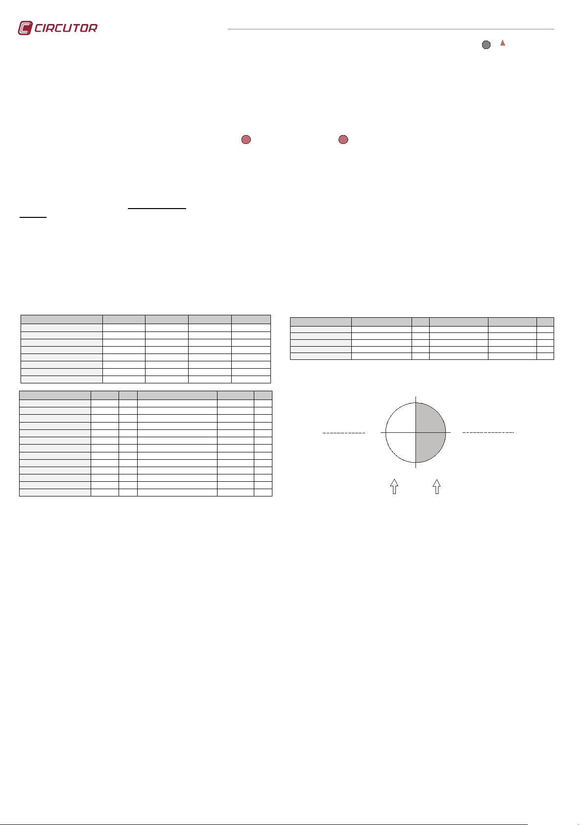
0º
90º
180º
-90º
Consumed
Power
Generated
Power
Single Phase
KW +
Kvar +
P.F +
Single Phase
KW +
Kvar C -
P.F -
Single Phase
KW Kvar P.F -
Single Phase
KW KvarL+
P.F +
Three Phase
KW III +
KVA III +
KvarL III +
Three Phase
KW III +
KVA III +
KvarC III +
Three Phase
KW III KVA III KvarC III-
Three Phase
KW III KVA III -
KvarL III -
Capacitiv e
Inductive
Inductive
Capacitiv e
4.9.- Setting the “backlight” disconnection
CVM-MINI-Ethernet
time
("diSP oFF”): Setting the time in seconds, after which
the light on the CVM-MINI -Ethernet display switches
off (low consumption) after a key is pressed. If
00 is set,
the backlight is permanently on.
4.10.- Returning the energy counters to zero
"CLr EnEr" “YES” or “no” (Clear energy counters) appears
on the display.
4.11.- Setting THD or d
Two types of Harmonic distortion can be set ("SET HAr
"):
d
-
d %: value harmonic distortion with respect to the
fundamental.
-
Thd %: value harmonic distortion with reference to
the effective value (RMS).
4.12.- Additional screen with transistor alarm outputs
(“Out 1 CodE
Out 2 CodE”) With these outputs the
CVM-MINI-Ethernet transistor output is set for:
I.Impulse every n kW.h or kvar.h (Energy): The
value in kW.h is set corresponding to one impulse
(100 msec long.): kW.h / 1 impulse or kvar.h / 1
7. - LIST OF VARIABLES AND ALARMS CODES FOR THE
Ethernet
If no variable is required enter No. par.= 00.
impulse. Maximum 5 imp/sec. (see variable
codes).
II.ALARM conditions: each output is set per
transistor the variable to be controlled, the
maximum value, minimum value and the (delay)
(see variable codes).
Note: The list of variable appears in the table below.
5.- CVM-MINI-Ethernet Blocking SET UP
This menu allows to block the setup parameter to avoid
changes. To access to this menu:
Press the
key and pressing the
key
for five seconds until Set-Up is entered.
Briefly appear on the display “set up init” and afther
“Set up” with the option::
Unlo Allows configuration of the device parameters
using the keypad.
Loc Bloquea la configuración de los parámetros del
equipo mediante el teclado.
If the Loc, option is selected, it is only possible to see the setting on entering SETUP and the changes are not allowed.
CVM-MINI -
There are also some variables that refer to the three-phases at the same time. If one
of these variables has been selected, the alarm will go off when any of the threephases meet the preset conditions.
To select this options press
NOTE: to disable the unlock mode enter the password
1234 when asked.
If a previously set option is to be changed, then it is
necessary to enter a password. PASSWORD CVM-
MINI -Ethernet
1234.
6.- CVM-MINI-Ethernet COMMUNICATIONS
One or more analysers CVM-MINI-Ethernet can be
connected to a "router" or "switch" Ethernet and access
their information through a PC connected to the same
Ethernet local area network. This system allows
centralizing data on a single registration point (Studio ®
Power System).
To change the communication settings see section 2.
The network analyzer type CVM-MINI-ETHERNET
communicates using MODBUS TCP © (Pulling
Question / Answer).
*Variables only valid if the Maximum Demand for current has been set per phase.
8. - FOUR QUADRANTS OF THE
CVM-MINI -Ethernet
M98240101-03-18A
Page 3

Power supply circuit:
- Humidity (without condensation):
AC. version
5% ….. 95%
Plus version: AC. & DC.
5% ….. 95%
Measurement circuit:
- Power consumption current circuit: ITF / Shunt
Mechanical features:
Output transistors features
Ethernet connexion
Standard IEEE802-3u
Accuracy class:
- Tª measurement: Without / with forced ventilation
+ 14.0 ºC / + 3.5 ºC
Safety:
4 wire / 3 wire (low voltage)
Detail of MC3 connection
Detail of MC1 connection - 4 wire / 3 wire
S2
P2
S1
P1
L1
L2
L3
N
S2
P2
S1
P1
S2
P2
S1
P1
N
Al
imentac
ion
Powe
r Supply
S2
P2
S1
P1
L1
L2
L3
N
S2
P2
S1
P1
S2
P2
S1
P1
N
Alimentacion
Power Supply
In case of using transformes type MC1, the selected relation
9.- TECHNICAL FEATURES
CVM-MINI-Ethernet
- Single-phase:
- Voltage tolerance:
- Frequency:
- Maximum consumption:
- Operating temperature:
- Casing material:
- Protection:
Assembled equipment (front):
Non assembled equipment (sides and rear cover):
- Dimensions (mm):
- Weight:
- Voltage measure and supply wires:
- Secondary current transformers wires:
- Maximum altitude:
- Voltage:
- Current :
- Power / Energy:
Measurement loggers: Current / Voltage
Power factor:
Scale range measurement margin: ITF / Shunt
Temperature sensor: Accuracy / Operating window
10.- CONNECTIONS
230 V AC.
-15 % / +10 %
50 - 60 Hz
3,0 VA
-10ºC …..+ 50ºC
85..265 V AC./ 95..300V DC.
50 - 60 Hz (AC. mode)
3,0 VA
-10ºC …..+ 50 º C
Self extinguishing V0 plastic
IP 51
IP 31
85 x 52 x 70 mm (3 step)
0.210 kg
Minimum section 1 mm²
Minimum section 2,5 mm²
2.000 m.
0.5 % ± 1 digit
0.5 % ± 1 digit
0.5 % ± 1 digit
External transformers / direct voltage
0.5 to 1
0.2 % ..... 120 % / 2 % ..... 120 %
± 2ºC / -10ºC ….. +50ºC
- Rated voltage: phase-neutral / between phases
- Frequency:
- Rated current:
- Permanent overload:
- Power consumption voltage circuit:
- Type: Opto-islolated transistor (open collector).
- Maximum operating voltage:
- Maximum operating current:
- Maximum frequency:
- Impulse length:
Internal WEB for Ethernet setup.
IP address assignment by DHCP or name
Password access protection
RJ45 connection
Left LED Connector Indicator. Link Status:
Right LED Connector Indicator 10M/100M:
300 V AC. / 520 V AC.
45 ~ 65 Hz
ITF In / 5A-1A
1.2 In
0.7 VA
0.18 VA
NPN
24 V DC.
50 mA
5 impulses / second
100 ms
Greem FULLDUPLEX
Ambar HALFDUPLEX
Green 100
Ambar 10
Mb/s
Mb/s
Category III - 300 V AC. / 520 AC. EN-61010 Class II double insulation against
electric shock
Standards:
IEC 664, VDE 0110, UL 94, IEC 801, IEC 348, IEC 571-1, EN 61000-6-3,
EN 61000-6-1, EN 61010-1, EN 61000-4-11, EN 61000-4-2, EN 61000-4-3,
EN 61000-4-4, EN 61000-4-5, EN 55011
11.- TECHNICAL SERVICE
In the event of any equipment failure or any operational queries please contact the technical service of CIRCUTOR.
CIRCUTOR, S.A. - Technical Assistance Service (S.A.T)
Vial Sant Jordi, s/n
08232 -Viladecavalls (Barcelona)
Tel.: (+34)93 745 29 19
E-mail : sat@circutor.com
Fax - 93 745 29 14
M98240101-03-18A
must be the same in the three transforming and must be agree
with the programmed in the CVM-MINI-MCEthernet-C2
 Loading...