

Page 1

POWER ANALYZER
CVM-MINI SERIES
INSTRUCTION MANUAL
M98174001-01-05A
CIRCUTOR, SA
Page 2

CONTENTS
1 BASIC INSTRUCTIONS............................................................................................................. 3
1.1 Checks on receipt. ....................................................................................................... 3
1.2 Main features ............................................................................................................... 3
1.3 Electrical parameters ................................................................................................... 3
1.4 Other features .............................................................................................................. 4
1.5 Available models .......................................................................................................... 4
2 INSTALLATION AND START-UP .............................................................................................. 5
2.1 Installation .................................................................................................................... 5
2.1.1 Power supply voltage............................................................................................... 5
2.1.2 Maximum voltage in the voltage measurement circuit ............................................ 5
2.1.3 Maximum permanent current in the current circuit .................................................. 5
2.1.4 Transistor output features........................................................................................ 5
2.1.5 Temperature probe features .................................................................................... 5
2.1.6 Operating conditions................................................................................................ 6
2.1.7 Safety....................................................................................................................... 6
2.2 Start-up ........................................................................................................................ 6
2.2.1 Description of terminals ........................................................................................... 6
2.2.2 Connection diagrams............................................................................................... 7
3 OPERATING MODE .................................................................................................................. 7
3.1 Keypad ......................................................................................................................... 8
3.2 Default settings ............................................................................................................ 8
3.2.1 Default display ......................................................................................................... 9
3.2.2 LED Indicators ....................................................................................................... 10
4 SETTING SET-UP.................................................................................................................... 10
4.1 Measurement Set-up ................................................................................................. 10
4.1.1 Transformation Ratios ........................................................................................... 11
4.1.1.1 Voltage primary value ................................................................................... 11
4.1.1.2 Voltage secondary value............................................................................... 11
4.1.1.3 Current primary value ................................................................................... 11
4.1.1.4 Current secondary value ............................................................................... 12
4.1.2 Measurement in 2 or 4 quadrants.......................................................................... 12
4.1.3 Power demand meter parameterisation ................................................................ 13
4.1.3.1 Integrated parameter .................................................................................... 13
4.1.3.2 Integration period .......................................................................................... 13
4.1.3.3 Clearing power demand meter value ............................................................ 14
4.1.4 Display and backlight............................................................................................. 14
4.1.4.1 Selection of screens to be displayed ............................................................ 14
4.1.4.2 Selection of start page .................................................................................. 14
4.1.4.3 Backlight (Backlit display) ............................................................................. 15
4.1.5 Clearing energy meter values................................................................................ 15
4.1.6 Setting THd or d..................................................................................................... 15
4.1.7 Digital output for the transistor (2) ......................................................................... 15
4.1.7.1 Impulse per n KW·h or Kvar·h consumed or generated ............................... 16
4.1.7.2 Alarm condition ............................................................................................. 16
4.2 Communication Set-up .............................................................................................. 19
4.2.1 Default settings ...................................................................................................... 19
4.2.2 Peripheral number ................................................................................................. 20
4.2.3 Transmission speed............................................................................................... 20
4.2.4 Parity...................................................................................................................... 20
4.2.5 Data bits................................................................................................................. 21
4.2.6 Protection of data Set-up using password............................................................. 21
5 APPENDIX – CVM-MINI-ITF-HAR-RS485-C2 SERIES .......................................................... 22
6 MODBUS RTU PROTOCOL .................................................................................................... 22
6.1 MODBUS memory map ............................................................................................. 23
6.2 RS485 Connection diagram ....................................................................................... 26
7 TECHNICAL SERVICE ............................................................................................................ 26
Page 2 of 26
Page 3

1 BASIC INSTRUCTIONS
This manual is designed to familiarise the user with operating the CVM-MINI power
analyzer in order to get the best from its features.
1.1 Checks on receipt.
Please check the following points on receipt of the analyzer:
• The equipment delivered matches your order specifications.
• Check that the equipment has not been damaged during delivery.
• Check that it has the correct instruction manual.
This manual contains information and warnings about the CVM-MINI
analyzer which must be followed to guarantee the proper operation of all
instrument functions and to maintain it in a safe condition.
Installing and maintenance for this analyzer must be carried out by a
qualified person.
1.2 Main features
The CVM-MINI panel analyzer is a programmable measuring instrument; it offers a
series of options for using it, which may be selected from configuration menus on the
instrument itself. Before starting the analyzer carefully read sections: power supply,
connection and setting and select the most suitable form of operation in order to obtain
the required data.
The CVM-MINI measures, calculates and displays the main electrical
parameters for three-phase, balanced or unbalanced industrial
systems.
Measurements are taken in true effective value using the three
alternating and neutral voltage inputs and three current inputs to
measure I
transformers.
/1A or IN /5A secondaries from external measurement
N
Figure 1. [CVM-MINI]
The CVM-MINI allows the display of all electrical parameters, using the backlit LCD
display, showing three instant electrical parameters, maximum or minimum on each
page jump.
1.3 Electrical parameters
By using its internal processor, the CVM-MINI shows on the screen and through
communication (according to model), over 100 parameters, which may be either singlephase or three-phase. These parameters may or may not be displayed on the screen,
according to the equipment’s preset values.
Page 3 of 26
Page 4

PARAMETER UNIT L1 L2 L3 III
Phase-neutral voltage V f-n • • •
Phase-phase voltage V f-f • • •
Current A • • • ••
Frequency Hz •
Active power kW • • • •
Reactive power L kvarL • • • •
Reactive power C kvarC • • • •
Apparent power kVA • • • •
Power factor PF • • • •
Cos ϕ Cos
ϕ
•
Maximum demand Pd • • • •
Neutral current IN •
Voltage THD % THD - V • • •
Current THD % THD - A • • •
kWh (consumption and generation) W·h •
kvarh.L (consumption and generation) W·h •
kvarh.C (consumption and generation) W·h •
kVAh (consumption and generation) W·h •
Harmonic content (V and A) * % • • • 15th
Temperature ºC •
( • ) Available through display and communications.
( •• ) Only available through communications.
( * ) Harmonic content in HAR model.
1.4 Other features
• A small sized instrument with a 85x52x70mm (3 steps).
• Measurement in true effective value (TRMS).
• Instant, maximum, minimum values for each parameter.
• Energy measurer function.
• 1 GW·h counter in consumed energy.
• 100 MW·h counter in generated energy.
• Backlit LCD display.
• Built in RS485 communications (Modbus RTU®).
• Temperature probe built in the equipment.
1.5 Available models
CODE REFERENCE
M52000 CVM-MINI-Shunt
M52010 CVM-MINI-ITF
M52021 CVM-MINI-ITF-RS485-C2
M52031 CVM-MINI-ITF-HAR-RS485-C2
M52022 CVM-MINI-ITF-Plus-RS485-C2
=cl]
onil
O?L+(**
Page 4 of 26
Page 5

2 INSTALLATION AND START-UP
This manual contains information and warnings about the analyzer which must be
followed to guarantee the proper operation of all instrument functions and to maintain it
in a safe condition. The analyzer must not be switched on until it is finally connected to
the electrical board.
If the equipment is handled in a way not specified by the manufacturer, the
When it is likely that the equipment has lost its protection (i.e. with visible damage), it
must be disconnected from the auxiliary supply. In this event, contact a qualified
technical service representative.
equipment's protection may be compromised.
2.1 Installation
The following features must be taken into consideration before supplying power to the
equipment:
2.1.1 Power supply voltage
Standard model power supply: Single-phase 230 V AC.
Plus model power supply: 85…265 V AC. / 95…300 V DC.
Frequency: 50 Hz … 60 Hz
Power supply tolerance: -15 % / +10%
Connection terminals: 14 - 15
Equipment consumption: 3 VA
2.1.2 Maximum voltage in the voltage measurement circuit
Voltage: 300 V ∼ AC. phase-neutral
520 V ∼ AC. phase-phase
Frequency: 50 Hz … 60 Hz
2.1.3 Maximum permanent current in the current circuit
In scale IN /1A: 1.2 amperes
In scale I
/5A: 6.0 amperes
N
2.1.4 Transistor output features
Type NPN transistor: Opto-insulated / Open Collector
Maximum operating voltage: 24 V DC.
Maximum operating current: 50 mA
Maximum frequency: 5 impulses / second
Impulse length: 100 ms
2.1.5 Temperature probe features
The CVM-MINI has a built in temperature sensor. The sensor has a ± 2ºC
accuracy and a temperature measurement range of -10ºC +50ºC.
The interior temperature of the CVM-MINI has been estimated at 14.0 ºC above
the interior of the cabinet where it has been installed, if the cabinet has no
ventilation. If the cabinet has forced ventilation then the temperature of the CVM
is 3.5 ºC higher.
Page 5 of 26
Page 6
2.1.6 Operating conditions
Operating temperature: -10 ºC / +50ºC
Relative humidity: 5 to 95 % RH (without condensation)
Altitude: Up to 2000 metres
2.1.7 Safety
Designed for category III installations, 300 V ∼ AC (EN 61010).
Class II double insulation against electric shock protection.
2.2 Start-up
The equipment is mounted on a DIN rail 46277 (EN 50022). All connections must
remain inside the electrical board.
Note that when the instrument is switched on, the terminals may be dangerous
when touched and opening or removing parts may access dangerous areas.
Therefore, the equipment must not be used until it is properly installed.
The equipment must be connected to a power supply circuit protected with gl (IEC 269)
or type M fuses between 0.5 and 2 A. It must have an overload/short circuit switch or
equivalent device in order to disconnect the equipment from the power supply system.
An earth leakage switch or similar device must be fitted to disconnect the equipment
from the power supply system. The power supply circuit and the voltage measurement
circuit are connected with a cable with a minimum diameter of 1 mm
The secondary line for the current transformer shall have a minimum diameter of 2.5
2
.
mm
2
.
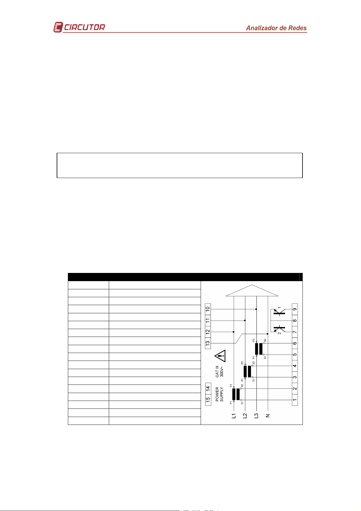
2.2.1 Description of terminals
TERMINAL TERMINAL DESCRIPTION
1 Current input AL1 - S1
2 Current input AL1 - S2
3 Current input AL2 - S1
4 Current input AL2 - S2
5 Current input AL3 - S1
6 Current input AL3 - S2
7 Transistor output RL2
8 Common transistor output
9 Transistor output RL1
10 Measurement VL3
11 Measurement VL2
12 Measurement VL1
13 Neutral V measurement
14 Power supply voltage input
15 Power supply voltage input
A RS-485 (+)
S RS-485 (GND)
B RS-485 (-)
Page 6 of 26
Page 7
S2
P2
S1
P1
S2
P2
S1
P1
S2
P2
P1
Ali
m
e
n
tac
ionPower Supply
S2P2S1
P1
S2P2S1
P1
S2
P2S1P1
b
B
a
A
b
BaA
b
B
a
AbBaA
S2
P2
S1
P1
S2P2S1
P1
Alim
e
n
tacionP
o
w
e
r Suppl
y
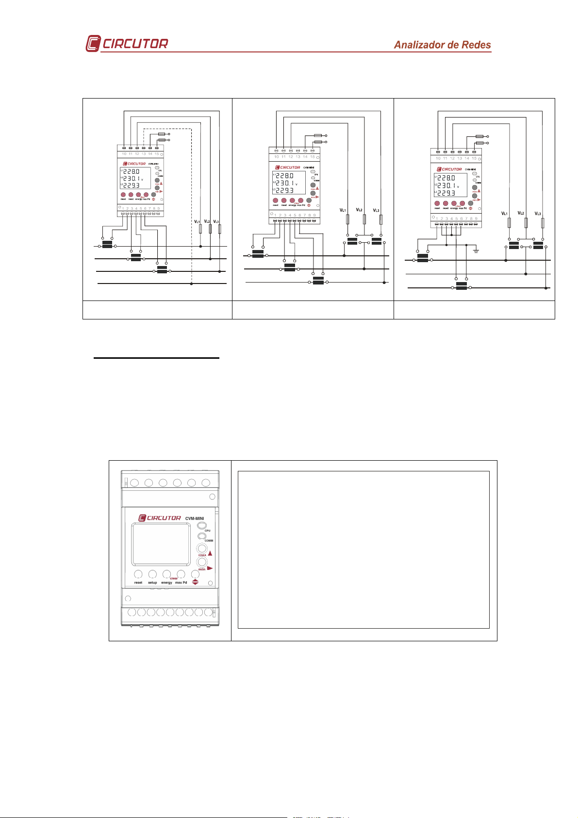
2.2.2 Connection diagrams
N
S1
L1
L2
L3
N
Figure 2. [4-wire / 3-wire - Low Voltage] Figure 3. [2 voltage transformers -
L1
L2
L3
3 current transformers]
L1
L2
L3
Figure 4. [2 voltage transformers -
2 current transformers]
3 OPERATING MODE
When power is supplied to the CVM-MINI, the equipment will start its software interface
on the screen showing the version of the firmware and its setting. After a few seconds
the equipment is ready to operate and shows all available screens.
Once started the power analyzer will display the programmable electrical parameters
via the measurement Set-up. If there is no previous setting, the analyzer will display the
voltage between phase and neutral for L1, L12 and L1
THD
PF
Pd
C
I
OS
Hz
N
=cl]
onil
L1
'
2(2(2(2
L2
O?L+(**
'
2(2(2(2
kvVAr=h
L3
'
Figure 5. CVM-MINI
2(2(2(2(22
Figure 6. CVM-MINI display - LCD SEGMENTS
Page 7 of 26
Page 8
clear
clear
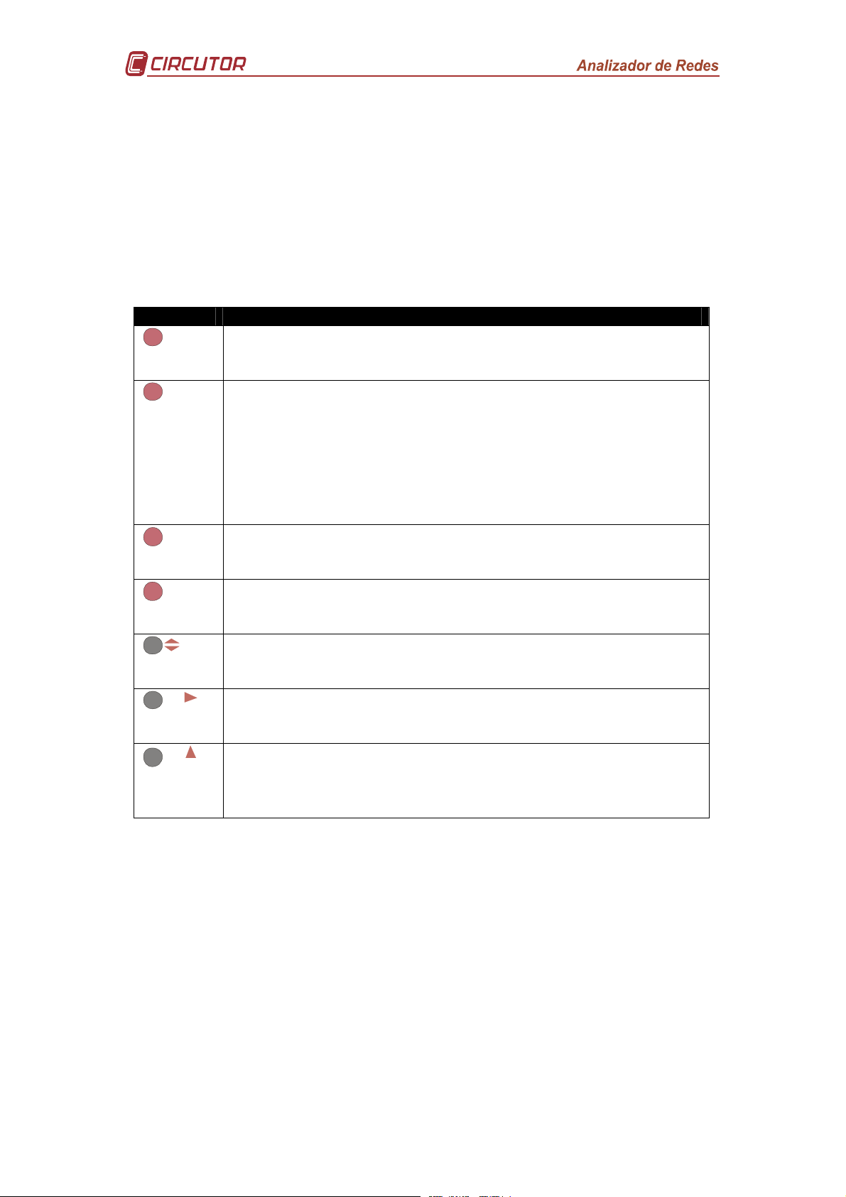
3.1 Keypad
The keypad comprises a total of seven silicon buttons which are used to set the
equipment. Some buttons have a rapid access function, i.e. entering the Set Up
interface is not required. Only the rapid access key needs to be pressed to run the
function.
Only three of the seven buttons may be pressed when the upper cover is down. This is
because the remaining five keys have a high risk factor if they were to be accidentally
pressed.
KEY FUNCTION
resetN
Nsetup
energy
max Pd
min
max
Starting the equipment and clearing maximum and minimum values
for all instant parameters. Pressing the Reset key is equivalent to
starting the equipment in the absence of voltage.
Using a long press, after starting the equipment (in the absence of
voltage, or after pressing the Reset key), Communication Set-up is
accessed. Here the RS485 port parameters may be set and all
communication and measurement parameters may be blocked
using a password.
Using a long press, after starting the equipment (runtime mode),
Measurement Set-up is accessed. Each and every parameter for
measurement may be changed.
Rapid access function; using a long press (pressed for 5 seconds),
all enabled energy counters are cleared (kW·h / kvarL·h / kvarC·h /
kVA·h in power consumption or consumption and generation).
Rapid access function; using a long press (pressed for 5 seconds),
the Power demand parameter previously set in Measurement Set-
up is cleared (Power demand) (kW III / kV·A III / A III / A ph).
Displaying all electrical variables by repeated presses, in runtime
mode. In Set-up mode has the function of advancing the setting
screens.
Pressing in runtime mode, displays the minimum value of displayed
variable/s. In Set-up mode it has the function of moving 1 digit
sideways.
Pressing in runtime mode, maximum variable values are displayed.
In Set-up mode it has the function of increasing 1 digit cyclically
(from * to 3), or selecting between two possible preset
configurations (for example: s_m or hi).
3.2 Default settings
The CVM-MINI Analyzer has a factory setting for display, communication and
measurement. For this reason and due to the fact that this default setting is not valid in
nearly all cases, the user must properly set-up the display, measurement and
communication in accordance with the installation’s requirements.
Page 8 of 26
Page 9

*(33*(33*(3
3
PdPF
{-23(/
{-3*(+
,,3(2
{,-*(+
L2 L3
3.2.1 Default display
L1
{,,3(/
V
Figure 7. Phase-neutral voltage
L1
{{{1(0
L2
{{+.(+
L3
K VAr
{{{1(0
Figure 11. Reactive power per
L1
phase
THD
{{{0&.
L2
{{{/(*
L3
A
{{{.&3
Figure 15. % harmonic
distortion in current per phase
{{*(33
{-13&.
Figure 19. Cos ϕϕϕϕ III / Apparent
power III
C
K VA
L1
{/*-&,
L2
{/1*(3
L3
{//*(2
Figure 9. Current per phase
L1
Figure 8. Phase-phase voltage
L1
V
{++1(3
L2
{+--(.
L3
K VA
L2
L3
{+,2(/
Figure 12. Apparent power per
{{*(33
{-11(3
Figure 16. PF III / Active power
OS
{{30&,
phase
III
PF
kvV
I
N
Hz
{{/*(*
{{,.&0i=
Figure 20. Neutral current /
Frequency / Temperature
Figure 13. Power factor per
{{*(33
{{,3(,
Figure 17. PF III / Inductive
{-1/&/
Figure 21. Maximum demand
phase
PF
K VArF
reactive power III
Pd
kvV
L1
{++1&,
A
L2
{+-,&/
L3
{+,2&/
Figure 10. Active power per
L1
{{{+(-
L2
{{{+(-
L3
{{{+(*
Figure 14. % harmonic
distortion in voltage per phase
{{*(33
{{{{*
Figure 18. PF III / Capacitive
/,-.3(+
Figure 22. Imported / Consumed
kvV
phase
THD
V
PF
K VAr=
reactive power III
kvV h
active energy
K VArFh
{+,.0(.
Figure 23. Imported / Consumed
inductive reactive energy
K VArFh
'+,.0(.
Figure 27. Exported / Generated
inductive reactive energy
{{,/-(,
Figure 24. Imported / Consumed
capacitive reactive energy
'{,/-(,
Figure 28. Exported / Generated
capacitive reactive energy
Page 9 of 26
K VAr=h
K VAr=h
/,002(0
Figure 25. Imported / Consumed
apparent energy
',002(0
Figure 29. Exported / Generated
apparent energy
K VA h
K VA h
,-.3(+-
Figure 26. Exported / Generated
active energy
kvV h
Page 10

3.2.2 LED Indicators
The CVM-MINI power analyzer is supplied with two LED indicators which give
information on the status of:
LED FUNCTION
CPU
The slow flashing of the LED CPU shows that the equipment has
auxiliary power supply and is operative.
The rapid flashing of the LED CPU shows that there is an internal
problem with the start up software.
COMM
The slow flashing of the COMM LED shows that the equipment is
communicating with a master peripheral via its RS485
communications port. The CVM-MINI
power analyzer’s
communications protocol is Modbus RTU.
4 SETTING SET-UP
The CVM-MINI power analyzer has two very different Set-up configurations which can
set the parameters for all the measurement and communication settings.
Measurement set-up: All parameterisation of the equipment’s measurements are
carried out from this menu; voltage display (phase-neutral or phase-phase voltages
and current transformer ratios, setting the power demand meter, setting the start page,
backlight setting, returning the energy counters to zero and maximum demand, type of
harmonic distortion and setting the transistor outputs.
Communication set-up: All of the analyzer’s RS485 RTU Modbus communications are
parameterised from this set-up menu. Also the option to enter a password to protect
previous data settings in both Set-ups is possible from this menu.
4.1 Measurement Set-up
The measurement parameters for the CVM-MINI and all its functions are changed from
this menu (according to type); it may start the eight energy meters and reset maximum
demand (Pd), maximums and minimums recorded.
The analyzer does not store the setting changes until all of the setting has been
finished; the analyzer does not store the changes to the settings until the whole setting
program has been completed. If
setting entered is not stored in the memory.
To access MEASUREMENT Set-Up the SETUP key has to be pressed with a
long press with the equipment started until setting mode is entered.
On entering setting mode, the message "M?NOJ{ fi]", or as a default "M?NOJ{
ohfi" is displayed for a few seconds indicating that it is in setting and is informing of
their status (locked or unlocked respectively).
M?NOJ{ohfi: on entering setting mode it is possible to view and change the setting.
M?NOJ{fi]: on entering setting mode it is possible to view the parameterisation but
it is not possible to change it.
resetN
is pressed before the end of the setting, the
Page 10 of 26
Page 11
4.1.1 Transformation Ratios
This menu accesses the voltage and current ratios and the voltage and current
primary and secondary may be changed.
4.1.1.1 Voltage primary value
The display shows ”m_n{JlcO” followed by six digits; these allow the setting
of the transformer voltage primary.
To write or change the voltage transformer primary value, repeatedly press the
ma x
key increasing the value of the digit which is flashing at the time.
When the required value is on the screen, move on to the following digit by
pressing
When the last digit has been changed, press
digit, allowing the previously set values to be changed again. To enter the data
and access the next setting process, press .
min
, to change the remaining values.
min
to move back to the first
m_n
JlcO
*****+
Figure 30. Voltage primary ratio
4.1.1.2 Voltage secondary value
The display shows ”m_n{ M_]O” followed by three digits; these allow the
setting of the transformer voltage secondary.
To write or change the voltage transformer secondary value, repeatedly press
ma x
the
When the required value is on the screen, move on to the following digit by
pressing
When the last digit has been changed, press
digit, allowing the previously set values to be changed again. To enter the data
and access the next setting step, press
key increasing the value of the digit which is flashing at the time.
min
, to change the remaining values.
.
min
to move back to the first
m_n
M_]O
{{{**+
Figure 31. Secondary voltage ratio
4.1.1.3 Current primary value
The display shows ”m_n{JlC;” followed by five digits; these allow the setting
of the transformer current primary.
To write or change the current primary value, repeatedly press the
increasing the value of the digit which is flashing at the time.
When the required value is on the screen, move on to the following digit by
pressing
min
, to change the remaining values.
Page 11 of 26
ma x
key
Page 12

90º
Capacitive
When the last digit has been changed, press
digit, allowing the previously set values to be changed again. To enter the data
and access the next setting step, press
min
to move back to the first
.
m_n
jlc[
{****/
Figure 32. Current primary ratio
4.1.1.4 Current secondary value
Due to the fact that the CVM-MINI analyzer has a double scale for measuring
the current secondary, the secondary to be measured by the analyzer must be
set (I
To select one of the two display measurement options, press the
the two options will alternate. Once the required secondary of current has been
selected, press the
/1A or IN /5A).
N
key to enter the data and access the next setting step.
m_n
M_][
{{{/
Figure 33. Current secondary value IN /5A Figure 34. Current secondary value IN /1A
m_n
M_][
{{{+
ma x
key and
4.1.2 Measurement in 2 or 4 quadrants
The CVM-MINI power analyzer may measure in two quadrants (power
consumption), or in four quadrants (power consumption and generation). If
measurements are only to be taken in power consumption, the two quadrant
option is recommended to avoid exported or generated energies being displayed
(-kW·h / -kvarL·h / -kvarC·h / -kVA·h).
Capacitive
Inductive
180º
Inductive
0º
-90º
Page 12 of 26
Page 13

To select one of the two display options (2 or 4 measurement quadrants), press
ma x
the
selected, press the
key and the two options will alternate. Once the required option is
key to enter the data and access the next setting step.
m_n
ko[^
{{{.
Figure 35. Measurement in 4 quadrants Figure 36. Measurement in 2 quadrants
m_n
ko[^
{{{,
4.1.3 Power demand meter parameterisation
The
CVM-MINI
instant parameter. The amplitude of this window is preset by the integration time.
4.1.3.1 Integrated parameter
The display shows ”
or variable to be integrated as Maximum Demand.
To select one of the four integration parameters available, press the
and the four options will alternate in turn. Once the required option is selected,
press the key to enter the data and access the next setting step.
power demand meter is the integration in the time of a preset
J^{=i^_
” followed by two digits which identify the code
ma x
key
J^
=i^_
{{+0
Figure 37. Active power III
If “
J^{ =i^_{ **
meter will be deactivated.
4.1.3.2 Integration period
The Integration Period of the power demand meter may vary between a
minimum of 1 minute up to a maximum of 60 minutes.
To write or change the integration time value, repeatedly press the
increasing the value of the digit which is flashing at the time.
When the required value is on the screen, move on to the following digit by
pressing
When the last digit has been changed, press
digit, allowing the previously set values to be changed again. To enter the data
and access the next setting step, press
min
J^
=i^_
{{-.
Figure 38. Apparent power III
” is selected, the instant integration of the power demand
, to allow the remaining values to be changed.
J^
=i^_
{{-0
Figure 39. Current III
min
.
J^
=i^_
['jb
Figure 40. Current per phase
to move back to the first
ma x
key
Page 13 of 26
Page 14

4.1.3.3 Clearing power demand meter value
To clear or save maximum demand, press the
alternate. Once the required option is selected, press the
data and access the next setting step.
ma x
key and the two options will
key to enter the
=fl
j^
hi
Figure 41. No-clearing power demand meter value Figure 42. Clearing power demand meter value
=fl
j^
s_m
4.1.4 Display and backlight
4.1.4.1 Selection of screens to be displayed
Due to the fact that the
default screens (as shown in section 3.2.1 Default display), the user has the
option of setting a personalised display by selecting screens to be displayed.
The display shows as default “
pressed to proceed to the personalised display option. The analyzer will show
^_`{j[a_{hi
“
press
Once the personalisation option has been entered, by using
screens shown in section 3.2.1 Default display will be displayed in turn. By
using the
hi
” respectively.
“
.
ma x
” on the screen; to enter the data and proceed to this setting,
button, the screen to be displayed is selected. Select “
CVM-MINI
power analyzer has a large number of
^_`{ j[a_{ s_m
”; the
ma x
key has to be
key the
s_m
” or
4.1.4.2 Selection of start page
In order to select the equipment’s preferred start up screen, repeatedly press
ma x
the
is selected, press the
step.
key up to display the screen to be selected. Once the required option
key to enter the data and access the next setting
L1
{m_n
L2
{chcn
L3
{j[a_
Figure 43. Select preferred page
Rotating function: Using the rotating display function, the Power analyzer
automatically displays every available screen for five seconds each.
The
parameters are flashing at the same time.
must be used to enter the rotating display function when all electrical
V
Page 14 of 26
Page 15

4.1.4.3 Backlight (Backlit display)
The time in which the back lighting will be on after the last use is set by using
the keypad in this menu. The display is permanently on if
**
is set.
4.1.5 Clearing energy meter values
Clearing energy meters refers to the four consumed or imported energy meters.
To select clear these meters of
alternate. Once the required option is selected, press the
data and access the next setting step.
kw·h
, press the
ma x
key and the two options will
key to enter the
{]fl
{_h_l
{hi
Figure 44. No-clearing energy meters Figure 45. Clearing energy meters
{]fl
{_h_l
{s_m
4.1.6 Setting THd or d
Harmonic distortion rate
options: the effective value or the fundamental value.
To select one of the two calculation options, press the
options will alternate. Once the required option is selected, press the
enter the data and access the next setting step.
{m_n
{B;L
{NB>
Figure 46. Harmonic distortion value for the
effective value (RMS)
measurements may be made using two measurement
ma x
key and the two
{m_n
{B;L
{>
Figure 47. Harmonic distortion value for the
fundamental value
key to
4.1.7 Digital output for the transistor (2)
Two types of setting may be made using the
outputs:
•
Impulse per n
or generated may be set to generate an impulse.
•
Alarm condition: associates a parameter to a digital output, setting a
maximum, minimum and delay (
In the event that no condition needs to be set, the
using the
key.
kW·h
or
kvar·h
Page 15 of 26
(Energy): the value for the energy consumed
delay
) for the trip condition.
CVM-MINI’s
**
code is typed and entered
digital transistor
Page 16

4.1.7.1 Impulse per n KW·h or Kvar·h consumed or generated
In order to generate an impulse for consumed
used has to be selected:
PARAMETER SYMBOL CODE
Active energy III
Inductive reactive energy III
Capacitive reactive energy III
Apparent energy III
Active energy generated III
Inductive reactive energy generated III
Capacitive reactive energy generated III
Apparent energy generated III
Once the energy code has been selected and entered using the key, the
watts·time per impulse is entered or as a default, kilowatts·time per impulse.
For entering the watts·time rate per impulse, repeatedly press the
increasing the value of the digit which is flashing at the time.
When the required value is on the screen, move on to the following digit by
pressing
When the last digit has been changed, press
digit, allowing the previously set values to be changed again. To enter the data
and access the next setting step, press
min
, to allow the remaining values to be changed.
.
n kW·h
, the energy meter to be
kW·h III
KvarL·h III
KvarC·h III
kVA·h III
kW·h III (-)
KvarL·h III (-)
KvarC·h III (-)
kVA·h III (-)
min
to move back to the first
31
32
33
44
45
46
47
48
ma x
key
{Ion+
{Jofm
{***(***
Figure 48. Watts / impulse
4.1.7.2 Alarm condition
In order to link an alarm condition to an energy parameter, the code for the
selected parameter has to be entered. A list of electrical parameters and their
codes is shown below.
Page 16 of 26
Page 17

PARAMETER PHASE SYMBOL CODE
Phase-neutral voltage L1
Current L1
Active power L1
Reactive power L/C L1
Apparent power L1
Power factor L1
% THD V L1
% THD A L1
Phase-neutral voltage L2
Current L2
Active power L2
Reactive power L/C L2
Apparent power L2
Power factor L2
% THD V L2
% THD A L2
Phase-neutral voltage L3
Current L3
Active power L3
Reactive power L/C L3
Apparent power L3
Power factor L3
% THD V L3
% THD A L3
Temperature -
V 1
A 1
kW 1
KvarL/C 1
kV·A
PF 1
THD V1
THD A1
V 2
A 2
kW 2
KvarL/C 2
kV·A
PF 2
THD V2
THD A2
V 3
A 3
kW 3
KvarL/C 3
kV·A
PF 3
THD V3
THD A3
ºC
01
02
03
04
38
05
25
28
06
07
08
09
39
10
26
29
11
12
13
14
40
15
27
30
41
PARAMETER SYMBOL CODE PARAMETER SYMBOL CODE
Active power III
Inductive power III
Capacitive power III
Active energy
Inductive reactive energy
Capacit. reactive energy
Apparent power III
Maximum demand
Current III
Neutral current
* Variables only valid if the Maximum Demand for current has been set per phase.
There are also some codes which refer to the three-phases at the same time
(Function OR). If one of these variables has been selected, the alarm will go off
when any of the three-phases, or all three at the same time, match the preset
conditions.
kW III
kvarL III
kvarC III
kW·h
Kvarh·L
Kvarh·C
kV·A III
Md (Pd)
AIII
IN
16
17 Power factor III
18 Frequency
31 L1- L2 Voltage
32 L2- L3 Voltage
33 L3- L1 Voltage
34 Temperature
35 Maximum demand L1
36 Maximum demand L2
37 Maximum demand L3
cos
ϕ
three-phase
cos ϕ
PF III
Hz
V 12
V 23
V 31
ºC
Md (Pd)
Md (Pd)
Md (Pd)
19
20
21
22
23
24
41
35*
42*
43*
Page 17 of 26
Page 18

PARAMETER SYMBOL CODE
Phase-neutral voltage
Current
Active power
Reactive power
Apparent power
Power factor
Phase-phase voltage
% THD V
% THD I
Once the Alarm Condition code has been selected and the data entered using
the
(hysteresis) for the alarm condition must be entered.
For entering the maximum, minimum and hysteresis values, repeatedly press
the
When the required value is on the screen, move on to the following digit by
pressing
When the last digit has been changed, press
digit, allowing the previously set values to be changed again. In order to enter
one of the pieces of data, press the
press the
key, the
ma x
key increasing the value of the digit which is flashing at the time.
min
maximum value, minimum value
, to allow the remaining values to be changed.
key entering the data and ending the setting.
V1 / V2 / V3
A1 / A2 / A3
kW1 / kW2 / kW3
Kvar1 / kvar2 / kvar3
kV·A1 / kV·A2 / kV·A3
PF1 / PF2 / PF3
V12 / V23 / V31
Thd1 / Thd2 / Thd3 V
Thd1 / Thd2 / Thd3 A
and the
min
to move back to the first
key. Once the delay has been set,
delay
90
91
92
93
98
94
95
96
97
in seconds
{Ion+
{BC
{***(*
Figure 49. Maximum value
Setting the number 2 digital output is shown on the display as “
must be set by using the settings shown below.
MIN +
MIN +
MIN -- MAX +
MIN + MAX --
MIN --
MIN --
Activating the outputs of the programmable values as Maximums and
Minimums.
MAX +
max > min
MAX +
max < min
MAX -max > min
MAX -max < min
{Ion+
{fi
{***(*
Figure 50. Minimum value
ON OFF ON
======
0 Min Max
OFF ON OFF
==============
0 Max Min
ON OFF ON
=======
Min 0 Max
OFF ON OFF
=============
Max 0 Min
ON OFF ON
=====
Min Max 0
OFF ON OFF
================
Max Min 0
{Ion+
{^_f[
{****
Figure 51. Hysteresis / Delay
Ion{,
”. This
Page 18 of 26
Page 19

4.2 Communication Set-up
One or more
to automate a production process or an energy control system. As well as the usual
operation of each instrument, this system may centralize data at one single point; for
this reason the
If more than one instrument is connected to one single series line (RS-485), it is
necessary to assign to each a number or address (from 01 to 255) so that the central
computer or PLC sends the appropriate requests to these addresses for each
peripheral.
From communication
displayed and/or changed; this may match these parameters to the requirements of the
system topologies and/or applications.
The analyzer does not store the setting changes until all of the setting has been
finished. If it is
the memory.
To access the COMMUNICATION Set-up, first press the
On entering setting mode the message "
informing the user that the equipment has entered communications display or setting
mode.
CVM-MINI
CVM-MINI
Reset
immediately press the
instruments may be connected to a computer or PLC in order
has an RS-485 communication output.
Set-up
before the end of the setting, the setting entered is not stored in
, the
Set-up
CVM-MINI
key for a long time to enter a setting.
's communication parameters may be
Reset
M?NOJ{chc]
" appears for a few seconds,
key and
{m_n
{jlin
{\om
Figure 52. Protocol information
Using this information screen, the equipment is informing the user that the
Communication protocol via the RS-385 series port is standard MODBUS©.
To enter setting mode, press the
4.2.1 Default settings
This menu option allows the automatic selection of a predefined communication
parameter; the default preset parameters are: Peripheral number 1, speed 9,600
bps, parity NO, data bits 8 and stop bit 1.
If a different preset communication setting is not required, “
selected.
To select one of the two options, just press the
alternate. Once the required option is selected, press the
data and access the next setting step.
key.
hi
” should be
ma x
key and the two options will
key to enter the
Page 19 of 26
Page 20

{m_n
{=^_`
{hi
Figure 53. Non-standard communication
parameters
{m_n
{=^_`
{s_m
Figure 54. Predefined communication
parameters
4.2.2 Peripheral number
The peripheral number varies between 0 and 255 (0 and FF in hexadecimal).
To write or change the number of the peripheral, repeatedly press the
increasing the value of the digit which is flashing at the time.
When the required value is on the screen, move on to the following digit by
pressing
When the last digit has been changed, press
allowing the previously set values to be changed again. To enter the data and
access the next setting step, press
min
, to allow the remaining values to be changed.
.
min
to move back to the first digit,
ma x
key
{m_n
{hj_l
{{**+
Figure 55. Peripheral number
4.2.3 Transmission speed
The transmission speed of RS485 communication bus may be: 1,200 bps, 2,400
bps, 4,800 bps, 9,600 bps or 19,200 bps. To select one of the transmission
speeds available, press the
Once the required option is selected, press the
access the next setting step.
ma x
key and the four options will alternate in turn.
key to enter the data and
{m_n
{\[o^
{{+3,**
Figure 56. Transmission speed
4.2.4 Parity
Parity may be selected, even or odd; to select the type of parity, press the
key and the three options will alternate in turn. Once the required option is
selected, press the key to enter the data and access the next setting step.
ma x
Page 20 of 26
Page 21

{m_n
{J[lc
{hi
Figure 57. Parity
4.2.5 Data bits
7 or 8 data bits may be selected; to select the number of bits, press the
and the two options will alternate in turn. Once the required option is selected,
press the
key to enter the data and access the next setting step.
ma x
key
{m_n
{mnij
{{{{+
Figure 58. Data bits
4.2.6 Protection of data Set-up using password
This menu option aims to protect the data set in
As a default the equipment does NOT protect data with the “
pressing the
If, on the other hand, the parameters in
the option “
pressed. The protection password as a default will always be
password code entered will be incorrect.
key the data is entered and setting the equipment is finalised.
Measurement Set-up
Fi]
” has to be selected using the
Measurement Set-up
ohfi
are to be protected,
ma x
key and then the key
.
” option. By
+,-.
; any other
{m_n
{j[mm
{****
Figure 59. Password request to
protect Set-up data
For entering the password, repeatedly press the
the digit which is flashing at the time.
When the required value is on the screen, move on to the following digit by
pressing
When the last digit has been changed, press
allowing the previously set values to be changed again. In order to enter the
password, press the
key entering the data and ending the setting.
In the event that the measurement SETUP parameters are to be changed again,
the equipment has to be first unlocked by the same procedure (position “
and the appropriate changes are made.
min
, to allow the remaining values to be changed.
key. Once the password has been set, press the
{m_n
{j[mm
{+,-.
Figure 60. Enter password to protect
Set-up data
ma x
key increasing the value of
min
to move back to the first digit,
ohfi
”),
Page 21 of 26
Page 22

5 APPENDIX – CVM-MINI-ITF-HAR-RS485-C2 SERIES
The
CVM-MINI
harmonic in voltage and current, showing the content on the LCD display. Therefore,
the HAR has a high number of display screens, where the value of the current and
voltage fundamental and the content of each harmonic may be seen.
The equipment’s display diagram is obtained by using the following procedure:
Series has an analyzer for the harmonic content up to the 15th
Figure 61. Display of Harmonic Content in Voltage and Current
6 MODBUS RTU PROTOCOL
The
CVM-MINI
MODBUS protocol the RTU (Remote terminal Unit) mode is used; each 8-bit per byte
in a message contains two 4-bits hexadecimal characters.
The format for each byte in RTU mode is:
power analyzer communicates using the MODBUS© protocol. In the
Page 22 of 26
Page 23

Code 8 bit binary, hexadecimal 0-9, A-F.
2 hexadecimal characters contained in each 8-bit field in
the message.
Bits per byte 8 data bits.
Field Check-Error CRC Type (Cyclical Redundancy Check).
Modbus functions used:
Function 01 Reading the status of the relays.
Function 03 and 04 Reading n Words (16 bits-2 bytes). Function used for
reading the electrical parameters that the
measuring. All electrical parameters are long with 32 bits,
because of this two Words are required to request each
parameter.
(4 bytes - XX XX XX XX)
Function 05 Writing a relay.
CVM-MINI
is
6.1 MODBUS memory map
PARAMETER SYMBOL
Voltage phase
Current
Active power
Reactive power
Apparent power
Power factor
Voltage phase
Current
Active power
Reactive power
Apparent power
Power factor
Voltage phase
Current
Active power
Reactive power
Apparent power
Power factor
Temperature
V L1
A L1
kW L1
Kvar L1
kV·A L1
PF L1
V L2
A L2
kW L2
Kvar L2
kV·A L2
PF L2
V L3
A L3
kW L3
Kvar L3
kV·A L3
PF L3
ºC
Instant Maximum Minimum Units
00-01 60-61 C0-C1
02-03 62-63 C2-C3
04-05 64-65 C4-C5
06-07 66-67 C6-C7
4A-4B AA-AB 10A-10B
08-09 68-69 C8-C9
0A-0B 6A-6B CA-CB
0C-0D 6C-6D CC-CD
0E-0F 6E-6F CE-CF
10-11 70-71 D0-D1
4C-4D AC-AD 10C-10D
12-13 72-73 D2-D3
14-15 74-75 D4-D5
16-17 76-77 D6-D7
18-19 78-79 D8-D9
1A-1B 7A-7B DA-DB
4E-4F AE-AF 10E-10F
1C-1D 7C-7D DC-DD
50-51 B0-B1 110-111
V x10
V x10
V x10
ºC x 10
mA
w
w
x 100
mA
w
w
w
x 100
mA
W
W
w
x 100
Page 23 of 26
Page 24

PARAMETER SYMBOL
Active power III
Inductive power III
Capacitive power III
Cos φ III
Power factor III
Frequency
Voltage line L1-L2
Voltage line L2-L3
Voltage line L3-L1
% THD V L1
% THD V L2
% THD V L3
% THD A L1
% THD A L2
% THD A L3
Apparent power III
Maximum demand
Three-phase current (average)
Neutral current
Maximum demand A2
Maximum demand A3
kW III
KvarL III
KvarC III
Cos φ III
PF III
Hz
V12
V23
V31
%THD VL1
%THD VL2
%THD VL3
%THD AL1
%THD AL2
%THD AL3
KvaIII
Md (Pd)
A_AVG
In
Md (Pd)
Md (Pd)
PARAMETER SYMBOL
Active energy
Inductive reactive energy
Capacitive reactive energy
Apparent energy
Active energy generated
Inductive energy generated
Capacitive energy generated
Apparent energy generated
kW·h III
kvarL·h III
kvarC·h III
kVA·h III
kW·h III (-)
kvarL·h III (-)
kvarC·h III (-)
kVA·h III (-)
Instant Maximum Minimum Units
1E-1F 7E-7F DE-DF
20-21 80-81 E0-E1
22-23 82-83 E2-E3
24-25 84-85 E4-E5
26-27 86-87 E6-E7
28-29 88-89 E8-E9
2A-2B 8A-8B EA-EB
2C-2D 8C-8D EC-ED
2E-2F 8E-8F EE-EF
30-31 90-91 F0-F1
32-33 92-93 F2-F3
34-35 94-95 F4-F5
36-37 96-97 F6-F7
38-39 98-98 F8-F9
3A-3B 9A-9B FA-FB
42-43 A2-A3 102-103
44-45 A4-A5 104-105
46-47 A6-A7 106-107
48-49 A8-A9 108-109
52-53 B2-B3 112-113
54-55 B4-B5 114-115
MODBUS VARIABLES
Instant Maximum Minimum Units
3C-3D 9C-CD FC-FD
3E-3F 9E-9F FE-FF
40-41 A0-A1 100-101
56-57 B6-B7 116-117
58-59 B8-B9 118-119
5A-5B BA-BB 11A-11B
5C-5D BC-BD 11C-11D
5E-5F BE-BF 11E-11F
w
w
w
x 100
x 100
Hz x 10
V x10
V x10
V x10
% x 10
% x 10
% x 10
% x 10
% x 10
% x 10
w
w/VA/mA
mA
mA
mA
mA
w·h
w·h
w·h
w·h
w·h
w·h
w·h
w·h
Page 24 of 26
Page 25

* Recordings available in HAR model
MODBUS VARIABLES
PARAMETER SYMBOL L1 L2 L3 Units
Harmonic content in VOLTAGE
RMS current
V
Harmonic 2 2B0-2B1 2CE-2CF 2EC-2ED
Harmonic 3 2B2-2B3 2D0-2D1 2EE-2EF
Harmonic 4 2B4-2B5 2D2-2D3 2F0-2F1
Harmonic 5 2B6-2B7 2D4-2D5 2F2-2F3
Harmonic 6 2B8-2B9 2D6-2D7 2F4-2F5
Harmonic 7 2BA-2BB 2D8-2D9 2F6-2F7
Harmonic 8 2BC-2BD 2DA-2DB 2F8-2F9
Harmonic 9 2BE-2BF 2DC-2DD 2FA-2FB
Harmonic 10 2C0-2C1 2DE-2DF 2FC-2FD
Harmonic 11 2C2-2C3 2E0-2E1 2FE-2FF
Harmonic 12 2C4-2C5 2E2-2E3 300-301
Harmonic 13 2C6-2C7 2E4-2E5 302-303
Harmonic 14 2C8-2C9 2E6-2E7 304-305
Harmonic 15 2CA-2CB 2E8-2E9 306-307
Instant Maximum Minimum
2AE-2AF 2CC-2CD 2EA-2EB
Vx10
%
%
%
%
%
%
%
%
%
%
%
%
%
%
* Recordings available in HAR model
MODBUS VARIABLES
PARAMETER SYMBOL L1 L2 L3 Units
Harmonic content in CURRENT
RMS current
A
Harmonic 2 1F6-1F7 214-215 232-233
Harmonic 3 1F8-1F9 216-217 234-235
Harmonic 4 1FA-1FB 218-219 236-237
Harmonic 5 1FC-1FD 21A-21B 238-239
Harmonic 6 1FE-1FF 21C-21D 23A-23B
Harmonic 7 200-201 21E-21F 23C-23D
Harmonic 8 202-203 220-221 23E-23F
Harmonic 9 204-205 222-223 240-241
Harmonic 10 206-207 224-225 242-243
Harmonic 11 208-209 226-227 244-245
Harmonic 12 20A-20B 228-229 246-247
Harmonic 13 20C-20D 22A-22B 248-249
Harmonic 14 20E-20F 22C-22D 24A-24B
Harmonic 15 210-211 22E-22F 24C-24D
Instant Maximum Minimum
1F4-1F5 212-213 230-231
mA
%
%
%
%
%
%
%
%
%
%
%
%
%
%
Page 25 of 26
Page 26
A
2
PC
RS
CONVERTER
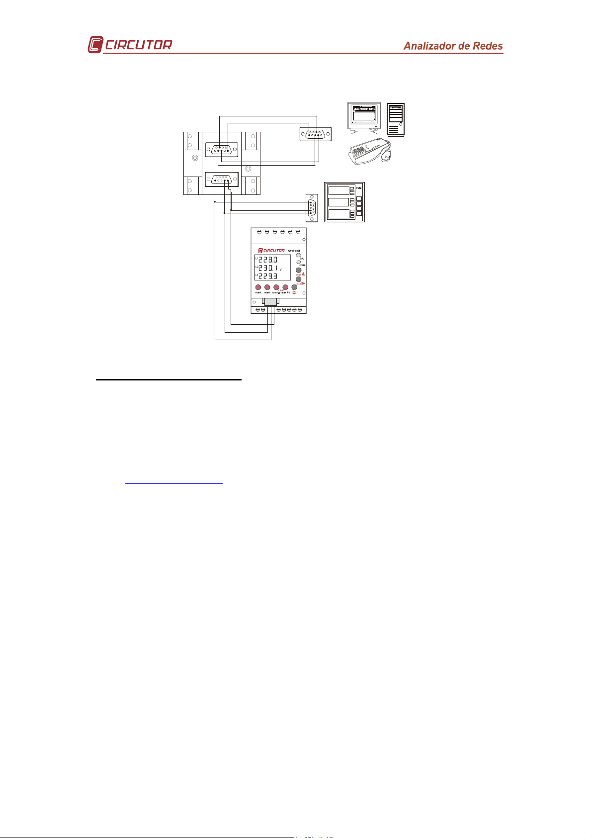
6.2 RS485 Connection diagram
RS-232
A1
RS-485
2
512
5
7
3
-232 / RS-485
CONVERTIDOR
RS-232 / RS-485
A ( + )
B ( - )
S GND
DB-9
5
7
3
2
5
2
1
7 TECHNICAL SERVICE
In the event of any equipment failure or any operational queries please contact the
technical service of CIRCUTOR S.A.
CIRCUTOR S.A. - After sales service.
Vial Sant Jordi, s/n
08232 - Viladecavalls.
Tel. - +34.93.745.29.00
Fax - +34.93.745.29.14
E-mail -
medida@circutor.es
Page 26 of 26
 Loading...