

Page 1
Three-phase power analyzer
1ZD4
and power quality
USER's MANUAL
(M98206501-03-15A)
Page 2
ADVERTENCIAS / SIMBOLOS
PELIGRO
CVMk2
Una conexión incorrecta del equipo puede producir la muerte, lesiones
graves y riesgo de incendio. Lea y entienda el manual antes de conectar
el equipo. Observe todas las instrucciones de instalación y operación
durante el uso de este instrumento.
La instalación, operación y mantenimiento de este instrumento debe
ser efectuado por personal cualicado solamente. El Código Eléctrico
Nacional define a una persona cualificada como "una que esté
familiarizada con la construcción y operación del equipo y con los riesgos
involucrados".
ATENCIÓN
WARNINGS / SYMBOLS
DANGER
Consultar el manual de instrucciones antes de utilizar el equipo.
En el presente manual, si las instrucciones precedidas por este símbolo no
se respetan o realizan correctamente, pueden ocasionar daños personales
o dañar el equipo y /o las instalaciones.
Death, serious injury, or re hazard could result from improper connection
of this instrument. Read and understand this manual before connecting this
instrument. Follow all installation and operating instructions while using this
instrument.
Installation, operation, and maintenance of this instrument must be
performed by qualied personnel only. The National Electrical Code denes
a qualied person as “one who has the skills and knowledge related to the
construction and operation of the electrical equipment and installations, and
who has received safety training on the hazards involved.”
ATTENTION
2
Consult the instruction manual before using the equipment.
In this manual, if the instructions preceded by this symbol are not met or
done correctly, can cause personal injury or equipment damage and / or
facilities.
Page 3
CVMk2
AVERTISSEMENT / SYMBOLES
DANGER
ATTENTION
Un branchement incorrect de l’appareil peut entraîner la mort ou des lésions
graves et peut provoquer un incendie. Avant de brancher votre appareil,
lisez attentivement le manuel et assurez-vous de bien avoir compris toutes
les explications données. Respectez toutes les instructions concernant le
mode d’installation de l’appareil et son fonctionnement.
L’installation, le fonctionnement et la maintenance de cet appareil doivent
être réalisés uniquement par du personnel qualié. Le code électrique
national dénit en tant que personne qualiée "toute personne connaissant
le montage et le fonctionnement de l’appareil ainsi que les risques que
ceux-ci comportent ".
Consulter le manuel d’instructions avant d’utiliser l’appareil
Si les instructions suivantes, précédées dans le manuel d’un symbole,
ne sont pas respectées ou sont réalisées incorrectement, elles pourront
provoquer des dommages personnels ou abîmer l’appareil et/ou les
installations
AVVERTENZE / SIMBOLI
PERICOLO
ATTENZIONE
Un collegamento errato del dispositivo può provocare morte, lesioni
gravi nonché rischio di incendio. Prima di collegare il dispositivo
leggere attentamente il manuale. Osservare tutte le istruzioni relative
all’installazione e all’operatività durante l’uso di questo strumento.
L’installazione, operatività e manutenzione di questo strumento devono
essere realizzate solamente da personale qualicato. Il Codice Elettrico
Nazionale denisce una persona qualicata come “colui che ha familiarità
con la costruzione e operatività del dispositivo e con i rischi che ne
possano derivare”.
Consultare il manuale di istruzioni prima di utilizzare il dispositivo
Qualora le istruzioni riportate nel presente manuale precedute da questo
simbolo non vengano osservate o realizzate correttamente, possono
provocare danni personali o danneggiare il dispositivo e/o gli impianti.
3
Page 4
WARNHINWEISE / SYMBOLE
CVMk2
GEFAHR
ACHTUNG
Durch einen nicht sachgemäßen Anschluss der Anlage können Tod,
schwere Verletzungen und Brandrisiko hervorgerufen werden. Bevor Sie
die Anlage anschließen, lesen Sie bitte das Handbuch durch und machen
Sie sich dessen Inhalt klar. Beachten Sie bei Einsatz dieses Instrumentes
sämtliche Installations- und Betriebshinweise.
Installation, Betrieb und Wartung dieses Instrumentes müssen
ausschließlich von entsprechend qualiziertem Personal vorgenommen
werden. Von dem nationalen Elektrocode wird eine qualizierte Person als
jemand deniert, “der mit der Konstruktion und dem Betrieb einer Anlage
und der damit verbundenen Risiken vertraut ist“.
Vor Inbetriebnahme der Anlage ist das Handbuch zu lesen.
Werden die in dem vorliegenden Handbuch mit diesem Symbol
versehenen Hinweise nicht beachtet oder falsch verstanden, können
Personenschäden und Schäden an der Anlage und/oder den Installationen
verursacht werden.
ADVERTÊNCIAS / SÍMBOLOS
PERIGO
ATENÇÃO
Uma ligação incorrecta do equipamento pode provocar a morte, lesões
graves e risco de incêndio. Leia e compreenda o manual antes de ligar
o equipamento. Observe todas as instruções de instalação e operação
durante o uso deste aparelho.
A instalação, operação e manutenção deste aparelho devem ser levadas a
cabo exclusivamente por pessoal qualicado. O Código Eléctrico Nacional
define uma pessoa qualificada como "uma pessoa que se encontre
familiarizada com a construção e operação do equipamento assim como
com os riscos inerentes”
Consultar o manual de instruções antes de utilizar o equipamento.
No presente manual, se as instruções que precedem este símbolo
não forem respeitadas ou realizadas de forma correcta, podem ocorrer
ferimentos pessoais ou danos no equipamento e/ou nas instalações.
4
Page 5

CVMk2
INDICE MANUAL
1. INTRODUCTION
1.1 DESCRIPTION ......................................................................................................... 11
1.2 TYPES AVAILABLE ................................................................................................12
1.3 EXPANSION CARDS ............................................................................................. 13
1.4 CODING FOR OTHER PARAMETERS .................................................................. 13
1.5 ANALYSIS PARAMETERS .....................................................................................14
1.6 ACCESORIES..........................................................................................................14
2. INSTALLATION
2.1 ITEMS TO VERIFY UPON RECEPTION.................................................................15
2.2 ASSEMBLY SITE ..................................................................................................... 15
ENVIRONMENTAL CONDITIONS ............................................................................. 15
CONSIDERATIONS ................................................................................................... 15
2.3 INSTALLATION METHODS ....................................................................................16
2.3.1 PROCEDURE ................................................................................................... 16
2.4 SYSTEM CONNECTION ......................................................................................... 18
2.4.1 AUXILIARY POWER SUPPLY .......................................................................... 18
2.4.2 RATED VOLTAGE IN VOLTAGE MEASURING CIRCUIT ................................18
2.4.3 RATED CURRENT IN CURRENT MEASURING CIRCUIT.............................. 18
2.4.4 WORKING CONDITIONS ................................................................................. 18
2.4.5 SAFETY ............................................................................................................ 19
2.4.6 TECHNICAL FEATURES .................................................................................. 19
2.5 TERMINALS DESCRIPTION ..................................................................................20
2.5.1 TAG FOR VOLTAGE AND CT CONNECTIONS ............................................... 20
2.5.2 POWER SUPPLY AND COMMUNICATIONS TAG .......................................... 20
2.6 MEASURING INPUT CONNECTION DIAGRAMS ................................................. 21
2.6.1 - 4 CT AND 5 VOLTAGE REFERENCES ......................................................... 21
2.6.2 - 4 CT AND 4 VOLTAGE REFERENCES ......................................................... 21
2.6.3 - 3 CT AND 4 VOLTAGE REFERENCES ......................................................... 22
2.6.4 - 3 CT AND 3 VOLTAGE REFERENCES ......................................................... 22
2.6.5 - 4 CT AND 2 VOLTAGE TRANSFORMERS ...................................................23
2.6.6 - 3 CT AND 2 VOLTAGE TRANSFORMERS ...................................................23
5
Page 6

2.6.7 - 2 CT AND 2 VOLTAGE TRANSFORMERS ...................................................24
2.7 POWER SUPPLY CONNECTION DIAGRAM ......................................................... 24
3. OPERATION
3.1 DESCRIPTION OF DEVICE .................................................................................... 25
3.1.1 FRONTAL VIEW ............................................................................................... 25
3.1.1.a. Display ...................................................................................................... 26
3.1.1.b. Function buttons ....................................................................................... 26
3.1.1.c. Navigation buttons .................................................................................... 26
3.1.1.d. SET button ................................................................................................. 26
3.1.1.e. Upper and lower menus ........................................................................... 26
3.1.1.f. Module name ............................................................................................. 27
CVMk2
3.1.1.e. Icons ......................................................................................................... 27
3.2. START-UP............................................................................................................... 28
4. CONFIGURATION
4.1 MEASURING ........................................................................................................... 29
4.2. QUALITY ................................................................................................................30
4.2.1. QUALITY .......................................................................................................... 31
4.2.2. EVENTS........................................................................................................... 32
4.3. DEMAND ...............................................................................................................34
4.4 TARIFFS .................................................................................................................. 35
4.5 DELETE ................................................................................................................... 36
4.6 COMMUNICATIONS ................................................................................................ 37
4.7 EXPANSION CARDS .............................................................................................. 38
4.7.0. INSERTING EXPANSION CARDS .................................................................. 38
4.7.1. 8 DIGITAL INPUTS AND 8 DIGITAL OUTPUTS ............................................. 40
4.7.1.1. Alarm configuration .................................................................................. 41
4.7.1.2. Digital outputs configuration .................................................................... 43
4.7.1.3. Digital inputs configuration ...................................................................... 44
4.7.1.4. Expansion card parameters ..................................................................... 46
4.7.1.5. Features ................................................................................................... 46
4.7.2 - 8 DIGITAL INPUTS AND 4 RELAY OUTPUTS ............................................. 47
4.7.2.1. Alarm configuration .................................................................................. 48
6
Page 7

CVMk2
4.7.2.2. Relay outputs configuration ..................................................................... 50
4.7.2.3. Digital inputs configuration ....................................................................... 51
4.7.2.4. Card Connections ..................................................................................... 52
4.7.2.5. Expansion card parameters ..................................................................... 53
4.7.2.6. Features ................................................................................................... 53
4.7.3 - 8 ANALOGUE INPUTS AND 4 ANALOGUE OUTPUTS ............................... 54
4.7.3.1. Analogue outputs configuration ............................................................... 55
4.7.3.2. Analogue inputs codes ............................................................................ 56
4.7.3.3. Analogue inputs configuration ................................................................. 57
4.7.3.4. Expansion card parameters ..................................................................... 59
4.7.3.5. Features ................................................................................................... 59
4.7.4 - ETHERNET AND μSD MEMORY .................................................................. 60
4.7.4.1. Network and communications Protocol .................................................... 61
4.7.4.2. IP Address Configuration ......................................................................... 61
4.7.4.3. μSD card configuration ............................................................................ 63
4.7.4.4. μSD Card parameters .............................................................................. 63
4.7.4.5. Expansions card icons ............................................................................. 64
4.7.4.6. Ethernet card features ............................................................................. 64
4.7.5 - μSD MEMORY ............................................................................................... 65
4.7.5.1. μSD Card configuration ............................................................................ 65
4.7.5.2. μSD card parameters ............................................................................... 66
4.7.5.3. Expansion card icons ............................................................................... 67
4.7.5.4. Ethernet output features .......................................................................... 67
4.7.6 - 4 ± 5 MA ANALOGUE AND STATIC OUTPUTS ............................................ 68
4.7.6.1. ± 5 mA analog outputs card configuration ................................................68
4.7.6.2. ± 5 mA analog outputs configuration ........................................................ 69
4.7.6.3. Alarm configuration ................................................................................... 69
4.7.6.4. Static outputs configuration ...................................................................... 71
4.7.6.5. Outputs wiring ........................................................................................... 71
4.7.6.6. Technical Features ................................................................................... 72
4.7.7 - PROFIBUS COMMUNICATIONS CARD........................................................ 73
4.7.7.1. Profibus card configuration ....................................................................... 73
7
Page 8

4.7.7.2. Card parameters .......................................................................................73
4.7.7.3. Slave number configuration ...................................................................... 74
4.7.7.4. Leds information ....................................................................................... 75
4.7.7.5. Profibus connector ....................................................................................75
4.7.7.6. GSD Modules ...........................................................................................76
5. OTHER SYSTEM CONFIGURATIONS
5.1 PREFERENCES ...................................................................................................... 77
5.1.1 SCREEN ........................................................................................................... 77
5.1.2 CLOCK / TEMPERATURE ............................................................................... 78
5.1.3 SECURITY ........................................................................................................ 79
CVMk2
5.2. TOOLS .................................................................................................................... 80
5.2.1 DEVICE............................................................................................................. 80
5.3 MODULES ............................................................................................................... 81
5.3.1 LIST .................................................................................................................. 81
5.3.2 SETUP .............................................................................................................. 83
6. DISPLAY SCREENS
6.1 MEASURING ........................................................................................................... 84
6.1.1 MAIN ................................................................................................................. 84
6.1.1.1. System information ................................................................................... 84
6.1.1.2. Maximums ................................................................................................ 87
6.1.1.3. Minimums ................................................................................................. 88
6.1.2 PHASE-NEUTRAL VOLTAGE ......................................................................... 89
6.1.2.1. Voltage waveform display ......................................................................... 90
6.1.2.2 Voltage phasors display ............................................................................91
6.1.3 PHASE-PHASE VOLTAGE ............................................................................... 92
6.1.4 CURRENT ........................................................................................................ 93
6.1.4.1. Current waveform display ......................................................................... 94
6.1.4.2 Current phasors display ............................................................................ 95
6.1.5 POWERS .......................................................................................................... 96
6.1.5.1 Active power .............................................................................................. 96
6.1.5.2 Inductive Power ......................................................................................... 96
6.1.5.3 Capacitive Power .......................................................................................97
8
Page 9

CVMk2
6.1.5.4 Apparent Power ......................................................................................... 98
6.1.5.5 Total Power................................................................................................ 99
6.1.6, POWER FACTOR .........................................................................................100
6.1.7 COS j ........................................................................................................ 100
6.2. DEMAND ............................................................................................................. 103
6.3 ENERGY ...............................................................................................................104
6.3.1 PRESENT ENERGY ...................................................................................... 104
6.3.2 MONTH ENERGY .......................................................................................... 105
6.3.3 YEARLY ENERGY .......................................................................................... 105
6.4 EXPANSION CARDS ........................................................................................... 106
6.4.1 CARD WITH 8 DIGITAL INPUTS / 8 OUTPUTS ........................................... 106
6.4.2 CARD WITH 8 RELAY INPUTS / 4 OUTPUTS.............................................. 107
6.4.3 CARD WITH 8 ANALOGUE INPUTS / 4 OUTPUTS .....................................107
6.4.4 μSD-ETHERNET AND μSD MEMORY CARD ............................................... 108
6.4.5 μSD MEMORY CARD .................................................................................... 108
6.4.6 ANALOGUE ± 5 MA AND STATIC OUTPUTS CARD .................................... 109
6.4.7 PROFIBUS COMMUNICATIONS CARD ........................................................ 110
7. QUALITY
7.1 HARMONICS ......................................................................................................... 111
7.1.1 VOLTAGE THD ............................................................................................... 112
7.1.2 CURRENT THD .............................................................................................. 113
7.1.3 VOLTAGE HARMONICS ................................................................................ 114
7.1.4 CURRENT HARMONICS ............................................................................... 116
7.2. DISTURBANCES ................................................................................................ 118
7.2.1 FLICKER ......................................................................................................... 118
7.2.1.1 PST Calculation ....................................................................................... 119
7.2.1.2 Real Time Weighted Average Calculation............................................... 119
7.2.2 K FACTOR .....................................................................................................120
7.2.3 UNBALANCE AND ASYMMETRY ................................................................. 121
7.2.4 CREST FACTOR ............................................................................................ 122
8. COMMUNICATIONS
8.1. MODBUS/RTU PROTOCOL © ............................................................................123
9
Page 10

CVMk2
8.2. CONNECTION DIAGRAM ....................................................................................124
8.2.1. CIRCUTOR INTELLIGENT CONVERTER .................................................... 124
8.2.2. TCP2RS CONVERTER ................................................................................. 125
8.2.3. USB CONVERTER ........................................................................................ 126
8.2.4 SCREEN-MODULES COMMUNICATIONS BUS ........................................... 127
8.3. MODBUS/RTU © MEMORY MAP ........................................................................ 128
8.3.1 ELECTRIC VARIABLES ................................................................................ 128
8.3.2. CURRENT ENERGY VARIABLES ................................................................131
8.3.3. ENERGY VARIABLES FROM PREVIOUS PERIODS .................................. 133
8.3.4. ENERGY VARIABLES FOR THE PREVIOUS YEAR ................................... 135
8.3.2. MAXIMUM DEMAND VARIABLES ................................................................ 137
8.3.6. VOLTAGE HARMONICS VARIABLES...........................................................139
8.3.7. CURRENT HARMONICS VARIABLES ......................................................... 140
8.3.8. DIGITAL INPUT EXPANSION CARD VARIABLES........................................141
8.3.9. ANALOGUE INPUT EXPANSION CARD VARIABLES ................................. 142
8.4. RS-485 NETWORK FEATURES .......................................................................... 143
9 . MAINTENANCE AND CALIBRATION
9.1 MAINTENANCE .....................................................................................................143
10. FEATURES
10.1. STANDARDS ...................................................................................................... 144
10.2. TECHNICAL FEATURES ................................................................................... 144
10.3. OTHER CONCEPTS ..........................................................................................146
10.3.1 UNBALANCE COEFFICIENT (KD) ..............................................................146
10.3.1 ASYMMETRY COEFFICIENT (KA) .............................................................. 146
10
10.3.3 FLICKER ....................................................................................................... 146
10.3.4. K FACTOR ................................................................................................... 147
10.3.5. CREST FACTOR .........................................................................................147
11. SOFTWARE
11.1 POWER STUDIO SCADA. .................................................................................. 149
Page 11

CVMk2
1. INTRODUCTION
This manual is intended to be used as a guide in the
installation, conguration and operation of the CVMk2
network analyzer, for optimising the system's benets.
Read with attention and follow the warnings and
symbols.
1.1 DESCRIPTION
CVMk2 measures, calculates and displays the primary electric parameters in balanced or
unbalanced three-phase industrial networks.
True RMS values are measured using three alternating voltage inputs, two voltage references
(neutral and ground), and four current inputs to measure secondaries …/1A or …/5A, coming
from the outside current transformers. It should be considered that when secondary .../1 is
selected, the calculation is made by the software.
The CVMk2 network and power supply quality analyzer is a programmable measuring
instrument. It offers a wide variety of uses, which can be selected from the instrument's
conguration menus. Prior to using the analyzer, read the following sections carefully: power
supply, connection and conguration. Then, choose the best operating method for obtaining
the desired data.
CVMk2 permits viewing the electric parameters on a backlit 1/4 VGA graphical display. Real
time, maximum or minimum electric parameters can be viewed by pressing the corresponding
key. Internal processor shows more than 500 electric parameters via the display screen and
communication. Said parameters may be fed from a single or three phase system.
CVMk2 has the following important features:
• Outside dimensions 144x144x116 mm.
• Mounted on a DIN rail (measurement module) with display screen on panel (96x96 mm,
144x144 mm or 103 mm (4") diameter hole.
• True RMS value (TRMS) measurement.
• Class 0,2 or 0,5 in Power and Energy (*).
• Real time, maximum and minimum values for each parameter with date and time.
• 1/4 VGA graphical display.
• RS-485 (Modbus/RTU©) communication incorporated.
• Possible to congure the display screen as the MASTER for 32 measurement modules.
• Multi-tariff equipment (allows to program up to 9 tariff)
• Memory of present, month and annual energy consumed and generated.
• Graphical display of wave forms and voltage and current phasors.
• 8 digit (100 GW·h) counter to track energy consumed and energy generated.
• Recording of power supply quality events on voltage.
• Expandable with inputs/outputs expansion card.
• Implemented in the CIRCUTOR energy management software, PowerStudio Scada.
http://powerstudio.circutor.com
(*) Depending on the model
INTRODUCTION
11
Page 12
CVMk2 has no battery. When supply falls down the analyzer do not store electrical
parmeters and no quality events. Is very important to guarantee the supply of the
device from an interrupted source (Batery, SAI, ...)
1.2 TYPES AVAILABLE
CVMk2
CODE
M54400 CVMk2-ITF-405
M54402 CVMk2-ITF-402
TYPE
VALID FOR .../5 AND .../1 A TRANSFORMERS
THREE PHASE 50...60HZ
TRUE RMS VALUE (TRMS)
INSULATED CURRENT INPUTS ITF
COMMUNICATION PORTS (*)
EXPANSION SLOTS
ANALYSIS OF VOLT & CURR (50º) HARMONICS.
DISTURBANCE DETECTION
MULTI-TARIFF EQUIPMENT (9 TARIFF)
4 QUADRANTS
VOLTAGE AND CURRENT WAVE FORMS
CLASS 0.5 (POWER AND ENERGY)
● ● ● ● 2 3 ● ● ● ● ● ●
● ● ● ● 2 3 ● ● ● ● ● ●
CLASS 0.2 (POWER AND ENERGY)
NETWORK PROTOCOL
RS485 Modbus-RTU
RS485 Modbus-RTU
Measurement modules (without display)
M54410 M-CVMk2-ITF-405
M54412 M-CVMk2-ITF-402
(*) COM1 to communicate only with the display and COM2 bus RS-485 Modbus/RTU
● ● ● ● 2 3 ● ● ● ● ● ●
● ● ● ● 2 3 ● ● ● ● ● ●
RS485 Modbus-RTU
RS485 Modbus-RTU
COMMUNICATION PROTOCOL
INTRODUCTION
12
To insure the system class, it is recommended to use type TCH high precision
transformers. See the M7 family of current transformers.
Page 13
CVMk2
1.3 EXPANSION CARDS
CVMk2 has a wide range of expansion cards that enable users to interact with the system or
tocommunicate with other protocols. The expansion cards and corresponding codes are in the
following table
CODIGO I/O DESCRIPCIÓN
M54501 8I/8O
8 opto-coupled digital inputs
8 optocoupled transistor digital outputs
M54502 8I/4O
M54503 8I/4O
M54504 Ethernet (Modbus/TCP) + μSD Memory
M54506 μSD Memory
M54507 4O/4O
M5450A Probus DP
8 analogue inputs (0/4...20 mA)
4 analogue outputs (0/4...20 mA)
8 opto-coupled digital inputs
4 relay outputs (3 NO + 1 NO/NC)
4 analogue outputs of ± 5mA
4 opto-coupled digital outputs
1.4 CODING FOR OTHER PARAMETERS
For coding attributes or special features or power measuring equipment, or as modules, you
must use the following encoding table.
M 5 4 X X X 0 0 X X X
Code
Voltage supply
(High Voltage)
Voltage measured
(TM)
Current input (1) exterior ITF (WG20) (**) 3
85 ... 265 V a.c.
100 ... 300 V c.c
SDC 24...90 V c.c 8
Standard 300 / 520 V a.c 0
(1) 63,5 / 110 V a.c. (**) 1
(1) 500 / 866 V a.c. 3
Internal
code
0
(1) Those devices are not under UL
(**) The extent to voltage 110 Vac and / or measured using external transformers WG20
measuring transformer secondary is only possible in the measurement module 402, model code
M54412. If asked this particular module should know that the display is not included and
must be requested separately. (see paragraph 1.6 ACCESSORIES)
INTRODUCTION
13
Page 14
CVMk2
1.5 ANALYSIS PARAMETERS
PARAMETER UNIT L1 L2 L3 N III
Ph-N VOLTAGE V ● ● ● ● ●
Ph-Ph VOLTAGE V ● ● ● ●
CURRENT A ● ● ● ● ●
FREQUENCY Hz ●
ACTIVE POWER (Consumption and Generation) kW ● ● ● ●
INDUCTIVE POWER (Consumption and Generation) kvar L ● ● ● ●
CAPACITIVE POWER (Consumption and Generation) kvar C ● ● ● ●
APPARENT POWER (Consumption and Generation) kV·A ● ● ● ●
POWER FACTOR PF ● ● ● ●
COS j
MAXIMUM ACTIVE POWER DEMAND Pd ●
MAXIMUM APPARENT POWER DEMAND Pd ●
MAXIMUM CURRENT DEMAND Pd ● ● ● ●
NEUTRAL LINE CURRENT I
VOLTAGE THD (RMS AND FUNDAMENTAL) U THD ● ● ● ●
CURRENT THD (RMS AND FUNDAMENTAL) I THD ● ● ● ●
VOLTAGE HARMONICS 2nd...50
CURRENT HARMONICS 2nd...50
ACTIVE ENERGY (Consumption and Generation) kW·h ●
INDUCTIVE ENERGY (Consumption and Generation) kvar·h L ●
CAPACITIVE ENERGY (Consumption and Generation) kvar·h C ●
APPARENT ENERGY (Consumption and Generation) kV·A·h ●
TOTAL ACTIVE ENERGY and Tariff (Consum. and Gen.) kW·h ●
TOTAL INDUCT. ENERGY and Tariff (Consum. and Gen.) kvar·h L ●
TOTAL CAPAC.. ENERGY and Tariff (Consum. and Gen.) kvar·h C ●
TOTAL APPARENT ENERGY and Tariff (Consum. and Gen.) kV·A·h ●
FLICKER (WA and PST) Wa / Pst ● ● ●
K-FACTOR (current) ● ● ●
CREST FACTOR (voltage) ● ● ●
UNBALANCE (voltage and current) ● ● ●
ASYMMETRY (voltage and current) ● ● ●
th
th
SCREENS PARAMETERS
PHASE DIFFERENCE BETWEEN VOLTAGES
PHASE DIFFERENCE BETWEEN CURRENTS
DIFFERENCE BETWEEN VOLTAGES AND CURRENTS
WAVEFORMS ● ● ●
Cos j ● ● ● ●
N
harm V ● ● ● ●
harm A ● ● ● ●
PHASORS ● ● ●
1.6 ACCESORIES
INTRODUCTION
14
CODE DESCRIPTION
M5ZZH1 Connector of CVMk2
M54420 Display of CVMk2
Page 15

CVMk2
2. INSTALLATION
This manual provides information and warnings that the user should heed to guarantee that the
system operates safely and is kept in good conditions for safe use.
If the system is handled in a way contrary to the manufacturer's specications, it
may not be protected.
2.1 ITEMS TO VERIFY UPON RECEPTION
Verify the following upon receiving the instrument:
• The device meets specications in the order.
• The device was not damaged during transport.
• The instrument comes with the quick guide and/or the user's manuals.
In order to safely use the CVMk2, the personnel in charge of installing or
handling it must follow the standard safety guidelines and heed all warnings
provided in the instruction manual.
This analyzer should be installed and maintained by qualied personnel.
2.2 ASSEMBLY SITE
ENVIRONMENTAL CONDITIONS
To guarantee its optimal operation, it is recommended to use the system at between -10 and
40 ºC with relative humidity between 5 and 95%, but with no condensation. Temperature range
according UL. In internal testing until 50 ºC
CONSIDERATIONS
The CVMk2 should be mounted in a distribution cabinet that protects the system from
environmental contamination such as oil, moisture, dust, corrosive vapours or other volatile
substances.
When it is likely that the system has lost its safety guards (due to visible
damages), it should be disconnected from the auxiliary power supply and the
input supplies. In this case, contact a qualied tech support.
The system can be installed in one of two basic ways:
• As a compact system in a distribution cabinet, installing at the panel.
• As a modular system, installing the display on the panel and the measuring
module on DIN 46277 (EN 50022) rail.
INTRODUCTION
15
Page 16
CVMk2
2.3 INSTALLATION METHODS
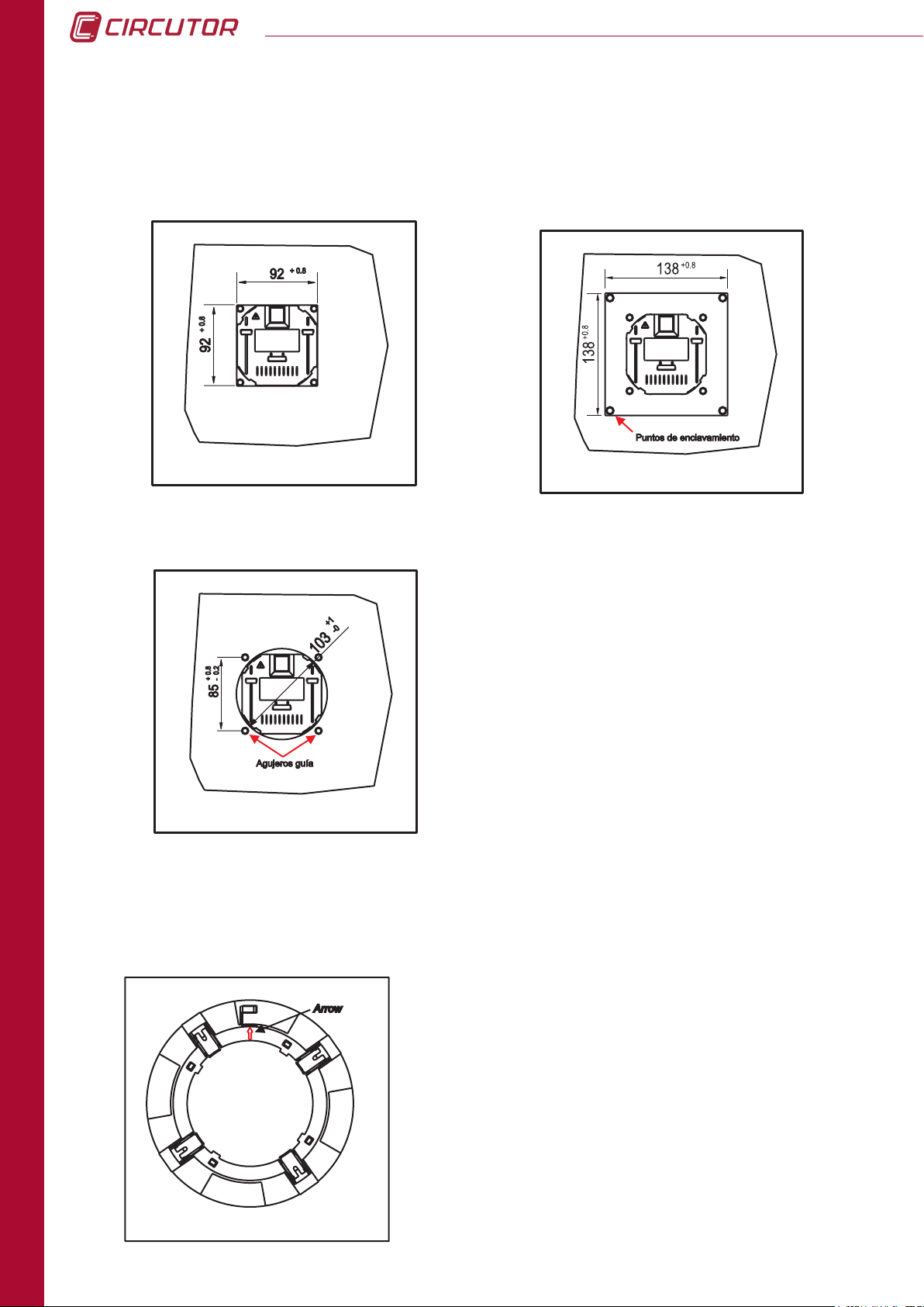
The gures illustrate the different installation possibilities, permitted by the display screen
design. The system design facilitates screwing the panel on (92
+0.8
mm and a 103 mm diameter hole).
+0.8
+ 92
+0.8
mm, 138
+0.8
+ 138
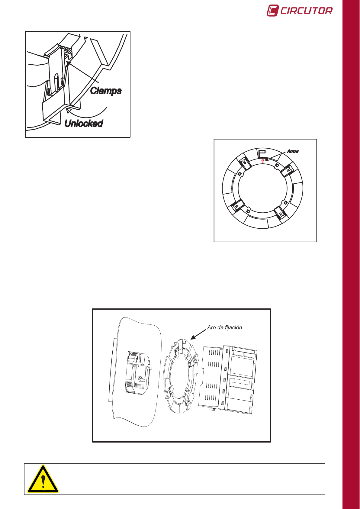
2.3.1 PROCEDURE
The figures illustrate how to mount the front part
(display) in a 92x92 mm (3,62 x 3,62 in) hole, a 103
mm (4,06 in) diameter hole and in a 138x138 mm (
5,43 in) hole.
After inserting the front part, install the mount ring,
making sure that the tabs are not blocked (see
procedure). Also, assure that the white arrow, which
indicates the point where the communications cable
and the RJ-45 display screen power supply cable
run out, lines up with the arrow on the measuring
equipment.
INTRODUCTION
16
The tabs are components used to fasten the system to
the panel. When mounting the system, the tabs must be
free, and unblocked, so that as pressure is applied to
the mount ring the tabs go over the clamp zipper teeth.
Similarly, to dismount the panel display the tabs should
be blocked, i.e. opened prior to dismounting.
Page 17
CVMk2
A zoomed view of the previous image is provided in the
figure. It provides a detailed view of the movements
necessary to lock and unlock CVMk2 display screen
mount ring.
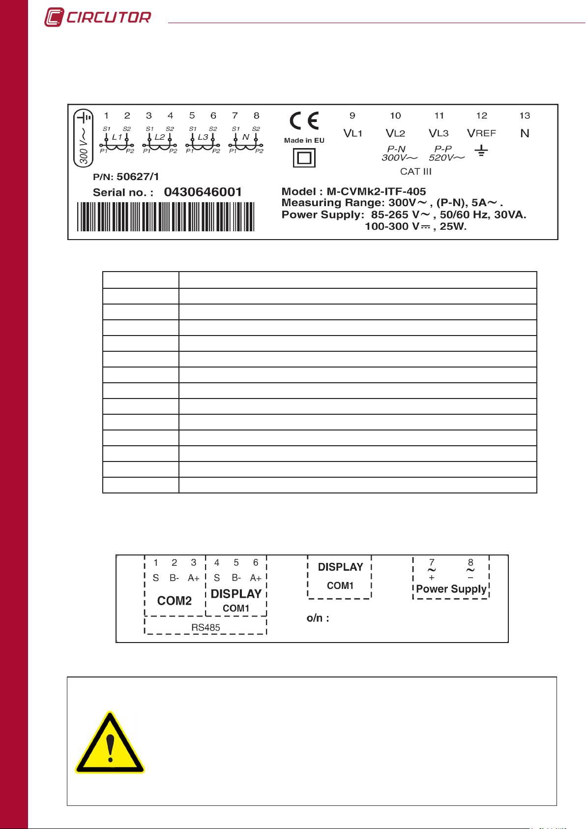
As shown in the gure, the guide arrow should point
upward and line up with the arrow found on the rear of
the viewer or display screen. The arrow points to the
position where the RJ-45 communications cable and
the display screen power supply cables run out.
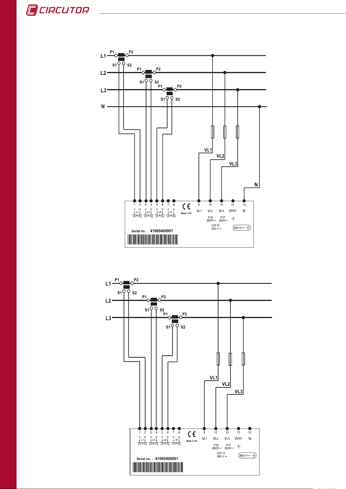
The mount diagram is shown in the following gure. The measuring unit can then be mounted
on the ring behind the display screen, or it can be installed on a DIN rail and communicate
with the display screen via a communication cable and transparent RJ-45 power supply. (See
Table 3.1, physical description).
To install the screen in a panel as shows the 2.3 installations methods, you
have to use a at surface of a type 1 enclosure.
INSTALLATION
17
Page 18

2.4 SYSTEM CONNECTION
Before connecting the equipment, the following points should be veried:
2.3.1 Auxiliary Power Supply Features
2.3.2 Maximum Voltage in the Voltage Measuring Circuit
2.3.3 Maximum Current in the Current Measuring Circuit
2.3.4 Working Conditions
2.3.5 Safety
2.4.1 AUXILIARY POWER SUPPLY
CVMk2
Standard power supply 85...265
100...300
V a.c.
V d.c.
Frequency 50...60 Hz
Optional power supply 24...90 V d.c.
2.4.2 RATED VOLTAGE IN VOLTAGE MEASURING CIRCUIT
Standard rated voltage (*) 300 / 520 V
Other voltages (*) 500 / 866 V
(*) Current limited. Máximum 0.6 V·A
Rated frequency 45,00...65,00 Hz
U
= UN x 1.2
max
f-n
f-n
/ V
/ V
f-f
f-f
18
INSTALLATION
2.4.3 RATED CURRENT IN CURRENT MEASURING CIRCUIT
Secondaries .../5A (*) 5 A a.c.
Secondaries .../1A (*) 1 A a.c.
(*) limited in voltage
I
= IN x 1.2
max
2.4.4 WORKING CONDITIONS
Operating temperature -10...+40 ºC
Relative Humidity 5...95 %
Page 19

CVMk2
2.4.5 SAFETY
Designed for CAT III 300/520 Vac installations in accordance with EN-61010.
Protected against electrical shock by class II double insulation.
Designed and identied by the distinctive CE marks.
To increase system capacity with expansion cards prior to handling, modify
its connections or replace equipment; the power supply should be shut off
and the inputs disconnected from the CVMk2. Handling the system while it
is powered up is dangerous.
2.4.6 TECHNICAL FEATURES
VOLTAGE INPUTS
Measuring range
Frequency 45…65 Hz
Maximum measured voltage 360 Vac
Acceptable overvoltage 750 Vac
Maximum Consumption (limited current) < 0.6 V•A
CURRENT INPUTS
Measuring range from 1 to 120% of In for In = 5 A
Secondary for the TCs (In) 1 or 5 A
Primary current measured Programmable < 30.000 A
Acceptable overload 6 A continuous, 100 A t<1 s
Consumption < 0.45 V•A
AUXILIARY POWER SUPPLY
Power supply
MECHANICAL
Maximum torque 0.8 Nm
Maximum wire rigid diameter 4.5 mm2 (AWG 11)
from 5 to 120% of Un for Un = 300 Vac (f-N)
from 5 to 120% of Un for Un = 520 Vac (f-f)
85 to 265 V ac (50...60 Hz) (consumption < 30 V·A)
90 to 300 V dc (consumption < 25 W)
When the system is connected, it may be dangerous to touch the terminals.
Additionally, dangerous parts may be exposed when covers are opened or
when protective components are removed. The system should not be used
until it is completely installed.
INSTALLATION
19
Page 20
2.5 TERMINALS DESCRIPTION
2.5.1 TAG FOR VOLTAGE AND CT CONNECTIONS
TERMINAL DESCRIPTION
1 Current transformer, L1 phase S1 connection
2 Current transformer, L1 phase S2 connection
3 Current transformer, L2 phase S1 connection
4 Current transformer, L2 phase S2 connection
5 Current transformer, L3 phase S1 connection
6 Current transformer, L3 phase S2 connection
7 Current transformer, neutral line S1 connection
8 Current transformer, neutral line S2 connection
9 L1 phase voltage input
10 L2 phase voltage input
11 L3 phase voltage input
12 Input voltage V
13 Input voltage NEUTRAL LINE
(GND)
REF
CVMk2
INSTALLATION
2.5.2 POWER SUPPLY AND COMMUNICATIONS TAG
Product to be protected by an external fuse, model KTK-1 by
Bussmann, or similar, rated 600V, 1A. It should be provided with a
MCCB or equivalent device to switch off the system from the power
supply circuit. The power supply and voltage measuring circuit is
connected with cable minimum cross section of 1 mm2 (AWG 17). The
current transformer secondary side connection line should have a
minimum cross section of 2 mm2 (AWG 14 Cu) and with a minimum
temperature rating of 60 ºC.
20
Page 21

CVMk2
2.6 MEASURING INPUT CONNECTION DIAGRAMS
2.6.1 - 4 CT AND 5 VOLTAGE REFERENCES
2.6.2 - 4 CT AND 4 VOLTAGE REFERENCES
INSTALLATION
21
Page 22
2.6.3 - 3 CT AND 4 VOLTAGE REFERENCES
CVMk2
2.6.4 - 3 CT AND 3 VOLTAGE REFERENCES
22
INSTALLATION
Page 23

CVMk2
L1
L2
L3
VL1
VL2
VL3
S2
P2
S1
P1
S2
P2
S1
P1
S2
P2
S1
P1
B
A
S2
P2
S1
P1
A
B
aabb
N
S2
P2
S1
P1
L1
L2
L3
VL1
VL2
VL3
S2
P2
S1
P1
S2
P2
S1
P1
S2
P2
S1
P1
B
A
S2
P2
S1
P1
A
B
aabb
2.6.5 - 4 CT AND 2 VOLTAGE TRANSFORMERS
2.6.6 - 3 CT AND 2 VOLTAGE TRANSFORMERS
OPERATION
23
Page 24

2.6.7 - 2 CT AND 2 VOLTAGE TRANSFORMERS
L1
L2
L3
VL1
VL2
VL3
S2
P2
S1
P1
B
A
S2
P2
S1
P1
A
B
aabb
model)
CVMk2
INSTALLATION
2.7 POWER SUPPLY CONNECTION DIAGRAM
The system should be connected to a power supply circuit protected
by fuses with current ratings between 0.5 and 1 A / 600 V (UL listed). It
should be provided with a MCCB or equivalent device to switch off the
system from the power supply circuit. The power supply and voltage
measuring circuit is connected with cable minimum cross section of
1 mm2 (AWG 17). The current transformer secondary side connection
line should have a minimum cross section of 2 mm2 (AWG 14) and with
a minimum temperature rating of 60 ºC.
Power supply
85...265Va.c.
100...300Vc.c.
(Standard
24
Page 25
CVMk2
3. OPERATION
3.1 DESCRIPTION OF DEVICE
The external dimensions of the CVMk2 network analyzer are 144 x 144 x 116 mm. It is
comprised of a display screen and a measuring module. The display screen communicates
with the measuring module via an RJ-45 line, which is "transparent" or direct. The wire layout
is provided in the gure below:
DISPLAY SCREEN MEASURING EQUIPMENT
PIN SIGNAL SIGNAL PIN
1 V+ V+ 1
2 GND GND 2
3 B (-) B (-) 3
4 Shield Shield 4
5 Shield Shield 5
6 A (+) A (+) 6
7 GND GND 7
8 V - V - 8
3.1.1 FRONTAL VIEW
MENUS
MODULE NAME
DISPLAY
SCREEN
ICONS
FUNCTION BUTTONS
NAVIGATION BUTTONS
INSTALLATION
25
Page 26
CVMk2
The front is divided into several parts:
a) Display screen.
b) Function buttons.
c) Navigation buttons.
d) SET button.
e) Upper and lower menus.
f) Module name.
g) Icons.
3.1.1.a. Display
The CVMk2 network analyzer incorporates a 320 x 240 pixel, backlit, 1/4 VGA (QVGA) LCD
monitor. The monitor surface area is 90 x 70 mm2 (4,5 in). The display screen has backlighting
to facilitate reading the parameters when they are presented on the display screen in poor
lighting conditions.
CVMk2 allows program a timer to shut off the backlighting after several seconds have passed.
Said timer can be programmed for 10, 90 or 180 seconds. It is also possible to leave the
backlighting always ON or always OFF.
To access the display screen properties conguration menu, use the left navigation button to
navigate to MENU. Use the SET button or the down arrow button to open the drop-down menu.
Select SYSTEM--PREFERENCES--DISPLAY SCREEN.
WARNING: The maximum working temperature for the 1/4 VGA display screen
is 40 ºC. Operating the system above this temperature can quickly deteriorate
the equipment or lead to permanent malfunctioning.
3.1.1.b. Function buttons
The system has 4 function buttons on the front side (F1, F2, F3 and F4). The function buttons
are used to access the different menus that appear on the bottom of the display.
3.1.1.c. Navigation buttons
26
OPERATION
On the front side, the system has 4 arrow buttons used to navigate through the different menus
that appear on the lower side of the screen. Press the left arrow button to exit at any time the
current menu.
3.1.1.d. SET button
This button is used to access the menu that is selected with the cursor and to conrm any
change before to press OK (F4). Is necessary to press SET to store any chage.
3.1.1.e. Upper and lower menus
The upper and lower menus change based on the current screen. A detailed description of all
the menus and the options in each menu is provided in the upcoming chapters.
Page 27
CVMk2
3.1.1.f. Module name
The measuring module currently being viewed is dened on this part of the display screen. This
is important in facilities where measuring modules are communicating with one single display
screen.
3.1.1.e. Icons
Editable conguration menu (without password).
Conguration menu locked with password.
None of the voltages for the phases are connected, or they are not detected.
Voltage is only detected at the phase 1 input.
Voltage is only detected at the phase 2 input.
Voltage is only detected at the phase 3 input.
Voltage is only detected at the phase 1 and 2 inputs.
Voltage is only detected at the phase 1 and 3 inputs.
Voltage is only detected at the phase 2 and 3 inputs.
Voltage is detected at the phase 1, 2 and 3 inputs.
Correct μSD memory status.
Incorrect μSD memory status.
Extraction of μSD card enabled.
Short circuit or hole detected. This only appears during the event.
Overvoltage detected. This only appears during the event.
Switching detected. This only appears during the event.
There is no consumption and no generation.
Generation
Consumption.
OPERATION
27
Page 28
CVMk2
3.2. START-UP
Before power ON the device, make sure that all the cables are properly connected.
A bad connection can cause serious injuries to the personnel that are working on
the equipment and can damage the equipment.
When power supply is connected to the CVMk2, the system will show an initial presentation
and initialize its internal software indicating the rmware version on the display screen. After a
time of searching, it will also display the rmware versions of the modules that are connected to
the COM 1 DISPLAY port as well as the cards that are inserted in each one of the modules.
Once initialization is complete, the CVMk2 will display the switched module's real time values
on the main screen.
The CVMk2 principal screen changes. This is because the system will keep a memory the
last screen that was viewed for more than 20 seconds before disconnected. This screen will
be displayed the next time the display is turn on except if it is an expansion card screen. They
are not stored in memory.
Once the CVMk2 has been installed, is recommended to restart the meter and the
maximums and minimums of the device. It is possible that the installation process
will produce some recorded parameters outside the range of normal working and
subsequently affect the display of records in graphs or tables.
OPERATION
Page 29
CVMk2
4. CONFIGURATION
The analyzer does not store programming changes that are made until
programming is complete. These changes are conrmed by pressing SET and
after the ok button. If the system is reset before said programming is complete or
if the user exits the menu using the esc button, the conguration settings will not
be stored in memory. To access to the conguration menu, refer to Chapter 4.
Measurement, communication and expansion card parameters (if available) can be modied
from the conguration menu.
To access the conguration inside the MENU, select Setup and conrm with the set key.
The menu on the top of the screen will appear as seen in the following gure.
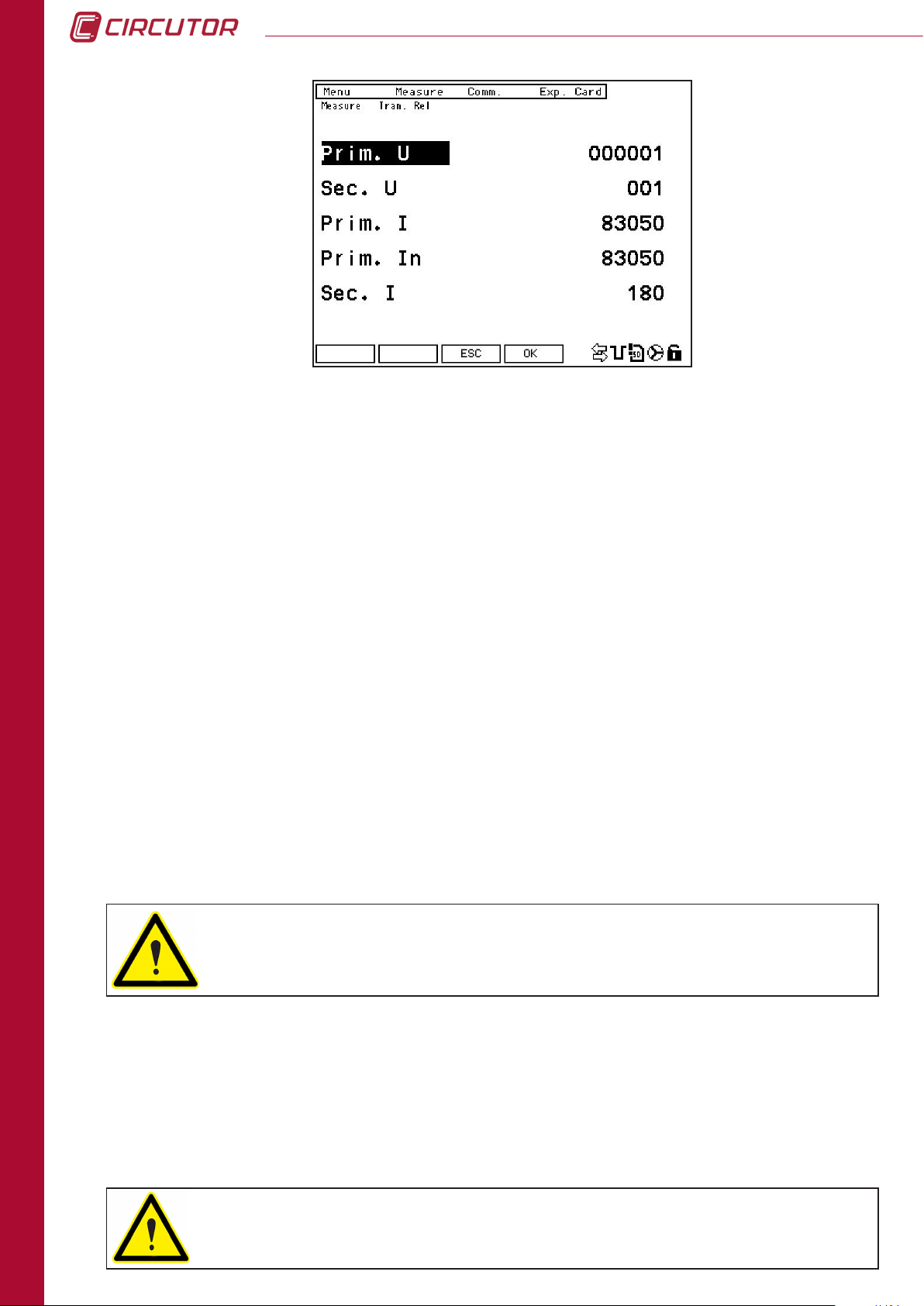
4.1 MEASURING
In the MEASURE menu, the list of voltage and current transformers can be accessed. To modify
the transformer conguration parameters, press the EDIT button (F4).
Position the cursor in the rst line of parameters (primary voltage). Use the up-down arrow
buttons to move the cursor to the desired parameter. Press SET to enter the numeric value to
be modied. The cursor will be positioned over the rst digit, corresponding to the largest value.
Use the left/right arrow buttons to navigate from one digit to another and the up/down arrow
buttons to increase/decrease the value of the digit.
CONFIGURATION
29
Page 30
CVMk2
Parameters that can be congured on this screen follow:
• PRIM. U.: Primary on the voltage transformers. If it does not exist,
program 1. The maximum congurable value is 999999.
• SEC. U.: Secondary on the voltage transformers. If it does not exist,
program 1. The maximum congurable value is a 3 digit number 999.
• PRIM. I.: Primary on the current transformer. The maximum congurable value is 30000.
• PRIM. In.: Primary on the current transformer for the neutral line. The maximum
congurable value is 30000.
The default value is 5. If it is desirable for the CVMk2 to show the neutral line
current that is calculated, congure 0.
• Sec. I.: Secondary on the current transformer. It is possible to program 5 or 1.
To store the modied parameters in memory, press SET and conrm with OK (F4). To exit without
saving changes press ESC (F3).
WARNING: The CVMk2 power calculation is limited according to the
following ratio:
30
CONFIGURATION
(Prim V) x (Prim I) < 45.000.000
4.2. QUALITY
To access the power supply quality parameters conguration screen, position the cursor over
quality and press SET. Two options are provided in the quality menu, Quality and Events.
CVMk2 has no battery. When supply falls down the analyzer do not store electrical
parmeters and no quality events. Is very important to guarantee the supply of the
device from an interrupted source (Batery, SAI, ...)
Page 31

CVMk2
4.2.1. QUALITY
To access the quality parameters conguration menu, go to the quality menu, in the main
conguration menu, and select quality. From the two options provided, select quality.
Parameters that can be congured on this screen are:
• thd calc: To calculate the harmonic distortion rate based on the fundamental, select
FUND. Select RMS to make the calculation based on the RMS value.
• period: Enter the desired period for the registration of the variables. Must be between 1
and 240 minutes. If no memory card available this period applies to the
calculation of icker and STD. If one card μSD external memory
expansion, this period is only to the calculation of icker. The registration of STD
is managed by the Power Studio. Means setup time period (minutes) of
the window of integration.
• nom. freq.: Enter the network rated frequency value. This is used in the icker calculation.
CONFIGURATION
31
Page 32

CVMk2
• nom. v.: Enter the network rated phase-neutral voltage value. If using a voltage
transformer, enter the transformer secondary value. If there is no neutral line,
enter the voltage value as if there was one. This is used for quality events
calculations.
To modify the current values, press EDIT (F4). The cursor will be positioned in the rst line of
parameters. Use the up-down arrow buttons to move the cursor to the desired parameter. Press
SET to enter the corresponding numeric value.
Position the cursor over the rst digit, corresponding to the largest value. Use the left/right
arrow buttons to navigate from one digit to another and the up/down arrow buttons to increase/
decrease the value of the digit where the cursor is currently positioned.
To store the modied parameters in memory, press SET and conrm with OK (F4). To exit without
saving changes press ESC (F3).
If values entered are not within the acceptable range or are not valid, the
modications will not be recorded. The values used prior to the modication will
be restored.
4.2.2. EVENTS
To access the event margins configuration menu, go to the measure menu in the main
conguration menu. Then, select events in the quality menu.
Parameters congured on this screen are in % with respect to the nom. v. from the previous
screen (quality).
Thus, the % value that should be congured for the overvoltage threshold must always be
greater than 100% of the value congured for the nom v. variable on the previous screen (4.2.1.
QUALITY).
32
CONFIGURATION
To modify the current values, press EDIT (F4). The cursor will be positioned in the rst line of
parameters. Use the up-down arrow buttons to move the cursor to the desired parameter. Press
SET to enter in the corresponding numeric value.
Page 33

CVMk2
The cursor will be positioned over the rst digit, corresponding to the largest value. Use the
left/right arrow buttons to navigate from one digit to another and the up/down arrow buttons to
increase/decrease the value of the digit where the cursor is currently positioned.
To save the modied parameters to memory, press OK (F4) before exiting. If saving the changes
is not desired, press ESC (F3).
Parameters that can be congured on this screen are:
• SWELL Thr: This corresponds to the threshold value, in %, to detect an overvoltage event.
• SAG Thr: This corresponds to the threshold value, in %, to detect a hole event.
• iNTEr. Thr: This corresponds to the threshold value, in %, to detect a short circuit event.
• SWELL Hys: Hysteresis, in %, over the programmed value in the detection threshold.
• SAG Hys: Hysteresis, in %, over the programmed value in the detection threshold.
• iNTER. Hys: Hysteresis, in %, over the programmed value in the detection threshold.
The value of the hysteresis is always, in part, more restrictive. It is not a
symmetric hysteresis. The detection value is over the programmed value, as a
%. The hysteresis applies in the disconnection or the disappearance of the event.
If the event is for a maximum (over v Thd), the hysteresis will be applied when
the signal drops. If the event is for a minimum (hole Thd and short circuit Thd),
the hysteresis will be applied when the signal increases again.
Example graph:
Un
Swell Thr.
Sag Thr.
Inter Thr.
110%
V nom
90%
10%
Swell Hys
Sag HysSag Hys
Inter Hys
t0
t1
t2
t3
t4
t
In the graph is showed an example of an Swell voltage in the interval t 0. The time of that
overvoltage event is the time that the signal is over the swell value (usually 110%) plus the time
of the hysteresis for this swell (usually 2%).
CONFIGURATION
33
Page 34

CVMk2
Another example of event are showed in times period t1, t3 and t4. They are Sags. They are
congured usually unther 90% of the nominal voltage.
When the voltage goes down unther 10% it is stored as an interruption. That interruption is
showed in period t2.
Thre quality events has to be longer than 10ms. If the duration is less than 10ms, the event will
not be stored but will affect to the calculus of the average value for that period.
4.3. DEMAND
To access the maximum demand control parameters conguration screen, position the cursor
over DEMAND and conrm by pressing SET.
34
CONFIGURATION
Parameters that can be congured on this screen follow:
Period: Integration window minutes used calculating the maximum demand. Values can
be programmed from 1 up to a maximum of 60.
Win. type: It is possible to select between two window types to calculate the maximum
demand. These are:
• FIXED: Each period duration initializes the maximum demand value. If
programmed for 15 minutes, the measured values are integrated every
15 minutes, and the values for the next 15 minutes are set to zero.
• MOVING: The beginning and end of the integration period moves with each sample
collected. The calculation for maximum demand is made with the
values, in the integration time, each time a new sample is recorded.
To store the modied parameters in memory, press SET and conrm with OK (F4). To exit without
saving changes press ESC (F3).
Page 35

CVMk2
4.4 TARIFFS
WARNING: CVMk2 has an internal clock that you have to congure. The
device will work with this local hour but, if you communicate the device with
Power Studio the local time of the device will be changed to UTC hour.
CVMk2 permits conguring up to 9 tariff. To access the tariff conguration screen, position the
cursor over Tariff and press SET.
Parameters that can be congured on this screen follow:
• No. of Tariff.: The number of tariff. Specify how many different tariff are going to be
congured.
• Synch.: Use the internal clock or calendar to manage tariff, select the CLOCK option. To
use an external signal to change tariff (activating static inputs for a CVMk2
expansion card), select the EXTERNAL option.
It is possible to load a yearly fee calendar to the memory. This calendar can only be saved from
the CIRCUTOR POWER STUDIO SCADA software. The calendar is stored in the memory and
is synchronised with the internal clock.
• No. In.: If EXTERNAL was selected in the previous option, Synch., specify the input for
the expansion card, which will receive the impulse for each one of the tariff
Since the CVMk2 expansion cards can be inserted in different positions, four digits have been
reserved to congure the inputs. The digits that occupy the most memory indicate the position
in which the inputs card is inserted in the CVMk2 measurement module.
The last digits correspond to the input number to be programmed for tariff 2.
CONFIGURATION
35
Page 36

CVMk2
Numbers 100X correspond to the digital inputs for the expansion card inserted in slot 1.
Numbers 200X correspond to the digital inputs for the expansion card inserted in slot 2, and
numbers 300X correspond to the digital inputs for the expansion card inserted in slot 3.
Example:
You wish to congure 5 tariff and assign them to CVMk2 inputs 3, 4, 5 and 6. One expansion
card with static digital inputs is available and inserted in position 2 of the measure module.
Activate 5 tariff and congure the input corresponding to tariff 2 in input 2003. Accordingly, input
3 in slot 2 will be dened as that which corresponds to tariff 2. The following tariff are congured
in the input: 4, 5 and 6, consecutively.
WARNING: The consecutive tariffs are automatically assigned to the inputs subsequent to the
one congured for tariff 2
4.5 DELETE
CVMk2 has a screen from which parameters, stored to the memory, can be deleted. To access
this display screen, go to the Setup menu. In this menu, access the measure drop-down menu.
Position the cursor over delete and conrm by pressing SET.
36
CONFIGURATION
The following entries can be deleted in this menu:
• all.: Delete all stored values. Values that are deleted with this option include:
maximums, minimums, energy meters, maximum demand and input pulse
meters for all of the expansion cards.
• maximums: This deletes maximum values stored with the corresponding date and time.
• minimums: This deletes minimum values stored with the corresponding date and time.
• energy.: Zero the accumulated energy meters, including those for different tariff in the
current, monthly and yearly meters.
Page 37

CVMk2
• demand.: Zero the maximum demand values, including those for different tariff.
• ext. cont.: Zero accumulated pulse values for the inputs from all static digital input
expansion cards.
4.6 COMMUNICATIONS
To access the CVMk2 communications conguration, select Setup inside the Menu.
Once inside the conguration menu, select ComM and press SET to enter the menu. In this
screen, congure the COM2 port to communicate the analyzer with the master PC or PLC.
The following entries can be edited in this menu:
• Periph. no.: Peripheral number to be assigned to the device. The value should be
between 1 and 255.
• bauds: Communication speed assigned to the COM2 serial port. The speeds that can
be congured are: 9600, 19200, 38400 or 57600 bps.
• parity: Choose between NO, EVEN, ODD.
• data bit: 8; this cannot be modied (in Modbus/RTU protocol).
• stop bit: It is possible to choose 1 or 2.
• protocol: MODBUS; this cannot be modied.
The communications parameters set in this screen are for the measurement
module. The baudarte congured in that menu affect to the serial COM2 port
and the ethernet communications. In case of communicate through ethernet
expansion card o ethernet converter, the baudrate congured in that menu has
to be the same than congured in XPORT of the ethernet expansion card o TCP
2RS converter
CONFIGURATION
37
Page 38

CVMk2
4.7 EXPANSION CARDS
4.7.0. INSERTING EXPANSION CARDS
Before doing any maintenance or repair work or handling any of the system
connections, disconnect the device from all power sources: power supplies
and input signals alike. Working on the system while it is powered up is
dangerous, and it can cause irreversible damage to the system.
To insert an expansion card in the CVMk2, follow the procedure described here. Keep in mind
that the images demonstrate how an expansion card is inserted in slot (position) 1. Position/slot
2 is immediately below slot 1, and position/slot 3 is furthest away from the terminal strips.
Shut off the power supply to the system.
Unscrew and remove the protective cover.
Insert the card by sliding it between the two lateral
guides.
38
Carefully press to assure that the expansion card is
properly connected in the CVMk2.
CONFIGURATION
Page 39

CVMk2
Now, screw on the top provided with the card.
To access the conguration menu for the different expansion cards, select EXP.CARDS in SETUP
MENU. Select the position of the card to be congured.
If there is no card inserted in the position selected, the NO CARD message will be displayed
on the screen.
The menu could be different depending on the expansion card inserted. In the manual will
explain all menus of all expansion cards.
Before to powering up the machine, make sure that all the cables are properly
connected. A wrong connection can cause serious injuries to the personnel
that is working on the system.
CONFIGURATION
39
Page 40

CVMk2
4.7.1. 8 DIGITAL INPUTS AND 8 DIGITAL OUTPUTS
Read Section 4.7.0., Inserting
Expansion Cards.
To access the conguration of the card with 8 digital inputs and 8 digital outputs, enter the
conguration menu (menu ---> setup.) and in the EXP.CARD menu, select the position where the
card is inserted. To modify the card conguration parameters, press the EDIT button (F4).
The parameters congured on the alarms screen have different meanings depending on the
electric variable chosen on the conguration line, Var. Code. (See Chapter 8.3, Modbus Memory
Map, to see the codes for all variables.)
Two types of electric variables are distinguished to congure an alarm.
- One real time value that is measured or calculated by the analyzer. (type a).
- Assigned an output for impulses (kW·h). One example of this type of variable can be
consumed active energy with code 129 (type b).
40
CONFIGURATION
Page 41

CVMk2
4.7.1.1. Alarm conguration
When cards conguration is accessed, the following menu will appear for
var. code:
an energy variable to which an impulses output is assigned.
Maximum
electric variable should be congured. This should be considered as a
maximum value alarm.
If energy variable was selected, the weight of the pulse, that the alarm will have
should be provided in W·h.
Example: If
impulse every 10W•h.
Minimum
variable should be congured. This should be considered as a minimum value
alarm.
If energy variable is selected, it is not necessary to congure this parameter.
The code entered in this variable may be an instantaneous electric variable or
:
If instantáneous variable was selected, the maximum value of that real time
000.010
:
If intantaneous variable is selected, the minimum value of the real time electric
is entered, the alarm will activate every 10W•h. Will generate an
ALARM 01
Delay. ON: If instantaneous variable is selected, it corresponds to the minimum time in
seconds that the condition must be activated to turn on the alarm.
Example: If 000002 value is programmed, the alarm will be activated after 2 s.
If energy variable is selected, this value corresponds to the time ON
impulse. This is the number of 10 ms steps that the alarm will be activated to
generate the impulse.
Example: If the 000010 value is programmed, the alarm will be activated during 100ms.
Delay. OFF: If instantaneous variable is selected, it corresponds to the minimum time in
seconds that the condition must desactivated, to turn off the alarm.
Example: If 000003 value is programmed, the alarm will be desactivated after 3 s.
If energy variable is selected, this value corresponds to the time OFF impulse.
This is the number of 10 ms steps that the alarm will be deactivated to generate
the impulse.
Example: If 000010 value is programmed, the alarm will be desactivated during 100ms
To access the conguration for alarm 2 and subsequent alarms, press the Next button (F2).
The conguration screens for all the alarms, up to a maximum of 16 alarms, can be accessed
in this way.
CONFIGURATION
41
Page 42

CVMk2
From the alarm 16 screen, the equation editor screen is accessed to activate the expansion
card's physical outputs by pressing the F2 (Next) button once again. This card allows
conguring outputs 01 to 08.
It is possible to access the inputs configuration screen (section 4.7.1.3., Digital Inputs
Conguration) from any alarm screen by pressing IN (F1). It is also possible to access the
output equations configuration screen (section 4.7.1.2. Digital Outputs Configuration) by
pressing EQ (F3).
4.7.1.1.a Digital inputs codes
To congure the expansion card inputs, enter the corresponding input code. The code that
corresponds to each input depends on the input number to be selected and the position in
which the card is inserted (see attached table).
CARD POSITION VARIABLE SYMBOL CODE MODBUS ADDRESS
Input 1 meter IN_1001 400 0C80-0C81
Input 2 meter IN_1002 401 0C82-0C83
Input 3 meter IN_1003 402 0C84-0C85
CARD 1
CARD 2
CARD 3
Input 4 meter IN_1004 403 0C86-0C87
Input 5 meter IN_1005 404 0C88-0C89
Input 6 meter IN_1006 405 0C8A-0C8B
Input 7 meter IN_1007 406 0C8C-0C8D
Input 8 meter IN_1008 407 0C8E-0C8F
Input 1 meter IN_2001 408 0C90-0C91
Input 2 meter IN_2002 409 0C92-0C93
Input 3 meter IN_2003 410 0C94-0C95
Input 4 meter IN_2004 411 0C96-0C97
Input 5 meter IN_2005 412 0C98-0C99
Input 6 meter IN_2006 413 0C9A-0C9B
Input 7 meter IN_2007 414 0C9C-0C9D
Input 8 meter IN_2008 415 0C9E-0C9F
Input 1 meter IN_3001 416 0CA0-0CA1
Input 2 meter IN_3002 417 0CA2-0CA3
Input 3 meter IN_3003 418 0CA4-0CA5
Input 4 meter IN_3004 419 0CA6-0CA7
Input 5 meter IN_3005 420 0CA8-0CA9
Input 6 meter IN_3006 421 0CAA-0CAB
Input 7 meter IN_3007 422 0CAC-0CAD
Input 8 meter IN_3008 423 0CAE-0CAF
42
CONFIGURATION
Page 43

CVMk2
4.7.1.1.b Reverse conguration logic output
When a variable code corresponding to the status of an expansion card input is selected, an
alarm can be activated in one of two possible ways: direct or inverse logic.
To congure the alarms using direct logic, with respect to the input, [i.e., the alarm activates
(value = 1) when the input activates (value = 1)], the parameters should be congured as
follows:
max = 1 and min = -1.
To congure the alarms using inverse logic, with respect to the input, [i.e., the alarm activates
(value = 0) when the input deactivates (value = 1)], the parameters should be congured as
follows:
max = 0 and min = 0.
4.7.1.2. Digital outputs conguration
On this screen, equations are congured for the alarms that are applied to activate the system
outputs. Equations can be congured using AND (*) and/or OR (+) functions between one or
more of the 16 previously congured alarms (see Section 4.7.1.1., Alarm Conguration), in
order to activate each one of the card's 8 digital outputs.
To modify the card equations' conguration parameters, press the EDIT button (F4). Select the
output to be congured and press SET to begin editing.
Edit the two digits in the equation that correspond to the appropriate alarm. Between the two
digits corresponding to the alarm, an "*" or "+" sign can be entered. These correspond to the
AND or OR functions, respectively, and will be applied between the alarms congured.
Press (F3) to return to the ALARM 01 screen (Section 4.7.1.1).
Press (F1) to return to the inputs screen (Section 4.7.1.3).
CONFIGURATION
43
Page 44

WARNING: The value 00 in an outputs activation equation means that nothing at
all should be done. Thus, it should only be entered at the end of the equation. If
the value 00 is entered at the beginning of the equation, the CVMk2 will not make
the calculation or activate the corresponding output.
4.7.1.3. Digital inputs conguration
CVMk2
The card inputs are also congured in two different ways depending on whether the user
desires to congure the input as an incremental counter or a two-state logic input (ON/OFF).
size = 0000
Accordingly, the input is congured as a two-state input, ON/OFF. When the input is congured
as ON/OFF, it is not necessary to congure the next menu option, Dec. pos.
size ≠ 0000
When an input size other than zero is congured, this is congured as an incremental pulse
counter, which can have a maximum counter value of 10M. The value to enter is the multiplier
for each input pulse.
Dec. pos: Indicate the decimal positions that the corresponding input counter should
have.
The options available in the lower menu include:
Next(F2). This increases the input number from 1 to a maximum of 08 to access its
conguration. From the 08 input conguration screen, pressing F2 (Next) again
will take the user back to the 01 input conguration screen.
44
CONFIGURATION
OUT (F1): Press this button to access the alarms conguration screen, Section 4.7.1.1.
To store the modied parameters in memory, press SET and conrm with OK (F4). To exit without
saving changes press ESC (F3).
Page 45

CVMk2
ENTRADAS / INPUTS
1 23 4567 8 9
24 Vdc
Libre potencial
Free voltage input
NPN
COMM
SALIDAS / OUTPUTS
1 23 45678 9
24 Vdc
Bobina auxiliar
Auxiliary relay
COMM
The connection of the card inputs and outputs is shown in the following gure:
An example of the wiring of the expansion cards is:
CONFIGURATION
45
Page 46

CVMk2
4.7.1.4. Expansion card parameters
To see the parameters of the expansion card, you have to intro in menu, select cards, and go
to the card to see the parameters.
CONFIGURATION
The picture shows the status of the inputs of the cards or the number of impulses that has
counted each one.
4.7.1.5. Features
FEATURES VALUE UNIT
LOGICAL INPUTS
Type of input Non voltage / NPN
Type of coupling Optically isolated input
Maximum peak voltage 24 VDC
I on
Input Consumption
Minimum times
STATUS OUTPUT
Rated voltage < 24 V d.c
Rated current < 100 mA
Maximum current < 150 mA
Maximum power 0.8 W
Maximum Ron 25 Ω
CONNECTIONS
Wire cross section (Cu) 0,05..1 (AWG 30...18) mm
Terminal torque 0,3 Nm
< 8 mA
< 0,5 W
ton 40 ms
t
40 ms
off
2
46
Page 47

CVMk2
4.7.2 - 8 DIGITAL INPUTS AND 4 RELAY OUTPUTS
Read Section 4.7.0., Inserting
Expansion Cards.
To access the conguration of the card with 8 digital inputs and 4 relay outputs, enter the
conguration menu (menu ---> setup.) and in the EXP. CARDS menu, select the position where
the card is inserted.
To modify the card conguration parameters, press the EDIT button (F4).
The parameters congured on the alarms screen have different meanings depending on the
electric variable chosen on the conguration line, Var. Code, (See Chapter 8.3, Modbus Memory
Map, to see the codes for all variables.)
Two types of electric variables are distinguished to congure an alarm.
- One real time value that is measured or calculated by the analyzer. (type a).
- Assigned an output for impulses (kW·h). One example of this type of variable can be active
energy consumed with code 129 (type b).
CONFIGURATION
47
Page 48

4.7.2.1. Alarm conguration
CVMk2
When cards conguration is accessed, the following menu will appear for
var. code:
an energy variable to which an impulses output is assigned.
Maximum
electric variable should be congured. This should be considered as a
maximum value alarm.
If energy variable was selected, the weight of the pulse, that the alarm will have
should be provided in W·h.
Example: If
impulse every 10W•h.
Minimum
variable should be congured. This should be considered as a minimum value
alarm.
If energy variable is selected, it is not necessary to congure this parameter.
The code entered in this variable may be an instantaneous electric variable or
:
If instantáneous variable was selected, the maximum value of that real time
000.010
:
If intantaneous variable is selected, the minimum value of the real time electric
is entered, the alarm will activate every 10W•h. Will generate an
ALARM 01
Delay. ON: If instantaneous variable is selected, it corresponds to the minimum time in
seconds that the condition must be activated to turn on the alarm.
Example: If 000002 value is programmed, the alarm will be activated after 2 s.
If energy variable is selected, this value corresponds to the time ON
impulse. This is the number of 10 ms steps that the alarm will be activated to
generate the impulse.
Example: If the 000010 value is programmed, the alarm will be activated during 100ms.
Delay. OFF: If instantaneous variable is selected, it corresponds to the minimum time in
seconds that the condition must desactivated, to turn off the alarm.
Example: If 000003 value is programmed, the alarm will be desactivated after 3 s.
If energy variable is selected, this value corresponds to the time OFF impulse.
This is the number of 10 ms steps that the alarm will be deactivated to generate
the impulse.
Example: If 000010 value is programmed, the alarm will be desactivated during 100ms
48
To access the conguration for alarm 2 and subsequent alarms, press the Next button (F2).
The conguration screens for all the alarms, up to a maximum of 16 alarms, can be accessed
in this way.
CONFIGURATION
Page 49

CVMk2
From the alarm 16 conguration screen, the equation editor screen is accessed to activate the
expansion card's physical outputs by pressing again the F2 (Next) button. This card allows
conguring outputs 01 to 04.
It is possible to access the inputs configuration screen (section 4.7.2.3., Digital inputs
conguration) from any alarm screen by pressing IN (F1). It is also possible to access the
output equations conguration screen (section 4.7.2.2. Relay output conguration) by pressing
EQ (F3).
4.7.2.1.a Digital input codes
To congure the expansion card outputs, enter the corresponding input code. The code that
corresponds to each input depends on the input number to be selected and the position in
which the card is inserted (see attached table).
CARD POSITION VARIABLE SYMBOL CODE MODUS ADDRESS
Input 1 meter IN_1001 400 0C80-0C81
Input 2 meter IN_1002 401 0C82-0C83
Input 3 meter IN_1003 402 0C84-0C85
CARD 1
CARD 2
CARD 3
Input 4 meter IN_1004 403 0C86-0C87
Input 5 meter IN_1005 404 0C88-0C89
Input 6 meter IN_1006 405 0C8A-0C8B
Input 7 meter IN_1007 406 0C8C-0C8D
Input 8 meter IN_1008 407 0C8E-0C8F
Input 1 meter IN_2001 408 0C90-0C91
Input 2 meter IN_2002 409 0C92-0C93
Input 3 meter IN_2003 410 0C94-0C95
Input 4 meter IN_2004 411 0C96-0C97
Input 5 meter IN_2005 412 0C98-0C99
Input 6 meter IN_2006 413 0C9A-0C9B
Input 7 meter IN_2007 414 0C9C-0C9D
Input 8 meter IN_2008 415 0C9E-0C9F
Input 1 meter IN_3001 416 0CA0-0CA1
Input 2 meter IN_3002 417 0CA2-0CA3
Input 3 meter IN_3003 418 0CA4-0CA5
Input 4 meter IN_3004 419 0CA6-0CA7
Input 5 meter IN_3005 420 0CA8-0CA9
Input 6 meter IN_3006 421 0CAA-0CAB
Input 7 meter IN_3007 422 0CAC-0CAD
Input 8 meter IN_3008 423 0CAE-0CAF
CONFIGURATION
49
Page 50

CVMk2
4.7.2.1.b Reverse conguration logic output
When a variable code corresponding to the status of an expansion card input is selected, an
alarm can be activated in one of two possible ways: direct or inverse logic.
To congure the alarms using direct logic, with respect to the input, [i.e., the alarm activates
(value = 1) when the input activates (value = 1)], the parameters should be congured as
follows:
max = 1 and min = -1.
To congure the alarms using inverse logic, with respect to the input, [i.e., the alarm activates
(value = 0) when the input deactivates (value = 1)], the parameters should be congured as
follows:
max = 0 and min = 0.
4.7.2.2. Relay outputs conguration
On this screen, equations are congured for the alarms that are applied to activate the system
outputs. Equations can be congured using AND (*) and/or OR (+) functions between one or
more of the 16 previously congured alarms (see Section 4.7.2.1. Alarm Conguration) in order
to activate each relay output.
To modify the card conguration parameters, press the EDIT button (F4). Select the output to
be congured and press SET to begin editing.
50
CONFIGURATION
WARNING: The value 00 in the outputs activation equation means that nothing
at all should be done. Thus, it should only be entered at the end of the equation.
If the value 00 is entered at the beginning of the equation, the CVMk2 will not
make the calculation or activate the corresponding output.
Press (F3) to return to the ALARM 01 screen (Section 4.7.2.1).
Press (F1) to return to the inputs screen (Section 4.7.2.3).
Page 51

CVMk2
Edit the two digits in the equation that correspond to the appropriate alarm(s). Between the two
digits corresponding to the alarm, an "*" or "+" sign can be entered. These correspond to the
AND or OR functions, respectively, and will be applied between the alarms congured.
4.7.2.3. Digital inputs conguration
The card inputs are also congured in two different ways depending on whether the user
desires to congure the input as an incremental counter or a two-state logic input (ON/OFF).
size = 0000
By setting the input size to zero, the input will be congured for ON/OFF input status. When
the input is congured as Boolean, it is not necessary to congure the next menu option, Dec.
pos.
size ≠ 0000
When an input size other than zero is congured, this is congured as an incremental pulse
counter, which can have a maximum counter value of 10M. The value to enter is the multiplier
for each input pulse.
Dec. pos: Indicate the decimal positions that the corresponding input counter should have.
The options available in the lower menu include:
Next(F2). This increases the input number from 1 to a maximum of 08 to access its
conguration. From the 08 input conguration screen, pressing F2 (Next) again
will take the user back to the 01 input conguration screen.
OUT (F1): Press this button to access the alarms conguration screen, Section 4.7.2.1.
To store the modied parameters in memory, press SET and conrm with OK (F4). To exit without
saving changes press ESC (F3).
CONFIGURATION
51
Page 52

4.7.2.4. Card Connections
ENTRADAS / INPUTS
External power
SALIDAS / OUTPUTS
The connection of the card inputs and outputs is shown in the following gure:
CVMk2
An example of the wiring of the expansion cards is:
COMM
1 23 45 67 8 9
NPN
24 Vdc
1 23 45 678 9
Libre potencial
Free voltage input
Tensión externa
52
CONFIGURATION
Page 53

CVMk2
4.7.2.5. Expansion card parameters
To see the parameters of the expansion card, you have to intro in menu, select cards, and go
to the card to see the parameters.
The picture shows the status of the inputs of the cards or the number of impulses that has
counted each one.
4.7.2.6. Features
FEATURES VALUE UNIT
LOGICAL INPUTS
Type of input Voltage free contact
Type of coupling Optically isolated input
Maximum peak voltage 24 VDC
I on
Input comsumption < 0,5 W
Minimum times
RELAY OUTPUT
Nominal Voltage 230 / 125 VAC / VDC
Nominal Current 6 / 1,5 AAC / ADC
Maximum load VAC 250 / 6 VAC / AAC
Maximum load VDC 30 / 6 VDC / ADC
Minimum relay load
Mechanical life 5 x 10
Electrical life at rated load NA:5 x 10⁴ , NC:3 x 10
CONNECTIONS
Maximum torque 0.3 Nm
Wire cross section (Cu) 0,05..1 (AWG 30...18) mm
< 8 mA
ton 40 ms
t
40 ms
off
1 VAC / VDC
1 mA
6
4
cycles
cycles
2
CONFIGURATION
53
Page 54

CVMk2
4.7.3 - 8 ANALOGUE INPUTS AND 4 ANALOGUE OUTPUTS
Read Section 4.7.0., Inserting
Expansion Cards.
To access the conguration of the card with 8 digital inputs and 4 analogue outputs, enter the
conguration menu (menu ---> setup.), and in the EXP.CARD menu, select the position where the
card is inserted. Press SET to enter in the card menu.
54
To access the card conguration parameters, press the EDIT button (F4). Select the analogue
output to be congured and press SET to enter edit mode.
CONFIGURATION
Page 55

CVMk2
4.7.3.1. Analogue outputs conguration
The card's analogue outputs conguration screen is shown in the following screen:
The analogue outputs' conguration parameters are:
Var. code: Real time electric variable code to be assigned to the output (see Chapter 8.3,
Modbus Memory Map, to see the codes for all variables).
Energy code not permitted.
Scale: It is possible to select between 0 and 4, which correspond to scales 0...20 mA
and 4...20 mA, respectively.
Zero: The variable should be assigned this value to have an output of 0 or 4 mA
(depends on the scale selected).
Bottom of scale.: The variable should be assigned this value to have an output of 20 mA.
The function buttons give us the following options when in edit mode:
ESC: Exit the current menu without saving changes.
OK: Conrm and save the changes made.
The different buttons that appear on this screen are:
Next: This button is clicked to increase the output number up to a maximum of 4 (A/D OUT
04). Click it again to return to output 01 (A/D OUT 01).
IN: From any screen, click on this button to go to the analogue inputs' conguration
screen. (Section 4.7.3.3. Analogue Inputs Conguration)
EDIT: Click on this option to access the edit menu. The arrow buttons are used to select the
parameter to be modied (in bold). Enter by pressing the SET Button.
CONFIGURATION
55
Page 56

CVMk2
4.7.3.2. Analogue inputs codes
To congure alarms based on the analogue input values of the expansion card, enter the
corresponding input code. The code that corresponds to each input depends on the input
number to be selected and the position in which the card is inserted (see attached table).
CARD POSITION VARIABLE SYMBOL CODE MODBUS ADDRESS
Analogue input 1 AD_1001 424 0CB2-0CB3
Analogue input 2 AD_1002 425 0CB4-0CB5
Analogue input 3 AD_1003 426 0CB6-0CB7
CARD 1
CARD 2
CARD 3
Analogue input 4 AD_1004 427 0CB8-0CB9
Analogue input 5 AD_1005 428 0CBA-0CBB
Analogue input 6 AD_1006 429 0CBC-0CBD
Analogue input 7 AD_1007 430 0CBE-0CBF
Analogue input 8 AD_1008 431 0CC0-0CC1
Analogue input 1 AD_2001 432 0CC2-0CC3
Analogue input 2 AD_2002 433 0CC4-0CC5
Analogue input 3 AD_2003 434 0CC6-0CC7
Analogue input 4 AD_2004 435 0CC8-0CC9
Analogue input 5 AD_2005 436 0CCA-0CCB
Analogue input 6 AD_2006 437 0CCC-0CCD
Analogue input 7 AD_2007 438 0CCE-0CCF
Analogue input 8 AD_2008 439 0CD0-0CD1
Analogue input 1 AD_3001 440 0CD2-0CD3
Analogue input 2 AD_3002 441 0CD4-0CD5
Analogue input 3 AD_3003 442 0CD6-0CD7
Analogue input 4 AD_3004 443 0CD8-0CD9
Analogue input 5 AD_3005 444 0CDA-0CDB
Analogue input 6 AD_3006 445 0CDC-0CDD
Analogue input 7 AD_3007 446 0CDE-0CDF
Analogue input 8 AD_3008 447 0CE0-0CE1
56
To congure an alarm through its variable code, you need an analog outputs expansion card
that allow to enter the code and congure the maximum or minimum value and assigning it to
an alarm to activate an output.
CONFIGURATION
Page 57

CVMk2
4.7.3.3. Analogue inputs conguration
The card's analogue inputs conguration screen is shown in the following gure:
The different buttons that appear on this screen are:
Next: This button is clicked to increase the input number to a maximum of 8 (A/D IN 08).
Select it again to return to input 01 (A/D IN 01).
OUT: From any input screen, click on this option to access the analogue outputs'
conguration screen. (See Section 4.7.3.1)
EDIT: Click on this option to access the parameters edit menu. The arrow buttons are used
to select the parameter to be modied (in bold) and access the parameters by pressing
SET.
The analogue inputs' conguration parameters follow:
Scale: Input range. Choose between 0...20 mA or 4...20 mA.
Zero: The value to be viewed at the origin of the axis (4 or 20 mA).
Bottom of scale.: The value to be viewed when the input is set at 20 mA.
Dec. pos.: Decimal point position.
The following menu options will appear on the parameters' edit screen.
ESC: Exit the current menu without saving changes.
OK: Save the changes made and exit the edit screen.
CONFIGURATION
57
Page 58

The connection of the card inputs and outputs is shown in the following gure:
ENTRADAS / INPUTS
SALIDAS / OUTPUTS
An example of the wiring of the expansion cards is:
CVMk2
D
4...20mA
A
Sensor
4...20mA
D
A
1 23 4567 8 9
D
A
Carga externa
External load
D
A
COMM
1 23 45678 9
Sensor
When the load connected to the outputs is greater than 300 Ω, the outputs can be powered
by an external power supply. In order to supply the outputs with an external power supply,
change the position of the plate jumper to position 2, as indicated in the gure. To connect
the source, connect the positive cable to terminal No. 9 and the negative cable to any of the
ground connections.
CONFIGURATION
58
1
JUMPER
2
Vaux.
-
24 Vdc
1
9
+
Page 59

CVMk2
4.7.3.4. Expansion card parameters
To see the parameters of the expansion card, you have to intro in menu, select cards, and go
to the card to see the parameters.
The picture shows the status of the inputs of the cards or the number of impulses that has
congured each one.
4.7.3.5. Features
FEATURES VALUE UNIT
ANALOGUE OUTPUTS
Maximum internal voltage 12 VDC
Maximum external voltage 24 VDC
Rated output range 0/4 ... 20 mA d.c
Linearity 1 %
Load resistance range < 300 Ω
Load resistance range (external supply) < 600 Ω
Resolution 4.000 points
ANALOGUE INPUTS
Type of measurement Current
Rated input range 0/4 ... 20 mA mA d.c
Measurement precision 1 %
Input impedance 200 Ω
CONNECTIONS
Wire cross section (Cu) 0,05..1 (AWG 30...18) mm
Maximum torque 0,3 Nm
MECHANICAL
Terminals protection IP 20
2
CONFIGURATION
59
Page 60

CVMk2
4.7.4 - ETHERNET AND μSD MEMORY
Read Section 4.7.0., Inserting
Expansion Cards.
To access the Ethernet and μSD memory card conguration, enter the conguration menu
(menu ---> setup.), and in the EXP.CARD menu, select the position where the card is inserted.
CONFIGURATION
In the Ethernet and μSD memory card conguration screen, it is possible to delete every le
saved to the memory. The data saved is basically separated into two formats as seen in the
gure: quality events with the *.EVQ extension and the standard registries with the *.STD
extension.
A single *.EVQ events le is generated, in which are stores all the quality voltage events. The
*.STD les are automatically generated every day.
60
Page 61

CVMk2
WARNING: When an μSD card is installed in the system, it is automatically
formatted. It is recommended not to install cards with documents that should
be preserved.
The card format should be FAT 16 and the maximum capacity is 2 Gb.
Neither FAT 32 nor HCSD formats are accepted.
To modify the card conguration parameters, press the EDIT button (F4). Select the option to
be congured and press SET to begin editing.
It is possible to select between yes or no values using the up/down arrow buttons, and the
selection is conrmed with the ok key.
Edit screen options follow:
ESC: Exit the current menu without saving changes.
OK: Save the changes made and exit the edit screen.
Parameters that can be congured on this screen follow:
Delete std: Delete the last day stored in μSD memory (*.STD).
Delete evq: Delete the quality le stored in μSD memory (*.EVQ).
Format: Delete all les stored in μSD memory.
4.7.4.1. Network and communications Protocol
The CVMk2's Ethernet card and μSD memory are specically designed to communicate in
Ethernet networks with Modbus/TCP protocol.
With this system, all the RS-485 communication BUS wiring is extraordinarily optimised, thus
optimising the IT infrastructure already created and facilitating its installation.
4.7.4.2. IP Address Conguration
WARNING: The IP assigned to the CVMk2 with the arp commands is
temporary and the system will recover its original IP when it loses the power
supply. To save the new IP in the system, enter the conguration menu, verify
the modications and exit the menu after saving changes. Accordingly, the
new IP will be saved in the analyzer.
The ARP commands can be used to congure the Ethernet card's IP address.
As for the Windows ARP command, the PC ARP table must have at least one IP address
dened in addition to its own IP address. If the ARP table is empty, the command will return
an error message. From a command window, type in "arp-a", to verify that there is at least one
entry in the ARP table. If the ARP table does not exist or the machine using it is the only one
in the table, ping any other IP address on the network to generate a new entry in the table.
As example if you want to congure the IP address 172.16.14.254 and the MAC address of
the card is 00-20-4A-8D-66-66
CONFIGURATION
61
Page 62

CVMk2
a) Once that is done, enter the following command to assign the IP address to the
expansion card connection.
c:\ arp -s 172.16.14.254 00-20-4A-8D-66-66
b) Now, execute a telnet to port 1. ( For some versions of Windows the command Telnet
come deactivated). The connection attempt will always fail, but the CVMk2 will change
its IP to the one previously assigned.
c:\ telnet 172.16.14.254 1
c) Finally, execute a telnet to port 9999 and congure all the required parameters. Then,
it is possible to begin conguration of the expansion card's Ethernet converter. It is
very important to save the changes before exiting the conguration menu. Example:
c:\ telnet 172.16.14.254 9999
The conguratios screen is as follow
62
CONFIGURATION
In this menu you can configure all options of CVMk2 ethernet card. Once the desired
conguration exit the application must exit saving changes
The speed set in the conguration menu CVMk2 ethernet port must match the
speed congured on the device itself (see chapter 4.6 Communications). If no
match, the device did not communicate properly with the application or master.
Connection with the master system is made with Ethernet cables consisting of four pairs of
twisted pair wires (screened). The card is connected on one end while the corporate network's
electronics (hub or switch) is connected on the other end.
If a computer or device is directly connected through its Ethernet port, the Ethernet cable wiring
should have a special provision for said communication.
It is also possible to congure the CVMk2's expansion card IP address using Power Studio or
PowerStudio Scada by CIRCUTOR. (Said software can be downloaded from www.circutor.
com).
Once installed, the CVMk2 Ethernet Modbus/TCP device should be selected, as illustrated in
the gure:
Page 63

CVMk2
You must assign a name and the desired IP address. The IP address must be in the same
address limit than does the computer. This step will fail because they do not nd the device
with the IP that was assigned and display the next screen to request the MAC address of the
card.
You must enter the MAC address of the ethernet card and click accept. The software sends the new IP
address to the expansion card analyzer
4.7.4.3. μSD card conguration
Once the card is inserted, continue with its conguration. To do so, select the MENU option from
the upper bar on the display and press SET to access the drop-down menu.
From the three options that appear on the drop-down menu (card 1, card 2 or card 3), count
from the top side of the system to select the position where the expansion card is inserted.
NOTE: If there is no card inserted in the position selected, the message NO CARD will
appear on screen
Conrm the selection with the SET button, and continue with the card conguration.
4.7.4.4. μSD Card parameters
To view the memory card parameters, enter the MENU, select cards, and navigate to the
corresponding card to see the features.
CONFIGURATION
63
Page 64

CVMk2
Memory space: This indicates the real capacity of the μSD card.
Registry: This provides the days recorded since start or from the last format.
Events: This indicates the number of voltage events detected since start or from the last
formatting.
Free: This indicates the percentage of free memory space.
Status: The memory status is indicated with text as well as with the icon on the
bottom of the screen.
a) SD OK: The memory card is functioning properly
b) No SD: There is no card inserted.
c) WRITE PROT: The card is write protected.
d) error: There is a problem with the μSD card, and it should be formatted.
CONFIGURATION
4.7.4.5. Expansions card icons
Correct μSD memory status.
Incorrect μSD memory status.
Extraction of μSD card enabled.
If there is a card error, it is advised to format the card. If the error persists after
formatting the μSD card, make sure that it is μSD FAT 16 format and that the
capacity is equal to or less than 2 Gb. Any other format or greater capacity will
not work. If the error persists, replace the memory card.
4.7.4.6. Ethernet card features
ETHERNET OUTPUT
Network protocol RJ-45 Ethernet
Communication protocol Modbus-TCP
Speed 10baseT / 100baseTx compatible
μSD CARD
Model μSD
Size 2 Gb
Format FAT 16
64
Page 65

CVMk2
4.7.5 - μSD MEMORY
Read Section 4.7.0., Inserting
Expansion Cards.
To access to μSD memory card conguration, enter the conguration menu (menu ---> setup.),
and in the EXP.CARD menu, select the position where the card is inserted.
WARNING: When an μSD card is installed in the system, it is automatically
formatted. It is recommended not to install cards with documents that should
be preserved.
The card format should be FAT 16 and the maximum capacity is 2 Gb.
Neither FAT 32 nor HCSD formats are accepted.
4.7.5.1. μSD Card conguration
Once the card is inserted, continue with its conguration. To do so, select the MENU option from
the upper bar on the display and press SET to access the drop-down menu.
From the three options that appear on the drop-down menu (card 1, card 2 or card 3), count
from the top side of the system to select the position where the expansion card is inserted.
NOTE: If there is no card inserted in the position selected, the message NO CARD will
appear on screen
Conrm the selection with the SET button, and continue with the card conguration.
CONFIGURATION
65
Page 66

CVMk2
The data saved is basically separated into two formats as seen in the gure: quality events with
the *.EVQ extension and the standard registries with the *.STD extension.
A single *.EVQ events le is generated whith voltage quality events stored. The *.STD les are
automatically generated every day.
To modify the card conguration parameters, press the EDIT button (F4). Select the option to
be congured and press SET to begin editing.
The value can be toggled between yes and no using the up/down arrow buttons, and the value
is conrmed with ok. If Yes is selected, this indicates that the user wishes to delete the selected
le.
The Edit screen options follow:
ESC: Exit the current menu without saving changes.
OK: Save the changes made and exit the edit screen.
Parameters that can be congured on this screen follow:
Delete std: Delete the last day stored in μSD memory (*.STD).
Delete evq: Delete the quality le stored in μSD memory (*.EVQ).
Format: Delete all les stored in μSD memory.
4.7.5.2. μSD card parameters
To view the memory card parameters, enter the MENU, select cards, and navigate to the
corresponding card to see the features.
66
CONFIGURATION
Page 67

CVMk2
Parameters that can be viewed on this screen follow:
Memory space: Capacity of the μSD card.
Registry: Days recorded since start or from the last format.
Events: Number of voltage events detected since start or from the last
formatting.
Free: Percentage of free memory space.
Status: Memory status.
a) SD OK: The card is functioning properly
b) No SD: There is no card inserted.
c) WRITE PROT: The card is write protected.
d) error: There is a problem with the μSD card, and it should be formatted.
If there is a card error, it is advised to format the card. If the error persists after
formatting the μSD card, make sure that it is μSD FAT 16 format and that the
capacity is equal to or less than 2 Gb. Any other format or greater capacity will
not work. If the error persists, replace the memory card.
4.7.5.3. Expansion card icons
Correct μSD memory status.
Incorrect μSD memory status.
Extraction of μSD card enabled.
4.7.5.4. Ethernet output features
μSD CARD
Model μSD
Size 2 Gb
Format FAT 16
CONFIGURATION
67
Page 68

CVMk2
4.7.6 - 4 ± 5 MA ANALOGUE AND STATIC OUTPUTS
Read Section 4.7.0., Inserting
Expansion Cards.
4.7.6.1. ± 5 mA analog outputs card conguration
To access the configuration of the card with 4 analog and 4 statics outputs, enter the
conguration menu (menu ---> setup.). in the EXP.CARD menu, select the position where the card
is inserted. Press SET to enter in the card menu.
68
To access the outputs conguration parameters, press the EDIT button (F4). Select the analogue
output to be congured and press SET to enter edit mode.
CONFIGURATION
Page 69

CVMk2
4.7.6.2. ± 5 mA analog outputs conguration
The conguration screen is as follows
The parameters that we can modify are:
VAR. CODE: That value in the electrical variable code that we want to assign to the (see
variable code table). Are not allowed energy codes.
val - 5ma: Select the value that corresponds to -5 mA in the oputput.
val +5ma: Select the value that corresponds to +5 mA in the oputput.
In the edition screen appears the keys:
ESC: Used to go back without saving changes.
OK: Used to conrm / save changes and go out of editor mode.
The function keys are:
NEXT: It increases the output number until number 4 (A/D OUT 04). If we press NEXT again,
returns to output number 1 (A/D OUT 01).
DIG: Pressing that key we can go to alarm screens conguration (Section 4.7.6.3).
EDIT: Press to edit the parameters of the analog outputs. Move with the arrows to select the
parameter to modify and press SET to enter the value.
4.7.6.3. Alarm conguration
When cards conguration is accessed, the following menu will appear for
ALARM 01
CONFIGURATION
69
Page 70

CVMk2
var. code:
an energy variable to which an impulses output is assigned.
Maximum
electric variable should be congured. This should be considered as a
maximum value alarm.
If energy variable was selected, the weight of the pulse, that the alarm will have
should be provided in W·h.
Example: If
impulse every 10W•h.
Minimum
variable should be congured. This should be considered as a minimum value
alarm.
If energy variable is selected, it is not necessary to congure this parameter.
The code entered in this variable may be an instantaneous electric variable or
:
If instantáneous variable was selected, the maximum value of that real time
000.010
:
If intantaneous variable is selected, the minimum value of the real time electric
is entered, the alarm will activate every 10W•h. Will generate an
Delay. ON: If instantaneous variable is selected, it corresponds to the minimum time in
seconds that the condition must be activated to turn on the alarm.
Example: If 000002 value is programmed, the alarm will be activated after 2 s.
If energy variable is selected, this value corresponds to the time ON
impulse. This is the number of 10 ms steps that the alarm will be activated to
generate the impulse.
Example: If the 000010 value is programmed, the alarm will be activated during 100ms.
Delay. OFF: If instantaneous variable is selected, it corresponds to the minimum time in
seconds that the condition must desactivated, to turn off the alarm.
Example: If 000003 value is programmed, the alarm will be desactivated after 3 s.
If energy variable is selected, this value corresponds to the time OFF impulse.
This is the number of 10 ms steps that the alarm will be deactivated to generate
the impulse.
Example: If 000010 value is programmed, the alarm will be desactivated during 100ms
70
To access the conguration for alarm 2 and subsequent alarms, press the Next button (F2).
The conguration screens for all the alarms, up to a maximum of 16 alarms, can be accessed
in this way.
The ecuations are the physical outputs of the device. From OUT 01 to OUT 04.
To go to analog output screen conguration pressing ANL key. (Section 4.7.6.1). To go to
equations screen press ECU (Section 4.7.6.4). To go to alarm screen press DIG (Section
4.7.6.3).
CONFIGURATION
Page 71

CVMk2
1
A. OUTPUTS T. OUTPUTS
234567 8 9 1 23 45678 9
1- COMMON
2- Analogic output 1
3- COMMON
4-
Analogic output 2
5- COMMON
6-
Analogic output 3
7- COMMON
8-
Analogic output 4
9- No used
1- COMMON
2- COMMON
3456789- Transistor ouput 4
COMMON
COMMON
COMMON
Transistor ouput 1
Transistor ouput 2
Transistor ouput 3
4.7.6.4. Static outputs conguration
The outputs of the expansion card are congurating in that screen. The transistor are called
OUT 01, OUT 02, OUT 03 and OUT 04.
On this screen you congure alarms equations that are applied to select the outputs of the
device. You can set up equations with functions AND (*) and / or OR (+) in one or more of the
16 pre-congured alarms (see section 4.7.6.3 Alarm conguration), to activate each of the 4
output transistor of the team.
To modify the conguration parameters of the card, you must press the EDIT (F4). Select the
output you want to congure and press SET to enter editing.
4.7.6.5. Outputs wiring
The layout of the outputs of the expansion card is as follows
CONFIGURATION
71
Page 72

An example of the wiring of the expansion cards is:
SALIDAS / OUTPUTS
auxiliar
CVMk2
SALIDAS / OUTPUTS
D
A
1 23 45 67 8 9
D
A
4.7.6.6. Technical Features
FEATURES VALUE UNIT
ANALOGICAL OUTPUTS
Output range ± 5 mA c.c
Lineality 1 %
Load resistance
Output range 4.000 points
STATIC OUTPUTS
Nominal voltage 150 / 250 VDC/VAC
Nominal current 100 mA
Maximum current t=10ms < 150 mA
Maximum power of dissipation 0,8 W
Maximum Ron 25 Ω
CONNECTIONS
Wire section (Cu) 0,05..1 (AWG 30...18) mm
Maximum torque 0,3 Nm
MECHANICAL
Protecction IP 20
Carga externa
External load
COMM
24 Vdc
1 23 4567 8 9
1.500
Bobina
Auxiliary relay
Ω
2
72
CONFIGURATION
Page 73

CVMk2
4.7.7 - PROFIBUS COMMUNICATIONS CARD
Read Section 4.7.0., Inserting
Expansion Cards.
4.7.7.1. Probus card conguration
To access the conguration of the card of probus protocol, enter the conguration menu (menu
---> setup.). in the EXP. CARD menu, select the position where the card is inserted. Press SET to
enter in the card menu.
This card has no paramenters to congure. Only the peripheral number (Slave ID) explained
in chapter 4.7.7.3
Going into conguration menu only will appear: CARD. OK or CARD NOK.
4.7.7.2. Card parameters
To visualize the parameters that CVMk2 shows refering to the probus communications card,
you have to go to the cards menu:
MENU --> EXP. CARD --> CARD X*.
(*) Value 1, 2 or 3, depending on the card position.
CONFIGURATION
73
Page 74

CVMk2
Card
Error
Bus
Error
Bus
Line
Hi
Lo
Slave ID
PROFIBUS-DP
EXPANSION
A
C
D
E
F
0
1
2
3
4
5
6
7
8
9
B
A
C
D
E
F
0
1
2
3
4
5
6
7
8
9
B
|
|
|
|
|
|
|
|
|
|
|
|
|
|
|
|
|
|
|
|
|
|
|
|
|
|
|
|
|
|
|
|
|
|
|
|
|
|
|
|
|
|
|
|
|
|
|
|
|
|
|
|
The screen shorws the paramenters:
Periph num 0
Bus Status ACTIVE / INACTIVE.
The default peripheral number is 0 but it will change to the congured by the user when the
communications starts. To congure slave ID see chapter 4.7.7.3.
The bus status shows if the bus is working or not.
4.7.7.3. Slave number conguration
To congure the slave ID of the device whe have to use the blue selectors of the card (Salve
ID).
The selector are two to codier the slave number in hexagesimal code. The one HI corresponds
to the HI part of the value and the LO one, corresponds to the low part of the code.
See example of the picture:
HI LO
8
9
7
6
5
4
3
2
1
A
B
C
5
4
D
E
F
0
SELECTORHI=1SELECTORLOE=
HEXADECIMAL 1E=DECIMAL 30
8
9
7
6
A
B
C
3
2
1
0
D
E
F
CONFIGURATION
74
The differents speeds that the card supports are:
- 19,2 kbs - 1500 kbs
- 93,75 kbs - 3000 kbs
- 187,5 kbs - 6000 kbs
- 500 kbs - 12000 kbs
Page 75

CVMk2
Error
Error
Error
Error
4.7.7.4. LEDs information
The probus card has two LEDs that indicates the status of the card and the communications
bus. Whe the led are ON indicates some error in expansion card or in communications bus.
All the possibilities of the LED’s status are showed in the next picture.
On
|
|
|
|
Off
|
|
|
|
|
|
|
|
|
|
|
|
|
|
Card
Error
Card
On
|
|
|
|
|
|
|
|
|
|
|
|
|
|
|
|
|
|
|
|
|
|
|
|
|
|
|
|
|
|
|
|
|
|
|
|
|
|
|
|
|
|
|
|
Bus
Error
On
|
|
|
|
|
|
|
|
|
|
|
|
|
|
|
|
|
|
|
|
|
|
|
|
|
|
|
|
|
|
Bus
On: LED ON means error.
Off: LED OFF means that works correctly
On
|
|
|
|
|
|
|
|
|
|
|
|
|
|
|
|
|
|
|
|
Card
Error
Off
|
|
Card
Off
|
|
|
|
|
|
|
|
|
|
|
|
|
|
Bus
Error
Off
Bus
4.7.7.5. Probus connector
The DB-9 connector hase the followin conguration:
1. Shield.
2. -.
3. “B” Non inverting input/output signal from probus.
4. -.
5. “M5” GND. Data reference potencial.
6. “P5” 5V supply voltage.
7. -.
8. “A” Inverting input/output signal from probus.
9. -.
CONFIGURATION
75
Page 76

CVMk2
4.7.7.6. GSD Modules
The GSD modules are congured as the table bellow.
The table shows the number of each module, the parameters inside and the total size of the
module.
MOD PARAMETERS BYTE SIZE
Single voltages ph-n 12
Phase currents 12
1
2
3
4
5
6
7
8
9
10
11
12
13
Phase-Phase voltages 12
Power Factor 12
Frequency 4
Power 48 48
Average values 12
Three-phase values 24
Energy 48 48
THD V / I 32 32
THD odd / even 64 64
Unbalanced / Asimetry / Flicker 44 44
Odd voltage harmonics (15º) 72 72
Odd current harmonics (15º) 72 72
Digital Input 1 / Analog Inputs 2 64 64
Digital Input 2 / Analog Inputs 3 64 64
Digital Input 3 / Analog Inputs 1 64 64
Cos φ 12 12
52
44Neutral values 8
CONFIGURATION
The limits of the Probus protocol to charge the GSD modules are:
- Máximum 4 modules.
- Total maximum size 244 bytes.
76
Page 77

CVMk2
5. OTHER SYSTEM CONFIGURATIONS
5.1 PREFERENCES
5.1.1 SCREEN
To congure the screen display preferences, select the system option on the menu. In system,
drop down the preferences menu and select DISPLAY.
To modify the current values, press EDIT (F4). The cursor will be positioned in the rst line of
parameters. Use the up-down arrow buttons to move the cursor to the desired parameter. Press
SET to enter conguration mode for the desired value.
Use the left/right arrow buttons to navigate from one digit to another and the up/down arrow
buttons to increase/decrease the value of the digit where the cursor is currently positioned.
To store the modied parameters in memory, press SET and conrm with OK (F4). To exit without
saving changes press ESC (F3).
CONFIGURATION
77
Page 78

CVMk2
Parameters that can be modied on this screen follow:
contrast: It is possible to change the contrast of the digits displayed on the screen and to
adapt the screen to better suit the lighting in the facility. Values that can
be entered can vary from 00 to 99.
LCD off: Choose between yes and no. If YES is selected, the screen switchs off is
activated to save energy. The screen disconnection time is automatically
congured for 5 minutes.
BACKLIGHT: Enter the time (in seconds) over which the screen backlighting should be
activated. Select on of the following: 10, 90 or 180. It is possible to select On or
Off. If On is selected, backlighting is always on. If Off is selected, backlighting
is always off.
Language: This indicates the system interface language to be used on screens and
menus. It is currently possible to select Spanish, English, French or
German.
To store the modied parameters in memory, press SET and conrm with OK (F4). To exit without
saving changes press ESC (F3).
5.1.2 CLOCK / TEMPERATURE
To congure the internal system clock, go to system in menu. In system , drop down the
preferences menu and select clock/t.
78
CONFIGURATION
To modify the current values, press EDIT (F4). The cursor will be positioned in the rst line of
parameters. Use the up-down arrow buttons to move the cursor to the desired parameter. Press
SET to enter edit mode for the desired value.
Page 79

CVMk2
Use the left/right arrow buttons to navigate from one digit to another and the up/down arrow
buttons to increase/decrease the value of the digit where the cursor is currently positioned.
Parameters that can be modied on this screen follow:
Time: Enter the local time in the system.
Date: Enter the current date into the system with the format: DAY / MONTH / YEAR.
Temperature: Select the unit for displaying the temperature. It is possible to choose between
ºC (Celsius) or ºF (Fahrenheit).
To store the modied parameters in memory, press SET and conrm with OK (F4). To exit without
saving changes press ESC (F3).
WARNING: CVMk2 has an internal clock that you have to congure. The
device will work with this local hour but, if you communicate the device with
Power Studio the local time of the device will be changed to UTC hour.
5.1.3 SECURITY
To enter a security password for disabling the system's configuration menu, choose the
system option from the menu. In system, access the preferences drop down menu and select
security.
To modify the current values, press EDIT (F4). The cursor will be positioned in the rst line of
parameters. Use the up-down arrow buttons to move the cursor to the desired parameter. Press
SET to enter conguration mode for the desired value.
Use the left/right arrow buttons to navigate from one digit to another and the up/down arrow
buttons to increase/decrease the value of the digit where the cursor is currently positioned.
Parameters that can be modied on this screen follow:
lock: Select whether the password should be activated (yes) or deactivated (no).
CONFIGURATION
79
Page 80

CVMk2
Password: Enter the system password in order to make the changes (by default 1234).
The new password should be a four digit number between 0001 and 9999.
New: Enter the new system password. The password should be a four digit
number between 0001 and 9999.
Repeat: Enter the password again to conrm it.
To store the modied parameters in memory, press SET and conrm with OK (F4). To exit without
saving changes press ESC (F3).
WARNING: Changing the password disables the screen, thus not blocking
access to the system conguration menus.
5.2. TOOLS
5.2.1 DEVICE
To change the configuration parameters for communication between the screen and the
connected module(s), choose the system option on menu. In system, access the tools drop
down menu and select device.
80
CONFIGURATION
To modify the current values, press EDIT (F4). The cursor will be positioned in the rst line of
parameters. Use the up-down arrow buttons to move the cursor to the desired parameter. Press
SET to enter edit mode for the desired value.
WARNING: Changing the screen's communication speed can cause
communication to be lost with the module(s) that are not connected to the
screen at the time the change is made.
Page 81

CVMk2
Use the left/right arrow buttons to navigate from one digit to another and the up/down arrow
buttons to increase/decrease the value of the digit where the cursor is currently positioned.
Parameters that can be modied on this screen follow:
Reset: Select yes to restart the screen and start to automatically search for the
connected modules.
Update: Select yes to leave the screen in standby mode in order to receive the rmware
update through the measurement system COM1 port (display).
baud pant: By default 57600. It is recommended not to change this parameter since
this could cause communication to be lost with the module(s) that are not
connected to the screen.
When the screen indicates that there is a communication error with the module(s), it is
recommended to check the communication speed between the screen and the module(s).
Over very long distances, it may be necessary to change the speed between the screen and
the measurement modules.
WARNING: Beforr changing the speed, make sure that all the modules are
properly connected and functioning. For the modules that are not connected when
screen speed is modied, this parameter should be changed individually.
To store the modied parameters in memory, press SET and conrm with OK (F4). To exit without
saving changes press ESC (F3).
5.3 MODULES
The CVMk2 screen automatically recognises the modules that are connected. To begin
detecting modules, restart the display screen. Said screen can be restarted by disconnecting
it from the power supply (disconnecting the RJ-45 communications connector and the power
supply from the display screen) or by resetting it. To do this, access the system menu in the
tools option (See chapter 5.2.1 herein) and select yes in the reset option. Conrm using the
ok button.
5.3.1 LIST
The CVMk2 display screen will generate a list with the serial numbers of the systems it detects
when it restarts. This list will always be the same as long as no new systems are entered in the
display communications BUS, identied with COM1 on the tag.
The modules detected by the display screen will be assigned an informative peripheral number
(Per. num.). This is an automatically generated number between 1 and 32.
CONFIGURATION
81
Page 82

CVMk2
To change the module that is viewed on the display, choose system from the menu. In system,
access the modules drop down menu and select the list option. Then, conrm with the set
button.
To view another measurement module, press the sel (F4) button and access the list of
connected modules. The cursor will be positioned over the rst line, which corresponds with
the rst module congured in the list.
Use the up-down arrow buttons to move the cursor to the desired module. Press SET to enter
the desired value.
On the screen a list will outline all measurement modules that have been congured and
entered on the screen. The list shows the following parameters.
0123456789 abcdefghij YES/NO
0123456789: This is the serial number of the module detected by the screen.
abcdefghij: This is the name congured for this module.
yes/no: This indicates the module selected to view in the screen.
82
CONFIGURATION
The name of the module selected is displayed on the upper right hand side of the screen. If
another module is selected, the name will change to indicate the measurement module that
corresponds with the values currently displayed at any time.
To view the parameters of another module in the list, navigate to the module using the arrow
buttons. When the cursor is over the desired module, select it by pressing sel (F4) in order to
change the menu option to yes and then conrm with ok.
Page 83

CVMk2
5.3.2 SETUP
To change the modules' conguration parameters, choose the system option on menu. In the
system menu, access the modules drop down menu and select the setup option. Then, conrm
with the set button.
To modify the current values, press EDIT (F4). The cursor will be positioned in the rst line of
parameters. Use the up-down arrow buttons to move the cursor to the desired parameter and
press SET to enter edit mode.
Use the left/right arrow buttons to navigate from one digit to another and the up/down arrow
buttons to increase/decrease the value of the digit where the cursor is currently positioned.
Parameters that can be viewed on this screen follow:
Mod. name: Current name or name to be given to the measurement module. When the
parameters of this module are displayed, this name is also displayed in the
upper right hand corner of the screen.
module s/n: The module serial number. This number is only informative, not editable.
Per. num.: By default, this is 1 when there is only one measurement module connected.
This number is automatically generated. It is only informative and cannot be
edited. It also indicates the order in which the modules will appear on the list
display screen discussed in Section 5.3.1.
If more than one module is connected, other modules can be modied by pressing the Next
button (F1). This advances the user to the next module in the list, where names can be edited
without exiting the edit screen.
CONFIGURATION
83
Page 84

CVMk2
6. DISPLAY SCREENS
6.1 MEASURING
6.1.1 MAIN
To access the main display screen from which parameters can be viewed in real time, choose
the measure option from the menu.
DISPLAY
The following variables are displayed on the main measurement screen.
v. avg : Mean value of the three phase-neutral voltages.
p. Total: Sum of the real time active power values of the three phases.
s. Total: Sum of the real time apparent power values of the three phases.
fp. avg: Three phase power factor
Freq: Frequency of phase 1.
6.1.1.1. System information
The function keys allows to visualize the following information:
Info : (F1) System Information.
The rst window gives information on the parameters congured in the display screen
and in the memory.
84
Page 85

CVMk2
The following information appears on the screen:
TEXT VALUE DESCRIPTION
Display Version D-CVMk2-xxx Firmware version stored in the display screen.
S/N Display ************** Display screen serial number.
Language Spanish Language selected.
Measurement modules 01 Number of modules detected by the display screen.
Block NO Display screen is or is not password protected.
LDC OFF NO Display screen turns off with the lighting.
Light for ON Selected time over which backlighting will be on.
Date **/**/** Date congured in the module.
Time **:**:** Time congured in the module.
Temperature **.* Measurement module's internal temperature.
Days since reset *.** Days since the last reset was performed.
Days in operation *.** Total days the system has been in operation.
It is important to refer to this screen, because it provides a summary of the display screen
conguration. Accordingly, it is not necessary to navigate through the conguration menus to
verify the system's conguration.
Maximums: (F2) This displays the maximum parameters stored in the system memory since
the last time the maximum values were reset or since the system was put into
operation. (See Section 6.1.1.2. Maximums)
Minimums: (F3) This displays the minimum parameters stored in the system memory since
the last time the minimum values were reset or since the system was put into
operation. (See Section 6.1.1.3. Minimums)
DISPLAY
85
Page 86

CVMk2
The menus that appear above the function buttons are the following:
Exit : (F1) Use this button to exit the system information screens. Press this button to return to
the main measurement screen from which the current screen was accessed.
Med : (F2) System Information.
This button is used to display the measurement module conguration screen.
The following information is shown on the measurement system's information display screen.
TEXT VALUE DESCRIPTION
Measurement
number
Version measured CVMk2-ITF-405-*** Module type and rmware version of the same.
Measurement name GENERAL Edited name for the measurement module.
S/N measured ************** Module serial number.
Prim. U 0000001 Primary for the programmed voltage transformer.
Sec. U 001 Secondary for the programmed voltage transformer.
Prim. I 00500 Primary for the programmed current transformer.
Prim. In 00005 Primary for the programmed neutral line current
Sec. I 5 Secondary for the programmed current transformer.
Card 1 NONE*********- No card is detected in slot 1.
Card 2 EXP-DIG-8I/4O 1.0 Digital inputs/relay outputs card detected.
Card 3 EX-μSD/ETHERNET
01 / 01 Module number / total modules connected.
transformer.
μSD memory and Ethernet card detected.
1.0
86
DISPLAY
The menus that appear above the function buttons on this screen are the following:
Exit : (F1) Use this button to exit the system information screens. Press this button to return to
the main measuring screen from which the current screen was accessed.
Disp : (F2) Press this button to return to the previous screen where the display screen
conguration parameters are shown.
Page 87

CVMk2
6.1.1.2. Maximums
The maximum values are displayed on the screen, along with the date and time when they
were recorded for the instantaneous variables.
The following variables are displayed on the maximum values screen:
v. AVG.: Maximum value for the mean of the three phase voltages.
P. Total: Maximum value of the sum of the real time power values of the three phases.
S. Total: Maximum value of the sum of the real time apparent power values of the three
phases.
pF. AVG: Maximum value for the mean of the three phase power factor.
Freq: Maximum line frequency (referenced from the maximum phase 1 frequency).
When the maximum values are displayed, the exact time and date when they were recorded
is displayed with each one of them. These maximum values are referenced to the date when
the system was connected. If the maximum values have been deleted, these values make
reference to the period since the date when the last delete was performed.
The menus that appear above the function buttons on this screen are the following:
Info : (F1) Press this button to return to the system information screen (section
6.1.1.1. System Information
INST.: (F2) Press this button to return to the screen on which the variables' real time
values are displayed. (See Section 6.1.1. Main)
min : (F3) Press this button to exit the maximum values screen and to enter the
minimum values screen (See Section 6.1.1.3.).
DISPLAY
87
Page 88

CVMk2
6.1.1.3. Minimums
This screen displays the minimum values for the variables in real time, along with the date and
the time when they were recorded.
DISPLAY
The following variables are displayed on the minimum values screen:
v. AVG : Minimum value for the mean of the three phase voltages.
p. Total: Minimum value of the sum of the real time power values of the three phases.
s. Total: Minimum value of the sum of the real time apparent power values of the three
phases.
pF. AVG: Minimum value for the mean of the three phase power factor.
Freq: Minimum line frequency (referenced from the minimum phase 1 frequency).
When the minimum values are displayed, the exact time and date when they were recorded is
displayed with each one of them.
These minimum values are referenced to the date when the system was connected. If the
minimum values have been deleted, these values make reference to the period since the date
when the last reset was performed.
88
Page 89

CVMk2
The menus that appear above the function buttons on this screen are the following:
Info : (F1) Press this button to return to the system information screen (Section 6.1.1.1.
System Information).
Max: (F2) Press this button to access the screen that displays the maximum values stored
(See section 6.1.1.2.).
INST.: (F3) Press this button to return to the previous screen from which the current screen
was accessed. The previous screen that displays real time values for the variables.
(See Section 6.1.1. Main)
6.1.2 PHASE-NEUTRAL VOLTAGE
Simple voltages referenced to the neutral of each one of the phases are listed on this screen.
The bottom menu offers the following options:
Info : Press this button to access the system information screen (Section 6.1.1.1., System
Information).
Max: Press this button to access the screen that displays the maximum values stored.
Maximum values for each variable recorded since the last reset, along with the date and
time of the registry, are displayed on this screen.
On the Max screen, the INST. option appears, which can be used to return to the screen
that displays the instantaneous variables.
Min : Press this button to access the screen that displays the minimum values stored. Minimum
values for each variable recorded since the last reset, along with the date and time of
the registry, are displayed on this screen.
DISPLAY
89
Page 90

CVMk2
On the Min screen, the INST. option appears, which can be used to return to the screen
that displays the instantaneous variables.
scop: Pressing this button will access the screen for the wave form of the voltage between
the phases and neutral.
6.1.2.1. Voltage waveform display
The simple or phase-neutral voltage waveform is displayed on this screen. The up/down arrow
buttons can be used to navigate inside the screen between the L1, L2 and L3 phases.
Upon accessing the screen, the cursor is situated over L1 and is activated by default. To view
the phases, place the cursor over the desired phase and press SET. If the phase selected was
already activated, pressing SET will deactivate it and said phase will no longer be displayed.
Accordingly, the three waveforms on the three phase line can be simultaneously viewed. They
can also be grouped according to preference.
The boxes situated on the right side of the screen, which correspond to each phase, provide
the RMS value of the simple voltage for each one of the phases.
WARNING: Refreshing screens that display graphics such as waveforms and
phasors takes one second. If there is any event that last less than one second
or that is not cyclic, it will not be displayed.
90
DISPLAY
The buttons that appear on the bottom menu include:
zhx1: This button can be pressed to horizontally zoom in on the waveform displayed.
This is a cyclic zoom with x1, x2 and x4 options, which then returns to normal.
Page 91

CVMk2
zvx1: This button can be pressed to vertically zoom in on the waveform displayed.
This is a cyclic zoom with x1, x2, x4 and x8 options, which then returns to
normal.
Hold: This option takes a screen shot of the waveform currently being viewed. The
run button allows returning to the continuous waveform display mode.
Phas: This accesses the phasors graphical display screen. The phasors display
screen only gives the data (F4) option on the bottom menu. Pressing data
will return the user to the screen that displays the variables' real time numeric
values. (See Section 6.1.2.)
6.1.2.2 Voltage phasors display
Phasors are graphically displayed on this screen. A table of the most representative numeric
values is also displayed on this screen.
TEXT VALUE DESCRIPTION
L1 240.0 RMS value for VL1
L2 239.8 RMS value for VL2
L3 240.1 RMS value for VL3
V1 FUND 230.2 Value of the phase 1 fundamental.
V2 FUND 230.0 Value of the phase 2 fundamental.
V3 FUND 230.4 Value of the phase 3 fundamental.
Ø 1-2 120.4 º Angular difference between phases 1 and 2.
Ø 2-3 120.4 º Angular difference between phases 2 and 3.
Ø 3-1 119.2 º Angular difference between phases 3 and 1.
Freq: 50.14 Phase 1 frequency.
DISPLAY
91
Page 92

CVMk2
WARNING: It is only possible to navigate through the top menu using the
right/left arrow buttons in the numeric display screen (Section 6.1.2.).
6.1.3 PHASE-PHASE VOLTAGE
The instantaneous values of the compound voltages are displayed on this screen, which are
the values of voltage between phases.
The menus that appear above the function buttons on this screen are the following:
Info : Press this button to access the system information screen (Section 6.1.1.1., System
Information).
Max: Press this button to access the screen that displays the maximum values stored.
Maximum values for each variable recorded since the last reset, along with the date and
time of the registry, are displayed on this screen.
On the Max screen, the INST. option appears, which can be used to return to the screen
that displays the instantaneous variables.
Min : Press this button to access the screen that displays the minimum values stored. Minimum
values for each variable recorded since the last reset, along with the date and time of the
registry, are displayed on this screen.
On the Min screen, the INST. option appears, which can be used to return to the screen
that displays the instantaneous variables.
92
DISPLAY
Page 93

CVMk2
6.1.4 CURRENT
Instantaneous values for the currents of each phase and the neutral are displayed on this
screen.
NOTE: The neutral line current is that which is measure by the CVMk2
if a neutral transformer is congured and connected. If no transformer is
connected, the system can be programmed to calculate the neutral current.
On this screen, the following options are shown above the function buttons:
Info : Press this button to access the system information screen (Section 6.1.1.1., System
Information).
Max: Press this button to access the screen that displays the maximum values stored.
Maximum values for each variable recorded since the last reset along with the date
and time of the registry are displayed on this screen.
On the Max screen, the INST. option appears, which can be used to return to the
screen that displays the instantaneous variables.
Min : Press this button to access the screen that displays the minimum values stored.
Minimum values for each variable recorded since the last reset along with the date
and time of the registry are displayed on this screen.
On the Min screen, the INST. option appears, which can be used to return to the
screen that displays the instantaneous variables.
scop: Pressing sCOP will access the waveform screen for the currents of the phases.
DISPLAY
93
Page 94

6.1.4.1. Current waveform display
CVMk2
The current waveform is displayed on this screen. The up/down arrow buttons can be used to
navigate inside the screen to select or deselect each one of the L1, L2 and L3 phases.
Upon accessing the screen, the cursor is situated over L1 and is activated by default. To view
the other phases, place the cursor over the desired phase and press SET. If the phase selected
was already activated, pressing SET will deactivate it.
Accordingly, the three waveforms on the three phase line can be simultaneously viewed. They
can also be grouped according to preference.
The boxes situated on the right side of the screen, which correspond to each phase, provide
the RMS value of the current for each one of the phases.
WARNING: Refreshing screens that display graphics such as waveforms and
phasors takes one second. If there is any event that last less than one second
or that is not cyclic, it will not be displayed.
94
DISPLAY
The menus that appear above the function buttons on this screen are the following:
zhx1: Horizontally zoom in on the waveform displayed. This is a cyclic zoom with x1, x2 and x4
options, which then returns to normal.
zvx1: This button can be pressed to vertically zoom in on the waveform displayed. This is a
cyclic zoom with x1, x2, x4 and x8 options, which then returns to start.
Page 95

CVMk2
Hold: This option takes a screen shot of the waveform currently being viewed.
The Run button permits returning to the continuous waveform display mode.
Phas: This access the phasors graphical display screen. The phasors display screen only
gives the data (F4) option on the bottom menu. Pressing data will return the user to
the screen that displays the variables' real time numeric values. (See Section 6.1.4.)
6.1.4.2 Current phasors display
Phasors are graphically displayed in this gure. A table of the most representative numeric
values is also displayed on this screen.
TEXT VALUE DESCRIPTION
L1 240.0 RMS value for line 1.
L2 239.8 RMS value for line 2.
L3 240.1 RMS value for line 3.
I1 FUND 235.2 Value of the phase 1 fundamental.
I2 FUND 233.5 Value of the phase 2 fundamental.
I3 FUND 235.6 Value of the phase 3 fundamental.
Ø 1-2 120.4 º Angular difference between phases 1 and 2.
Ø 2-3 120.4 º Angular difference between phases 2 and 3.
Ø 3-1 119.2 º Angular difference between phases 3 and 1.
Freq: 50.14 Frequency of the phases (phase 1).
WARNING: It is only possible to navigate through the top menu using the
right/left arrow buttons in the numeric display screen (6.1.4.).
DISPLAY
95
Page 96

CVMk2
6.1.5 POWERS
WARNING: The CVMk2 power calculation is limited according to the
following formula:
(Prim V) x (Prim I) < 45.000.000
6.1.5.1 Active power
Instantaneous values for the active powers of each phase and the three phase active power
(kW) are displayed on this screen.
On this screen, the following options are shown above the function buttons:
Info : This displays the system information screen (Section 6.1.1.1., System Information).
Max: This displays the screen with the maximum values stored. The maximum values for each
variable recorded since the last reset are displayed on the screen along with the date
and time of registry.
On the Max screen, appears the INST. option, which can be used to return to the screen
that displays the instantaneous variables.
Min : This displays the screen with the minimum values stored. The minimum values for each
variable recorded since the last reset are displayed on the screen along with the date
and time of registry.
On the Min screen, appears the INST. option, which can be used to return to the screen
that displays the instantaneous variables.
96
DISPLAY
6.1.5.2 Inductive Power
Instantaneous values for the inductive powers of each phase and the three phase inductive
power (kvar) are displayed on this screen.
Page 97

CVMk2
On this screen, the following options are shown above the function buttons:
Info : This displays the system information screen (Section 6.1.1.1., System Information).
Max.: This displays the screen with the maximum values stored. The maximum values for each
variable recorded since the last reset are displayed on the screen along with the date
and time of registry.
On the Max screen, the INST. option appears, which can be used to return to the screen.
that displays the instantaneous variables.
Min : This displays the screen with the minimum values stored. The minimum values for each
variable recorded since the last reset are displayed on the screen along with the date
and time of registry.
On the Min screen, the INST. option appears, which can be used to return to the screen.
that displays the instantaneous variables.
6.1.5.3 Capacitive Power
Instantaneous values for the capacitive powers of each phase and the three phase capacitive
power (kvar) are displayed on this screen.
97
DISPLAY
Page 98

CVMk2
On this screen, the following options are shown above the function buttons:
Info : This displays the system information screen (Section 6.1.1.1., System Information).
Max: This displays the screen with the maximum values stored. The maximum values for each
variable recorded since the last reset are displayed on the screen along with the date
and time of registry.
On the Max screen, appears the INST. option, which can be used to return to the screen
that displays the instantaneous variables.
Min : This displays the screen with the minimum values stored. The minimum values for each
variable recorded since the last reset are displayed on the screen along with the date
and time of registry.
On the Min screen, appears the INST. option, which can be used to return to the screen
that displays the instantaneous variables.
6.1.5.4 Apparent Power
Instantaneous values for the apparent powers of each phase and the three phase apparent
power (kV·A) are displayed on this screen.
98
DISPLAY
On this screen, the following options are shown above the function buttons:
Info : This displays the system information screen (Section 6.1.1.1., System Information).
Max: This displays the screen with the maximum values stored. The maximum values for each
variable recorded since the last reset are displayed on the screen along with the date
and time of registry.
Page 99

CVMk2
On the Max screen, the INST. option appears, which can be used to return to the screen.
that displays the instantaneous variables.
Min : This displays the screen with the minimum values stored. The minimum values for each
variable recorded since the last reset are displayed on the screen along with the date
and time of registry.
On the Min screen, the INST. option appears, which can be used to return to the screen.
that displays the instantaneous variables.
6.1.5.5 Total Power
The values of the three phase power are displayed on this screen.
On this screen, the following options are shown above the function buttons:
Info : This displays the system information screen (Section 6.1.1.1., System Information).
Max: This displays the screen with the maximum values stored. The maximum values for each
variable recorded since the last reset are displayed on the screen, along with the date
and time of registry.
On the Max screen, the INST. option appears, which can be used to return to the screen.
that displays the instantaneous variables.
Min : This displays the screen with the minimum values stored. The minimum values for each
variable recorded since the last reset are displayed on the screen, along with the date
and time of registry.
On the Min screen, the INST. option appears, which can be used to return to the screen.
that displays the instantaneous variables.
DISPLAY
99
Page 100

CVMk2
6.1.6, POWER FACTOR
Real time values for the power factor corresponding to each phase and the total power factor
are displayed on this screen.
On this screen, the following options are shown above the function buttons:
Info : This displays the system information screen (Section 6.1.1.1., System Information).
Max: This displays the screen with the maximum values stored. The maximum values for each
variable recorded since the last reset are displayed on the screen, along with the date
and time of registry.
On the Max screen, the INST. option appears, which can be used to return to the screen
that displays the instantaneous variables.
Min : This displays the screen with the minimum values stored. The minimum values for each
variable recorded since the last reset are displayed on the screen, along with the date
and time of registry.
On the Min screen, the INST. option appears, which can be used to return to the screen
that displays the instantaneous variables.
100
6.1.7 COS j
Instantaneous values for the cos j value for each phase and the total cos j are displayed on
this screen.
DISPLAY
 Loading...