

Page 1
Power analyzer
CVM-C5
INSTRUCTION MANUAL
(M98252801-03-14B)
Page 2

CVM-C5
2
Instruction Manual
Page 3
CVM-C5
SAFETY PRECAUTIONS
Follow the warnings described in this manual with the symbols shown below.
DANGER
Warns of a risk, which could result in personal injury or material damage.
ATTENTION
Indicates that special attention should be paid to a speci c point.
If you must handle the unit for its installation, start-up or maintenance, the following
should be taken into consideration:
Incorrect handling or installation of the unit may result in injury to personnel as well as damage
to the unit. In particular, handling with voltages applied may result in electric shock, which may
cause death or serious injury to personnel. Defective installation or maintenance may also
lead to the risk of re.
Read the manual carefully prior to connecting the unit. Follow all installation and maintenance
instructions throughout the unit’s working life. Pay special attention to the installation standards of the National Electrical Code.
Refer to the instruction manual before using the unit
In this manual, if the instructions marked with this symbol are not respected or carried out correctly, it can
result in injury or damage to the unit and /or installations.
CIRCUTOR, SA reserves the right to modify features or the product manual without prior noti cation.
DISCLAIMER
CIRCUTOR, SA reserves the right to make modi cations to the device or the unit speci ca-
tions set out in this instruction manual without prior notice.
CIRCUTOR, SA on its web site, supplies its customers with the latest versions of the device
speci cations and the most updated manuals.
www.circutor.com
Instruction Manual
3
Page 4

CVM-C5
CONTENTS
SAFETY PRECAUTIONS �����������������������������������������������������������������������������������������������������������������������������������3
DISCLAIMER ������������������������������������������������������������������������������������������������������������������������������������������������������3
CONTENTS ���������������������������������������������������������������������������������������������������������������������������������������������������������4
REVISION LOG ���������������������������������������������������������������������������������������������������������������������������������������������������5
1�- VERIFICATION UPON RECEPTION �������������������������������������������������������������������������������������������������������������6
2�- PRODUCT DESCRIPTION ����������������������������������������������������������������������������������������������������������������������������6
3�- UNIT INSTALLATION ������������������������������������������������������������������������������������������������������������������������������������7
3�1�- PRIOR RECOMMENDATIONS ������������������������������������������������������������������������������������������������������������ 7
3�2�- INSTALLATION ������������������������������������������������������������������������������������������������������������������������������������7
3�3�- UNIT TERMINALS �������������������������������������������������������������������������������������������������������������������������������� 8
3�4�- CONNECTION DIAGRAMS ����������������������������������������������������������������������������������������������������������������9
3�4�1�- Three-phase network measuring with a 4-wire connection, model CVM-C5-IC ������������������� 9
3�4�2�- Three-phase network measuring with a 4-wire connection, model CVM-C5-MC ��������������� 10
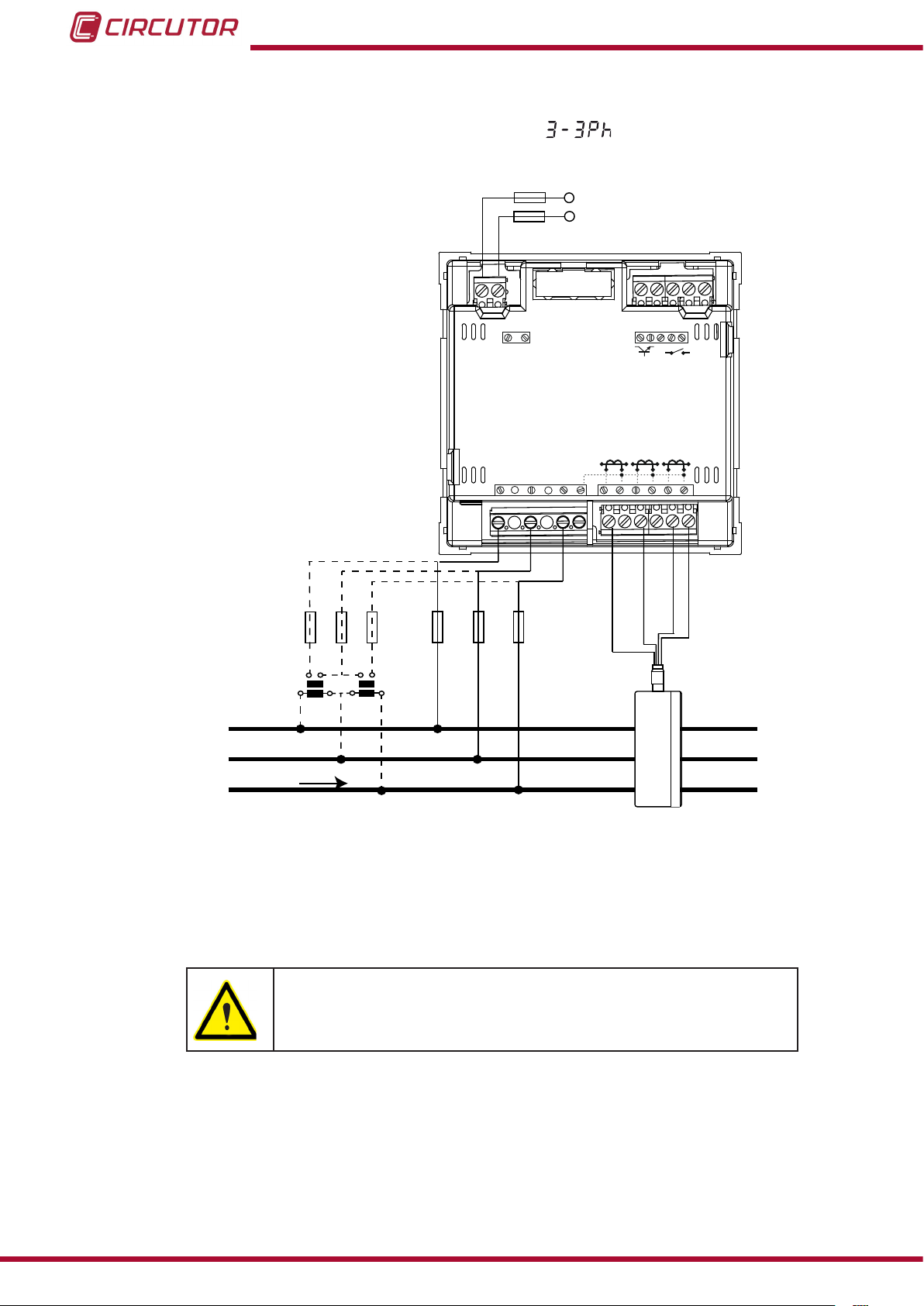
3�4�3�- Three-phase network measuring with a 3-wire connection, model CVM-C5-IC ����������������� 11
3�4�4�- Three-phase network measuring with a 3-wire connection, model CVM-C5-MC���������������12
3�4�5�- Three-phase network measuring with a 3-wire connection and transformers in an ARON
connection, models CVM-C5-IC and CVM-C5-MC� ���������������������������������������������������������������� 13
3�4�6�- Two-phase network measuring with a 3-wire connection, models CVM-C5-IC
and CVM-C5-MC �����������������������������������������������������������������������������������������������������������������������14
3�4�7�- Phase-to-phase single-phase network measuring with a 2-wire connection,
models CVM-C5-IC and CVM-C5-MC� ������������������������������������������������������������������������������������� 15
3�4�8�- Phase-to-neutral single-phase network measuring with a 2-wire connection ������������������� 16
4�- OPERATION �����������������������������������������������������������������������������������������������������������������������������������������������17
4�1�- MEASURING PARAMETERS ������������������������������������������������������������������������������������������������������������ 17
4�2�- KEYBOARD FUNCTIONS ������������������������������������������������������������������������������������������������������������������18
4�3�- DISPLAY ��������������������������������������������������������������������������������������������������������������������������������������������� 19
4�3�1� CONSUMPTION DATA AREA ���������������������������������������������������������������������������������������������������� 19
4�3�2� INSTANTANEOUS DATA AREA �������������������������������������������������������������������������������������������������22
4�4�-TARIFFS ���������������������������������������������������������������������������������������������������������������������������������������������� 24
4�5�- DIGITAL OUTPUT ������������������������������������������������������������������������������������������������������������������������������ 24
4�6�- PROGRAMMING �������������������������������������������������������������������������������������������������������������������������������� 24
4�6�1� Primary voltage �������������������������������������������������������������������������������������������������������������������������25
4�6�2� Secondary voltage ��������������������������������������������������������������������������������������������������������������������25
4�6�3� Primary current �������������������������������������������������������������������������������������������������������������������������26
4�6�4� Secondary current (only the model CVM-C5-IC) ���������������������������������������������������������������������� 26
4�6�5� Measurement system ����������������������������������������������������������������������������������������������������������������26
4�6�6� Ratio of kgC02 carbon emissions for Tariff 1 �������������������������������������������������������������������������� 27
4�6�7� Cost Ratio for Tariff 1 ���������������������������������������������������������������������������������������������������������������� 27
4�6�8� Ratio of kgCO2 carbon emissions for Tariff 2 ������������������������������������������������������������������������� 28
4�6�9� Cost Ratio for Tariff 2 ���������������������������������������������������������������������������������������������������������������� 28
4�6�10� Maximum demand variable ���������������������������������������������������������������������������������������������������� 29
4�6�11� Period of maximum demand integration �������������������������������������������������������������������������������29
4�6�12� Deleting maximum demand ���������������������������������������������������������������������������������������������������30
4�6�13� Default screen �������������������������������������������������������������������������������������������������������������������������30
4�6�14� Display backlight ���������������������������������������������������������������������������������������������������������������������30
4�6�15� Programming the digital output ��������������������������������������������������������������������������������������������31
4�6�16� Deleting energy meters ����������������������������������������������������������������������������������������������������������34
4�6�17� Deleting maximum and minimum values ������������������������������������������������������������������������������34
4�6�18� Locking the programming ������������������������������������������������������������������������������������������������������ 34
4�6�19� Password ���������������������������������������������������������������������������������������������������������������������������������35
5�- TECHNICAL FEATURES ����������������������������������������������������������������������������������������������������������������������������� 36
6�- MAINTENANCE AND TECHNICAL SERVICE �������������������������������������������������������������������������������������������� 38
7�- GUARANTEE �����������������������������������������������������������������������������������������������������������������������������������������������38
8�- CE CERTIFICATE ���������������������������������������������������������������������������������������������������������������������������������������� 39
4
Instruction Manual
Page 5

CVM-C5
REVISION LOG
Table 1: Revision log�
Date Revision Description
11/13 M98252801-03-13A Initial Version
6/14 M98252801-03-14A
6/14 M98252801-03-14B
Introduction model CVM-C5-MC
Modication section 4.6.4
Instruction Manual
5
Page 6
1�- VERIFICATION UPON RECEPTION
Check the following points when you receive the unit:
a) The unit meets the specications described in your order.
b) The unit has not suffered any damage during transport.
c) Perform an external visual inspection of the unit prior to switching it on.
d) Check that it has been delivered with the following:
- An installation guide,
- 2 Retainers for subsequent attachment of the unit
If any problem is noticed upon reception, immediately contact the transport
company and/or CIRCUTOR's after-sales service.
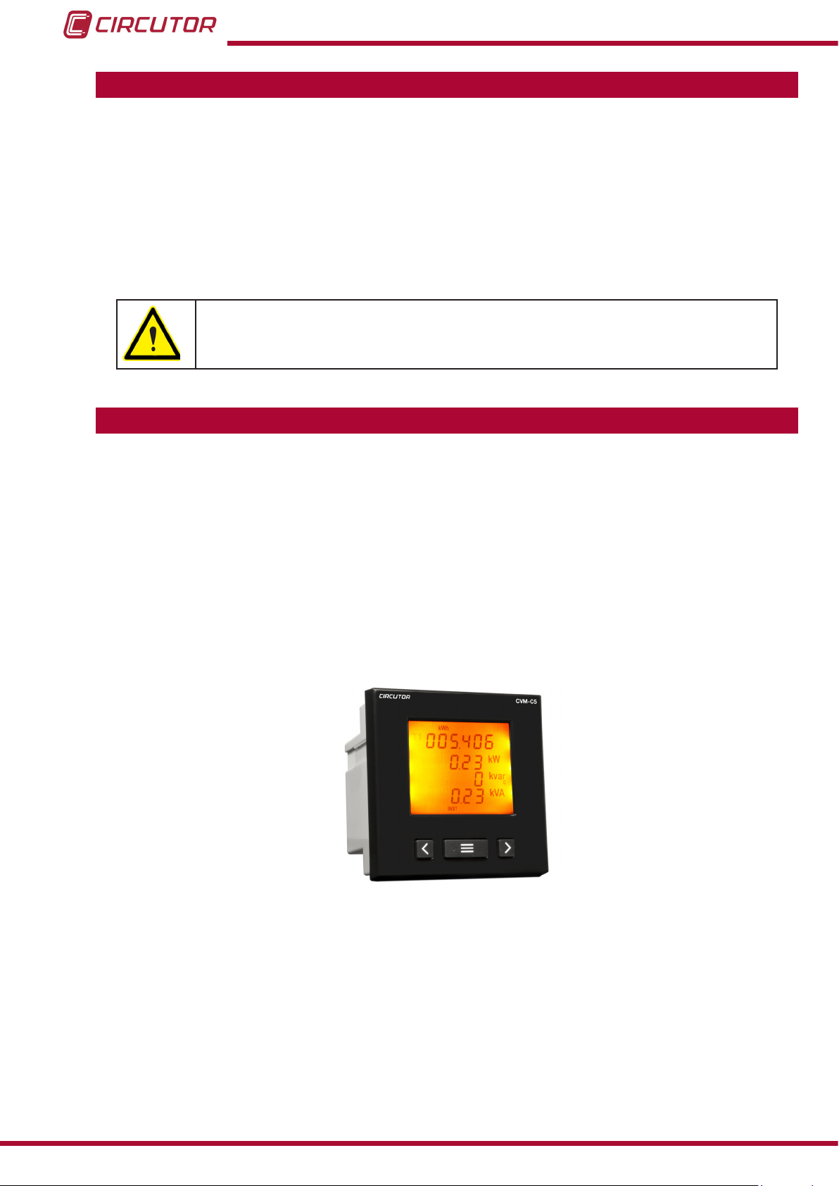
2�- PRODUCT DESCRIPTION
CVM-C5
The CVM-C5 unit measures, calculates and displays the main electrical parameters of the
following networks: single-phase, two-phase, with and without neutral, balanced three-phase,
with ARON measurements or unbalanced. The measurement will be taken in RMS with the
three AC voltage inputs and three current inputs.
There are 2 versions of the team based on the current input:
CVM-C5-IC, indirect mesure corrent with transformers /5A and /1A.
CVM-C5-MC, indirect measure current with efcient transformers series MC1 and
MC3.
The unit features:
- 3 keys that allow you to browse between the various screens and program the unit.
- LCD Display to display all the parameters,
- 1 digital input to select the tariff.
- 1 programmable digital output to act as a pulse or alarm output.
6
Instruction Manual
Page 7
CVM-C5
3�- UNIT INSTALLATION
3.1.- PRIOR RECOMMENDATIONS
In order to use the unit safely, it is critical that individuals who handle it follow
the safety measures described in the standards of the country where it is being
used, use the necessary personal protective equipment, and pay attention to
the various warnings indicated in this instruction manual.
The CVM-C5 unit must be installed by authorised and qualied staff.
The power supply plug must be disconnected and measuring systems switched off before
handling, altering the connections or replacing the unit. It is dangerous to handle the unit
while it is powered.
Also, it is critical to keep the cables in perfect condition in order to avoid accidents, personal
injury and damage to installations.
The manufacturer of the unit is not responsible for any damage resulting from failure by the
user or installer to heed the warnings and/or recommendations set out in this manual, nor for
damage resulting from the use of non-original products or accessories or those made by other
manufacturers.
In the event an anomaly or malfunction is detected in the unit, refrain from using it to take any
measurements.
Inspect the work area before taking any measurements. Do not take measurements in dangerous areas or where there is a risk of explosion.
Disconnect the unit from the power supply (unit and measuring system power
supply) before maintaining, repairing or handling the unit's connections.
Please contact the after-sales service if you suspect that there is an operational
fault in the unit.
3.2.- INSTALLATION
The unit will be installed on a panel (92
+0.8
x 92
+0.8
mm panel drill hole, in compliance with DIN
43700). All connections are located inside the electric panel.
Terminals, opening covers or removing elements can expose parts that are
hazardous to the touch while the unit is powered. Do not use the unit until it is
fully installed.
The unit must be connected to a power circuit that is protected with gl (IEC 269) or M type
fuses with a rating of 0.5 to 2 A. It must be tted with a circuit breaker or equivalent device,
in order to be able to disconnect the unit from the power supply network.
Instruction Manual
7
Page 8
CVM-C5
The power and voltage measuring circuit must be connected with cables that have a minimum cross-section of 1mm2.
The secondary line of the current transformer will have a minimum cross-section of 2.5
mm2.
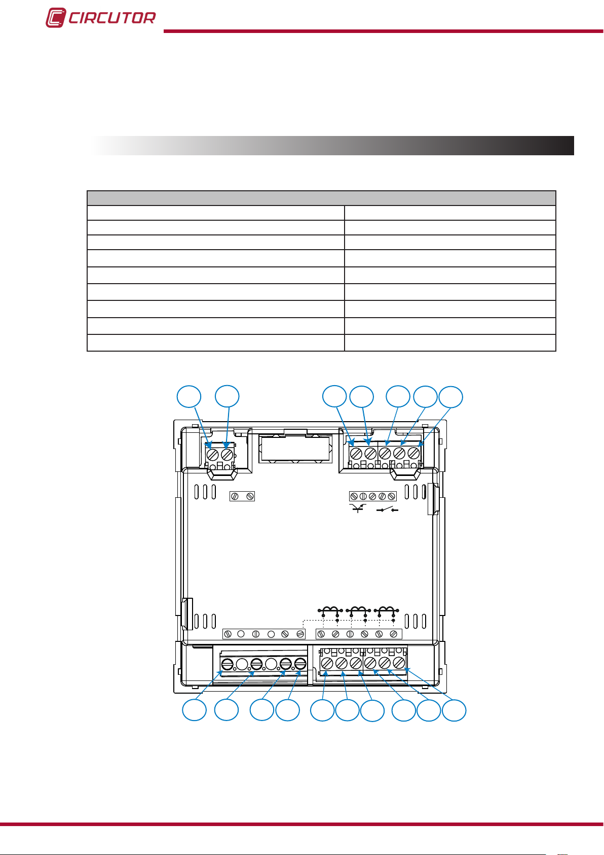
3.3.- UNIT TERMINALS
Table 2:List of CVM-C5 terminals�
Unit terminals
1 : Auxiliary Power Supply 10: VL3, L3 voltage input
2: Auxiliary Power Supply 11: N, neutral
3: SO+, Transistor output 12: S1, L1 current input
4: SO-, Transistor output 13: S2, L1 current input
5: Not connected 14: S2, L1 current input
6: Digital input 15: S2, L2 current input
7: Digital input 16: S1, L3 current input
8: VL1, L1 voltage input 17: S2, L3 current input
9: VL1, L1 voltage input
1
2
POWER SUPPLY
~
520V
V
V
L1
Ph-NPh-Ph
300V ~
L3L2
P1 P2
L1
NV
S1 S2 S1 S2 S1 S2
4
3
OUTPUT
S0+ S0-
P1 P2 P1 P2
L2 L3
INPUT
5
6 7
8
8
9 10 11 12 13
Figure 1: CVM-C5 terminals�
14
15
16 17
Instruction Manual
Page 9
CVM-C5
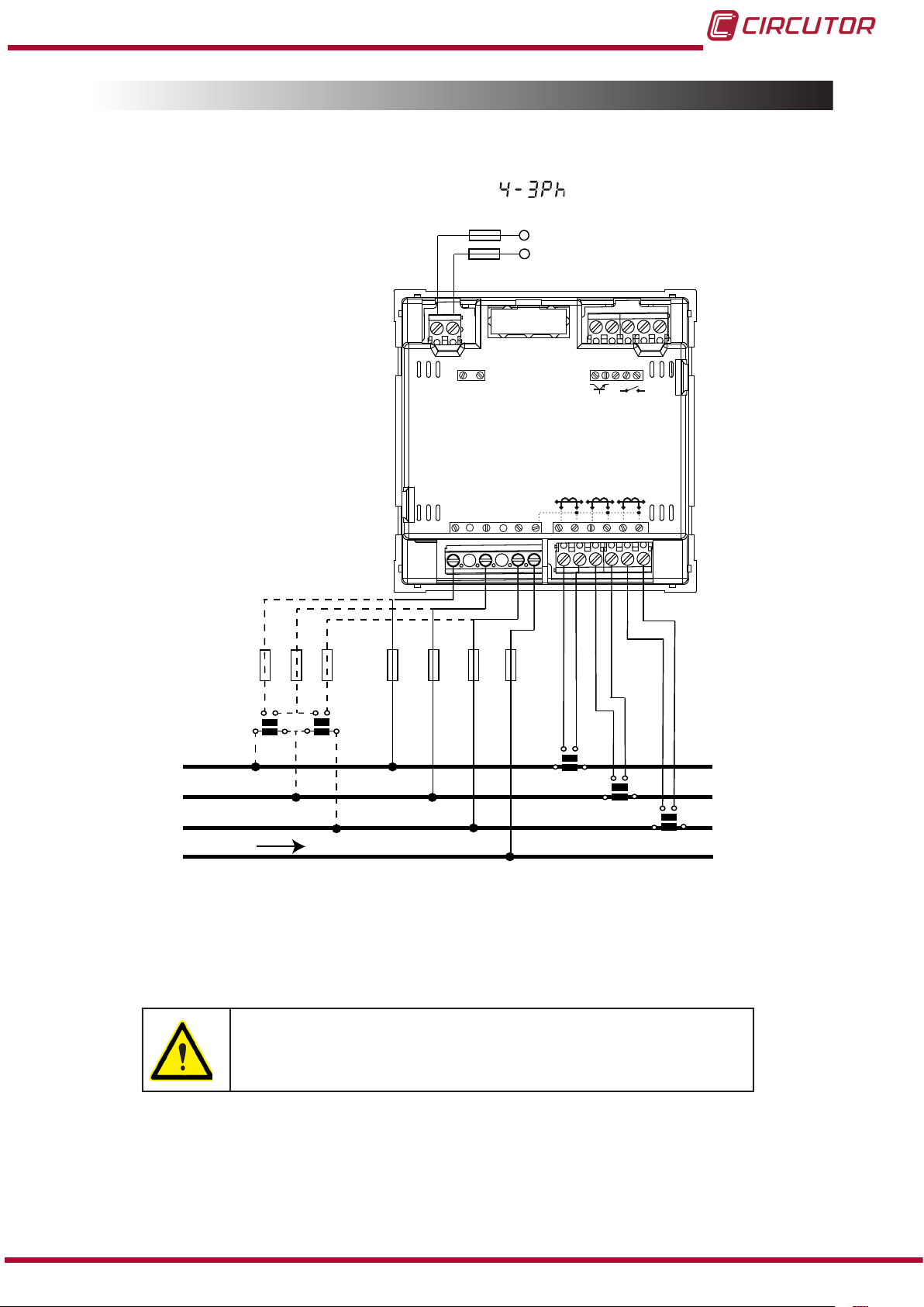
3.4.- CONNECTION DIAGRAMS
3�4�1�- Three-phase network measuring with a 4-wire connection, model CVM-C5-IC
Measurement system:
Power
Supply
OUTPUT
INPUT
POWER SUPPLY
S0+ S0-
Ph-NPh-Ph
P1 P2
300V ~
~
520V
V
V
L1
L3L2
NV
P1 P2 P1 P2
L1
L2 L3
S1 S2 S1 S2 S1 S2
VL1 VL2 VL3
VL1 VL2 VL3NN
b
a
A B
L1
L2
L3
a
A B
b
S1 S2
P2
P1
S1 S2
P1
P2
S1 S2
P1
LOAD
Figure 2:Three-phase measuring with a 4-wire connection, model CVM-C5-IC�
P2
Instruction Manual
Do not connect current transformers to earth
9
Page 10
CVM-C5
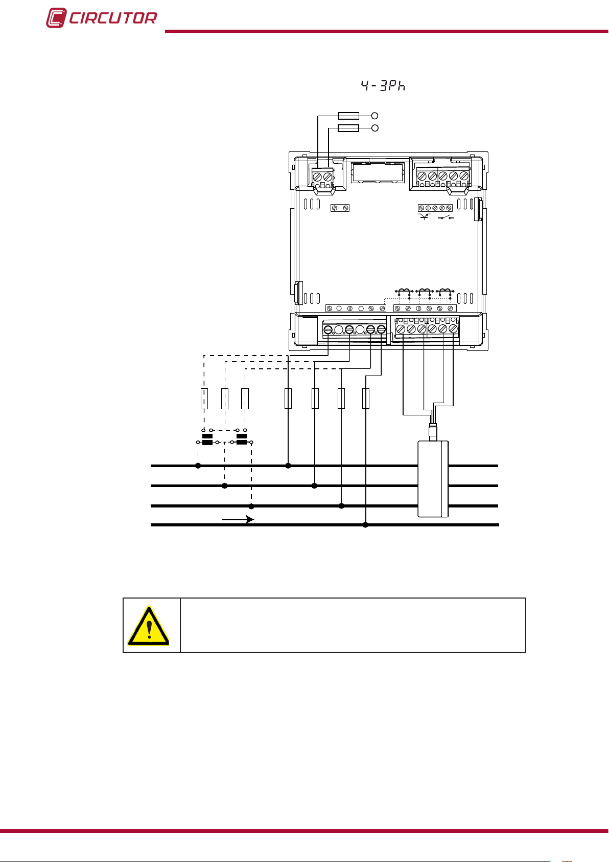
3�4�2�- Three-phase network measuring with a 4-wire connection, model CVM-C5-MC
Measurement system :
Power
Supply
OUTPUT
INPUT
POWER SUPPLY
~
520V
V
V
L1
Ph-NPh-Ph
300V ~
L3L2
NV
S0+ S0-
P1 P2
P1 P2 P1 P2
L1
L2 L3
S1 S2 S1 S2 S1 S2
VL1 VL2 VL3
Green/White
1P1
Red/Blue
Brown/Green
1P22P2
L1
b
a
A B
a
A B
VL1 VL2 VL3NN
Grey/Pink
b
L2
2P1
L3
3P1
3P2
LOAD
Figure 3: Three-phase measuring with a 4-wire connection, model CVM-C5-MC�
The value of the transformer secondary MC is xed at 0.250 A
10
Instruction Manual
Page 11
CVM-C5
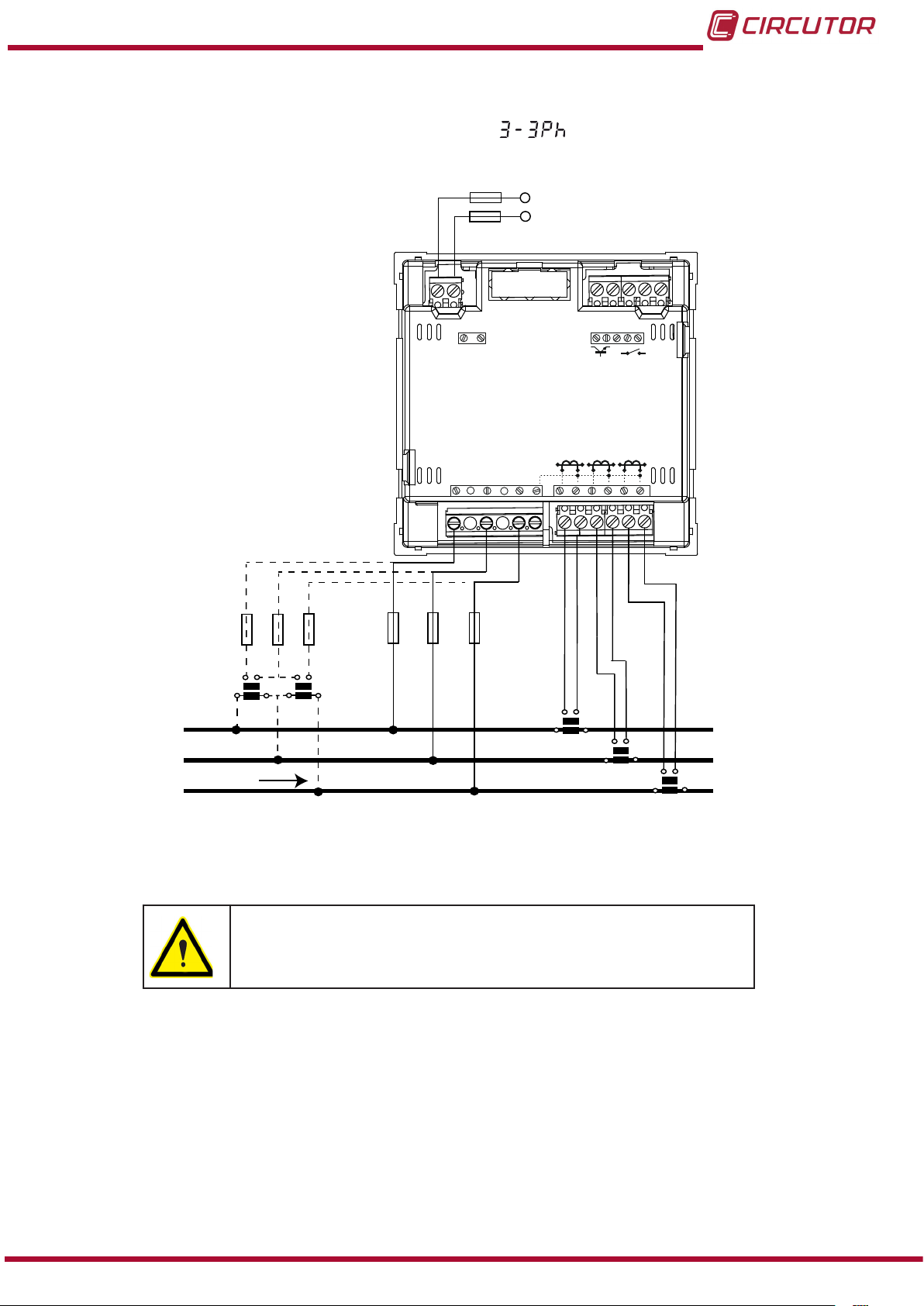
3�4�3�- Three-phase network measuring with a 3-wire connection, model CVM-C5-IC
Measurement system:
Power
Supply
OUTPUT
INPUT
POWER SUPPLY
~
520V
V
V
L1
Ph-NPh-Ph
300V ~
L3L2
NV
S0+ S0-
P1 P2
P1 P2 P1 P2
L1
L2 L3
S1 S2 S1 S2 S1 S2
L1
L2
L3
LOAD
VL1 VL2 VL3
b
a
A B
a
A B
b
VL1 VL2 VL3
S1 S2
P1
P2
S1 S2
P1
P2
S1 S2
P1
Figure 4: Three-phase measuring with a 3-wire connection, model CVM-C5-IC�
Do not connect current transformers to earth
P2
Instruction Manual
11
Page 12
CVM-C5
3�4�4�- Three-phase network measuring with a 3-wire connection , model CVM-C5-MC�
Measurement system:
Power
Supply
OUTPUT
INPUT
POWER SUPPLY
~
520V
V
V
L1
Ph-NPh-Ph
300V ~
L3L2
NV
S0+ S0-
P1 P2
P1 P2 P1 P2
L1
L2 L3
S1 S2 S1 S2 S1 S2
VL1 VL2 VL3
Green/White
1P1
Red/Blue
Brown/Green
1P22P2
L1
b
a
A B
a
A B
VL1 VL2 VL3
Grey/Pink
b
L2
2P1
L3
LOAD
3P1
3P2
Figure 5:Three-phase network measuring with a 3-wire connection, modelo CVM-C5-MC�
The value of the transformer secondary MC is xed at 0.250 A
12
Instruction Manual
Page 13

CVM-C5
3�4�5�- Three-phase network measuring with a 3-wire connection and transformers in an
ARON connection, models CVM-C5-IC and CVM-C5-MC�
Measurement system:
Power
Supply
OUTPUT
INPUT
POWER SUPPLY
~
520V
V
V
L1
Ph-NPh-Ph
300V ~
L3L2
NV
S0+ S0-
P1 P2
P1 P2 P1 P2
L1
L2 L3
S1 S2 S1 S2 S1 S2
VL1 VL2 VL3
a
A B
L1
b
a
A B
b
VL1 VL2 VL3
S1 S2
P1
P2
L2
L3
LOAD
S1 S2
Figure 6: Three-phase measuring with a 3-wire connection and transformers in an ARON connection, models CVM-
C5-IC and CVM-C5-MC
Model CVM-C5-MC:
The value of the transformer secondary MC is xed at 0.250 A.
Instruction Manual
13
Page 14

CVM-C5
3�4�6�- Two-phase network measuring with a 3-wire connection, models CVM-C5-IC and
CVM-C5-MC
Measurement system:
Power
Supply
OUTPUT
INPUT
POWER SUPPLY
~
520V
V
V
L1
Ph-NPh-Ph
300V ~
L3L2
NV
S0+ S0-
P1 P2
P1 P2 P1 P2
L1
S1 S2 S1 S2 S1 S2
L2 L3
L1
L2
VL1
a
A B
b
VL2N
a
b
A B
VL1
VL2
N
S1 S2
P2
P1
S1 S2
P1
P2
LOAD
N
Figure 7: Two-phase measuring with a 3-wire connection, models CVM-C5-IC and CVM-C5-MC�
Do not connect current transformers to earth
Model CVM-C5-MC:
The value of the transformer secondary MC is xed at 0.250 A.
14
Instruction Manual
Page 15

CVM-C5
3�4�7�- Phase-to-phase single-phase network measuring with a 2-wire connection, models CVM-C5-IC and CVM-C5-MC�
Measurement system:
Power
Supply
L1
L2
LOAD
VL1
POWER SUPPLY
~
520V
V
V
L1
VL2
Ph-NPh-Ph
300V ~
L3L2
P1 P2
L1
NV
S1 S2 S1 S2 S1 S2
S1 S2
P1
OUTPUT
S0+ S0-
P1 P2 P1 P2
INPUT
L2 L3
P2
Figure 8: Phase-to-phase single-phase measuring with a 2-wire connection, models CVM-C5-IC and CVM-C5-MC�
Do not connect current transformers to earth
Power supply should be referenced to the measurement system.
Model CVM-C5-MC:
The value of the transformer secondary MC is xed at 0.250 A.
Instruction Manual
15
Page 16

CVM-C5
3�4�8�- Phase-to-neutral single-phase network measuring with a 2-wire connection
Measurement system:
Power
Supply
OUTPUT
INPUT
POWER SUPPLY
S0+ S0-
L1
N
LOAD
VL1
a
A B
Ph-NPh-Ph
300V ~
~
520V
V
V
L1
VL1
N
b
L3L2
NV
S1 S2 S1 S2 S1 S2
P1
P1 P2
L1
S1 S2
P1 P2 P1 P2
L2 L3
P2
Figure 9: Phase-to-neutral single-phase measuring with a 2-wire connection�
Do not connect current transformers to earth
16
Model CVM-C5-MC:
The value of the transformer secondary MC is xed at 0.250 A.
Instruction Manual
Page 17

0º
90º
180º
-90º
Capacitive
Capacitive
Inductive
Inductive
Generation
Power
Consumption
Power
Single-phaseThree-phase
Single-phase
Single-phase
Single-phase
Three-phase
Three-phase
Three-phase
k
k
k
k
k
k
k
k
k
k
k
k
k
k
k
k
k
k
k
k
CVM-C5
4�- OPERATION
The CVM-C5 is a power analyzer in four quadrants (consumption and generation).
The unit displays the electrical parameters shown in Table 3.
Phase – neutral voltage Vph-n 9999 10.0
Phase-phase voltage Vph-ph 9999 10.0
Current A 9999 0.05
Frequency Hz 65 45
Active Power kW 9999 0.01
Inductive Reactive Power kvarL 9999 0.01
Capacitive Reactive Power kvarC 9999 0.01
Apparent Power kVA 9999 0.01
Power factor PF -0.99 0.99
Cos φ φ -0.99 0.99
Total Active Energy Consumed Tariff 1 kWh 999999 000.000
Total Active Energy Generated Tariff 1 kWh 999999 000.000
Inductive Reactive Energy Consumed Tariff 1 kvarLh 999999 000.000
Inductive Reactive Energy Generated Tariff 1 kvarLh 999999 000.000
Capacitive Reactive Energy Consumed Tariff 1 kvarch 999999 000.000
Capacitive Reactive Energy Generated Tariff 1 kvarch 999999 000.000
Total Apparent Energy Tariff 1 kVAh 999999 000.000
Total Active Energy Consumed Tariff 2 kWh 999999 000.000
Total Active Energy Generated Tariff 2 kWh 999999 000.000
Inductive Reactive Energy Consumed Tariff 2 kvarLh 999999 000.000
Inductive Reactive Energy Generated Tariff 2 kvarLh 999999 000.000
Capacitive Reactive Energy Consumed Tariff 2 kvarch 999999 000.000
Capacitive Reactive Energy Generated Tariff 2 kvarch 999999 000.000
Figure 10: Four quadrants of CVM-C5�
4.1.- MEASURING PARAMETERS
Table 3: CVM-5 measuring parameters�
Parameter Units
Maximum
value
Minimum
value
Instruction Manual
17
Page 18

CVM-C5
Parameter Units
Maximum
value
Minimum
value
Total Apparent Energy Tariff 2 kVAh 999999 000.000
No. of hours Tariff 1 hours 99999.9 00000.0
No. of hours Tariff 2 hours 99999.9 00000.0
Cost Tariff 1 COST 9999.99 0000.00
Cost Tariff 2 COST 9999.99 0000.00
CO2 Emissions Tariff 1 kgCO
CO2 Emissions Tariff 2 kgCO
2
2
9999.99 0000.00
9999.99 0000.00
Maximum Demand of Active power kW 9999 0.01
Maximum Demand of Apparent Power kVA 9999 0.01
Maximum Current Demand A 9999 0.05
4.2.- KEYBOARD FUNCTIONS
The CVM-C5 has 3 keys that allow you to browse between the various screens and program
the unit.
The rst keystroke on any of the keys after a period of inactivity switches on the backlight.
Key functions on measuring screens (Table 4):
Table 4: Key functions on measuring screens�
Key Short keystroke
Previous screen of the instant data area
Next screen of the instant
data area
Display of minimum value
Display of maximum value
Long keystroke
(2 s)
Browsing the different
screens of the consumption
Accessing the programming menu
data area
Display of the Maximum Demand
programmed and selected.
Key functions in the programming menu (Table 5):
Table 5: Key functions in the programming menu�
Key Keystroke
18
Moves an editable digit (ashing)
Increases the digits (0-9) or rotates between the different options.
Next page
Instruction Manual
Page 19

CVM-C5
4.3.- DISPLAY
The unit has a backlit LCD display showing all the parameters listed in Table 3.
The display is divided into two areas (Figure 11):
The consumption data area showing consumption parameters.
The instantaneous data area showing the maximum and minimum instantaneous
values being measured or calculated by the unit.
Figure 11: CVM-C5 display areas�
4�3�1� CONSUMPTION DATA AREA
The unit has 22 different screens in the consumption data area (Table 6).
Table 6: Consumption data area screens�
Screen Units
Total active energy generated Tariff 1
kWh
Inductive reactive energy generated Tariff 1
kvarLh
Capacitive reactive energy generated Tariff 1
kvarch
Instruction Manual
19
Page 20

Screen Units
Total apparent energy generated Tariff 1
CO2 Emissions Tariff 1
Cost Tariff 1
No. of hours Tariff 1
Total active energy consumed Tariff 1
kVAh
kgCO
COST
hours
CVM-C5
2
Inductive reactive energy consumed Tariff 1
Capacitive reactive energy consumed Tariff 1
Total apparent energy consumed Tariff 1
Total active energy generated Tariff 2
Inductive reactive energy generated Tariff 2
kWh
kvarLh
kvarch
kVAh
kWh
kvarLh
20
Capacitive reactive energy generated Tariff 2
kvarch
Total apparent energy generated Tariff 2
kVAh
Instruction Manual
Page 21

CVM-C5
Screen Units
CO2 Emissions Tariff 2
kgCO2
Cost Tariff 2
COST
No. of hours Tariff 2
hours
Total active energy consumed Tariff 2
kWh
Inductive reactive energy consumed Tariff 2
kvarLh
Capacitive reactive energy consumed Tariff 2
kvarch
Total apparent energy consumed Tariff 2
kVAh
With the key we can browse between the different screens.
The symbols T1 and T2 that appear on the display indicate the selected tariff and the tariff being
displayed, according to Table 9�
Instruction Manual
21
Page 22

CVM-C5
4�3�2� INSTANTANEOUS DATA AREA
To browse through the different screens that appear in the instantaneous data area, you have
to use the and keys.
This data area has 7 different screens, Table 7�
Table 7: CVM-C5 instantaneous data screens
Measurement
system
Screen Units
Phase-Phase Voltage
Current
Frequency
Phase-Neutral Voltage
Current
Frequency
Active power
Inductive Reactive Power
Apparent power
Active power
Capacitive Reactive Power
Apparent power
Vph-ph
A
Hz
Vph-n
A
Hz
kW
kvarL
kVA
kW
kvarC
kVA
22
Power factor
Cos φ
PF
φ
Instruction Manual
Page 23

CVM-C5
Also displayed on these screens are:
Maximum values
To see the maximum values of the screen being displayed, press the key for 2
seconds.
The MAX symbol appears on the display (Figure 12)
Figure 12: Instantaneous data screen displaying maximum values�
Minimum values
To see the minimum values of the screen being displayed, press the key for 2
seconds.
The MIN symbol appears on the display (Figure 13)
Figure 13: Instantaneous data screen displaying minimum values�
Maximum Demand
The unit can calculate the maximum demand of:
• Active Power,
• Apparent Power
• Current
Once the parameter to be integrated into the programming menu has been selected ( “4.6 .10.
Maximum demand variable”), you can display it on the display screen for the parameter by
pressing the and keys simultaneously.
The DEM symbol appears on the display (Figure 14)
Figure 14: Instantaneous data screen displaying the maximum demand value�
Instruction Manual
23
Page 24

CVM-C5
4.4.- TARIFFS
The CVM-C5 has two tariffs, T1 and T2, which can be selected through a digital input.
The selected tariff is determined based on the status of the input, as shown in Table 8.
Table 8: Tariff selection�
Tariff Digital input
T1 0
T2 1
The symbols T1 and T2 that appear on the display in the consumption data area indicate the
selected tariff and the tariff being shown according to Table 9�
Table 9: Displaying tariffs on the display�
Symbol Display Selected tariff
T1 ashing Tariff 1 Tariff 1
T1 ashing
T2 steady
T1 ashing Tariff 2 Tariff 2
T2 ashing
T1 steady
Tariff 2 Tariff 1
Tariff 1 Tariff 2
4.5.- DIGITAL OUTPUT
The unit has an optoisolated NPN transistor (terminals 3 and 4 of Figure 1) that may be programmed as:
A pulse output by kWh or kvarh�
An alarm associated with a measurement parameter.
4.6.- PROGRAMMING
From the programming menu you can:
Dene the transformation ratios.
Program the ratio of kgCO2 carbon emissions of the two tariffs.
Program the cost ratio of the two tariffs.
Program the maximum demand parameters.
Delete the energy meters and the maximum and minimum values.
Modify the display's backlight.
Program the digital output.
The CVM-C5 does not record programming changes until the programming is complete. If
the unit is RESET before nishing the programming or no key is pressed for 30 seconds, the
conguration will not be stored in the memory.
24
The CVM-C5 does not take any measurements during programming.
To enter the programming menu press the key for 3 seconds.
And press to access the rst programming point.
Instruction Manual
Page 25

CVM-C5
4�6�1� Primary voltage
On this screen the voltage transformer primary is programmed.
To enter or modify the transformer primary value, press the
key repeatedly, increasing the value of the ashing digit.
When the on-screen value is that desired, press the
key to
go to the next digit to modify the other values.
If you press the key after changing the last digit, it will jump back to the rst digit so you
can modify the previously programmed values again.
To validate the information and go to the next programming step, press .
If the value entered is greater than the maximum programming value, the digits ash for 2
seconds and the programmed value is deleted.
Maximum programming value: 99999.
Minimum programming value: 0.
4�6�2� Secondary voltage
On this screen the voltage transformer secondary is programmed.
To enter or modify the voltage transformer secondary value, press
the
key repeatedly, increasing the value of the ashing digit.
When the on-screen value is that desired, press the key to go to the next digit and modify
the other values.
If you press the key after changing the last digit, it will jump back to the rst digit so you
can modify the previously programmed values again.
To validate the information and go to the next programming step, press .
If the value entered is greater than the maximum programming value, the digits ash for 2
seconds and the programmed value is deleted.
Maximum programming value: 999.
Minimum programming value: 0.
Instruction Manual
25
Page 26

4�6�3� Primary current
CVM-C5
On this screen the current transformer primary is programmed.
To enter or modify the transformer primary value, press the
key repeatedly, increasing the value of the ashing digit.
When the on-screen value is that desired, press the
go to the next digit to modify the other values.
key to
If you press the key after changing the last digit, it will jump back to the rst digit so you
can modify the previously programmed values again.
To validate the information and go to the next programming step, press .
If the value entered is greater than the maximum programming value, the digits ash for 2
seconds and the programmed value is deleted.
Maximum programming value: 9999.
Minimum programming value: 0.
4�6�4� Secondary current (only the model CVM-C5-IC)
On this screen the current transformer secondary is selected.
Use the
key to jump between the two possible options for
the current transformer secondary (1 A or 5 A).
To validate the information and go to the next programming step, press .
Note: If the voltage ratio together with the programmed current ratio exceeds the maximum
power value that can be measured by the unit, it will return to the primary voltage programming
step when you press the key.
Nota : To apply the change to the second current transformer is necessary to reset the computer.
4�6�5� Measurement system
On this screen the measurement system to be used in the
installation is selected.
The
key jumps between the different options
26
Instruction Manual
Page 27

CVM-C5
Three-phase network measuring with a 4-wire connection.
Three-phase network measuring with a 3-wire connection.
Three-phase network measuring with a 3-wire connection and transformers in an
ARON connection .
Two-phase network measuring with a 3-wire connection.
Phase-to-phase single-phase network measuring with a 2-wire connection.
Phase-to-neutral single-phase network measuring with a 2-wire connection.
To validate the information and go to the next programming step, press .
4�6�6� Ratio of kgC02 carbon emissions for Tariff 1
The carbon emissions ratio is the amount of emissions released
into the atmosphere to produce a unit of electricity (1 kWh).
The ratio for the European mix is approximately 0.65 kgCO2 per
kWh.
To enter or modify the emissions ratio value, press the
key
repeatedly, increasing the value of the ashing digit.
When the on-screen value is that desired, press the key to go to the next digit to modify
the other values.
If you press the key after changing the last digit, it will jump back to the rst digit so you
can modify the previously programmed values again.
To validate the information and go to the next programming step, press .
If the value entered is greater than the maximum programming value, the digits ash for 2
seconds and the programmed value is deleted.
Maximum programming value: 9.999.
Minimum programming value: 0.
4�6�7� Cost Ratio for Tariff 1
On this screen the cost per kWh of electricity of Tariff 1 is
programmed.
To enter or modify the cost ratio value, press the
key
repeatedly, increasing the value of the ashing digit.
When the on-screen value is that desired, press the
key to
go to the next digit to modify the other values.
If you press the key after changing the last digit, it will jump back to the rst digit so you
can modify the previously programmed values again.
Instruction Manual
27
Page 28

CVM-C5
To validate the information and go to the next programming step, press .
If the value entered is greater than the maximum programming value, the digits ash for 2
seconds and the programmed value is deleted.
Maximum programming value: 9.999.
Minimum programming value: 0.
4�6�8� Ratio of kgCO2 carbon emissions for Tariff 2
The carbon emissions ratio is the amount of emissions released
into the atmosphere to produce a unit of electricity (1kWh).
The ratio for the European mix is approximately 0.65 kgCO2 per
kWh.
To enter or modify the emissions ratio value, press the
key
repeatedly, increasing the value of the ashing digit.
When the on-screen value is that desired, press the key to go to the next digit
to modify the other values.
If you press the key after changing the last digit, it will jump back to the rst digit so you
can modify the previously programmed values again.
To validate the information and go to the next programming step, press .
If the value entered is greater than the maximum programming value, the digits ash for 2
seconds and the programmed value is deleted.
Maximum programming value: 9.999.
Minimum programming value: 0.
4�6�9� Cost Ratio for Tariff 2
28
On this screen the cost per kWh of electricity of Tariff 2 is
programmed.
To enter or modify the primary cost ratio value, press the
key
repeatedly, increasing the value of the ashing digit.
When the on-screen value is that desired, press the
key to
go to the next digit to modify the other values.
If you press the key after changing the last digit, it will jump back to the rst digit so you
can modify the previously programmed values again.
To validate the information and go to the next programming step, press .
Instruction Manual
Page 29

CVM-C5
If the value entered is greater than the maximum programming value, the digits ash for 2
seconds and the programmed value is deleted.
Maximum programming value: 9.999.
Minimum programming value: 0.
4�6�10� Maximum demand variable
On this screen the variables to integrate into the Maximum
Demand concept are selected.
The display shows the digits that identify that code for the
variable to be integrated according to Table 10
Table 10: Codes for maximum demand variables
Parameter Code
Active three-phase power 16
Apparent three-phase power 34
Three-phase current 36
None 00
The key jumps between the different options.
To validate the information and go to the next programming step, press .
4�6�11� Period of maximum demand integration
On this screen the maximum demand integration period is
programmed.
To enter or modify the integration period value, press the
key
repeatedly, increasing the value of the ashing digit.
When the on-screen value is that desired, press the
key to
go to the next digit to modify the other values.
If you press the key after changing the last digit, it will jump back to the rst digit so you
can modify the previously programmed values again.
The integration period may range from 1 to 60 minutes.
To validate the information and go to the next programming step, press .
If the value entered is greater than the maximum programming value, the digits ash for 2
seconds and the programmed value is deleted.
Instruction Manual
29
Page 30

4�6�12� Deleting maximum demand
On this screen you select whether or not to delete the maximum
demand.
CVM-C5
Use the
key to jump between the two options (Yes and No).
To validate the information and go to the next programming step,
press
.
4�6�13� Default screen
On this screen the default or start-up instantaneous data screen
(Table 7) for the CVM-C5 is selected.
Press the
key repeatedly until you see the default screen of
your choice.
To validate the screen and go to the next programming step,
press
.
The electrical parameters may also be displayed by automatically rotating through the 7
instantaneous data screens in 5-second intervals.
To do so press the key repeatedly until the parameters ash;
To validate the rotating screen function and go to the next programming step, press .
4�6�14� Display backlight
On this screen the time that the Backlight will stay lit (in seconds)
after the last keystroke on the unit is programmed.
To enter or modify the backlight value, press the
key
repeatedly, increasing the value of the ashing digit.
When the on-screen value is that desired, press the key to go to the next digit to modify
the other values.
The value 00 indicates that the backlight will stay permanently lit.
The backlight time may range from 5 to 99 seconds.
To validate the information and go to the next programming step, press .
30
Instruction Manual
Page 31

CVM-C5
4�6�15� Programming the digital output
The CVM-C5 digital output may be programmed as:
Pulse by n kWh or kvarh (Energy): the value corresponding to the energy consumed
or generated may be programmed, to generate a pulse.
Alarm condition: a magnitude may be associated with the digital output, setting a
maximum, minimum and delay value for the trip condition.
If you do not wish to program a variable, put 00 and validate with the key.
Pulse programming by n kWh or kvarh
On this screen the energy code is selected based on Table 11 for
the energy you want the pulse output to generate.
The
key jumps between the different options.
Table 11: Codes for the different energy types�
Parameter Code
Active Energy III Tariff 1 31
Inductive Reactive Energy III Tariff 1 32
Capacitive Reactive Energy III Tariff 1 33
Apparent Energy III Tariff 1 48
Active Energy III Generated Tariff 1 49
Inductive Reactive Energy III Generated Tariff 1 50
Capacitive Reactive Energy III Generated Tariff 1 51
Apparent Energy III Generated Tariff 1 52
Active Energy III Tariff 2 55
Inductive Reactive Energy III Tariff 2 56
Capacitive Reactive Energy III Tariff 2 57
Apparent Energy III Tariff 2 58
Active Energy III Generated Tariff 2 59
Inductive Reactive Energy III Generated Tariff 2 60
Capacitive Reactive Energy III Generated Tariff 2 61
Apparent Energy III Generated Tariff 2 62
Active Energy Consumed
(Regardless of the tariff selected)
99
When an energy variable is programmed for the pulse output, the unit will initially give the
pulses corresponding to the energy accumulated so far.
Once an Energy code has been selected and validated using the key you must enter the
kilowatts per pulse.
Instruction Manual
31
Page 32

CVM-C5
To enter or modify the kilowatts per pulse value, press the
key repeatedly, increasing the value of the ashing digit.
When the on-screen value is that desired, press the
key to
go to the next digit to modify the other values.
If you press the key after changing the last digit, it will jump back to the rst digit so you
can modify the previously programmed values again.
Example: To program 500 Wh per pulse: 000.500
To program 1.5 kWh per pulse: 001.500
Once the desired option has been programmed, press the key to validate the information
and thereby nish programming the unit.
Maximum programming value: 999999 KWh.
Minimum programming value: 000.001 KWh.
Programming by alarm condition
On this screen the parameter code for which you want an alarm
to be generated is selected, based on Table 12�
The key jumps between the different options.
Table 12: Parameter codes for alarm programming�
Parameter Code Parameter Code
Active power III 16 Line voltage III 45
III Inductive Power 17 Apparent power III 34
III Capacitive Power 18 Maximum Demand 35
Three-phase Cosine φ 19 Current III 36
Power factor III 20 Phase voltage III 44
Frequency 21
Once an alarm code has been selected and validated with the key you must enter the
maximum value of the alarm condition.
32
Instruction Manual
Page 33

CVM-C5
The maximum value: above this value the transistor is closed.
To enter or modify the maximum value, press the
key
repeatedly, increasing the value of the ashing digit.
When the on-screen value is that desired, press the
key to
go to the next digit to modify the other values.
If you press the key after modifying the last digit the decimal point position will be
programmed.
To validate the information and proceed to programming the minimum value, press .
The minimum value: below this value the transistor is closed.
To enter or modify the minimum value, press the
key
repeatedly, increasing the value of the ashing digit.
When the on-screen value is that desired, press the
key to
go to the next digit to modify the other values.
If you press the key after modifying the last digit the decimal point position will be
programmed.
To validate the information and proceed to programming the delay value, press .
This is where the device's connection and disconnection delay (in
seconds) are programmed.
To enter or modify the delay value, press the
key repeatedly,
increasing the value of the ashing digit.
When the on-screen value is that desired, press the
key to
go to the next digit to modify the other values.
Once the delay has been programmed, press the key to go to the next programming step.
In Table 13 we can see the functioning of the digital output based on the programmed maxi-
mum and minimum values.
Instruction Manual
33
Page 34

CVM-C5
Table 13: Functioning of the digital output based on the programmed maximum and minimum values�
Minimum value Maximum
value�
Positive Positive MAX > MIN
Positive Positive MAX < MIN
Negative Positive
Positive Negative
Condition Digital output functioning
Negative Negative MAX > MIN
Negative Negative MAX < MIN
4�6�16� Deleting energy meters
On this screen you select whether or not to delete the energy
meters.
Use the
key to jump between the two options (Yes and No).
To validate the information and go to the next programming step,
press
.
4�6�17� Deleting maximum and minimum values
34
On this screen you select whether or not to delete the maximum
and minimum values
Use the
key to jump between the two options (Yes and No).
To validate the information and go to the next programming step,
press
.
Instruction Manual
Page 35

CVM-C5
4�6�18� Locking the programming
This screen is for protecting the data configured in the
programming menu.
Use the
key to jump between the two options:
When you enter the programming menu you can view and modify the programming.
When you enter the programming you can view the programming but not modify it. . In order
to modify the programming you need to enter a password.
To validate the information and go to the next programming step, press .
4�6�19� Password
On this screen the password to modify the programming
parameters is programmed.
To enter or modify the value, press the
key repeatedly,
increasing the value of the ashing digit.
When the on-screen value is that desired, press the key to go to the next digit to modify
the other values.
Default value: 1234.
Press the key to nish programming the unit.
Instruction Manual
35
Page 36

5�- TECHNICAL FEATURES
AC Power supply
Rated voltage 85 ... 265 V~
Frequency 50 ... 60 Hz
Consumption 3.5... 6 VA
Installation category CAT III 300V
DC Power supply
CVM-C5
Rated voltage
Consumption 2 ... 6W
Installation category CAT III 300V
Voltage measurement circuit
Nominal voltage (Un) 300V P-N, 520V P-P
Voltage measurement margin 5 ... 120% Un
Frequency measurement margin 45 ... 65Hz
Input impedance 440 kΩ
Min� voltage measurement (Vstart) 10V P-N
Installation category CAT III 300V
Current measurement circuit
Model CVM-C5-IC CVM-C5-MC
Nominal current (ln) .../5A o .../1A .../0250A
Current measurement margin 5 ... 110% ln 5 ... 110% ln
Maximum current, impulse < 1s 100 A 100 A
Minimum current measurement (Istart) 10 mA
Installation Category CAT III 300V CAT III 300V
95 ... 300 V
MC1 MC3
0.25 A 0.12 A
Measurement accuracy
Model CVM-C5-IC CVM-C5-MC
Voltage measurement 0.5% 0.5%
Current measurement 0.5% ± 1 digit 0.5% ± 1 digit
Power measurement 1% ± 1 digit 1% ± 1 digit
Active energy measurement Class 1 Class 1
Reactive energy measurement Class 1 Class 1
Pulse output
Type NPN
Maximum voltage
Maximum current 50 mA
Maximum frequency 5 pulses / sec
Minimum pulse width 100 ms (Ton: 100 ms, Toff: 100 ms)
Digital input
Type Potential free contact
Insulation Optoisolated
24 V
36
Instruction Manual
Page 37

CVM-C5
User interface
Display LCD (60x54mm)
Keyboard 3 keys
Environmental features
Operating temperature -5ºC... +45ºC
Storage temperature -10ºC ... +50ºC
Relative humidity (non-condensing) 5 ... 95%
Maximum altitude 2000 m
Protection degree IP31
Front panel: IP51
Mechanical features
Dimensions ( Figure 15) 96.7x96.7x62.6 mm
Weight 480 gr
Enclosure V0 self-extinguishing plastic
Attachment Panel
2.7
9.9
62.6
50
91.8
96.7
96.7
Figure 15:Dimensions�
Standards
Safety of electronic measuring units IEC 61010: 2010
Electromagnetic compatibility (CEM)� Part 6-4: Generic
UNE-EN 61000-6-4:2007
standards� Emissions standard for industrial environments�
Electromagnetic compatibility (CEM)� Part 6-2: Generic
UNE-EN 61000-6-2:2006
standards� Immunity for industrial environments�
Instruction Manual
37
Page 38

6�- MAINTENANCE AND TECHNICAL SERVICE
In the case of any query in relation to unit operation or malfunction, please contact the
CIRCUTOR, SA Technical Support Service.
Technical Assistance Service
Vial Sant Jordi, s/n, 08232 - Viladecavalls (Barcelona)
Tel: 902 449 459 ( España) / +34 937 452 919 (outside of Spain)
email: sat@circutor.es
7�- GUARANTEE
CVM-C5
CIRCUTOR guarantees its products against any manufacturing defect for two years after the
delivery of the units.
CIRCUTOR will repair or replace any defective factory product returned during the guarantee
period.
• No returns will be accepted and no unit will be repaired or replaced if it is not accompanied by a report indicating the defect detected or the reason for the return.
•The guarantee will be void if the units has been improperly used or the storage, installation and maintenance instructions listed in this manual have not been
followed. “Improper usage” is de ned as any operating or storage condition contrary to the national electrical code or that surpasses the limits indicated in the
technical and environmental features of this manual.
• CIRCUTOR accepts no liability due to the possible damage to the unit or other
parts of the installation, nor will it cover any possible sanctions derived from a possible failure, improper installation or “improper usage” of the unit. Consequently,
this guarantee does not apply to failures occurring in the following cases:
- Overvoltages and/or electrical disturbances in the supply;
- Water, if the product does not have the appropriate IP classi cation;
- Poor ventilation and/or excessive temperatures;
- Improper installation and/or lack of maintenance;
- Buyer repairs or modi cations without the manufacturer’s authorisation.
38
Instruction Manual
Page 39

CVM-C5
8�- CE CERTIFICATE
Instruction Manual
39
Page 40

CIRCUTOR, SA
Vial Sant Jordi, s/n
08232 -Viladecavalls (Barcelona)
Tel.: (+34) 93 745 29 00 - Fax: (+34) 93 745 29 14
www.circutor.es central@circutor.es
 Loading...