

Page 1
Power analyzer
CVM-C10
INSTRUCTION MANUAL
(M001B01-03-15A)
Page 2

CVM-C10
2
Instruction Manual
Page 3
CVM-C10
SAFETY PRECAUTIONS
Follow the warnings described in this manual with the symbols shown below.
DANGER
Warns of a risk, which could result in personal injury or material damage.
ATTENTION
Indicates that special attention should be paid to a speci c point.
If you must handle the unit for its installation, start-up or maintenance, the following
should be taken into consideration:
Incorrect handling or installation of the unit may result in injury to personnel as well as damage
to the unit. In particular, handling with voltages applied may result in electric shock, which may
cause death or serious injury to personnel. Defective installation or maintenance may also
lead to the risk of re.
Read the manual carefully prior to connecting the unit. Follow all installation and maintenance
instructions throughout the unit’s working life. Pay special attention to the installation standards of the National Electrical Code.
Refer to the instruction manual before using the unit
In this manual, if the instructions marked with this symbol are not respected or carried out correctly, it can
result in injury or damage to the unit and /or installations.
CIRCUTOR, SA reserves the right to modify features or the product manual without prior noti cation.
DISCLAIMER
CIRCUTOR, SA reserves the right to make modi cations to the device or the unit speci ca-
tions set out in this instruction manual without prior notice.
CIRCUTOR, SA on its web site, supplies its customers with the latest versions of the device
speci cations and the most updated manuals.
www.circutor.com
Instruction Manual
3
Page 4

CVM-C10
CONTENTS
SAFETY PRECAUTIONS ���������������������������������������������������������������������������������������������������������������������������������������3
DISCLAIMER ����������������������������������������������������������������������������������������������������������������������������������������������������������3
CONTENTS ������������������������������������������������������������������������������������������������������������������������������������������������������������� 4
REVISION LOG �������������������������������������������������������������������������������������������������������������������������������������������������������6
1�- VERIFICATION UPON RECEPTION ����������������������������������������������������������������������������������������������������������������� 7
2�- PRODUCT DESCRIPTION �������������������������������������������������������������������������������������������������������������������������������� 7
3�- UNIT INSTALLATION ���������������������������������������������������������������������������������������������������������������������������������������� 8
3�1�- PRIOR RECOMMENDATIONS�������������������������������������������������������������������������������������������������������������������8
3�2�- INSTALLATION ������������������������������������������������������������������������������������������������������������������������������������������9
3�3�- UNIT TERMINALS ������������������������������������������������������������������������������������������������������������������������������������ 10
3�3�1�- List of terminals, CVM-C10-ITF, CVM-C10-MC and CVM-C10-mV models ��������������������������������10
3�3�2�- List of terminals, CVM-C10-ITF-IN models� ��������������������������������������������������������������������������������� 11
3�4�- CONNECTION DIAGRAM ����������������������������������������������������������������������������������������������������������������������� 12
3�4�1�- Measuring Three-Phase Networks with a 4-wire connection, CVM-C10-ITF and ��������������������� 12
CVM-C10-mV model� ��������������������������������������������������������������������������������������������������������������������������������� 12
3�4�2�- Measuring Three-Phase Networks with a 4-wire connection, CVM-C10-ITF-IN model� ����������� 13
3�4�3�- Measuring Three-Phase Networks with a 4-wire connection, CVM-C10-MC model� ��������������� 14
3�4�4�- Measuring Three-Phase Networks with a 3-wire connection, CVM-C10-ITF and ��������������������� 15
CVM-C10-mV model� ������������������������������������������������������������������������������������������������������������������������������� 15
3�4�5�- Measuring Three-Phase Networks with a 3-wire connection, CVM-C10-MC model� �������������� 16
3�4�6�- Measuring Three-Phase Networks with a 3-wire connection and transformers with an
ARON connection, CVM-C10-ITF, CVM-C10-MC and CVM-C10-mV models� ��������������������������������������17
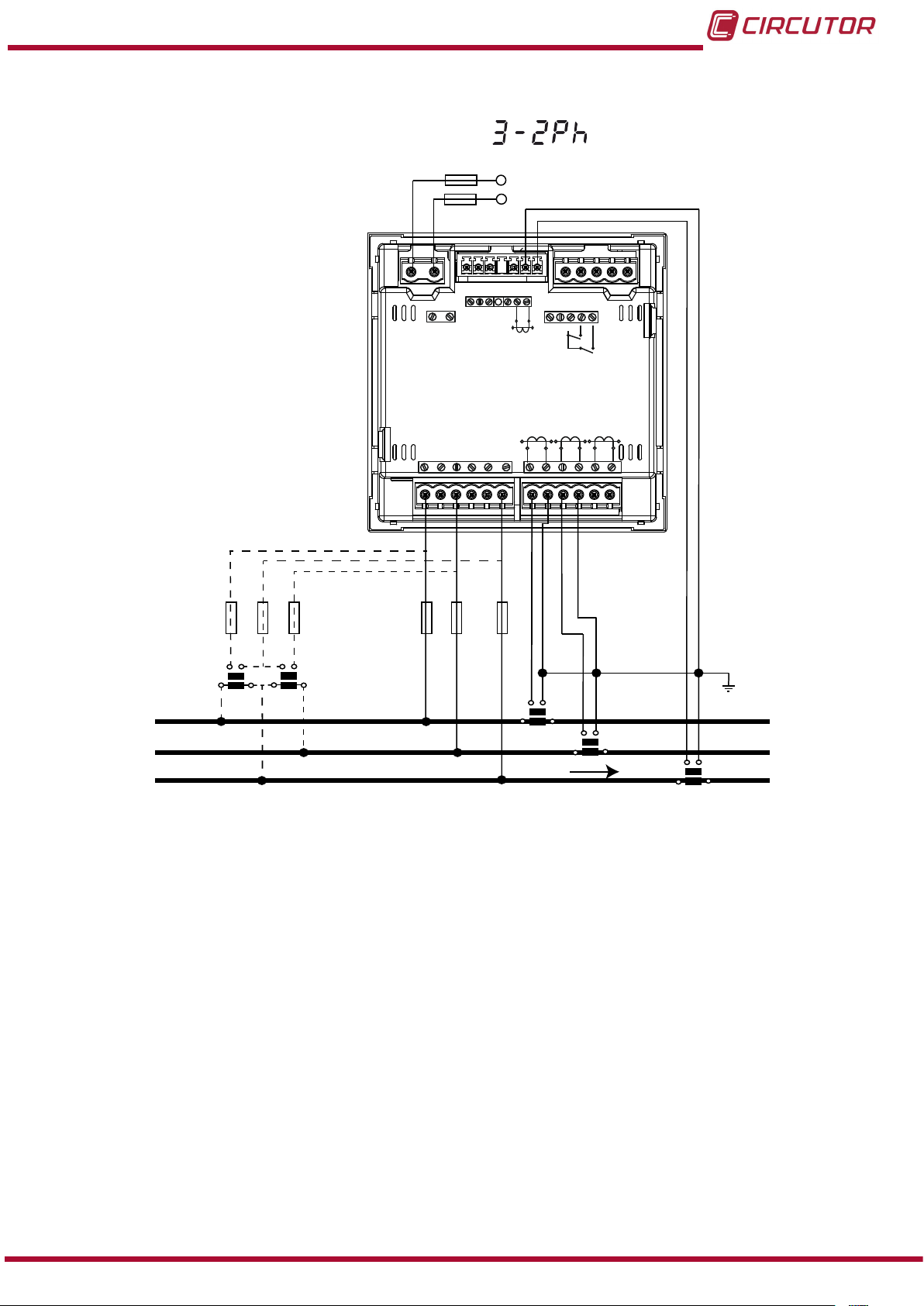
3�4�7�- Measuring Two-Phase Networks with a 3-wire connection, CVM-C10-ITF, CVM-C10-MC and
CVM-C10-mV models� ������������������������������������������������������������������������������������������������������������������������������ 18
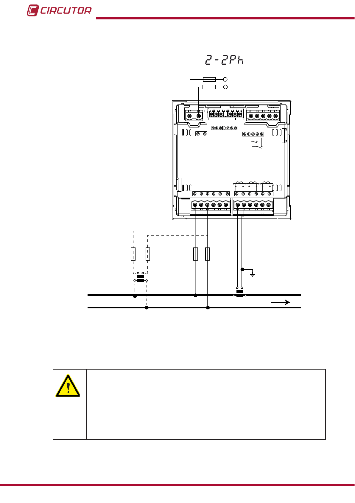
3�4�8�- Measuring Two-Phase Networks with a 3-wire connection, CVM-C10-ITF-IN model� ��������������19
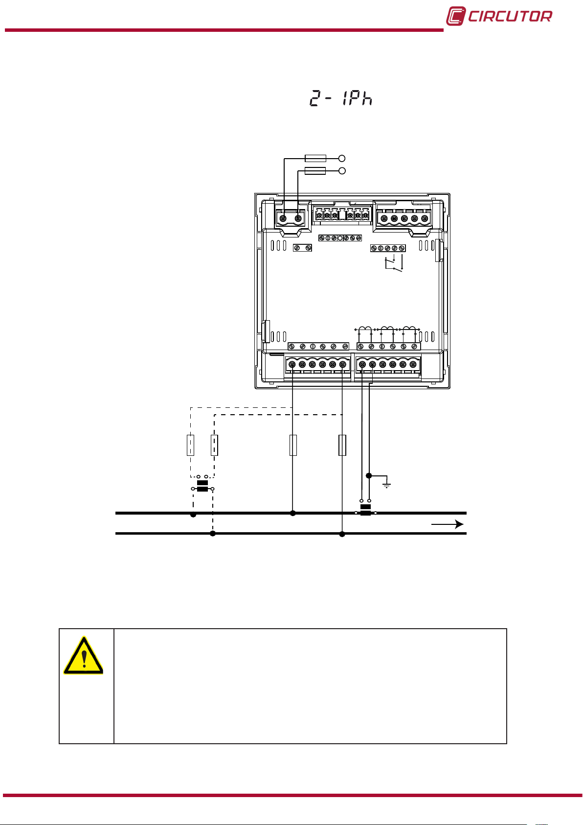
3�4�9�- Measuring Single-Phase Networks, phase to phase, with a 2-wire connection, CVM-C10-ITF,
CVM-C10-MC and CVM-C10-mV models� ��������������������������������������������������������������������������������������������� 20
3�4�10�- Measuring Single-Phase Networks, phase to neutral, with a 2-wire connection,
CVM-C10-ITF, CVM-C10-MC and CVM-C10-mV models� �����������������������������������������������������������������������21
4�- OPERATION ����������������������������������������������������������������������������������������������������������������������������������������������������22
4�1�- MEASURING PARAMETERS ������������������������������������������������������������������������������������������������������������������22
4�2�- KEYBOARD FUNCTIONS ������������������������������������������������������������������������������������������������������������������������23
4�3�- DISPLAY ���������������������������������������������������������������������������������������������������������������������������������������������������25
4.3.1. COS φ - PF (POWER FACTOR) BAR ����������������������������������������������������������������������������������������������25
4�3�2� ANALOGUE BAR ����������������������������������������������������������������������������������������������������������������������������� 26
4�3�3� OTHER SYMBOLS ON THE DISPLAY ��������������������������������������������������������������������������������������������26
4�4�- LED INDICATORS ������������������������������������������������������������������������������������������������������������������������������������ 27
4�5�- OPERATION PROFILES ��������������������������������������������������������������������������������������������������������������������������27
4�5�1� ANALYZER PROFILE �����������������������������������������������������������������������������������������������������������������������27
4�5�2� e3 PROFILE���������������������������������������������������������������������������������������������������������������������������������������31
4�5�3� USER ������������������������������������������������������������������������������������������������������������������������������������������������34
4�6�- HARMONICS �������������������������������������������������������������������������������������������������������������������������������������������� 34
4�7�- INPUTS ����������������������������������������������������������������������������������������������������������������������������������������������������� 35
4�8�- OUTPUTS ������������������������������������������������������������������������������������������������������������������������������������������������� 35
4�9�- PROGRAMMING �������������������������������������������������������������������������������������������������������������������������������������� 36
4�9�1� Primary voltage �������������������������������������������������������������������������������������������������������������������������������37
4�9�2� Secondary voltage ��������������������������������������������������������������������������������������������������������������������������38
4�9�3� Primary current �������������������������������������������������������������������������������������������������������������������������������38
4�9�4� Secondary current ( model CVM-C10-ITF) ������������������������������������������������������������������������������������ 39
4�9�5� Primary neutral current ( model CVM-C10-ITF-IN) �����������������������������������������������������������������������39
4�9�6�Secundary neutral current (model CVM-C10-ITF-IN) ��������������������������������������������������������������������40
4�9�7� Number of quadrants ���������������������������������������������������������������������������������������������������������������������� 40
4�9�8� Type of installation �������������������������������������������������������������������������������������������������������������������������� 40
4�9�9� Maximum demand integration period �������������������������������������������������������������������������������������������41
4�9�10� Deleting maximum demand ���������������������������������������������������������������������������������������������������������41
4.9.11. Selecting the operation prole �����������������������������������������������������������������������������������������������������42
4�9�12� Backlight, Turning on the backlit display �����������������������������������������������������������������������������������43
4�9�13� Selecting the Cos φ - PF bar on the display ������������������������������������������������������������������������������ 44
4�9�14� Deleting maximum and minimum values ������������������������������������������������������������������������������������44
4
Instruction Manual
Page 5

CVM-C10
4�9�15� Deleting energy values ����������������������������������������������������������������������������������������������������������������� 44
4�9�16� Selecting the Range of energies �������������������������������������������������������������������������������������������������� 45
4�9�17� Activating the harmonics display screen� ����������������������������������������������������������������������������������45
4�9�18� kgC02 carbon emission ratio of generated energy���������������������������������������������������������������������46
4�9�19� kgC02 carbon emission ratio of consumed energy �������������������������������������������������������������������� 46
4�9�20� Cost Ratio of generated energy ��������������������������������������������������������������������������������������������������� 47
4�9�21� Cost Ratio of consumed energy �������������������������������������������������������������������������������������������������� 48
4�9�22� Programming alarm 1 (Relay 1) ���������������������������������������������������������������������������������������������������48
4�9�23� Programming alarm 2 (Relay 2) ���������������������������������������������������������������������������������������������������53
4�9�24� Programming alarm 3 (Digital output T1) �����������������������������������������������������������������������������������53
4�9�25� Programming alarm 4 (Digital output T2) �����������������������������������������������������������������������������������55
4�9�26� Operating mode of digital input 1 ������������������������������������������������������������������������������������������������ 56
4�9�27� Operating mode of digital input 2 ������������������������������������������������������������������������������������������������ 56
4�9�28� RS-485 communications: Protocol ���������������������������������������������������������������������������������������������� 56
4�9�29� Locking the programming ������������������������������������������������������������������������������������������������������������ 60
4�10�- COMMUNICATIONS ������������������������������������������������������������������������������������������������������������������������������� 61
4�10�1� CONNECTIONS ������������������������������������������������������������������������������������������������������������������������������ 61
4�10�2� PROTOCOL ������������������������������������������������������������������������������������������������������������������������������������62
4�10�3� COMANDOS MODBUS ������������������������������������������������������������������������������������������������������������������ 63
4�10�4� BACnet PROTOCOL ���������������������������������������������������������������������������������������������������������������������� 72
4�10�5� MAPA PICS �������������������������������������������������������������������������������������������������������������������������������������73
5�- TECHNICAL FEATURES ��������������������������������������������������������������������������������������������������������������������������������76
6�- MAINTENANCE AND TECHNICAL SERVICE ������������������������������������������������������������������������������������������������79
7�- GUARANTEE ���������������������������������������������������������������������������������������������������������������������������������������������������79
8�- CE CERTIFICATE ������������������������������������������������������������������������������������������������������������������������������������������� 80
Instruction Manual
5
Page 6

REVISION LOG
Table 1: Revision log�
Date Revision Description
04/14 M001B01-03-14A Initial Version
06/14 M001B01-03-14B
06/14 M001B01-03-14C
11/14 M001B01-03-14D
11/14 M001B01-03-14E
01/15 M001B01-03-15A
2 - 3.3.- 3.4- 4.1- 4.9.4 -4.9.28 - 4.10 - 4.10.3.2 - 5
Changes in the following sections:
3.4 - 4.9 - 4.10 - 5
Changes in the following sections:
4.9.5 - 4.9.6 - 4.10.2.1
Changes in the following sections:
4.9.21 - 4.9.23 - 4.10.2 - 4.10.3 - 5
Changes in the following sections:
3.3.2 - 3.4.2 - 3.4.8 - 4.5 - 4.9 - 4.10.3.1
Changes in the following sections:
CVM-C10
6
Instruction Manual
Page 7
CVM-C10
1�- VERIFICATION UPON RECEPTION
Check the following points when you receive the unit:
a) The unit meets the specications described in your order.
b) The unit has not suffered any damage during transport.
c) Perform an external visual inspection of the unit prior to switching it on.
d) Check that it has been delivered with the following:
- An installation guide,
- 2 Retainers used to attach the unit,
- 5 connectors.
If any problem is noticed upon reception, immediately contact the transport
company and/or CIRCUTOR's after-sales service.
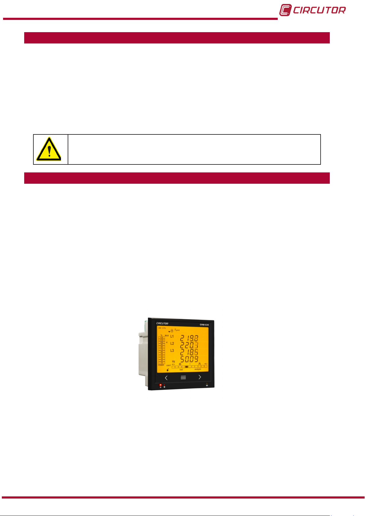
2�- PRODUCT DESCRIPTION
The CVM-C10 unit measures, calculates and displays the main electrical parameters of the
following networks: single-phase, two-phase, with and without neutral, balanced three-phase,
with ARON measurements or unbalanced. The measurement will be taken in RMS with the
three AC voltage inputs and three current inputs.
There are 3 versions of the unit, depending on the type of current input:
CVM-C10-ITF, indirect current measurement with /5A or /1A transformers.
CVM-C10-ITF-IN, indirect current measurement with /5A or /1A transformers and an
input to measure the neutral current.
CVM-C10-MC, indirect current measurement with efcient transformers of the
MC1 and MC3 series.
CVM-C10-mV indirect current measurement with /0.333V transformers.
The unit features:
- 3 keys that allow you to browse between the various screens and program the unit.
- 3 indicator LEDs: CPU, ALARM and KEY.
- LCD display, displays all parameters,
- 2 digital inputs, used to select the tariff or detect the logic state of external signals.
- 2 digital outputs, fully programmable.
(Not available in the CVM-C10-ITF-IN model)
- 2 alarm relays, fully programmable.
- RS-485 Communications, with two serial protocols: MODBUS RTU© and BACnet.
Instruction Manual
7
Page 8
CVM-C10
3�- UNIT INSTALLATION
3.1.- PRIOR RECOMMENDATIONS
In order to use the unit safely, it is critical that individuals who handle it follow the
safety measures set out in the standards of the country where it is being used,
use the necessary personal protective equipment, and pay attention to the various warnings indicated in this instruction manual.
The CVM-C10 unit must be installed by authorised and qualied staff.
The power supply plug must be disconnected and measuring systems switched off before han-
dling, altering the connections or replacing the unit. It is dangerous to handle the unit while it is
powered.
Also, it is critical to keep the cables in perfect condition in order to avoid accidents, personal
injury and damage to installations.
The manufacturer of the unit is not responsible for any damage resulting from failure by the
user or installer to heed the warnings and/or recommendations set out in this manual, nor for
damage resulting from the use of non-original products or accessories or those made by other
manufacturers.
If an anomaly or malfunction is detected in the unit, do not use it to take any measurements.
Inspect the work area before taking any measurements. Do not take measurements in danger-
ous areas or where there is a risk of explosion.
Disconnect the unit from the power supply (unit and measuring system power
supply) before maintaining, repairing or handling the unit's connections.
Please contact the after-sales service if you suspect that there is an operational
fault in the unit.
8
Instruction Manual
Page 9

CVM-C10
3.2.- INSTALLATION
The unit will be installed on a panel (92
+0.8
x 92
+0.8
mm panel drill hole, in compliance with DIN
43700). All connections are located inside the electric panel.
Terminals, opening covers or removing elements can expose parts that are hazardous to the touch while the unit is powered. Do not use the unit until it is fully
installed.
The unit must be connected to a power circuit that is protected with gl (IEC 269) or M type fuses
with a rating of 0.5 to 2 A. It must be tted with a circuit breaker or equivalent device, in order to
be able to disconnect the unit from the power supply network.
The power and voltage measuring circuit must be connected with cables that have a minimum
cross-section of 1mm2.
The secondary line of the current transformer will have a minimum cross-section of 2.5 mm2.
Instruction Manual
9
Page 10
3.3.- UNIT TERMINALS
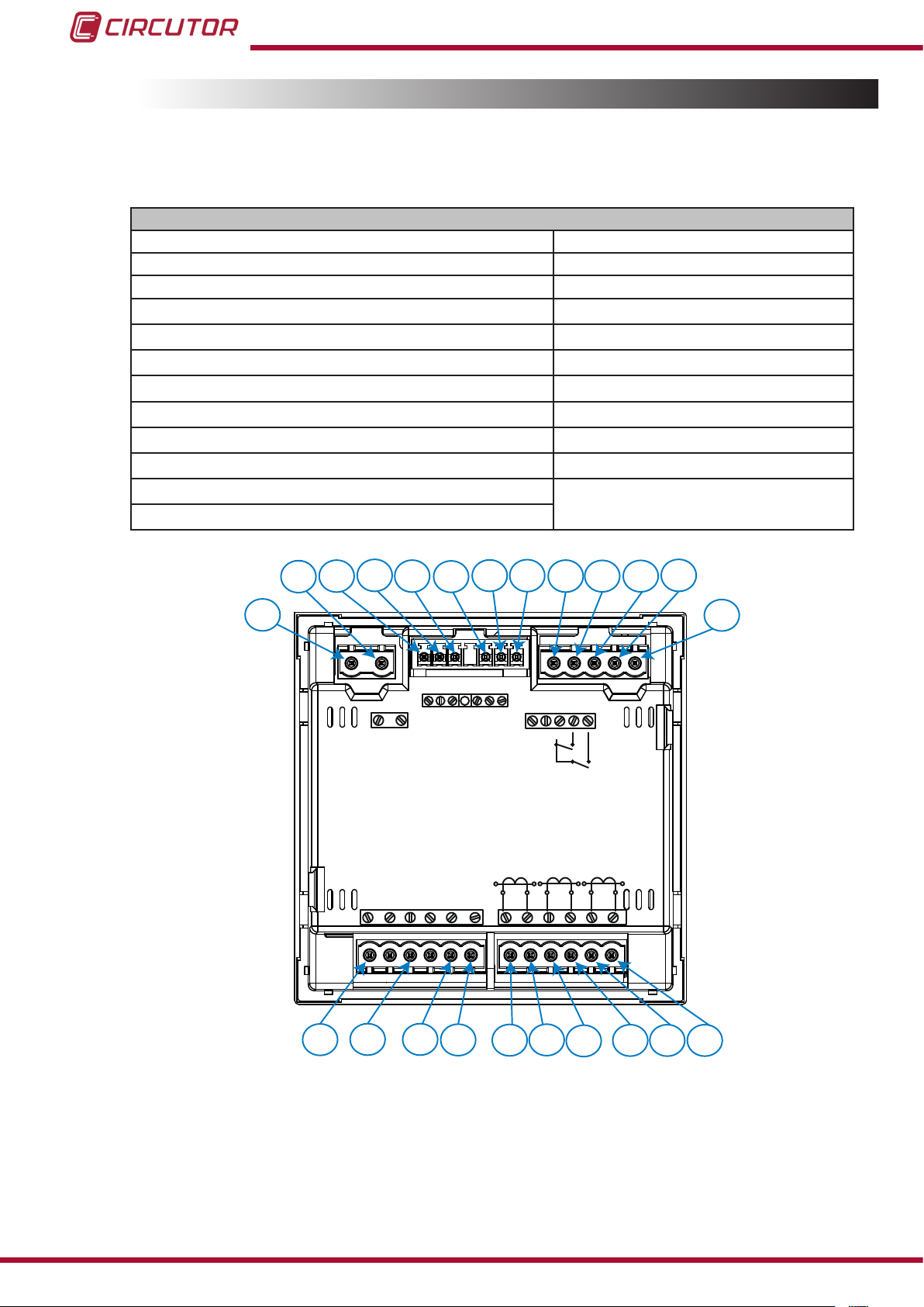
3�3�1�- List of terminals, CVM-C10-ITF, CVM-C10-MC and CVM-C10-mV models
Table 2:List of terminals of the CVM-C10-ITF, CVM-C10-MC and CVM-C10-mV�
Unit terminals
1 : A1 Auxiliary power supply. 13: I2, digital input 2 / tariff selection
2: A2 Auxiliary power supply. 14: V
3: Rc, Common relay output 15: V
4: R2, Relay output 2
5: R1, Relay output 1
6: CT, Common digital output.
7: T2, Digital output 2
8: T1, Digital output 1
9: A(+), RS485
10: B(-), RS485
11: GND, for RS485 and digital inputs
12: I1, digital input 1 / tariff selection
Voltage input L1
L1,
Voltage input L2
L2,
16: VL3,Voltage input L3
17: N, Neutral
18: S1
Current input L1
,
19: S2, Current input L1
20: S1, Current input L2
21: S2, Current input L2
22: S1, Current input L3
23: S2, Current input L3
CVM-C10
GND
L2
9
INPUTS
I1 I2
P1 P2
S1 S2
10 11 12
13
L3
3 4 5 6 7
2
8
1
OUTPUTS
S0-
S0+ S0+
RS485
P1 P2
L1
S1 S2
A(+) B(-)
P1 P2
S1 S2
POWER SUPPLY
520V
L1
V
Rc R2 R1 Tc T2 T1
Ph-NPh-Ph
300V
~
V
~
L3L2
NV
10
14 15 16 17
18 19 20 21 22 23
Figure 1:Terminals of the CVM-C10-ITF, CVM-C10-MC and CVM-C10-mV�
Instruction Manual
Page 11

CVM-C10
3�3�2�- List of terminals, CVM-C10-ITF-IN models�
Table 3:List of terminals of the CVM-C10-ITF-IN�
Unit terminals
1 : A1 Auxiliary power supply. 13: I2, digital input 2 / tariff selection
2: A2 Auxiliary power supply. 14: V
3: Rc, Common relay output 15: V
4: R2, Relay output 2
5: R1, Relay output 1
6: Not connected
7: S2, Neutral current input
8: S1, Neutral current input
9: A(+), RS485
10: B(-), RS485
11: GND, for RS485 and digital inputs
12: I1, digital input 1 / tariff selection
Voltage input L1
L1,
Voltage input L2
L2,
16: VL3,Voltage input L3
17: N, Neutral
18: S1
Current input L1
,
19: S2, Current input L1
20: S1, Current input L2
21: S2, Current input L2
22: S1, Current input L3
23: S2, Current input L3
GND
L2
9
INPUTS
I1 I2
P1 P2
S1 S2
10 11 12
13
L3
3 4 5 6 7
2
8
1
POWER SUPPLY
520V
L1
V
OUTPUTS
Rc R2 R1
~
V
Ph-NPh-Ph
300V
L3L2
S2
~
NV
S1
LN
P1P2
P1 P2
L1
S1 S2
RS485
A(+) B(-)
P1 P2
S1 S2
Instruction Manual
14 15 16 17
18 19 20 21 22 23
Figure 2:Terminals of the CVM-C10-ITF-IN�
11
Page 12
CVM-C10
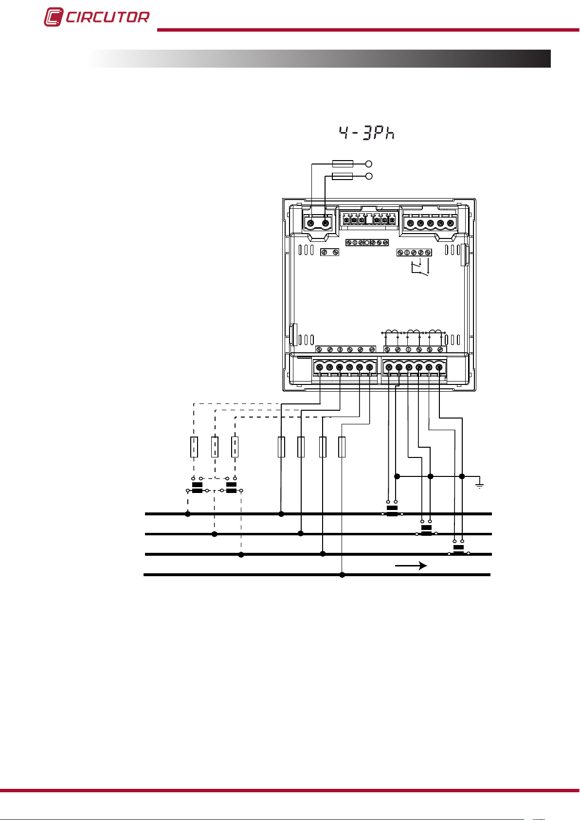
3.4.- CONNECTION DIAGRAM
3�4�1�- Measuring Three-Phase Networks with a 4-wire connection, CVM-C10-ITF and
CVM-C10-mV model�
Measurement system:
Power
Supply
OUTPUTS
S0-
POWER SUPPLY
S0+ S0+
Rc R2 R1 Tc T2 T1
RS485
A(+) B(-)
GND
INPUTS
I1 I2
520V
L3L2
V
L1
V
L1
NV
S1 S2
Ph-NPh-Ph
P1 P2
~
300V
~
P1 P2
L2
S1 S2
P1 P2
L3
S1 S2
VL1 VL2 VL3
V
L1
L2
L3
b
a
A B
a
b
A B
L1 VL2
VL3 N
S1 S2
P1
P2
P1
S1 S2
P2
S1 S2
P1
P2
LOAD
N
Figure 3: Three-Phase measuring with a 4-wire connection, CVM-C10-ITF and CVM-C10-mV model�
12
Instruction Manual
Page 13
CVM-C10
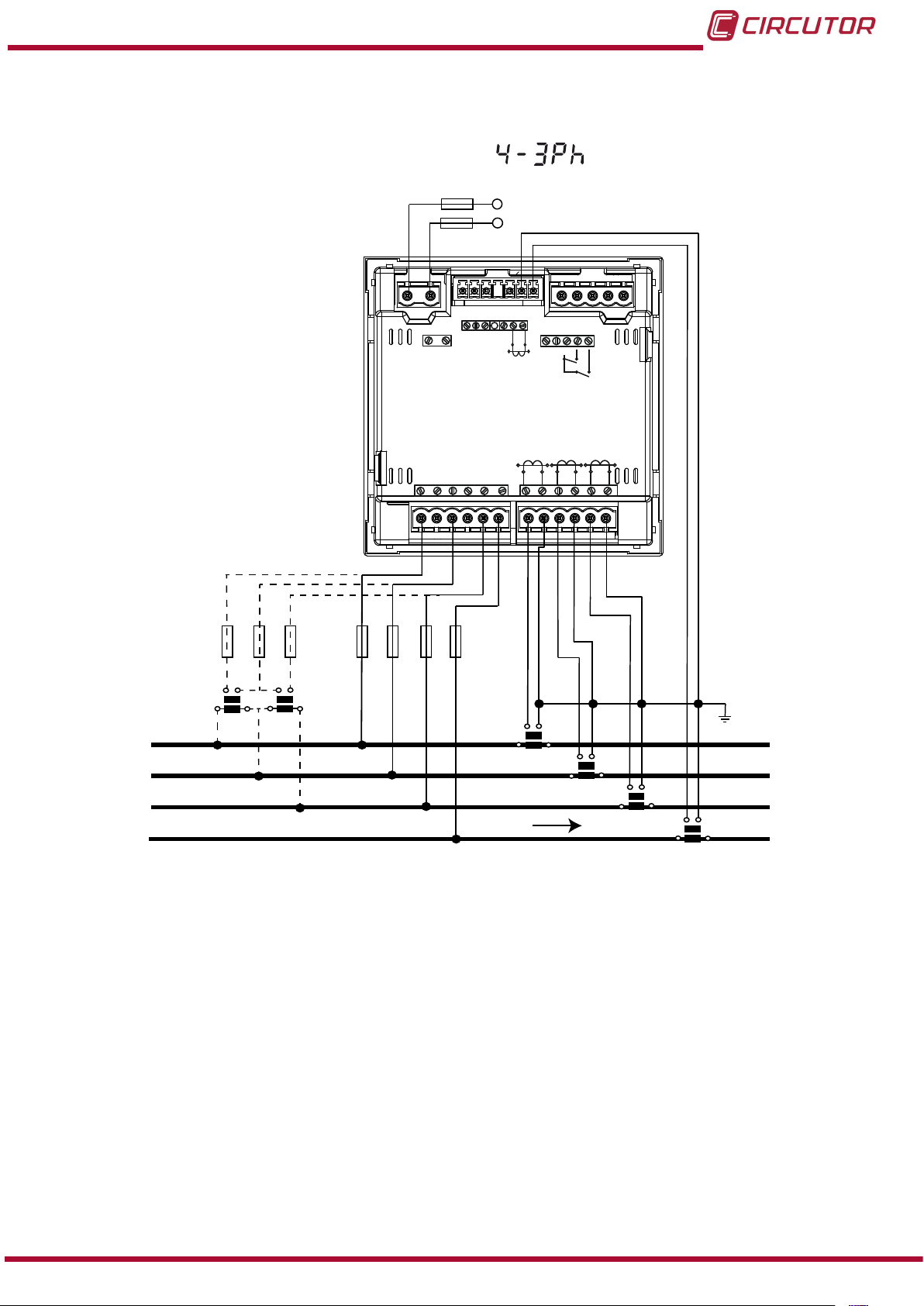
3�4�2�- Measuring Three-Phase Networks with a 4-wire connection, CVM-C10-ITF-IN
model�
Measurement system:
Power
Supply
L1
L2
L3
POWER SUPPLY
520V
L1
V
OUTPUTS
Rc R2 R1
S2
LN
Ph-NPh-Ph
P1 P2
~
300V
~
L3L2
V
NV
S1 S2
S1
P1P2
L1
RS485
A(+) B(-)
S1 S2
INPUTS
GND
P1 P2
L2
I1 I2
P1 P2
S1 S2
L3
VL1 VL2 VL3
L1 VL2
V
a
b
a
A B
b
A B
N
VL3 N
P1
LOAD
S1
S2
P2
S2
S1
P2
P1
S1 S2
P1
P2
S1 S2
P1
P2
Figure 4: Three-Phase Measuring with a 4-wire connection, CVM-C10-ITF-IN model�
Instruction Manual
13
Page 14
CVM-C10
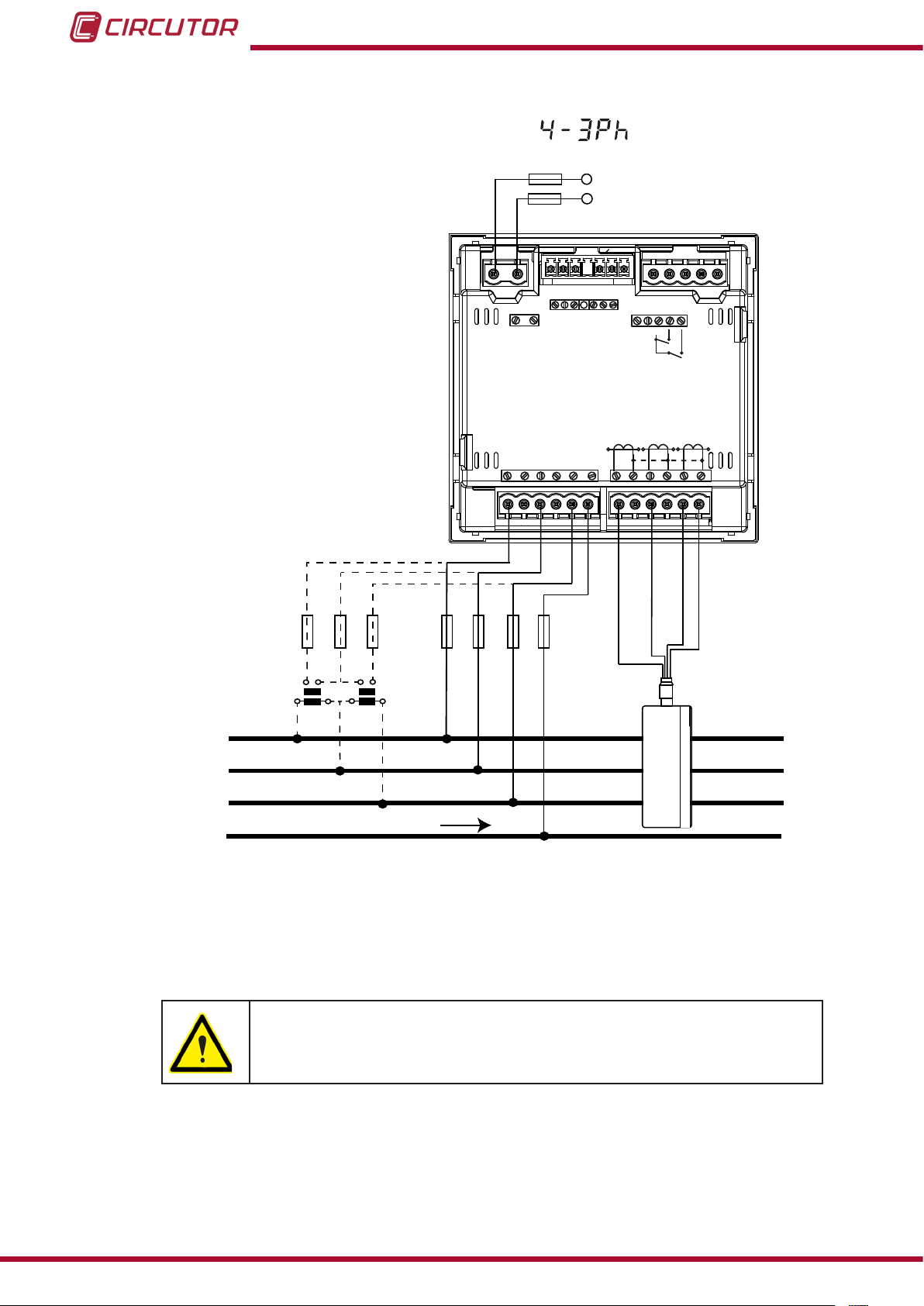
3�4�3�- Measuring Three-Phase Networks with a 4-wire connection, CVM-C10-MC model�
Measurement system:
Power
Supply
OUTPUTS
S0-
POWER SUPPLY
S0+ S0+
Rc R2 R1 Tc T2 T1
RS485
A(+) B(-)
GND
INPUTS
I1 I2
VL1 VL2 VL3
a
b
a
A B
A B
520V
L3L2
V
L1
V
L1
NV
S1 S2
Ph-NPh-Ph
P1 P2
~
300V
~
Grey/Pink
V
L1 VL2
b
VL3 N
P1 P2
L2
S1 S2
Green/White
P1 P2
L3
S1 S2
Red/Blue
L1
L2
L3
N
LOAD
2P1 1P1
3P1
2P2 1P2
3P2
Figure 5: Three-Phase measuring with a 4-wire connection, CVM-C10-MC model�
Brown/Green
14
The MC transformer secondary value is set to 0.250 A (xed value)
Instruction Manual
Page 15
CVM-C10
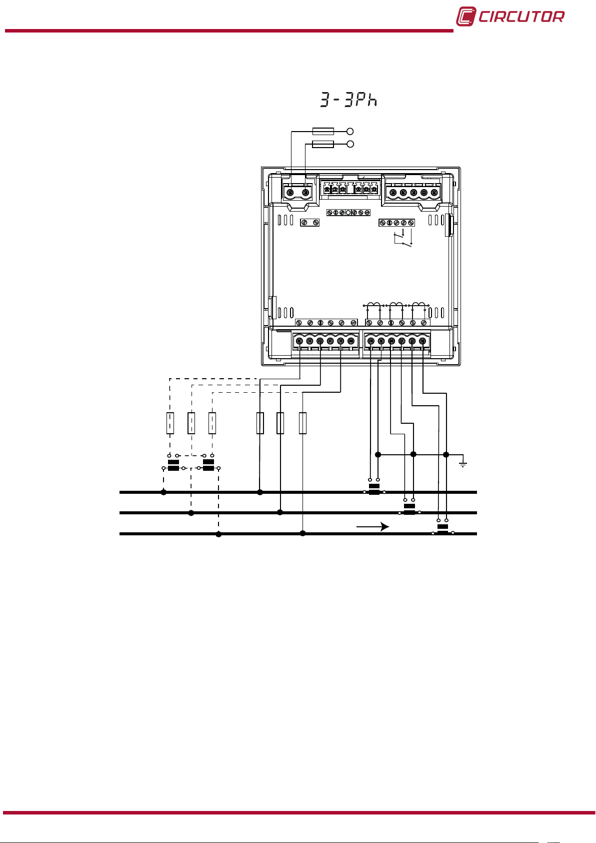
3�4�4�- Measuring Three-Phase Networks with a 3-wire connection, CVM-C10-ITF and
CVM-C10-mV model�
Measurement system:
Power
Supply
OUTPUTS
S0-
POWER SUPPLY
S0+ S0+
Rc R2 R1 Tc T2 T1
RS485
A(+) B(-)
GND
INPUTS
I1 I2
V
520V
L1
Ph-NPh-Ph
P1 P2
~
300V
~
L3L2
V
L1
NV
S1 S2
P1 P2
L2
S1 S2
P1 P2
L3
S1 S2
VL1 VL2 VL3
L1 VL2
L1
L2
L3
V
a
b
a
A
B
b
A B
VL3
LOAD
S1 S2
P1
P2
S1 S2
P1
P2
P1
S1 S2
P2
Figure 6: Three-Phase measuring with a 3-wire connection, CVM-C10-ITF and CVM-C10-mV model�
Instruction Manual
15
Page 16
CVM-C10
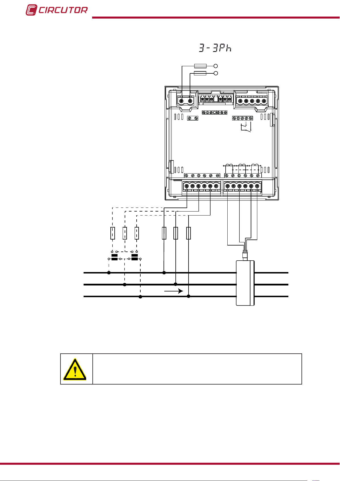
3�4�5�- Measuring Three-Phase Networks with a 3-wire connection, CVM-C10-MC model�
Measurement system:
Power
Supply
OUTPUTS
S0-
POWER SUPPLY
S0+ S0+
Rc R2 R1 Tc T2 T1
RS485
A(+) B(-)
GND
INPUTS
I1 I2
VL1 VL2 VL3
a
b
a
A B
A B
520V
L3L2
V
L1
V
L1
NV
S1 S2
Ph-NPh-Ph
P1 P2
~
300V
~
Grey/Pink
V
L1 VL2
b
VL3 N
P1 P2
L2
S1 S2
Green/White
P1 P2
L3
S1 S2
Red/Blue
L1
L2
2P1 1P1
2P2 1P2
LOAD
L3
3P1
3P2
Figure 7: Three-Phase measuring with a 3-wire connection, CVM-C10-MC model�
Brown/Green
16
The MC transformer secondary value is set to 0.250 A (xed value)
Instruction Manual
Page 17
CVM-C10
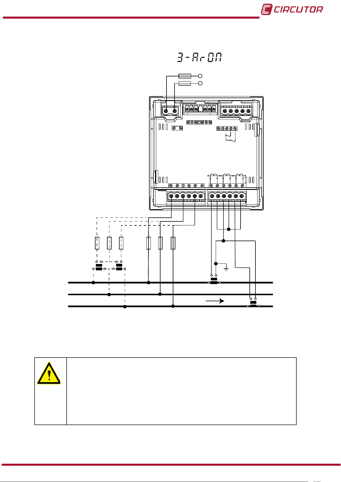
3�4�6�- Measuring Three-Phase Networks with a 3-wire connection and transformers
with an ARON connection, CVM-C10-ITF, CVM-C10-MC and CVM-C10-mV models�
Measurement system:
Power
Supply
OUTPUTS
S0-
POWER SUPPLY
S0+ S0+
Rc R2 R1 Tc T2 T1
RS485
A(+) B(-)
GND
INPUTS
I1 I2
520V
L3L2
V
L1
V
L1
NV
S1 S2
Ph-NPh-Ph
P1 P2
~
300V
~
P1 P2
L2
S1 S2
P1 P2
L3
S1 S2
VL1 VL2 VL3
L1 VL2
L1
L2
L3
a
A B
b
a
b
A B
V
VL3
LOAD
S1
S2
P2
P1
S1 S2
P2
P1
Figure 8: Three-Phase measuring with a 3-wire connection and transformers with an ARON connection, CVM-C10-
ITF, CVM-C10-MC and CVM-C10-mV models�
CVM-C10-ITF model:
The transformer secondary value must be 5A or 1A
CVM-C10-MC model:
The MC transformer secondary value is set to 0.250 A (xed value)
CVM-C10-mV model:
The transformer secondary value must be 0.333 V
Instruction Manual
17
Page 18
CVM-C10
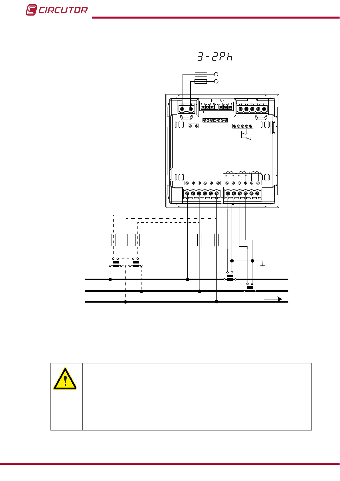
3�4�7�- Measuring Two-Phase Networks with a 3-wire connection, CVM-C10-ITF,
CVM-C10-MC and CVM-C10-mV models�
Measurement system:
Power
Supply
OUTPUTS
S0-
POWER SUPPLY
S0+ S0+
Rc R2 R1 Tc T2 T1
RS485
A(+) B(-)
GND
INPUTS
I1 I2
L1
L2
Ph-NPh-Ph
P1 P2
~
300V
~
VL1 N
b
a
A
B
V
L2
a b
A B
520V
V
L1
V
L1 VL2 N
V
L3L2
NV
P1
L1
S1 S2
S1 S2
N
P1 P2
L2
S1 S2
P2
P1
P1 P2
S1 S2
S1 S2
LOAD
L3
P2
Figure 9: Measuring Two-Phase Networks with a 3-wire connection, CVM-C10-ITF, CVM-C10-MC and CVM-C10-mV
models�
18
CVM-C10-ITF model:
The transformer secondary value must be 5A or 1A
CVM-C10-MC model:
The MC transformer secondary value is set to 0.250 A (xed value)
CVM-C10-mV model:
The transformer secondary value must be 0.333 V
Instruction Manual
Page 19
CVM-C10
3�4�8�- Measuring Two-Phase Networks with a 3-wire connection, CVM-C10-ITF-IN model�
Measurement system:
Power
Supply
L1
L2
OUTPUTS
POWER SUPPLY
Rc R2 R1
S2
LN
Ph-NPh-Ph
P1 P2
~
300V
~
520V
L3L2
V
L1
VL1 N
a
A
b
B
V
L2
a
b
A B
V
V
L1 VL2 N
NV
S1 S2
S1
P1
N
RS485
A(+) B(-)
S1
P1P2
L1
S2
LOAD
GND
P1 P2
L2
S1 S2
P2
P1
INPUTS
S1
I1 I2
P1 P2
S1 S2
L3
S2
P2
S2
S1
P2
P1
Figure 10: Measuring Two-Phase Networks with a 3-wire connection, CVM-C10-ITF-IN model�
Instruction Manual
19
Page 20
CVM-C10
3�4�9�- Measuring Single-Phase Networks, phase to phase, with a 2-wire connection,
CVM-C10-ITF, CVM-C10-MC and CVM-C10-mV models�
Measurement system:
Power
Supply
OUTPUTS
S0-
POWER SUPPLY
S0+ S0+
Rc R2 R1 Tc T2 T1
RS485
A(+) B(-)
GND
INPUTS
I1 I2
L1
VL1
a b
A B
VL2
L1
V
V
L1 VL2
520V
Ph-NPh-Ph
P1 P2
~
300V
~
L3L2
V
NV
L1
S1 S2
S1 S2
P1
P1 P2
L2
S1 S2
P2
P1 P2
L3
S1 S2
LOAD
L2
Figure 11: Measuring Single-Phase Networks, phase to phase, with a 2-wire connection, CVM-C10-ITF, CVM-C10-MC
and CVM-C10-mV models�
20
CVM-C10-ITF model:
The transformer secondary value must be 5A or 1A
CVM-C10-MC model:
The MC transformer secondary value is set to 0.250 A (xed value)
CVM-C10-mV model:
The transformer secondary value must be 0.333 V
Instruction Manual
Page 21
CVM-C10
3�4�10�- Measuring Single-Phase Networks, phase to neutral, with a 2-wire connection,
CVM-C10-ITF, CVM-C10-MC and CVM-C10-mV models�
Measurement system:
Power
Supply
OUTPUTS
S0-
POWER SUPPLY
S0+ S0+
Rc R2 R1 Tc T2 T1
RS485
A(+) B(-)
GND
INPUTS
I1 I2
L1
VL1
a b
A B
520V
L3L2
V
L1
V
L1
NV
S1 S2
Ph-NPh-Ph
P1 P2
~
300V
~
N
L1 N
V
S1
P1
P1 P2
S1 S2
S2
P2
P1 P2
L3
L2
S1 S2
LOAD
N
Figure 12: Measuring Single-Phase Networks, phase to neutral, with a 2-wire connection, CVM-C10-ITF, CVM-C10-MC
and CVM-C10-mV models�
CVM-C10-ITF model:
The transformer secondary value must be 5A or 1A
CVM-C10-MC model:
The MC transformer secondary value is set to 0.250 A (xed value)
CVM-C10-mV model:
The transformer secondary value must be 0.333 V
Instruction Manual
21
Page 22
4�- OPERATION
0º
90º
180º
-90º
Capacitive
Capacitive
Inductive
Inductive
Generation
Power
Consumption
Power
Single-phaseThree-phase
Single-phase
Single-phase
Single-phase
Three-phase
Three-phase
Three-phase
k
k
k
k
k
k
k
k
k
k
k
k
k
k
k
k
k
k
k
k
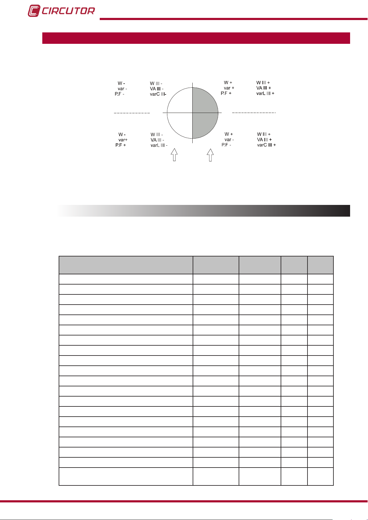
The CVM-C10 is a four-quadrant power analyzer (consumption and generation).
CVM-C10
Figure 13: Four quadrants of CVM-C10
4.1.- MEASURING PARAMETERS
The unit displays the electrical parameters shown in Table 4.
Table 4: Measuring parameters of the CVM-C10�
Parameter Units
Phase-neutral voltage Vph-N
Phase-phase voltage Vph-ph
Current A
Frequency Hz
Active power M/kW
Apparent power M/kVA
Total Reactive Power M/kvar
Total Reactive Power - Consumption M/kvar
Total Reactive Power - Generation M/kvar
Total Inductive Reactive Power M/kvarL
Inductive Reactive Power - Consumption M/kvarL
Inductive Reactive Power - Generation M/kvarL
Total Capacitive Reactive Power M/kvarC
Capacitive Reactive Power - Consumption M/kvarC
Capacitive Reactive Power - Generation M/kvarC
Power factor PF
Cos φ φ
THD % Voltage % THD V
THD % Current % THD A
Harmonic Breakdown - Voltage
(up to the 31st order harmonic)
harm V
Phases
L1-L2-L3
Total
III
N
22
Instruction Manual
Page 23
CVM-C10
Harmonic Breakdown - Current
(up to the 31st order harmonic)
Total Active Energy M/kWh
Total Inductive Reactive Energy M/kvarLh
Total Capacitive Reactive Energy M/kvarCh
Total Apparent Energy M/kVAh
Active Energy Tariff 1 M/kWh
Inductive Reactive Energy Tariff 1 M/kvarLh
Capacitive Reactive Energy Tariff 1 M/kvarCh
Apparent Energy Tariff 1 M/kVAh
Active Energy Tariff 2 M/kWh
Inductive Reactive Energy Tariff 2 M/kvarLh
Capacitive Reactive Energy Tariff 2 M/kvarCh
Apparent Energy Tariff 2 M/kVAh
Active Energy Tariff 3 M/kWh
Inductive Reactive Energy Tariff 3 M/kvarLh
Capacitive Reactive Energy Tariff 3 M/kvarCh
Apparent Energy Tariff 3 M/kVAh
Maximum Current Demand A
Maximum Demand of Active power M/kW
Maximum Demand of Apparent Power M/kVA
No. of hours hours
Cost COST
CO2 Emissions kgCO
Table 4 ( Continuation ) : Measuring parameters of the CVM-C10�
Parameter Units
harm V
Phases
L1-L2-L3
Total
III
N
Parameter Units Tariff: T1-T2-T3 Total
2
4.2.- KEYBOARD FUNCTIONS
The CVM-C10 has 3 keys that allow you to browse between the various screens and program
the unit.
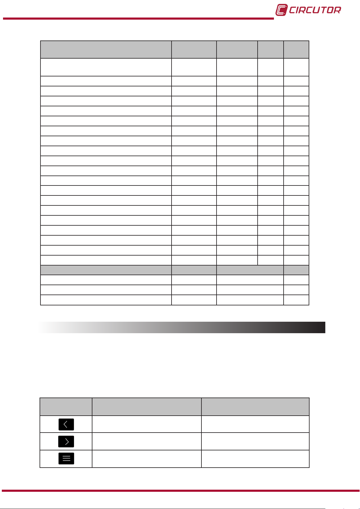
Key functions on measuring screens (Table 5):
Table 5: Key functions on measuring screens�
Key Short keystroke
Instruction Manual
Previous screen Display of minimum value
Next screen Display of maximum value
Browsing the different proles
(analyzer, user, e3)
Accessing the programming menu
Long keystroke
(2 s)
23
Page 24
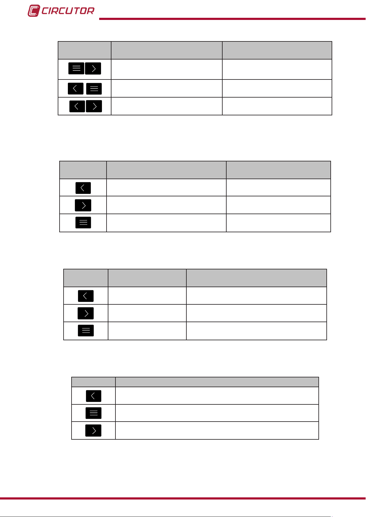
Table 5 (Continuation ) : Key functions on measuring screens�
Key Short keystroke
CVM-C10
Long keystroke
(2 s)
Display of the Maximum Demand
Active alarm information
Unlocks the active alarm
Key functions on harmonics screens (Table 6):
Table 6: Key functions on harmonics screens�
Key Short keystroke
Output of the harmonics screens
Next screen
Browsing the different types of harmonics
Accessing the programming
menu
Key functions on the programming menu, query mode (Table 7):
Table 7: Key functions on the programming menu, query mode�
Key Short keystroke
Long keystroke
Long keystroke
(2 s)
(2 s)
Previous screen Programming output
Next screen Programming output
Opening the programming menu in the edit
mode
Key functions on the programming menu, edit mode (Table 8):
Table 8: Key functions on the programming menu, edit mode�
Key Keystroke
Next page
Increases the digits (0-9) or rotates between the different options.
Moves an editable digit (ashing)
24
Instruction Manual
Page 25
CVM-C10
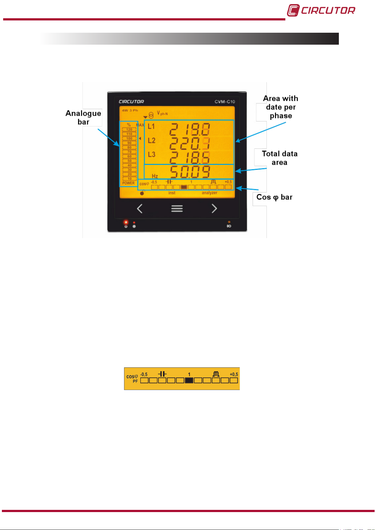
4.3.- DISPLAY
The unit has a backlit LCD display showing all the parameters listed in Table 3.
The display is divided into four areas (Figure 14):
Figure 14: CVM-C10 Display areas
The area with data per phase displays the instantaneous, maximum and minimum
values of each phase being measured or calculated by the unit.
The total data area displays the totals of the values being measured or calculated by
the unit.
Analogue bar, displays the % of the current power of the installation.
Cos φ - PF Bar, displays the value of the system's Cos φ or power factor in real time.
4�3�1� COS φ - PF (POWER FACTOR) BAR
Figure 15: Cos φ - PF Bar
This bar displays the value of the installation's cos φ or power factor in real time.
The parameter that will be displayed is selected on the programming menu. ( “4.9.13. Selecting
the Cos φ - PF bar on the display”)
Instruction Manual
25
Page 26

4�3�2� ANALOGUE BAR
Figure 16: Analogue Bar
The analogue bar displays two parameters:
Current power of the installation in %
This parameter is displayed in 12 divisions, each one represents 10%, into which the
analogue bar is divided.
The unit calculates the current power of the installation using the formula:
P = V*I*cos(φ)
Where the voltage and the cos(φ) are the installation’s current values.
The current is referenced in its full scale. (100% is the full scale of the unit and a value
above 100% indicates that it is out of range).
CVM-C10
The maximum system demand reached, i.e., the maximum power value
reached since the unit was started, expressed as a percentage.
This value is displayed with the icon .
The value and the maximum and minimum values are reset. ( “4.9.14. Deleting maximum
and minimum values”)
Example: Figure 16 shows that the installation performance is 50% and that the maximum de-
mand of the system is 80%.
4�3�3� OTHER SYMBOLS ON THE DISPLAY
The following are also shown on the display:
Type of installation
The type of installation to which the unit is connected can be selected on the programming menu, ( “4.9.8. Type of installation”). The selected type is shown on the top left of
the display.
State of digital inputs
If the digital inputs have been activated, the top left of the display will show
the icons that indicate that the digital input is active.
26
Instruction Manual
Page 27

CVM-C10
4.4.- LED INDICATORS
The CVM-C10 unit has 3 LEDs:
- CPU, indicates that the unit is on, ashing each second.
- ALARM, indicates that an alarm has been activated if it is on
- KEY, LED that is lit when any key is pressed.
Figure 17:LED Indicators of the CVM-C10�
4.5.- OPERATION PROFILES
The CVM-C10 has 3 operation proles. The display screens will be opened for the corresponding prole:
Analyzer prole, analyzer,
Electrical energy efciency prole, e3,
User prole, user,
4�5�1� ANALYZER PROFILE
This prole is identied with the analyzer symbol on the bottom of the screen (Figure 18)
Instruction Manual
Figure 18: CVM-C10 screen with the analyzer prole.
27
Page 28

CVM-C10
The unit displays 11 different screens for the analyzer prole (Table 9)
Use keys and to browse the different screens.
The inst symbol on the bottom of the screen indicates that the values being displayed are of
the instantaneous type.
Table 9: Analyzer prole screens.
Screen Parameters (units)
phase-phase Voltage L1-L2 (V
phase-phase Voltage L2-L3 (V
phase-phase Voltage L3-L1 (V
Frequency (Hz)
phase-neutral Voltage L1 (V
phase-neutral Voltage L2 (V
phase-neutral Voltage L3 (V
Frequency (Hz)
Current L1 (A)
Current L2 (A)
Current L3 (A)
Neutral Current (A)
(1)
ph-ph
ph-ph
ph-ph
ph-N
ph-N
ph-N
)
)
)
)
)
)
(1)
Not available for the and
installation types.
Active Power L1 (M/K W)
Active Power L2 (M/K W)
Active Power L3 (M/K W)
Active Power III (M/K W)
The generation values are not measured
when the 2 quadrant option is selected.
28
Instruction Manual
Page 29

CVM-C10
Table 9 ( Continuation ) : Analyzer profile screens�
Screen Parameters (units)
Apparent Power L1 (M/KVA)
Apparent Power L2 (M/KVA)
Apparent Power L3 (M/KVA)
Apparent Power III (M/KVA)
The generation values are not measured
when the 2 quadrant option is selected.
Inductive Reactive Power L1 (M/KvarL)
Inductive Reactive Power L2 (M/KvarL)
Inductive Reactive Power L3 (M/KvarL)
Inductive Reactive Power III (M/KvarL)
Capacitive Reactive Power L1
(M/KvarC)
Capacitive Reactive Power L2
(M/KvarC)
Capacitive Reactive Power L3
(M/KvarC)
Capacitive Reactive Power III
(M/KvarC)
THD % Voltage L1 (V THD %)
THD % Voltage L2 (V THD %)
THD % Voltage L3 (V THD %)
THD % Current L1 (A THD %)
THD % Current L2 (A THD %)
THD % Current L3 (A THD %)
Instruction Manual
29
Page 30

Table 9 ( Continuation ) : Analyzer profile screens�
Screen Parameters (units)
Power factor L1 (PF)
Power factor L2 (PF)
Power factor L3 (PF)
Power factor III (PF)
Cos φ L1 (cos φ)
Cos φ L2 (cos φ)
Cos φ L3 (cos φ)
Cos φ III (cos φ)
CVM-C10
Also displayed on these screens are:
Maximum values
To see the maximum values of the screen being displayed, press the key for 2
seconds.
The max symbol is shown on the display (Figure 19)
The maximum and minimum values are reset on the programming menu.
( “4.9.14. Deleting maximum and minimum values”)
Figure 19: Analyzer prole screen displaying the maximum values.
30
Minimum values
To see the minimum values of the screen being displayed, press the key for 2
seconds.
The min symbol will be displayed (Figure 20)
The maximum and minimum values are reset on the programming menu.
( “4.9.14. Deleting maximum and minimum values”)
Instruction Manual
Page 31

CVM-C10
Figure 20: Analyzer prole screen displaying the minimum values.
Maximum Demand
The unit calculates the maximum demand of the following:
• Current
• Three-Phase Active Power.
•Three-Phase Apparent Power.
This value can be displayed on the display screen of the parameter by pressing the
and keys at the same time.
The dem symbol appears on the display (Figure 21)
Figure 21: Analyzer prole screen displaying the maximum demand values.
Press keys or to stop displaying the maximum demand values.
The maximum demand values are reset on the programming menu:
“4.9.10. Deleting maximum demand”
4�5�2� e3 PROFILE
This prole is identied with the e3 symbol on the bottom of the screen (Figure 22).
Figure 22: CVM-C10 screen with the e3 prole.
Instruction Manual
31
Page 32

CVM-C10
The installation's consumed and generated energy are displayed on the e3 prole of the unit.
The installation status is also displayed:
Installation is consuming energy.
Installation is generating energy.
A long keystroke (3 sec) of key will display the generation values.
The generation values are identied with the negative sign on the screen, which appears in
front of each parameter.
A long keystroke (3 sec) of key will display the consumption values.
Use keys and to browse the different screens (short keystroke).
Table 10: Screens of the e3 prole.
Screen Parameters (units)
Active Energy Tariff 1 , T1 (M/KWh)
Active Energy Tariff 2 , T2 (M/KWh)
Active Energy Tariff 3 , T3 (M/KWh)
Total Active Energy (M/KWh)
Consumption and generation values
Only available for the 4 quadrant option.
Apparent Energy Tariff 1, T1 (M/KVAh)
Apparent Energy Tariff 2, T2 (M/KVAh)
Apparent Energy Tariff 3, T3 (M/KVAh)
Total Apparent Energy (M/KVAh)
Consumption and generation values
Only available for the 4 quadrant option.
Inductive Reactive Energy Tariff 1, T1 (M/KvarLh)
Inductive Reactive Energy Tariff 2, T2 (M/KvarLh)
Inductive Reactive Energy Tariff 3, T3 (M/KvarLh)
Total Inductive Reactive Energy (M/KvarLh)
32
Consumption and generation values
Only available for the 4 quadrant option.
Instruction Manual
Page 33

CVM-C10
Table 10 ( Continuation ) : Screens of the e3 profile�
Screen Parameters (units)
Capacitive Reactive Energy Tariff 1, T1 (M/KvarCh)
Capacitive Reactive Energy Tariff 2, T2 (M/KvarCh)
Capacitive Reactive Energy Tariff 3, T3 (M/KvarCh)
Total Capacitive Reactive Energy (M/KvarCh)
Consumption and generation values
Only available for the 4 quadrant option.
Cost Tariff 1, T1 (cost)
Cost Tariff 2, T2 (cost)
Cost Tariff 3, T3 (cost)
Total Cost (cost)
Consumption and generation values
CO2 Emissions Tariff 1, T1 (kgCO2)
CO2 Emissions Tariff 2, T2 (kgCO2)
CO2 Emissions Tariff 3, T3 (kgCO2)
Total CO2 Emissions (kgCO2)
Consumption and generation values
No. of hours Tariff 1, T1(hours)
No. of hours Tariff 2, T2(hours)
No. of hours Tariff 3, T3(hours)
Total No. of hours (hours)
Symbols T1, T2 and T3 on the display indicate the three tariffs available on the unit.
The corresponding symbol flashes to indicate the selected tariff.
Instruction Manual
33
Page 34

CVM-C10
4�5�3� USER
This prole is identied with the user symbol on the bottom of the screen (Figure 23).
Figure 23: Screen of the CVM-C10 with the user prole.
This prole displays the screens selected in the programming menu ( “4.9.11. Selecting the op-
eration prole”).
4.6.- HARMONICS
The unit can display the voltage and current harmonics, up to the 31st order harmonic, for each
one of the lines, L1, L2 and L3.
They must be activated in the programming menu to be displayed (“4.9.17. Activating the har-
monics display screen.”).
Press the key on the last prole screen to show all operation proles on the harmonics
display screens.
Harmonics are displayed as shown on Figure 24.
34
Figure 24: CVM-C10 Current harmonics screen�
Press key to open the next harmonics screen.
Press key to display the different types of harmonics:
• Voltage harmonics L1- L2 - L3
• Current harmonics L1- L2 -L3
Instruction Manual
Page 35

CVM-C10
4.7.- INPUTS
The CVM-C10 has two digital inputs (terminals 12 and 13 on Figure 1) that can be programmed
to operate as a logic or tariff selection input.
See “4.9.26. Operating mode of digital input 1” and “4.9.27. Operating mode of digital input 2”
The selected tariff can be determined in accordance with the status of the inputs, as shown in
Table 11.
Table 11: Selecting the tariff in accordance with the input status�
IN1, Input 1 IN2, Input 2
Logic input Tariff selection Logic input Tariff selection
x x T1
x 0 T1
x 1 T3
0 x T1
1 x T2
0 0 T1
0 1 T2
1 0 T3
1 1 T1
Tariff
4.8.- OUTPUTS
The unit features:
Two alarm relays (terminals 3, 4 and 5, as shown in Figure 1), fully programmable,
see “4.9.22. Programming alarm 1 (Relay 1)” and “4.9.23. Programming alarm 2 (Relay 2)”
Two digital outputs, optoisolated NPN transistors (terminals 6, 7 and 8 on
Figure 1), fully programmable, see “4.9.24. Programming alarm 3 (Digital output T1)” and
“4.9.25. Programming alarm 4 (Digital output T2)”.
Note: The digital outputs are not available on model CVM-C10-ITF-IN.
Instruction Manual
35
Page 36
CVM-C10
4.9.- PROGRAMMING
From the programming menu you can:
Lock the status of the menu.
Dene the transformation ratios.
Select the number of quadrants and type of installation.
Select the operation prole of the unit.
Program the carbon emission ratio, kgCO2,.
Program the cost ratio.
Program the maximum demand parameters.
Delete the energy meters and the maximum and minimum values.
Modify the display's backlight.
Activate the harmonic display option.
Program alarms.
Program Modbus communications
The CVM-C10 does not record programming changes until the programming is complete. If
the unit is RESET before nishing the programming or no key is pressed for 30 seconds, the
conguration will not be stored in the memory.
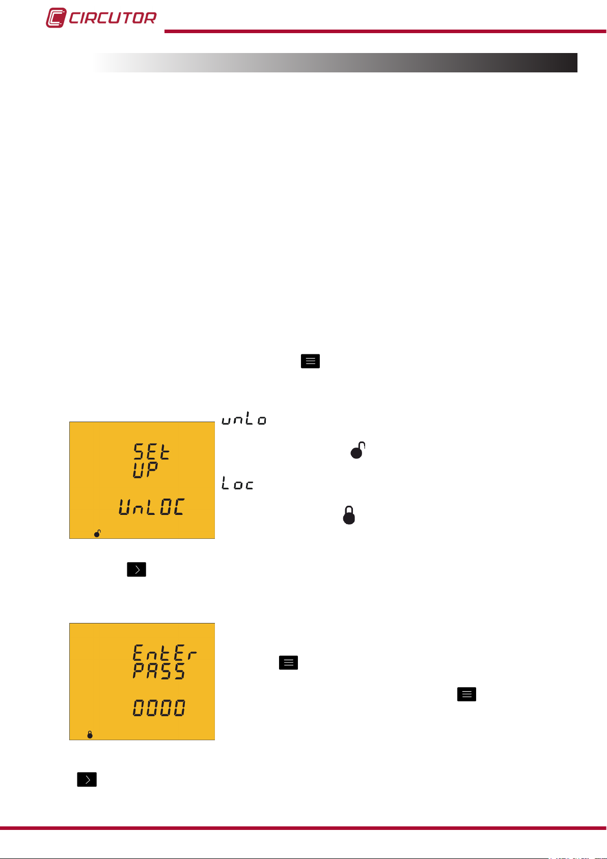
To enter the programming menu press the key for 3 seconds.
The home screen of the menu indicates whether the menu is locked or not:
When you enter the programming menu you can view and modify
the programming. Icon
on the display indicates that the unit
is not locked.
When you enter the programming you can view the programming
but not modify it. Icon
indicates the locking status.
Press key to access the rst programming step.
The following screen will be displayed if the programming menu is locked:
Enter the password in this screen to modify the programming
parameters.
Press key
for 3 seconds to edit the password. The prog icon
will be displayed on the bottom of the screen.
To enter or modify the value, press the
increasing the value of the ashing digit.
key repeatedly,
36
When the desired value is shown on the screen, move onto the next digit by pressing the key
to modify the other values.
Instruction Manual
Page 37
CVM-C10
If you press the key after changing the last digit, it will jump back to the rst digit so you
can modify the previously programmed values again.
To validate the data, press for 3 seconds and the prog icon will disappear from the display.
If the password is correct, the icon will change its status to not locked .
If you do not enter the password or it is incorrect, you can open the programming menu but it
cannot be modied.
The programming menu is unlocked for a short period of time and it will be locked again when
you exit the unit's menu.
To permanently unlock the unit, select the programming parameter “4.9.29. Locking the
programming”
Press key to access the next programming step.
Default password: 1234.
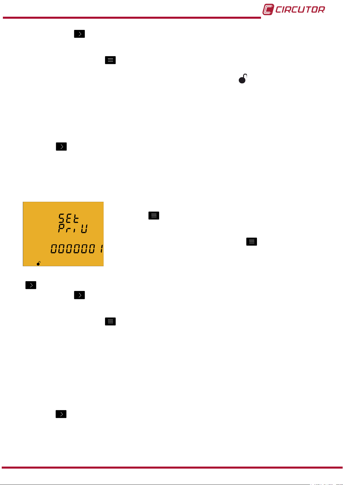
4�9�1� Primary voltage
On this screen the voltage transformer primary is programmed.
Press key
for 3 seconds to edit the transformer primary
value. The prog icon will be displayed on the bottom of the
screen.
To enter or modify the value, press the
key repeatedly,
increasing the value of the ashing digit.
When the desired value is shown on the screen, move onto the next digit by pressing the key
to modify the other values.
If you press the key after changing the last digit, it will jump back to the rst digit so you
can modify the previously programmed values again.
To validate the data, press for 3 seconds and the prog icon will disappear from the display.
The programmed value will be deleted if the entered value is higher than the maximum
programming value.
Maximum programming value: 599999.
Minimum programming value: 1.
Voltage ratio x Current ratio < 600000
NB: The ratio is the relation between the primary and the secondary.
Press key to access the next programming step.
Instruction Manual
37
Page 38
CVM-C10
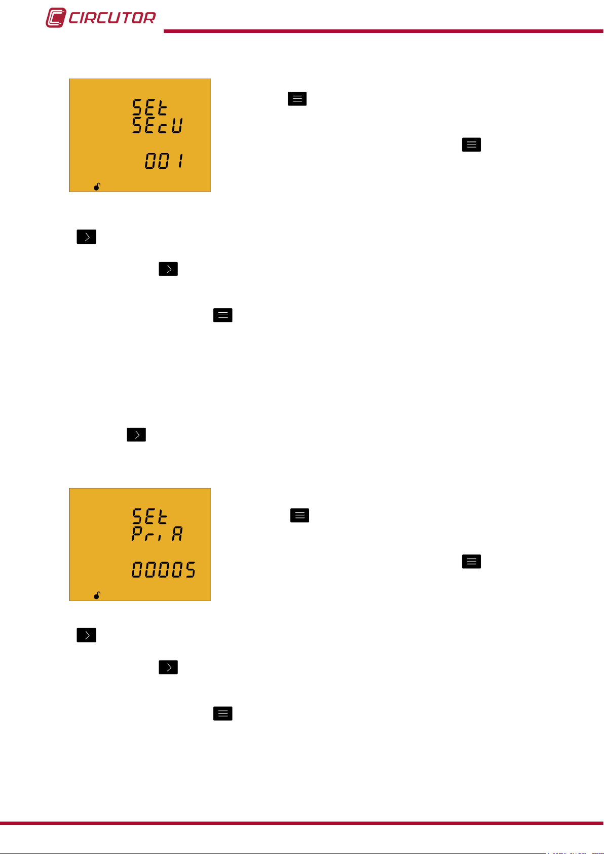
4�9�2� Secondary voltage
On this screen the voltage transformer secondary is programmed.
Press key
for 3 seconds to edit the transformer secondary
value. The prog icon will be displayed on the bottom of the
screen.
To enter or modify the value, press the
key repeatedly,
increasing the value of the ashing digit.
When the desired value is shown on the screen, move onto the next digit by pressing the key
to modify the other values.
If you press the key after changing the last digit, it will jump back to the rst digit so you
can modify the previously programmed values again.
To validate the data, press for 3 seconds and the prog icon will disappear from the display.
The programmed value will be deleted if the entered value is higher than the maximum
programming value.
Maximum programming value: 999.
Minimum programming value: 1.
Press key to access the next programming step.
4�9�3� Primary current
The current transformer primary is programmed on this screen.
Press key
for 3 seconds to edit the transformer primary
value. The prog icon will be displayed on the bottom of the
screen.
To enter or modify the value, press the
key repeatedly,
increasing the value of the ashing digit.
When the desired value is shown on the screen, move onto the next digit by pressing the key
38
to modify the remaining values.
If you press the key after changing the last digit, it will jump back to the rst digit so you
can modify the previously programmed values again.
To validate the data, press for 3 seconds and the prog icon will disappear from the display.
The programmed value will be deleted if the entered value is higher than the maximum
programming value.
Instruction Manual
Page 39

CVM-C10
Maximum programming value: 10000.
Minimum programming value: 1.
Voltage ratio x Current ratio < 600000
NB: The ratio is the relation between the primary and the secondary.
Press key to access the next programming step
4�9�4� Secondary current ( model CVM-C10-ITF)
On this screen the current transformer secondary is selected.
Press key
for 3 seconds to edit the transformer secondary
value. The prog icon will be displayed on the bottom of the
screen.
Press key
to browse the two possible options for the current
transformer secondary (1A or 5A).
To validate the data, press for 3 seconds and the prog icon will disappear from the display.
Press key to access the next programming step
4�9�5� Primary neutral current ( model CVM-C10-ITF-IN)
The neutral current transformer primary is programmed on this
screen.
Press key
for 3 seconds to edit the transformer primary
value. The prog icon will be displayed on the bottom of the
screen.
To enter or modify the value, press the
key repeatedly,
increasing the value of the ashing digit.
When the desired value is shown on the screen, move onto the next digit by pressing the key
to modify the remaining values.
If you press the key after changing the last digit, it will jump back to the rst digit so you
can modify the previously programmed values again.
To validate the data, press for 3 seconds and the prog icon will disappear from the display.
The programmed value will be deleted if the entered value is higher than the maximum
programming value.
Maximum programming value: 10000.
Minimum programming value: 1.
Press key to access the next programming step
Instruction Manual
39
Page 40

4�9�6�Secundary neutral current (model CVM-C10-ITF-IN)
The neutral current transformer secundary is programmed on this
screen.
Press key
for 3 seconds to edit the transformer secundary
value. The prog icon will be displayed on the bottom of the
screen.
CVM-C10
Press key
to browse the two possible options for the current
transformer secondary (1A or 5A).
To validate the data, press for 3 seconds and the prog icon will disappear from the display.
Press key to access the next programming step
4�9�7� Number of quadrants
The quadrant number on which the unit takes the measurement
is selected on this screen.
Press key
for 3 seconds to edit the number of quadrants. The
prog icon will be displayed on the bottom of the screen.
Press key
to browse the two options:
2 or 4 quadrants.
To validate the data, press for 3 seconds and the prog icon will disappear from the display.
Press key to access the next programming step
4�9�8� Type of installation
The type of installation is selected on this screen.
Press key
for 3 seconds to edit the type of installation. The
prog icon will be displayed on the bottom of the screen.
The key is used to browse the different options
Three-phase network measurement with a 4-wire connection.
Three-phase network measurement with a 3-wire connection.
Three-phase network measurement with a 3-wire connection and
transformers with an ARON connection .
Two-phase network measurement with a 3-wire connection.
Single-phase network measurement, phase to phase, with a 2-wire connection.
40
Instruction Manual
Page 41

CVM-C10
Single-phase network measurement, phase to neutral, with a 2-wire connection.
To validate the data, press for 3 seconds and the prog icon will disappear from the display.
Press key to access the next programming step.
4�9�9� Maximum demand integration period
The maximum demand integration period is programmed in
minutes on this screen.
Press key
for 3 seconds to edit the integration period value.
The prog icon will be displayed on the bottom of the screen.
To enter or modify the value, press the
key repeatedly,
increasing the value of the ashing digit.
When the desired value is shown on the screen, move onto the next digit by pressing the key
to modify the other values.
If you press the key after changing the last digit, it will jump back to the rst digit so you
can modify the previously programmed values again.
To validate the data, press for 3 seconds and the prog icon will disappear from the display.
The programmed value will be deleted if the entered value is higher than the maximum
programming value.
Maximum programming value: 60.
Minimum programming value: 1.
Press key to access the next programming step.
4�9�10� Deleting maximum demand
On this screen you select whether or not to delete the maximum
demand.
Press key
for 3 seconds to edit the deletion selection. The
prog icon will be displayed on the bottom of the screen.
Press key
to browse the two deletion options: Yes or No.
To validate the data, press for 3 seconds and the prog icon will disappear from the display.
Press key to access the next programming step
Instruction Manual
41
Page 42

4.9.11. Selecting the operation prole
The unit's operation prole is selected on this screen.
Press key
selection. The prog icon will be displayed on the bottom of the
screen.
CVM-C10
for 3 seconds to edit the operation profile
Press key
to browse the three prole options:
Analyzer prole, analyzer,
Electrical energy efciency prole, e3,
User prole, user,
To validate the data, press for 3 seconds and the prog icon will disappear from the display.
Press key to access the next programming step
Selecting the screens that will be displayed (User prole)
The following screen is displayed if you have selected the user prole:
This screen is used to select whether the unit's display screens
are dened by the user or not.
Press key
for 3 seconds to edit the selection. The prog icon
will be displayed on the bottom of the screen.
Press key to browse the two prole options:
the display screens are those that were stored in previous programming
settings of the unit. (In the case of new units, these will be the same as those of the
analyzer prole)
, the display screens are selected.
To validate the data, press for 3 seconds and the prog icon will disappear from the display.
Press key to access the next programming step
42
Instruction Manual
Page 43

CVM-C10
Selecting the screens
The following screen will be displayed if you have selected :
This screen displays the first screen of the analyzer profile,
Phase-phase Voltage and the user prole viewing option can be
selected.
Press key
for 3 seconds to edit the selection. The prog icon
will be displayed on the bottom of the screen.
Press key to browse the two options:
, to display the screen in the user menu.
, to stop displaying the screen.
To validate the data, press for 3 seconds and the prog icon will disappear from the display.
Press key to access the next programming step
This programming step is repeated for each one of the 18 screens of the unit.
4�9�12� Backlight, Turning on the backlit display
The time that the Backlight will stay lit (in seconds) is
programmed on this screen after the last keystroke on the unit .
Press key
for 3 seconds to edit the backlight value. The prog
icon will be displayed on the bottom of the screen.
To enter or modify the value, press the key repeatedly, increasing the value of the ashing
digit.
When the desired value is shown on the screen, move onto the next digit by pressing the key
to modify the other values.
If you press the key after changing the last digit, it will jump back to the rst digit so you
can modify the previously programmed values again.
To validate the data, press for 3 seconds and the prog icon will disappear from the display.
The value 00 indicates that the backlight will stay permanently lit.
The backlight time may range from 5 to 99 seconds.
Press key to access the next programming step.
Instruction Manual
43
Page 44

4�9�13� Selecting the Cos φ - PF bar on the display
This screen is used to select the Cos φ - PF bar viewing option.
Press key for 3 seconds to edit the selection. The prog icon
will be displayed on the bottom of the screen.
CVM-C10
Press key
to browse the two viewing options.
Displaying the Cos φ.
Displaying the Power Factor
To validate the data, press for 3 seconds and the prog icon will disappear from the display.
Press key to access the next programming step.
4�9�14� Deleting maximum and minimum values
On this screen you select whether or not to delete the maximum
and minimum values
Press key
for 3 seconds to edit the selection. The prog icon
will be displayed on the bottom of the screen.
Press key
to browse the two options (Yes and No).
To validate the data, press for 3 seconds and the prog icon will disappear from the display.
Press key to access the next programming step.
4�9�15� Deleting energy values
On this screen you select whether or not to delete the energy
values
Press key
for 3 seconds to edit the selection. The prog icon
will be displayed on the bottom of the screen.
Press key
to browse the two options (Yes and No).
To validate the data, press for 3 seconds and the prog icon will disappear from the display.
Press key to access the next programming step.
44
Instruction Manual
Page 45

CVM-C10
4�9�16� Selecting the Range of energies
The operation of the range of energy is selected on this screen.
Press key
will be displayed on the bottom of the screen.
for 3 seconds to edit the selection. The prog icon
Press the
key to browse different options:
AUTO The unit displays the kWh and MWh. When the energy value reaches 999999kWh, the
unit automatically selects the MWh range.
SHORT The unit only displays the KWh. When the energy value reaches 999999kWh, the unit
resets the measurement to 0kWh.
To validate the modication of the range of energies, delete the energy values rst.
To do so, press the validation key for 3 seconds; the energy value deletion screen will be
displayed. Select YES to delete the energy values; the unit will go back to the energy range
selection screen.
To complete the validation, press the key for 3 seconds; the prog icon will disappear from
the display.
Press key to access the next programming step.
4�9�17� Activating the harmonics display screen�
This screen is used to select whether harmonics are displayed
or not.
Press key
for 3 seconds to edit the selection. The prog icon
will be displayed on the bottom of the screen.
Press key
to browse the two options (Yes and No).
To validate the data, press for 3 seconds and the prog icon will disappear from the display.
Press key to access the next programming step.
Instruction Manual
45
Page 46

4�9�18� kgC02 carbon emission ratio of generated energy
The carbon emissions ratio is the amount of emissions released
into the atmosphere to produce a unit of electricity (1 kWh).
The ratio for the European mix is approximately 0.65 kgCO
kWh.
CVM-C10
per
2
Press key
The prog icon will be displayed on the bottom of the screen.
for 3 seconds to edit the emission ratio selection.
The emission ratio of the 3 tariffs of the unit, T1, T2 and T3, is programmed on this screen.
To enter or modify the value, press the key repeatedly, increasing the value of the ashing
digit.
When the desired value is shown on the screen, move onto the next digit by pressing the key
to modify the other values.
If you press the key after changing the last digit, it will jump back to the rst digit so you
can modify the previously programmed values again.
Press key to browse the different tariffs.
To validate the data, press for 3 seconds and the prog icon will disappear from the display.
The programmed value will be deleted if the entered value is higher than the maximum
programming value.
Maximum programming value: 1.9999.
Minimum programming value: 0.
Press key to access the next programming step.
4�9�19� kgC02 carbon emission ratio of consumed energy
The carbon emissions ratio is the amount of emissions released
into the atmosphere to produce a unit of electricity (1 kWh).
The ratio for the European mix is approximately 0.65 kgCO2 per
kWh.
Press key
for 3 seconds to edit the emission ratio selection.
The prog icon will be displayed on the bottom of the screen.
The emission ratio of the 3 tariffs of the unit, T1, T2 and T3, is programmed on this screen.
46
To enter or modify the value, press the key repeatedly, increasing the value of the ashing
digit.
Instruction Manual
Page 47

CVM-C10
When the desired value is shown on the screen, move onto the next digit by pressing the key
to modify the other values.
If you press the key after changing the last digit, it will jump back to the rst digit so you
can modify the previously programmed values again.
Press key to browse the different tariffs.
To validate the data, press for 3 seconds and the prog icon will disappear from the display.
The programmed value will be deleted if the entered value is higher than the maximum
programming value.
Maximum programming value: 1.9999.
Minimum programming value: 0.
Press key to access the next programming step.
4�9�20� Cost Ratio of generated energy
The cost per kWh of electricity of the three tariffs of the unit is
calculated on this screen.
Press key
for 3 seconds to edit the cost ratio selection. The
prog icon will be displayed on the bottom of the screen.
To enter or modify the value, press the
key repeatedly,
increasing the value of the ashing digit.
When the desired value is shown on the screen, move onto the next digit by pressing the key
to modify the other values.
If you press the key after changing the last digit, it will jump back to the rst digit so you
can modify the previously programmed values again.
Press key to browse the different tariffs.
To validate the data, press for 3 seconds and the prog icon will disappear from the display.
The programmed value will be deleted if the entered value is higher than the maximum
programming value.
Maximum programming value: 1.9999.
Minimum programming value: 0.
Press key to access the next programming step.
Instruction Manual
47
Page 48

4�9�21� Cost Ratio of consumed energy
The cost per kWh of electricity of the three tariffs of the unit is
calculated on this screen.
CVM-C10
Press key
for 3 seconds to edit the cost ratio selection. The
prog icon will be displayed on the bottom of the screen.
To enter or modify the value, press the
key repeatedly,
increasing the value of the ashing digit.
When the desired value is shown on the screen, move onto the next digit by pressing the key
to modify the other values.
If you press the key after changing the last digit, it will jump back to the rst digit so you
can modify the previously programmed values again.
Press key to browse the different tariffs.
To validate the data, press for 3 seconds and the prog icon will disappear from the display.
The programmed value will be deleted if the entered value is higher than the maximum
programming value.
Maximum programming value: 1.9999.
Minimum programming value: 0.
Press key to access the next programming step.
4�9�22� Programming alarm 1 (Relay 1)
The variable code is selected on this screen, depending on Table
12,
which will control alarm relay 1.
Press key
for 3 seconds to edit the code selection. The prog
icon will be displayed on the bottom of the screen.
To enter or modify the value, press the key repeatedly, increasing the value of the ashing
digit.
When the desired value is shown on the screen, move onto the next digit by pressing the key
to modify the other values.
When you enter the code of a variable on the display, the symbols for that variable will be
activated.
Set the value to 00 if you do not wish to program a variable.
48
Instruction Manual
Page 49
CVM-C10
If you press the key after changing the last digit, it will jump back to the rst digit so you
can modify the previously programmed values again.
To validate the data, press for 3 seconds and the prog icon will disappear from the display.
Press key to access the next programming step.
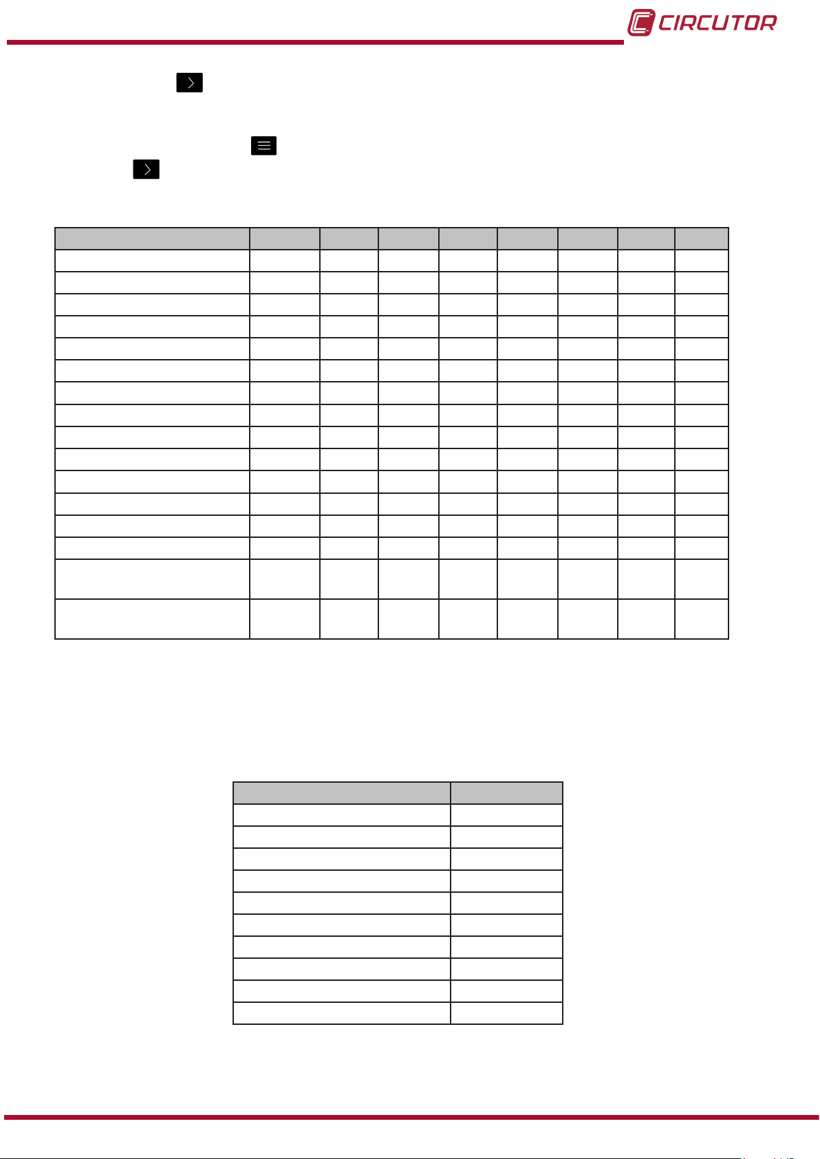
Table 12: Parameter codes used to program the outputs�
Parameter Phase Code Phase Code Phase Code Phase Code
Phase-Neutral Voltage L1 01 L2 09 L3 17 - Current L1 02 L2 10 L3 18 - Active power L1 03 L2 11 L3 19 III 25
Inductive Reactive Power L1 04 L2 12 L3 20 III 26
Capacitive Reactive Power L1 05 L2 13 L3 21 III 27
Apparent power L1 06 L2 14 L3 22 III 28
Power factor L1 07 L2 15 L3 23 III 29
Cosine φ L1 08 L2 16 L3 24 III 30
% THD V L1 36 L2 37 L3 38 - % THD A L1 39 L2 40 L3 41 - Phase-Phase Voltage L1/2 32 L2/3 33 L3/1 34 - Frequency - 31 - - - - - Neutral current - 35 - - - - - Maximum current demand L1 45 L2 46 L3 47 III 44
Active Power Maximum
Demand
Apparent Power Maximum
Demand
- - - - - - III 42
- - - - - - III 43
In addition, there are some parameters (Table 13) that refer to the three phases at the same
time (OR function). If you have selected one of these variables, the alarm will be activated when
any of the three phases meets the programmed conditions.
Table 13:Multiple parameter codes for alarm programming�
Types of parameters Code
Phase-Neutral Voltage 200
Current 201
Active power 202
Inductive Reactive Power 203
Capacitive Reactive Power 204
Power factor 205
Phase-Phase Voltage 206
% THD V 207
% THD A 208
Apparent Power 209
Instruction Manual
49
Page 50

CVM-C10
Programming the maximum value
The maximum value: the alarm is activated when this value is
exceeded.
Press key
for 3 seconds to edit the maximum value selection.
The prog icon will be displayed on the bottom of the screen.
To enter or modify the value, press the
key repeatedly,
increasing the value of the ashing digit.
When the desired value is shown on the screen, move onto the next digit by pressing the key
to modify the other values.
In the case of some parameters (Table 14), you can modify the position of the decimal point.
To do so, press key after modifying the last digit and the decimal point will start ashing.
Press key repeatedly to modify the position of the decimal point.
To validate the data, press for 3 seconds and the prog icon will disappear from the display.
Press key to access the next programming step
Table 14:Decimal point and units of the alarm parameters�
Types of parameters Units Decimal point
2000 V
Voltage
Current A Programmable
Frequency Hz Fixed
Power kW Programmable
Power factor PF Fixed
Cosine φ φ Fixed
Maximum current demand A Programmable
Maximum power demand kW Programmable
THD % Fixed
200.0 V
20.00 kV
2.000 kV
Programmable
50
Programming the minimum value
The minimum value: the alarm is activated below this value.
Press key
for 3 seconds to edit the minimum value selection.
The prog icon will be displayed on the bottom of the screen.
To enter or modify the value, press the
increasing the value of the ashing digit.
key repeatedly,
When the desired value is shown on the screen, move onto the next digit by pressing the key
to modify the other values.
Instruction Manual
Page 51
CVM-C10
In the case of some parameters (Table 14) you can modify the position of the decimal point.
To do so, press key after modifying the last digit and the decimal point will start ashing.
Press key repeatedly to modify the position of the decimal point.
To validate the data, press for 3 seconds and the prog icon will disappear from the display.
Press key to access the next programming step.
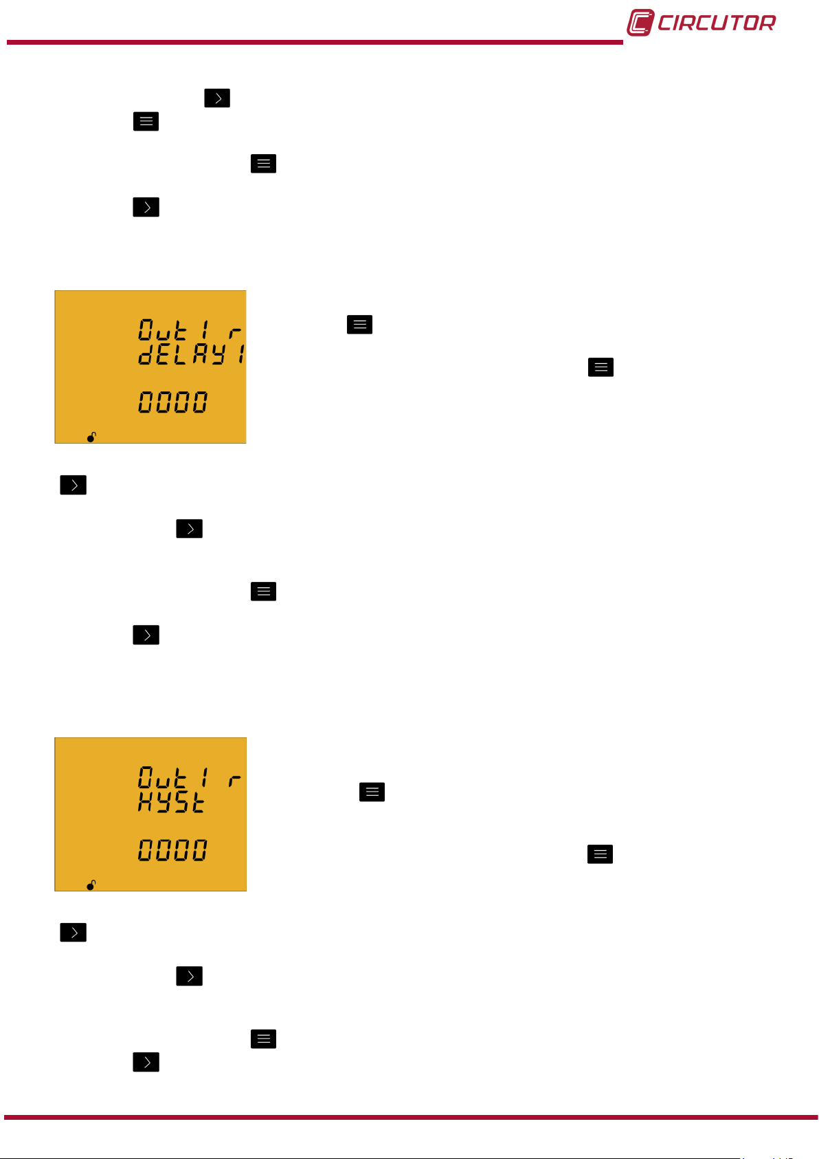
Programming the connection time delay
The alarm connection delay is programmed on this screen in
seconds.
Press key
for 3 seconds to edit the delay selection. The prog
icon will be displayed on the bottom of the screen.
To enter or modify the value, press the
key repeatedly,
increasing the value of the ashing digit.
When the desired value is shown on the screen, move onto the next digit by pressing the key
to modify the other values.
If you press the key after changing the last digit, it will jump back to the rst digit so you
can modify the previously programmed values again.
To validate the data, press for 3 seconds and the prog icon will disappear from the display.
Press key to access the next programming step.
Programming the hysteresis value
The hysteresis value, i.e., difference between the alarm
connection and disconnection value, in %, is programmed on
this screen.
Press key
for 3 seconds to edit the hysteresis value
selection. The prog icon will be displayed on the bottom of the
screen.
To enter or modify the value, press the
key repeatedly,
increasing the value of the ashing digit.
When the desired value is shown on the screen, move onto the next digit by pressing the key
to modify the other values.
If you press the key after changing the last digit, it will jump back to the rst digit so you
can modify the previously programmed values again.
To validate the data, press for 3 seconds and the prog icon will disappear from the display.
Press key to access the next programming step.
Instruction Manual
51
Page 52

CVM-C10
Programming the latch
The interlocking is selected on this screen, i.e., if the alarm is
interlocked after it has been tripped, even when the condition that
triggered it has disappeared.
Press key
for 3 seconds to edit the selection. The prog icon
will be displayed on the bottom of the screen.
Press key
to browse the two options (Yes and No).
To validate the data, press for 3 seconds and the prog icon will disappear from the display.
Press key to access the next programming step.
Note: If the unit is reset, the status of alarms is deleted and all alarms will return to the
programmed standby status, provided that the condition that triggered them has been resolved.
Programming the time delay 2
The alarm disconnection delay is programmed on this screen in
seconds.
Press key
for 3 seconds to edit the maximum value selection.
The prog icon will be displayed on the bottom of the screen.
To enter or modify the value, press the
key repeatedly,
increasing the value of the ashing digit.
When the desired value is shown on the screen, move onto the next digit by pressing the key
to modify the other values.
If you press the key after changing the last digit, it will jump back to the rst digit so you
can modify the previously programmed values again.
To validate the data, press for 3 seconds and the prog icon will disappear from the display.
Press key to access the next programming step.
52
Instruction Manual
Page 53
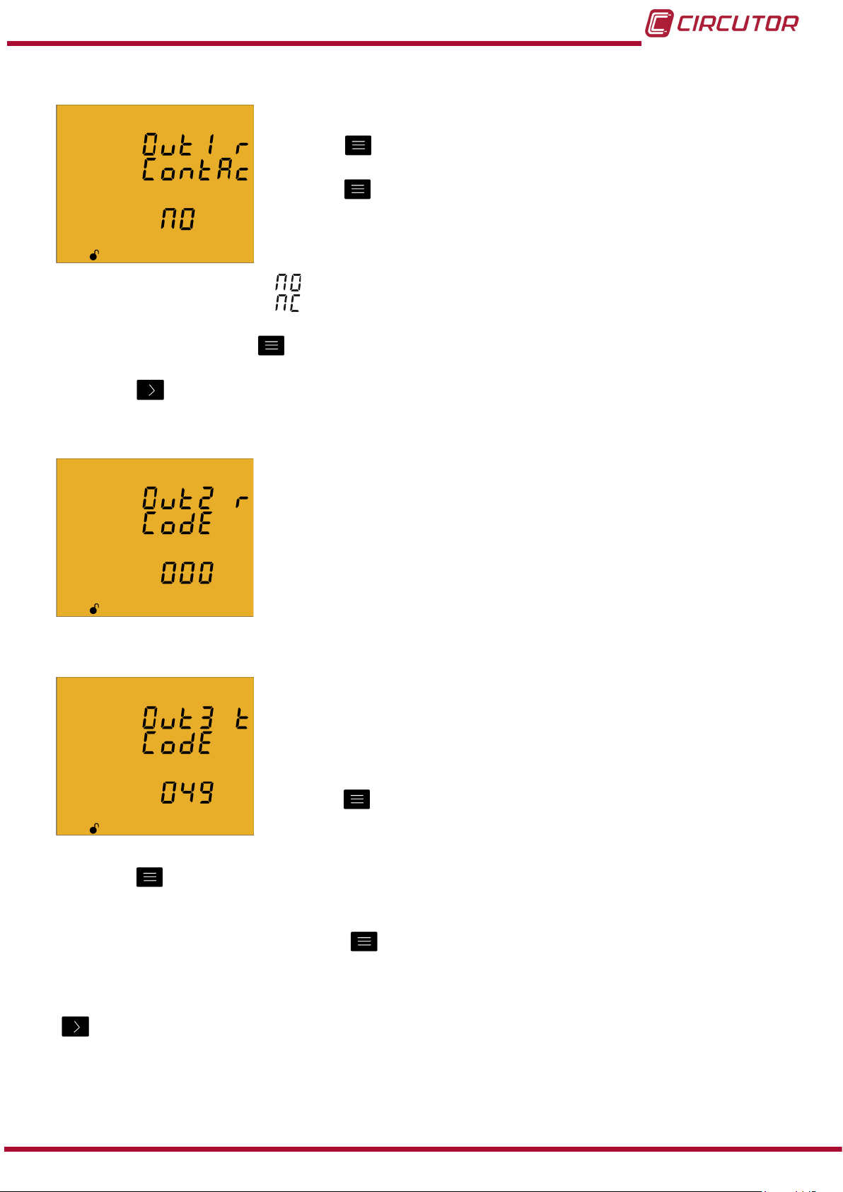
CVM-C10
Programming the contact status
The status of relay contacts is selected on this screen.
Press key
for 3 seconds to edit the selection. The prog icon
will be displayed on the bottom of the screen.
Press key
to browse the two options:
Normally open contact.
Normally closed contact.
To validate the data, press for 3 seconds and the prog icon will disappear from the display.
Press key to access the next programming step
4�9�23� Programming alarm 2 (Relay 2)
The values for alarm relay 2 are programmed on this screen.
They are programmed as in the case of alarm relay 1, see
“4.9.22. Programming alarm 1 (Relay 1)”
4�9�24� Programming alarm 3 (Digital output T1)
All values for digital output T1 are programmed on this screen.
The variable code is selected on this screen, depending on Table
15,
which will control digital output T1.
Press key
for 3 seconds to edit the code selection. The prog
icon will be displayed on the bottom of the screen.
Press key for 3 seconds to edit the code selection. The prog icon will be displayed on the
bottom of the screen.
To enter or modify the value, press the key repeatedly, increasing the value of the ashing
digit.
When the desired value is shown on the screen, move onto the next digit by pressing the key
to modify the other values.
When you enter the code of a variable on the display, the symbols for that variable will be
activated.
Set the value to 00 if you do not wish to program a variable.
Instruction Manual
53
Page 54
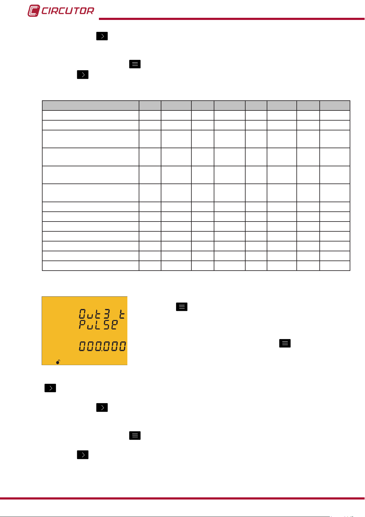
CVM-C10
If you press the key after changing the last digit, it will jump back to the rst digit so you
can modify the previously programmed values again.
To validate the data, press for 3 seconds and the prog icon will disappear from the display.
Press key to access the next programming step
Table 15: Parameter codes used to program digital outputs�
Parameter
Consumed Active Energy T1 49 T2 70 T3 91 total 112
Generated Active Energy T1 59 T2 80 T3 101 total 122
Consumed Inductive Reactive
Energy
Generated Inductive Reactive
Energy
Consumed Capacitive Reac-
tive Energy
Generated Capacitive Reac-
tive Energy
Consumed Apparent Energy T1 55 T2 76 T3 97 total 118
Generated Apparent Energy T1 65 T2 86 T3 107 total 128
Consumed CO2 Emissions T1 56 T2 77 T3 98 total 119
Generated CO2 Emissions T1 66 T2 87 T3 108 total 129
Consumption Cost T1 57 T2 78 T3 99 total 120
Generation Cost T1 67 T2 88 T3 109 total 130
No. of hours T1 68 T2 T3 110 total 131
Tariff
T1 51 T2 72 T3 93 total 114
T1 61 T2 82 T3 103 total 124
T1 53 T2 74 T3 95 total 116
T1 63 T2 84 T3 105 total 126
Code
Tariff
Code
Tariff
Code
Tariff
Code
Programming kilowatts per pulse
Press key for 3 seconds to edit the kilowatts per pulse
selection. The prog icon will be displayed on the bottom of the
screen.
To enter or modify the value, press the
key repeatedly,
increasing the value of the ashing digit.
When the desired value is shown on the screen, move onto the next digit by pressing the key
to modify the other values.
If you press the key after changing the last digit, it will jump back to the rst digit so you
can modify the previously programmed values again.
To validate the data, press for 3 seconds and the prog icon will disappear from the display.
Press key to access the next programming step.
54
The programmed value will be deleted if the entered value is higher than the maximum
programming value.
Instruction Manual
Page 55

CVM-C10
Maximum programming value: 999.999 KWh
Minimum programming value: 000.001 KWh
Example: To program 500 Wh per pulse: 000.500
To program 1.5 kWh per pulse: 001.500
Programming the pulse width
The width of the pulse is selected on this screen in ms.
Press key
for 3 seconds to edit the pulse width selection. The
prog icon will be displayed on the bottom of the screen.
To enter or modify the value, press the
key repeatedly,
increasing the value of the ashing digit.
When the desired value is shown on the screen, move onto the next digit by pressing the key
to modify the other values.
If you press the key after changing the last digit, it will jump back to the rst digit so you
can modify the previously programmed values again.
To validate the data, press for 3 seconds and the prog icon will disappear from the display.
Press key to access the next programming step.
The programmed value will be deleted if the entered value is higher than the maximum
programming value.
Maximum programming value: 500 ms.
Minimum programming value: 30 ms.
4�9�25� Programming alarm 4 (Digital output T2)
All values for digital output T2 are programmed on this screen.
They are programmed as in the case of digital output T1, see
“4.9.24. Programming alarm 3 (Digital output T1)”
Instruction Manual
55
Page 56

4�9�26� Operating mode of digital input 1
The function of digital input 1 is selected on this screen.
CVM-C10
Press key
for 3 seconds to edit the function selection. The
prog icon will be displayed on the bottom of the screen.
Press key
to browse the two options:
Logic input
Tariff selection.
To validate the data, press for 3 seconds and the prog icon will disappear from the display.
Press key to access the next programming step.
4�9�27� Operating mode of digital input 2
The function of digital input 2 is selected on this screen.
Press key
for 3 seconds to edit the function selection. The
prog icon will be displayed on the bottom of the screen.
Press key
to browse the two options:
Logic input
Tariff selection.
To validate the data, press for 3 seconds and the prog icon will disappear from the display.
Press key to access the next programming step.
4�9�28� RS-485 communications: Protocol
The RS-485 communications protocol is selected on this screen.
Press the
key for 3 seconds to edit the function selection.
The prog icon will be displayed on the bottom of the screen.
Press key
to browse the two options:
Modbus
BACnet
To validate the data, press for 3 seconds and the prog icon will disappear from the display.
56
Press key to access the next programming step.
Note: The unit will restart after exiting the setup menu if the RS-485 communications
parameters have been modied.
Instruction Manual
Page 57
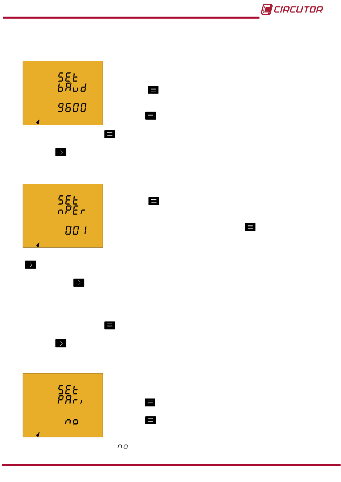
CVM-C10
4�9�28�1 Modbus protocol
Transmission speed
The transmission speed of modbus communications is
programmed on this screen.
Press key
for 3 seconds to edit the transmission speed
selection. The prog icon will be displayed on the bottom of the
screen.
Press key
to browse the two options: 9600 or 19200.
To validate the data, press for 3 seconds and the prog icon will disappear from the display.
Press key to access the next programming step.
Peripheral number
The peripheral number is programmed on this screen.
Press key
for 3 seconds to edit the peripheral number
selection. The prog icon will be displayed on the bottom of the
screen.
To enter or modify the value, press the
key repeatedly,
increasing the value of the ashing digit.
When the desired value is shown on the screen, move onto the next digit by pressing the key
to modify the other values.
If you press the key after changing the last digit, it will jump back to the rst digit so you
can modify the previously programmed values again.
The peripheral number ranges from 0 to 255.
To validate the data, press for 3 seconds and the prog icon will disappear from the display.
Press key to access the next programming step.
Parity
The type of parity of Modbus communications is selected on this
screen.
Press key
for 3 seconds to edit the parity type selection. The
prog icon will be displayed on the bottom of the screen.
Press key
to browse the options:
no parity
Instruction Manual
57
Page 58

CVM-C10
even parity.
odd parity.
To validate the data, press for 3 seconds and the prog icon will disappear from the display.
Press key to access the next programming step.
Number of data bits
The number of data bits of Modbus communications are
programmed on this screen.
Press key
for 3 seconds to edit the bit number selection. The
prog icon will be displayed on the bottom of the screen.
Press key
to browse the two options: 7 or 8 bits.
To validate the data, press for 3 seconds and the prog icon will disappear from the display.
Press key to access the next programming step.
Number of Stop bits
The number of Stop bits of Modbus communications are
programmed on this screen.
Press key
for 3 seconds to edit the Stop bits number
selection. The prog icon will be displayed on the bottom of the
screen.
Press key
to browse the options: 1 or 2 bits.
To validate the data, press for 3 seconds and the prog icon will disappear from the display.
58
Press key to access the next programming step.
4�9�28�2 BACnet protocol
Note: Protocol available in units with version 3.00 or higher.
Transmission speed
The transmission speed of BACnet communications is
programmed on this screen.
Press key
for 3 seconds to edit the transmission speed
selection. The prog icon will be displayed on the bottom of the
screen.
Press key
to browse the two options: 9600 or 19200.
Instruction Manual
Page 59

CVM-C10
To validate the data, press for 3 seconds and the prog icon will disappear from the display.
Press key to access the next programming step.
Device ID
The device ID is programmed on this screen.
Press the
key for 3 seconds to edit the value. The prog icon
will be displayed on the bottom of the screen.
To enter or modify the value, press the
key repeatedly,
increasing the value of the ashing digit.
When the desired value is shown on the screen, press the key to go to the next digit and
modify the other values.
If you press the key after changing the last digit, it will jump back to the rst digit so you
can modify the previously programmed values again.
Maximum programming value: 999999.
Minimum programming value: 0.
To validate the data, press for 3 seconds and the prog icon will disappear from the display.
Press key to access the next programming step.
MAC
The MAC address is programmed on this screen.
Press the
key for 3 seconds to edit the value. The prog icon
will be displayed on the bottom of the screen.
To enter or modify the value, press the
key repeatedly,
increasing the value of the ashing digit.
When the desired value is shown on the screen, press the key to go to the next digit and
modify the other values.
If you press the key after changing the last digit, it will jump back to the rst digit so you
can modify the previously programmed values again.
Maximum programming value: 255.
Minimum programming value: 0.
To validate the data, press for 3 seconds and the prog icon will disappear from the display.
Instruction Manual
59
Page 60

Press key to access the next programming step.
4�9�29� Locking the programming
This screen is for protecting the data configured in the
programming menu.
CVM-C10
Press key
for 3 seconds to edit the locking/unlocking
selection. The prog icon will be displayed on the bottom of the
screen.
Press key
to browse the two options:
When you enter the programming menu you can view and modify the programming. Icon
on the display indicates the permanently locked status.
When you enter the programming you can view the programming but not modify it. Icon
indicates the locking status. Enter the password to modify the programming values.
To validate the data, press for 3 seconds and the prog icon will disappear from the display.
Press the key to enter the password for locking and unlocking the programming:
On this screen you enter the password for locking and unlocking
the programming.
Press key
for 3 seconds to edit the password selection. The
prog icon will be displayed on the bottom of the screen.
To enter or modify the value, press the
key repeatedly,
increasing the value of the ashing digit.
When the desired value is shown on the screen, move onto the next digit by pressing the key
to modify the other values.
If you press the key after changing the last digit, it will jump back to the rst digit so you
can modify the previously programmed values again.
To validate the data, press for 3 seconds and the prog icon will disappear from the display.
Default password: 1234.
This value may only be modified through communications. See “4.10.3.6.16. Password
conguration.”
Press the key to exit the setup menu.
Note: The unit will restart after exiting the setup menu if the RS-485 communications
parameters have been modied.
60
Instruction Manual
Page 61

CVM-C10
4.10.- COMMUNICATIONS
The CVM-C10 units have one RS-485 communications port.
The unit has as standard two communications protocols: MODBUS RTU ® and BACnet.
The protocol and conguration parameters are selected in the setup menu. (“4.9.28. RS-485
communications: Protocol”)
Note: BACnet protocol available in units with version 3.00 or higher.
4�10�1� CONNECTIONS
The RS -485 cable must be wired with twisted pair cable with mesh shield (minimum 3 wires),
with a maximum distance between the CVM-C10 and the master unit of 1200 metres.
A maximum of 32 CVM-C10 units can be connected to this bus.
Use an intelligent RS-232 to RS-485 network protocol converter to establish the
communications with the master unit.
POWER SUPPLY
OUTPUTS
S0-
Rc R2 R1 Tc T2 T1
PC
RS-232 / USB / Ethernet / Profibus ...
RS-232
USB
Ethernet
Profibus
...
RS-485
RS-485
A ( + )
B ( - )
S0+ S0+
INPUTS
RS485
A(+) B(-)
I1 I2
GND
S
OUTPUTS
S0-
S0+ S0+
INPUTS
RS485
A(+) B(-)
POWER SUPPLY
Rc R2 R1 Tc T2 T1
I1 I2
GND
Instruction Manual
Ph-NPh-Ph
~
300V
~
520V
L3L2VL1
V
NV
P1 P2
S1 S2
P1 P2
P1 P2
L3
L1
L2
S1 S2
S1 S2
Ph-NPh-Ph
~
300V
~
520V
L3L2VL1
V
NV
P1 P2
S1 S2
P1 P2
P1 P2
L3
L1
L2
S1 S2
S1 S2
Figure 25: RS-485 Connection diagram�
61
Page 62

CVM-C10
4�10�2� PROTOCOL
In the Modbus protocol, the CVM-C10 unit uses the RTU (Remote Terminal Unit) mode.
The Modbus functions implemented in the unit are as follows:
0x03 and 0x04 function. Reading integer logs.
0x05 function. Writing a relay.
0x10 function. Writing multiple logs.
4�10�2�1 Ejemplo de lectura : Función 0x04�
Question: Instantaneous value of the phase voltage of L1
Address Function Initial log No� of logs CRC
0A 04 0000 0002 70B0
Address: 0A, Peripheral number: 10 in decimals.
Function: 04, Read function.
Initial Log: 0000, log on which the reading will start.
No� of logs: 0002, number of logs read.
CRC: 70B0, CRC Character.
Response:
Address
0A 04 04 0000 084D 8621
Func-
tion
No� of
Bytes
Log No� 1 Log No� 2 CRC
Address: 0A, Responding peripheral number: 10 in decimals.
Function: 04, Read function.
No� of bytes: 04, No. of bytes received.
Log: 0000084D, value of the phase voltage of L1: VL1 x 10 : 212.5V
CRC: 8621, CRC Character.
Note : Every Modbus frame has a maximum limit of 20 variables (40 logs).
4�10�2�2� Writing example: 0x05 function.
62
Question: Deleting maximum and minimum values.
Address Function Initial log Value CRC
0A 05 0834 FF00 CEEF
Address: 0A, Peripheral number: 10 in decimal.
Function: 05, Read function.
Initial Log: 0834, log of the parameter for deleting maximum and minimum values.
Value: FF00, we indicate that we want to delete the maximum and minimum values.
CRC: CEEF, CRC character.
Instruction Manual
Page 63

CVM-C10
Response:
Address Function Initial log Value CRC
0A 05 0834 FF00 CEEF
4�10�3� COMANDOS MODBUS
4�10�3�1� Measurement variables�
All the adresses of Modbus memory are in Hexadecimal.
For these variables is implemented the Function 0x03 and 0x04�
Table 16: Modbus memory map (Table 1)
Parameter Symbol Instantaneous Maximum Minimum Units
L1 Phase voltage V 1 00-01 106-107 164-165 V x 10
L1 Current A 1 02-03 108-109 166-167 mA
L1 Active Power kW 1 04-05 10A-10B 168-169 W
L1 Inductive Power kvarL 1 06-07 10C-10D 16A-16B var
L1 Capacitive Power kvarC 1 08-09 10E-10F 16C-16D var
L1 Apparent Power kVA 1 0A-0B 110-111 16E-16F VA
L1 Power Factor PF 1 0C-0D 112-113 170-171 x 100
Cos φ L1 Cos φ 1 0E-0F 114-115 172-173 x 100
L2 Phase voltage V 2 10-11 116-117 174-175 V x 10
L2 Current A 2 12-13 118-119 176-177 mA
L2 Active Power kW 2 14-15 11A-11B 178-179 W
L2 Inductive Power kvarL 2 16-17 11C-11D 17A-17B var
L2 Capacitive Power kvarC 2 18-19 11E-11F 17C-17D var
L2 Apparent Power kVA 2 1A-1B 120-121 17E-17F VA
L2 Power Factor PF 2 1C-1D 122-123 180-181 x 100
Cos φ L2 Cos φ 2 1E-1F 124-125 182-183 x 100
L3 Phase voltage V 3 20-21 126-127 184-185 V x 10
L3 Current A 3 22-23 128-129 186-187 mA
L3 Active Power kW 3 24-25 12A-12B 188-189 W
L3 Inductive Power kvarL 3 26-27 12C-12D 18A-18B var
L3 Capacitive Power kvarC 3 28-29 12E-12F 18C-18D var
L3 Apparent Power kVA 3 2A-2B 130-131 18E-18F VA
L3 Power Factor PF 3 2C-2D 132-133 190-191 x 100
Cos φ L3 Cos φ 3 2E-2F 134-135 192-193 x 100
Active Three-phase Power kW III 30-31 136-137 194-195 W
Inductive Three-phase power kvarL III 32-33 138-139 196-197 var
Capacitive Three-phase Power kvarC III 34-35 13A-13B 198-199 var
Apparent three-phase power kVA III 36-37 13C-13D 19A-19B VA
Three-phase Power Factor PF III 38-39 13E-13F 19C-19D x100
Three-phase Cos φ Cos φ III 3A-3B 140-141 19E-19F x100
L1 Frequency Hz 3C-3D 142-143 1A0-1A1 Hz x100
L1-L2 Voltage V12 3E-3F 144-145 1A2-1A3 V x 10
L2-L3 Voltage V23 40-41 146-147 1A4-1A5 V x 10
L3-L1 Voltage V31 42-43 148-149 1A6-1A7 V x 10
Instruction Manual
63
Page 64

CVM-C10
Table 16 ( Continuation ) : Modbus memory map (Table 1)
Parameter Symbol Instantaneous Maximum Minimum Units
Neutral Current N A N 44-45 14A-14B 1A8-1A9 mA
L1 voltage % THD %THDV1 46-47 14C-14D 1AA-1AB % x 10
L2 voltage % THD %THDV2 48-49 14E-14F 1AC-1AD % x 10
L3 voltage % THD %THDV3 4A-4B 150-151 1AE-1AF % x 10
L1 current % THD %THDI1 4C-4D 152-153 1B0-1B1 % x 10
L2 current % THD %THDI2 4E-4F 154-155 1B2-1B3 % x 10
L3 current % THD %THDI3 50-51 156-157 1B4-1B5 % x 10
Maximum demand kW III Md (Pd) 52-53 158-159 - W
Maximum demand kVA III Md (Pd) 54-55 15A-15B - VA
Maximum demand I AVG Md (Pd) 56-57 15C-15D - mA
Maximum demand I L1 Md (Pd) 58-59 15E-15F - mA
Maximum demand I L2 Md (Pd) 5A-5B 160-161 - mA
Maximum demand I L3 Md (Pd) 5C-5D 162-163 - mA
4�10�3�2� Energy variables
All the adresses of Modbus memory are in Hexadecimal.
For these variables is implemented the Function 0x03 and 0x04�
Table 17: Modbus memory map (Table 2)
Parameter Symbol Tariff 1 Tariff 2 Tariff 3 Total Units
Consumed active energy kW) kWh III 5E-5F 88-89 B2-B3 DC-DD kWh
Consumed active energy (W) kWh III 60-61 8A-8B B4-B5 DE-DF Wh
Consumed inductive reactive energy
(kvarhL)
Consumed inductive reactive energy
(varhL)
Consumed capacitive reactive energy (kvarhC)
Consumed capacitive reactive energy (varhC)
Consumed apparent energy (kVAh) kVAh III 6A-6B 94-95 BE-BF E8-E9 kVAh
Consumed apparent energy (VAh) kVAh III 6C-6D 96-97 C0-C1 EA-EB VAh
Consumed CO2 emissions KgCO
Consumption cost $ 70-71 9A-9B C4-C5 EE-EF x10
Generated active energy (kW) kWh III 72-73 9C-9D C6-C7 F0-F1 kWh
Generated active energy (W) kWh III 74-75 9E-9F C8-C9 F2-F3 Wh
Generated inductive reactive energy
(kvarhL)
Generated inductive reactive energy
(varhL)
Generated capacitive reactive energy (kvarhC)
Generated capacitive reactive energy (varhC)
Generated apparent energy (kVAh) kVAh III 7E-7F A8-A9 D2-D3 FC-FD kVAh
Generated apparent energy (VAh) kVAh III 80-81 AA-AB D4-D5 FE-EF VAh
Generated CO2 emissions KgCO
kvarhL III 62-63 8C-8D B6-B7
kvarhL III 64-65 8E-8F B8-B9
kvarhC III 66-67 90-91 BA-BB
kvarhC III 68-69 92-93 BC-BD
2
6E-6F 98-99 C2-C3 EC-ED x10
kvarhL III 76-77 A0-A1 CA-CB
kvarhL III 78-79 A2-A3 CC-CD
kvarhC III 7A-7B A4-A5 CE-CF
kvarhC III 7C-7D A6-A7 D0-D1
2
82-83 AC-AD D6-D7 100-101 x10
E0-E1 kvarh
E2-E3 varh
E4-E5 kvarh
E6-E7 varh
F4-F5 kvarh
F6-F7 varh
F8-F9 kvarh
FA-FB varh
64
Instruction Manual
Page 65
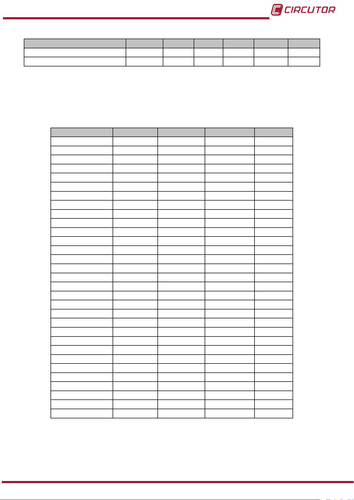
CVM-C10
Table 17 ( Continuation ) : Modbus memory map (Table 2)
Parameter Symbol Tariff 1 Tariff 2 Tariff 3 Total Units
Generation Cost $ 84-85 AE-AF D8-D9 102-103 x10
Hours per tariff Hours 86-87 B0-B1 DA-DB 104-105 sec
4�10�3�3� Voltage and current harmonics�
All the adresses of Modbus memory are in Hexadecimal.
For these variables is implemented the Function 0x03 and 0x04�
Table 18:Modbus memory map (Table 3)�
Parameter L1 Voltage L2 Voltage L3 Voltage Units
Fundamental Harm. A28-A29 A48-A49 A68-A69 V x 10
2nd Order harmonic A2A A4A A6A % x 10
3rd Order harmonic A2B A4B A6B % x 10
4th Order harmonic A2C A4C A6C % x 10
5th Order harmonic A2D A4D A6D % x 10
6th Order harmonic A2E A4E A6E % x 10
7th Order harmonic A2F A4F A6F % x 10
8th Order harmonic A30 A50 A70 % x 10
9th Order harmonic A31 A51 A71 % x 10
10th Order harmonic A32 A52 A72 % x 10
11th Order harmonic A33 A53 A73 % x 10
12th Order harmonic A34 A54 A74 % x 10
13th Order harmonic A35 A55 A75 % x 10
14th Order harmonic A36 A56 A76 % x 10
15th Order harmonic A37 A57 A77 % x 10
16th Order harmonic A38 A58 A78 % x 10
17th Order harmonic A39 A59 A79 % x 10
18th Order harmonic A3A A5A A7A % x 10
19th Order harmonic A3B A5B A7B % x 10
20th Order harmonic A3C A5C A7C % x 10
21st Order harmonic A3D A5D A7D % x 10
22nd Order harmonic A3E A5E A7E % x 10
23rd Order harmonic A3F A5F A7F % x 10
24th Order harmonic A40 A60 A80 % x 10
25th Order harmonic A41 A61 A81 % x 10
26th Order harmonic A42 A62 A82 % x 10
27th Order harmonic A43 A63 A83 % x 10
28th Order harmonic A44 A64 A84 % x 10
29th Order harmonic A45 A65 A85 % x 10
30th Order harmonic A46 A66 A86 % x 10
31st Order harmonic A47 A67 A87 % x 10
Instruction Manual
65
Page 66

Table 19:Modbus memory map (Table 4)�
Parameter L1 Current L2 Current L3 Current Units
Fundamental Harm. A88-A89 AA8-AA9 AC8-AC9 mA x 10
2nd Order harmonic A8A AAA AAC % x 10
3rd Order harmonic A8B AAB ACB % x 10
4th Order harmonic A8C AAC ADC % x 10
5th Order harmonic A8D AAD ACD % x 10
6th Order harmonic A8E AAE ACE % x 10
7th Order harmonic A8F AAF ACF % x 10
8th Order harmonic A90 AB0 AD0 % x 10
9th Order harmonic A91 AB1 AD1 % x 10
10th Order harmonic A92 AB2 AD2 % x 10
11th Order harmonic A93 AB3 AD3 % x 10
12th Order harmonic A94 AB4 AD4 % x 10
13th Order harmonic A95 AB5 AD5 % x 10
14th Order harmonic A96 AB6 AD6 % x 10
15th Order harmonic A97 AB7 AD7 % x 10
16th Order harmonic A98 AB8 AD8 % x 10
17th Order harmonic A99 AB9 AD9 % x 10
18th Order harmonic A9A ABA ADA % x 10
19th Order harmonic A9B ABB ADB % x 10
20th Order harmonic A9C ABC ADC % x 10
21st Order harmonic A9D ABD ADD % x 10
22nd Order harmonic A9E ABE ADE % x 10
23rd Order harmonic A9F ABF ADF % x 10
24th Order harmonic AA0 AC0 AE0 % x 10
25th Order harmonic AA1 AC1 AE1 % x 10
26th Order harmonic AA2 AC2 AE2 % x 10
27th Order harmonic AA3 AC3 AE3 % x 10
28th Order harmonic AA4 AC4 AE4 % x 10
29th Order harmonic AA5 AC5 AE4 % x 10
30th Order harmonic AA6 AC6 AE6 % x 10
31st Order harmonic AA7 AC7 AE7 % x 10
CVM-C10
66
4�10�3�4� Deleting parameters�
All the Modbus map addresses are hexadecimal.
The 0x05 function is implemented for these variables.
Table 20:Modbus memory map: Deleting parameters�
Parameters
Deleting energies 834 FF00
Deleting maximum and minimum values 838 FF00
Starting maximum demand 839 FF00
Deleting the hour counters (All tariffs) 83D FF00
Deleting the maximum value of the maximum demand 83F FF00
Deleting energies, maximum demand and maximum and
minimum values
Address Valid data margin
848 FF00
Instruction Manual
Page 67

CVM-C10
4�10�3�5� Power status�
TAll the Modbus map addresses are hexadecimal.
The 0x04 function is implemented for this variable.
This variable indicates the quadrant in which the unit is operating.
Table 21:Modbus memory map: Power status
Power status
Variable Address Default value
Power status 7D1 -
The variable format is shown in Table 22:
Table 22:Variable format: Power status�
Bit 7 Bit 6 Bit 5 Bit 4 Bit 3 Bit 2 Bit 1 Bit 0
0 0 0 0 1: Capacitive 1: Inductive 1: Generated 1: Consumed
4�10�3�6� Unit conguration variables.
All the Modbus map addresses are hexadecimal.
The 0x04 and 0x10 functions are implemented for this variable.
The unit’s Modbus function does not check whether the variables recorded are within the
correct margins, they are only checked when they are read from the EEPROM. So if any
parameter is recorded with an incorrect value the unit will be congured with its default value.
The Modbus conguration will not take effect until the unit is reset.
4�10�3�6�1� Transformation ratios�
Table 23:Modbus memory map: Transformation ratios�
Transformation ratios
Configuration variable
Voltage primary 2710 - 2711 1 - 599999 1
Voltage secondary 2712 1 - 999 1
Current primary 2713 1 - 10000 5
Current secondary 2714
(1)
All variables must be programmed at the same time.
(2)
Voltage ratio x Current ratio < 600000.
(1) (2)
Address Valid data margin
1: .../1A
5: ../5 A
Default
value
5
Note: The ratio is between the primary and the secondary.
Instruction Manual
67
Page 68

4�10�3�6�2� Neutral current transformation ratios (CVM-C10-ITF-IN)�
Table 24:Modbus memory map: Neutral current transformation ratios�
Transformation ratios
Configuration variable
(1)
Address Valid data margin
Default
Neutral current primary 271A 1 - 10000 5
Neutral current secondary 271B
(1)
All variables must be programmed at the same time.
1: .../1A
5: ../5 A
4�10�3�6�3� Number of quadrants
Table 25:Modbus memory map: Number of quadrants
Maximum demand
Configuration variable Address Valid data margin
Number of quadrants 2B64
0: 4 quadrants
1: 2 quadrants
Default
value
0
CVM-C10
value
5
4�10�3�6�4� Type of installation
Table 26:Modbus memory map: Type of installation
Type of installation
Configuration variable Address Valid data margin
0: Three-phase network with 4 wires�
1: Three-phase network with 3 wires.
2: Three-phase network with 3 wires, Aron.
Type of installation 2B5C
3: Two-phase network with 3 wires.
4: Single-phase network with 2 wires, phase-
to-phase.
5: Single-phase network with 2 wires, phase-
to-neutral.
4�10�3�6�5� Maximum demand
Table 27:Modbus memory map: Maximum demand
Maximum demand
Configuration variable Address Valid data margin
Integration period 274C 1 - 60 minutes 15
Default
value
0
Default
value
68
4�10�3�6�6� Operating prole
Table 28:Modbus memory map: Operating prole
Configuration variable Address Valid data margin
Operating prole 2B60
Operating profile
0: Analyzer
1: User
2: Electrical energy efciency, e
Default
value
0
3
Instruction Manual
Page 69

CVM-C10
4�10�3�6�7� Display backlight
Table 29:Modbus memory map: Backlight
Backlight
Configuration variable Address Valid data margin
Backlight 2B5E
0: Always lit
5 - 99 seconds
Default
value
0
4�10�3�6�8� Activating the harmonics display screen
Table 30:Modbus memory map: Display of harmonics
Display of harmonics
Configuration variable Address Valid data margin
Display of harmonics 2B62
0: No
1: Yes
Default
value
1
4�10�3�6�9� CO2 consumption and generation emissions�
Table 31:Modbus memory map: CO2 consumption and generation emissions�
CO2 emissions
Configuration variable
(1)(2)
Address Valid data margin
Tariff 1 consumption emissions ratio 2724 0 - 1�9999 0
Tariff 2 consumption emissions ratio 2725 0 - 1�9999 0
Tariff 3 consumption emissions ratio 2726 0 - 1�9999 0
Tariff 1 generation emissions ratio 2728 0 - 1�9999 0
Tariff 2 generation emissions ratio 2729 0 - 1�9999 0
Tariff 3 generation emissions ratio 272A 0 - 1�9999 0
(1)
All variables must be programmed at the same time.
(1)
They have 1 decimal place.
Default
value
4�10�3�6�10� Cost of energy consumption and generation�
Table 32:Modbus memory map: Cost of energy consumption and generation�
Cost per kWh
Configuration variable
Cost per kWh of tariff 1 consumption 272C 0 - 1�9999 0
Cost per kWh of tariff 2 consumption 272D 0 - 1�9999 0
Cost per kWh of tariff 3 consumption 272E 0 - 1�9999 0
Cost per kWh of tariff 1 generation 2730 0 - 1�9999 0
Cost per kWh of tariff 2 generation 2731 0 - 1�9999 0
Cost per kWh of tariff 3 generation 2732 0 - 1�9999 0
(1)
All variables must be programmed at the same time.
(1)
They have 1 decimal place.
(1)(2)
Address Valid data margin
Default
value
Instruction Manual
69
Page 70

4�10�3�6�11� Programming alarms 1 and 2 (Relays 1 and 2)
Table 33:Modbus memory map: Programming alarms 1 and 2�
Programming alarms 1 and 2
Configuration variable
Maximum value. 2AF8-2AF9 2B02-2B03 depending on the variable 0
Minimum value 2AFA-2AFB 2B04-2B05 depending on the variable 0
Variable code 2AFC 2B06 Table 12 0
Connection delay 2AFD 2B07 0 - 9999 seconds 0
Hysteresis: 2AFE 2B08 0 - 99 % 0
latch 2AFF 2B09
Disconnection delay 2B00 2B0A 0 - 9999 seconds 0
Contacts status 2B01 2B0B
Address
Relay 1 Relay 2
Valid data margin
0 : No
1: Yes
0 : Normally open
1: Normally closed
CVM-C10
Default
value
0
0
4�10�3�6�12� Programming alarms 3 and 4 (Digital outputs T1 and T2)
Table 34:Modbus memory map: Programming alarms 3 and 4�
Programming alarms 3 and 4
Configuration variable
Kilowatts per impulse 2B0C-2B0D 2B16-2B17 0.001 - 999.999 kWh 0
Variable code 2B10 2B1A Table 15 0
Pulse width 2B11 2B1B 10 - 500 ms 100 ms
Address
Relay 1 Relay 2
Valid data margin
Default
value
4�10�3�6�13� Digital inputs
Table 35:Modbus memory map: Conguration of digital inputs.
Configuration variable
Operating mode
(1)
If Input 1 is congured as a tariff and Input 2 is congured as a logic state (or vice versa) we
(1)
Input 1 Input 2
Address
2B66 2B67
Valid data margin
0: Tariff
1: Logic state
Default
value
0
will only have 2 tariffs.
We can also read the status of the digital inputs when they are in logic mode:
70
The 0x04 function is implemented for this variable.
Table 36:Modbus memory map: Status of the digital inputs (Logic state mode)
Status of digital inputs
Variable Address Default value
Status of digital inputs 4E20 -
The variable format is shown in Table 37:
Instruction Manual
Page 71
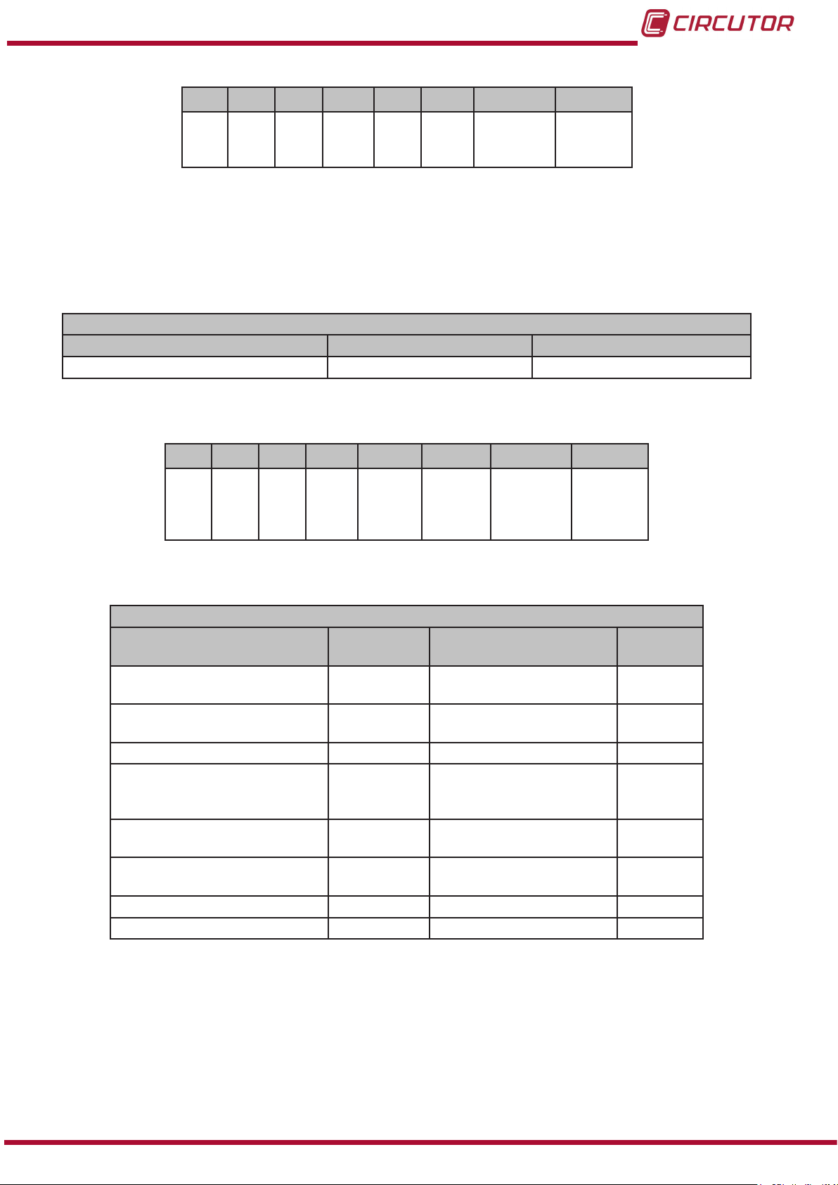
CVM-C10
Table 37:Variable format: Status of digital inputs�
Bit 7 Bit 6 Bit 5 Bit 4 Bit 3 Bit 2 Bit 1 Bit 0
0 0 0 0 0 0
Input 2
0: OFF
1: ON
Input 1
0: OFF
1: ON
4�10�3�6�14� Digital outputs
Reading the status of the digital outputs.
The 0x04 function is implemented for this variable.
Table 38:Modbus memory map: Status of the digital outputs
Status of the digital outputs
Variable Address Default value
Status of the digital outputs 4E21 -
The variable format is shown in Table 39:
Table 39:Variable format: Status of the digital outputs�
Bit 7 Bit 6 Bit 5 Bit 4 Bit 3 Bit 2 Bit 1 Bit 0
0 0 0 0
Output
4
0: OFF
1: ON
Output
3
0: OFF
1: ON
Output 2
0: OFF
1: ON
Output 1
0: OFF
1: ON
4�10�3�6�15� Communications
Table 40:Modbus memory map: Communications
Configuration variable Address Valid data margin
Protocol 2742
Modbus and BACnet:
Peripheral number
Modbus : Transmission speed 2744 0: 9600 - 1:19200 0
Modbus : Parity 2745
Modbus : Data bits 2746
Modbus : Stop bits 2747
BACnet: Device ID 2EE0- 2EE1 0- 999999 -
BAcnet: MAC 2EE2 0- 255 2
Communications
0 : Modbus
1: Bacnet
2743 0 - 255 1
0: No parity
1: Odd parity
2: Even parity
0 : 8 bits
1: 7 bits
0 : 1 stop bit
1: 2 stop bits
Default
value
0
0
0
0
Instruction Manual
71
Page 72

CVM-C10
4.10.3.6.16. Password conguration
These variables allow you to lock or unlock access to the programming menu, and also allow
you to change the password code. The password code may only be changed through this command.
The unit does not need you to enter the old password in order for it to record the new one; it
records the new one directly without any verication.
Table 41:Modbus memory map: Password conguration
Password
Configuration variable
Password value
Lock-Unlock 2B71
(1)
You must program all the variables at the same time.
(2)
The password value is read and written in hexadecimal.
(2)
(1)
Address Valid data margin Default value
2B70 0 - 9999 1234
0: Unlock
1: Lock
0
4�10�4� BACnet PROTOCOL
BACnet is a communications protocol for Building Automation and Control NETworks. This
protocol replaces the proprietary communications of each device, making it a set of common
communication rules that enables the complete integration of the building automation and
control devices of different manufacturers.
The unit features BACNet MS/TP communications, following the specifications of ANSI/
ASHRAE 135 (ISO 16484-5).
Using a RS485 connection, the unit can connect to a BACnet and include all of the objects and
services dened in the attached PICS map (Protocol Implementation Conformance Statement).
( “4.10.5. PICS MAP”)
The default speed is 9600 bps and the MAC is 2 (node number), and can be changed on the
conguration screen or by entering the BaudRate and MAC_Address variables. The identier
(Device_ID) can be changed on the conguration screen using the writing property over the
variable or through the Device_ID variable.
Another option is to overwrite the Object_Name in the Device object:
a) #Baud x – where x can be: 9600, 19200
b) #MAC x – where x can be: 0 ... 255
c) #ID x – where x can be: 0 ... 999999
72
For further information on the protocol: www.bacnet.org.
Instruction Manual
Page 73
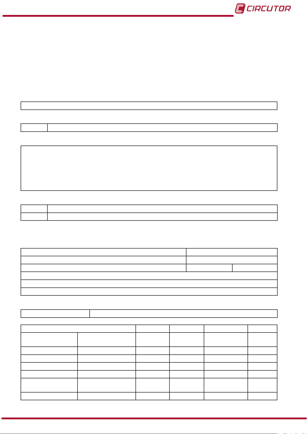
CVM-C10
4�10�5� MAPA PICS
PICS
Vendor Name: CIRCUTOR
Product Name: CVM-C10
Product Model Number: 0116
Application Software Version: 1.0
Firmware Revision: 0.7.1
BACnet Protocol Revision: 10
Product Description:
Electrical energy meter
BACnet Standardized Device Prole (Annex L)
x BACnet Application Specic Controller (B-ASC)
List all BACnet Interoperability Building supported (see Annex K in BACnet Addendum 135d):
DS-RP-B Read Property
DS-WP-B Write Propery
DS-RPM-B Read Property Multiple
DM-DDB-B Dynamic Device Binding
DM-DOB-B Dynamic Object Binding
DM-DCC-B Device Communication Control
DM-RD-B Reinitialize Device
Which of the following device binding methods does the product support? (check one or more)
x Recive Who-Is, send I-Am (BIBB DM-DDB-B)
x Recive Who-Has, send I-Have (BIBB DM-DOB-B)
Standard Object Types Supported:
Analog Input Object Type
1. Dynamically creatable using BACnet’s CreateObject service? No
2. Dynamically deleatable using BACnet’s DeleteObject service? No
3. List of optional properties supported: max_pres_value min_pres_value
4. Listo f all properties that are writable where not otherwisa required by this standard
5. List of proprietary properties:
6. List of any property value range restrictions:
Properly Identier
Object_Name max 32 characters
DESCRIPTION SYMBOL ID OBJECTS OBJECT NAME UNITS
Tensión fase-neutro
Corriente Current A 1 AI1 Ph1Current A
Potencia activa Active power kW 1 AI2 ActPwrPh1 kW
Potencia reactiva Reactive power kvar 1 AI3 ReactPwrPh1 kvar
Factor de potencia Power factor PF 1 AI4 PwrFactPh1 PF
Tensión fase-neutro Voltage phase to
Corriente Current A 2 AI6 Ph2Current A
Voltage phase to
neutral
neutral
V 1 AI0 Ph2NU1 V
V 2 AI5 Ph2NU2 V
Instruction Manual
73
Page 74

CVM-C10
DESCRIPTION SYMBOL ID OBJECTS OBJECT NAME UNITS
Potencia activa Active power kW 2 AI7 ActPwrPh2 kW
Potencia reactiva Reactive power kvar 2 AI8 ReactPwrPh2 kvar
Factor de potencia Power factor PF 2 AI9 PwrFactPh2 PF
Tensión fase-neutro Voltage phase to
neutral
Corriente Current A 3 AI11 Ph3Current A
Potencia activa Active power kW 3 AI12 ActPwrPh3 kW
Potencia reactiva Reactive power kvar 3 AI13 ReactPwrPh3 kvar
Factor de potencia Power factor PF 3 AI14 PwrFactPh3 PF
Potencia activa trifásica
Potencia inductiva
trifásica
Potencia capacitiva
trifásica
Cos φ trifásico Three phase cos φ Cos φ III AI18 Cosphi Cos φ
Factor de potencia
trifásico
Frecuencia (L2) Frequency Hz AI20 Frequency Hz
Tensión fase-fase Voltage phase to phase V12 AI21 Ph2PhU12 V
Tensión fase-fase Voltage phase to phase V23 AI22 Ph2PhU23 V
Tensión fase-fase Voltage phase to phase V31 AI23 Ph2PhU31 V
%THD V %THD V %THD V1 AI24 THDVal_U1 %THD
%THD V %THD V %THD V2 AI25 THDVal_U2 %THD
%THD V %THD V %THD V3 AI26 THDVal_U3 %THD
%THD A %THD A %THD A1 AI27 THDVal_I1 %THD
%THD A %THD A %THD A2 AI28 THDVal_I2 %THD
%THD A %THD A %THD A3 AI29 THDVal_I3 %THD
Energía activa Active energy kW•h III AI30 ActEnergy kW•h
Energía reactiva inductiva
Energía reactiva capacitiva
Energía Aparente
trifásica
Energía activa gene-
rada
Energía inductiva
generada
Energía capacitiva
generada
Energía aparente
generada
Corriente trifásica
(media)
Corriente de neutro Neutral current In AI39 NeutralCurrent In
Potencia aparente L1 Aparent power L1 kVA AI40 AppPwrPh1 k VA
Potencia aparente L2 Aparent power L2 kVA AI41 AppPwrPh2 k VA
Three phase active
power
Three phase reactive
inductive power
Three phase capacitive
inductive power
Three phase power
factor
Reactive inductive
energy
Reactive capacitive
energy
Three phase aparent
energy
Three phase generated
active energy
Three phase generated reactive inductive
energy
Three phase generated reactive capacitive
energy
Three phase generated
aparent energy
Three phase average
current
V 3 AI10 Ph2NU3 V
kW III AI15 ActPwOn3Ph kW
kvarL III AI16 InductPwOn3Ph kvarL
kvarC III AI17 CapPwOn3Ph kvarC
PFIII AI19 PwFactOn3Ph PF
kvarL•h III AI31 InductEnergy kvarL•h
kvarC•h III AI32 CapEnergy kvarC•h
kVA•h III AI33 AppEnergy kVA•h
kW•h III (-) AI34 ActEnergy_exp kW•h
kvarL•h III (-) AI35 IndEnergy_exp kvarL•h
kvarC•h III(-) AI36 CapEnergy_exp kvarC•h
kVA•h III (-) AI37 AppEnergy_exp kVA•h
I_AVG AI38 AvgValCurr3Ph I_AVG
74
Instruction Manual
Page 75

CVM-C10
DESCRIPTION SYMBOL ID OBJECTS OBJECT NAME UNITS
Potencia aparente L3 Aparent power L3 kVA AI42 AppPwrPh3 k VA
Potencia aparente
trifásica
Máxima demanda I1 Maximum demand I1 Md (A1) AI44 MaxDemand_A1 A
Máxima demanda I2 Maximum demand I2 Md(A2) AI45 MaxDemand_A2 A
Máxima demanda I3 Maximum demand I3 Md(A3) AI46 MaxDemand_A3 A
Máxima demanda A Maximum demand A A III AI47 MaxDemand_A A
Máxima demanda kW Maximum demand kW kW III AI48 MaxDemand_kW kW
Máxima demanda kVA Maximum demand kVA kVA III AI49
Three phase aparent
power
kVAIII AI43 AppPw3Ph kVA
MaxDemand_
kVA
kVA
Analog Value Object Type
1. Dynamically creatable using BACnet’s CreateObject service? No
2. Dynamically deleatable using BACnet’s DeleteObject service? No
3. List of optional properties supported:
4. List of all properties that are writable where not otherwise required by this standard
5. List of propietary properties:
Property Identier Property Datatype Meaning
5. List of object identiers and their meaning in this device
Object ID Object Name Description
AV1 MAC_Address MAC
AV2 BaudRate BAUD RATE
AV3 Device_ID DEVICE ID
Device Object Type
1. Dynamically creatable using BACnet’s CreateObject service? No
2. Dynamically deleatable using BACnet’s DeleteObject service? No
3. List of optional properties supported: Description, Protocolo_Conformance_Class
4. List of all properties that are writable where not otherwise required by this standard
Object_Name
Max_Master
Max_Info_Frames
Object_Identier
5. List of propietary properties:
5. List of any property value range restrictions
Property Identier Restrictions
Object_Name < 7 bytes
Object_Identier Device Type only
Number_Of_APDU_Retries 0-255
APDU_Timeout 0-65535 miliseconds
Vendor_Identier 0-65535
Data Link Layer Options (check all that supported):
X MS/TP master (Clause 9), baud rate(s): 9.6, 19.2kB/s
Character Sets Supported (check all that apply):
Indicating support for multiple character set does not imply that they can all be supported simultaneously.
X ANSI X3.4
Instruction Manual
75
Page 76

5�- TECHNICAL FEATURES
CVM-C10
AC Power supply
Rated voltage
85 ... 265 V ~
Frequency 50 ... 60 Hz
Consumption 4 ... 6 VA
Installation category CAT III 300 V
DC Power supply
Rated voltage 95 ... 300 V 20 ... 120 V
Consumption 2 ... 6 W 3.5 ... 3 W
Installation category CAT III 300 V
(1)
Only available for references M559110050000, M559210050000, M559210050V00 and M5594200500000.
Voltage measurement circuit
Rated voltage (Un) 300 V Ph-N, 520 V Ph-Ph
Voltage measurement margin 5 ... 120% Un
Frequency measurement margin 45 ... 65Hz
Input impedance 440 kΩ
Min� voltage measurement (Vstart) 10 V
Installation category CAT III 300 V
Current measurement circuit
Model
CVM-C10-ITF
CVM-C10-ITF-IN
CVM-C10-MC CVM-C10-mV
Nominal current (In) .../5A or .../1A ... / 0.250 A .../0.333 A
Neutral current measurement
CVM-C10-IN-ITF
.../5A or .../1A - -
Current measurement margin 2 ... 120% In 2 ... 120% In 2 ... 120% In
Maximum current, impulse < 1s 100 A 100 A 1.2 In
Min� current measurement (Istart) 10 mA
MC1 MC3
0.25 A 0.1 A
6.66 mA
Installation category CAT III 300 V CAT III 300 V CAT III 300 V
(1)
76
Measurement accuracy
Model
CVM-C10-ITF
CVM-C10-ITF-IN
CVM-C10-MC CVM-C10-mV
Voltage measurement 0.5% ± 1 digit 0.5% ± 1 digit 0.5% ± 1 digit
Current measurement 0.5% ± 1 digit 0.5% ± 1 digit 0.5% ± 1 digit
Frequency measurement 0.5% 0.5% 0.5%
Active power measurement 0.5% ± 2 digits 1% ± 2 digits 0.5% ± 2 digits
Reactive power measurement 1% ± 2 digits 2% ± 2 digits 2% ± 2 digits
Active energy measurement
I < 0�1In I > 0�1In
Class 1 Class 0.5
Class 1 Class 1
Reactive energy measurement Class 2 Class 2 Class 2
Pulse outputs (CVM-C10-ITF CVM-C10-MC and CVM-C10-mV)
Quantity 2
Type NPN ouputs
Maximum voltage 24 V
Maximum current 50 mA
Instruction Manual
Page 77

CVM-C10
( Continuation ) Pulse outputs (CVM-C10-ITF CVM-C10-MC and CVM-C10-mV)
Maximum frequency 16 impulses / sec
Pulse width 30 ms to 500 ms (Programmable)
Relay outputs
Quantity 2
Max� voltage open contacts 250 V ~
Maximum current 6 A
Maximum switching power 1500 W (AC1)
Electrical life (250 VAC / 5A) 60x103 cycles
Mechanical life 10x106 cycles
Digital inputs
Quantity 2
Type NPN Potential free contact
Insulation optoisolated
Communications
Modbus RTU BACnet
Bus RS-485 MS/TP
Protocol Modbus RTU BACnet
Baud rate 9600 - 1920
Stop bits 1 - 2 1
Parity without - even - odd without
User interface
Display LCD Custom COG
Keyboard Capacitive, 3 keys
LED 3 LED
Environmental features
Operating temperature -5ºC... +45ºC
Storage temperature -10ºC ... +50ºC
Relative humidity (non-condensing) 5 ... 95%
Maximum altitude 2000 m
Protection degree IP31
Front panel: IP51 (IP64 with accessory)
Mechanical features
Dimensions ( Figure 26) 96.7x96.7x62.5 mm
Weight 330 gr
Surround Self-extinguishing V0 plastic
Attachment Panel
Standards
Safety of electronic measuring units UNE EN 61010: 2010
Electromagnetic compatibility (CEM)� Part 6-3: Generic standards�
Emission standard for residential, commercial and light industry
environments�
Electromagnetic compatibility (CEM)� Part 6-1: Generic standards�
Immunity in residential, commercial and light industry environments
Coordination of the insulation of units installed in low voltage systems (networks)�
UNE EN 61000-6-3:2007
UNE EN 61000-6-1:2007
IEC 664:2007
Instruction Manual
77
Page 78

( Continuation ) Standards
Test for ammability of plastic materials for parts in devices and
appliances
Electromagnetic compatibility (EMC)� Generic standards� Immunity
for industrial environments
Electromagnetic compatibility (EMC)� Generic standards� Emission
standard for industrial environments
CVM-C10
VDE 0110
UL 94
BS EN 61000-6-2
BS EN 61000-6-4
10.9
60.9
50
2.5
91.8
Figure 26: Dimensions of the CVM-C10�
96.7
96.7
78
Instruction Manual
Page 79

CVM-C10
6�- MAINTENANCE AND TECHNICAL SERVICE
In the case of any query in relation to unit operation or malfunction, please contact the
CIRCUTOR, SA Technical Support Service.
Technical Assistance Service
Vial Sant Jordi, s/n, 08232 - Viladecavalls (Barcelona)
Tel: 902 449 459 ( España) / +34 937 452 919 (outside of Spain)
email: sat@circutor.es
7�- GUARANTEE
CIRCUTOR guarantees its products against any manufacturing defect for two years after the
delivery of the units.
CIRCUTOR will repair or replace any defective factory product returned during the guarantee
period.
• No returns will be accepted and no unit will be repaired or replaced if it is not accompanied by a report indicating the defect detected or the reason for the return.
•The guarantee will be void if the units has been improperly used or the storage, installation and maintenance instructions listed in this manual have not been
followed. “Improper usage” is de ned as any operating or storage condition contrary to the national electrical code or that surpasses the limits indicated in the
technical and environmental features of this manual.
• CIRCUTOR accepts no liability due to the possible damage to the unit or other
parts of the installation, nor will it cover any possible sanctions derived from a possible failure, improper installation or “improper usage” of the unit. Consequently,
this guarantee does not apply to failures occurring in the following cases:
- Overvoltages and/or electrical disturbances in the supply;
- Water, if the product does not have the appropriate IP classi cation;
- Poor ventilation and/or excessive temperatures;
- Improper installation and/or lack of maintenance;
- Buyer repairs or modi cations without the manufacturer’s authorisation.
Instruction Manual
79
Page 80
8�- CE CERTIFICATE
CVM-C10
80
Instruction Manual
Page 81

CVM-C10
Instruction Manual
81
Page 82

CIRCUTOR, SA
Vial Sant Jordi, s/n
08232 -Viladecavalls (Barcelona)
Tel.: (+34) 93 745 29 00 - Fax: (+34) 93 745 29 14
www.circutor.es central@circutor.es
 Loading...