

Page 1

SUPPLY NETWORK ANALYZERS
CVM-BD-420-4 & CVM-BD-420-8
SERIES
INSTRUCTION MANUAL
( M98132301-20 / 03A )
(c)
CIRCUTOR S.A.
Page 2

-- Supply network analyzers CVM-BD-420-4 & CVM-BD-420-8 -- M98132301-20 --- Page Nº 1
CVM-BD-420-4 & CVM-BD-420-8 SUPPLY NETWORK ANALYZERS
Page
1.- BASIC INSTRUCTIONS ............................................ 2
1.1.- Delivery spot check ......................................... 2
1.2.- Connection procedures .................................... 2
1.3.- CVM-BD-420 types ........................................ 3
2.- MAIN CHARACTERISTICS ....................................... 3
2.1.- Other characteristics ........................................ 6
3.- INSTALLATION AND STARTUP ................................ 6
3.1.- Installation ..................................................... 7
3.2.- CVM-BD-420-.. connection terminal ................... 9
3.3.- Connection drawing for the CVM-BD-420-.. ....... 10
4.- OPERATION MODE ................................................. 14
5.- SETUP .................................................................. 16
5.1.- Phase-to-Phase or Phase-to-Neutral voltages 16
5.2.- Voltage Transformer Primary ............................. 17
5.3.- Voltage Transformer Secondary ........................ 18
5.4.- Current Transformer Primary.............................. 18
5.5.- Parameter SETUP............................................. 19
5.6.- First Page SETUP............................................. 22
5.7.- Maximum power demand ................................. 23
5.8.- TIME / DATE SETUP......................................... 24
5.9.- Clearing Energy Counters ................................. 25
5.10.- 4 - 20 mA Type outputs................................. 26
6.- SPECIFICATIONS.................................................... 29
7.- SAFETY CONSIDERATIONS ..................................... 30
8.- MAINTENANCE ...................................................... 31
9.- TECHNICAL SERVICE ............................................. 31
Page 3

-- Supply network analyzers CVM-BD-420-4 & CVM-BD-420-8 -- M98132301-20 --- Page Nº 2
1.- BASIC INSTRUCTIONS
1.1.- Delivery spot check
This manual is issued to help all the CVM-BD-420-4 & CVM-BD-420-8 users to install
and use it in order to get the best from it. After receiving the unit please check the
following points:
(a) Does this device corresponds to your order specifications?
(b) Check if any damage was done during the shipment process.
(c) Verify that it includes *One instruction manual .
1.2.- Connection procedures
Before connecting the instrument to the mains verify the following:
(a) Power supply :
230 V a.c. Power supply Va.c. ( Single phase )
Frequency: 50 ... 60 Hz
(b) Maximum measuring voltage:
Standard : 500 V a.c. phase-neutral / 866 V a.c. between phases
A special model for 110 V measuring is available:
100 V a.c. phase-neutral / 173 V a.c. between phases
(c) Maximum measuring current: Transformer of In / 5 A a.c.
Page 4
-- Supply network analyzers CVM-BD-420-4 & CVM-BD-420-8 -- M98132301-20 --- Page Nº 3
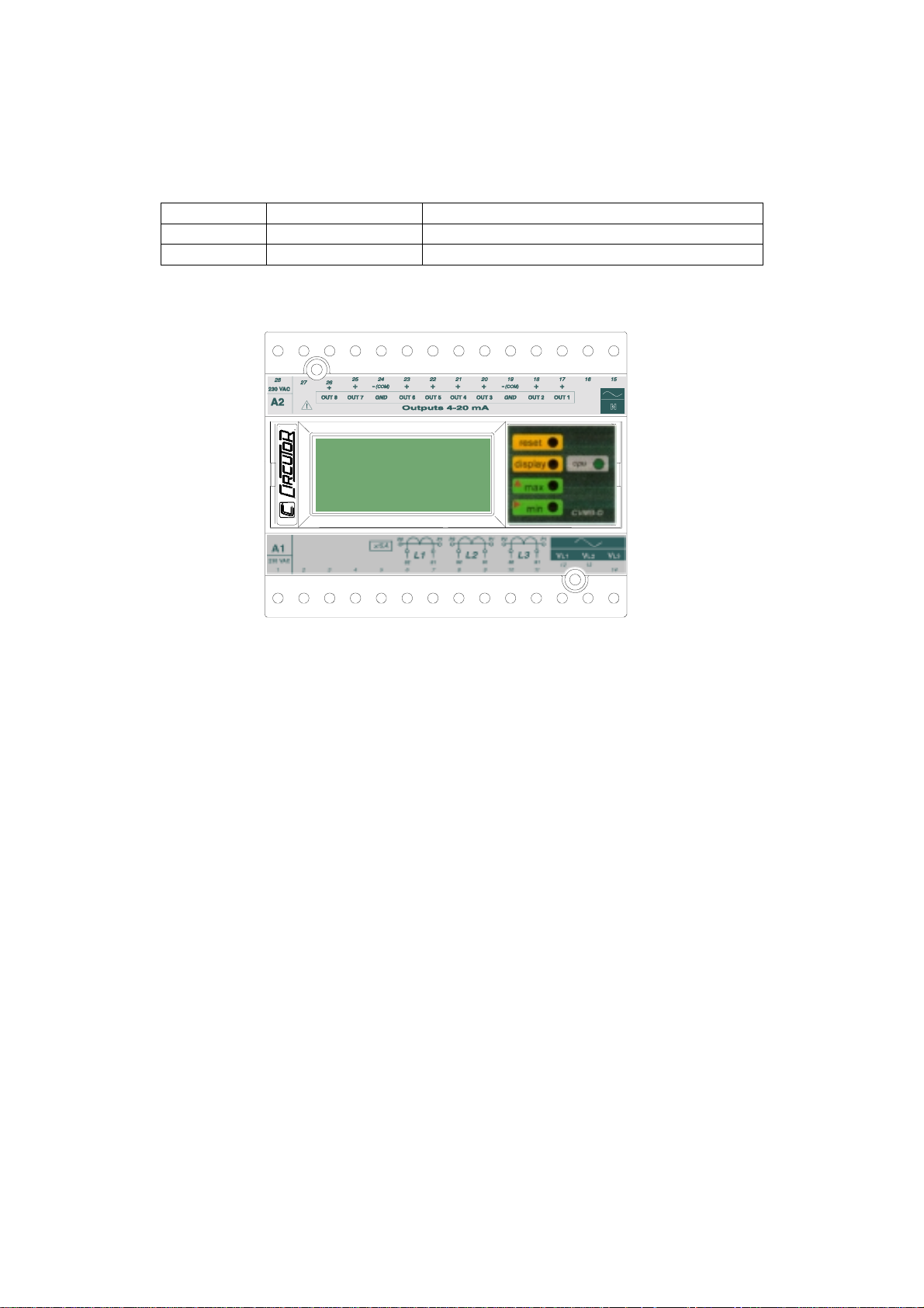
1.3.- CVM-BD-420 types
Two CVM-BD-420 types are available according to the number of analog outputs
that the analyzer equips:
Code Type Features
7 70 262 CVM-BD-420-4 4C + 4 analog outputs + display
7 70 263 CVM-BD-420-8 4C + 8 analog outputs + display
2.- MAIN CHARACTERISTICS
The CVM-BD-420-4 & CVM-BD-420-8 power meters are programmable measuring
instruments, offering several operation possibilities selectable in their SETUP option.
Before power supplying the instrument, read the CONNECTIONS and SETUP
sections and choose the most suitable operation mode for getting your desired data.
4 or 8 user-programmable analog outputs are available. (Section 5.10)
The CVM-BD-420-.. is an instrument which measures, calculates and displays all the
main electrical parameters at any electrical network (balanced or not). The
measuring is true RMS value, through three a.c. Voltage inputs and three a.c.
Current inputs (from Current Transformers .../ 5A).
Page 5

-- Supply network analyzers CVM-BD-420-4 & CVM-BD-420-8 -- M98132301-20 --- Page Nº 4
By means of an internal microprocessor it simultaneously measures:
Parameter L1 L2 L3 Average Addition
Voltage (phase-neutral) x x x x
Voltage (phase-phase) x x x x
Current x x x x
Active power x x x X
Reactive power L x x x X
Reactive power C x x x X
Power factor x x x x
Apparent power X
Frequency x
Parameter CVM-BD-420-..
Date/Time dd/mm/yy hh:mm:ss TIME
Active energy ( two indep. meters: demanded energy (+)
and generated energy (--) )
Reactive energy (inductive), two indep. meters kvarh.L (+) and (--)
Reactive energy (capacitive), two indep. meters kvarh.C (+) and (--)
---------------------------------------------------
The CVM-BD-420-.. allows reading up to 54 electrical parameters in 18 screens,
shown in a three line numerical display, where you can see:
(a) Phase-phase or phase-neutral voltage of the three phases
(b) 51 user-selectable parameters according to the model (see
attached table)
kWh (+) and (--)
And also the MAXIMUM POWER DEMAND: The power demand is integrated
during a prefixed period.
Page 6
-- Supply network analyzers CVM-BD-420-4 & CVM-BD-420-8 -- M98132301-20 --- Page Nº 5
You can select:
a) The parameter to be controlled (it can measure active power kW,
apparent power kVA or three phase average current AIII).
b) The demand period (1 to 60 min.).
This power demand function works with sliding window : shows the accumulated
demand over the last period from "now".
---------------------------------------------------------------------------------------------
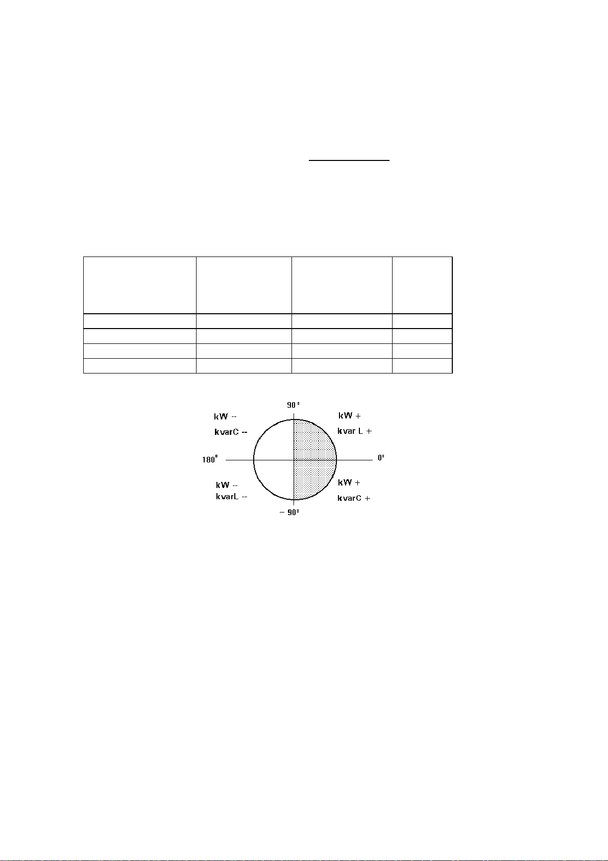
The CVM-BD-420-.. is a 4 quadrant analyzer, that is, this can automatically
detect the energy sign:
Example of the
phase difference
between voltage
and current
30º kW + kvar L + +
300º kW + kvar C + --
210º kW -- kvar L -- +
120º kW -- kvar C -- --
Active power
kW or kW.h
Reactive power
kvar or kvar.h
P.F.
Page 7

-- Supply network analyzers CVM-BD-420-4 & CVM-BD-420-8 -- M98132301-20 --- Page Nº 6
2.1- Other Characteristics
- DIN rail mounting device with low dimensions.
- True RMS value measurements.
- 4 or 8 user-programmable analog inputs.
- Measurements in all four quadrants (equivalent to CVMk-4C ).
- Power demand control.
- Memorizes Maximum and Minimum values.
- Two leds for indication of CPU and communication operation
- Incorporates the calculation of the harmonic distortion.
3.- INSTALLATION AND STARTUP
The manual you hold in your hands contains information and warnings that the
user should respect in order to guarantee a proper operation of all the instrument
functions and keep its safety conditions.
The instrument must not be powered and used until its definitive assembly on the
cabinet’s door.
Whether the instrument is not used as manufacturer’s specifications, the
protection of the instrument can be damaged.
When any protection failure is suspected to exist (for example, it presents external
visible damages), the instrument must be immediately powered off. In this case
contact a qualified service representative.
Page 8

-- Supply network analyzers CVM-BD-420-4 & CVM-BD-420-8 -- M98132301-20 --- Page Nº 7
3.1.- INSTALLATION
Before applying AC power to the, check following points :
a.- Supply voltage :
- Power supply V a.c. ( Single phase ) 50 ...60 Hz
230 V a.c.
- Frequency : 50 ... 60 Hz
- Supply tolerance : + 10 % / --15 %
- Connection terminals : Terminals 1 - 28
- Instrument burden : 6 VA
b.- Maximum voltage at the voltage measuring circuit:
Standard : 500 V a.c. phase-neutral / 866 V a.c. between phases
A special model CVM-BD-420-4 & CVM-BD-420-8 for 110 V measur ement is
also available:
100 V a.c. phase-neutral / 173 V a.c. between phases
c.- Maximum admissible current : Transformer of In / 5 A a.c.
d.- Operation conditions :
- Operating temperature : 0 to 50ºC
- Humidity : 25 to 80 % R.H. non-condensing
e.- Safety : Designed to meet protection class II as per EN 61010.
Page 9

-- Supply network analyzers CVM-BD-420-4 & CVM-BD-420-8 -- M98132301-20 --- Page Nº 8
Mounting:
Instrument is to be mounted on DIN rail mounting device with low dimensions.
All connections keep inside the cabinet.
Note that with the instrument powered on, the terminals could be dangerous to
touching and cover opening actions or elements removal may allow accessing
dangerous parts. Therefore, the instrument must not be used until this is completely
installed.
The instrument must be connected to a power supply circuit protected with gl type
(IEC 269 ) or M type fuses rated between 0.5 and 2 A. This circuit should be
provided with an automatic switch or any equivalent element to disconnect the
instrument from the power supply network. The supply and measuring voltage
circuits will be both connected through a wire with a minimum cross-section of 1
mm2. The line of the current transformer secondary will have a minimum crosssection of 2,5 mm2.
Page 10
-- Supply network analyzers CVM-BD-420-4 & CVM-BD-420-8 -- M98132301-20 --- Page Nº 9
3.2.- CVM-BD-420-.. Connection terminal
Terminal No Designation Concept
1 - 28 A1 - A2 supply voltage : 230 V a.c.
17 Out 1 4-20 mA type output 1
18 Out 2 4-20 mA type output 2
19 GND Ground
20 Out 3 4-20 mA type output 3
21 Out 4 4-20 mA type output 4
22 Out 5 4-20 mA type output 5
23 Out 6 4-20 mA type output 6
24 GND Ground
25 Out 7 4-20 mA type output 7
26 Out 8 4-20 mA type output 8
15 N NEUTRAL
14 VL3 Voltage phase 3
13 VL2 Voltage phase 2
12 VL1 Voltage phase 1
11 - 10 I L3: s1 - s2 Current phase L3 .../ 5 A
9 - 8 I L2: s1 - s2 Current phase L2 .../ 5 A
7 - 6 I L1: s1 - s2 Current phase L1 .../ 5 A
NOTE: Current inputs are isolated
Page 11

-- Supply network analyzers CVM-BD-420-4 & CVM-BD-420-8 -- M98132301-20 --- Page Nº 10
3.3.- Connection drawing for the CVM-BD-420-..
a.- Connection diagram of the CVM-BD-420-4 & CVM-BD-420-8 for a low voltage,
three phase network.
IMPORTANT REMARK! If power = 0 is shown for any of the phases (codes 03, 09
and 15) and voltage and current are not zero for this phase, check out following
points:
- Assure that L1, L2 and L3 phases coincide in voltage and current.
- Correct polarity? Reverse the current transformer placed at this phase.
Page 12

-- Supply network analyzers CVM-BD-420-4 & CVM-BD-420-8 -- M98132301-20 --- Page Nº 11
b.- CVM-BD-420-4 & CVM-BD-420-8: 3 current transformers + two voltage
transformer :
Page 13

-- Supply network analyzers CVM-BD-420-4 & CVM-BD-420-8 -- M98132301-20 --- Page Nº 12
c.- CVM-BD-420-4 & CVM-BD-420-8 : Two current transformers + 2 voltage
transformers.
S2 of the current transformer grounded to earth
Page 14

-- Supply network analyzers CVM-BD-420-4 & CVM-BD-420-8 -- M98132301-20 --- Page Nº 13
S1 of the current transformer grounded to earth
Page 15

-- Supply network analyzers CVM-BD-420-4 & CVM-BD-420-8 -- M98132301-20 --- Page Nº 14
4.- OPERATION MODE
The instrument has a display with three lines (10 characters every line).
When you switch on the power supply of the CVM-BD-420-.. you will see on the
display "Circ CVM-BD-..." (program version) and following you will read "CARD TYPE
xxxx" (identification of the output options). After some seconds the instrument is
ready to work, showing one of the possible screens.
The display indicates the parameter presently shown.
display
The first display shows the voltage of phase L1 (V1), the voltage of phase L2 (V2)
and the voltage of phase L3 (V3).
220 V12
220 V23
220 V31
If you press the "display" key, we are now reading the CURRENT values for each
phase (A1, A2, A3). However, this screen can be configured in order to display other
different parameters.
When pressing again the "display" key, we will see on display the three previously
programmed parameters (see point 5.5. in the SET-UP section).
If you press the "display" key again you repeat the above mentioned process
( you can see 1 to 18 displays depending of the previous set-up ).
Page 16

-- Supply network analyzers CVM-BD-420-4 & CVM-BD-420-8 -- M98132301-20 --- Page Nº 15
max
Pressing the "max" key, the maximum values for the parameters being shown
appear in the displays.
xxxx MAX
xxxx MAX
xxxx MAX
This function is only valid while you keep pressing the "max" key. If you stop
pressing the key the instantaneous values appear again.
min
Pressing the "min" key, the minimum values for the parameters being shown
appear in the displays.
xxxx MIN
xxxx MIN
xxxx MIN
This function is only valid while you keep pressing the "min" key. If you stop
pressing the key the instantaneous values appear again.
Reset
Pressing the "reset" key the system is reset. This is equivalent to switch off the
power supply of the instrument. The stored maximum and minimum values will be
automatically deleted from the internal memory.
If you are in the setup process and press the "reset" key, you exit it without saving
any modification that you have done and making a reset of the system.
Page 17

-- Supply network analyzers CVM-BD-420-4 & CVM-BD-420-8 -- M98132301-20 --- Page Nº 16
5.- SETUP
To access into the setup menu just follow these steps:
(a) Connect (supply) the instrument.
(b) Press the two green buttons (max, min) simultaneously.
You will see during a few seconds the word "set". It means that we are in the setup
process. Then we go along the different options, step by step:
5.1.- Phase-to-Phase or Phase-to-Neutral voltages
After the word "set" you will see on the three displays the voltages of the phases
L1, L2, L3.
U1 U12
U2 or U23
U3 U31
Phase to Neutral Voltages: U1 , U2 , U3
Phase to Phase Voltages : U12 , U23 , U31
a.- To select one of the voltage options just press the green key "max" and both
options will appear alternately.
b.- When you get in the display the wished option just press the "display" key to
validate it and access to the next setup option.
Page 18

-- Supply network analyzers CVM-BD-420-4 & CVM-BD-420-8 -- M98132301-20 --- Page Nº 17
5.2.- Voltage Transformer Primary
On the screen we read the word "SET U P" followed by 6 digits. They allow us
setting the primary of the voltage transformer.
SET U
P - - -
- - -
Last digit of the first display indicates "U" (Voltage) and first digit of the second
display indicates "P" (Primary). It means that we can set the primary of the voltage
transformer. To avoid mistakes the Voltage red LEDs remain lit on.
a.- To write or modify the value just repeatedly press the "max" key and the blinking
digit value will be increased.
b.- When the value on screen is the proper one, we can pass to the next digit by
pressing the "min" key in order to modify the other values.
c.- When the blinking digit is the last one, pressing the "min" key we go back to the
initial value: set values can be again modified.
d.- Press "display" to pass to the next setup option.
Page 19

-- Supply network analyzers CVM-BD-420-4 & CVM-BD-420-8 -- M98132301-20 --- Page Nº 18
5.3.- Voltage Transformer Secondary
We can now set the value of the secondary of the voltage transformer. Only three
digits are available:
SET U
S
- - -
Same process as in point 5.2:
- "max" key: Allows us modifying the value of the blinking digit. Each time it is
pressed the value is increased.
- "min" key: Allows us the validation of the blinking digit and going to the next one.
- Press "display" to pass to the next setup option.
If the CVM-BD-420-.. is directly connected to the mains (without voltage
transformer) the values of primary and secondary must be the same, for instance
000001/001.
5.4.- Current Transformer Primary
"SET A P" and five digits appear on screen allowing us to set the primary of the
current transformer. The current green LEDs light on to avoid mistakes.
SET A
P - -
- - -
Page 20

-- Supply network analyzers CVM-BD-420-4 & CVM-BD-420-8 -- M98132301-20 --- Page Nº 19
The procedure is the same one done at the previous sections with the "max", "min"
and "display" keys.
NOTES:
- The maximum programmable value is 10.000
- The secondary of the current transformers is not programmable. It is automatically
taken as 5 A (... / 5 A ac)
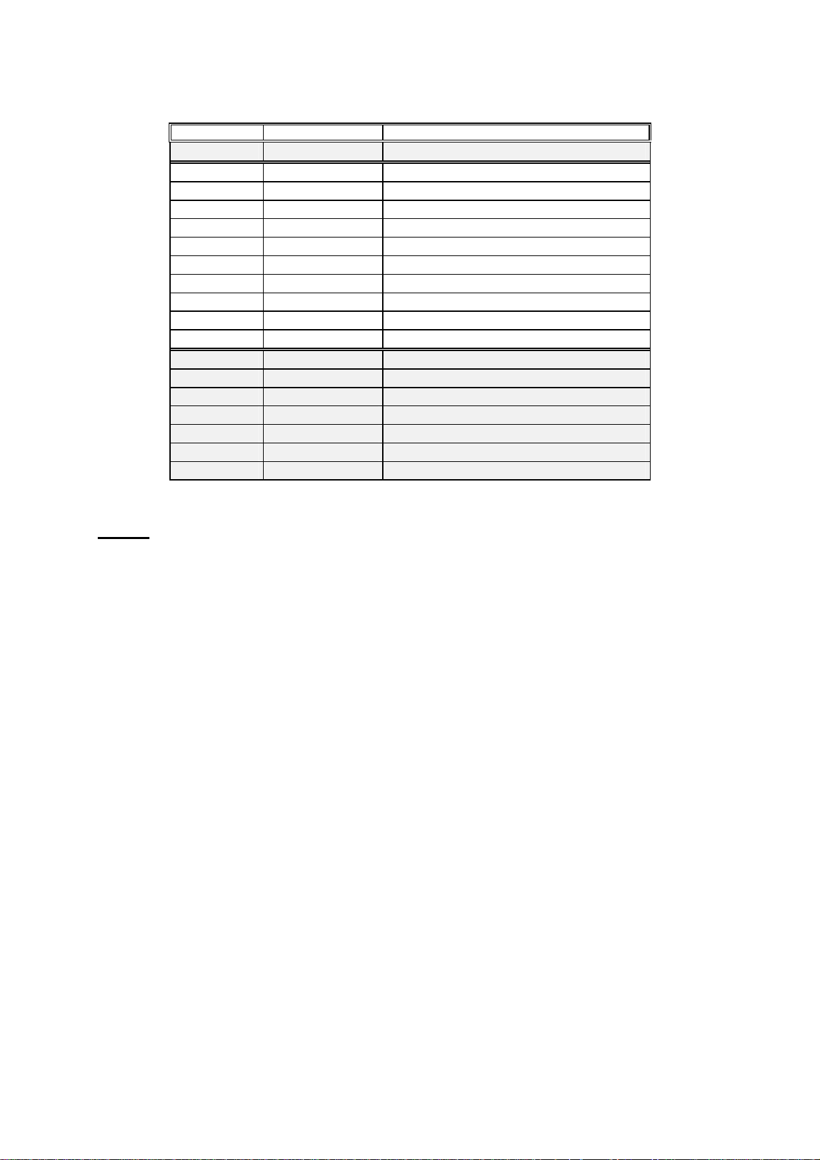
5.5.- Parameter SETUP
This option allows to program until 51 optional parameters that you can see on the
display through 17 possible pages (3 parameters per each page). The CVM-BD-420.. firstly inquires whether you want the default parameter selection.
"max" key : you can select YES or NO. The “display” key allows the validation
of the selected option.
dEF
PAGE
YES
5.5.1.- Select “YES” to program the default parameters. In this case , it pass to the
next option (5.6.- First Page SET-UP )
5.5.2.- If you select “NO” , it allows programming the parameters that you want to
see on the display. Every new page, it asks if you want to continue this set-up .
SET
PAGE
NUMBER
YES xx <--- page Nº
Page 21

-- Supply network analyzers CVM-BD-420-4 & CVM-BD-420-8 -- M98132301-20 --- Page Nº 20
- If you select “SET PAGE YES” , you can program the desired parameters in this
page :
xx A1
xx A2
xx A3
Parameter code ( set-up ) / Parameter symbol
SET-UP
:
- "max" key : Allows us modifying the value of the blinking digit. Each time it is
pressed the value is increased.
- "min" key : Allows us the validation of the blinking digit and going to the next one.
Each display has two digits to select the desired parameters among the ones in the
attached code chart:
Parameter Symbol
phase L1
Single voltage V 1
Current A 1
Active power kW 1
Inductive power kvarL 1
Capacitiva power kvarC 1
Power factor PF 1
Three phase single voltage Vav III
Three phase current Aav III
Three phase active power kW III
Three. ph. inductive power. kvarL III
Three ph. capacitive power kvarC III
Three ph. power factor. PF III
Code Symbol
phase L2
01
02
03
04
05
06
19
20
21
22
23
24
V 2
A 2
kW 2
kvarL 2
kvarC 2
PF 2
Frequency Hz
Three ph. apparent power kVA III
Ph-Ph voltage L1- L2 V 12
Ph-Ph voltage L2 - L3 V 23
Ph-Ph voltage L3 - L1 V 31
Three ph. Ph-Ph voltage Vc III
Code Symbol
phase L3
07
08
09
10
11
12
V 3
A 3
kW 3
kvarL 3
kvarC 3
PF 3
Code
13
14
15
16
17
18
25
26
27
28
29
30
Page 22

-- Supply network analyzers CVM-BD-420-4 & CVM-BD-420-8 -- M98132301-20 --- Page Nº 21
Date/ TIME
dd/mm/yy hh:mm:ss
Active energy kW.h
Reactive energy (inductive) kvarh.L
Reactive energy (capacitive) kvarh.C
Demand power ( kW, kVA, AIII) Pd
Active energy generated kW.h - Reactive energy (inductive) gen. kvarh.L - Reactive energy (capacitive) gen. kvarh.C --
TIME
31
32
33
34
35
36
37
38
Parameter Symbol
phase L1
Voltage harmonic
distortion
Current harmonic
distortion
THD V1
THD A1
Code Symbol
phase L2
54
57
THD V2
THD A2
Code Symbol
phase L3
55
58
THD V3
THD A3
56
59
- For passing to the next page , press "display". In this case the CVM-BD-420-..
inquires again:
SET
PAGE
NUMBER
YES xx
- If you select “SET PAGE YES” , you can set-up a next page.
- If you don’t want to set-up more pages, select “SET PAGE No”, and it pass to the
next set-up option (5.6.- First Page SET-UP ). You can see the first page of voltages
and all the programmed pages .
Code
Page 23

-- Supply network analyzers CVM-BD-420-4 & CVM-BD-420-8 -- M98132301-20 --- Page Nº 22
5.6.- First Page SET-UP
This option allows selecting among fixed or rotary page:
a.- Fixed page : the page is changed pressing the "display" key. The page among
the available ones that we want to see when the CVM-BD-420-.. is powered (or a
reset is made) can be selected.
b.- Rotary pages : the page changes to the next one automatically every 5 seconds.
( “SET AUTO PAGE : Rotate page select “ option ).
Set-up :
- The "max" key allows modifying the selected page. The display shows the different
possible pages.
SET xx
AUTO xx
PAGE xx <-- set-up parameters
- The "display" key allows the validation of the chosen option.
Page 24

-- Supply network analyzers CVM-BD-420-4 & CVM-BD-420-8 -- M98132301-20 --- Page Nº 23
5.7.- Maximum power demand
Push the key "display" and the following screens will appear by display:
1.- DEMAND PERIOD ( 1 to 60 min.) ("SET Per xx")
2.- PARAMETER TO CONTROL ("SET Pd xx")
Three phase active power kW III
Three phase apparent power kVA III
Three phase average current AavIII
21
26
20
Value of power integrated during the programmed demand period.
3.- CLEAR MAXIMUM VALUE IN MEMORY
("CLr Pd xx") no or YES
PROGRAMMING MODE:
- "max" key: allows choosing the different available options.
- "min" key: allows the validation of the blinking digit and go forward to the
next digit (only for the "SET Per xx" option).
- To pass to the next option press "display".
If you don't want to modify anything, just press the "display" key three times without
modifying any value.
- Display: If you program the MAXIMUM POWER DEMAND option, parameter
35, the following appears by display (depending on the pressed key):
display
Present value of the demand power meter (Sliding Window,
according to the set demand period) updated every second.
max
min
MAXIMUM integrated value (since last reset)
HOUR : MINUTE DAY : MONTH (“”HH.MM DD/MM”)
when this maximum has occurred
Page 25

-- Supply network analyzers CVM-BD-420-4 & CVM-BD-420-8 -- M98132301-20 --- Page Nº 24
5.8.- DATE / TIME SETUP
Pressing the "display" key we will see in the CVM-BD-420-.. screen the following:
1.- DAY : MONTH ("SET day dd:mm")
2.- YEAR ("SET YEAR xxxx " ) 4 digits
3.- HOURS : MINUTES ("SET HOUR hh:mm")
For their setup:
- "max" key: Allows modifying the value of the blinking digit.
- "min" key: Allows the validation of the blinking digits and go to the next one.
- To pass to the next option press "display".
If you don't want to modify the time, just press three times "display" without making
any modification.
- Display: If you select the parameter 31, following appears by display:
display
max
min
HOUR .MINUTES
DAY. MONTH
MINUTES . SEC.
Page 26

-- Supply network analyzers CVM-BD-420-4 & CVM-BD-420-8 -- M98132301-20 --- Page Nº 25
5.9.- Clearing energy counters
On display we see "CLR ENER no" (Clear energy counters).
- "max" : To select "YES" or "no"
- "display" : To validate the selected option. Once finishing this option, all the
modifications that we have done are saved in memory and the setup process is
finished.
- Display : If any of the energies is programmed (kWh, kvarhL or kvarhC), it is
displayed as follows:
[display]
[max]
[min]
XXXX kW.h 4 counter digits (more significant ) / units
XXX XXX. XXX complete counter
XXXX (1 )
4 digits / Tariff type ( 1, 2 or 3 )
Example : If the accumulated energy is 32.534,810 kWh, it will be displayed
as follows:
[display]
[max]
[min]
2534 kW.h
32534. 810
2534 ( 1 )
Page 27

-- Supply network analyzers CVM-BD-420-4 & CVM-BD-420-8 -- M98132301-20 --- Page Nº 26
5.10.- 4 - 20 mA outputs: CVM-BD-420-4 (4 analog outputs) and
CVM-BD-420-8 (8 analog outputs)
With these outputs we can configure the CVM-BD420 to give an output of 4 - 20
mA d.c. or of 0 - 20 mA d.c. ( resolution of 4.000 points ) proportional to any of
the parameters measured by the CVM-BD, with the ability of setting the scale
(offset and full scale).
On the CVM-BD-420-.. screen following messages appear at this SET-UP point
(provided the right module is connected to the equipment):
a.- Parameter choice:
dA 1 OUTPUT D/A No.1
Code
xx
- "max" -- "min" keys: allow the selection of any parameter from 1 to 30, the 35, or
from 54 to 59.
- “display” key: validates the selected option and passes to the next setup screen.
b.- Selection of 0 - 20 mA or 4 - 20 mA :
dA 1 OUTPUT D/A Nr.1
Scal Scale :
4 - 20
- "display": to validate the selected option and pass to the next setup screen.
allows choosing a 0 - 20 mA
or 4 - 20 output ("max" or "min" key)
Parameter No.
Page 28

-- Supply network analyzers CVM-BD-420-4 & CVM-BD-420-8 -- M98132301-20 --- Page Nº 27
c.- Scale offset:
Value of the parameter that we assign as the zero of the scale.
dA 1 OUTPUT D/A No.1
Zero Zero of the scale:
x.xxx
(four digits with floating decimal point)
allows choosing the zero of the scale
- "max" key: it allows modifying the value of the blinking value.
Every time it is pressed the number is increased.
- "min" key: it allows validating the blinking value and go to the next digit.
NOTE : When you arrive at the last digit, you can move the position of the decimal
point with the "max" key.
- "display": to validate the selected option and pass to the next setup screen.
d.- Full scale: Value of the parameter to which we assign the 20 mA.
dA 1 OUTPUT D/A No.1
F.ESC Full scale:
x.xxx
allows choosing the full scale (20 mA)
(four digits with floating decimal point)
Proceed as in the previous section.
- To access the next option, press "display": setup options for the rest of analog
outputs will appear up. Setup procedure is similar for any output.
Page 29

-- Supply network analyzers CVM-BD-420-4 & CVM-BD-420-8 -- M98132301-20 --- Page Nº 28
1.- Output calculation:
Resolution = 20 − Zero .
F. scale - offset
MA = (( F. scale - offset ) x Resolution) + Zero
MV = mA x ohms
- Maximum load is:
CVM-BD-420-4: ................400 Ω
CVM-BD-420-8: ................300 Ω
- The maximum allowable offset is a value equal to the 90% of the full scale.
-
Output of the power factor parameter ( P.F.):
0/4 mA ---------------------------- -------------------------20 mA
+0.00 Ind. 1.00 Cap. – 0.00
2.- Default full scale:
Offset & f. scale = defined by the
user
Zero = 0 mA or 4 mA
mV
(100 ohms)
= mA x 100
Parameter Condition Full scale ( 20 mA )
Voltages Primary < 500 Primary x 500 /secondary
(V) Primary > 500 Voltage primary
Currents (A) Current primary
Powers For one phase voltage primary x current primary / 1000
(kW) Three phase value voltage primary x current primary x 3 / 1000
Frequency (Hz) 65
P.F. – 0.00
Page 30

-- Supply network analyzers CVM-BD-420-4 & CVM-BD-420-8 -- M98132301-20 --- Page Nº 29
6.- TECHNICAL FEATURES
Power supply : see specifications on the CVM-BD-420-.. rear
- CVM-BD-420-..: Single phase 230 V a.c.
Voltage tolerance: +10 % / -15 %
Frequency: 50 ... 60 Hz
Power consumption ..................... 6 VA
Operation temperature ................ 0 to 50º C
Measuring Circuits :
Rated voltage .... 500 V a.c. Phase - Neutral / 866 V a.c. between phases
Other voltages ............With appropriate voltage transformers
Rated current ..............In / 5 A (isolated input like ITF types)
Permanent overload .....1.2 In
Current input power .....0.6 VA
Maximum burden per 20 mA channel :
CVM-BD-420-4: ................400 Ω
CVM-BD-420-8: ................300 Ω
Accuracy class:
Voltage ...................................... 0.5 % of readout ± 2 digits
Current ...................................... 0.5 % of readout ± 2 digits
Power ......................................... 1 % of readout ± 2 digits
Test conditions :
- Errors due to Voltage T. and Current T. are not included
- Temperature between + 5 ºC and + 45 ºC
- Power factor between 0.5 and 1
- Measured values between 5 % ... 100 %
Constructive characteristics :
Box type : Self-extinguishing, plastic casing
Connection : Metallic terminals with "posidraft" screws
Fixing : Fitted onto symmetrical DIN 46277 (EN 50022) rail
Screw fixing (Passing hole ∅ 4,2 mm).
Frontal cover : Lexan
Protection : Built-in relay : IP 41
Terminals : IP 20
Dimensions 140 x 70 x 110 mm ( 8 modules relay as per DIN 43 880)
Safety Category II , as perEN-61010
Standards EN 60664, EN 61010-1, EN 61036, IEC 60801 , IEC 60571-1,
EN 50081-1, EN 50082-1, VDE 110 , UL 94
Page 31

-- Supply network analyzers CVM-BD-420-4 & CVM-BD-420-8 -- M98132301-20 --- Page Nº 30
Dimensions :
45
140
110
70
7.- SAFETY CONSIDERATIONS
All installation specification described at the previous chapters named
INSTALLATION AND STARTUP, INSTALLATION MODES and SPECIFICATIONS.
Note that with the instrument powered on, the terminals could be dangerous to
touching and cover opening actions or elements removal may allow accessing
dangerous parts. This instrument is factory-shipped at proper operation condition.
Page 32

-- Supply network analyzers CVM-BD-420-4 & CVM-BD-420-8 -- M98132301-20 --- Page Nº 31
8.- MAINTENANCE
The CVM-BD-420-.. does not require any special maintenance. No adjustment,
maintenance or repairing action should be done over the instrument open and
powered and, should those actions are essential, high-qualified operators must
perform them.
Before any adjustment, replacement, maintenance or repairing operation is carried
out, the instrument must be disconnected from any power supply source.
When any protection failure is suspected to exist, the instrument must be
immediately put out of service. The instrument’s design allow a quick replacement in
case of any failure.
9.- TECHNICAL SERVICE
For any inquiry about the instrument performance or whether any failure happens,
contact to CIRCUTOR’s technical service.
CIRCUTOR S.A. - Aftersales Service
Vial Sant Jordi, s/n
08232 - Viladecavalls
tel - +34 - 93-745 29 00
fax - +34 - 93-745 29 14
e-mail: central@circutor.es
 Loading...