

Page 1
Power analyzer
CVM-B100 CVM-B150
INSTRUCTION MANUAL
(M010B01-03-15B)
Page 2

CVM-B100 - CVM-B150
2
Instruction Manual
Page 3
CVM-B100 - CVM-B150
SAFETY PRECAUTIONS
Follow the warnings described in this manual with the symbols shown below.
DANGER
Warns of a risk, which could result in personal injury or material damage.
ATTENTION
Indicates that special attention should be paid to a speci c point.
If you must handle the unit for its installation, start-up or maintenance, the following
should be taken into consideration:
Incorrect handling or installation of the unit may result in injury to personnel as well as damage
to the unit. In particular, handling with voltages applied may result in electric shock, which may
cause death or serious injury to personnel. Defective installation or maintenance may also
lead to the risk of re.
Read the manual carefully prior to connecting the unit. Follow all installation and maintenance
instructions throughout the unit’s working life. Pay special attention to the installation standards of the National Electrical Code.
Refer to the instruction manual before using the unit
In this manual, if the instructions marked with this symbol are not respected or carried out correctly, it can
result in injury or damage to the unit and /or installations.
CIRCUTOR, SA reserves the right to modify features or the product manual without prior noti cation.
DISCLAIMER
CIRCUTOR, SA reserves the right to make modi cations to the device or the unit speci ca-
tions set out in this instruction manual without prior notice.
CIRCUTOR, SA on its web site, supplies its customers with the latest versions of the device
speci cations and the most updated manuals.
www.circutor.com
Instruction Manual
3
Page 4
CVM-B100 - CVM-B150
CONTENTS
SAFETY PRECAUTIONS .......................................................................................................................................3
DISCLAIMER ..........................................................................................................................................................3
CONTENTS ............................................................................................................................................................. 4
REVISION LOG .......................................................................................................................................................7
1.- VERIFICATION UPON RECEPTION ................................................................................................................. 8
2.- PRODUCT DESCRIPTION ................................................................................................................................ 8
3.- UNIT INSTALLATION ...................................................................................................................................... 10
3.1.- PRIOR RECOMMENDATIONS.................................................................................................................10
3.2.- INSTALLATION ........................................................................................................................................ 11
3.3.- UNIT TERMINALS .................................................................................................................................... 12
3.3.1.- Terminals on the upper face ........................................................................................................12
3.3.2.- Terminals on the lower face .......................................................................................................... 13
3.4.- CONNECTION DIAGRAMS ....................................................................................................................14
3.4.1.- Three-phase network measurement with a 4-wire connection. .................................................14
3.4.2.- Three-phase network measurement with a 3-wire connection. ................................................16
3.4.3.- Three-phase network measurement with a 3-wire connection and transformers with an
ARON connection. ...................................................................................................................................18
3.4.4.- Two-phase network measurement with a 3-wire connection. ....................................................19
3.4.5.- Single-phase network measurement, phase to phase, with a 2-wire connection. .................. 20
3.4.6.- Single-phase network measurement, phase to neutral, with a 2-wire connection. ................. 21
3.5.- STARTING UP THE UNIT ........................................................................................................................ 22
4.- OPERATION ...................................................................................................................................................26
4.1.- OPERATING PRINCIPLE ......................................................................................................................... 26
4.2.- MEASUREMENT PARAMETERS ............................................................................................................ 27
4.3.- KEYPAD FUNCTIONS..............................................................................................................................28
4.4.- DISPLAY ...................................................................................................................................................29
4.4.1.- UPPER AREA .................................................................................................................................. 29
4.4.2.- LOWER AREA ................................................................................................................................. 31
4.4.3.- CENTRAL AREA ............................................................................................................................. 31
4.5.- LED INDICATORS .................................................................................................................................... 34
4.6.- INPUTS ..................................................................................................................................................... 35
4.7.- OUTPUTS ................................................................................................................................................. 35
5.- DISPLAY AND CONFIGURATION ..................................................................................................................36
5.1.-MEASUREMENT DISPLAY MENU
..................................................................................................... 37
5.1.1.- Display 1 parameter. ............................................................................................................... 38
5.1.2.- Display 3 parameters..............................................................................................................63
5.1.3.- Display 4 parameters..............................................................................................................79
5.1.4.- Phasors....................................................................................................................................96
5.1.5.- Standard phasors. .................................................................................................................97
5.1.6.- Harmonics. ..............................................................................................................................98
5.1.7.- Integrated functions. ............................................................................................................ 100
5.1.8.- Expansion modules. ............................................................................................................ 101
5.2.- ALARM MENU
5.3.- ENERGY CLOSES MENU
5.3.1.-
tariff. .........................................................................................................................................................106
5.4.- LOG MENU
5.4.1.-
5.4.2.-
5.5.- INFORMATION MENU
Active energy closes III of the total tariff and of reactive energy III of the total
Alarm log .............................................................................................................................108
Event log ................................................................................................................................109
..................................................................................................................................103
.............................................................................................................. 105
....................................................................................................................................107
..................................................................................................................... 110
4
Instruction Manual
Page 5
CVM-B100 - CVM-B150
5.5.1.- System information. ............................................................................................................ 111
5.5.2.-
5.5.3.-
5.5.4.- CIRCUTOR S.A. ....................................................................................................................123
5.6.- SETUP MENU
5.6.1.- Date and time. ......................................................................................................................126
5.6.2.- Time zone.............................................................................................................................127
5.6.3.- Language. ............................................................................................................................. 128
5.6.4.-
5.6.5.- Measurement connection mode. ........................................................................................ 130
5.6.6.- Ratio of voltage transformers. ............................................................................................ 131
5.6.7.- Ratio of current transformers. ............................................................................................ 133
5.6.8.- Display of variables. ............................................................................................................135
5.6.9.-
5.6.10.- Installation data. .................................................................................................................137
5.6.11.- Energy consumption costs. .............................................................................................. 138
5.6.12.- Energy generation costs. .................................................................................................. 140
Integrated functions. ........................................................................................................... 112
Expansion modules. ............................................................................................................ 113
................................................................................................................................... 124
Access key. ............................................................................................................................129
Demand. ................................................................................................................................. 136
5.6.13.- CO2 consumption emissions. ...........................................................................................141
5.6.14.- CO2 generation emissions. ...............................................................................................143
5.6.15.- Relay digital outputs. .........................................................................................................144
5.6.16.- Transistor digital outputs. ................................................................................................. 152
5.6.17.- Digital inputs. .....................................................................................................................161
5.6.18.- Integrated communications. ............................................................................................. 167
5.6.19.- Parameter reset. ................................................................................................................. 172
5.6.20.- User interface ..................................................................................................................... 173
5.6.21.- Expansion modules. .......................................................................................................... 175
6.- INTEGRATED COMMUNICATIONS .............................................................................................................. 176
6.1.- CONNECTIONS ...................................................................................................................................... 176
6.2.- MODBUS PROTOCOL ...........................................................................................................................177
6.2.1.- Example of MODBUS query ........................................................................................................ 178
6.3.- MODBUS MEMORY MAP ......................................................................................................................178
6.3.1.- Measurement Variables ...............................................................................................................178
6.3.2.- Current Energy Variables ............................................................................................................180
6.3.3.- Maximum Demand Variables ......................................................................................................184
6.3.4.- Voltage and current harmonics. .................................................................................................185
6.3.5.- Cost variables ..............................................................................................................................187
6.3.6.- Angle variables ............................................................................................................................. 187
6.3.7.- Unit conguration variables .......................................................................................................188
6.3.8.- Other unit variables .....................................................................................................................201
6.3.9.- Deleting parameters ....................................................................................................................204
6.4.- BACnet PROTOCOL ..............................................................................................................................205
6.5.- PICS MAP ............................................................................................................................................... 206
7.- EXPANSION MODULES ...............................................................................................................................209
7.1.- INSTALLATION ......................................................................................................................................209
7.2.- RELAY DIGITAL INPUTS/OUTPUTS ..................................................................................................... 213
7.2.2.- CONNECTION DIAGRAMS ..........................................................................................................214
7.2.3.- CONFIGURATION ......................................................................................................................... 215
Instruction Manual
5
Page 6

CVM-B100 - CVM-B150
7.2.4.- MODBUS COMMUNICATIONS ..................................................................................................... 219
7.3.- TRANSISTOR DIGITAL INPUTS/OUTPUTS .........................................................................................227
7.3.1.- CONNECTION TERMINALS ......................................................................................................... 227
7.3.2.- CONNECTION DIAGRAMS .......................................................................................................... 228
7.3.3.- CONFIGURATION ......................................................................................................................... 229
7.3.4.- COMUNICACIONES MODBUS .................................................................................................... 232
7.4.- ANALOGUE INPUTS/OUTPUTS ........................................................................................................... 243
7.4.1.- CONNECTION TERMINALS ......................................................................................................... 243
7.4.2.- CONNECTION DIAGRAMS .......................................................................................................... 245
7.4.3.- CONFIGURATION ......................................................................................................................... 246
7.4.4.- MODBUS COMMUNICATIONS ..................................................................................................... 254
7.5.- MODBUS/TCP BRIDGE COMMUNICATIONS MODULE ...................................................................... 259
7.5.1.- CONNECTION TERMINALS ......................................................................................................... 259
7.5.2.- LEDs ............................................................................................................................................. 259
7.5.3.- CONNECTION DIAGRAM ............................................................................................................. 260
7.5.4.- CONFIGURATION ......................................................................................................................... 260
7.5.5.- MODBUS COMMUNICATIONS ..................................................................................................... 267
7.6.- LONWORKS COMMUNICATIONS MODULE ........................................................................................ 268
7.6.1.- CONNECTION TERMINALS ......................................................................................................... 268
7.6.2.- CONNECTION DIAGRAM ............................................................................................................. 268
7.6.3.- CONFIGURATION ......................................................................................................................... 269
7.6.4.- MODBUS COMMUNICATIONS ..................................................................................................... 271
7.6.5.- LIST OF LONWORKS LOGS ........................................................................................................ 272
7.7.- PROFIBUS COMMUNICATIONS MODULE........................................................................................... 280
7.7.1.- CONNECTION TERMINALS ......................................................................................................... 280
7.7.2.- LEDs ............................................................................................................................................. 280
7.7.3.- CONNECTION DIAGRAM ............................................................................................................. 281
7.7.4.- CONFIGURATION ......................................................................................................................... 282
7.7.5.- MODBUS COMMUNICATIONS ..................................................................................................... 284
7.7.6.- VARIABLES PROFIBUS GSD FILE ............................................................................................ 284
7.8.- MBUS COMMUNICATIONS MODULE................................................................................................... 290
7.8.1.- CONNECTION TERMINALS ......................................................................................................... 290
7.8.2.- CONNECTION DIAGRAM ............................................................................................................. 290
7.8.3.- CONFIGURATION ......................................................................................................................... 291
7.8.4.- MODBUS COMMUNICATIONS ..................................................................................................... 293
7.8.5.- M-BUS COMMUNICATIONS ......................................................................................................... 294
7.9.- DATA STORAGE MODULE, DATALOGGER......................................................................................... 296
7.9.1.- CONNECTION TERMINALS ......................................................................................................... 296
7.9.2.- LEDs ............................................................................................................................................. 296
7.9.3.- CONNECTION DIAGRAM ............................................................................................................. 297
7.9.4.- CONFIGURATION ......................................................................................................................... 298
7.9.5.- MODBUS COMMUNICATIONS ..................................................................................................... 301
8.- SOFTWARE UPDATE ...................................................................................................................................302
8.1.- UNIT SOFTWARE UPDATE. .................................................................................................................. 303
8.2.- EXPANSION MODULES UPDATE ......................................................................................................... 303
9.- TECHNICAL FEATURES ..............................................................................................................................305
10.- TECHNICAL FEATURES OF EXPANSION MODULES ..............................................................................309
10.1.- TRANSISTOR DIGITAL INPUTS/OUTPUTS .......................................................................................309
10.2.- RELAY DIGITAL INPUTS/OUTPUTS ................................................................................................... 310
10.3.- DIGITAL ANALOGUE INPUTS/OUTPUTS .......................................................................................... 311
10.4.- MODBUS TCP ( Bridge ) COMMUNICATIONS ................................................................................... 312
10.5.- LONWORKS COMMUNICATIONS ...................................................................................................... 313
10.6.- PROFIBUS COMMUNICATIONS ......................................................................................................... 314
10.7.- MBUS COMMUNICATIONS ................................................................................................................. 315
10.8.- DATA STORAGE, DATALOGGER ....................................................................................................... 316
11.- MAINTENANCE AND TECHNICAL SERVICE ............................................................................................ 318
12.- GUARANTEE ............................................................................................................................................... 318
13.- CE CERTIFICATE ........................................................................................................................................ 319
6
Instruction Manual
Page 7

CVM-B100 - CVM-B150
REVISION LOG
Date Revision Description
06/14 M010B01-03-14A Initial Version
05/15 M010B01-03-15A
07/15 M010B01-03-15B
Table 1: Revision log.
Introduction of expansion modules:
M-CVM-AB-Modbus TCP (Bridge),
M-CVM-AB-LON
M-CVM-AB-Probus
M-CVM-AB-MBus
M-CVM-AB-Datalogger
Changes in the following sections:
3.5. - 4.4.1.- 5.1. - 5.3. - 5.4.- 5.5.3.3. - 5.6.- 6.3. - 6.4. - 7.5.4. - 7.5.5. -
7.8. - 9
Changes in the following sections:
7.3.1. - 9.
Note: Unit images are for illustrative purposes only and may differ from the actual unit.
Instruction Manual
7
Page 8
CVM-B100 - CVM-B150
1.- VERIFICATION UPON RECEPTION
Check the following points upon receiving the unit:
a) The unit meets the specications described in your order.
b) The unit has not suffered any damage during transport.
c) Perform an external visual inspection of the unit prior to switching it on.
d) Check that it has been delivered with the following:
- An installation guide,
- 4 Retainers used to attach the unit,
- 5 plug-in connectors with screws,
- 1 seal,
If any problem is noticed upon reception, immediately contact the transport
company and/or CIRCUTOR's after-sales service.
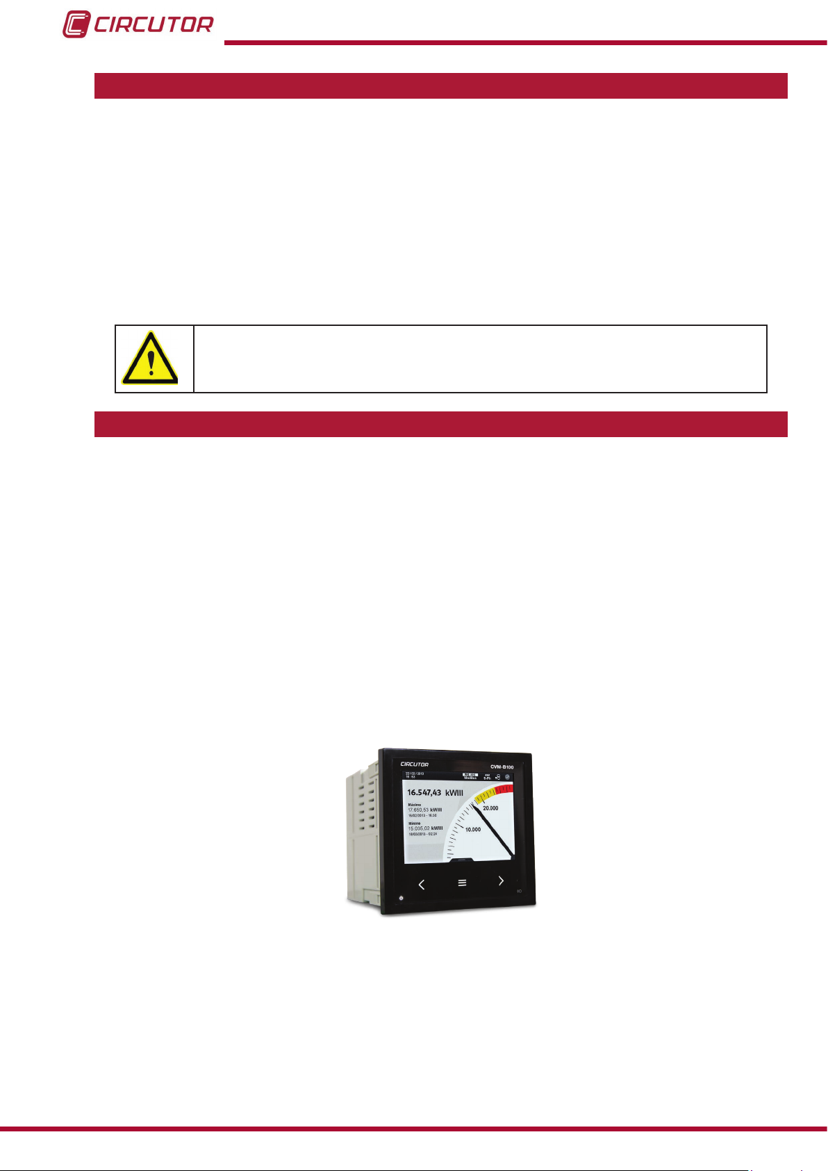
2.- PRODUCT DESCRIPTION
The CVM-B unit measures, calculates and displays the main electrical parameters in single-phase networks, with and without neutral two-phase networks, balanced three-phase networks, with ARON measurement or unbalanced networks. The measurement is taken in RMS,
via four AC voltage inputs and four current inputs.
The current measurement is taken indirectly with transformers /5, /1 or with efcient transformers from the MC1 and MC3 series.
It is a modular unit that can be expanded using expansion modules with different functions.
There are 2 unit models:
CVM-B100, with a 3.5’’ display.
CVM-B150, with a 5.6’’ display.
The unit features:
- 3 keys that allow you to browse between the various screens and program
the unit.
- 3 indicator LEDs: CPU, ALARM and on the navigation keys.
- LCD Display, for displaying all parameters.
8
Instruction Manual
Page 9

CVM-B100 - CVM-B150
- 2 digital inputs, to select the tariff, detect the logic state of external signals or as act
as an impulse input.
- 2 transistor digital outputs, fully programmable.
- 2 relay digital outputs, fully programmable.
- RS-485 communications, with two serial protocols: MODBUS RTU ® and BACnet.
The CVM-B can be expanded with the following expansion modules:
M-CVM-AB-8I-8OTR, expansion module with 8 transistor digital inputs and 8 tran-
sistor digital outputs.
M-CVM-AB-8I-8OR, expansion module with 8 relay digital inputs and 8 relay digital
outputs.
M-CVM-AB-4AI-8AO, expansion module with 4 analogue inputs and 8 analogue out
puts.
M-CVM-AB-Modbus/TCP( Bridge), expansion module for connecting the unit to a
Modbus/TCP network and as an Ethernet to RS-485 gateway.
M-CVM-AB-LON, expansion module for connecting the unit to a LonWorks network.
M-CVM-AB-Probus, expansion module for connecting the unit to a Probus network.
M-CVM-AB-MBus, expansion module for connecting the unit to a M-Bus network.
M-CVM-AB-Datalogger, expansion module that can be used to store data in the em-
bedded PowerStudio platform integrated in the module.
Instruction Manual
9
Page 10

CVM-B100 - CVM-B150
3.- UNIT INSTALLATION
3.1.- PRIOR RECOMMENDATIONS
In order to use the unit safely, it is critical that individuals who handle it follow the
safety measures set out in the standards of the country where it is being used,
use the necessary personal protective equipment, and pay attention to the various warnings indicated in this instruction manual.
The CVM-B unit must be installed by authorised and qualied staff.
The power supply plug must be disconnected and measuring systems switched off before handling, altering the connections or replacing the unit. It is dangerous to handle the unit while it is
powered.
Also, it is critical to keep the cables in perfect condition in order to avoid accidents, personal
injury and damage to installations.
The manufacturer of the unit is not responsible for any damage resulting from failure by the
user or installer to observe the warnings and/or recommendations set out in this manual, nor for
damage resulting from the use of non-original products or accessories or those made by other
manufacturers.
If an anomaly or malfunction is detected in the unit, do not use it to take any measurements.
Inspect the work area before taking any measurements. Do not take measurements in dangerous areas or where there is a risk of explosion.
Disconnect the unit from the power supply (unit and measuring system power
supply) before maintaining, repairing or handling the unit's connections.
Please contact the after-sales service if you suspect that there is an operational
fault in the unit.
10
Instruction Manual
Page 11

CVM-B100 - CVM-B150
3.2.- INSTALLATION
The unit is installed on a panel. All connections are located inside the electric panel.
Table 2: Panel drill holes for installation.
Model Panel drill hole (according to DIN 43700)
CVM-B100 92
CVM-B150 138
+0.8
+0.8
x 92
x 138
+0.8
+0.8
mm
mm
Terminals, opening covers or removing elements can expose parts that are
hazardous to the touch while the unit is powered. Do not use the unit until it is
fully installed.
The unit must be connected to a power circuit that is protected with gL fuses (IEC 269) or M
fuses, with a rating of 1 to 2 A. It must be tted with a circuit breaker or equivalent device for
disconnecting the unit from the power supply mains.
The power and voltage measuring circuit must be connected with cables that have a minimum
cross-section of 1mm2.
The secondary line of the current transformer will have a minimum cross-section of 2.5 mm
2
.
Instruction Manual
11
Page 12

CVM-B100 - CVM-B150
3.3.- UNIT TERMINALS
The CVM-B terminals are distributed between the upper and lower face of the unit.
3.3.1.- Terminals on the upper face
Table 3:List of terminals on the upper face of the CVM-B.
Terminals of the top side of the unit
, Reference voltage input 10: T1, Digital output of transistor 1
1: V
REF
, Reference voltage neutral 11: T2, Digital output of transistor 2
2: N
REF
3: N, Voltage input neutral 12: T
,Voltage input L3
4: V
L3
5: V
Voltage input L2
L2,
Voltage input L1
6: V
L1,
, Digital input 1
7: I
1
, Digital input 2
8: I
2
, for digital inputs
9: I
c
, Common digital output of transistor
C
13: A(+), RS485
14: B(-), RS485
15: S, GND for RS-485
16, 17: R
18, 19: R
, Relay digital output 1
1
, Relay digital output 2
2
3
2
1
9
7
8
10
11
12
13
14
4 5 6
15
16 17
18
19
Figure 1: CVM-Bx terminals, upper face.
12
Instruction Manual
Page 13
CVM-B100 - CVM-B150
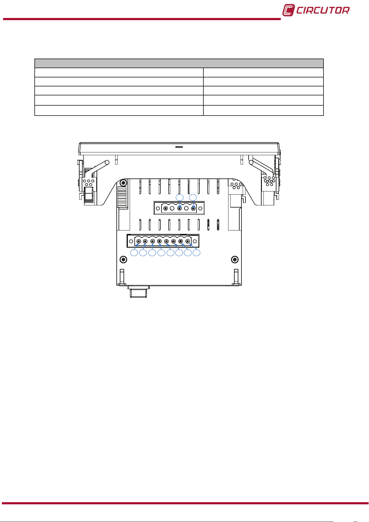
3.3.2.- Terminals on the lower face
Table 4:List of terminals on the lower face of the CVM-B.
Unit terminals
20 : Auxiliary power supply. 25: S2, Current input L2
21: Auxiliary power supply. 26: S1
22: S1
23: S2, Current input L1
24: S1
Current input L1 27: S2, Current input L3
,
28: S1, Neutral current input, LN
Current input L2
,
29: S2, Neutral current input, LN
Current input L3
,
20 21
22 23 24 25 26 27 28 29
Figure 2:CVM-B terminals, lower face.
Instruction Manual
13
Page 14
CVM-B100 - CVM-B150
3.4.- CONNECTION DIAGRAMS
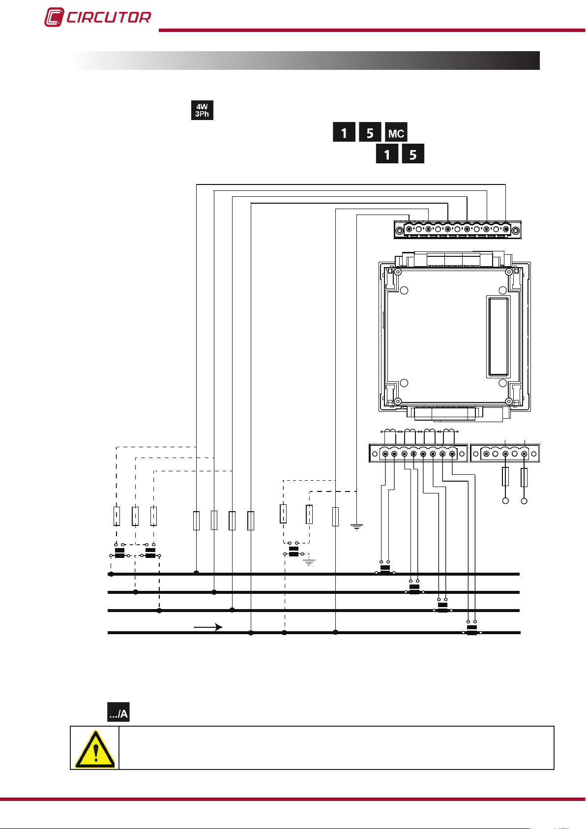
3.4.1.- Three-phase network measurement with a 4-wire connection.
Measurement system:
Secondary winding of the current transformer: (MC1 type transformer)
Secondary winding of the neutral current transformer:
P1 P2
L1
S1 S2
NV
REF REF
P1 P2P1 P2
L2
S1 S2
S1 S2
N V
L3 L2VL1
P1 P2
LN
L3
S1 S2
V
POWER SUPPLY
~
~
+ -
VL1 VL2 VL3
b
a
A B
L1
L2
L3
N
VL1
VL2
VL3 N
a
b
B
A
NREF
a
A
LOAD
VREF
B
NREF
VREF
b
S1
S2
P1
P2
S1
S2
P2
P1
S1
S2
P2
P1
S1
P1
Power
Supply
S2
P2
Figure 3: Three-phase measuring with a 4-wire connection (transformer secondary: /1A, /5A or MC1 (/0.250)).
NB: The unit can calculate the neutral current without having to measure it, option: Calculated
current
.
The MC1 transformer secondary value is set to 0.250 A
The transformer for measuring the LN neutral current cannot be MC type.
14
Instruction Manual
Page 15
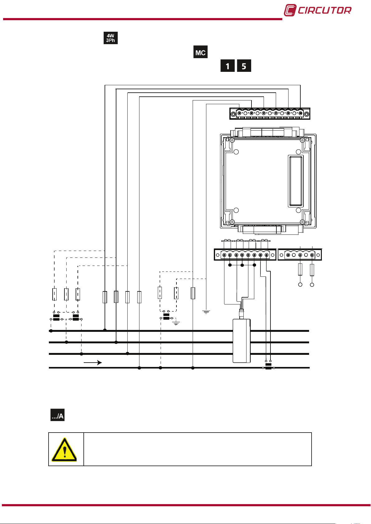
CVM-B100 - CVM-B150
Measurement system:
Secondary winding of the current transformer: (MC3 type transformer)
Secondary winding of the neutral current transformer:
P1 P2
L1
S1 S2
NV
REF REF
P1 P2P1 P2
L3
L2
S1 S2
S1 S2
N V
P1 P2
LN
S1 S2
L3 L2VL1
V
POWER SUPPLY
~
+ -
~
NREF
VREF
NREF
VL1 VL2 VL3
a
b
a
A B
A
VL1
VL2
VL3 N
a
b
B
b
A
B
VREF
Grey/Pink
Red/Blue
Brown/Green
Green/White
Power
Supply
L1
L2
L3
LOAD
N
2P1 1P1
3P1
2P2 1P2
3P2
S1
S2
P2
P1
Figure 4: Three-phase measuring with a 4-wire connection (MC3 type transformer (/0.250)).
NB: The unit can calculate the neutral current without having to measure it, option: Calculated
current .
The MC3 transformer secondary value is set to 0.250 A.
The transformer for measuring the LN neutral current cannot be
MC type.
Instruction Manual
15
Page 16
CVM-B100 - CVM-B150
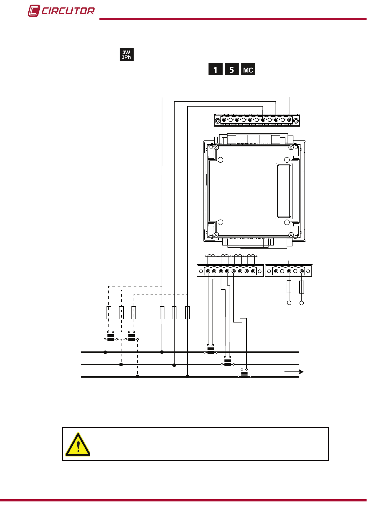
3.4.2.- Three-phase network measurement with a 3-wire connection.
Measurement system:
Secondary winding of the current transformer: (MC1 type transformer)
N V
NV
REF REF
L3 L2VL1
V
P1 P2
P1 P2 P1 P2
L1
S1 S2 S1S2S1
L2
P1 P2
LN
L3
S2
S1 S2
POWER SUPPLY
~
~
+ -
VL1 VL2 VL3
Power
Supply
L1
L2
L3
a
A B
b
b
a
A B
VL1 VL2
VL3
S1
S2
P2
P1
S1
S2
P2
P1
S2
S1
P1
LOAD
P2
Figure 5: Three-phase measuring with a 3-wire connection (transformer secondary: /1A, /5A or MC1 (/0.250)).
16
The MC1 transformer secondary value is set to 0.250 A
Instruction Manual
Page 17
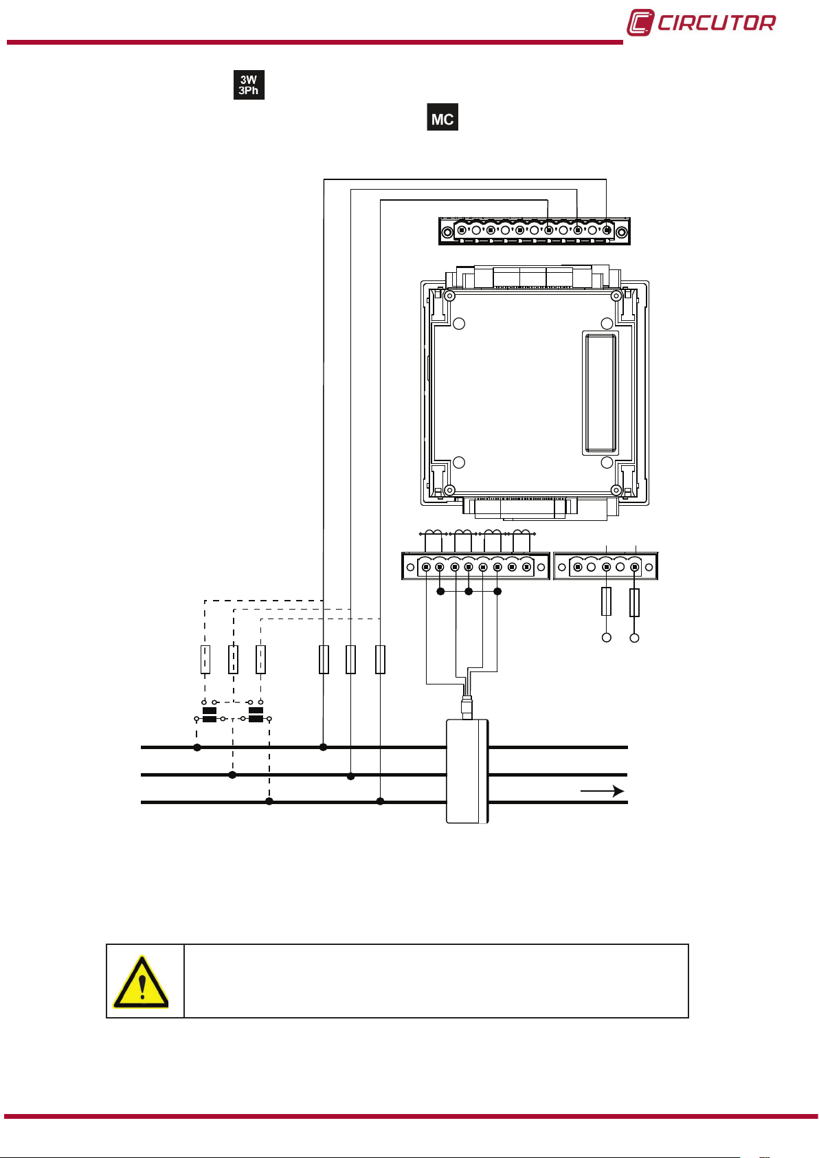
CVM-B100 - CVM-B150
Measurement system:
Secondary winding of the current transformer: (MC3 type transformer)
N V
NV
REF REF
L3 L2VL1
V
P1 P2
S1
P1 P2 P1 P2
L1
S1
S2
P2
P1
LN
L3
L2
S2
S1 S2
S1 S2
POWER SUPPLY
~
~
+ -
VL1 VL2 VL3
Power
Supply
L1
L2
L3
VL1 VL2
VL3
Grey/Pink
b
a
A
B
a
A B
b
Green/White
2P1 1P1
Red/Blue
Brown/Green
2P2 1P2
LOAD
3P1
3P2
Figure 6: Three-phase measuring with a 3-wire connection (MC3 type transformer (/0.250)).
Instruction Manual
The MC3 transformer secondary value is set to 0.250 A
17
Page 18
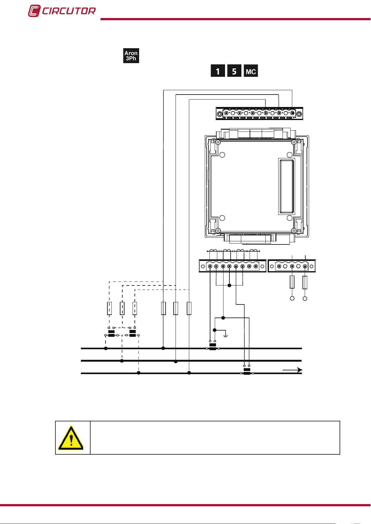
CVM-B100 - CVM-B150
3.4.3.- Three-phase network measurement with a 3-wire connection and transformers with an ARON connection.
Measurement system:
Secondary winding of the current transformer: (MC1 type transformer)
N V
N
V
REF REF
L3 L2VL1
V
P2
P1 P2
P1
P2
P1
P1
L3
L2
L1
S2
S1
S1 S2
S1
P2
LN
S2
S1 S2
POWER SUPPLY
~
~
+ -
VL1 VL2 VL3
Power
Supply
L1
a
A B
b
a
A B
b
VL1 VL2
VL3
S1 S2
P1
P2
L2
S2
L3
S1
P1
LOAD
P2
Figure 7: Three-phase measuring with a 3-wire connection and transformers in an ARON connection (transformer
secondary: /1A, /5A or MC1 (/0.250)).
18
The MC1 transformer secondary value is set to 0.250 A
Instruction Manual
Page 19

CVM-B100 - CVM-B150
3.4.4.- Two-phase network measurement with a 3-wire connection.
Measurement system:
Secondary winding of the current transformer: (MC1 type transformer)
Secondary winding of the neutral current transformer:
N V
NV
REF REF
L3 L2VL1
V
P1 P2
L1
L2
N
VL1
a
A B
P1 P2 P1 P2
L1
L2
S1 S2
S1 S2
VL2
N
a
b
A
VL1
b
B
VL2
N
NREF
VREF
a
A
NREF
VREF
b
B
S1
S2
P1
P2
S1
P1
LOAD
L3
S1 S2
S2
P2
P1 P2
LN
S1 S2
POWER SUPPLY
~
~
+ -
Power
Supply
S1
S2
P2
P1
Figure 8: Two-phase measuring with a 3-wire connection (transformer secondary: /1A, /5A or MC1 (/0.250)).
NB: The unit can calculate the neutral current without having to measure it, option: Calculated
current .
The MC1 transformer secondary value is set to 0.250 A
The transformer for measuring the LN neutral current cannot be MC type.
Instruction Manual
19
Page 20
CVM-B100 - CVM-B150
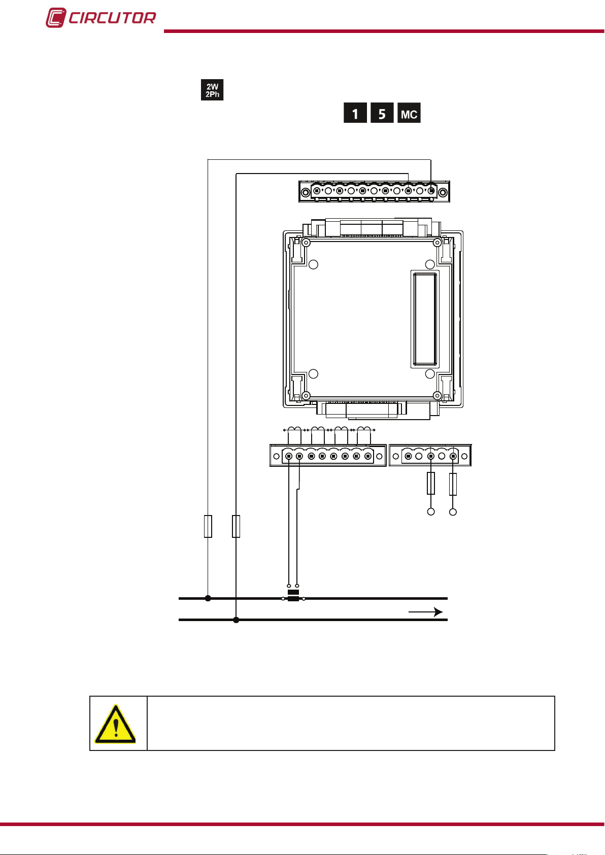
3.4.5.- Single-phase network measurement, phase to phase, with a 2-wire connection.
Measurement system:
Secondary winding of the current transformer: (MC1 type transformer)
N V
NV
REF REF
L3 L2VL1
V
P2
P1
P2
LN
L3
S2
S1
S2
S1
POWER SUPPLY
~
~
+ -
Power
Supply
LOAD
L1
L2
VL1
VL2
P1
L1
S1 S2
S1 S2
P1
P2
P1 P2 P1
S1 S2
P2
L2
Figure 9: Phase to phase single-phase measuring with a 2-wire connection (transformer secondary: /1A, /5A or MC1
(/0.250)).
20
The MC1 transformer secondary value is set to 0.250 A
Instruction Manual
Page 21
CVM-B100 - CVM-B150
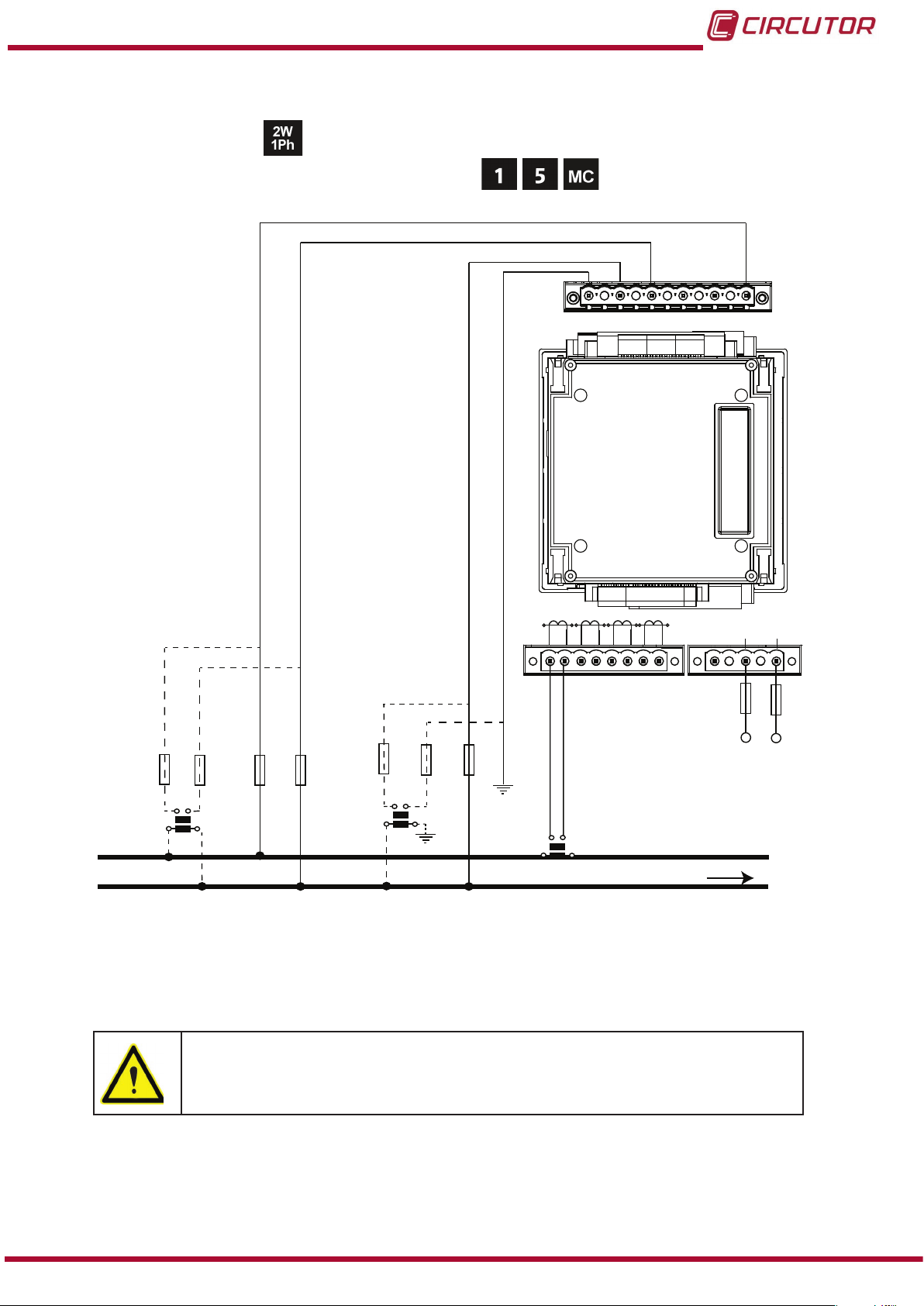
3.4.6.- Single-phase network measurement, phase to neutral, with a 2-wire connection.
Measurement system:
Secondary winding of the current transformer: (MC1 type transformer)
N V
NV
REF REF
L3 L2VL1
V
P1 P2
L1
P1 P2P1 P2
L1
L2
S1 S2
S1 S2
VL1
N
a
b
A
VL1
B
N
NREF
VREF
NREF
VREF
a
b
A
B
S1
S2
P1
P2
N
L3
S1 S2
P1 P2
LN
S1 S2
LOAD
POWER SUPPLY
~
~
+ -
Power
Supply
Figure 10: Phase to neutral single-phase measuring with a 2-wire connection (transformer secondary: /1A, /5A or
MC1 (/0.250)).
The MC1 transformer secondary value is set to 0.250 A
Instruction Manual
21
Page 22
3.5.- STARTING UP THE UNIT
CVM-B100 - CVM-B150
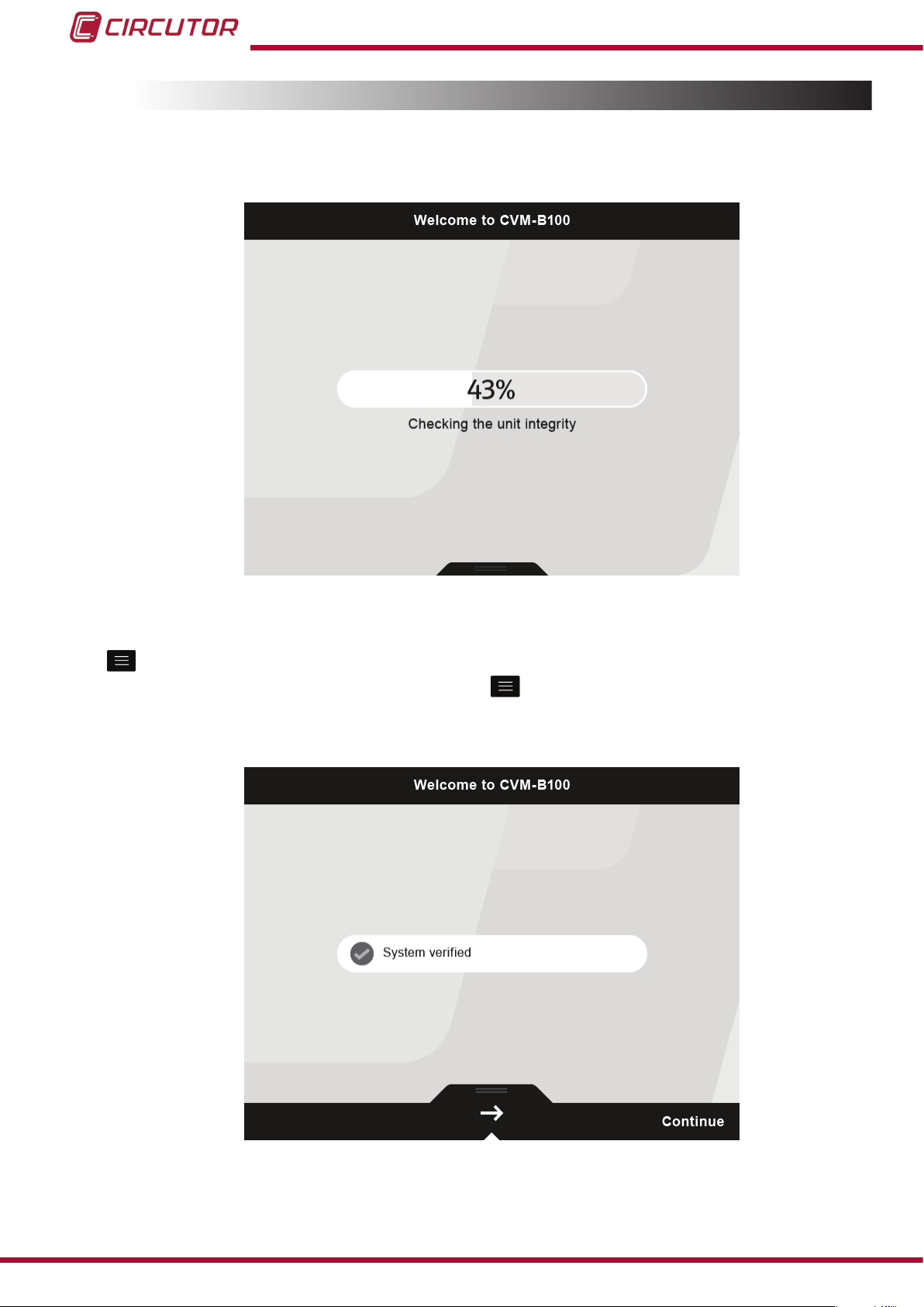
Once the CVM-B is connected to the power supply, the following screen,
Figure 11, appears on
the display and checks the integrity of the unit and detects the expansion modules.
Figure 11: Initial check screen of the CVM-B.
When the checking process has nished, the welcome screen is displayed (Figure 12) until the
key is pressed to continue with the start-up.
NB: If 20 seconds elapse without pressing the
key, the unit moves directly to the measure-
ment screen by default.
22
Figure 12: CVM-B welcome screen.
Instruction Manual
Page 23
CVM-B100 - CVM-B150
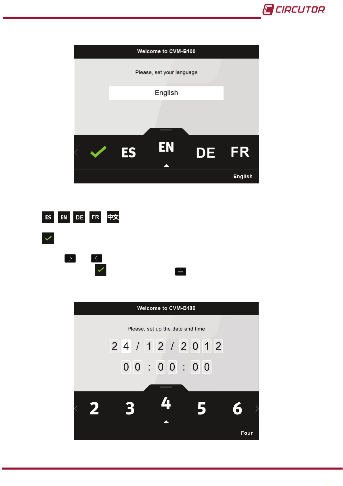
If this is the rst time the unit is switched on, the screen in Figure 13 appears to select the
language.
Figure 13: Language selection screen.
The following options appear in the lower area:
, , , , the possible languages of the unit: Spanish, English, German
French and Chinese.
Conrm, conrms and saves in the memory the language displayed on the screen.
Use the keys
by choosing the option
and to select the required language; once selected, conrm the language
and pressing the key .
After selecting the language, select the current date ( Format: dd/mm/yyyy) and time
(
Figure 14).
Instruction Manual
Figure 14: Current date and time selection screen.
23
Page 24
The digit selected is indicated in white.
The following options appear in the lower area:
CVM-B100 - CVM-B150
Use the keys
choosing the option
, ... the ten possible digits to program.
Previous, selects the previous digit.
Next, selects the next digit.
Conrm date and time, conrms and saves in the memory the value programmed
on the screen
.
and to select the current date and time; once selected, conrm by
and pressing the key .
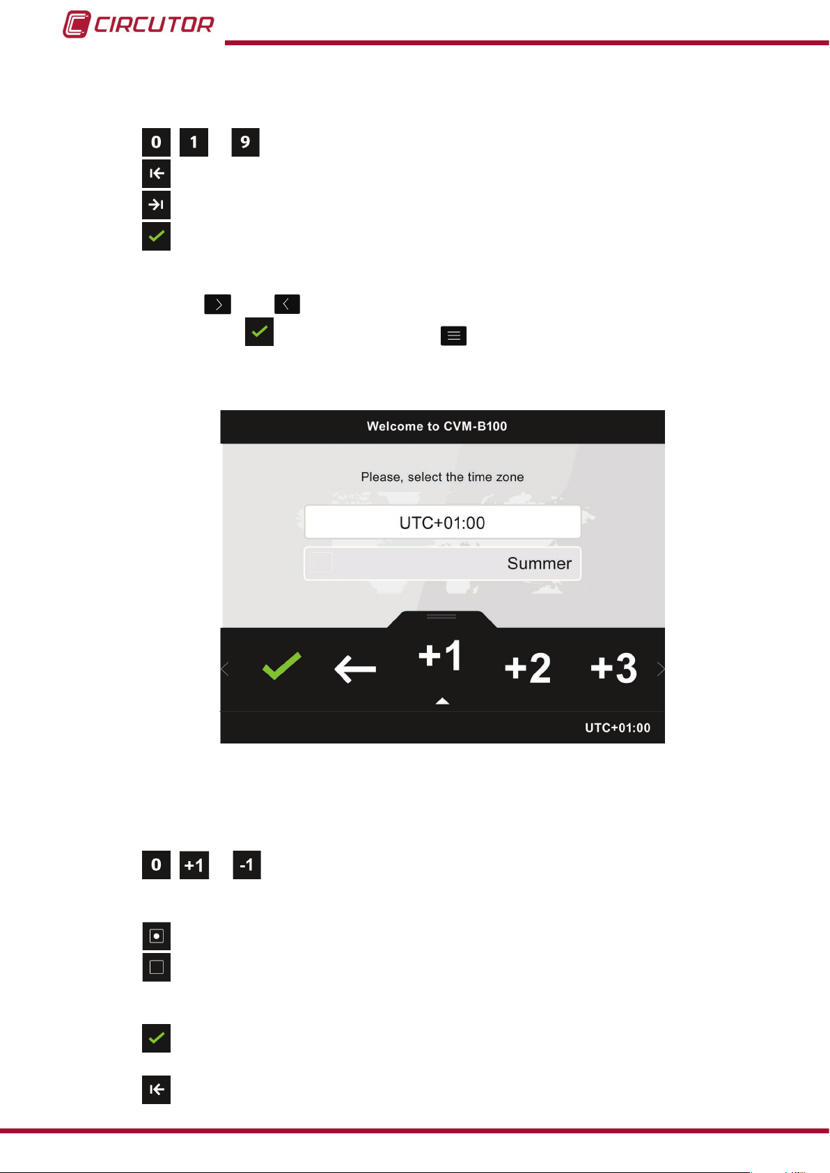
Finally, select the corresponding time zone for the unit, Figure 15.
24
Figure 15: Time zone selection screen.
The following options appear in the lower area:
● When programming the time zone:
, ... all possible time zones.
● When selecting summer/winter time:
Enable summer time.
Disable summer time.
● For all parameters:
Confirm, confirms and saves in the memory the time zone displayed on the
screen
.
Previous, selects the previous parameter.
Instruction Manual
Page 25
CVM-B100 - CVM-B150
Next, selects the next parameter.
Use the keys and to select the different options; once selected, conrm by choosing
the option
and pressing the key .
The screen shown in
Figure 16 will then be displayed for a few seconds,
Figure 16: Start-up screen, CVM-B.
the unit completes its start-up and the main screen is shown on the display, Figure 17.
Instruction Manual
Figure 17: Main screen, CVM-B.
25
Page 26
0º
90º
180º
-90º
Capacitive
Capacitive
Inductive
Inductive
Generation
Power
Consumption
Power
Single-phaseThree-phase
Single-phase
Single-phase
Single-phase
Three-phase
Three-phase
Three-phase
k
k
k
k
k
k
k
k
k
k
k
k
k
k
k
k
k
k
k
k
CVM-B100 - CVM-B150
4.- OPERATION
4.1.- OPERATING PRINCIPLE
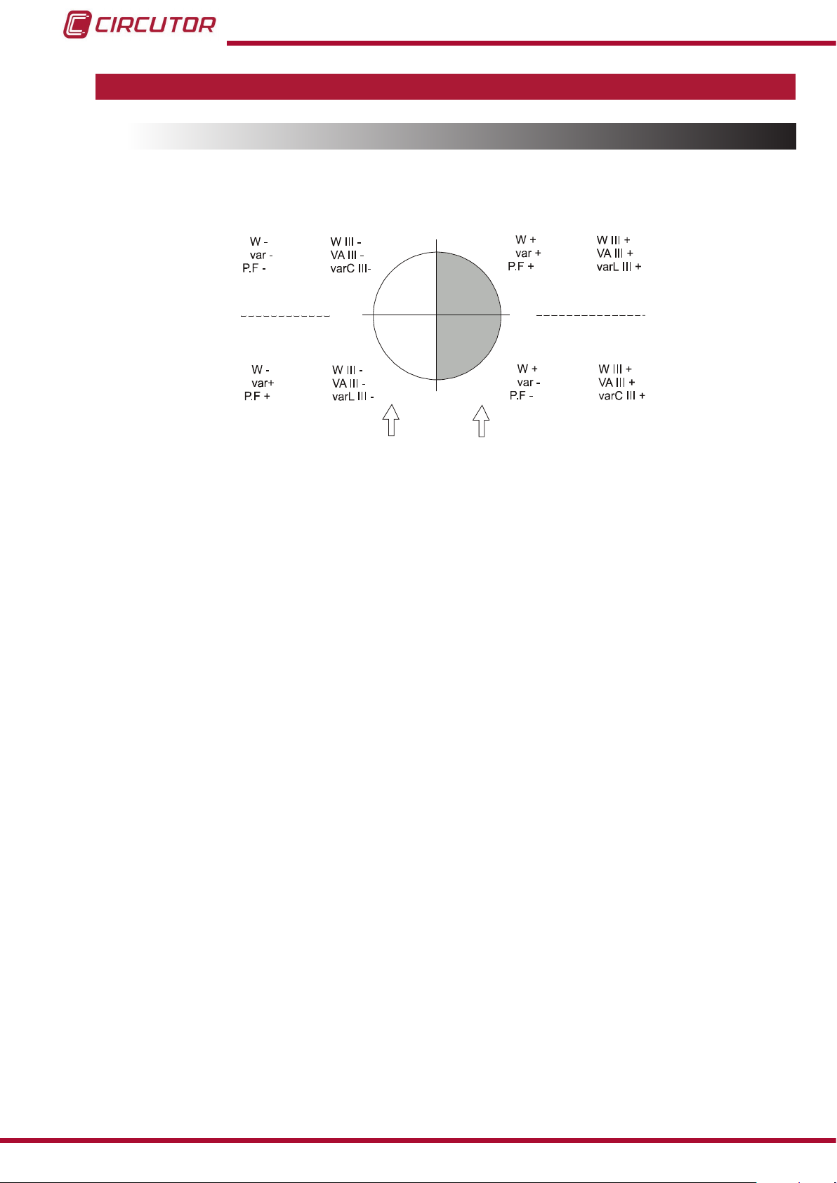
The CVM-B is a four-quadrant power analyzer (consumption and generation).
Figure 18: Four quadrants of CVM-B.
Apart from the basic functions of any analyzer, the CVM-B:
Has, for each instantaneous variable, a bar chart that shows the current instantaneous val-
ue, maximum and minimum values and the pre-alarm and alarm zones programmed.
Has three display modes, in order to display 1, 3 or 4 variables at the same time on each
display. The display of the variables is fully congurable.
It includes as standard the BACnet communications protocol.
It is 100% modular and expandable with different expansion modules which can be includ-
ed in the unit.
It can be easily updated through the microSD card supplied with the unit.
26
Instruction Manual
Page 27

CVM-B100 - CVM-B150
4.2.- MEASUREMENT PARAMETERS
The unit displays the electrical parameters shown in
Table 5: CVM-Bx measurement parameters.
Parameter Units
Phase-neutral voltage Vph-N
Phase-phase voltage Vph-ph
Current A
Frequency Hz
Active Power kW
Apparent Power kVA
Total Reactive Power kvar
Inductive Reactive Power kvarL
Capacitive Reactive Power kvarC
Power factor PF
Cos φ φ
Voltage THD % % THD V
Current THD % % THD A
Harmonic Breakdown - Voltage
(up to the 50th order harmonic)
Harmonic Breakdown - Current
(up to the 50th order harmonic)
Total Active Energy kWh
Total Inductive Reactive Energy kvarLh
Total Capacitive Reactive Energy kvarCh
Total Reactive Energy kvarh
Total Apparent Energy kVAh
Active Energy Tariff 1 kWh
Inductive Reactive Energy Tariff 1 kvarLh
Capacitive Reactive Energy Tariff 1 kvarCh
Total Reactive Energy Tariff 1 kvarh
Apparent Energy Tariff 1 kVAh
Active Energy Tariff 2 kWh
Inductive Reactive Energy Tariff 2 kvarLh
Capacitive Reactive Energy Tariff 2 kvarCh
Total Reactive Energy Tariff 2 kvarh
Apparent Energy Tariff 2 kVAh
Active Energy Tariff 3 kWh
Inductive Reactive Energy Tariff 3 kvarLh
Capacitive Reactive Energy Tariff 3 kvarCh
Total Reactive Energy Tariff 3 kvarh
Apparent Energy Tariff 3 kVAh
Maximum Current Demand, Tariff 1 A
Maximum Active Power Demand, Tariff 1 kW
Table 5.
harm V
harm V
Phases
L1-L2-L3
(L1)
N
Total
III
Instruction Manual
27
Page 28
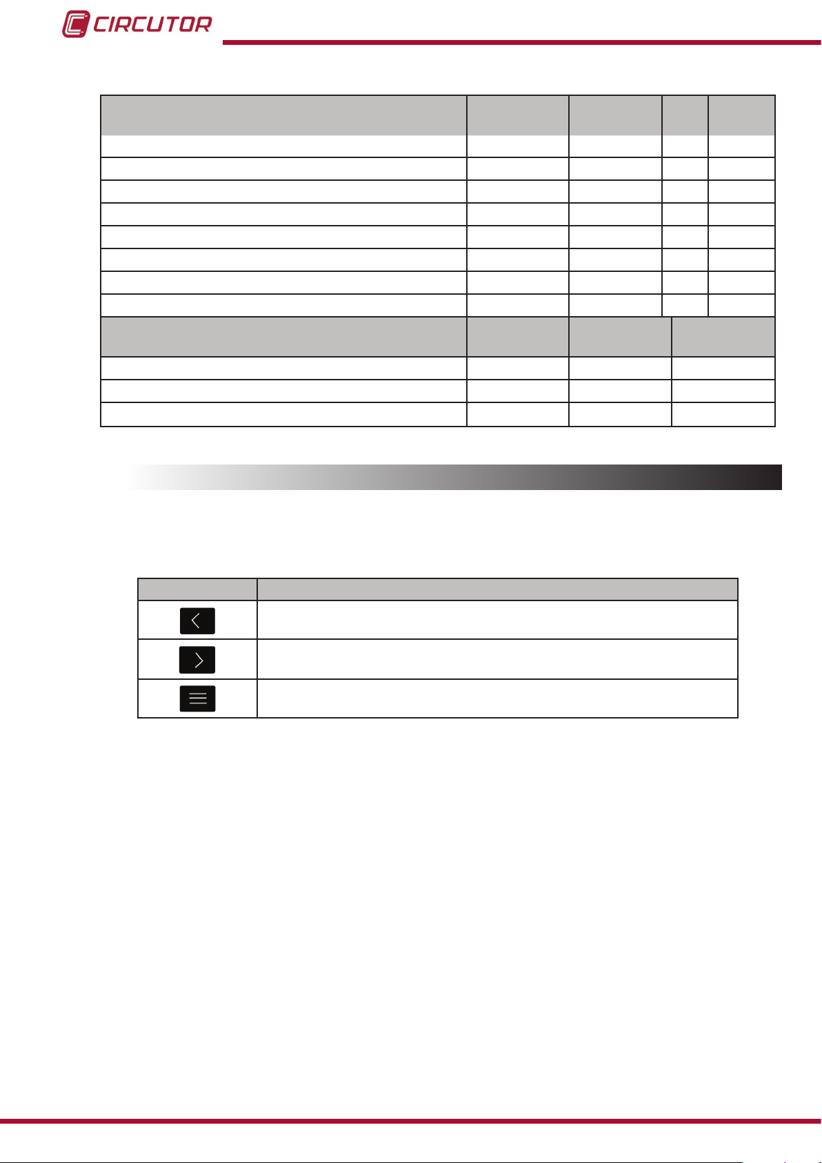
Table 5 ( Continuation ): CVM-Bx measurement parameters.
Parameter Units
Maximum Apparent Power Demand, Tariff 1 kVA
Maximum Current Demand, Tariff 2 A
Maximum Active Power Demand, Tariff 2 kW
Maximum Apparent Power Demand, Tariff 2 kVA
Maximum Current Demand, Tariff 3 A
Maximum Active Power Demand, Tariff 3 kW
Maximum Apparent Power Demand, Tariff 3 kVA
Phase sequence
Parameter Units
No. of hours of active tariff hours
Cost COST
CO
Emissions kgCO
2
CVM-B100 - CVM-B150
Phases
L1-L2-L3
N
Total
III
Tariff:
T1-T2-T3
Total Tariff
2
4.3.- KEYPAD FUNCTIONS
The CVM-B has 3 keys that allow you to browse the various screens and program the unit.
Table 6: Function of keys.
Key Keystroke
Shifting to the left
Shifting to the right
Select parameter / Enter programming menu
28
Instruction Manual
Page 29
CVM-B100 - CVM-B150
4.4.- DISPLAY
The unit has a colour TFT display which displays all the parameters indicated in Table 5.
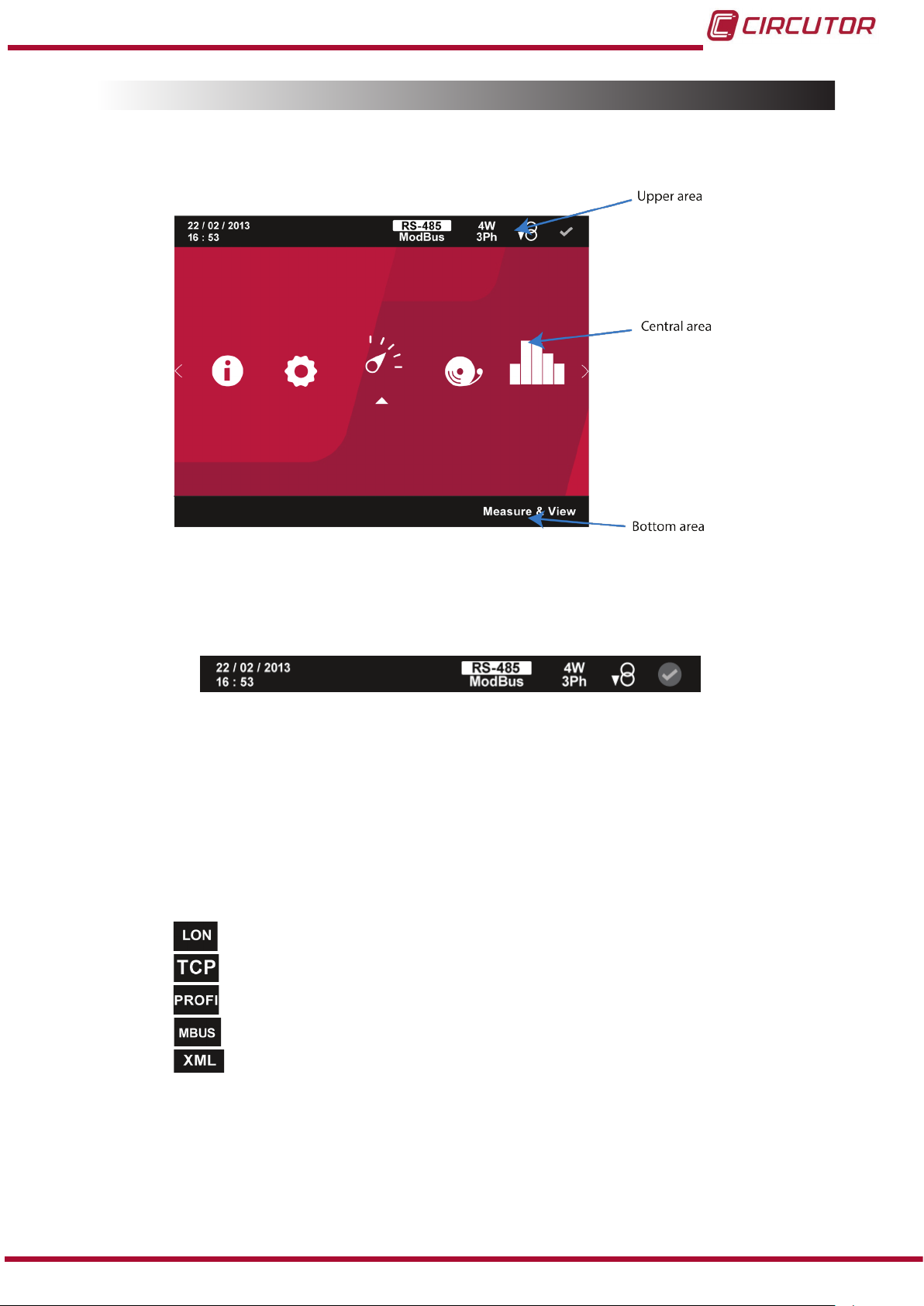
The display is divided into three areas (
Figure 19):
Figure 19: CVM-B display areas.
4.4.1.- UPPER AREA
Figure 20: Upper area of display.
The current date and time are displayed in real time in this area.
The following are also displayed:
Communications expansion module
If a communications expansion module has been installed, one of the following messages will be displayed according to the purpose of the module:
LonWorks Module
Modbus/TCP Module.
Probus Module.
Instruction Manual
MBus Module.
Datalogger Module.
29
Page 30

CVM-B100 - CVM-B150
Type of communications
The CVM-B units have one RS-485 communications port.
The unit has as standard two communications protocols: MODBUS RTU ® and BACnet.
See “6.- INTEGRATED COMMUNICATIONS”
Depending on the protocol selected you will view:
MODBUS RTU protocol.
BACnet protocol.
Type of installation
Use the setup menu to select the type of installation to which the unit is connected,
(“5.6.5.- Measurement connection mode.”).
Depending on the installation selected, you will view:
Single-phase installation.
Two-phase installation.
Two-phase installation with neutral.
Three-phase installation.
Three-phase installation with neutral.
Aron installation.
If the position of the input channels is changed to allow communications ( “6.3.7.17.- Po-
sition of input channels”
), the installation type will be shown in red.
Consumption or Generation
The icon
The icon
indicates that the installation is generating.
indicates that the installation is consuming.
Alarm status
The icon
The icon
The icon
indicates that no alarm has been generated.
indicates that the unit has a pre-alarm activated.
indicates that the unit has an alarm activated.
30
Instruction Manual
Page 31

CVM-B100 - CVM-B150
4.4.2.- LOWER AREA
Figure 21: Lower area of display.
The various options on the display and setup menus and an explanatory text for the option selected are shown in the lower area.
On the display screens the lower area disappears after 3 seconds without pressing any key.
It reappears by pressing the key
.
4.4.3.- CENTRAL AREA
The different display and setup menus for the unit are accessed from the central area.
All instantaneous, incremental and demand parameters in various formats are also displayed:
Numeric representation of one, three and up to four parameters at the same time.
Analogue representation.
Graphical representation.
Representation on a bar chart.
A bar chart is displayed for instantaneous and demand parameters, Figure 22, which shows the
current instantaneous value, maximum and minimum values and pre-alarm and alarm zones
programmed.
Instruction Manual
Figure 22: Description of the bar chart.
31
Page 32

CVM-B100 - CVM-B150
If an alarm has not been programmed for the parameter, the pre-alarm and alarm zones shown
in the bar chart are calculated.
Figure 23: Calculation of the bar chart.
The calculation formulas are:
Neutral-phase voltage and neutral voltage
L = Primary rated voltage* 0.9 H= Primary rated voltage * 1.1
Min = L * 0.8 Max = H * 1.2
PL = L + (( H - L) * 0.1) PH = H - (( H - L) * 0.1)
Phase-phase voltage
L = Primary rated voltage* 0.9 * √3 H = Primary rated voltage * 1.1 * √3
Min = L * 0.8 Max = H * 1.2
PL = L + (( H - L) * 0.1) PH = H - (( H - L) * 0.1)
Current
L = 0 H = Primary current
Min = 0 Max = H * 1.2
PL = 0 PH = H - (( H - L) * 0.1)
The alarm and pre-alarm zones L are not displayed.
Power ratings
L = 0 H = Primary rated voltage * Primary current
Min = 0 Max = H * 1.2
PL = 0 PH = H - (( H - L) * 0.1)
32
The alarm and pre-alarm zones L are not displayed.
Frequency 50 Hz
L = 45 H = 55
Min = L * 0.95 Max = H * 1.05
PL = L + (( H - L) * 0.25) PH = H - (( H - L) * 0.25)
Instruction Manual
Page 33

CVM-B100 - CVM-B150
Frequency 60 Hz
L = 55 H = 65
Min = L * 0.95 Max = H * 1.05
PL = L + (( H - L) * 0.25) PH = H - (( H - L) * 0.25)
Voltage THD
L = 0 H = 5
Min =0 Max = H * 2
PL = L + (( H - L) * 0.25) PH = H - (( H - L) * 0.25)
The alarm and pre-alarm zones L are not displayed.
Current THD
L = 0 H = 20
Min =0 Max = H * 2
PL = L + (( H - L) * 0.25) PH = H - (( H - L) * 0.25)
The alarm and pre-alarm zones L are not displayed.
Cosine phi and Power factor
L = -0.9 H = 0.9
Min = -Max Max = minor(L or H) * 1.2
PL = L + (( L - H+2) * 0.25) PH = H + (( L - H+2) * 0.25)
Instruction Manual
33
Page 34

4.5.- LED INDICATORS
The CVM-B unit features:
- A CPU LED, which indicates that the unit is working correctly with a 1 second ashing.
A ashing of 0.5 seconds indicates that an error has occurred.
- An ALARM LED, which indicates that an alarm has been activated with the LED ash-
ing. If there is no alarm it remains switched off.
-3 LED on the navigation keys, which stay switched on with low current; when any of
the 3 keys are pressed they all come on at maximum current.
CVM-B100 - CVM-B150
KEYSCPU
Figure 24:LED indicators of the CVM-B.
ALARM
34
Instruction Manual
Page 35

CVM-B100 - CVM-B150
4.6.- INPUTS
The CVM-B has two programmable digital inputs (terminals 7 and 8 in
Figure 1) for working as:
Logic input.
Impulse input.
Tariff selection.
See “5.6.17.- Digital inputs.” to congure the inputs.
In “5.1.7.- Integrated functions.” and in “5.5.2 Integrated functions.” you can see the status and
conguration of the programmed digital inputs.
The selected tariff can be determined in accordance with the status of the inputs, as shown in
Table 7.
Table 7: Selecting the tariff according to the inputs.
I1 I2
Tariff selection Tariff selection
0 0 Tariff 1
0 1 Tariff 2
1 0 Tariff 3
Tariff
4.7.- OUTPUTS
The unit features:
Two relay digital outputs (terminals 16, 17, 18 and 19 in
Figure 1) programmable as
alarms, see “5.6.15.-Relay digital outputs.”
Two transistor digital outputs, optoisolated NPNs (terminals 10, 11 and 12 in
Figure 1) programmable as an impulse output or alarms, see “5.6.16.- Transistor digital
outputs.”
Instruction Manual
35
Page 36

5.- DISPLAY AND CONFIGURATION
CVM-B100 - CVM-B150
On the main screen,
Figure 25, you can access the various menus of the unit:
Figure 25:Main screen.
Measurement display menu, see “5.1.-MEASUREMENT DISPLAY MENU ”
Alarm menu, see “5.2.- ALARM MENU ”.
Energy closes menu, see “5.3.- ENERGY CLOSES MENU ”
Log menu, see “5.4.- LOG MENU ”
Information menu, see “5.5.- INFORMATION MENU ”.
Setup menu, see “5.6.- SETUP MENU ”.
Use the keys and to browse the various menus.
To access the selected menu press the key
.
If no key is pressed for 5 minutes, the display screen changes automatically to the default
screen, which displays the voltage measurement of 4 parameters.
36
Instruction Manual
Page 37

CVM-B100 - CVM-B150
5.1.-MEASUREMENT DISPLAY MENU
The screen in Figure 26 is the home screen for the measurement display menu.
Figure 26: Main screen of the measurement display menu.
The display options appear in the lower area:
Display 1 parameter.
Display 3 parameters.
Display 4 parameters.
Phasors.
Standardised phasors.If the congured connection mode is single-phase or twophase without neutral, the normalised phasors icon is not displayed.
Harmonics
Integrated functions.
Expansion modules. This option only appears when the unit is connected to an
an expansion module of Transistor Digital Inputs/Outputs (M-CVM-AB-8I-8OTR),
Relay Digital Inputs/Outputs (M-CVM-AB-8I-8OR) or Analogue Inputs/Outputs
(M-CVM-AB-4AI-8AO).
Use the keys
To access the selected menu press the key
Main menu, return to the main menu, Figure 25.
and to browse the various menus.
.
If no key is pressed for 5 minutes, the display screen changes automatically to the default
screen, which displays the voltage measurement of 4 parameters.
Instruction Manual
37
Page 38

CVM-B100 - CVM-B150
5.1.1.- Display 1 parameter.
By selecting this option, you want to view a single parameter on the display.
Figure 27: 1 parameter display screen.
The following options appear in the lower area:
Default parameters.
Customise parameters.
Back, returns to the home screen of the measurement display menu, Figure 26
Main Menu, back to the main menu, Figure 25.
Use the keys
To access the selected menu press the key
and to browse the various menus.
.
If no key is pressed for 5 minutes, the display screen changes automatically to the default
screen, which displays the voltage measurement of 4 parameters.
38
Instruction Manual
Page 39

CVM-B100 - CVM-B150
5.1.1.1.- Default parameters.
This menu allows you to view the following types of parameters:
Figure 28:Default parameters display screen (display 1 parameter).
Instantaneous parameters.
Incremental parameters.
Demand parameters.
Back, returns to the home screen of the 1 parameter display menu, Figure 27.
Main Menu, back to the main menu, Figure 25.
Use the keys
To access the selected menu press the key
and to browse the various menus.
.
If no key is pressed for 5 minutes, the display screen changes automatically to the default
screen, which displays the voltage measurement of 4 parameters.
Instruction Manual
39
Page 40

CVM-B100 - CVM-B150
5.1.1.1.1.- Instantaneous parameters.
On this screen, Figure 29, you can view all the parameters indicated in Tabla 8.
Figure 29: Instantaneous parameters (display 1 parameter).
For each of the instantaneous parameters you can view:
The maximum and minimum value, with the date and time when it occurred.
A bar chart with the indications of the instantaneous value, maximum and minimum
values and alarms, see “4.4.3. CENTRAL AREA”.
Graphical representation of the parameter.
The analogue representation of the parameter.
Table 8: Instantaneous parameters.
Icon
Phase-Neutral Voltage
Neutral voltage
Phase-Phase Voltage
Current
Display 1 parameter
Instantaneous parameters
40
Neutral Current
Frequency
Active power
(1)
Inductive reactive power
Capacitive reactive power
(1)
(1)
Instruction Manual
Page 41

CVM-B100 - CVM-B150
Table 8 ( Continuation) : Instantaneous parameters.
Icon
Display 1 parameter
Instantaneous parameters
Total reactive power
Apparent power
Power factor
Cosine phi III
Voltage THD
Current THD
(1)
The following icons appear for all these parameters on the screen:
Indicating that the parameter refers to inductive or capacitive energy.
Indicating that the parameter refers to consumed or generated energy.
(1)
(1)
(1)
(1)
(1)
(1)
If the 2 icons light up at the same time, it means the installation is not properly connected.
Use the keys
and to browse the various parameters.
If there is an alarm associated with the variable being displayed, the following will be shown:
The module with which the alarm is associated.
The associated output in the module.
The alarm status: not activated, pre-alarm activated, alarm activated.
The icon flashes during the delay time in the alarm connection (ON) and
disconnection (OFF).
The menu in the lower area disappears after 3 seconds (
Figure 30).
Instruction Manual
41
Page 42

CVM-B100 - CVM-B150
Figure 30: Instantaneous parameters without lower area (display 1 parameter).
Press the key to display the lower area again.
The following icons also appear in the lower area:
Back, returns to the default parameters display screen, Figure 28.
Main Menu, back to the main menu, Figure 25.
If you press the key
while selecting a display parameter, you will enter the parameter
display menu.
5.1.1.1.1.1.- Instantaneous parameters display menu.
For each instantaneous parameter, this menu enables (Figure 31):
42
Figure 31:Instantaneous parameters, display menu (display 1 parameter).
Instruction Manual
Page 43

CVM-B100 - CVM-B150
Graphic view. (“5.1.1.1.1.1.1.Graphic view.”)
Analog view. ( “5.1.1.1.1.1.2. Analog view.”)
Display of 3 parameters, moves to the 3 parameters display screen.
(
“5.1.2.- Display 3 parameters.”)
Display of 4 parameters, moves to the 4 parameters display screen.
“5.1.3.- Display 4 parameters.”)
(
Back, returns to the instantaneous parameters display screen, Figure 29.
Main Menu, back to the main menu, Figure 25.
5.1.1.1.1.1.1.-
Figure 32 shows the graphical display screen.
Graphic view
Figure 32: Instantaneous parameters, graphic view (displays 1 parameter).
The menu in the lower area disappears after 3 seconds.
Press the
key to display the lower area again.
The lower area menu options are:
, , Selecting the graph display time ( X-axis ). The time can be set to 20, 60
or 300 seconds
Note: The option selected is not displayed on the menu.
Back, returns to the instantaneous parameters display menu screen, Figure 31.
Main Menu, back to the main menu, Figure 25.
Use the keys
To access the option selected press the key
Instruction Manual
and to browse the different options.
.
43
Page 44

5.1.1.1.1.1.2.- Analog view.
CVM-B100 - CVM-B150
The analogue display screen is shown in
Figure 33:Instantaneous parameters, analog view(display 1 parameter).
Figure 33.
The menu in the lower area disappears after 3 seconds.
Press the
key to display the lower area again.
The lower area menu options are:
Back, returns to the instantaneous parameters display menu screen, Figure 31.
Main Menu, back to the main menu, Figure 25.
Use the keys
To access the option selected press the key
and to browse the different options.
.
If you view the current, active power or apparent power, a second red coloured needle will
appear indicating the value of the maximum demand of the parameter being displayed.
If there is an alarm associated with the variable being displayed, the following will be shown:
The alarm status:
The module with which the alarm is associated.
The associated output in the module.
not activated, pre-alarm activated, alarm activated.
44
The
icon flashes during the delay time in the alarm connection (ON) and
disconnection (OFF).
Instruction Manual
Page 45

CVM-B100 - CVM-B150
5.1.1.1.2.- Incremental parameters.
On this screen, Figure 34, you can view all the parameters indicated in Tabla 9.
For each of the incremental parameters you can view:
The value generated and consumed,
The value for each tariff, T1, T2 and T3 and the total value of the 3 tariffs.
The graphical representation of the parameter.
Graphical representation of the energy closes.
Figure 34: Incremental parameters (display 1 parameter).
Table 9:Incremental parameters (display 1 parameter).
Icon
Active energy
Inductive reactive energy
Capacitive reactive energy
Total reactive energy
Apparent energy
Display 1 parameter
Incremental parameters
(1) (2)(3)
(1) (2) (3)
(1) (2) (3)
(1) (2) (3)
(1) (2) (3)
Active tariff hours
CO2 Emissions
Cost
(1)
There is a graphical representation for all these parameters on the screen, Figure 35, which
indicates the energy increase: a at line indicates that there is no energy increase and the pulses indicate an increase in it.
Instruction Manual
45
Page 46

CVM-B100 - CVM-B150
Figure 35: Graphical representation of the energy increase.
NB: This representation is not real, it is only signicant to give the user an idea of the energy
increase.
(2)
The following icons appear for all these parameters on the screen:
Indicating that the parameter refers to consumed or generated energy.
If the 2 icons light up at the same time, it means the installation is not properly connected.
(3)
The value of the energy parameters is saved in the non-volatile memory every minute.
Press the
Use the keys
key to display the lower area.
and to browse the various parameters.
The menu in the lower area disappears after a few seconds.
The following icons also appear in the lower area:
Back, returns to the default parameters display screen, Figure 28.
Main Menu, back to the main menu, Figure 25.
If there is a transistor digital output or input, programmed in impulse mode, associated with the
variable being displayed, the following will appear:
The icon that indicates that an impulse input or output has been programmed
The module with which the alarm is associated.
The associated output in the module.
If you press the key
while selecting a display parameter, you will enter the parameter
display menu.
46
Instruction Manual
Page 47

CVM-B100 - CVM-B150
5.1.1.1.2.1.- Incremental parameters display menu.
For each incremental parameter, this menu enables the following (Figure 36):
Figure 36: Incremental parameters, display menu (display 1 parameter).
Display the generation or consumption value of the selected parameter.
NB: The option selected is not displayed on the menu.
Tariff selection (“5.1.1.1.2.1.1. Tariff selection)
Graphic view of the incremental energy parameters. (“5.1.1.1.2.1.2. Graphic view”)
Back, returns to the incremental parameters display screen, Figure 34.
Main Menu, back to the main menu, Figure 25.
Instruction Manual
47
Page 48

5.1.1.1.2.1.1.- Tariff selection.
CVM-B100 - CVM-B150
The screen for selecting the tariff to be displayed is shown in
Figure 37:Incremental parameters, tariff selection (display 1 parameter).
Figure 37.
The menu in the lower area disappears after 3 seconds.
Press the
key to display the lower area again.
The lower area menu options are:
, , , Select the tariff to display: Tariff 1, Tariff 2, Tariff 3 or the total value
of the three tariffs.
NB: The option selected is not displayed on the menu.
Back, returns to the incremental parameters display menu, Figure 36.
Main Menu, back to the main menu, Figure 25.
Use the keys
To access the option selected press the key
and to browse the different options.
.
48
Instruction Manual
Page 49

CVM-B100 - CVM-B150
5.1.1.1.2.1.2.- Graphic view
The graphical representation of the energy closes is shown for all the incremental energy
parameters, Figure 38.
Figure 38:Incremental parameters, graphic view (displays 1 parameter).
The menu in the lower area disappears after 3 seconds.
Press the
key to display the lower area again.
The lower area menu options are:
, , , Selecting the energy close time periods: Closes of 1 hour, 12 hours
24 hours or 30 days.
Note: The option selected is not displayed on the menu.
Previous, scrolls through the energy closes in ascending order.
Next, scrolls through the energy closes in descending order.
Back, returns to the incremental parameters display menu, Figure 36.
Main Menu, back to the main menu, Figure 25.
Use the keys
To access the option selected press the key
and to browse the different options.
.
The unit shows 59 energy closes for each display period.
The energy close values are reset when the unit is disconnected from the auxiliary power supply.
Instruction Manual
49
Page 50

CVM-B100 - CVM-B150
5.1.1.1.3.- Demand parameters.
On this screen, Figure 39, you can view all the maximum demand parameters indicated in
Tabla 10.
For each of the demand parameters you can view:
Graphical representation of the parameter.
The analogue representation of the parameter.
The value for each tariff, T1, T2 and T3.
A bar chart with the indications of the instantaneous value, maximum and minimum
values and alarms, see “4.4.3. CENTRAL AREA”.
Figure 39: Demand parameters (display 1 parameter).
Table 10:Demand parameters (displays 1 parameter).
Icon
Current
Active power
Apparent power
Display 1 parameter
Demand parameters.
The following icons appear for all these parameters on the screen:
Indicating that the parameter refers to consumed or generated energy.
If the 2 icons light up at the same time, it means the installation is not properly connected.
Use the keys
and to browse the various parameters.
If there is an alarm associated with the variable being displayed, the following will be shown:
The module with which the alarm is associated.
50
Instruction Manual
Page 51

CVM-B100 - CVM-B150
The associated output in the module.
The alarm status: not activated, pre-alarm activated, alarm activated.
The icon flashes during the delay time in the alarm connection (ON) and
disconnection (OFF).
The menu in the lower area disappears after 3 seconds.
Press the
key to display the lower area again.
The following icons also appear in the lower area:
Back, returns to the default parameters display screen, Figure 28.
Main Menu, back to the main menu, Figure 25.
If you press the key
while selecting a display parameter, you will enter the parameter
display menu.
5.1.1.1.3.1.- Demand parameters display menu.
For each demand parameter, this menu enables (Figure 40):
Figure 40:Demand parameters display menu (display 1 parameter).
Graphic view (“5.1.1.1.3.1.1.Graphic view.”)
Analogue display.(“5.1.1.1.3.1.2. Analogue display.”)
Tariff selection (“5.1.1.1.3.1.3. Tariff selection.”)
Back, returns to the demand parameters display screen, Figure 39.
Main Menu, back to the main menu, Figure 25.
Instruction Manual
51
Page 52

5.1.1.1.3.1.1.- Graphic view.
Figure 41 shows the graphical display screen.
CVM-B100 - CVM-B150
Figure 41:Demand parameters, graphic view (displays 1 parameter).
The menu in the lower area disappears after 3 seconds.
Press the
key to display the lower area again.
The lower area menu options are:
, , Select the integration time ( X-axis ) on the graph. The time can be set to 120
minutes or 48 hours.
Note: The option selected is not displayed on the menu.
Back, returns to the demand parameters display menu screen, Figure 40.
Main Menu, back to the main menu, Figure 25.
Use the keys
To access the option selected press the key
and to browse the different options.
.
52
Instruction Manual
Page 53

CVM-B100 - CVM-B150
5.1.1.1.3.1.2.- Analogue view.
The analogue display screen is shown in
Figure 42:Demand parameters, analog view (display 1 parameter).
Figure 42.
The menu in the lower area disappears after 3 seconds.
Press the
key to display the lower area again.
The lower area menu options are:
Back, returns to the demand parameters display menu screen, Figure 40.
Main Menu, back to the main menu, Figure 25.
Use the keys
To access the option selected press the key
and to browse the different options.
.
The second red coloured needle indicates the instantaneous value of the parameter being
displayed.
If there is an alarm associated with the variable being displayed, the following will be shown:
The alarm status:
The module with which the alarm is associated.
The associated output in the module.
not activated, pre-alarm activated, alarm activated.
The
icon flashes during the delay time in the alarm connection (ON) and
disconnection (OFF).
Instruction Manual
53
Page 54

5.1.1.1.3.1.3.- Tariff selection.
The screen for selecting the tariff to be displayed is shown in Figure 43.
CVM-B100 - CVM-B150
Figure 43: Demand parameters, tariff selection (display 1 parameter).
The menu in the lower area disappears after 3 seconds.
Press the
key to display the lower area again.
The lower area menu options are:
, , Select the tariff to display: Tariff 1, Tariff 2 or Tariff 3.
NB: The option selected is not displayed on the menu.
Back, returns to the demand parameters display menu screen, Figure 40.
Main Menu, back to the main menu, Figure 25.
Use the keys
To access the option selected press the key
and to browse the different options.
.
54
Instruction Manual
Page 55

CVM-B100 - CVM-B150
5.1.1.2.- Customise parameters
On this screen, Figure 44, you can view the ve custom screens with 1 parameter.
Figure 44: Custom parameters screen (display 1 parameter).
The menu in the lower area disappears after 3 seconds.
Press the
key to display the lower area again.
The lower area menu options are:
, ... Select one of the 5 programmed custom screens.
Back, returns to the home screen of the 1 parameter display menu, Figure 27.
Main Menu, back to the main menu, Figure 25.
Use the keys
To access the option selected press the key
and to browse the different options.
.
Instruction Manual
55
Page 56

5.1.1.2.1.- , ... Customisation screens
Figure 45 shows the screen used to customise 1 parameter.
These screens can also be congured for communications.
See “6.- INTEGRATED COMMUNICATIONS”.
CVM-B100 - CVM-B150
Figure 45: Custom parameters screen (displays 1 parameter).
The menu in the lower area disappears after 3 seconds.
Press the
key to display the lower area again.
The lower area menu options are:
Select the parameter that will be displayed on the customisation screen.
(“5.1.1.2.1.1. Parameter selection”)
Back, returns to the home screen of the parameter customisation menu, Figure 44.
Main Menu, back to the main menu, Figure 25.
Use the keys
To access the option selected press the key
and to browse the different options.
.
56
Instruction Manual
Page 57

CVM-B100 - CVM-B150
5.1.1.2.1.1.- Parameter selection
Figure 46 shows the screen for selecting the parameter for display.
Figure 46: Custom parameters screen, parameter selection (displays 1 parameter).
The menu in the lower area disappears after 3 seconds.
Press the
key to display the lower area again.
The lower area menu options are:
Selects an instantaneous parameter (“5.1.1.2.1.1.1. Selecting an instantaneous
parameter.”)
Selecting an incremental parameter. (“5.1.1.2.1.1.2. Selecting an incremental
parameter.”
Selecting a demand parameter.(“5.1.1.2.1.1.3. Selecting a demand parameter.”)
)
Delete parameter, deletes the parameter displayed on the screen.
When this option is selected the icon appears with the option to save the deleted
parameter.
Back, returns to the customisation screen, Figure 45.
Main Menu, back to the main menu, Figure 25.
Use the keys
To access the option selected press the key
Instruction Manual
and to browse the different options.
.
57
Page 58

5.1.1.2.1.1.1.- Selecting an instantaneous parameter.
Figure 47 shows the screen for selecting the Instantaneous parameters.
CVM-B100 - CVM-B150
Figure 47: Custom parameters screen, selecting an instantaneous parameter (displays 1 parameter).
The menu in the lower area disappears after 3 seconds.
Press the
key to display the lower area again.
The menu at the bottom displays all the available instantaneous parameters (Table 11).
Table 11: Instantaneous parameters that can be selected on the customisation screens.
Customisation screen
Icon Instantaneous parameter Icon Instantaneous parameter
Phase-Neutral Voltage Total reactive power
Phase-Phase Voltage Apparent power
Current Power factor
Frequency Cosine phi
Active power Voltage THD
Inductive reactive power Current THD
58
Capacitive reactive power
Instruction Manual
Page 59

CVM-B100 - CVM-B150
To select a parameter, press the button to open the menu at the bottom for selecting the
phase:
● For the Neutral-Phase and
Phase L1, Phase L2, Phase L3, Three-phase, Neutral.
● For the Phase-Phase Voltage
Voltage parameters:
parameter:
Phase L1-L2, Phase L2-L3, Phase L1-L3, Phase L1-L2-L3.
● For the Frequency parameter:
Phase L1.
● For the Active power, Inductive reactive power, Capacitive reactive power, Total
reactive power, Apparent power, Power factor and Cosine phi parameters:
Phase L1, Phase L2, Phase L3, Three-phase.
● For the Voltage THD and Current THD parameters:
Phase L1, Phase L2, Phase L3, Neutral.
The option appears after selecting the phase to save the selection.
The following options are also shown on the bottom at all times
Back, returns to the previous customisation screen.
Main Menu, back to the main menu, Figure 25.
Use the keys and to browse the different options.
To access the option selected press the key
.
Instruction Manual
59
Page 60

5.1.1.2.1.1.2.- Selecting an incremental parameter.
Figure 48 shows the screen for selecting an incremental parameter.
CVM-B100 - CVM-B150
Figure 48: Custom parameters screen, selecting an incremental parameter (displays 1 parameter).
The menu in the lower area disappears after 3 seconds.
Press the
key to display the lower area again.
The menu at the bottom displays all the available instantaneous parameters (Table 12).
Table 12: Incremental parameters that can be selected on the customisation screens.
Customisation screen
Icon Incremental parameter Icon Incremental parameter
Active energy
Inductive reactive energy
Capacitive reactive energy CO2 Emissions
Total reactive energy Cost
Apparent energy
Active tariff hours
To select a parameter, press the button to open the menu at the bottom for selecting the
phase:
60
● For the Active energy, Inductive reactive energy, Capacitive reactive energy, Total
reactive energy and Apparent energy parameters:
Phase L1, Phase L2, Phase L3, Three-phase.
Instruction Manual
Page 61

CVM-B100 - CVM-B150
● For the Active tariff time, CO2 Emissions and Cost parameters:
Phase L1.
The tariff must be selected after selecting the phase:
Tariff 1, Tariff 2, Tariff 3, Total tariff.
And to select the consumption or generation value:
Consumption, Generation.
Finally, the option appears for saving the selection.
The following options are also shown on the bottom at all times
Back, returns to the previous customisation screen.
Main Menu, back to the main menu, Figure 25.
Use the keys and to browse the different options.
To access the option selected press the key
5.1.1.2.1.1.3.-
Selecting a demand parameter.
.
Figure 49 shows the screen for selecting a demand parameter.
Figure 49: Custom parameters screen, selecting a demand parameter (displays 1 parameter).
The menu in the lower area disappears after 3 seconds.
Instruction Manual
61
Page 62

Press the key to display the lower area again.
CVM-B100 - CVM-B150
The menu at the bottom displays all the available demand parameters (
Table 13: Demand parameters that can be selected on the customisation screens.
Customisation screen
Icon Demand parameter
Current
Active power
Apparent power
Table 13).
To select a parameter, press the button to open the menu at the bottom for selecting the
phase:
Phase L1, Phase L2, Phase L3, Three-phase.
The tariff must be selected after selecting the phase:
Tariff 1, Tariff 2, Tariff 3.
Finally, the option appears for saving the selection.
The following options are also shown on the bottom at all times
Back, returns to the previous customisation screen.
Use the keys
To access the option selected press the key
Main Menu, back to the main menu, Figure 25.
and to browse the different options.
.
62
Instruction Manual
Page 63

CVM-B100 - CVM-B150
5.1.2.- Display 3 parameters.
By selecting this option, you can view the three parameters at the same time on the display.
Figure 50: 3 parameter display screen.
The following options appear in the lower area:
Default parameters.
Customise parameters.
Back, returns to the home screen of the measurement display menu, Figure 26.
Main Menu, back to the main menu, Figure 25.
Use the keys
To access the selected menu press the key
and to browse the various menus.
.
If no key is pressed for 5 minutes, the display screen changes automatically to the default
screen, which displays the voltage measurement of 4 parameters.
Instruction Manual
63
Page 64

5.1.2.1.- Default parameters.
This menu allows you to view the following types of parameters:
CVM-B100 - CVM-B150
Figure 51:Default parameters display screen (display 3 parameters).
Instantaneous parameters.
Incremental parameters.
Demand parameters.
Back, returns to the home screen of the 3 parameter display menu, Figure 50.
Main Menu, back to the main menu, Figure 25.
Use the keys
To access the selected menu press the key
and to browse the various menus.
.
If no key is pressed for 5 minutes, the display screen changes automatically to the default
screen, which displays the voltage measurement of 4 parameters.
64
Instruction Manual
Page 65

CVM-B100 - CVM-B150
5.1.2.1.1.- Instantaneous parameters.
On this screen, Figure 52, you can view all the parameters indicated in Table 14.
Figure 52: Instantaneous parameters (display 3 parameters).
For each of the instantaneous parameters you can view:
The maximum and minimum value, with the date and time when it occurred.
A bar chart with the indications of the instantaneous value, maximum and minimum
values and alarms, see “4.4.3. CENTRAL AREA”.
Table 14:Instantaneous parameters (display 3 parameters).
Icon
Phase-Neutral Voltage L1
Phase-Neutral Voltage L2
Phase-Neutral Voltage L3
Neutral voltage
Phase-Phase Voltage L1-L2
Phase-Phase Voltage L2-L3
Phase-Phase Voltage L3-L1
Current L1
Current L2
Current L3
Display 3 parameters
Instantaneous parameters
Instruction Manual
Frequency
Active power L1
Active power L2
Active power L3
(1)
(1)
(1)
Inductive reactive power L1
Inductive reactive power L2
Inductive reactive power L3
(1)
(1)
(1)
65
Page 66

Table 14 ( Continuation) : Instantaneous parameters (display 3 parameters).
Icon
Capacitive reactive power L1
Capacitive reactive power L2
Capacitive reactive power L3
Total reactive power L1
Total reactive power L2
Total reactive power L3
Apparent power L1
Apparent power L2
Apparent power L3
Power Factor L1
Power Factor L2
Power Factor L3
Cosine phi L1
Cosine phi L2
Cosine phi L3
Voltage THD L1
Voltage THD L2
Voltage THD L3
Current THD L1
Current THD L2
Current THD L3
Display 3 parameters
Instantaneous parameters
(1)
(1)
(1)
(1)
(1)
(1)
(1)
(1)
(1)
(1)
(1)
(1)
(1)
(1)
(1)
(1)
(1)
(1)
(1)
(1)
(1)
(1)
The following icons appear for all these parameters on the screen:
CVM-B100 - CVM-B150
Indicating that the parameter refers to inductive or capacitive energy.
Indicating that the parameter refers to consumed or generated energy.
If the 2 icons light up at the same time, it means the installation is not properly connected.
Press the
Use the keys
key to display the lower area.
and to browse the various parameters.
If there is an alarm associated with the variable being displayed, the following will be shown:
The module with which the alarm is associated.
The associated output in the module.
The alarm status: not activated, pre-alarm activated, alarm activated.
The icon flashes during the delay time in the alarm connection (ON) and
disconnection (OFF).
The menu in the lower area disappears after 3 seconds.
If you press the key
while selecting a display parameter, you will enter the parameter
display menu.
66
Instruction Manual
Page 67

CVM-B100 - CVM-B150
5.1.2.1.1.1.- Instantaneous parameters display menu.
For each instantaneous parameter, this menu allows (Figure 53):
Figure 53: Instantaneous parameters, display menu (displays 3 parameters).
Graphic view.(“5.1.2.1.1.1.1. Graphic view.”)
Back, returns to the instantaneous parameters display screen, Figure 52.
Main Menu, back to the main menu, Figure 25.
5.1.2.1.1.1.1.- Graphic view.
Figure 54 shows the graphical display screen.
Figure 54: Instantaneous parameters, graphical representation (displays 3 parameters).
Instruction Manual
67
Page 68

The menu in the lower area disappears after 3 seconds.
Press the
key to display the lower area again.
The lower area menu options are:
, , Selecting the graph display time ( X-axis ). The time can be set to 20, 60
or 300 seconds
Note: The option selected is not displayed on the menu.
Back, returns to the instantaneous parameters display menu screen, Figure 53.
Main Menu, back to the main menu, Figure 25.
CVM-B100 - CVM-B150
Use the keys
To access the option selected press the key
5.1.2.1.2.-
and to browse the different options.
.
Incremental parameters.
On this screen, Figure 55, you can view all the parameters indicated in Table 15.
For each of the incremental parameters you can view:
The value generated and consumed,
The value for each tariff, T1, T2 and T3 and the total value of the 3 tariffs.
Graphical representation of the energy closes.
68
Figure 55: Incremental parameters (display 3 parameters).
Instruction Manual
Page 69

CVM-B100 - CVM-B150
Table 15: Instantaneous parameters (display 3 parameters).
Icon
Active energy L1
Active energy L2
Active energy L3
Inductive reactive energy L1
Inductive reactive energy L2
Inductive reactive energy L3
Capacitive reactive energy L1
Capacitive reactive energy L2
Capacitive reactive energy L3
Total reactive energy L1
Total reactive energy L2
Total reactive energy L3
Apparent energy L1
Apparent energy L2
Apparent energy L3
Display 3 parameters
Incremental parameters
(1) (2)
(1) (2)
(1) (2)
(1) (2)
(1) (2)
(1) (2)
(1) (2)
(1) (2)
(1) (2)
(1) (2)
(1) (2)
(1) (2)
(1) (2)
(1) (2)
(1) (2)
Active tariff hours
Active tariff CO2 emissions
Cost of active tariff
(1)
The following icons appear for all these parameters on the screen:
Indicating that the parameter refers to consumed or generated energy.
If the 2 icons light up at the same time, it means the installation is not properly connected.
(2)
The value of the energy parameters is saved in the non-volatile memory every minute.
If there is a transistor digital output or input, programmed in impulse mode, associated with the
variable being displayed, the following will appear:
The icon that indicates that an impulse input or output has been programmed
The module with which the alarm is associated.
The associated output in the module.
The lower area menu disappears when selecting the parameter to display.
Press the
key to display the lower area again.
Use the keys
and to browse the various parameters.
The following icons also appear in the lower area:
Back, returns to the default parameters display screen, Figure 50.
Main Menu, back to the main menu, Figure 25.
If you press the key
while selecting a display parameter, you will enter the parameter
display menu.
Instruction Manual
69
Page 70

CVM-B100 - CVM-B150
5.1.2.1.2.1.- Incremental parameters display menu.
For each incremental parameter, this menu enables the following (Figure 56):
Figure 56: Incremental parameters, display menu (display 3 parameters).
Display the generation or consumption value of the selected parameter.
NB: The option selected is not displayed on the menu.
Tariff selection (“5.1.2.1.2.1.1.- Tariff selection.”)
Graphical representation of the incremental energy parameters.
( “5.1.2.1.2.1.2. Graphic view.”)
Back, returns to the incremental parameters display screen, Figure 55.
Main Menu, back to the main menu, Figure 25.
70
Instruction Manual
Page 71

CVM-B100 - CVM-B150
5.1.2.1.2.1.1.- Tariff selection.
The screen for selecting the tariff to be displayed is shown in
Figure 57:Incremental parameters, tariff selection (display 3 parameters).
Figure 57.
The menu in the lower area disappears after 3 seconds.
Press the
key to display the lower area again.
The lower area menu options are:
, , , Select the tariff to display: Tariff 1, Tariff 2, Tariff 3 or the total value
of the three tariffs.
NB: The option selected is not displayed on the menu.
Back, returns to the incremental parameters display menu screen, Figure 56.
Main Menu, back to the main menu, Figure 25.
Use the keys
To access the option selected press the key
and to browse the different options.
.
Instruction Manual
71
Page 72

CVM-B100 - CVM-B150
5.1.2.1.2.1.2.- Graphic view.
The graphical representation of the energy closes is shown for all the incremental energy
parameters, Figure 58.
Figure 58:Incremental parameters, graphic view (displays 3 parameters).
The menu in the lower area disappears after 3 seconds.
Press the
key to display the lower area again.
The lower area menu options are:
, , , Selecting the energy close time periods: Closes of 1 hour, 12 hours
24 hours or 30 days.
Note: The option selected is not displayed on the menu.
Previous, scrolls through the energy closes in ascending order.
Next, scrolls through the energy closes in descending order.
Back, returns to the incremental parameters display menu screen, Figure 56.
Main Menu, back to the main menu, Figure 25
Use the keys and to browse the different options.
To access the option selected press the key
.
72
The unit shows 59 energy closes for each display period.
The energy close values are reset when the unit is disconnected from the auxiliary power supply.
Instruction Manual
Page 73

CVM-B100 - CVM-B150
5.1.2.1.3.- Demand parameters.
On this screen, Figure 59, you can view all the maximum demand parameters indicated in
Table 16.
For each of the demand parameters you can view:
The value for each tariff, T1, T2 and T3.
The maximum value, with the date and time when it occurred.
A bar chart with the indications of the instantaneous value, maximum and minimum
values and alarms, see “4.4.3. CENTRAL AREA”.
Figure 59: Demand parameters (display 3 parameters).
Table 16:Demand parameters (display 3 parameters).
Icon
Display 3 parameters
Demand parameters.
Current L1
Current L2
Current L3
Active power L1
Active power L2
Active power L3
Apparent power L1
Apparent power L2
Apparent power L3
Use the keys and to browse the various parameters.
(
The following icons appear for all these parameters on the screen:
Indicating that the parameter refers to consumed or generated energy.
If the 2 icons light up at the same time, it means the installation is not properly connected.
Instruction Manual
73
Page 74

CVM-B100 - CVM-B150
The following icons also appear in the active power maximum demand parameters:
Indicating that the parameter refers to inductive or capacitive energy.
Use the keys
and to browse the various parameters.
If there is an alarm associated with the variable being displayed, the following will be shown:
The module with which the alarm is associated.
The associated output in the module.
The alarm status: not activated, pre-alarm activated, alarm activated.
The icon flashes during the delay time in the alarm connection (ON) and
disconnection (OFF).
The lower area menu disappears when selecting the parameter to display.
Press the
key to display the lower area again.
The following icons also appear in the lower area:
Back, returns to the default parameters display screen, Figure 50.
Main Menu, back to the main menu, Figure 25.
If you press the key
while selecting a display parameter, you will enter the parameter
display menu.
5.1.2.1.3.1.- Demand parameters display menu.
For each demand parameter, this menu enables (Figure 60):
74
Figure 60:Demand parameters, display menu (display 3 parameters).
Instruction Manual
Page 75

CVM-B100 - CVM-B150
Graphic view .(“5.1.2.1.3.1.1. Graphic view”)
Tariff selection (“5.1.2.1.3.1.2. Tariff selection.”)
Back, returns to the demand parameters display screen, Figure 59.
Main Menu, back to the main menu, Figure 25.
5.1.2.1.3.1.1.-
Figure 61 shows the graphical display screen.
Graphic view.
Figure 61: Demand parameters, graphical representation (displays 3 parameters).
The menu in the lower area disappears after a few seconds.
Press the
key to display the lower area again.
The lower area menu options are:
, , Select the integration time ( X-axis ) on the graph. The time can be set to 120
minutes or 48 hours.
Note: The option selected is not displayed on the menu.
Back, returns to the demand parameters display menu screen, Figure 60.
Main Menu, back to the main menu, Figure 25.
Use the keys
To access the option selected press the key
and to browse the different options.
.
Instruction Manual
75
Page 76

5.1.2.1.3.1.2.- Tariff selection.
CVM-B100 - CVM-B150
The screen for selecting the tariff to be displayed is shown in
Figure 62:Demand parameters, tariff selection (display 3 parameters).
Figure 62.
The menu in the lower area disappears after a few seconds.
Press the
key to display the lower area again.
The lower area menu options are:
, , Select the tariff to display: Tariff 1, Tariff 2 or Tariff 3.
NB: The option selected is not displayed on the menu.
Back, returns to the demand parameters display menu screen, Figure 60.
Main Menu, back to the main menu, Figure 25.
Use the keys
To access the option selected press the key
and to browse the different options.
.
76
Instruction Manual
Page 77

CVM-B100 - CVM-B150
5.1.2.2.- Customise parameters
On this screen, Figure 63, you can view the ve custom screens with 3 parameters.
Figure 63: Custom parameters screen (display 3 parameter).
The menu in the lower area disappears after 3 seconds.
Press the
key to display the lower area again.
The lower area menu options are:
, ... Select one of the 5 programmed custom screens.
Back, returns to the home screen of the 3 parameter display menu, Figure 50.
Main Menu, back to the main menu, Figure 25.
Use the keys
To access the option selected press the key
and to browse the different options.
.
Instruction Manual
77
Page 78

CVM-B100 - CVM-B150
5.1.2.2.1.- , ... Customisation screens
Figure 64 shows the screen used to customise 3 parameters.
These screens can also be configured for communications. See “6.- INTEGRATED
COMMUNICATIONS”
Figure 64: Custom parameters screen (displays 3 parameter).
The menu in the lower area disappears after 3 seconds.
Press the
key to display the lower area again.
The lower area menu options are:
, Select the parameter 1 that you wish to display on the customisation screen.
(See “5.1.1.2.1.1. Parameter selection”)
, Select the parameter 2 that you wish to display on the customisation screen.
(See “5.1.1.2.1.1. Parameter selection”)
(See
, Select the parameter 3 that you wish to display on the customisation screen.
“5.1.1.2.1.1. Parameter selection”)
Back, returns to the home screen of the parameter customisation menu, Figure 63.
Main Menu, back to the main menu, Figure 25.
Use the keys
To access the option selected press the key
and to browse the different options.
.
78
Instruction Manual
Page 79

CVM-B100 - CVM-B150
5.1.3.- Display 4 parameters.
By selecting this option, you can view the four parameters at the same time on the display.
Figure 65: 4 parameter display screen.
The following options appear in the lower area:
Default parameters.
Customise parameters.
Back, returns to the home screen of the measurement display menu, Figure 26.
Main Menu, back to the main menu, Figure 25.
Use the keys
To access the selected menu press the key
and to browse the various menus.
.
If no key is pressed for 5 minutes, the display screen changes automatically to the default
screen, which displays the voltage measurement of 4 parameters.
Instruction Manual
79
Page 80

5.1.3.1.- Default parameters.
This menu allows you to view the following types of parameters:
CVM-B100 - CVM-B150
Figure 66:Default parameters display screen (display 4 parameters).
Instantaneous parameters.
Incremental parameters.
Demand parameters.
Back, returns to the home screen of the 3 parameter display menu, Figure 65.
Main Menu, back to the main menu, Figure 25.
Use the keys
To access the selected menu press the key
and to browse the various menus.
.
If no key is pressed for 5 minutes, the display screen changes automatically to the default
screen, which displays the voltage measurement of 4 parameters.
80
Instruction Manual
Page 81

CVM-B100 - CVM-B150
5.1.3.1.1.- Instantaneous parameters.
On this screen, Figure 67, you can view all the parameters indicated in Table 17.
Figure 67: Instantaneous parameters (display 4 parameters).
For each of the instantaneous parameters you can view:
The maximum and minimum value, with the date and time when it occurred.
A bar chart with the indications of the instantaneous value, maximum and minimum
values and alarms, see “4.4.3. CENTRAL AREA”.
The graphic view.
Table 17:Instantaneous parameters (display 4 parameters).
Icon
Display 4 parameters
Instantaneous parameters
Phase-Neutral Voltage L1
Phase-Neutral Voltage L2
Phase-Neutral Voltage L3
Phase-Neutral Voltage III
Neutral voltage
Phase-Phase Voltage L1-L2
Phase-Phase Voltage L2-L3
Phase-Phase Voltage L3-L1
Phase-Phase Voltage III
Current L1
Current L2
Current L3
Current III
Instruction Manual
Neutral current
Frequency
81
Page 82

CVM-B100 - CVM-B150
Table 17 ( Continuation) :Instantaneous parameters (display 4 parameters).
Icon
Active power L1
Active power L2
Active power L3
Active power III
Inductive reactive power L1
Inductive reactive power L2
Inductive reactive power L3
Inductive reactive power III
Capacitive reactive power L1
Capacitive reactive power L2
Capacitive reactive power L3
Capacitive reactive power III
Total reactive power L1
Total reactive power L2
Total reactive power L3
Total reactive power III
Apparent power L1
Apparent power L2
Apparent power L3
Apparent power III
Power Factor L1
Power Factor L2
Power Factor L3
Power Factor III
Cosine phi L1
Cosine phi L2
Cosine phi L3
Cosine phi III
Voltage THD L1
Voltage THD L2
Voltage THD L3
Voltage THD LN
Current THD L1
Current THD L2
Current THD L3
Current THD LN
Display 4 parameters
Instantaneous parameters
(2)
(2)
(2)
(2)
(2)
(2)
(2)
(2)
(2)
(2)
(2)
(2)
(1) (2)
(1) (2)
(1) (2)
(1) (2)
(2)
(2)
(2)
(2)
(1) (2)
(1) (2)
(1) (2)
(1) (2)
(1) (2)
(1) (2)
(1) (2)
(1) (2)
(2)
(2)
(2)
(2)
(2)
(2)
(2)
(2)
82
(1)
The following icons appear for all these parameters on the screen:
(2)
The following icons appear for all these parameters on the screen:
Indicating that the parameter refers to inductive or capacitive energy.
Indicating that the parameter refers to consumed or generated energy.
If the 2 icons light up at the same time, it means the installation is not properly
connected.
Press the
Use the keys
key to display the lower area.
and to browse the various parameters.
Instruction Manual
Page 83

CVM-B100 - CVM-B150
If there is an alarm associated with the variable being displayed, the following will be shown:
The alarm status:
The
The module with which the alarm is associated.
The associated output in the module.
not activated, pre-alarm activated, alarm activated.
icon flashes during the delay time in the alarm connection (ON) and
disconnection (OFF).
The menu in the lower area disappears after 3 seconds.
The following icons also appear in the lower area:
Back, returns to the default parameters display screen, Figure 66.
Main Menu, back to the main menu, Figure 25.
If you press the key
while selecting a display parameter, you will enter the parameter
display menu.
5.1.3.1.1.1.- Instantaneous parameters display menu.
For each instantaneous parameter, this menu allows (Figure 68):
Figure 68: Instantaneous parameters, display menu (display 4 parameters).
Graphic view.
Back, returns to the instantaneous parameters display screen, Figure 67
Main Menu, back to the main menu, Figure 25.
Instruction Manual
83
Page 84

5.1.3.1.1.1.1.- Graphic view.
Figure 69 shows the graphical display screen .
CVM-B100 - CVM-B150
Figure 69: Instantaneous parameters, graphical representation (displays 4 parameters).
The menu in the lower area disappears after a few seconds.
Press the
key to display the lower area again.
The lower area menu options are:
, , Selecting the graph display time ( X-axis ). The time can be set to 20,
60 or 300 seconds
Note: The option selected is not displayed on the menu.
Back, returns to the instantaneous parameters display screen, Figure 68.
Main Menu, back to the main menu, Figure 25.
Use the keys
Press the
and to browse the various parameters.
key to display the lower area.
84
Instruction Manual
Page 85

CVM-B100 - CVM-B150
5.1.3.1.2.- Incremental parameters.
On this screen, Figure 70, you can view all the parameters indicated in Table 18.
For each of the incremental parameters you can view:
The value generated and consumed.
The value for each tariff, T1, T2 and T3 and the total value of the 3 tariffs.
Graphical representation of the energy closes.
Figure 70: Incremental parameters (display 4 parameters).
Table 18: Incremental parameters (display 4 parameters).
Icon
Active energy L1
Active energy L2
Active energy L3
Active energy III
Inductive reactive energy L1
Inductive reactive energy L2
Inductive reactive energy L3
Inductive reactive energy III
Capacitive reactive energy L1
Capacitive reactive energy L2
Capacitive reactive energy L3
Capacitive reactive energy III
Total reactive energy L1
Total reactive energy L2
Total reactive energy L3
Total reactive energy III
Apparent energy L1
Apparent energy L2
Apparent energy L3
Apparent energy III
Display 4 parameters
Incremental parameters
(1) (2)
(1) (2)
(1) (2)
(1) (2)
(1) (2)
(1) (2)
(1) (2)
(1) (2)
(1) (2)
(1) (2)
(1) (2)
(1) (2)
(1) (2)
(1) (2)
(1) (2)
(1) (2)
(1) (2)
(1) (2)
(1) (2)
(1) (2)
Instruction Manual
85
Page 86

Table 18 ( Continuation): Incremental parameters (display 4 parameters).
Icon
Active tariff hours
Active tariff CO2 emissions
Cost of active tariff
Display 4 parameters
Incremental parameters
(1)
The following icons appear for all these parameters on the screen:
CVM-B100 - CVM-B150
Indicating that the parameter refers to consumed or generated energy.
If the 2 icons light up at the same time, it means the installation is not properly connected.
(2)
The value of the energy parameters is saved in the non-volatile memory every minute.
If there is a transistor digital output or input, programmed in impulse mode, associated with the
variable being displayed, the following will appear:
The icon that indicates that an impulse input or output has been programmed
Use the keys
The module with which the alarm is associated.
The associated output in the module.
and to browse the various parameters.
The lower area menu disappears when selecting the parameter to display.
Press the
key to display the lower area again.
The following icons also appear in the lower area:
Back, returns to the default parameters display screen, Figure 66.
Main Menu, back to the main menu, Figure 25.
86
If you press the key
display menu.
while selecting a display parameter, you will enter the parameter
Instruction Manual
Page 87

CVM-B100 - CVM-B150
5.1.3.1.2.1.- Incremental parameters display menu.
For each incremental parameter, this menu enables the following (Figure 71):
Figure 71: Incremental parameters, display menu (display 4 parameters).
Display the generation or consumption value of the selected parameter.
NB: The option selected is not displayed on the menu.
Tariff selection (“5.1.3.1.2.1.1.- Tariff selection.”)
Graphical representation of the incremental energy parameters.
(“5.1.3.1.2.1.2. Graphic view.”)
Back, returns to the incremental parameters display screen, Figure 70.
Main Menu, back to the main menu, Figure 25.
Instruction Manual
87
Page 88

5.1.3.1.2.1.1.- Tariff selection.
CVM-B100 - CVM-B150
The screen for selecting the tariff to be displayed is shown in
Figure 72:Incremental parameters, tariff selection (display 4 parameters).
Figure 72.
The menu in the lower area disappears after a few seconds.
Press the
key to display the lower area again.
The lower area menu options are:
, , , Select the tariff to display: Tariff 1, Tariff 2, Tariff 3 or the total value
of the three tariffs.
NB: The option selected is not displayed on the menu.
Back, returns to the incremental parameters display menu screen, Figure 71.
Main Menu, back to the main menu, Figure 25.
Use the keys
To access the option selected press the key
and to browse the different options.
.
88
Instruction Manual
Page 89

CVM-B100 - CVM-B150
5.1.3.1.2.1.2.- Graphic view.
The graphical representation of the energy closes is shown for all the incremental energy
parameters, Figure 73.
Figure 73: Incremental parameters, graphic view (displays 4 parameters).
The menu in the lower area disappears after a few seconds.
Press the
key to display the lower area again.
The lower area menu options are:
, , , Selecting the energy close time periods: Closes of 1 hour, 12 hours
24 hours or 30 days.
Note: The option selected is not displayed on the menu.
Previous, scrolls through the energy closes in ascending order.
Next, scrolls through the energy closes in descending order.
Back, returns to the incremental parameters display menu screen, Figure 71.
Main Menu, back to the main menu, Figure 25.
Use the keys
To access the option selected press the key
and to browse the different options.
.
The unit shows 59 energy closes for each display period.
The energy close values are reset when the unit is disconnected from the auxiliary power supply.
Instruction Manual
89
Page 90

CVM-B100 - CVM-B150
5.1.3.1.3.- Demand parameters.
On this screen, Figure 74, you can view all the maximum demand parameters indicated in
Table 19.
For each of the demand parameters you can view:
The value for each tariff, T1, T2 and T3.
The maximum value, with the date and time when it occurred.
A bar chart with the indications of the instantaneous value, maximum and minimum
values and alarms, see “4.4.3. CENTRAL AREA”.
Figure 74:Demand parameters (display 4 parameters).
Table 19:Demand parameters (display 4 parameters).
Icon
Display 4 parameters
Demand parameters
Current L1
Current L2
Current L3
Current III
Active power L1
Active power L2
Active power L3
Active power III
Apparent power L1
Apparent power L2
Apparent power L3
Apparent power III
The following icons appear for all these parameters on the screen:
Indicating that the parameter refers to consumed or generated energy.
If the 2 icons light up at the same time, it means the installation is not properly connected.
90
Instruction Manual
Page 91

CVM-B100 - CVM-B150
Use the keys and to browse the various parameters.
If there is an alarm associated with the variable being displayed, the following will be shown:
The alarm status:
The
The module with which the alarm is associated.
The associated output in the module.
not activated, pre-alarm activated, alarm activated.
icon flashes during the delay time in the alarm connection (ON) and
disconnection (OFF).
The menu in the lower area disappears after a few seconds.
Press the
key to display the lower area again.
The following icons also appear in the lower area:
Back, returns to the default parameters display screen, Figure 65.
Main Menu, back to the main menu, Figure 25.
If you press the key
while selecting a display parameter, you will enter the parameter
display menu.
5.1.3.1.3.1.- Demand parameters display menu.
For each demand parameter, this menu enables (Figure 75):
Figure 75: Demand parameters, display menu (display 4 parameters).
Graphic view.( “5.1.3.1.3.1.1. Graphic view.”)
Tariff selection (“5.1.3.1.3.1.2. Tariff selection.”)
Instruction Manual
91
Page 92

CVM-B100 - CVM-B150
Back, returns to the demand parameters display screen, Figure 74.
Main Menu, back to the main menu, Figure 25.
Use the keys
and to browse the different options.
To access the option selected press the key
5.1.3.1.3.1.1.-
Figure 76 shows the graphical display screen .
Graphic view.
.
Figure 76: Demand parameters, graphic view (displays 4 parameters).
The menu in the lower area disappears after a few seconds.
Press the
key to display the lower area again.
The lower area menu options are:
, , Select the integration time ( X-axis ) on the graph. The time can be set to 120
minutes or 48 hours.
Note: The option selected is not displayed on the menu.
Back, returns to the demand parameters display menu screen, Figure 75.
Main Menu, back to the main menu, Figure 25.
Use the keys
To access the option selected press the key
and to browse the different options.
.
92
Instruction Manual
Page 93

CVM-B100 - CVM-B150
5.1.3.1.3.1.2.- Tariff selection.
The screen for selecting the tariff to be displayed is shown in
Figure 77:Demand parameters, tariff selection (display 4 parameters).
Figure 77.
The menu in the lower area disappears after a few seconds.
Press the
key to display the lower area again.
The lower area menu options are:
, , Select the tariff to display: Tariff 1, Tariff 2 or Tariff 3.
NB: The option selected is not displayed on the menu.
Back, returns to the demand parameters display menu screen, Figure 75.
Main Menu, back to the main menu, Figure 25.
Use the keys
To access the option selected press the key
and to browse the different options.
.
Instruction Manual
93
Page 94

CVM-B100 - CVM-B150
5.1.3.2.- Customise parameters
On this screen, Figure 78, you can view the ve custom screens with 4 parameters.
Figure 78: Custom parameters screen (display 4 parameter).
The menu in the lower area disappears after 3 seconds.
Press the
key to display the lower area again.
The lower area menu options are:
, ... Select one of the 5 programmed custom screens.
NB: The option selected is not displayed on the menu.
Back, returns to the home screen of the 4 parameter display menu, Figure 65.
Main Menu, back to the main menu, Figure 25.
Use the keys
To access the option selected press the key
and to browse the different options.
.
94
Instruction Manual
Page 95

CVM-B100 - CVM-B150
5.1.3.2.1.- , ... Customisation screens
Figure 79 shows the screen used to customise 4 parameters.
These screens can also be configured for communications. See
COMMUNICATIONS”
“6.- INTEGRATED
Figure 79: Custom parameters screen (displays 4 parameter).
The menu in the lower area disappears after 3 seconds.
Press the
key to display the lower area again.
The lower area menu options are:
, Select the parameter 1 that you wish to display on the customisation screen.
(See “5.1.1.2.1.1. Parameter selection”)
, Select the parameter 2 that you wish to display on the customisation screen.
(See “5.1.1.2.1.1. Parameter selection”)
, Select the parameter 3 that you wish to display on the customisation screen.
(See “5.1.1.2.1.1. Parameter selection”)
, Select the parameter 4 that you wish to display on the customisation screen.
(See “5.1.1.2.1.1. Parameter selection”)
Back, returns to the home screen of the parameter customisation menu, Figure 78.
Main Menu, back to the main menu, Figure 25.
Use the keys
and to browse the different options.
To access the option selected press the key
Instruction Manual
.
95
Page 96

5.1.4.- Phasors.
By selecting this option, you can view the phase sequence ( Figure 80).
CVM-B100 - CVM-B150
Figure 80: Phasor display screen.
The following options appear in the lower area:
, , , Select the line of phasors that you are going to display: L1, L2 , L3
or all the phasors.
NB: The option selected is not displayed on the menu.
Back, returns to the home screen of the measurement display menu, Figure 26.
Main Menu, back to the main menu, Figure 25.
Use the keys
To conrm the selection, press the key
and to select the different options.
.
The menu in the lower area disappears after a few seconds.
96
Instruction Manual
Page 97

CVM-B100 - CVM-B150
5.1.5.- Standard phasors.
By selecting this option, you can view the phase sequence with the standard values
(
Figure 81).
Figure 81: Standardised phasor display screen.
The following options appear in the lower area:
, , , Select the line of phasors that you are going to display: L1, L2 , L3
or all the phasors.
NB: The option selected is not displayed on the menu.
Back, returns to the home screen of the measurement display menu, Figure 26.
Main Menu, back to the main menu, Figure 25.
Use the keys
To conrm the selection, press the key
and to select the different options.
.
The menu in the lower area disappears after a few seconds.
Instruction Manual
97
Page 98

CVM-B100 - CVM-B150
5.1.6.- Harmonics.
On this screen, Figure 82, you can view the harmonics of the parameters indicated in Table 20.
Figure 82: Harmonics screen.
Table 20:Harmonics.
Icon Harmonics
Current harmonics L1
Current harmonics L2
Current harmonics L3
Neutral current harmonics
Harmonics of phase-neutral voltage L1
Harmonics of phase-neutral voltage L2
Harmonics of phase-neutral voltage L3
Neutral voltage harmonics
Use the keys and to browse the various parameters.
The menu in the lower area disappears after a few seconds.
98
Press the
key to display the lower area again.
In the lower area you can:
, , , Select the types of harmonics to display: current, neutral current,
phase-neutral voltage or neutral voltage.
NB: The option selected is not displayed on the menu.
Instruction Manual
Page 99

CVM-B100 - CVM-B150
, Select the display of the even or odd harmonics .
Previous, you move through the harmonics in descending order.
Next, you move through the harmonics in ascending order.
Table display, (see “5.1.6.1.Table display.”)
Back, returns to the home screen of the measurement display menu, Figure 26.
Main Menu, back to the main menu, Figure 25.
If you press the key
display menu.
5.1.6.1.-
Table display.
while selecting a display parameter, you will enter the parameter
Figure 83: Harmonics screen, table display.
The menu in the lower area disappears after a few seconds.
Press the
key to display the lower area again.
In the lower area you can:
Use the keys
To conrm the selection, press the key
Instruction Manual
Back, returns to the Harmonics screen, Figure 82.
Main Menu, back to the main menu, Figure 25.
and to select the different options.
.
99
Page 100

CVM-B100 - CVM-B150
5.1.7.- Integrated functions.
On this screen, Figure 84, you can view the status of the digital inputs integrated in the unit.
Figure 84: Display screen of digital inputs integrated in the unit.
The following options appear in the lower area:
Back, returns to the home screen of the measurement display menu, Figure 26.
Main Menu, back to the main menu, Figure 25.
Use the keys
To conrm the selection, press the key
and to select the different options.
.
The menu in the lower area disappears after a few seconds.
100
Instruction Manual
 Loading...