

Page 1
CVM-1D
POWER ANALYZER CVM-1D
This document is the user and operating manual for the CVM-1D
device. You can download the manual from the CIRCUTOR web
site if necessary:
www.circutor.com
You must disconnect the unit from the power
supply before performing any maintenance
operations, connection modifications,
repairs, etc. When a failure in the unit's
operation or in its protection is suspected, the unit must be
removed from service. The design of the unit makes it
easy to replace in the event of a fault.
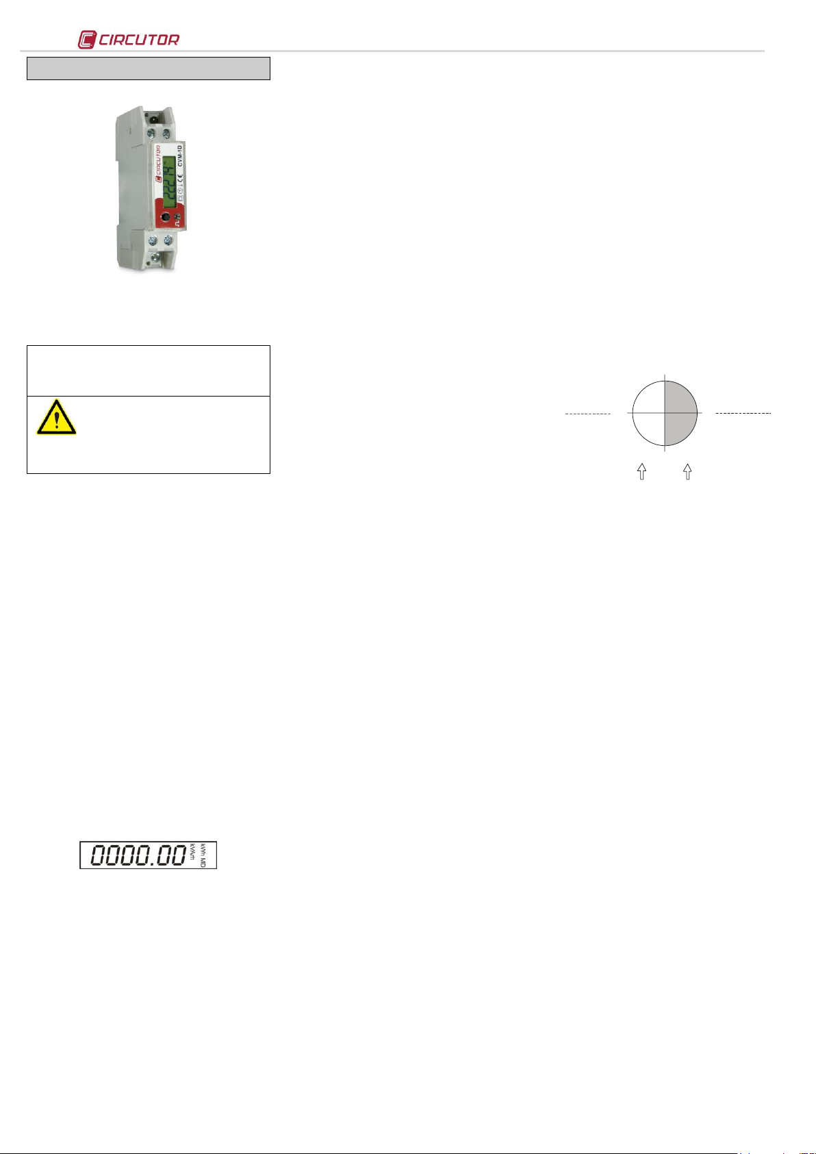
0º
90º
180º
-90º
Consumed
Power
Generated
Power
Single Phase
KW +
Kvar +
P.F +
Single Phase
KW +
KvarC P.F -
Single Phase
KW Kvar P.F -
Single Phase
KW KvarL+
P.F +
Three Phase
KW III +
KVA III +
KvarL III +
Three Phase
KW III +
KVA III +
KvarC III +
Three Phase
KW III KVA III KvarC III-
Three Phase
KW III KVA III KvarL III -
Capacitive
Inductive
Inductive
Capacitive
The CVM-1D is an instrument that measures, calculates and
displays the main electrical parameters in industrial and
domestic single-phase power networks. The measurement is
an RMS value made by direct measurement of the current and
voltage. The measured and calculated parameters are shown
in the table of variables.
1.- Button
The CVM-1D analyzer's front panel has a six digit LCD display
as well as a button function that enables the user to navigate
through the different display screens of the primary electrical
variables.
This button is used for two types of navigation, depending on
how it is pressed:
SHORT PRESS: This type of press occurs when the user
maintains the function button pressed for less than two
seconds. With a short press, the device moves through the
different navigation screens, displaying all the electrical
parameters on the display (refer to section 2.- Display). In
numerical setting, the short press allows a cyclical increase
the value of the digit.
LONG PRESS: This type of press occurs when the user maintains
the function button pressed for longer than two seconds. With
a long press, the device intermittently displays the maximum
and minimum values of the variable that is displayed at that
moment. With a long press on the partial power values, the
unit resets these values. In numerical settings, long press
allows the left lateral selection and posterior digit validation. If
the selected value is not correct, the digits will blink indicating
the user to enter a correct value (refer to section 5.- Setup,
allowed values).
2.- Display
The unit's front panel incorporates an LCD display with six
digits. By repeatedly pressing the function button located on
the front panel, the unit displays the different measured
electrical parameters and the symbol corresponding to the
displayed variable.
3.- Measurement
The Power analyzer CVM-1D is a measuring unit with four
quadrants, which is valid for conventional power consumption
systems and systems where a certain type of generation
source exists.
For this, the unit is able to display the primary electrical
variables with their sign (kW and kVA ), displaying the direction
of the current.
3.1.- Electrical Variables
The electrical variables are displayed on the unit by a rotating
display screen system. This enables the user to quickly
display all the electrical variables by repeatedly pressing the
function button.
Upon start-up and after the unit is connected to an auxiliary
power supply, the unit displays the firmware versionfollowed
by the following electrical variables:
3.1.1.- Phase – neutral voltage
Voltage between the phase and the neutral with a maximum
resolution of 1 decimal points (235.1 V). By pressing and
holding the voltage value, the unit displays the maximum
value by fast flashing and the minimum recorded value by
slow flashing.
3.1.2.- Current
Briefly pressing the function button, the unit displays the
Current with a maximum resolution of 2 decimal points (15.24
A).
By pressing and holding the voltage value, the unit displays
the maximum value flashing quickly and the minimum
recorded value flashing slowly.
3.1.3.- Active Power
By briefly pressing the function button, the unit displays the
Active Power with a maximum resolution of 2 decimal points
(3.24 kW). If the measurement is taken at the output of a power
generator load, the parameter is displayed with a negative
sign.
By pressing and holding the active power value, The unit
displays the maximum value flashing quickly and the minimum
recorded value flashing slowly.
3.1.10.- Partial Active Energy
By briefly pressing of the function button, the unit displays par
before the Partial Active Energy Consumption with a
maximum resolution of 1 decimal point and a background
scale of 99999.9 kW h. By pressing and holding the partial active
energy value, the unit resets both partial meters (partial active
energy consumption and partial reactive energy consumption).
3.1.11.- Partial Reactive Energy
By briefly pressing of the function button, the unit displays the
Partial Reactive Energy with a maximum resolution of 1
decimal point, with a background scale of 99999. 9 kVAr·h. The
unit displays the work quadrant with its sign (see diagram
Sign convention). By pressing and holding the partial active
energy value, the unit resets both partial meters (partial active
energy consumption and partial reactive energy consumption).
3.1.12.- Generated Active and Reactive Energy
By activating the measurement in four quadrants via the
setup, the analyzer displays gen before the Generated Active
and Reactive Energy as well as a second block of partial
meters.
By pressing and holding the partial meters display, the unit
resets both partial meters (generated partial active energy
and generated partial reactive energy).
4.- Sign convention
3.1.4.- Reactive Power
By briefly pressing the function button, the unit displays the
Reactive Power with a maximum resolution of 2 decimal
points (2.12 kvar).
The unit displays the work quadrant with its sign; if the value
is positive, it displays the Inductive Reactive Power (kvarL); if
the value is negative, it displays the Capacitive Reactive
Power (kvarC).
By pressing and holding the reactive power value, The unit
displays the maximum value flashing quickly and the minimum
recorded value flashing slowly.
3.1.5.- Apparent Power
By briefly pressing the function button, the unit displays the
Apparent Power with a maximum resolution of 2 decimal
points (5.10 kVA). If the measurement is taken at the output of a
power generator load, the parameter is displayed with a
negative sign.
By pressing and holding the apparent power value, the unit
displays the maximum value flashing quickly and the minimum
recorded value flashing slowly.
3.1.6.- Maximum demand
By briefly pressing of the function button, the unit displays the
Maximum Demand. The maximum demand is calculated using
the sliding window method for a time set by the user via the
configuration setup.
The maximum demand can be calculated with respect to two
selectable variables (A - kW). The unit is set as follows by
default:
a) md co de: Active Power (KW)
b) Period : 15 minutes
By pressing and holding the maximum demand value, the
unit displays the maximum value flashing quickly and the
minimum recorded value flashing slowly.
3.1.7.- Power Factor
By briefly pressing the function button, the unit displays the
Power Factor with a maximum resolution of 2 decimal points
(-0.99). The unit displays the work quadrant with its sign (see
diagram Sign convention).
By pressing and holding the power factor value, the unit
displays the maximum value flashing quickly and the minimum
recorded value flashing slowly.
3.1.8.- Active Energy
By briefly pressing of the function button, the unit displays
cons before the Active Energy Consumption with a maximum
resolution of 1 decimal point, with a background scale of
99999.9 kWh.
3.1.9.- Reactive Energy
By briefly pressing the function button, the unit displays the
Reactive Energy Consumption with a maximum resolution of 1
decimal point, with a background scale of 99999.9 Kvarh. The
unit displays the work quadrant with its sign (see diagram
Sign convention).
5.- Setup
To enter the configuration setup, display an energy variable
(any), and make a long press to the function button, to display
on the screen SETUP.
By pressing and holding, the unit displays the different
configuration sections, and by pressing briefly, you can
change their values.
a) nPEr : peripheral number 001...254 - Default (1)*
b) bAud: rate 2400-480 0-9600-19200 - Default (19.200)*
c) quad: 2 quadrants / 4 quadrants
d) max imum demand configuration
- MD VAR: 3 (kW- active power) / 2 (A - current)
- MD per: 1...60 minutes
e) F.O UT: PULSE (pulse function) / ALARM (alarm function)*
PULS – FUNCtion energy impul se:
- P VAR: 10, 11, 12, 13 (consumed)) 18., 19, 20 ,21 (generated)
- P TIME: 40...200 ms. (pulse duration)
ALARM – alarm function:
- A VAR: 1...9 (instant variable)
- A MAX: maximum value
- A MIN: minimum value
- ADLAY: delay connection and disconnection (0...60 sec)
In the alarm function, the digital output is maintained open
between the maximum and minimum value. In the case of
programming an inverse logic (normally closed), invert the
maximum and minimum values in the Setup menu.
The p VAR and a var CODES are specified in the Modbus/RTU
memory Map table, in the Var column. If you do not wish to
programme a variable, select 00.
To validate the modified data in setup, ensure you can view
all of the display screens by pressing and holding, until
completing all of the configuration options. At the end of the
process, the unit validates and saves the changes that have
been carried out.
If the configuration process is not completely finished and
after not having pressed the function key for 10 seconds, the
unit returns to the display screen, and exits the setup menu
without saving the data that has been modified by the user.
*Options a) and b), are listed in model RS485, since it
expressly references the device's communication parameters.
Option e) is fixed to “pulse-active energy consumed” in the
MID certified device.The rest of the options are listed in all the
CVM-1D range references.
M98236001-03-14A
Page 2
CVM-1D
Parameters
Symbol
Var
Instantaneous
Maximum
Minimum
Units
Parameters
Var
Symbol
Instantaneous
Maximum
Minimum
Units
Voltage V 1
0000-0001
0032-0033
0044-0045
V x10
Partial Active Energy
14
kW·h
001A-001B
-
-
kW·h x100
Current A 2
0002-0003
0034-0035
0046-0047
A x100
Partial Inductive Reactive Energy
15
kvarL·h
001C-001D
-
-
kvarL·h x100
Active Power
kW 3 0004-0005
0036-0037
0048-0049
± kW x100
Partial Capacitive Reactive Energy
16
kvarC·h
001E-001F
-
-
kvarC·h x100
Reactive Power (L/C)
kvar 4 0006-0007
0038-0039
004A-004B
± kvar x100
Partial Reactive Energy (L/C)
17
kvar·h
0020-0021
-
-
kvar··h x100
Inductive Reactive Power
kvarL 5 0008-0009
003A-003B
004C-004D
± kvarL x100
FOUR QUADRANTS MEASUREMENT
Capacitive Inductive Power
kvarC 6 000A-000B
003C-003D
004E-004F
± kvarC x100
Generated Active Energy
18
kW·h
0022-0023
-
-
kW·h x100
Apparent power
kVA 7 000C-000D
003E-003F
0050-0051
± kVA x100
Generated Inductive Reactive Energy
19
kvarL·h
0024-0025
-
-
kvarL·h x100
Power Factor
PF 8 000E-000F
0040-0041
0052-0053
PF
Generated Capacitive Reactive Energy
20
kvarC·h
0026-0027
-
-
kvarC·h x100
Maximum Demand
kW / A 9 0010-0011
0042-0043
0054-0055
kW / A x100
Generated Total Reactive Energy (L/C)
21
kvar·h
0028-0029
-
-
kvar·h x100
Active energy
kW·h
10
0012-0013
-
-
kW·h x100
Partial Generated Active Energy
22
kW·h
002A-002B
-
-
kW·h x100
Inductive Reactive Energy
kvarL·h
11
0014-0015
-
-
kvarL·h x100
Partial Generated Inductive Reactive Energy
23
kvarL·h
002C-002D
-
-
kvarL·h x100
Capacitive Reactive Energy
kvarC·h
12
0016-0017
-
-
kvarC·h x100
Generated Capacitive Reactive Energy
24
kvarC·h
002E-002F
-
-
kvarC·h x100
Reactive Energy (L/C)
kvar·h
13
0018-0019
-
-
kvar·h x100
Partial Generated Total Reactive Energy (L/C)
25
kvar·h
0030-0031
-
-
kvar·h x100
Supply specifications :
- Single-phase :
- Frequency:
- Maximum consumption :
88…276 V
c.a
50 / 60 Hz
2 VA
Metering circuit:
- Nominal voltage / Tolerance:
- Nominal voltage / MID Tolerance:
- Frequency :
- MID frequency:
- Nominal current/minimum/maximum:
- Start current (Ist):
- Reference current (Iref):
- Transition current (Itr):
110…230 V
c.a
/ ±20 %
230 V
c.a
/ ±20 %
50 / 60Hz
50Hz
5 A / 250 mA / 32 A
20 mA
5 A
500 mA
Mechanical specifications:
- Case material :
- Protection :
Fitted unit (front panel) :
Fitted MID unit (front panel) :
Non-fitted unit (front panel):
- Maximum Dimensions (mm) :
- Weight :
Selft-extinguish UL94-V0 plastic
IP31
IP51
IP20
85.5 x 64.2 x 18 mm (1 DIN rail module)
150 g
Output transistor specifications
- Typo: opto-isolated transistor (open
collector)
- Maximum operating voltage:
- Maximum operating current:
- Maximum frequency:
- Pulse width:
NPN
42 V
c.c.
50 mA
1000 imp / kW·h
40…200ms (configurable)
Environmental specifications:
- Working temperature:
- Storage temperature:
- Humidity:
- Maximum altitude:
-5...+45 ºC
-25...+70 ºC
5…95% non condensing
2000m
Safety:
CATIII-300 EN61010-1:2010 EN61010-2-030:2011. Double insulation. Pollution degree II.
Means for disconnecting the power from the device must be provided in the installation.
Wire conductor are must be choosen depending on current to flow acroos the device.
Minimum recommended wire is 1mm2
Standards :
EN 50470-1, EN50470-3, EN62053-21, EN62053-23, EN61010-1:2010,
EN 61000-6-4, EN 55022
Energy meter: Class B EN50470-3 Active Energy, Class 2 EN62053-23 Reactive
Energy.
Accuracy:
- Voltage :
- Current :
- Power / Energy :
Sensors :
- Voltage :
- Current :
Power factor :
Measurement range:
0.5 % ± 1 digit
0.5 % ± 1 digit
1 % ± 1 digit
Direct. Impedance 1M
Direct (shunt <0,5 m)
0.5...1
0.5...120% FS
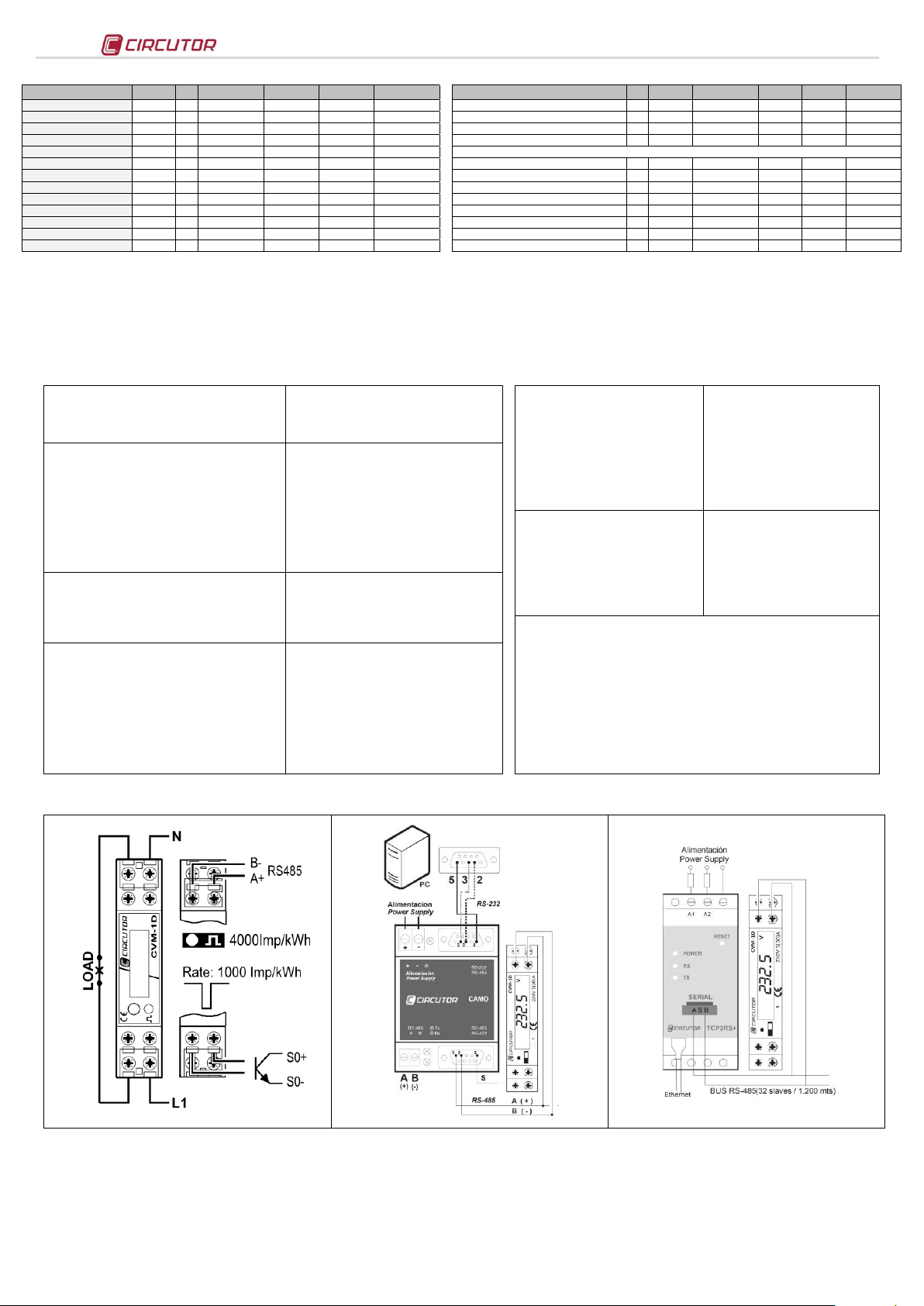
Single-phase connection system
RS-485 communications
6.- Modbus/RTU memory map
7.- CVM-1D communication
One or several -CVM-1D analyzers can be connected to a controller or PLC. Using this system you can operate each of the analyzers as usual as well as centralize the data in a single
location. CVM-1D incorporates an RS-485 type communications output. If more than one analyzer is connected to an RS-485 serial bus, each of them must be assigned a peripheral
number or address so that the communications master can send the queries regarding the different measured or calculated records to those addresses.the RS-485 connection is carried out
via the shielded twisted pair communication cable, with a minimum of two wires and with a maximum distance between the communications master and the last unit of 1,200 metros. The
device uses an RS-485 communications line that can support a maximum of 32 units in series per bus.
The CVM-1D type power analyzer communicates via a Modbus/RTU© protocol (Question / answer polling).
8.- Technical specifications
9.- Connections
10.- Technical Service
If you have any doubts about the operation of the unit or suspect any malfunction, contact our service staff at CIRCUTOR, SA
CIRCUTOR, SA - Technical Assistance Service
Vial Sant Jordi, s/n
08232 – Viladecavalls (Barcelona),Spain
Tel: 902 449 459SPAIN
Tel: (+34) 93 745 29 00 (outside of Spain)
email: sat@circutor.es
M98236001-03-14A
 Loading...