

Page 1

MULTIMETER CURRENT CLAMP
CPM
(Code: M80430)
INSTRUCTION MANUAL
( M98111201-03-10A )
CIRCUTOR S.A.
Page 2

--------- MULTIMETER CURRENT CLAMP
-
CPM
-------- PG No. 1
CPM ANALYZER INDEX page no.
SAFETY NOTES
Before using the equipment please read the user manual, paying special attention to
the SAFETY REQUIREMENTS section.
The symbol on the equipment means "CONSULT THE INSTRUCTION
MANUAL". It can also appear as a symbol of warning or caution in this manual.
WARNING and CAUTION statements can appear throughout this manual to avoid
hazard to persons or damage to equipment or other property.
1.- OVERVIEW
1.1.- Description
The CPM Current clamp provides functions for the measurement of voltage,
current, resistance, continuity sound alarm, diode test, as well as frequency
measurement.
Three push buttons allow for the selection of functions such as measurement
hold (HOLD), maximum value (MAX) and reset for current measurement DC (DCA
ZERO).
Page 3

--------- MULTIMETER CURRENT CLAMP
-
The analyzer is powered by a 9 V battery. Its design and its double insulation
makes the CPM a robust and secure instrument.
CPM
-------- PG No. 2
Page 4
--------- MULTIMETER CURRENT CLAMP
1.2.- Specifications
CPM
-------- PG No. 3
-
Display
3 ½ digit LCD display with a maximum
reading of 1999.
Display functions
Hold
MAX
Polarity
Measurement value hold.
Maximum measurement value hold.
Automatic, positive by default and indication
of negative polarity (-).
Overrange
Zero
Low battery indication
(OL) or (-OL) appears on the display.
Automatic
The“ “indicator appears when the battery
voltage is below the level of operation.
Reading rate
2.5 measurements a second, nominal.
Page 5

--------- MULTIMETER CURRENT CLAMP
-
CPM
-------- PG No. 4
Power Supply
Battery life
9 V, IEC 6F22 battery.
Typically 200 hours for a zinc-carbon
battery
Environmental conditions
Operating temperature
Storage temperature
0 °C to 40 °C (H.R. 0-70%)
20 °C to 60 °C, (H.R. 0-80%) with the
battery removed
Dimensions
Weight
Accessories
250 (W) x 100 (H) x 46 mm. (D.)
380 g, including the battery.
A pair of test probes
Transport case
Reference conditions
Referring to environmental conditions:
23 °C ± 5 °C, HR < 75%.
Page 6

--------- MULTIMETER CURRENT CLAMP
-
CPM
-------- PG No. 5
DC Voltage
Range
Accuracy
Input impedance
Overload protection
AC Voltage (50-500 Hz)
Ranges
Accuracy
Input impedance
Overload protection
Resistance
Ranges
Accuracy
Open circuit voltage
Overload protection
Frequency (Autoranging)
Ranges
Accuracy
Sensitivity
Overload protection
600 V
± (0.5% read. + 1 digit)
10 MΩ
600 V DC or AC rms
200 V, 600 V
± (1.2% read. + 4 digits)
10 MΩ
600 V DC or AC rms
2 kΩ, 200 kΩ
± (1.2% read. + 1 digit)
0.3 V DC
600 V DC or AC rms
2 kHz, 20 kHz
± 0.1% read. + 3 digits.
80 V rms minimum
600 V DC or AC rms
Page 7

--------- MULTIMETER CURRENT CLAMP
-
CPM
-------- PG No. 6
Continuity
Sound alarm
Overload protection
Diode test
Test current
Accuracy
Open circuit tension
Sound alarm
Overload protection
DC Current (Place the conductor in
the centre of the clamp).
Ranges
Resolution
Accuracy
Overload protection
AC Current (40 Hz to 500 Hz)
(Place the conductor in the centre of
the clamp.)
Ranges
Resolution
Accuracy
Overload protection
Less than 30Ω in the range of 2kΩ.
600 V DC or AC rms
1.0 mA ± 0.6 mA
± (6.0% read. + 3 digits)
3.0 V DC typically
< 30 mV
600 V DC or AC rms
200 A, 700 A
100 mA
± (1.5% read. + 5 digits)
700 A DC Max. during 1 minute.
200 A, 700 A
100 mA
±(1.5% read. + 5 digits) from 50 to 60
Hz
±(3.5% read. + 5 digits) from 40 to 500
Hz
Page 8

--------- MULTIMETER CURRENT CLAMP
-
700 A AC Max. during 1 minute.
CPM
-------- PG No. 7
Page 9

--------- MULTIMETER CURRENT CLAMP
-
CPM
-------- PG No. 8
2.- SAFETY REQUIREMENTS
2.1.- General
This equipment can be used in environments of Pollution Degree 2.
Overvoltage Category: See sections 2.2 and 2.3.
In order to ensure safety only the following specified types of the accessories
must be used:
Test probes:
Always keep the specified ranges in mind for both power supply and
measurement.
Obey the maximum environmental conditions specified for the apparatus at
all times.
Remember that voltages higher than 60 V DC or 30 V AC rms are potentially
dangerous.
The operator is only authorized to intervene for: Battery replacement
Specific instructions for these interventions are defined in the Maintenance
section.
Any other change made to the equipment must be done exclusively by
specialized personnel.
Strictly follow the cleaning recommendations that are described in the
Maintenance section.
Page 10
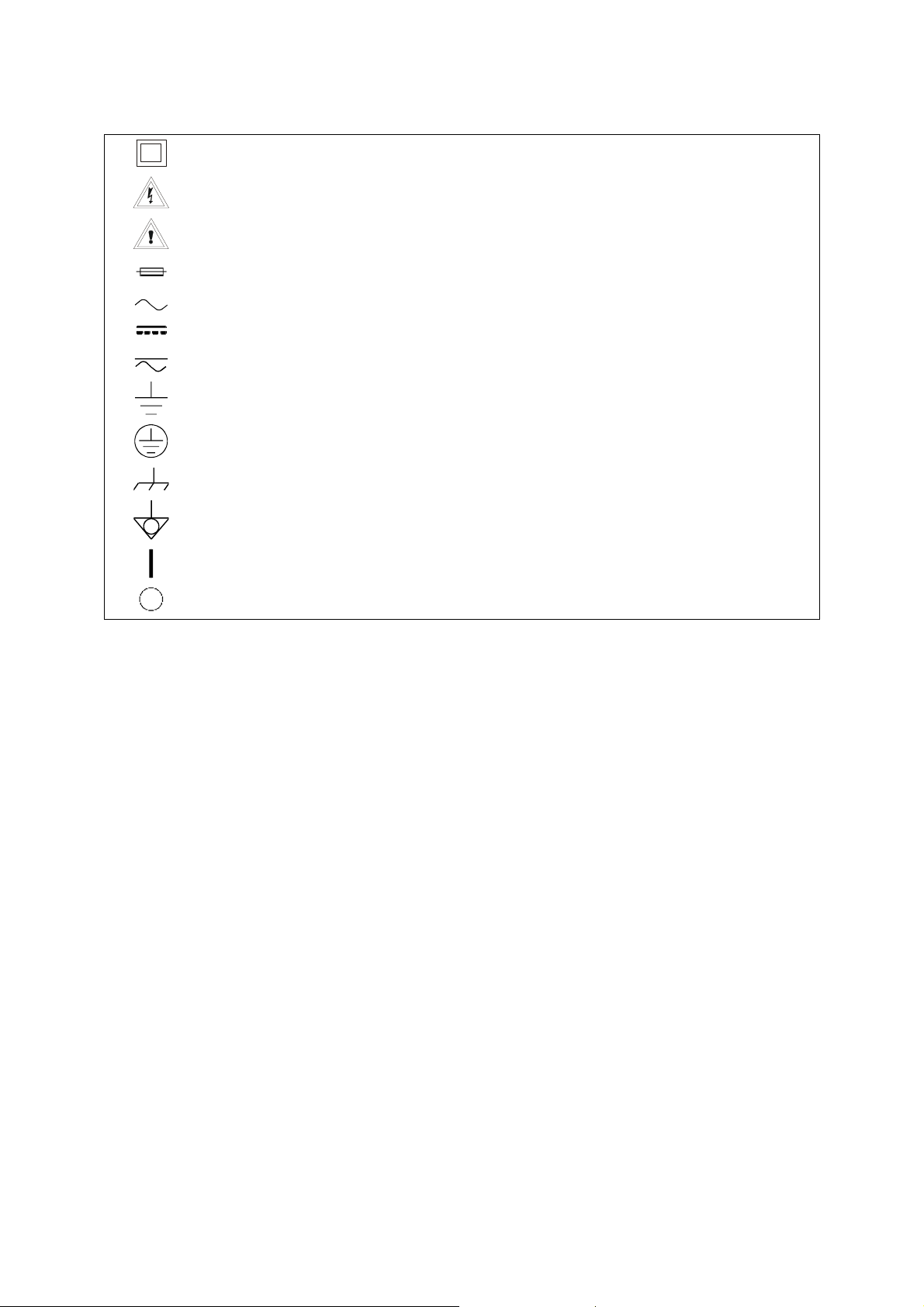
Symbols:
--------- MULTIMETER CURRENT CLAMP
-
CPM
-------- PG No. 9
The analyzer is protected by double or reinforced insulation.
Caution! Risk of electric shock.
Caution! See this manual before using the analyzer.
Fuse
Alternating current
Direct current
Alternate and direct
Earth terminal
Protection terminal
Shell terminal
Equipotentiality
Start
Stop
Page 11

--------- MULTIMETER CURRENT CLAMP
-
CPM
-------- PG No. 10
2.2.- Special precautions
This equipment can be used for Overvoltage Category II installations.
The clamp can be used exclusively for the measurement of current for
installations of up to 600 V with Overvoltage Category IV.
When using the test probes fingers must be kept behind the protection
outcrops.
Maintain the test probes in good condition.
Note the correspondence between the connection of the probes and
the measurement to be taken.
2.3.- Descriptive examples of overvoltage categories
Cat I Low voltage installations isolated from the mains.
Cat II Portable domestic installations.
Cat III Fixed domestic installations.
Cat IV Industrial installations.
Page 12

--------- MULTIMETER CURRENT CLAMP
-
3.- INSTRUCTIONS FOR USE
3.1.- Description of controls and elements
B
CPM
A
-------- PG No. 11
Page 13

--------- MULTIMETER CURRENT CLAMP
-
CPM
-------- PG No. 12
[1] Rotary function switch
Analyzer off
DC voltage measurement, range 600 V
DC current measurement, range 700 A
DC current measurement, range 200 A
Resistance measurement, range 200 kΩ
Continuity test and resistance measurement, range 2 kΩ
Diode test
Hz Frequency measurement
AC current measurement, range 200 A
AC current measurement, range 700 A
AC voltage measurement, range 200 V
AC voltage measurement, range 600 V
[2] DCA ZERO
In DC current measurement mode, press this key to select/deselect the
relative measurement mode, the ZERO indicator will appear on the display
and the measurement will change to zero, while the reading is stored as a
reference value.
Page 14

--------- MULTIMETER CURRENT CLAMP
-
CPM
-------- PG No. 13
[3] V input terminal for AC/DC voltage measurement
[4] COM common input terminal for test probes for all measurements.
[5] Input terminal for resistance measurements, frequency and diode
tests.
[6] DISPLAY
Display of measured values and operating mode
[7] MAX maximum value hold key
This key selects/deselects the MAX measuring mode. In this measuring mode
the absolute maximum value is held. When this function is activated "MAX"
appears on the upper part of the display. This function does not operate in
frequencymeter mode.
[8] Measurement hold key.
This key allows to select/deselect the "HOLD" function (measurement hold).
When this function is activated a "H" appears on the upper line of the display.
The HOLD function is deactivated on function or range change.
Page 15

--------- MULTIMETER CURRENT CLAMP
-
CPM
-------- PG No. 14
3.2.- Use
ATTENTION
When the value to be measured is unknown always place the rotary switch to the
highest range and reduce it progressively in function of the value in question.
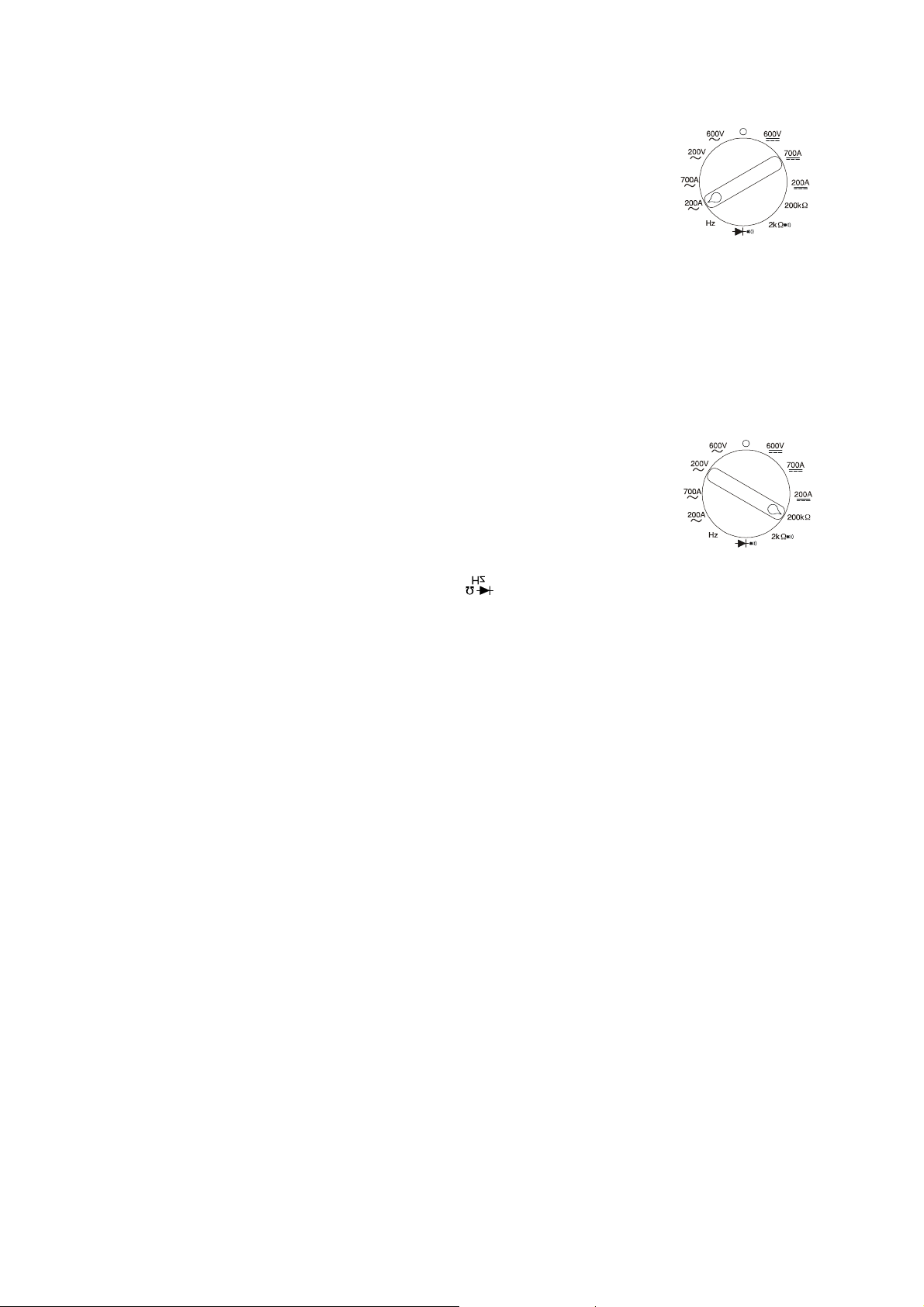
3.2.1.- Voltage measurement
1. Connect the red test probe to the "V" terminal [3] and the
black test probe to "COM" terminal [4].
2. Set the rotary switch [1] to the appropriate "V" position
(AC or DC and suitable range). If the size of the voltage
to be measured is unknown, set the switch to the highest range and then
start reducing it until the highest accuracy is obtained.
3. Connect the test probes to the points to be measured and read the display.
For DC voltages, the "-" sign indicates a negative polarity.
Page 16
--------- MULTIMETER CURRENT CLAMP
-
CPM
-------- PG No. 15
3.2.2.- Current measurement
1. Set the rotary switch [1] to the desired higher range 700 A
(AC or DC). In DC current measurement mode use the
DCA ZERO button [2] to delete the offset due to the
residual magnetism of the clamp.
2. Press the trigger to open the clamp and encompass one conductor only.
Read the current value directly from the display [6]. It is recommended to
place the conductor in the centre of the clamp for maximum accuracy.
3. When the reading is less than 200 counts, set the switch [1] to the
measurement range below the current position. For maximum accuracy,
select the lowest range margin in which the measurement can be taken (i.e.
the overrange indicator does not appear).
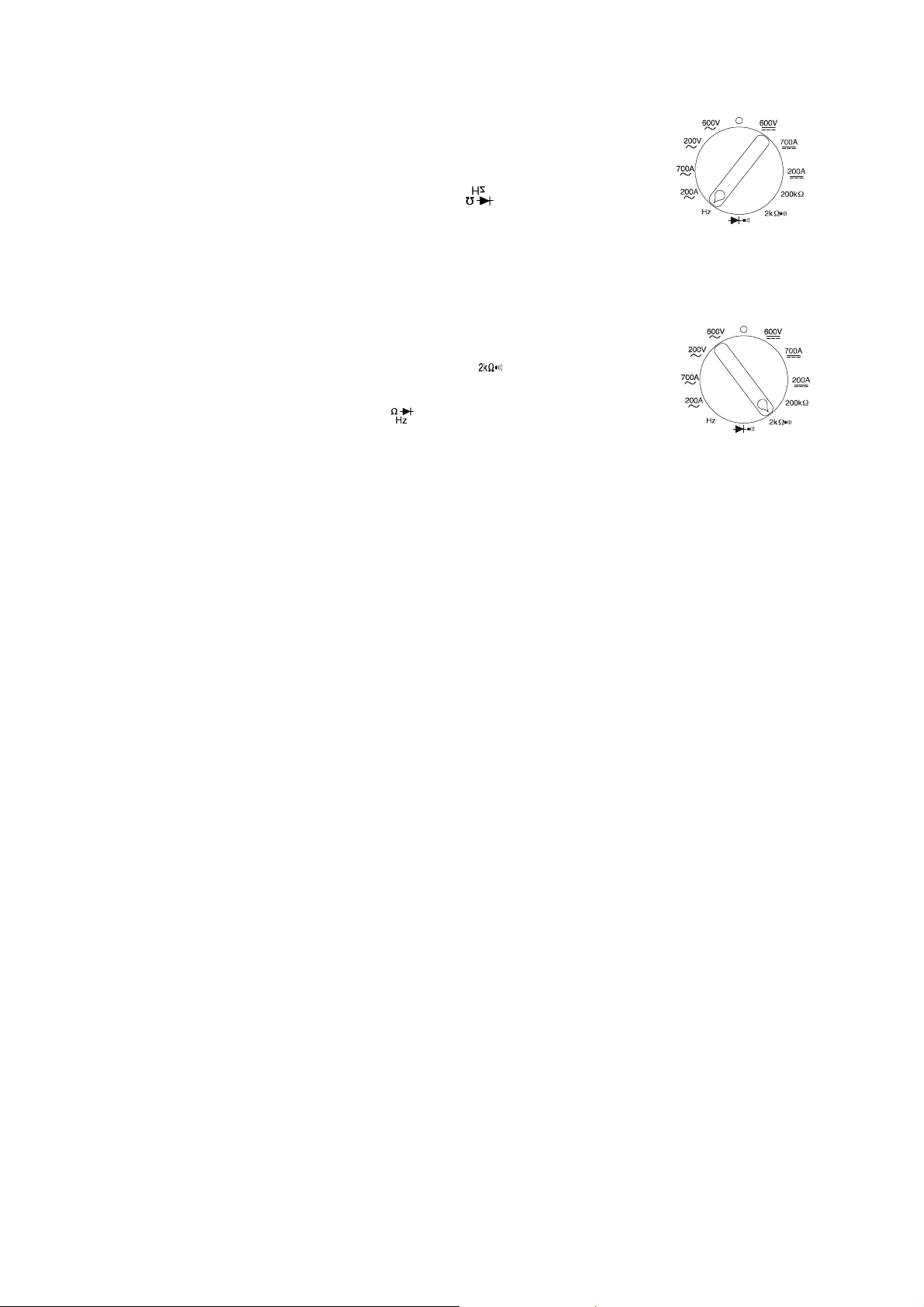
3.2.3.- Resistance measurement
1. Set the rotary switch [1] to the desired resistance
measurement range.
2. Disconnect the power supply to the circuit being
measured.
3. Connect the red test probe to the terminal [5] and the black test probe
to the COM terminal [4].
4. Connect the load using the test probes. On the display [6] the value of the
tested resistance will appear in ohms.
Page 17
--------- MULTIMETER CURRENT CLAMP
-
CPM
-------- PG No. 16
3.2.4.- Frequency measurement
1. Set the rotary switch [1] to the Hz position.
2. Connect the red test probe to the terminal [5] and the
black test probe to the COM terminal [4].
3. Connect the test probes in parallel with the points to be measured and read
the frequency value on the display [6].
3.2.5.- Continuity sound alarm
1. Set the rotary switch [1] to position“ “ .
2. Connect the black test probe to the COM terminal [4] and
the red test probe to the terminal [5].
3. Connect the test probes to the points to be verified.
4. If the resistance value is less than 30 Ω the built in alarm will sound.
Page 18

--------- MULTIMETER CURRENT CLAMP
-
CPM
-------- PG No. 17
3.2.6.- Diode test
1. Connect the black test probe to the COM terminal [4]
and the red test probe to the terminal [5].
2. Set the rotary switch [1] to the position “ “ .
3. Disconnect the power supply to the circuit being tested.
4. Connect the black test probe to the negative (-) side of the diode and the
red test probe to the positive (+) side. Normally the direct voltage of a good
silicon diode is of 0.6 V.
5. On inverting the test probes, if the diode is good “OL” will appear on the
display [1] and if it is faulty, 000 or another value will appear.
6. If the diode is open, the “OL” indicator will appear for each direction.
7. If the diode of a circuit is measured and a low measurement is obtained for
each measurement direction, then the junction must be in parallel and with
a resistance of less than 1 kΩ. In this case the diode must be disconnected
from the circuit in order to perform an exact measurement.
Page 19

--------- MULTIMETER CURRENT CLAMP
-
CPM
-------- PG No. 18
4.- MAINTENANCE
Attention : Disconnect the test probes before changing the battery or performing
any maintenance service.
4.1.- Battery replacement
When the symbol “ ” appears on the lower left corner of the LCD indicator,
the batteries must be replaced:
1. Loosen the screws with a suitable screwdriver and remove the back cover.
2. Replace the battery with an IEC 6F22 9 V.
3. Close the back cover.
4.2.- Cleaning and storage
Caution : To clean the case, make sure that the equipment is disconnected.
Page 20

--------- MULTIMETER CURRENT CLAMP
-
CPM
-------- PG No. 19
Caution : Do not use aromatic hydrocarbons or chlorinated solvents for
cleaning. These products can attack the materials used to make
the case.
Clean the case periodically with a soft cloth moistened with water and
detergent. Do not use abrasives or solvents. Dry thoroughly before reusing the
equipment.
4.3.- TECHNICAL SERVICE
In the case of any query regarding the operation or fault of the equipment
contact the CIRCUTOR S.A technical service.
CIRCUTOR S.A. - Post-sales service
Vial Sant Jordi, s/n
08232 – Viladecavalls
Tel. 902449459 (Spain)
Tel. – (+34) 93 745 29 00 (rest of the world)
Fax – (+34)93 745 29 14
E-mail: sat@circutor.es
 Loading...