

Page 1
Protocol transducer
CMBUS-8 CMBUS-24
INSTRUCTION MANUAL
(M98252701-03-14A)
Page 2

CMBUS
2
Instruction Manual
Page 3
CMBUS
SAFETY PRECAUTIONS
Follow the warnings described in this manual with the symbols shown below.
DANGER
Warns of a risk, which could result in personal injury or material damage.
ATTENTION
Indicates that special attention should be paid to a speci c point.
If you must handle the unit for its installation, start-up or maintenance, the following
should be taken into consideration:
Incorrect handling or installation of the unit may result in injury to personnel as well as damage
to the unit. In particular, handling with voltages applied may result in electric shock, which may
cause death or serious injury to personnel. Defective installation or maintenance may also
lead to the risk of re.
Read the manual carefully prior to connecting the unit. Follow all installation and maintenance
instructions throughout the unit’s working life. Pay special attention to the installation standards of the National Electrical Code.
Refer to the instruction manual before using the unit
In this manual, if the instructions marked with this symbol are not respected or carried out correctly, it can
result in injury or damage to the unit and /or installations.
CIRCUTOR, SA reserves the right to modify features or the product manual without prior noti cation.
DISCLAIMER
CIRCUTOR, SA reserves the right to make modi cations to the device or the unit speci ca-
tions set out in this instruction manual without prior notice.
CIRCUTOR, SA on its web site, supplies its customers with the latest versions of the device
speci cations and the most updated manuals.
www.circutor.com
Instruction Manual
3
Page 4

CMBUS
CONTENTS
SAFETY PRECAUTIONS ���������������������������������������������������������������������������������������������������������������������������������������3
DISCLAIMER ����������������������������������������������������������������������������������������������������������������������������������������������������������3
CONTENTS ������������������������������������������������������������������������������������������������������������������������������������������������������������� 4
REVISION LOG �������������������������������������������������������������������������������������������������������������������������������������������������������5
1�- VERIFICATION UPON RECEPTION ����������������������������������������������������������������������������������������������������������������� 6
2�- PRODUCT DESCRIPTION �������������������������������������������������������������������������������������������������������������������������������� 6
3�- UNIT INSTALLATION ���������������������������������������������������������������������������������������������������������������������������������������� 7
3�1�- PRELIMINARY RECOMMENDATIONS �����������������������������������������������������������������������������������������������������7
3�2�- INSTALLATION ������������������������������������������������������������������������������������������������������������������������������������������7
3�3�- UNIT TERMINALS �������������������������������������������������������������������������������������������������������������������������������������� 9
3�4�- CONNECTION DIAGRAM ������������������������������������������������������������������������������������������������������������������������ 10
4�- START-UP �������������������������������������������������������������������������������������������������������������������������������������������������������� 11
5�- OPERATION ����������������������������������������������������������������������������������������������������������������������������������������������������12
5�1�- LED INDICATORS ������������������������������������������������������������������������������������������������������������������������������������ 12
5�2�- PROGRAMMING �������������������������������������������������������������������������������������������������������������������������������������� 12
5�2�1� INSTALLATION OF THE CMBUS SOFTWARE �������������������������������������������������������������������������������� 12
5�2�2�- ADDING M-BUS UNITS FROM THE DATABASE ���������������������������������������������������������������������������� 15
5�2�3� ADDING M-BUS UNITS THROUGH AUTO-DETECTION�����������������������������������������������������������������16
5�2�4� CMBUS START-UP ���������������������������������������������������������������������������������������������������������������������������18
6�- TECHNICAL FEATURES ��������������������������������������������������������������������������������������������������������������������������������20
7�- MAINTENANCE AND TECHNICAL SERVICE ������������������������������������������������������������������������������������������������22
8�- WARRANTY �����������������������������������������������������������������������������������������������������������������������������������������������������22
9�- CE CERTIFICATE �������������������������������������������������������������������������������������������������������������������������������������������� 23
4
Instruction Manual
Page 5

CMBUS
REVISION LOG
Table 1: Revision log�
Date Revision Description
09/14 M98252701-03-14A Initial Version
Note: The images of the units are for illustrative purposes only and may differ from the original
unit.
Instruction Manual
5
Page 6
1�- VERIFICATION UPON RECEPTION
Check the following points when you receive the unit:
a) The unit meets the specications described in your order.
b) The unit has not suffered any damage during transport.
c) Perform an external visual inspection of the unit prior to switching it on.
d) Check that it has been delivered with the following:
- An installation guide.
If any problem is noticed upon reception, immediately contact the transport
company and/or CIRCUTOR's after-sales service.
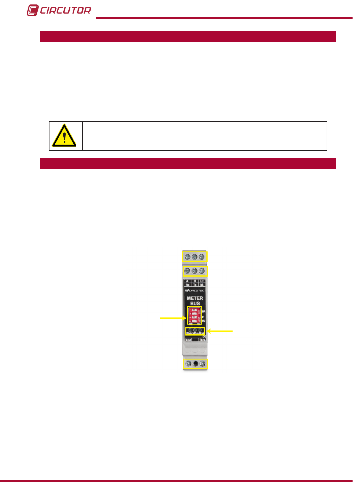
2�- PRODUCT DESCRIPTION
CMBUS
CMBUS protocol transducers enable devices with RS-485 Modbus Master communications to
communicate with different M-BUS slave units.
There are two unit models:
The CMBUS-8 model can communicate with 8 slave units (100 parameters).
The CMBUS-24 model can communicate with 24 slave units (500 parameters).
Terminals
MiniDips
LEDs
Terminals
Figure 1: Description of the CMBUS
The unit features:
4 MiniDips for conguration,
3 LEDs that indicate the converter status and the M-BUS and Modbus trafc,
An RS-232 connection for the initial conguration of the unit.
M-BUS slave units are integrated into the transducer using programming software.
6
Instruction Manual
Page 7
CMBUS
3�- UNIT INSTALLATION
3.1.- PRELIMINARY RECOMMENDATIONS
In order to use the unit safely, it is critical that individuals who handle it follow
the safety measures set out in the standards of the country where it is being
used, use the personal protective equipment necessary, and pay attention to the
various warnings indicated in this instruction manual.
The CMBUS unit must be installed by authorised and qualied staff.
The power supply plug must be disconnected and measuring systems switched off before
handling, altering the connections or replacing the unit. It is dangerous to handle the unit while
it is powered.
Also, it is critical to keep the cables in perfect condition to avoid accidents, personal injury and
damage to installations.
The manufacturer of the unit is not responsible for any damages resulting from failure by the
user or installer to heed the warnings and/or recommendations set out in this manual, nor for
damages resulting from the use of products or accessories that did not come with the unit or
that were made by other manufacturers.
Disconnect the unit from the power supply (unit and measuring system power
supply) before maintaining, repairing or handling the unit's connections.
Please contact the after-sales service if you suspect that there is an operational
fault in the unit.
3.2.- INSTALLATION
Do not use the unit until it is fully installed.
The unit is installed on a 35 mm DIN rail (EN 50022).
To install the unit on a DIN rail (Figure 2) :
1�- Hook the rear clip of the unit to the top of the DIN rail.
2�- Pull the clip downwards.
3�- Push the unit into place on the DIN rail and release the clip.
Instruction Manual
7
Page 8
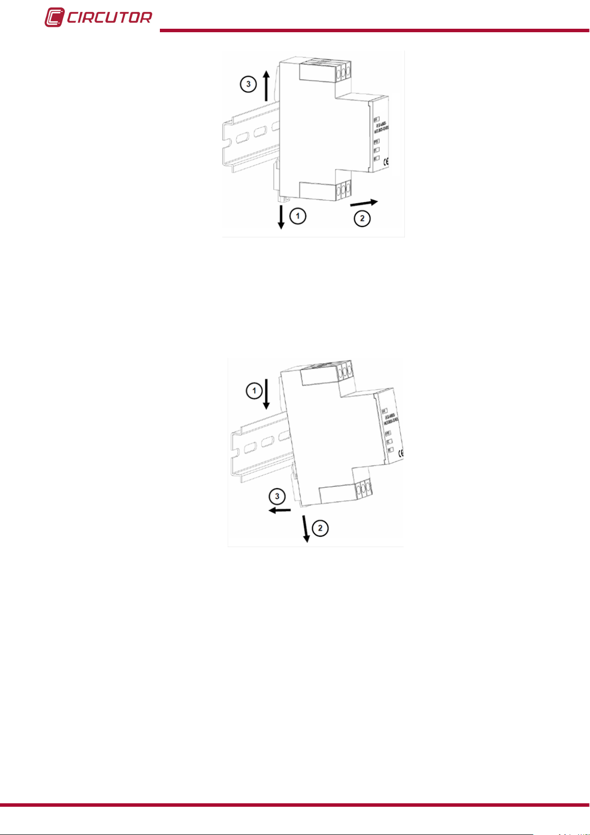
Figure 2: Installing the CMBUS on a DIN rail
To uninstall from the DIN rail (Figure 3):
1�- Pull the clip downwards.
2�- Pull the unit to release the bottom edge of the DIN rail.
3�- Pull the unit up to release the upper clip from the DIN rail.
CMBUS
Figure 3: Uninstalling the CMBUS from a DIN rail
8
Instruction Manual
Page 9

CMBUS
3.3.- UNIT TERMINALS
Table 2: List of unit terminals�
Terminal Description
A A (+) Modbus
B B (-) Modbus
L+ + 24 Vdc
M- GND
Rx RS-232, data reception
Tx RS-232, data transmission
MBUS+ + connection to M-BUS slaves
MBUS-
- connection to M-BUS slaves
A B L+
Terminals
Rx Tx M-
Terminals
Figure 4: Unit terminals
MBUS+ MBUS-
Instruction Manual
9
Page 10

3.4.- CONNECTION DIAGRAM
B(-)
MODBUS
CMBUS
A(+)
GND
Tx
L+
M-
AUX. Supply
24 V CC
RS-232
Rx
M-BUS n
MBUS-
MBUS+
MBUS+
M-BUS 1
MBUS-
MBUS-
Figure 5:Connection diagram
MBUS+
Note: RS-232 communications are used to congure the unit for the rst time via a PC.
10
Instruction Manual
Page 11

CMBUS
4�- START-UP
The initial conguration of the unit is complete using the 4 MiniDips found on the front panel
of the unit.
MiniDips
Figure 6: Location of the MiniDips in the CMBUS
Table 3: Initial conguration of the CMBUS.
Initial conguration
Speed MiniDip 1 MiniDip 2
9600 OFF OFF
19200 ON OFF
38400 OFF ON
57600 ON ON
Interface MiniDip 3
RS-232 (Programming) OFF
RS-485 (Modbus Master) ON
Peripheral no� MiniDip 4
As programmed OFF
By default (255) ON
Note: Restart the CMBUS by removing the power supply for a few seconds after making any
changes to the conguration using the MiniDips.
Instruction Manual
11
Page 12

CMBUS
5�- OPERATION
The M-BUS protocol (Meter-Bus) is a communications bus used to read information from gas,
water and energy meters.
M-BUS is a hierarchical protocol whose communication is controlled by a Master device with
a certain number of slave elements that respond to its queries.
The protocol is standardised according to the EN 13757-3 and EN 13757-2 standards.
The CMBUS transducer connects the M-BUS slave devices with a RS-485 master.
5.1.- LED INDICATORS
CMBUS has 3 LED indicators:
State: LED indicating the state of the converter, blinking light every 1 second.
MBUS: LED which blinks when there is data transmission in the M-BUS bus.
Host: LED which blinks when there is data transmission in the MODBUS bus.
5.2.- PROGRAMMING
The CMBUS has built-in Windows-compatible software with which you can:
Congure the communication parameters of the converter.
Congure the M-BUS slave units.
5�2�1� INSTALLATION OF THE CMBUS SOFTWARE
The CMBUS software must be run in a Windows environment (Windows XP or Windows 7)
with administrator rights.
Steps for CMBUS software installation:
1�- Download the programming software, CMBUS-SETUP.zip from the Circutor website
(www.circutor.es).
2�-Extract the content of the compressed le onto the computer.
3�-Run the CMBUS-SETUP.exe program in a Windows environment with administrator rights.
The program is compatible with 32-bit and 64-bit operating systems.
12
4�- Connect the CMBUS to the computer's RS-232 port, as shown in Figure 7�
Instruction Manual
Page 13

CMBUS
Tx
Rx
MODBUS
L+
M-
AUX. Supply
24V CC
Tx(3)
RS-232
Figure 7: CMBUS connection to the RS-232 port
Rx(2)
M-BUS
5�- Connect the CMBUS to the power supply.
6�- Put the MiniDip 3 on the front panel of the unit in the OFF position to enable the RS-232
conguration.
7�- Put the MiniDip 4 on the front panel of the unit in the ON position to congure the peripheral
number to 255.
8�- Select the serial port to which the CMBUS is connected on the main screen of the software
(Figure 8).
If in doubt, you can select more than one COM port so that the program auto-detects the
correct port.
Click on the button “FAST SCAN (only 255)”.
Figure 8: Selecting the COM port to which the CMBUS is connected
9�- Click on the button “Scan serial ports for devices”. The window status bar indicates the
progress of the detection process of the transducer. (Figure 9)
If nothing is detected, check the connections of the unit and the serial port conguration of the
computer making the connection.
Instruction Manual
13
Page 14

CMBUS
Figure 9:Selecting “Scan serial ports for device”�
10�- Once the COM port has been detected, you can add a CMBUS unit to the project by
clicking on the button to add units to the project as shown in Figure 10.
Figure 10: Button to add units to the project�
From the suggested units, select option:
- RESI-MBUS-MODBUS for the CMBUS-8 model and
- RESI-MBUS2-MODBUS for the CMBUS-24 model.
11�- Once the unit has been added, select it from the list of project units and congure the
communication parameters (Figure 11).
14
Figure 11: CMBUS conguration screen.
12�- Check the connection with the CMBUS by clicking on “TEST CONNECTION”
(Figure 11).
If the connection is successful, the CMBUS rmware version will appear on the screen in the
“Software version” eld along with the “State” of the unit at the time.
Instruction Manual
Page 15

CMBUS
5�2�2�- ADDING M-BUS UNITS FROM THE DATABASE
You can add the M-BUS units connected to the CMBUS from the database by following these
steps:
1�- Click on the button to add units to the project (Figure 10).
A list of units from different manufacturers appears together with their pre-congured M-BUS
memory maps (Figure 12).
Figure 12: Database of the different M-BUS units
2�- Select the unit from the list and click OK to add it to the project as a M-BUS slave unit.
( Figure 13)
You can modify the pre-congured memory map to adapt it to your needs.
Instruction Manual
15
Page 16

Figure 13: M-BUS slave unit added to the project
CMBUS
5�2�3� ADDING M-BUS UNITS THROUGH AUTO-DETECTION
You can also add M-BUS units through auto-detection by conguring the following parameters
( Figure 14):
16
Figure 14: M-BUS units auto-detection screen
Modbus Address: Modbus peripheral number.
Modbus baudrate: Modbus transmission/reception speed.
Modbus parity: Modbus transmission/reception parity.
M-Bus Start: First peripheral number to start auto-detection.
M-Bus End: Last peripheral number to end auto-detection.
M-Bus query timeout: Wait time in ms before going to the next
peripheral number during the search for slave units.
Instruction Manual
Page 17

CMBUS
The auto-detection process can take between 1 and 15 minutes.
You can see the progress of the search process on the bar at the bottom of the program screen
(Figure 15).
Figure 15: Bar at the bottom of the screen showing the auto-detection process�
You can cancel the search by clicking the ESC button on the keyboard.
If a unit is detected it will appear in the project list (Figure 16).
Figure 16: Memory map of a auto-detected M-BUS unit
Once the unit has been auto-detected you can save it in the database for future start-ups in
future projects. To do so, click the button “Add to database” (Figure 16).
Instruction Manual
17
Page 18

CMBUS
5�2�4� CMBUS START-UP
Once the slave units and their corresponding M-BUS memory maps have been determined,
and the Modbus parameters to which the converter must respond have been congured, click
the button “Download cong” to send the conguration to the transducer (Figure 17).
Figure 17:Sending the conguration to the CMBUS
Once the conguration has been sent to the unit, the program will display the corresponding
information in the status bar (Figure 18).
Figure 18: Sending of the conguration to CMBUS completed.
To verify the correct reception of the data obtained from the M-BUS slave units, click the TEST
button ( Figure 19). The values reported by the slave units will be shown in the table of Modbus
variables.
18
Figure 19: Verifying correct data reception with the TEST button
Instruction Manual
Page 19

CMBUS
If you need to restart the project again, it is important to send the unit an empty conguration
without congured M-BUS slave units. This process will format the internal memory of the
CMBUS and return the unit to its factory conguration.
To nish, put the MiniDip 3 in ON position to activate RS-485 communications.
If the CMBUS must reply to a specific peripheral number other than 255, based on the
determined conguration, put the MiniDip 4 in OFF position.
Instruction Manual
19
Page 20

6�- TECHNICAL FEATURES
CMBUS
Power supply
Rated voltage
Typical consumption 36 mA
Maximum consumption (operating) 55 mA
Maximum consumption (start-up) 100 mA (20 ms)
Modbus connection
Interface RS-232 or RS-485
Transmission speed 9600, 19200, 38400, 57600
Bits, Parity, Stop bits 8, N, 1
Protocol Modbus RTU / Slave
LED indicator HOST LED
Supported Modbus master units 1
Maximum cabling distance 350 m.
M-BUS connection
Interface M-BUS (Meter-Bus)
Transmission speed 300 ... 38400
Bits, Parity, Stop bits 8, N, 1
Protocol M-BUS (Meter-Bus)
LED indicator M-BUS LED
Maximum cabling distance 350 m.
Maximum bus capacitance 180 nF
18 V ... 30 V
Terminals
Permitted section 1.5 mm
Torque 0.8 ... 1 Nm
Screws Pozidrive 1
Environmental features
Operating temperature 0ºC ... +60ºC
Storage temperature - 20ºC... +85ºC
Relative humidity 10 ... 90%
Maximum altitude 2,000 m
Resistance to pollution IP 20
Protection degree IP20 in accordance with DIN 40050/EN 60529
Mechanical features
Dimensions (Figure 20) 15.5 x 90 x 58 mm
Weight 90 g
Colour Grey (RAL 7035)
Material Self-extinguishing PPO
2
20
Instruction Manual
Page 21

CMBUS
Figure 20: Dimensions of the CMBUS
Standards
Low voltage directive LVD 73/23/EEC
Electromagnetic compatibility EMC 89/336/EEC
CE Marking CE 93/68/EEC
Emission limits EN 61000-6-3:2007+A1:2011
Immunity requirements EN 61000-6-2:2005
Electromagnetic elds IEC 61000-4-3
ESD IEC 61000-4-2
Burst IEC 61000-4-4
Surge IEC 61000-4-5
Conducted RF IEC 61000-4-6
Safety requirements for electrical equipment for measurement,
control and laboratory use
EN 61010-1
Instruction Manual
21
Page 22

7�- MAINTENANCE AND TECHNICAL SERVICE
In the case of any query in relation to unit operation or malfunction, please contact the
CIRCUTOR, SA Technical Support Service.
Technical Assistance Service
Vial Sant Jordi, s/n, 08232 - Viladecavalls (Barcelona)
Tel: 902 449 459 ( España) / +34 937 452 919 (outside of Spain)
email: sat@circutor.es
8�- WARRANTY
CMBUS
CIRCUTOR guarantees its products against any manufacturing defect for two years after the
delivery of the units.
CIRCUTOR will repair or replace any defective factory product returned during the guarantee
period.
• No returns will be accepted and no unit will be repaired or replaced if it is not accompanied by a report indicating the defect detected or the reason for the return.
•The guarantee will be void if the units has been improperly used or the storage, installation and maintenance instructions listed in this manual have not been
followed. “Improper usage” is de ned as any operating or storage condition contrary to the national electrical code or that surpasses the limits indicated in the
technical and environmental features of this manual.
• CIRCUTOR accepts no liability due to the possible damage to the unit or other
parts of the installation, nor will it cover any possible sanctions derived from a possible failure, improper installation or “improper usage” of the unit. Consequently,
this guarantee does not apply to failures occurring in the following cases:
- Overvoltages and/or electrical disturbances in the supply;
- Water, if the product does not have the appropriate IP classi cation;
- Poor ventilation and/or excessive temperatures;
- Improper installation and/or lack of maintenance;
- Buyer repairs or modi cations without the manufacturer’s authorisation.
22
Instruction Manual
Page 23

CMBUS
9�- CE CERTIFICATE
Instruction Manual
23
Page 24

CIRCUTOR, SA
Vial Sant Jordi, s/n
08232 -Viladecavalls (Barcelona)
Tel.: (+34) 93 745 29 00 - Fax: (+34) 93 745 29 14
www.circutor.es central@circutor.es
 Loading...