

Page 1
Management system for street lights
CirLAMP system
INSTRUCTION MANUAL
(M029B01-03-15B)
Page 2

CirLAMP system
2
Instruction Manual
Page 3
CirLAMP system
SAFETY PRECAUTIONS
Follow the warnings described in this manual with the symbols shown below.
DANGER
Warns of a risk, which could result in personal injury or material damage.
ATTENTION
Indicates that special attention should be paid to a speci c point.
If you must handle the unit for its installation, start-up or maintenance, the following
should be taken into consideration:
Incorrect handling or installation of the unit may result in injury to personnel as well as damage
to the unit. In particular, handling with voltages applied may result in electric shock, which may
cause death or serious injury to personnel. Defective installation or maintenance may also
lead to the risk of re.
Read the manual carefully prior to connecting the unit. Follow all installation and maintenance
instructions throughout the unit’s working life. Pay special attention to the installation standards of the National Electrical Code.
Refer to the instruction manual before using the unit
In this manual, if the instructions marked with this symbol are not respected or carried out correctly, it can
result in injury or damage to the unit and /or installations.
CIRCUTOR, SA reserves the right to modify features or the product manual without prior noti cation.
DISCLAIMER
CIRCUTOR, SA reserves the right to make modi cations to the device or the unit speci ca-
tions set out in this instruction manual without prior notice.
CIRCUTOR, SA on its web site, supplies its customers with the latest versions of the device
speci cations and the most updated manuals.
www.circutor.com
Instruction Manual
3
Page 4

CirLAMP system
CONTENTS
SAFETY PRECAUTIONS ���������������������������������������������������������������������������������������������������������������������������������������3
DISCLAIMER ����������������������������������������������������������������������������������������������������������������������������������������������������������3
CONTENTS ������������������������������������������������������������������������������������������������������������������������������������������������������������� 4
REVISION LOG �������������������������������������������������������������������������������������������������������������������������������������������������������6
1�- VERIFICATION UPON RECEPTION ����������������������������������������������������������������������������������������������������������������� 7
2�- PRODUCT DESCRIPTION �������������������������������������������������������������������������������������������������������������������������������� 7
3�- OPERATING PRINCIPLE ��������������������������������������������������������������������������������������������������������������������������������� 9
4�- CirLAMP Manager �����������������������������������������������������������������������������������������������������������������������������������������10
4�1�- INSTALLATION OF THE UNIT ����������������������������������������������������������������������������������������������������������������� 10
4�1�1� PRELIMINARY RECOMMENDATIONS �������������������������������������������������������������������������������������������10
4�1�2� INSTALLATION ��������������������������������������������������������������������������������������������������������������������������������10
4�1�3� UNIT TERMINALS ���������������������������������������������������������������������������������������������������������������������������� 12
4�2�- LEDs ��������������������������������������������������������������������������������������������������������������������������������������������������������� 14
4�3�- PLC ����������������������������������������������������������������������������������������������������������������������������������������������������������� 15
4�4�- ETHERNET ����������������������������������������������������������������������������������������������������������������������������������������������� 15
4�5�- DATABASES �������������������������������������������������������������������������������������������������������������������������������������������16
4�5�1� MEASUREMENTS DATABASE �������������������������������������������������������������������������������������������������������16
4�5�2� ALARM DATABASE �������������������������������������������������������������������������������������������������������������������������16
4�6�- WEB SERVER �����������������������������������������������������������������������������������������������������������������������������������������16
4�6�1� HOME SCREEN ��������������������������������������������������������������������������������������������������������������������������������16
4�6�2� MAIN SCREEN ��������������������������������������������������������������������������������������������������������������������������������� 18
4�6�3� NODES MENU: EQUIPMENTS TABLE �������������������������������������������������������������������������������������������21
4�6�4� NODES MENU: ORDERS ����������������������������������������������������������������������������������������������������������������29
4�6�5� NODES MENU: NODE MAP ������������������������������������������������������������������������������������������������������������53
4�6�6� NODES MENU: NODE UPDATE ������������������������������������������������������������������������������������������������������ 53
4�6�7� NODES MENU: INTRUDER LIST ����������������������������������������������������������������������������������������������������54
4�6�8� CirLAMP MANAGER MENU: REPORTS ����������������������������������������������������������������������������������������55
4�6�9� CirLAMP MANAGER MENU: INPUTS AND OUTPUTS ������������������������������������������������������������������56
4�6�10� CirLAMP MANAGER MENU: PARAMETERS ������������������������������������������������������������������������������� 57
4�6�11� CirLAMP MANAGER MENU: GEOLOCATION �����������������������������������������������������������������������������63
4�6�12� CirLAMP MANAGER MENU: TASKS �������������������������������������������������������������������������������������������� 64
4�6�13� CirLAMP MANAGER MENU: TASK STATUS �������������������������������������������������������������������������������71
4�6�14� CirLAMP MANAGER MENU: UPDATE �����������������������������������������������������������������������������������������72
4�6�15� CirLAMP MANAGER MENU: MODEM UPDATE ��������������������������������������������������������������������������72
4�6�16� CirLAMP MANAGER MENU: REBOOT ����������������������������������������������������������������������������������������72
5�- CIRLAMP NODE DN ���������������������������������������������������������������������������������������������������������������������������������������73
5�1�- INSTALLATION OF THE UNIT ����������������������������������������������������������������������������������������������������������������� 73
5�1�1� PRELIMINARY RECOMMENDATIONS��������������������������������������������������������������������������������������������73
5�1�2� INSTALLATION ��������������������������������������������������������������������������������������������������������������������������������73
5�1�3� UNIT TERMINALS ���������������������������������������������������������������������������������������������������������������������������� 74
5�1�4� CONNECTION DIAGRAM ���������������������������������������������������������������������������������������������������������������� 75
5�2�- CONNECTION WITH CirLAMP MANAGER ��������������������������������������������������������������������������������������������75
5�3�- OPERATION ���������������������������������������������������������������������������������������������������������������������������������������������75
5�3�1� WORK INTERVALS �������������������������������������������������������������������������������������������������������������������������� 75
5�3�2� ALARMS ������������������������������������������������������������������������������������������������������������������������������������������� 76
5�3�3� MEASUREMENT PARAMETERS ����������������������������������������������������������������������������������������������������77
6�- CIRLAMP NODE 1 ��� 10V �������������������������������������������������������������������������������������������������������������������������������78
6�1�- INSTALLATION OF THE UNIT ����������������������������������������������������������������������������������������������������������������� 78
6�1�1� PRELIMINARY RECOMMENDATIONS �������������������������������������������������������������������������������������������78
6�1�2� INSTALLATION ��������������������������������������������������������������������������������������������������������������������������������78
6�1�3� UNIT TERMINALS ���������������������������������������������������������������������������������������������������������������������������� 79
6�1�4� CONNECTION DIAGRAM ���������������������������������������������������������������������������������������������������������������� 80
6�2�- CONNECTION WITH CirLAMP MANAGER ��������������������������������������������������������������������������������������������80
6�3�- OPERATION ���������������������������������������������������������������������������������������������������������������������������������������������80
6�3�1� WORK INTERVALS �������������������������������������������������������������������������������������������������������������������������� 80
6�3�2� ALARMS ������������������������������������������������������������������������������������������������������������������������������������������� 81
6�3�3� MEASUREMENT PARAMETERS ����������������������������������������������������������������������������������������������������81
7�- CIRLAMP NODE DALI �����������������������������������������������������������������������������������������������������������������������������������82
7�1�- INSTALLATION OF THE UNIT ����������������������������������������������������������������������������������������������������������������� 82
4
Instruction Manual
Page 5

CirLAMP system
7�1�1� PRELIMINARY RECOMMENDATIONS �������������������������������������������������������������������������������������������82
7�1�2� INSTALLATION ��������������������������������������������������������������������������������������������������������������������������������82
7�1�3� UNIT TERMINALS ���������������������������������������������������������������������������������������������������������������������������� 83
7�1�4� CONNECTION DIAGRAM ���������������������������������������������������������������������������������������������������������������� 84
7�2�- CONNECTION WITH CirLAMP MANAGER ��������������������������������������������������������������������������������������������84
7�3�- OPERATION ���������������������������������������������������������������������������������������������������������������������������������������������84
7�3�1� WORK INTERVALS �������������������������������������������������������������������������������������������������������������������������� 84
7�3�2� ALARMS ������������������������������������������������������������������������������������������������������������������������������������������� 85
7�3�3� MEASUREMENT PARAMETERS ����������������������������������������������������������������������������������������������������85
8�- EXPANSION MODULE: M8I8O ����������������������������������������������������������������������������������������������������������������������� 86
8�1�- INSTALLATION OF THE UNIT ����������������������������������������������������������������������������������������������������������������� 86
8�1�1� PRELIMINARY RECOMMENDATIONS �������������������������������������������������������������������������������������������86
8�1�2� INSTALLATION ��������������������������������������������������������������������������������������������������������������������������������86
8�1�3� UNIT TERMINALS ���������������������������������������������������������������������������������������������������������������������������� 88
8�2�- OPERATION ���������������������������������������������������������������������������������������������������������������������������������������������89
8�2�1� LEDs ������������������������������������������������������������������������������������������������������������������������������������������������� 89
9�- TECHNICAL FEATURES ��������������������������������������������������������������������������������������������������������������������������������90
9�1�- CIRLAMP Manager ����������������������������������������������������������������������������������������������������������������������������������90
9�2�- CirLAMP Mode DN�����������������������������������������������������������������������������������������������������������������������������������92
9�3�- CirLAMP Node 1 ��� 10 V �������������������������������������������������������������������������������������������������������������������������� 94
9�4�- CirLAMP Node DALI �������������������������������������������������������������������������������������������������������������������������������� 96
9�5�- Expansion module: M8I8O ���������������������������������������������������������������������������������������������������������������������98
10�- MAINTENANCE AND TECHNICAL SERVICE ����������������������������������������������������������������������������������������������99
11�- GUARANTEE �������������������������������������������������������������������������������������������������������������������������������������������������99
12�- CE CERTIFICATE ���������������������������������������������������������������������������������������������������������������������������������������� 100
Instruction Manual
5
Page 6

REVISION LOG
Date Revision Description
09/14 M029B01-03-14A Initial Version
01/15 M029B01-03-15A Introduction of the CirLAMP Nodo DALI
07/15 M029B01-03-15B Changes in the following sections: 9.2. - 9.3. - 9.4.
CirLAMP system
Table 1: Revision log�
NB: The images of the units are solely for the purpose of illustration and may differ from the
original unit.
6
Instruction Manual
Page 7
CirLAMP system
1�- VERIFICATION UPON RECEPTION
Check the following points upon receiving the unit:
a) The unit meets the specications described in your order.
b) The unit has not suffered any damage during transport.
c) Perform an external visual inspection of the unit prior to switching it on.
d) Check that it has been delivered with the following:
CirLAMP Manager unit:
- An installation guide.
- Anchors for DIN rail.
- Six fastening pins.
- Two connectors.
CirLAMP Node unit:
- An installation guide.
M8I8O unit:
- An installation guide.
- Anchors for DIN rail.
- Six fastening pins.
- Two connectors.
If any problem is noticed upon reception, immediately contact the transport
company and/or CIRCUTOR's after-sales service.
2�- PRODUCT DESCRIPTION
The CirLAMP system enables smart management of street lights, increasing efciency by reducing energy consumption and creating tools to help the user with problem diagnosis and light
maintenance.
The system comprises:
CirLAMP manager + CirLAMP node
CirLAMP Manager is the system manager; it communicates with the CirLAMP Nodes installed
at each light point of the public lighting system via low voltage cables using the DCSK PLC (Power Line Communication) protocol.
Instruction Manual
7
Page 8
The unit features:
- A conguration web server, where the user can congure all the programming parameters for each light point.
- PLC (Power Line Communication) with the nodes on CENELEC Band B.
- A database for 1000 nodes, with capacity to store 1 million logs.
- An astronomical clock to switch each light point on and off (compatible with expansion
module M8I8O).
- 11 indicator LEDs.
CirLAMP Manager can be expanded with 1 expansion module:
M8I8O, expansion module with eight inputs and eight outputs.
CirLAMP system
The CirLAMP Nodes are regulating units that are installed at each light point.
They measure the main electrical parameters (voltage, current, active power, reactive power)
independently.
There are two CirLAMP Node models depending on the ballast:
CirLAMP Node DN, a regulating unit for lighting with electronic ballasts or bi-level
drivers.
CirLAMP Node 1 ��� 10V, a regulating unit for lighting with electronic ballasts or drivers
with a regulation range from 1 to 10V.
CirLAMP Node DALI, a regulating unit for lighting with electronic ballasts or drivers
with a DALI communications.
8
Instruction Manual
Page 9

CirLAMP system
The units include:
- PLC (Power Line Communication) with the CirLAMP Manager on CENELEC Band B.
- Systems to detect a burnt out lamp, an open capacitor and a ashing lamp, and to generate an alarm.
- (CirLAMP Node DN model) Relay output with ON/OFF control.
- (CirLAMP Node DN model) Relay output to control the bi-level ballasts.
- ( CirLAMP Node 1 ��� 10V model) 1 to 10V output to control ballasts with a regulation
range from 1 to 10V.
- (CirLAMP Node DALI model) DALI communications protocol to control ballasts .
3�- OPERATING PRINCIPLE
With the CirLAMP system it is possible to detect lighting anomalies, for example, burnt out
light bulbs, a blinking lamp, open capacitor, or control the useful life of each lamp, to ensure
correct maintenance of installations. When the CirLAMP system detects an incident, it sends
an email with detailed information.
To control lighting maintenance, the CirLAMP Manager has:
PLC communication on CENELEC Band B with a DCSK system.
Light point management through access by location.
(CirLAMP NODE Location application)
Possibility of sending emails when a fault or incident is detected.
Management of tasks and conguration orders sent to the CirLAMP Nodes�
Regular reading of the status of alarms, voltage and powers.
Memory event log.
Ability to automatically download event les
Astronomical clock to switch each light point on and off.
(M8I8O Expansion module)
Alarm management and external event control with the input and output module.
(M8I8O Expansion module).
Instruction Manual
9
Page 10
CirLAMP system
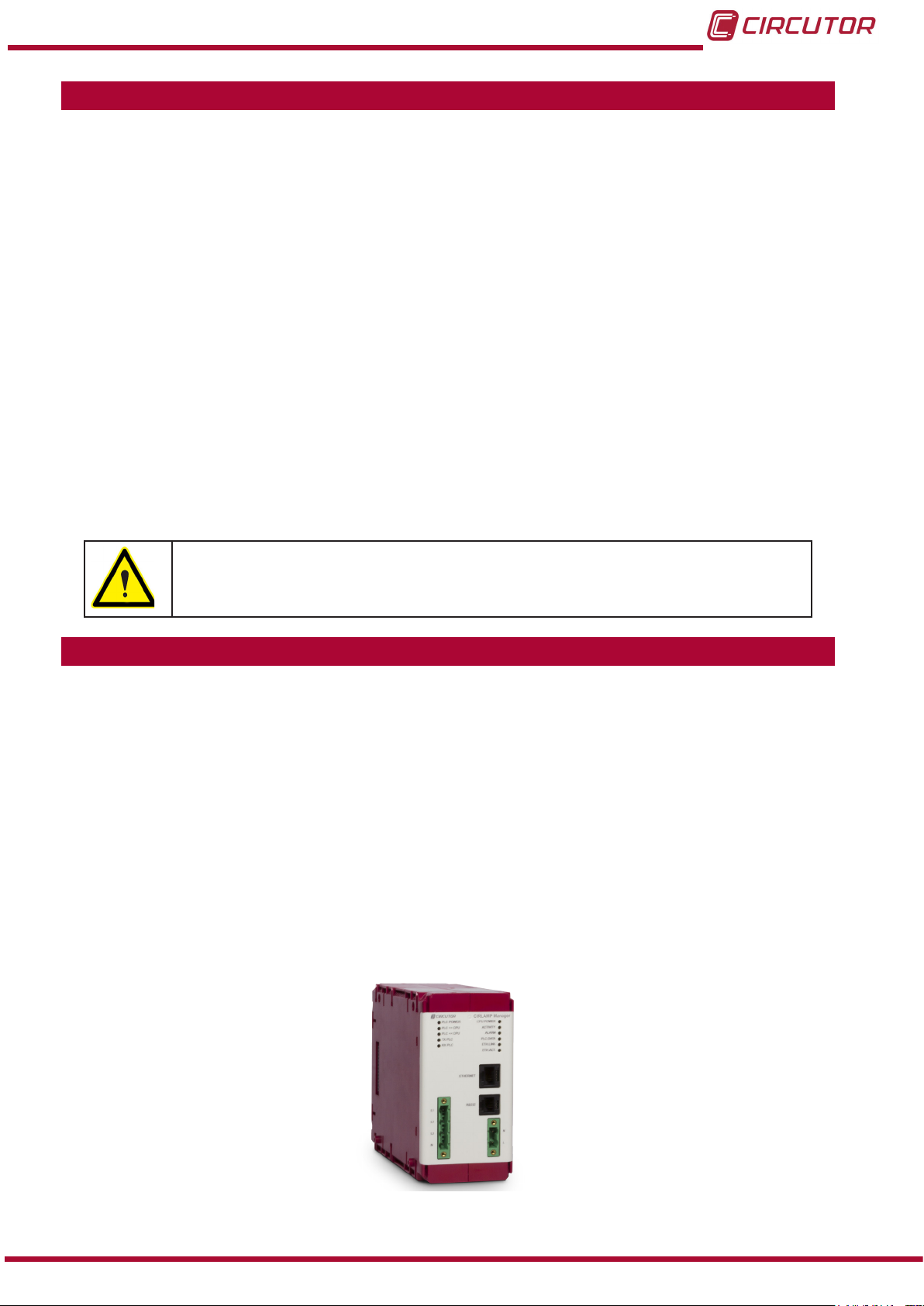
4�- CirLAMP Manager
4.1.- INSTALLATION OF THE UNIT
4�1�1� PRELIMINARY RECOMMENDATIONS
In order to use the unit safely, it is critical that individuals who handle it follow
the safety measures set out in the standards of the country where it is being
used, use the necessary personal protective equipment, and pay attention to
the various warnings indicated in this instruction manual.
The CirLAMP Manager unit must be installed by authorised and qualied staff.
The power supply plug must be disconnected before handling, altering the connections or
replacing the unit. It is dangerous to handle the unit while it is powered.
Also, it is critical to keep the cables in perfect condition in order to avoid accidents, personal
injury and damage to installations.
The manufacturer of the unit is not responsible for any damage resulting from failure by the
user or installer to observe the warnings and/or recommendations set out in this manual, nor
for damage resulting from the use of non-original products or accessories or those made by
other manufacturers.
If an anomaly or malfunction is detected in the unit, do not use it to perform any operation.
The unit must be disconnected from any power supply before carrying out any
maintenance or repairs, or handling any of the unit's connections.
Please contact the after-sales service if you suspect that there is an operational
fault in the unit.
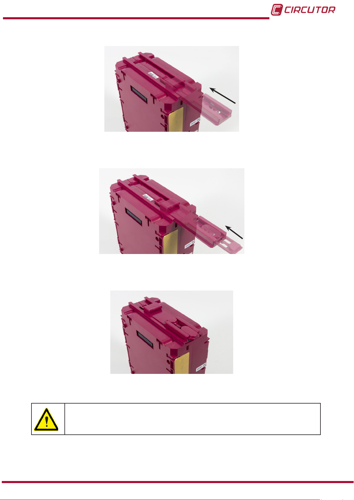
4�1�2� INSTALLATION
The CirLAMP Manager unit must be installed on an electric panel or enclosure, attached to a
DIN rail (IEC 60715).
10
Two DIN rail brackets are supplied with the unit and must be installed on the unit before insta-
lling it on the electric panel.
To do so, follow these steps:
Instruction Manual
Page 11
CirLAMP system
1�- Insert the rst bracket, as shown in Figure 1�
Figure 1: DIN rail brackets installation ( step 1)�
2�- Insert the second bracket in the rst bracket, Figure 2.
Figure 2: DIN rail brackets installation ( step 2)�
3�- Push the brackets into the rail until fully installed,Figure 3.
Figure 3: DIN rail brackets installation ( step 3)�
Terminals, opening covers or removing elements can expose parts that are
hazardous to the touch while the unit is powered. Do not use the unit until it is
fully installed.
The unit must be connected to a power circuit that is protected with gL fuses (IEC 269) or
M fuses, with a rating of 1 to 2 A. It must be tted with a circuit breaker or equivalent device
for disconnecting the unit from the power supply mains.
Instruction Manual
11
Page 12
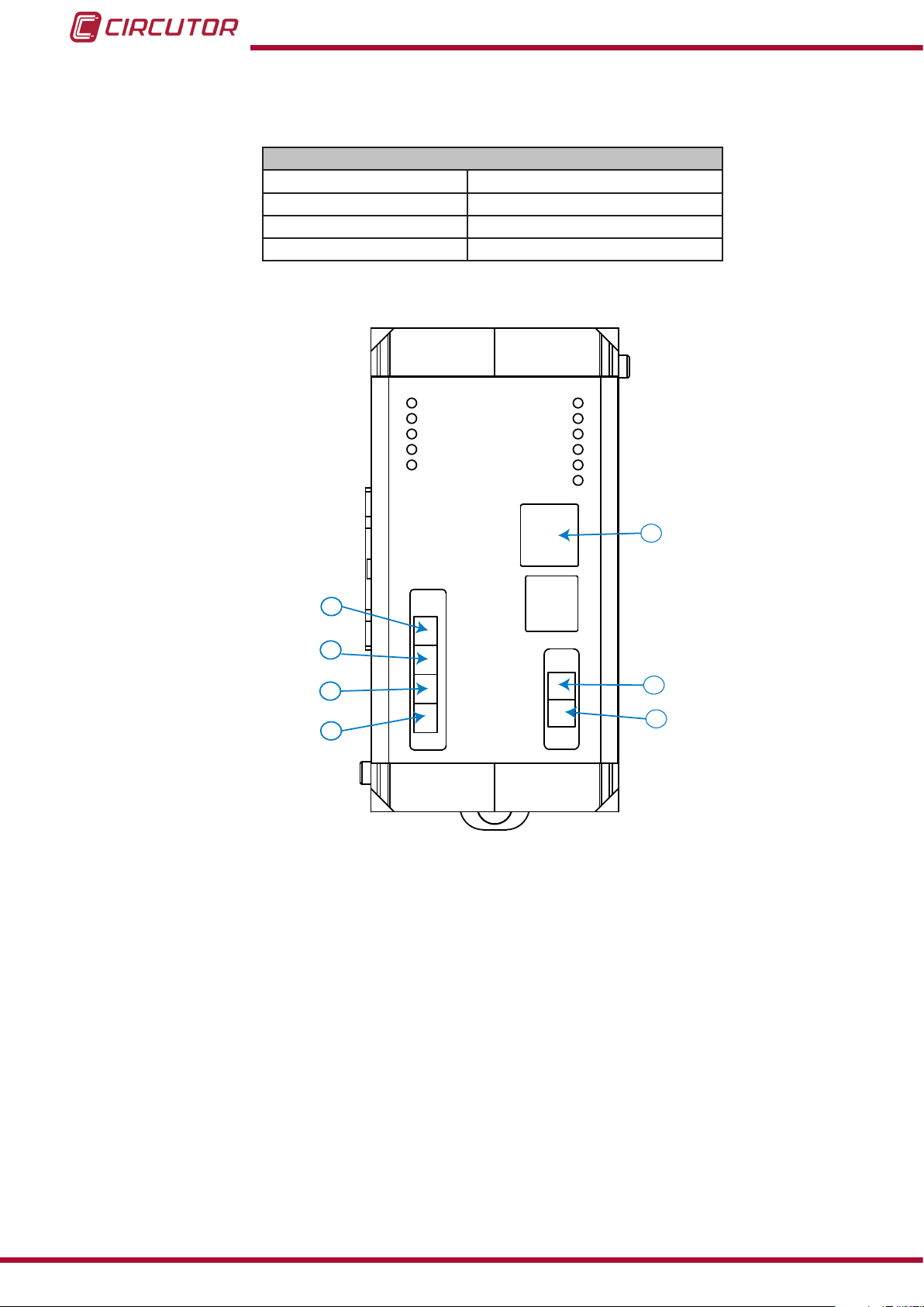
4�1�3� UNIT TERMINALS
1: L1, PLC connection L1 5: L, Auxiliary power supply
2: L2, PLC connection L2 6: N, Auxiliary power supply
3: L3, PLC connection L3 7: ETHERNET, Ethernet connection
4: N, PLC connection N
CirLAMP system
Table 2:List of CirLAMP Manager terminals�
Unit terminals
PLC POWER
PLC >> CPU
PLC << CPU
TX PLC
RX PLC
ETHERNET
CPU POWER
ACTIVITY
ALARM
PLC.DATA
ETH.LINK
ETH.ACT.
7
1
L1
2
3
4
L2
L3
N
N
L
6
5
12
Figure 4: CirLAMP Manager terminals�
Instruction Manual
Page 13
CirLAMP system
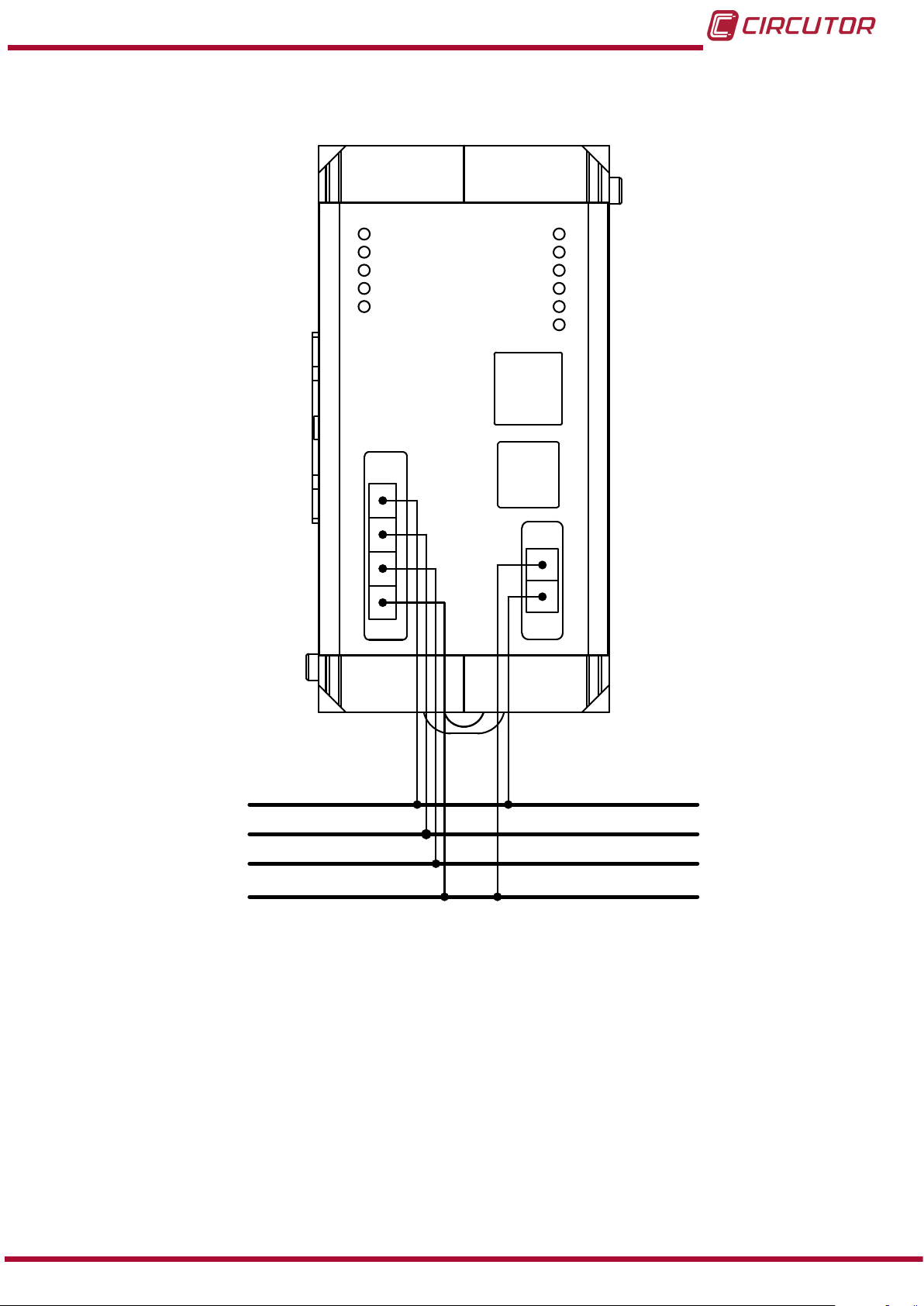
4�1�4� CONNECTION DIAGRAM
L1
L2
L3
N
PLC POWER
PLC >> CPU
PLC << CPU
TX PLC
RX PLC
CPU POWER
ACTIVITY
ALARM
PLC.DATA
ETH.LINK
ETH.ACT.
ETHERNET
N
L
L1
L2
L3
N
Figure 5: CirLAMP Manager connection diagram�
Instruction Manual
13
Page 14
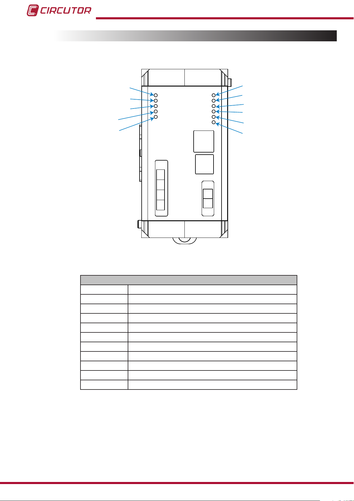
4.2.- LEDs
CirLAMP Manager has 11 indicator LEDs.
CirLAMP system
PLC POWER
PLC >> CPU
PLC << CPU
TX PLC
RX PLC
PLC POWER
PLC >> CPU
PLC << CPU
TX PLC
RX PLC
CPU POWER
ACTIVITY
ALARM
PLC.DATA
ETH.LINK
ETH.ACT.
ETHERNET
L1
L2
L3
N
Figure 6: CirLAMP Manager LEDs�
N
L
CPU POWER
ACTIVITY
ALARM
PLC DATA
ETH.LINK
ETH.ACT.
Table 3:List of CirLAMP Manager LEDs�
LEDs
PLC POWER Part of the connected PLC.
PLC>>CPU Communication from the PLC to the CirLAMP Manager.
PLC<<CPU Communication from the CirLAMP Manager to the PLC.
TX PLC Sending frames.
RX PLC Receiving frames.
CPU POWER CirLAMP Manager connected.
ACTIVITY The unit is performing a task.
ALARM An alarm has been activated.
PLC DATA Receiving frames.
ETH�LINK The Ethernet port is connected.
ETH�ACT Ethernet port activity.
14
Instruction Manual
Page 15

Restaurant
23
bakery
Restaurant
23
bakery
Restaurant
23
bakery
Restaurant
23
bakery
Restaurant
23
bakery
Restaurant
23
bakery
Restaurant
23
bakery23bakery
Restaurant
23
bakery
CirLAMP system
4.3.- PLC
The CirLAMP Manager uses PLC technology to communicate with the nodes (CirLAMP
Nodes) through the electrical network.
PLC (Power Line Communications) transfers data via the electrical network using advanced
modulation technology.
The PLC frequency bands are dened by different committees: FCC for North America and
Canada, ARIB for Asia and Japan and CENELEC for Europe.
The CirLAMP Manager works on Band B, from 95kHz to 125kHz, dened by CENELEC.
(European Committee for Electrotechnical Standardization).
PC
CIRLAMP
Manager
Comunicaciones PLC
Figure 7:Connection of a CirLAMP system via PLC�
Bombilla
Balasto/Driver
CIRLAMP
Nodo
F N
Control
4.4.- ETHERNET
The unit has an Ethernet port (terminal 7 in Figure 4), which can exchange information bidirectionally through the web server and transfer les through FTP, using TCP/IP type communications.
Instruction Manual
15
Page 16

4.5.- DATABASES
CirLAMP Manager has two databases:
4�5�1� MEASUREMENTS DATABASE
The measurements database comprises the following features:
A database for 1000 light points, with capacity to store 1 million logs.
Hardware: non-volatile memory without battery.
Non-volatile memory write policy to save maximum write cycles on FLASH memory.
Delete policy for oldest information.
Automatic node registration.
Automatic node withdrawal.
4�5�2� ALARM DATABASE
CirLAMP system
The alarm database comprises the following features:
Database for each light point with capacity for 50,000 logs.
Hardware: non-volatile memory without battery.
Non-volatile memory write policy to save maximum write cycles on FLASH memory.
Delete policy for oldest information.
4.6.- WEB SERVER
CirLAMP Manager has a conguration web site where the user can fully congure the conguration parameters of each light point. Furthermore, the unit has an XML server, so that it can
be integrated into any global control and maintenance platform.
4�6�1� HOME SCREEN
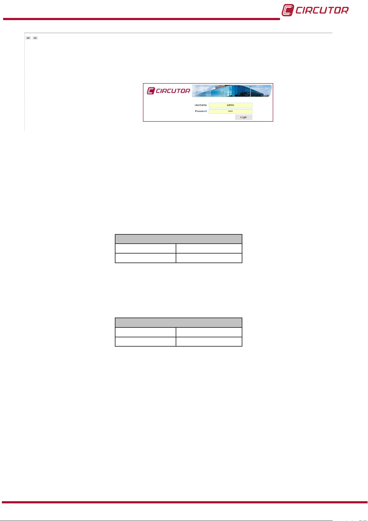
CirLAMP Manager is accessed via an Ethernet connection.
The default IP address of the unit is: 192�168�42�30.
It can also be accessed from a local IP on the Ethernet port: 100�0�0�1�
16
The web site detects the browser language. If the browser’s language is Spanish, the web site
will be shown in Spanish. Otherwise, the language will be English.
You can also select the language using the buttons that appear on the upper left part of the web
site (Figure 8).
Instruction Manual
Page 17
CirLAMP system
Figure 8: Homepage�
You must enter the correct username and password to enter the CirLAMP Manager web site.
CirLAMP Manager has two types of users:
1�- User with write access, admin:
With this access the user can read and write the CirLAMP Manager parameters as well
as those of the CirLAMP nodes installed.
Table 4: Default username and password for a user with write access�
Default username and password
Username admin
Password admin
2�- User with read access, user:
With this access, the user can only access certain read elds in CirLAMP Manager�
Table 5: Default username and password for a user with read access�
Default username and password
Username user
Password user
Instruction Manual
17
Page 18
CirLAMP system
4�6�2� MAIN SCREEN
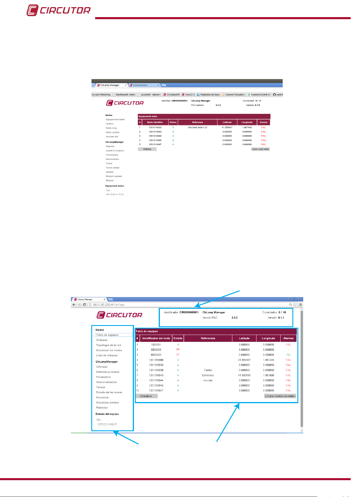
Figure 9 shows the web server's main screen, where you can access all the information relating
to the CirLAMP Manager and the CirLAMP Nodes installed.
Figure 9: Main screen�
The screen is divided into three areas of information (Figure 10):
CirLAMP Manager information area.
Menu for accessing all web screens.
Central area.
CirLAMP manager
information area
18
Menu Central area
Figure 10: Areas on the main screen�
Instruction Manual
Page 19
CirLAMP system
4�6�2�1 CirLAMP Manager information area�
Figure 11: CirLAMP Manager information area�
This area of the main screen shows all the information relating to CirLAMP Manager:
Identier: The unit identier is displayed (Example: CIR0000000001).
Name: Name given to the CirLAMP Manager. (Example:CirLamp Manager)
PLC version: PLC modem version.
Connected: Number of units connected/units detected.
Version: Firmware version of the CirLAMP Manager�
4�6�2�2 Menu
The CirLAMP Nodes and CirLAMP Manager screens can be accessed from the menu. The
unit status can also be viewed.
4�6�2�2�1� Menu: Nodes
Figure 12: Node selection menu�
The following screens can be accessed via the Nodes menu:
Equipments table: Accesses the table of nodes logged in the
CirLAMP Manager� (“4.6.3. NODES MENU: EQUIPMENTS TABLE”)
Orders: (“4�6�4� NODES MENU: ORDERS”)
Read access user: Cannot access the Orders screen.
Node map: Access the nodes map with the units connected at that instant.
(“4.6.5. NODES MENU: NODE MAP”)
Node update: Update nodes screen. (“4.6.6. NODES MENU: NODE UPDATE”)
Intruder list: Allows you to add the nodes that you do not wish to connect to CirLAMP
Manager to a list using the serial number of each node.
(“4.6.7. NODES MENU: INTRUDER LIST”)
Read access user: Cannot access the Intrusion list screen.
Instruction Manual
19
Page 20

4�6�2�2�2� Menu: CIRLAMP Manager
Figure 13:CirLAMP Manager selection menu�
The following screens can be accessed from the CirLAMP Manager:
Reports: Accesses documents containing information on CirLAMP Manager�
(“4.6.8. CirLAMP MANAGER MENU: REPORTS”)
CirLAMP system
Inputs and outputs: (If the M8I8O expansion module is not connected, this option
does not appear ). Up to 8 inputs and outputs can be congured.
(“4.6.9. CirLAMP MANAGER MENU: INPUTS AND OUTPUTS”)
Read access user: This option does not appear in the selection menu.
Parameters: Provides access to the conguration of the CirLamp�
Manager (“4.6.10. CirLAMP MANAGER MENU: PARAMETERS”)
Read access user: This option does not appear in the selection menu.
Geolocation: Accesses the unit geolocation screen.
(“4.6.11. CirLAMP MANAGER MENU: GEOLOCATION”).
Read access user: This option does not appear in the selection menu.
Tasks: Accesses the unit tasks conguration screen.
( “4.6.12. CirLAMP MANAGER MENU: TASKS”)
Read access user: This option does not appear in the selection menu.
Task status: This button accesses the status screen for the
CirLAMP Manager tasks.
(“4.6.13. CirLAMP MANAGER MENU: TASK STATUS”)
Read access user: This option does not appear in the selection menu.
Update: Accesses the unit update screen.
(“4.6.14. CirLAMP MANAGER MENU: UPDATE”)
Read access user: This option does not appear in the selection menu.
20
Modem update: Accesses the screen for updating the unit's modem driver.
(“4.6.15. CirLAMP MANAGER MENU: MODEM UPDATE”)
Read access user: This option does not appear in the selection menu.
Reboot: Accesses the unit restart screen.
(“4.6.16. CirLAMP MANAGER MENU: REBOOT”)
Read access user: This option does not appear in the selection menu.
Instruction Manual
Page 21
CirLAMP system
4�6�2�2�3� Equipment status
Figure 14:Unit status�
This section displays the CirLAMP Manager status or task in progress, as well as the current
time on the unit.
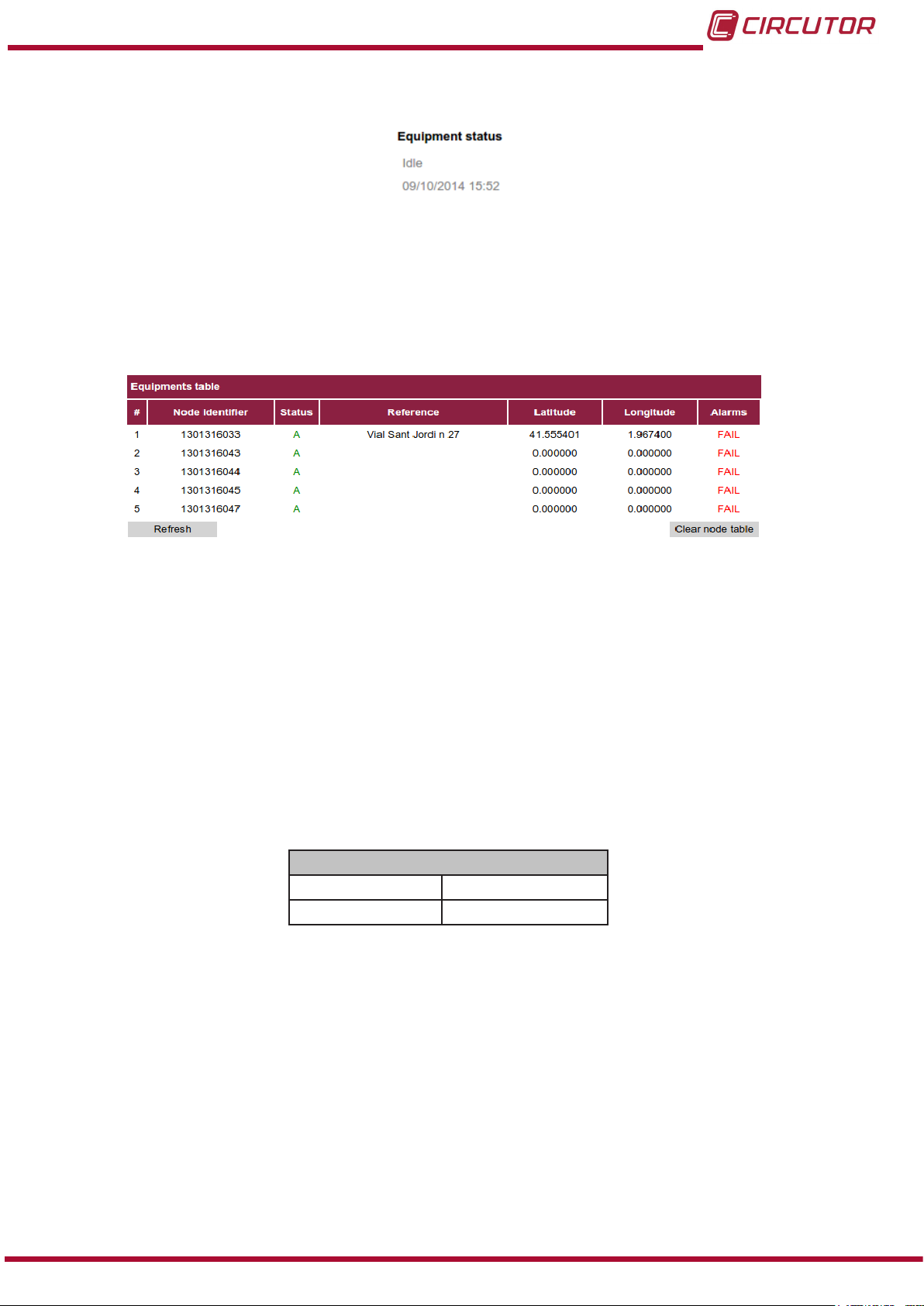
4�6�3� NODES MENU: EQUIPMENTS TABLE
Figure 15:Table of units�
This screen shows a table with all the CirLAMP Nodes logged in the CirLAMP Manager�
As seen in Figure 15, the table includes the following elds:
#: This column correlatively lists the units logged in the CirLAMP Manager�
Node identier: unit's serial number.
Status: current status of the unit. Two states are possible, see Table 6:
Table 6: Possible node states�
Status
A Active
PF Permanent fault
Reference: reference assigned to a node to help identify it.
Latitude: latitude assigned to the node.
Longitude: longitude assigned to the node.
Instruction Manual
21
Page 22
CirLAMP system
Alarms: current status of the node. Two states are possible, see Table 7:
Table 7: Alarms�
Status
OK No alarms
FAIL Node fault
NB: There is an application for iOS and Androids for positioning the nodes.(CirLAMP NODE
Location)
There are two buttons in the lower part of the table, with the following functions (Table 8):
Table 8: Buttons on the table of units�
Button Function
Update Updates the current content of the table of units.
Removes all nodes that are not active (Status: PF)
Clean the nodes table
from the CirLAMP Manager database.
If the nodes reconnect to the network at a later date,
they will automatically appear in the table of units.
To access all the information available relating to a node, click on the row for the selected unit.
See “4.6.3.1. Node information menu”
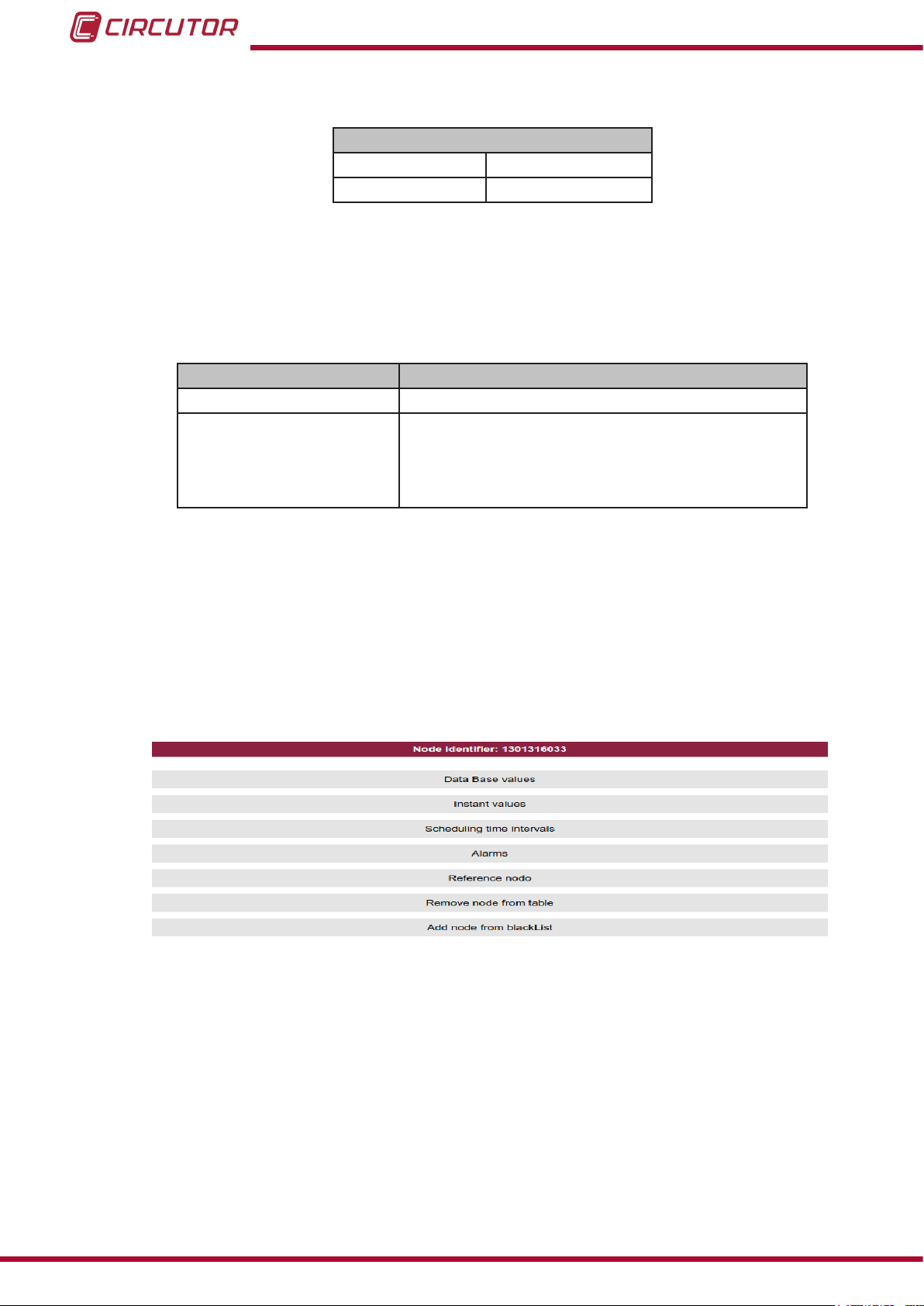
4�6�3�1� Node information menu
All the parameters of a CirLAMP Node can be viewed and congured from this screen.
The menu varies depending on the type of user used to enter the web site (Figure 16 and
Figure 17).
Figure 16:Node information menu (Write access user)�
22
Instruction Manual
Page 23
CirLAMP system
Figure 17:Node information menu (Read access user)�
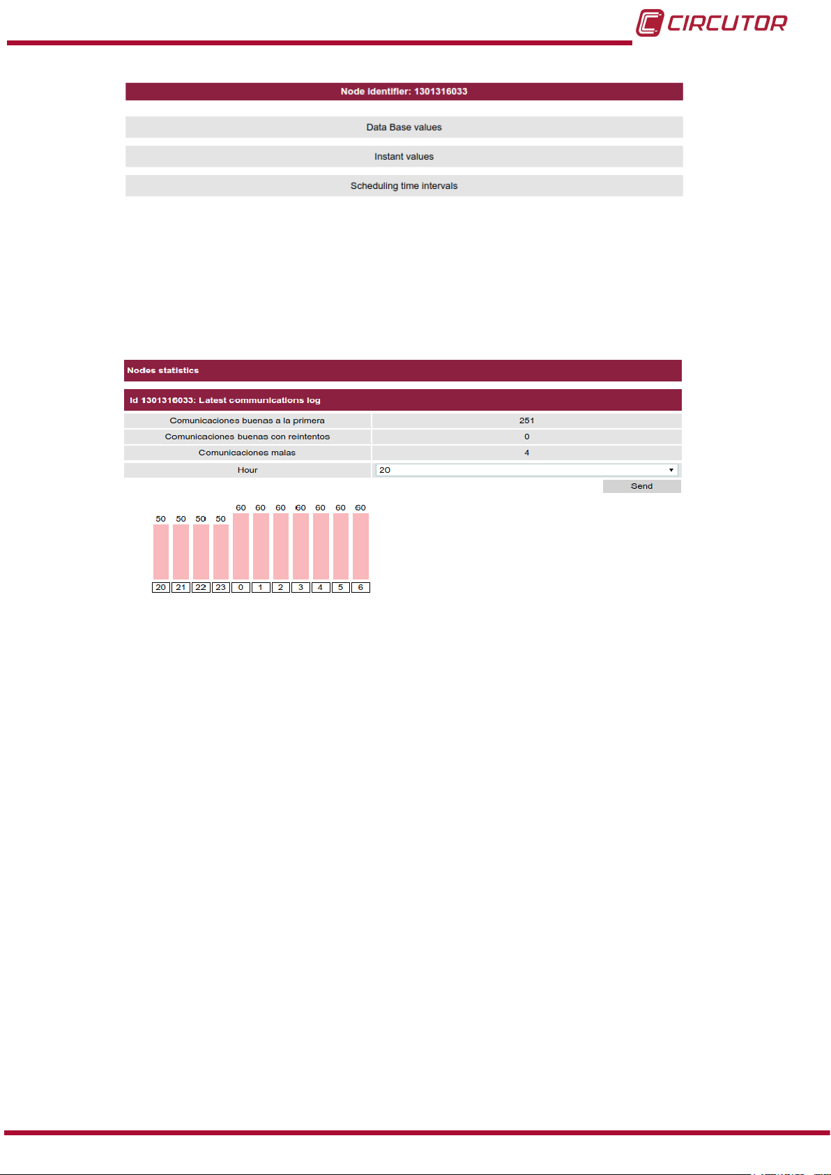
4�6�3�1�1� Database values
On this screen Figure 18 you can view the node data for the last 24 hours. You can select any
time on the graph and see instantaneous values for the unit at that time.
Figure 18:Database values screen�
Instruction Manual
23
Page 24
CirLAMP system
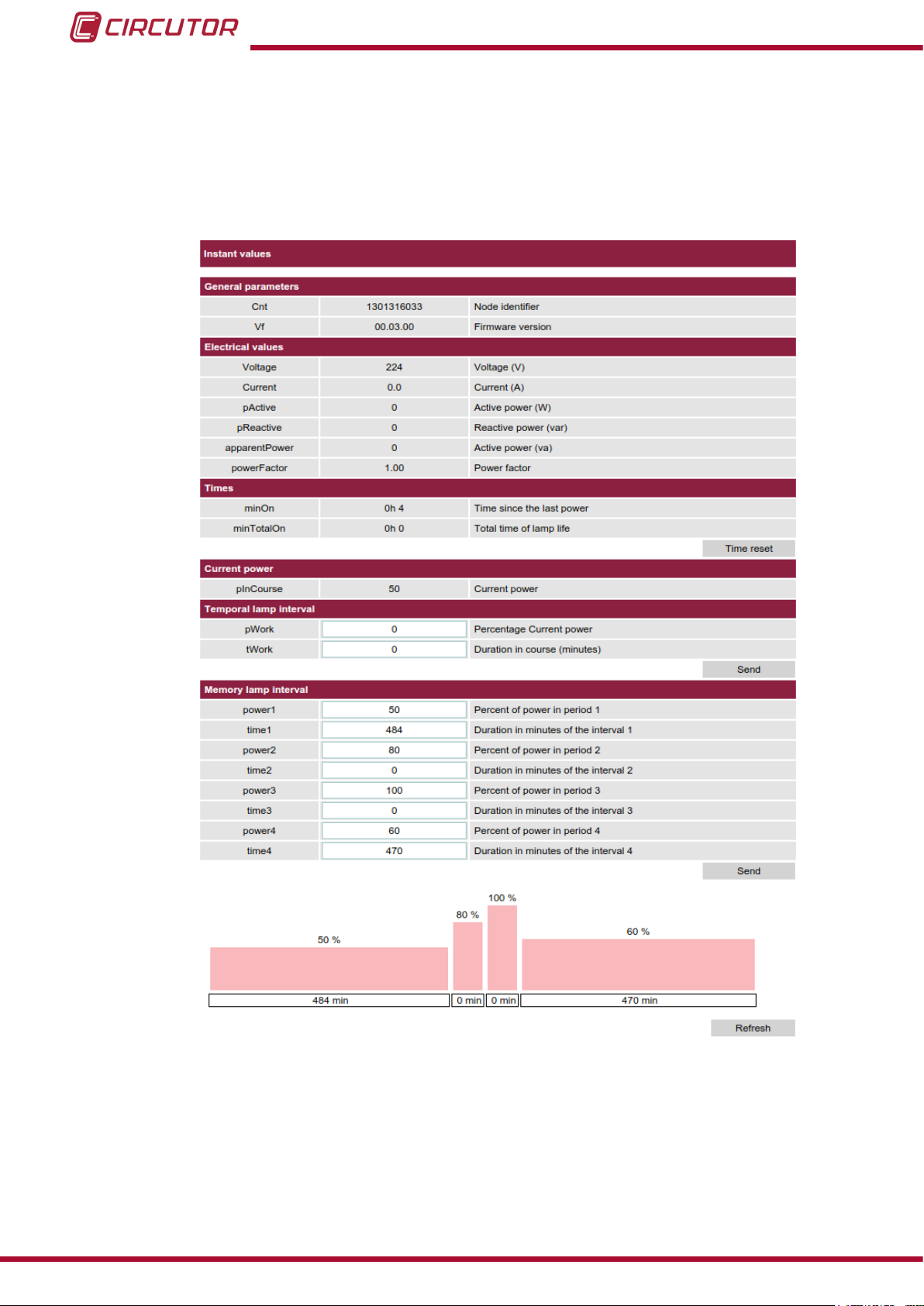
4�6�3�1�2� Instant values
On this screen, Figure 19, you can view the instantaneous consumption values and congure
the work time interval and memory work interval for each node.
NB: If the node is stopped the CirLAMP Manager cannot provide the data.
24
Figure 19:Instant values screen�
General parameters:
This section displays the identier and rmware version for the node selected.
Electric values:
This section displays the following electrical parameters:
Instruction Manual
Page 25

CirLAMP system
Table 9: Electrical parameters�
Parameter Units
Voltage: Voltage V
Current: Current A
pActive: Active power W
pReactive: Reactive power var
Times:
This section displays:
minOn: Time from the last switch on.
minTotalOn: The total useful life of the node.
Clicking on the Delete time button resets the two parameters.
Current power:
Is the power (in %) of the node at the moment when the instantaneous values are read.
Temporal lamp interval:
In this section you can congure:
pWork: Value of the power (in %) during the period determined by tWork�
tWork: Time interval in minutes for which we want the power value dened in pWork�
Click on the Send button to send the data to the unit.
NB: The parameters for the work time interval are not saved when the power supply is dis-
connected from the node.
Memory lamp interval:
In this section four different power intervals can be congured. The remaining time starts to
count down when the power supply is connected to the node.
power1: Power value in % during interval 1.
time1: Duration in minutes of interval 1.
power2: Power value in % during interval 2.
time2: Duration in minutes of interval 2.
power3: Power value in % during interval 3.
time3: Duration in minutes of interval 3.
power4: Power value in % during interval 4.
time4: Duration in minutes of interval 4.
Click on the Send button to send the data to the unit.
NB: The parameters for the memory work interval are not saved when the power supply is
disconnected from the node.
Read access user: The Delete time button is not enabled and the work time interval or the
work memory interval cannot be modied.
Instruction Manual
25
Page 26
CirLAMP system
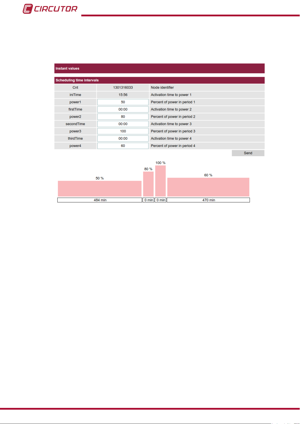
4�6�3�1�3� Scheduling time intervals in hours
If the CirLAMP Manager has the input and output module (M8I8O Expansion module) the
work intervals can be programmed automatically from Sunrise (Sunrise time).
Figure 20:Screen for scheduling time intervals in hours�
The parameters are:
Cnt: Node identier.
inTime: Interval 1 activation time. This parameter cannot be modied; it coincides
with the Sunrise value (Sunrise time).
power1: Power value in % during interval 1.
rstTime: Interval 2 activation time.
power2: Power value in % during interval 2.
secondTime: Interval 3 activation time.
power3: Power value in % during interval 3.
thirdTime: Interval 4 activation time.
power4: Power value in % during interval 4. Interval 4 will last until the node has
no power supply.
Click on the Send button to send the data to the unit.
Read access user: The programming of intervals in hours cannot be modied.
26
Instruction Manual
Page 27
CirLAMP system
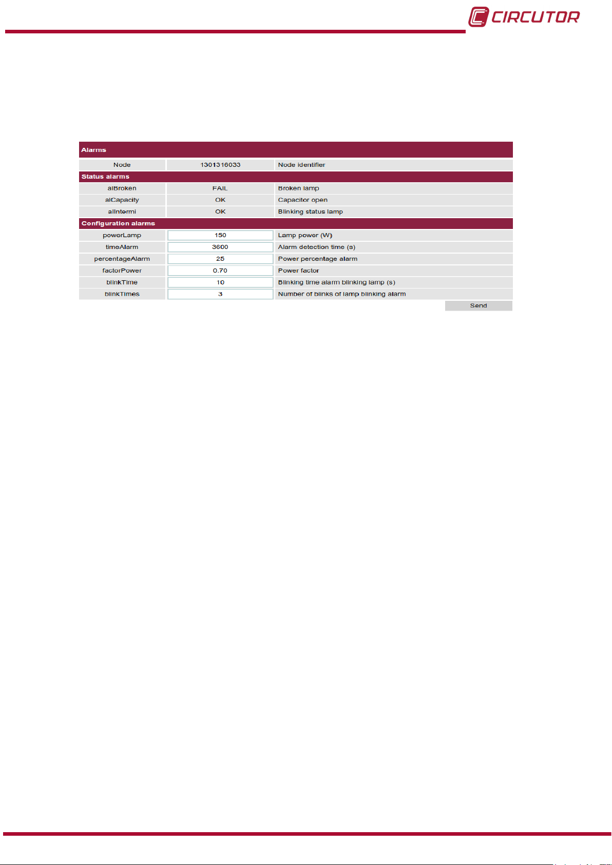
4�6�3�1�4� Alarms
Read access user: Cannot access the Alarms screen.
On this screen, Figure 21, you can view and congure the node alarms.
Figure 21:Alarm screen�
Status alarms:
Each CirLAMP node has the following alarms:
Detection of burnt out lamp (alBroken)
Each CirLAMP node detects the anomalous operation of each light. If the lamp is burnt
out the node detects this and generates an alarm.
Open capacitor detection and alert (alCapacity)
A malfunction or anomalous operation may be due to a deteriorated PFC capacitor. This
causes high consumption of inductive reactive power, which is detected after it has remained active for 1 hour.
Blinking lamp detection and alert (alIntermi)
Depending on the type of lamp, once it has reached the end of its useful life, it does not
switch off but starts to switch on intermittently, the CirLAMP detects this anomalous
situation and activates the alIntermi alarm if the lamp switches off more than a program-
mable number of times over a period of 2 hours.
Value 1 in the alarm status column indicates that the alarm is activated.
Conguration alarms:
The conguration parameters for the alarm are:
powerLamp, lamp power in W.
timeAlarm, alarm detection time.
percentageAlarm, value of the percentage of power under which the alarm will be
activated.
factorPower, node power factor value.
blinkTime, bulb blinking time to activate the alIntermi alarm.
blinkTimes, number of bulb blinks to activate the alIntermi alarm.
Instruction Manual
27
Page 28
CirLAMP system
4�6�3�1�5� Reference node
Read access user: Cannot access the Reference node screen.
On this screen, Figure 22, you can view and modify the node reference, i.e, the identifying text
to differentiate it from the other nodes in the installation.
Figure 22:Reference node
4�6�3�1�6� Remove node from the table
Read access user: Cannot access the Remove node from the table screen.
Clicking on this button deletes the node from the table of units and the database.
If the node reconnects to the network at a later date, it will automatically appear in the table of
units.
Figure 23:Remove node from the table�
4�6�3�1�7� Add node from blackList
Read access user: Cannot access the Add node from blackList screen.
Clicking on this button deletes the node from the table of units and database and adds it to the
intrusion list.
Units which are included in the intrusion list will not be registered in the nodes table again until
they are deleted from the intrusion list.
Figure 24:Add node from blackList�
28
Instruction Manual
Page 29
CirLAMP system
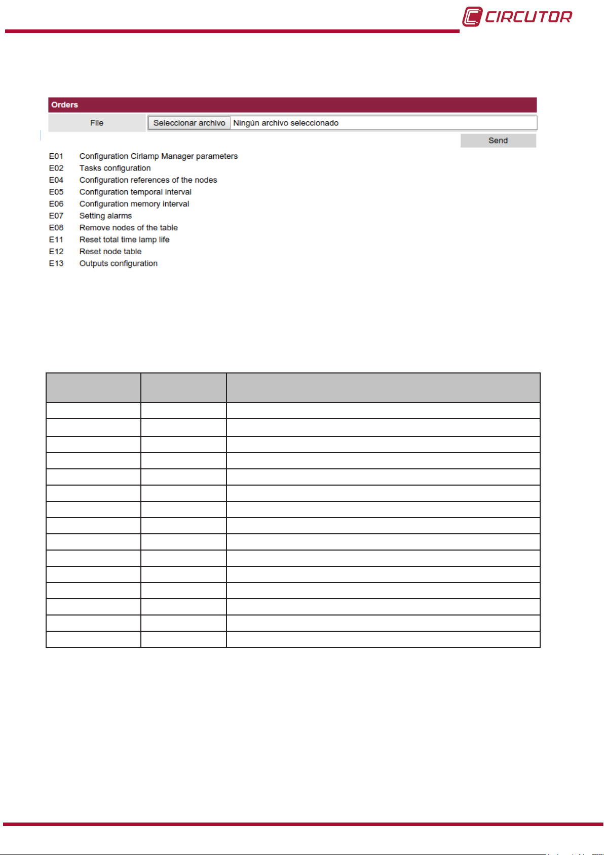
4�6�4� NODES MENU: ORDERS
On this screen, Figure 25, you can select the orders le that you want to send to the unit.
Figure 25:Orders screen�
The orders les are in .xml format.
The orders les that can be created in CirLAMP Manager are detailed in Table 10.
Table 10: Orders available for CirLAMP Manager�
Code
Write le
E01 L01 Conguration of parameters
E02
E03 - Update rmware.
E04 L04 Nodes references.
E05 L05 Work time interval.
E06 L06 Memory interval.
E07 L07 Alarm adjustment.
E08 L08 Delete nodes from list.
E09 - Manage the nodes black list.
E11 L11 Set the total useful life for node lamps to 0.
E12 L12 Delete all nodes from the network.
E13 L13 Manage the inputs/outputs module.
- L14 List of spontaneous events.
E17 L17 Memory time interval, via time conguration.
C06 - Modication of date in CirLAMP Manager.
Code
Read le
L02
Description
Conguration of tasks.
Instruction Manual
29
Page 30

CirLAMP system
4.6.4.1. E01-L01, Conguration of parameters
Format of le E01 (Figure 26):
<Order IdReq=”E01” IdPet=”(UInt32)” Version=”3�1”>
<CirLamp Id=”CIR4600000001”>
<E01 netId=”Val” name=”CirLamp Manager” DCPwdAdm=”Val” DCPwdRead=”Val” ipCom=”Val” PortWS=”(integer)” ipMask=”Val” ipGtw=”(string)” ipDhcp=”Y/N” ipLoc=”Val” ipMaskLoc=”Val” Pse=”(val)” Priority=”Val” IPNTP=”(val)” IPftp=”(val)” FTPUser=”Val” FTPPwd=”Val” RetryFtp=”(integer)” TimeSendReq=”(integer)”
TimeDisconMeter=”Val” TimeRetryInterval=”(integer)” ReportFormat=”Y/N” ValuesCheckDelay=”(seconds)” MaxOrderOutdate=”(integer)” TimeDelayRestart=”(integer)”
NTPMaxDeviation=”(integer)” AccInacTimeout=”(integer)” AccSimulMax=”(integer)”
PrimaryDns=”(val)” SecondaryDns=”(val)” PathReports=”(string)” TimeZone=”(integer)” mailHost=”MAILHOST” mailUser=”(string)” mailPassword=”(string)” mainMail=”(string)” destinationMail=”(string)” hourIni=”(val)” hourEnd=”(val)” activeFilterTime=”(val)” latitude=”(val)” longitude=”(val)” viewNodes=”Y”>
</E01>
</CirLamp>
</Order>
Figure 26: File E01�
Format of le L01 (Figure 27):
<Report IdRpt=” L01” IdPet=”0” Version=”3�1”>
<CirLamp Id=”CIR4600000001”>
<L01 Fh=”20120914093550S” netId=”1” name=”CirLamp Manager” Mod=”CirLampManager” Af=”2012” Vf=”0�0�1” VfComm=”2220” ipCom=”10�0�120�212”
PortWS=”8080” ipMask=”255�255�255�0” ipGtw=”10�0�120�254” ipDhcp=”N” ipLoc=”100�0�0�1” ipMaskLoc=”255�255�255�0” Pse=”38400” Priority=”Y” IPNTP=”0�
pool�ntp�org” IPftp=”” FTPUser=”DCUPLOAD” FTPPwd=”DCUPLOAD” RetryFtp=”2”
TimeBetwFtp=”10” TimeSendReq=”3600” TimeDisconMeter=”300” RetryDisconMeter=”3” TimeRetryInterval=”15” ReportFormat=”Y” ValuesCheckDelay=”5” MaxOrderOutdate=”300” TimeDelayRestart=”60” NTPMaxDeviation=”30” AccInacTimeout=”20”
AccSimulMax=”10” PrimaryDns=”8�8�8�8” SecondaryDns=”8�8�4�4” PathReports=”/upload” TimeZone=”0” mailHost=”MAILHOST” mailUser=”MAILUSER” mailPassword=”MAILPASSWORD” mainMail=”mainmail@mail�es” destinationMail=“destination@mail�
es” hourIni=”0” hourEnd=”0” activeFilterTime=”N” latitude=”149620�000000” longitude=”7229�000000” viewNodes=”Y”>
</L01>
</CirLamp>
</Report>
Figure 27: File L01�
Where:
30
Root element: <Report/Order>
<Report/Order> is the root element of the le. Its attributes indicate the data necessary to
process the le:
Instruction Manual
Page 31

CirLAMP system
Table 11:File E01-L01, <Report/Order> element
Attribute Description
IdRpt/IdReq Report/order identier.
IdPet Single identier for the order.
Version Version identier.
Container element: <CirLamp>
< CirLamp> is the container element for the report order:
Table 12:File E01-L01, <CirLamp> element
Attribute Description
Id CirLamp Manager identier.
Container element: < L01/E01>
< L01/E01> is the container element for all CirLAMP Manager parameters:
Table 13:File E01-L01, <Report/Order> element
Attribute Description
name Name assigned to the CirLAMP Manager�
Fh Date (Y/M/D H:M:S). (read parameter)
netId Network identier.
Mod Unit model. (read parameter)
AF Year of manufacture. (read parameter)
DCPwdAdm Administrator user password.
DCPwdRead Read user password.
Vf Firmware version. (read parameter)
VfComm PLC version. (read parameter)
ipCom CirLamp Manager IP.
PortWS Communications port used when communicating through the Web
Server (Example: 8080).
ipMask Subnet mask IP. (Used if the DHCP is disabled)
ipGtw Gateway IP. (Used if the DHCP is disabled)
ipDhcp Indicates whether the DHCP is enabled (Y) or disabled (N).
ipLoc Additional internal IP to the one previously named.
ipMaskLoc Local subnet mask.
Pse Serial port speed. (Read parameter)
Priority Priority is enabled (Y) or disabled (N).
IPNTP IP address for synchronisation with the NTP server.
IPftp
IP address of the FTP server where you can download and upload
reports.
FTPUser Username for accessing the FTP.
FTPPwd Password for accessing the FTP.
RetryFyp Number of retries to access the FTP servers.
TimeBetwFtp Time between retries when accessing the FTP server.
Instruction Manual
31
Page 32

CirLAMP system
Attribute Description
Maximum time for sending a report. If the report read time is higher
TimeSendReq
TimeDisconMeter
RetryDisconMeter
TimeRetryInterval Time between reattempts to communicate with the units.
ReportFormat Indicates the format of the reports: compressed (1), normal (0).
ValuesCheckDelay Number of seconds delay to execute an order.
MaxOrderOutdate
TimeDelayRestart
NTPMaxDeviation
AccInacTimeout Period of inactivity before the WEB session ends. (minutes)
AccSimulMax Maximum number of simultaneous users on the WEB.
PrimaryDns Primary DNS IP address.
SecondaryDns Secondary DNS IP address.
PathReports Directory for uploading the le to the FTP.
TimeZone
mailHost Mail server.
mailUser Mail user.
mailPassword Mail password.
mainMail Address from which mail is sent.
destinationMail Address to which mail is sent.
hourIni Start time for communication with the tasks.
hourEnd End time for communication with the tasks.
activeFilterTime
latitude CirLAMP Manager latitude.
longitude CirLAMP Manager longitude.
viewNodes
than indicated, a report containing the information collected to date
will be sent and it will continue to read the information until it is complete. (seconds)
If the time of the last communication exceeds the time indicated by
this variable, the unit will change from active to inactive. (seconds)
Number of retries to communicate with the nodes connected to the
CirLAMP Manager network.
Maximum time to initiate an order, i.e., if an order is programmed
with an initiate execution time higher than this value, the order will
be aborted. (seconds)
Wait time before continuing with tasks after starting the unit. (seconds)
The unit will generate an event when the deviation in seconds, between the NTP and the unit, is greater than that indicated.
Time zone:
0 : Barcelona, 1: London, 2: Athens, 3: Argentina, 4: Brazil
5 : Colombia, 6: Central America.
The lter for the tasks communication time is enabled (Y) or disabled (N).
Indicates whether you want to view the CirLAMP Nodes on the
map or not.
32
Instruction Manual
Page 33

CirLAMP system
4.6.4.2. E02-L02, Conguration of tasks
Format of le E02 (Figure 28):
<Order IdRpt=”E02” IdPet=”0” Version=”3�1”>
<CirLamp Id=”CIR4600000001”>
<E02>
<TP TpTar=”1” TpHi=”20120915011000S” TpPer=”00000001000000” TpCompl=”Y” TpPrio=”2”>
<TpPro TpReq=”L01” TpSend=”Y” TpStore=”Y”>
<TpAttr/>
</TpPro>
</TP>
</E02>
</CirLamp>
</Order>
Figure 28: File E02�
Format of le L02 (Figure 29):
<Report IdRpt=”L02” IdPet=”0” Version=”3�1”>
<CirLamp Id=”CIR4600000001”>
<L02>
<TP TpTar=”1” TpHi=”20120915011000S” TpPer=”00000001000000” TpCompl=”Y” TpPrio=”2”>
<TpPro TpReq=”L01” TpSend=”Y” TpStore=”Y”>
<TpAttr/>
</TpPro>
</TP>
</L02>
</CirLamp>
</Report>
Figure 29: File L02�
Where:
Root element: <Report/Order>
<Report/Order> is the root element of the le. Its attributes indicate the data necessary to
process the le:
Table 14:File E02-L02, element <Report/Order>
Attribute Description
IdRpt/IdReq Report/order identier.
IdPet Single identier for the order.
Version Version identier.
Container element: <CirLamp>
< CirLamp> is the container element for the report order:
Table 15:File E02-L02, element <CirLamp>
Attribute Description
Id CirLamp Manager identier.
Instruction Manual
33
Page 34

CirLAMP system
Container element: < L02/E02>
< L02/E02> is the container element for information relating to the conguration of the tasks.
Container element: < TP>
< TP> is the container element for information relating to a task:
Table 16:File E02-L02, element <TP>
Attribute Description
TpTar Task identication number.
Task start time. Format: YYYYMMDDHHmmssX
TpHi
TpPer Frequency, time between queries. Format: YYYYMMDDHHmmss.
TpPrio
A : year, M: month, D: day, H: hour, m: minute, s: second
X: summer (S) or winter (W).
Task priority.
1 : Maximum priority. 2: Normal priority. 3: Low priority.
Container element: < TPPro>
< TPPro> is the container element for information relating to a report:
Table 17:File E02-L02, element <TPPro>
Attribute Description
TpReq Report created in this task.
TpSend
TpStore Frequency, time between queries. Format: YYYYMMDDHHmmss.
Indicates whether the report obtained is sent to the FTP server or not.
Y: The le is sent. N: The le is not sent.
4.6.4.3. E03, Update rmware
Format of le E03 (Figure 30):
<Order IdReq=”E03” IdPet=”(UInt32)” Version=”3�1”>
<CirLamp Id=”CIR4600000001”>
<E03 ActDate=”20100101001500000W” Firmware=”(String)”/>
</CirLamp>
</Order>
Figure 30: File E03�
Where:
34
Root element: <Order>
Order> is the root element of the le. Its attributes indicate the data necessary to process the
le:
Table 18:File E03, element <Order>
Attribute Description
IdRpt/IdReq Report/order identier.
IdPet Single identier for the order.
Version Version identier.
Instruction Manual
Page 35

CirLAMP system
Container element: <CirLamp>
< CirLamp> is the container element for the report order:
Table 19:File E03, element <CirLamp>
Attribute Description
Id CirLamp Manager identier.
Container element: < E03>
< E03> is the container element for information relating to the updating of the unit:
Table 20:File E03, element <E03>
Attribute Description
ActDate Activation date for the update rmware order.
Firmware File download path required to update the CirLAMP Manager�
4�6�4�4� E04-L04, Nodes reference
Format of le E04 (Figure 31):
<Order IdReq=”E04” IdPet=”1” Version=”3�1”>
<CirLamp Id=”CIR0000001”>
<E04>
<Node nodeId=”1000001” Reference=”Street X n1” latitude=”37�6737” longitude=”-4�93”/>
</E04>
</CirLamp>
</Order>
Figure 31: File E04�
Format of le L04 (Figure 32):
<Report IdRpt=”L04” IdPet=”1” Version=”3�1”>
<CirLamp Id=”CIR0000000001”>
<L04 Fh=”20121113121605W”>
<Node nodeId=”9000009” Reference=”Vial Sant Jordi n 48” latitude=”37�6737” longitude=”-4�93”/>
</L04>
</CirLamp>
</Report>
Figure 32: File L04�
Where:
Root element: <Report/Order>
<Report/Order> is the root element of the le. Its attributes indicate the data necessary to
process the le:
Instruction Manual
35
Page 36

CirLAMP system
Table 21:File E04-L04, element <Report/Order>
Attribute Description
IdRpt/IdReq Report/order identier.
IdPet Single identier for the order.
Version Version identier.
Container element: <CirLamp>
< CirLamp> is the container element for the report order:
Table 22:File E04-L04, element <CirLamp>
Attribute Description
Id CirLamp Manager identier.
Container element: < L04/E04>
< L04/E04> is the container element for information relating to the reference for the network
nodes.
Container element: < Node>
< Node> is the container element for information relating to a node:
Table 23:File E04-L04, element <Node>
Attribute Description
nodeId Node identier.
Reference Node reference for better physical localisation of the node.
latitude CirLAMP Node latitude.
longitude CirLAMP Node longitude.
4�6�4�5� E05-L05, Work time interval
Format of le E05 (Figure 33):
<Order IdReq=”E05” IdPet=”2” Version=”3�1”>
<CirLamp Id=”CIR0000001”>
<E05 ActDate=”20121114165000000W”>
<Node nodeId=”9000009”>
<Interval time=”60” power=”59”/>
</Node>
</E05>
</CirLamp>
</Order>
Figure 33: File E05�
36
Instruction Manual
Page 37

CirLAMP system
Format of le L05 (Figure 34):
<Report IdRpt=”L05” IdPet=”148” Version=”3�1”>
<CirLamp Id=”CIR0000000001”>
<L05 Fh=”20140310154742W”>
<Node Id=”1301250033” Fh=”20140310154733W” time=”0” power=”0”>
<Node Id=”1301316033” Fh=”20140310154734W” time=”0” power=”0”>
<Node Id=”1301316039” Fh=”20140310154735W” time=”0” power=”0”>
<Node Id=”1301316043” Fh=”20140310154737W” time=”0” power=”0”>
</L05>
</CirLamp>
</Report>
Figure 34: File L05�
Where:
Root element: <Report/Order>
<Report/Order> is the root element of the le. Its attributes indicate the data necessary to
process the le:
Table 24:File E05-L05, element <Report/Order>
Attribute Description
IdRpt/IdReq Report/order identier.
IdPet Single identier for the order.
Version Version identier.
Container element: <CirLamp>
< CirLamp> is the container element for the report order:
Table 25:File E05-L05, element <CirLamp>
Attribute Description
Id CirLamp Manager identier.
Container element: < L05/E05>
< L05/E05> is the container element for information relating to the work time interval:
Table 26:File E05-L05, element <L05/E05>
Attribute Description
ActDate Order activation date.
Container element: < Node>
< Node> is the container element for information relating to a node:
Table 27:File E05-L05, element <Node>
Attribute Description
nodeId Node identier.
Container element: < Interval>
< Interval> is the container element for information relating to the work time interval:
Instruction Manual
37
Page 38

CirLAMP system
Table 28:File E05-L05, element <Interval>
Attribute Description
time Duration in minutes for the work time interval.
power % of power in the work time interval.
4�6�4�6� E06-L06, Memory work interval
Format of le E06 (Figure 35):
<Order IdReq=”E06” IdPet=”5” Version=”3�1”>
<CirLamp Id=”CIR0000001”>
<E06 ActDate=”20121114165000000W”>
<Node nodeId=”9000009”>
<Interval time1=”10” power1=”57” time2=”10” power2=”79”
time3=”50” power3=”80” time4=”50” power4=”99”/>
</Node>
</E06>
</CirLamp>
</Order>
Figure 35: File E06�
Format of le L06 (Figure 36):
<Report IdRpt=”L06” IdPet=”148” Version=”3�1”>
<CirLamp Id=”CIR0000000001”>
<L06 Fh=”20140310155200W”>
<Node Id=”1301250033” Fh=”20140310155150W” time1=”552” power1=”100” time2=”330” power2=”70” time3=”310” power3=”50” time4=”98” power4=”100”/>
<Node Id=”1301316033” Fh=”20140310155152W” time1=”552” power1=”100” time2=”330” power2=”70” time3=”310” power3=”50” time4=”98” power4=”100”/>
</L06>
</CirLamp>
</Report>
Figure 36: File L06�
Where:
Root element: <Report/Order>
<Report/Order> is the root element of the le. Its attributes indicate the data necessary to
process the le:
Table 29:File E06-L06, element <Report/Order>
Attribute Description
IdRpt/IdReq Report/order identier.
IdPet Single identier for the order.
Version Version identier.
38
Instruction Manual
Page 39

CirLAMP system
Container element: <CirLamp>
< CirLamp> is the container element for the report order:
Table 30:File E06-L06, element <CirLamp>
Attribute Description
Id CirLamp Manager identier.
Container element: < L06/E06>
< L06/E06> is the container element for information relating to the memory work interval:
Table 31:File E06-L06, element <L06/E06>
Attribute Description
ActDate Order activation date.
Container element: < Node>
< Node> is the container element for information relating to a node:
Table 32:File E06-L06, element <Node>
Attribute Description
nodeId Node identier.
Container element: < Interval>
< Interval> is the container element for information relating to the memory work interval:
Table 33:File E06-L06, element <Interval>
Attribute Description
time1 Duration in minutes of memory work interval number one.
power1
time2
power2
time3
power3
time4
power4
% of power in the memory work interval number one.
Duration in minutes of memory work interval number two.
% of power in memory work interval number two.
Duration in minutes of memory work interval number three.
% of power in memory work interval number three.
Duration in minutes of memory work interval number four.
% of power in memory work interval number four.
Instruction Manual
39
Page 40

CirLAMP system
4�6�4�7� E07-L07, Alarm adjustment
Format of le E07 (Figure 37):
<Order IdReq=”E07” IdPet=”2” Version=”3�1”>
<CirLamp Id=”CIR0000001”>
<E07 ActDate=”20121114165000000W”>
<Node nodeId=”7000007”>
<Alarms blinkActive=”31” blinkTime=”301” blinkTimes=”3” blinkTotalTime=”7201” brokenActive=”31” brokenTime=”3601” capacitorReactive=”51” capacitorTime=”3601” powerLamp=”151” timeAlarm=”3663” percentageAlarm=”33” factorPower=”0�93”/>
</Node>
</E07>
</CirLamp>
</Order>
Figure 37: File E07�
Format of le L07 (Figure 38):
<Report IdRpt=”L07” IdPet=”148” Version=”3�1”>
<CirLamp Id=”CIR0000000001”>
<L07 Fh=”20140310155534W”>
<Node Id=”1301250033” Fh=”20140310155518W” powerLamp=”151”
timeAlarm=”3661” percentageAlarm=”31” factorPower=”0�93” brokenTime=”0” blinkTimes=”3”/>
</L07>
</CirLamp>
</Report>
Figure 38: File L07�
Where:
Root element: <Report/Order>
<Report/Order> is the root element of the le. Its attributes indicate the data necessary to
process the le:
Table 34:File E07-L07, element <Report/Order>
Attribute Description
IdRpt/IdReq Report/order identier.
IdPet Single identier for the order.
Version Version identier.
40
Container element: <CirLamp>
< CirLamp> is the container element for the report order:
Table 35:File E07-L07, element <CirLamp>
Attribute Description
Id CirLamp Manager identier.
Instruction Manual
Page 41

CirLAMP system
Container element: < L07/E07>
< L07/E07> is the container element for information relating to alarm adjustment:
Table 36:File E07-L07, element <L07/E07>
Attribute Description
ActDate Order activation date.
Container element: < Node>
< Node> is the container element for information relating to a node:
Table 37:File E07-L07, element <Node>
Attribute Description
nodeId Node identier.
Container element: < Alarms>
<Alarms> is the container element for information relating to the adjustment of a node's
alarms:
Table 38:File E07-L07, element <Interval>
Attribute Description
blinkActive Threshold of active power for the intermittent bulb alarm.
blinkTime
blinkTimes
blinkTotalTime
brokenActive
brokenTime
capacitorReactive
capacitorTime
powerLamp
timeAlarm
percentageAlarm
factorPower
Blinking time for the intermittent bulb alarm (seconds).
Number of blinks for the intermittent bulb alarm.
Total blinking time for the intermittent bulb alarm (seconds).
Threshold of active power for the burnt out lamp alarm.
Alarm time for the burnt out lamp (seconds).
Threshold of reactive power for the broken capacitor alarm.
Broken capacitor alarm time (seconds).
Lamp power
Alarm detection time (seconds).
Minimum percentage to detect the alarm.
Minimum power factor to detect the alarm.
4�6�4�8� E08-L08, Delete nodes from the network
Format of le E08 (Figure 39):
<Order IdReq=”E08” IdPet=”2” Version=”3�0”>
<CirLamp Id=”CIR0000001”>
<E08 ActDate=”20121114165000000W”>
<Node nodeId=”2000002”/>
</E08>
</CirLamp>
</Order>
Figure 39: File E08�
Instruction Manual
41
Page 42

CirLAMP system
Format of le L08 (Figure 40):
<Report IdRpt=”L08” IdPet=”0” Version=”3�1”>
<CirLamp Id=”CIR0000000001”>
<Node Id=”6000006” remove=”OK”/>
</CirLamp>
</Report>
Figure 40: File L08�
Where:
Root element: <Report/Order>
<Report/Order> is the root element of the le. Its attributes indicate the data necessary to pro-
cess the le:
Table 39:File E08-L08, element <Report/Order>
Attribute Description
IdRpt/IdReq Report/order identier.
IdPet Single identier for the order.
Version Version identier.
Container element: <CirLamp>
< CirLamp> is the container element for the report order:
Table 40:File E08-L08, element <CirLamp>
Attribute Description
Id CirLamp Manager identier.
Container element: < L08/E08>
< L08/E08> is the container element for information relating to the deletion of nodes from the
network:
Table 41:File E08-L08, element <L08/E08>
Attribute Description
ActDate Order activation date.
Container element: < Node>
< Node> is the container element for information relating to a node:
Table 42:File E08-L08, element <Node>
Attribute Description
nodeId Node identier.
42
Instruction Manual
Page 43

CirLAMP system
4�6�4�9� E09, Manage the nodes black list
Format of le E09 (Figure 41):
<Order IdReq=”E09” IdPet=”2” Version=”3�0”>
<CirLamp Id=”CIR0000001”>
<E09 ActDate=”20121114165000000W”>
<Node nodeId=”1000000”/>
</E09>
</CirLamp>
</Order>
Figure 41: File E09�
Where:
Root element: <Report/Order>
<Report/Order> is the root element of the le. Its attributes indicate the data necessary to pro-
cess the le:
Table 43:File E09, element <Report/Order>
Attribute Description
IdRpt/IdReq Report/order identier.
IdPet Single identier for the order.
Version Version identier.
Container element: <CirLamp>
< CirLamp> is the container element for the report order:
Table 44:File E09, element <CirLamp>
Attribute Description
Id CirLamp Manager identier.
Container element: < E09>
< /E09> is the container element for information relating to the modication of the network
nodes black list.
Table 45:File E09, element <E09>
Attribute Description
ActDate Order activation date.
Container element: < Node>
< Node> is the container element for information relating to a node:
Table 46:File E09, element <Node>
Attribute Description
nodeId Node identier.
Instruction Manual
43
Page 44

CirLAMP system
4�6�4�10� E11-L11, Set the total useful time for node lamps to 0�
Format of le E11 for resetting the total useful life of the lamps (Figure 42):
<Order IdReq=”E11” IdPet=”2” Version=”3�0”>
<CirLamp Id=”CIR0000001”>
<E11 ActDate=”20121114165000000W”>
<Node nodeId=”1301250033”/>
</E11>
</CirLamp>
</Order>
Figure 42: File E11�
Format of le L11 conrming that the total useful life of the lamps has been reset (Figure 43):
<Report IdRpt=”L11” IdPet=”0” Version=”3�1”>
<CirLamp Id=”CIR0000000001”>
<Node Id=”6000006” resetTime=”OK”/>
</CirLamp>
</Report>
Figure 43: File L11�
Where:
Root element: <Report/Order>
<Report/Order> is the root element of the le. Its attributes indicate the data necessary to
process the le:
Table 47:File E11-L11, element <Report/Order>
Attribute Description
IdRpt/IdReq Report/order identier.
IdPet Single identier for the order.
Version Version identier.
Container element: <CirLamp>
< CirLamp> is the container element for the report order:
Table 48:File E11-L11, element <CirLamp>
Attribute Description
Id CirLamp Manager identier.
Container element: < E11/L11>
< E11> is the container element for information relating to setting the total useful life of the node
lamps to 0:
44
Table 49:File E11-L11, element <E11>
Attribute Description
ActDate Order activation date.
Instruction Manual
Page 45

CirLAMP system
Container element: < Node>
< Node> is the container element for information relating to a node:
Table 50:File E09, element <Node>
Attribute Description
nodeId Node identier.
4�6�4�11� E12-L12, Delete all nodes from the network�
Format of le E12 for deleting all nodes from the network (Figure 44):
<Order IdReq=”E12” IdPet=”2” Version=”3�0”>
<CirLamp Id=”CIR0000001”>
<E12 ActDate=”20121114165000000W”>
</E12>
</CirLamp>
</Order>
Figure 44: File E12�
Format of conrmation le L12 (Figure 45):
<Report IdRpt=”L12” IdPet=”0” Version=”3�1”>
<CirLampManager Id=”CIR0000000001” DeletedCorrectly=”OK”/>
</Report>
Figure 45: File L12�
Where:
Root element: <Report/Order>
<Report/Order> is the root element of the le. Its attributes indicate the data necessary to pro-
cess the le:
Table 51:File E12-L12, element <Report/Order>
Attribute Description
IdRpt/IdReq Report/order identier.
IdPet Single identier for the order.
Version Version identier.
Container element: <CirLamp>
< CirLamp> is the container element for the report order:
Table 52:File E12-L12, element <CirLamp>
Attribute Description
Id CirLamp Manager identier.
Container element: < E12/L12>
< E12> is the container element for information relating to the deletion of all nodes from the
network:
Instruction Manual
45
Page 46

CirLAMP system
Table 53:File E12-L12, element <E12>
Attribute Description
ActDate Order activation date.
4�6�4�12� E13-L13, Management of the Inputs/Outputs module
(M8I8O Expansion module).
Format of conguration le E13 (Figure 46):
<Order IdReq=”E13” IdPet=”2” Version=”3�0”>
<CirLamp Id=”CIR0000001”>
<E13 ActDate=”20121114165000000W” offsetSunRise=”10” offsetSunSet=”-20”>
<Input Dir=”1” SponEnable=”N”/>
<Input Dir=”2” SponEnable=”Y”/>
<Input Dir=”3” SponEnable=”N”/>
<Input Dir=”4” SponEnable=”Y”/>
<Input Dir=”5” SponEnable=”N”/>
<Input Dir=”6” SponEnable=”Y”/>
<Input Dir=”7” SponEnable=”N”/>
<Input Dir=”8” SponEnable=”Y”/>
<Output Dir=”1” Ocaso=”N” Orto=”N” In1=”Y” In2=”N” In3=”Y” In4=”N”
In5=”N” In6=”N” In7=”N” In8=”N” On=”N” Off=”N” SincNode=”Y”/>
<Output Dir=”2” Ocaso=”N” Orto=”N” In1=”N” In2=”N” In3=”N” In4=”N”
In5=”N” In6=”N” In7=”N” In8=”N” On=”N” Off=”Y” SincNode=”N”/>
<Output Dir=”3” Ocaso=”N” Orto=”N” In1=”N” In2=”N” In3=”N” In4=”N”
In5=”N” In6=”N” In7=”N” In8=”N” On=”Y” Off=”N” SincNode=”N”/>
<Output Dir=”4” Ocaso=”N” Orto=”N” In1=”N” In2=”N” In3=”N” In4=”N”
In5=”N” In6=”N” In7=”N” In8=”Y” On=”N” Off=”N” SincNode=”N”/>
<Output Dir=”5” Ocaso=”N” Orto=”N” In1=”N” In2=”N” In3=”N” In4=”N”
In5=”N” In6=”N” In7=”Y” In8=”N” On=”N” Off=”N” SincNode=”N”/>
<Output Dir=”6” Ocaso=”N” Orto=”N” In1=”N” In2=”N” In3=”N” In4=”N”
In5=”N” In6=”Y” In7=”N” In8=”N” On=”N” Off=”N” SincNode=”N”/>
<Output Dir=”7” Ocaso=”N” Orto=”N” In1=”N” In2=”N” In3=”N” In4=”N”
In5=”Y” In6=”N” In7=”N” In8=”N” On=”N” Off=”N” SincNode=”N”/>
<Output Dir=”8” Ocaso=”N” Orto=”N” In1=”N” In2=”N” In3=”N” In4=”Y”
In5=”N” In6=”N” In7=”N” In8=”N” On=”N” Off=”N” SincNode=”N”/>
</E13>
</CirLamp>
</Order>
Figure 46: File E13�
46
Instruction Manual
Page 47

CirLAMP system
Format of le L13 for reading the status of the Inputs/Outputs (Figure 47):
<Report IdRpt=”L13” IdPet=”147” Version=”3�1”>
<CirLamp Id=”CIR0000000001”>
<L13 Fh=”20140227121325W” offsetSunRise=”10” offsetSunSet=”-20”>
<Input Dir=”1” Value=”0” SponEnable=”N”/>
<Input Dir=”2” Value=”0” SponEnable=”N”/>
<Input Dir=”3” Value=”0” SponEnable=”N”/>
<Input Dir=”4” Value=”0” SponEnable=”N”/>
<Input Dir=”5” Value=”0” SponEnable=”N”/>
<Input Dir=”6” Value=”0” SponEnable=”N”/>
<Input Dir=”7” Value=”0” SponEnable=”N”/>
<Input Dir=”8” Value=”0” SponEnable=”N”/>
<Output Dir=”1” Ocaso”0” Orto”0” In1”1” In2”0” In3”1” In4”0” In5”0”
In6”0” In7”0” In8”0” On”0” Off”0” SincNode”0” Value=”0”/>
<Output Dir=”2” Ocaso”0” Orto”0” In1”0” In2”0” In3”0” In4”0” In5”1”
In6”0” In7”0” In8”0” On”0” Off”1” SincNode”0” Value=”0”/>
<Output Dir=”3” Ocaso”0” Orto”0” In1”0” In2”0” In3”0” In4”1” In5”0”
In6”0” In7”0” In8”0” On”1” Off”0” SincNode”0” Value=”1”/>
<Output Dir=”4” Ocaso”0” Orto”0” In1”0” In2”0” In3”0” In4”0” In5”0”
In6”0” In7”1” In8”0” On”0” Off”0” SincNode”0” Value=”0”/>
<Output Dir=”5” Ocaso”0” Orto”0” In1”0” In2”0” In3”0” In4”0” In5”0”
In6”0” In7”1” In8”0” On”0” Off”0” SincNode”0” Value=”0”/>
<Output Dir=”6” Ocaso”0” Orto”0” In1”0” In2”0” In3”0” In4”0” In5”0”
In6”0” In7”0” In8”1” On”0” Off”0” SincNode”0” Value=”0”/>
<Output Dir=”7” Ocaso”0” Orto”0” In1”0” In2”0” In3”0” In4”0” In5”0”
In6”0” In7”0” In8”0” On”0” Off”0” SincNode”0” Value=”0”/>
<Output Dir=”8” Ocaso”1” Orto”0” In1”1” In2”0” In3”0” In4”0” In5”1”
In6”0” In7”0” In8”0” On”0” Off”0” SincNode”1” Value=”0”/>
</L13>
</CirLamp>
</Report>
Figure 47: File L13�
Where:
Root element: <Report/Order>
<Report/Order> is the root element of the le. Its attributes indicate the data necessary to
process the le:
Table 54:File E13-L13, element <Report/Order>
Attribute Description
IdRpt/IdReq Report/order identier.
IdPet Single identier for the order.
Version Version identier.
Container element: <CirLamp>
< CirLamp> is the container element for the report order:
Table 55:File E13-L13, element <CirLamp>
Attribute Description
Id CirLamp Manager identier.
Instruction Manual
47
Page 48

CirLAMP system
Container element: < E13/L13>
< E13/L13> is the container element for information relating to the conguration of the unit's
inputs/outputs:
Table 56:File E13-L13, element <E13/L13>
Attribute Description
ActDate Order activation date.(E13)
Fh Report date. (read L13)
OffsetSunRise Length of deviation in minutes before activating
the output congured for sunrise.
OffsetSunSet Length of deviation in minutes before activating
the output congured for sunset.
Container element: < Input>
< Input> is the container element for information relating to the conguration of an input for the
unit:
Table 57:File E13-L13, element <Input>
Attribute Description
Dir Input direction.
Value Indicates whether the input is active (1: active, 0: inactive) (only in le
L13).
SponEnable Activates or deactivates the spontaneous event in the inputs.
Container element: < Output>
< Output> is the container element for information relating to the conguration of an output for
the unit:
Table 58:File E13-L13, element <Output>
Attribute Description
Dir Output direction
Sunset
Sunrise
In1
In2
In3
In4
In5
In6
In7
In8
Enables or disables the activation of the output during sunset.
(1: enabled, 0: disabled)
Enables or disables the activation of the output during sunrise.
(1: enabled, 0: disabled)
Enables or disables the activation of the output via input 1. (1: enabled, 0: disabled)
Enables or disables the activation of the output via input 2. (1: enabled, 0: disabled)
Enables or disables the activation of the output via input 3. (1: enabled, 0: disabled)
Enables or disables the activation of the output via input 4. (1: enabled, 0: disabled)
Enables or disables the activation of the output via input 5. (1: enabled, 0: disabled)
Enables or disables the activation of the output via input 6. (1: enabled, 0: disabled)
Enables or disables the activation of the output via input 7. (1: enabled, 0: disabled)
Enables or disables the activation of the output via input 8. (1: enabled, 0: disabled)
48
Instruction Manual
Page 49

CirLAMP system
Attribute Description
Value
SincNode
Indicates whether the input is active or not (1: active, 0: inactive)
(only in le L13).
Activates or deactivates synchronisation with the nodes when the
output is activated.
4�6�4�13� L14, List of spontaneous events
Format of conguration le L14 (Figure 48):
<Report IdRpt=”L14” IdPet=”0” Version=”3�1”>
<CirLamp Id=”CIR0000000001”>
<L14 Fh=”20130311150733W” Et=”10” C=”1”>
<D1>ED1</D1>
<D2>1</D2>
</L14>
</CirLamp>
</Report>
Figure 48: File L14�
Where:
Root element: <Report/Order>
<Report/Order> is the root element of the le. Its attributes indicate the data necessary to pro-
cess the le:
Table 59:File L14, element <Report/Order>
Attribute Description
IdRpt/IdReq Report/order identier.
IdPet Single identier for the order.
Version Version identier.
Container element: <CirLamp>
< CirLamp> is the container element for the report order:
Table 60:File L14, element <CirLamp>
Attribute Description
Id CirLamp Manager identier.
Container element: < L14>
< L14> is the container element for information relating to events in the CirLAMP Manager:
Table 61:File L14, element <L14>
Attribute Description
Fh Date.
Et Event group.
C Event code.
Instruction Manual
49
Page 50

CirLAMP system
Container element: <D1>
< D1> is the container element for information relating to the event:
It contains data relating to the event, if necessary.
Container element: <D2>
< D3> is the container element for information relating to the event:
It contains data relating to the event, if necessary.
4�6�4�14� L17-E17, Memory work interval, via time conguration.
Format of conguration le E17 (Figure 49):
<Order IdReq=”E17” IdPet=”111” Version=”3�0”>
<CirLamp Id=”CIR0000001”>
<E17>
<Node nodeId=”ALLNODES”>
<Interval power1=”60” hour2=”19” min2=”00” power2=”10”
hour3=”00” min3=”30” power3=”80” hour4=”05” min4=”40” power4=”100”/>
</Node>
</E17>
</CirLamp>
</Order>
Figure 49: File E17�
Format of conguration le L17 (Figure 50):
<Report IdRpt=”L17” IdPet=”148” Version=”3�1”>
<CirLamp Id=”CIR0000000001”>
<L17 Fh=”20140310160019W”>
<Node Id=”1301250033” hour1=”9” min1=”48” power1=”100” hour2=”19”
min2=”0” power2=”70” hour3=”0” min3=”30” power3=”50” hour4=”5” min4=”40” power4=”100”/>
<Node Id=”1301316033” hour1=”9” min1=”48” power1=”100” hour2=”19”
min2=”0” power2=”70” hour3=”0” min3=”30” power3=”50” hour4=”5” min4=”40” power4=”100”/>
</L17>
</CirLamp>
</Report>
Figure 50: File L17�
Where:
Root element: <Report/Order>
<Report/Order> is the root element of the le. Its attributes indicate the data necessary to
process the le:
Table 62:File L17-E17, element <Report/Order>
Attribute Description
IdRpt/IdReq Report/order identier.
IdPet Single identier for the order.
Version Version identier.
50
Instruction Manual
Page 51

CirLAMP system
Container element: <CirLamp>
< CirLamp> is the container element for the report order:
Table 63:File L17-E17, element <CirLamp>
Attribute Description
Id CirLamp Manager identier.
Container element: < E17>
< E17> is the container element for information relating to the memory work time interval.
Container element: <Node>
< Node> is the container element for information relating to the node:
Table 64:File L17-E17, element <Node>
Attribute Description
nodeId Node identier.
Container element: < Interval>
< Interval> is the container element for information relating to the memory work interval:
Table 65:File L17-E17, element <Interval>
Attribute Description
hour1
min1
power1
hour2
min2
power2
hour3
min3
power3
hour4
min4
power4
Power 1 start time (only appears in the L17 read le).
Power 1 start time in minutes (only appears in the L17 read le).
% of power in memory work interval number one.
Power 2 start time (only appears in the L17 read le).
Power 2 start time in minutes (only appears in the L17 read le).
% of power in memory work interval number two.
Power 3 start time (only appears in the L17 read le).
Power 3 start time in minutes (only appears in the L17 read le).
% of power in memory work interval number three.
Power 4 start time (only appears in the L17 read le).
Power 4 start time in minutes (only appears in the L17 read le).
% of power in memory work interval number four.
Instruction Manual
51
Page 52

CirLAMP system
4�6�4�15� C06, Modication of the date in CirLAMP Manager.
Format of conguration le C06 (Figure 51):
<Order IdReq=”C06” IdPet=”(UInt32)” Version=”3�1”>
<CirLamp Id=”CIR4600000001”>
<C06 date=”20100101001500000W”/>
</CirLamp>
</Order>
Figure 51: File C06�
Where:
Root element: <Order>
<Order> is the root element of the le. Its attributes indicate the data necessary to process
the le:
Table 66:File C06, element <Order>
Attribute Description
IdRpt/IdReq Report/order identier.
IdPet Single identier for the order.
Version Version identier.
Container element: <CirLamp>
< CirLamp> is the container element for the report order:
Table 67:File C06, element <CirLamp>
Attribute Description
Id CirLamp Manager identier.
Container element: <C06>
< C06> is the container element for information relating to the modication of the unit date:
Table 68:File C06, element <C06>
Attribute Description
Date. Format: YYYYMMDDHHmmssX
date
A : year, M: month, D: day, H: hour, m: minute, s: second
X: summer (S) or winter (W).
52
Instruction Manual
Page 53

CirLAMP system
4�6�5� NODES MENU: NODE MAP
NB: task L15 must have been completed previously (See “4�6�12� CirLAMP MANAGER MENU:
TASKS”)
This screen, Figure 52, displays the network typology.
Figure 52:Node map�
The identier within the network (netId) and the nodes connected to it (where applicable) are
indicated after the serial number of each node.
It also displays the list of nodes that do not communicate.
4�6�6� NODES MENU: NODE UPDATE
From this screen, Figure 53, you can update the node rmware.
At the bottom is the status of the last upgrade performed.
Figure 53:Node update�
Method:
The update method must be selected to perform the update.
The different update methods include:
Unicast: With this method, the nodes are updated individually and the binary blocks
sent with unicast frames. This method is signicantly slower than the other, but is also
more robust.
Multicast: With this method the nodes are updated collectively and the binary blocks
are sent with multicast frames. This method is usually the quickest of all methods but it
can be problematic in very large networks with many repeaters.
Mixed (Multicast and unicast): This method combines the two previous methods; it
starts the update by sending all the binary with multicast frames and then resends the
blocks that each node has not received using unicast frames.
Node list:
In this section the le with the list of nodes must be selected. This is a plain text le (normally
with extension “.txt”) indicating the nodes to be updated. This le species the nodes to be updated individually, all the identiers are written out and separated by a comma.
Example:
1301316033,1301316034,1301316035,1301316036,1301316037,1301316038
Instruction Manual
53
Page 54

CirLAMP system
File:
In this section, the le with the binary for the rmware to be updated is selected; le with extension “.tsk”.
Once the Send button is clicked, the update starts, Figure 54.
Figure 54:Update in progress screen�
The update can be cancelled at any time by clicking on the Cancel button.
If the cancellation is successful, the following screen is displayed, Figure 55:
Figure 55:Cancellation successful screen�
4�6�7� NODES MENU: INTRUDER LIST
It is possible that the CirLAMP Manager may detect nodes that are not electrically connected
to the same distribution lines as the CirLAMP Manager.
Figure 56:Intruder list�
To dene which nodes should not be connected to the unit, you can create a list of nodes which
should not be connected to the CirLAMP Manager on the Intruder list screen, using the serial
number of each node.
54
Instruction Manual
Page 55

CirLAMP system
4�6�8� CirLAMP MANAGER MENU: REPORTS
The following reports can be downloaded on the Reports screen, Figure 57:
Figure 57:Reports�
CirLamp Manager Parameters (L01): Report displaying the full static and dynamic cong-
uration of the unit.
List of CirLamp Manager nodes (L03): Report with all the information relating to the nodes
connected to the unit.
Status of the digital I/Os (L13): Report with the conguration and status of the unit's inputs
and outputs. This will only be available if the CirLAMP Manager has the inputs and outputs
module (M8I8O Expansion module).
CirLamp Manager events (L16): Report detailing the events logged by the unit.
CirLamp Manager log: Report containing a log of the unit's activity.
Click on the Download button to download the report selected on the computer.
NB: The structure of the reports can be seen in section “4�6�4� NODES MENU: ORDERS”
Instruction Manual
55
Page 56

CirLAMP system
4�6�9� CirLAMP MANAGER MENU: INPUTS AND OUTPUTS
This screen, Figure 58, will only be available if CirLAMP Manager has the inputs and outputs
module (M8I8O Expansion module).
56
Figure 58: Inputs and outputs�
Inputs:
This section shows the status of the eight inputs and the option to congure the function to send
a spontaneous event each time an input is connected.
Spontaneous events are sent via SOAP messages.
Outputs:
The operating mode for each of the outputs can be selected in the Mod� Work column:
ON: Output is always activated.
OFF: Output is always deactivated.
AUTO: The output will be activated or deactivated depending on the conguration op-
tions assigned.
Instruction Manual
Page 57

CirLAMP system
Each of the eight outputs of a module can be assigned to:
Sunset: when the sun goes down.
Sunrise: when the sun comes up.
In1 ��� In8: the status of the selected input.
NB: An output may have more than one option assigned; in this case the output will switch to
ON status when any of the options are fullled.
The Sinc� Node column is used to indicate whether we want the units congured with time slots
to synchronise when the selected input is activated.
Offset conguration:
If an output has been assigned to Sunset or Sunrise, in this section you can program:
OffsetOrto: Time in minutes between sunrise and the activation of the assigned out-
put.
OffsetOcaso: Time in minutes between sunset and the activation of the assigned out-
put.
4�6�10� CirLAMP MANAGER MENU: PARAMETERS
From this screen you can display and congure all of the unit's parameters.
4�6�10�1� General parameters
The general parameters of the CirLAMP Manager are factory-set and cannot be modied from
the web site.
Figure 59:General parameters�
Instruction Manual
57
Page 58

4.6.10.2. Communications conguration
CirLAMP system
Figure 60: Communications conguration.
On this screen you can congure the following communications conguration parameters:
dcPwdAdm: Web site access password for a user with write access.
dcPwdRead: Web site access password for a user with read access.
ipCom: IP address.
ipMask: Subnet mask.
ipGtw: Gateway.
ipDhct: Option to congure or not congure the network automatically (DHCP).
DhcpIdentier: DHCP client identier.
primaryDns: primary DNS IP.
secondaryDns: secondary DNS IP.
ipLoc: IP address for local communications.
ipMaskLoc: Subnet mask for local communications.
portWS: Receiver port for communications from the WS.
pse: Serial port speed.
accinacTimeout: Duration of inactivity, in minutes, before a session is closed.
accSimulMax: Maximum number of sessions allowed simultaneously.
58
Instruction Manual
Page 59

CirLAMP system
4.6.10.3. NTP conguration
Figure 61:NTP conguration.
On this screen you can congure the following conguration parameters for the NTP:
ipNtp: IP address for NTP synchronisation.
ntpMaxDeviation: Time deviation to create an event, in seconds.
4.6.10.4. FTP conguration
Figure 62:FTP conguration.
On this screen you can set up the following conguration parameters for the FTP:
ipFtp: IP address for the server to which the reports will be sent.
ftpUser: Username for the server to which the reports will be sent.
ftpPwd: Password for the server to which the reports will be sent.
pathReports: Server path to where the reports are sent.
retryFtp: Number of retries for accessing the FTP server.
timeBetwFtp: Time between retries for accessing the FTP server, in seconds.
FtpServer: FTP server.
FtpsServer: FTP server on TLS.
4.6.10.5. Mail conguration
The unit can send a report via email when a node alarm is activated.
Instruction Manual
Figure 63:Mail conguration.
59
Page 60

CirLAMP system
On this screen, Figure 63, you can congure all of the parameters required to send the email:
mailHost: IP address of the server where the reports will be sent.
mailUser: Username for the server to which the reports will be sent.
mailPassword: Password for the server to which the reports will be sent.
mainMail: IP address of the server where the reports will be sent.
destinationMail: Email address where the reports will be sent.
Figure 64 shows an example of the report sent via email when burnt-out lamps are detected.
*****************************
CirLamp Manager
*****************************
Installation status:
NodeId: 1000000 -> broken
NodeId: 5000005 -> broken
NodeId: 1300000001 -> broken
NodeId: 1301250006 -> broken
NodeId: 1301316033 -> broken
NodeId: 1301316039 -> broken
NodeId: 1301316043 -> broken
NodeId: 1301316044 -> broken
NodeId: 1301316045 -> broken
NodeId: 1301316047 -> broken
*****************************
Figure 64: Report via email�
4.6.10.6. Node communications conguration
Figure 65:Node communications conguration
On this screen, Figure 62, you can congure all of the parameters required to adjust the communications with the nodes:
priority: You can select to enable or disable the priorities assigned to the tasks in the
case of a collision..
timeSendReq: Maximum time to send a report.
timeDisconNode: Time in which the unit changes from status A (Active) to PF (per-
manent fault).
retryDisconNode: Retries at communications with a node.
timeRetryinterval: Time between retries at communications with a node, in seconds.
valuesCheckDelay: Minimum time between an order and a reading, in seconds.
60
Instruction Manual
Page 61

CirLAMP system
maxOrderOutdate: Window of time for the validation of orders, in seconds.
timeDelayRestart: Waiting time to continue the tasks, in seconds.
4.6.10.7. CirLamp remote management system conguration
Figure 66:CirLamp remote management system conguration.
On this screen, Figure 66, you can congure all the parameters for the CIRLamp telemanagement system.
ipStg: IP address.
stgPwd: Password.
stgPath: Path.
4�6�10�8� Communications interval
Figure 67:Conguration of the communications interval.
The nodes may not be on all day; for this reason, on this screen, Figure 67, the intervals for
communication between the nodes and the CirLAMP can be congured:
activeFilterTime, This parameter selects the communications interval; the three possible
options are:
Enable: A xed period of time is enabled to perform the communications. In this case,
the communications activation time is entered in hourini, and the end time in hourEnd.
Disable: There is no xed communications interval, the CirLAMP will try to communi-
cate with the nodes at any time, even if these are not connected.
NB: This option is not recommended if the nodes are stopped during the day.
Automatic: The CirLAMP will calculate sunrise and sunset using geolocation. The
parameters hourini and hourEnd are calculated automatically.
Instruction Manual
61
Page 62

4�6�10�9� Other parameters
Figure 68:Conguration of other parameters.
On this screen you can congure the following parameters:
name: Identication name of the CirLAMP.
reportFormat: Format of the les: Normal or Compressed.
viewNode: Enables the display of the nodes on the web site map. If the display is
activated the Reference, Latitude and Longitude elds are displayed in the table of
units.
4.6.10.10. Send parameters le (E01)
CirLAMP system
Figure 69:Send the parameters le (E01).
All of the CirLAMP parameters can also be modied by sending the parameters le (E01).
The parameters le E01 is in “.xml” format ( “4.6.4.1. E01-L01, Conguration of parameters”).
4.6.10.11. Time conguration
Figure 70: Time conguration.
On this screen you can congure the following parameters:
Fh: Date and time.
timeZone: Time zone.
62
Instruction Manual
Page 63

CirLAMP system
4�6�11� CirLAMP MANAGER MENU: GEOLOCATION
From this screen you can geolocate the CirLAMP Manager, Figure 71:
Figure 71:Geolocation�
To do this, the latitude and longitude coordinates must be entered manually. Next, click on the
Send manual geolocation manual button.
Once geolocation has been completed, daylight hours will be calculated:
Sunrise: time at which the sun comes up.
Sunset: time at which the sun goes down.
To calculate sunrise and sunset, the time zone corresponding to the coordinates selected must
be previously congured. (“4.6.10.11. Time conguration”)
The values for daylight hours are those used on the Inputs and Outputs screen (“4.6.9. CirLAMP
MANAGER MENU: INPUTS AND OUTPUTS”).
Figure 71 also shows the CirLAMP positioning map. If the nodes have been positioned, these
will also be displayed.
Instruction Manual
63
Page 64

4�6�12� CirLAMP MANAGER MENU: TASKS
CirLAMP system
Figure 72:Tasks�
The tasks are actions that the CirLAMP will complete on a certain date and time or periodically.
You can congure all of the CirLAMP tasks on the screen shown in Figure 72.
The upper section of the screen, Tasks, shows a list of all the CirLAMP tasks.
The Task settings table appears when you click on one of the tasks, with the conguration of
the selected task. The parameters for this table are:
Identier: Task identication number.
Start-up time: Task start date.
Priority in report performing: Indicates the priority assigned to the task in the event of a col-
lision:
1: Maximum priority
2: Normal priority
3: Low priority
Fill in gaps: (Field provided for future use)
TpMet: If you only want a certain number of units to perform the tasks, the serial number of the
units that will perform the tasks is entered in this section, separated by a comma.
64
Interval: In this section you program the repetition period for the task.
Instruction Manual
Page 65

CirLAMP system
In the Task processes list section you can program:
The task that will be executed is selected in the Request column: L03, L09 or L15.
Table 69: Tasks available for the CirLAMP Manager�
Code Description
L03 List of units in the PLC network.
L09
L15 Update rmware.
Conguration of tasks.
(See “4�6�12�1� L03, List of units in the PLC network”, and “4�6�12�3� L15, Network topology”) .
Send: Select whether the le will be sent to the FTP server (Yes) or (No).
Storing: Indicate whether the data will or will not be stored in the internal CirLAMP database
after the reports are consulted.
Attributes: (Field provided for future use).
The buttons:
X, deletes the selected task.
Add, adds a new task or process.
Accept, stores the modied task temporarily.
Once all the tasks are congured, click on the “Send” button to save the tasks in the CirLAMP
Manager.
4�6�12�1� L03, List of units in the PLC network
Format of task le L03 (Figure 73):
<Report IdRpt=”L03” IdPet=”0” Version=”3�1”>
<CirLamp Id=”CIR0000000001”>
<L03 Fh=”20121113110945W”>
<Node nodeId=”1301250006” vf=”00�03�00” Reference=”” latitude=”41�555401” longitude=”1�967400” ComStatus=”1” LastCommunication=”20140630051008S” CommFirstOk=”45” CommOkWithRetries=”0” CommKo=”0”>
<IntervalMemory time1=”30” power1=”100” time2=”150” power2=”70” time3=”310” power3=”50” time4=”36” power4=”100”/>
<TemporalInterval time=”0” power=”0”/>
<Measurement voltage=”230” current=”0” activePower=”1” reactivePower=”5” apparentPower=”5” powerFactor=”0�20” />
<Alarms currentPower=”50” activeTime=”458” totalActiveTime=”0”
broken=”1” blink=”0” capacitor=”0”/>
</Node>
</L03>
</CirLamp>
</Report>
Figure 73: File L03�
Instruction Manual
65
Page 66

CirLAMP system
Where:
Root element: <Report>
<Report> is the root element of the le. Its attributes indicate the data necessary to process
the le:
Table 70:File L03, element <Report/Order>
Attribute Description
IdRpt/IdReq Report/order identier.
IdPet Single identier for the order.
Version Version identier.
Container element: <CirLamp>
< CirLamp> is the container element for the report order:
Table 71:File L03, element <CirLamp>
Attribute Description
Id CirLAMP Manager identier.
Container element: < L03>
<L03> is the container element for information relating to the installation nodes.
Table 72:File L03, element <L03>
Attribute Description
Fh
Activation date for the update rmware order.
Container element: <Node>
< Node> is the container element for information relating to a node:
Table 73:File L03, element <Node>
Attribute Description
nodeId
Vf
Positioning
latitude
longitude
Reference
ComStatus
LastCommunication
CommFirstOk
CommOkWithRetries
CommKo
Node identier.
Firmware version
Node reference for better physical localisation of the node.
CirLAMP Node latitude
CirLAMP Node longitude.
Node reference, alternative identication.
Status of the meter connection.
Date of the unit's last communication
Format: YYYYMMDDHHmmssX
A : year, M: month, D: day, H: hour, m: minute, s: second
X: summer (S) or winter (W).
Number of correct communications during the rst attempt.
Number of correct communications with retries.
Number of incorrect communications.
66
Instruction Manual
Page 67

CirLAMP system
Container element: <IntervalMemory>
< IntervalMemory> is the container element for information relating to the memory work inter-
val:
Table 74:File L03, element <IntervalMemory>
Attribute Description
time1 Duration in minutes of memory work interval number one.
power1
time2
power2
time3
power3
time4
power4
% of power in the memory work interval number one.
Duration in minutes of memory work interval number two.
% of power in memory work interval number two.
Duration in minutes of memory work interval number three.
% of power in memory work interval number three.
Duration in minutes of memory work interval number four.
% of power in memory work interval number four.
Container element: <TemporalInterval>
<TemporalInterval> is the container element for information relating to the work time interval:
Table 75:File L03, element <TemporalInterval>
Attribute Description
time Duration in minutes for the work time interval.
power
% of power in the work time interval.
Container element: <Measurement>
<Measurement> is the container element for information relating to the unit measurements:
File L03, element <Measurement>
Attribute Description
Voltage Voltage
Current
activePower
reactivePower
apparentPower
powerFactor
Current
Active power.
Reactive power.
Apparent power.
Power factor
Container element: <Alarms>
<Alarms> is the container element for information relating to alarm adjustment:
Attribute Description
broken Blown alarm status.
blink
capacitor
Instruction Manual
File L03, element <Alarms>
Intermittent alarm status.
Open capacitor alarm status.
67
Page 68

CirLAMP system
4�6�12�2� L09, Current status of the installation
Format of task le L09 (Figure 74):
<Report IdRpt=”L09” IdPet=”1” Version=”3�1”>
<CirLamp Id=”CIR0000000001”>
<L09 Fh=”20130109074821W”>
<Node nodeId=”1301250001” broken=”YES” blinking=”NO” capacitor=”NO” totalActiveTime=”141h 44’” lastCommunication=”20130109074821W” Reference=””/>
<Node nodeId=”1301250002” broken=”YES” blinking=”NO” capacitor=”NO” totalActiveTime=”2h 0’” lastCommunication=”20130109074821W” Reference=””/>
<Node nodeId=”1301250033” broken=”YES” blinking=”NO” capacitor=”NO” totalActiveTime=”0h 0’” lastCommunication=”20130109074821W” Reference=””/>
<Node nodeId=”1301250040” broken=”YES” blinking=”NO” capacitor=”NO” totalActiveTime=”0h 0’” lastCommunication=”20130109074821W” Reference=””/>
<Node nodeId=”1301251012” broken=”YES” blinking=”NO” capacitor=”NO” totalActiveTime=”0h 0’” lastCommunication=”20130109074821W” Reference=””/>
</L09>
</CirLamp>
</Report>
Figure 74: File L09�
Where:
Root element: <Report>
<Report> is the root element of the le. Its attributes indicate the data necessary to process
the le:
Table 76:File L09, element <Report/Order>
Attribute Description
IdRpt/IdReq Report/order identier.
IdPet Single identier for the order.
Version Version identier.
Container element: <CirLamp>
< CirLamp> is the container element for the report order:
Table 77:File L09, element <CirLamp>
Attribute Description
Id CirLamp Manager identier.
Container element: < L09>
< L09> is the container element for information relating to the current status of the installation.
68
Instruction Manual
Page 69

CirLAMP system
Table 78:File L09, element <L09>
Attribute Description
Fh
Activation date for the update rmware order.
Container element: <Node>
< Node> is the container element for information relating to a node:
Table 79:File L09, element <Node>
Attribute Description
nodeId
broken
blinking
capacitor
totalActiveTime
LastCommunication
Reference
Node identier.
Blown lamp alarm status.
Yes: burnt out lamp alarm active.
No: burnt out lamp alarm not active.
Intermittent lamp alarm status.
Yes: Intermittent lamp alarm active.
No: Intermittent lamp alarm not active.
Status of the open capacitor alarm.
Yes: open capacitor alarm active.
No: open capacitor alarm not active.
Lamp useful life
Date of the unit's last communication
Format: YYYYMMDDHHmmssX
A : year, M: month, D: day, H: hour, m: minute, s: second
X: summer (S) or winter (W).
Node reference for better physical localisation of the node.
Instruction Manual
69
Page 70

CirLAMP system
4�6�12�3� L15, Network topology
Format of task le L15 (Figure 75):
<Report IdRpt=”L15” IdPet=”3” Version=”3�1”>
<CirLamp Id=”CIR1311306013”>
<L15 Fh=”20130310200846W” NodesLive=”20”>
<Node nodeId=”1301250007” NetworkID=”3E8” ParentID=”1” OwnID=”101”
PredenedNetworkID=”FFFF”>
</Node>
<Node nodeId=”1301250013” NetworkID=”3E8” ParentID=”1” OwnID=”103”
PredenedNetworkID=”FFFF”>
</Node>
<Node nodeId=”1301250016” NetworkID=”3E8” ParentID=”103” Own-
ID=”201” PredenedNetworkID=”FFFF”>
</Node>
</Node>
<Node nodeId=”1301250020” NetworkID=”3E8” ParentID=”1” OwnID=”107”
PredenedNetworkID=”FFFF”>
</Node>
<Node nodeId=”1301250021” NetworkID=”3E8” ParentID=”1” OwnID=”102”
PredenedNetworkID=”FFFF”>
</Node>
<Node nodeId=”1301250023” NetworkID=”3E8” ParentID=”1” Own-
ID=”10B” PredenedNetworkID=”FFFF”>
</Node>
<Node nodeId=”1301250024” NetworkID=”3E8” ParentID=”1” OwnID=”109”
PredenedNetworkID=”FFFF”>
</Node>
<Node nodeId=”1301250025” NetworkID=”3E8” ParentID=”1” Own-
ID=”10A” PredenedNetworkID=”FFFF”>
</Node>
</L15>
</CirLamp>
</Report>
Figure 75: File L15�
Where:
Root element: <Report>
<Report> is the root element of the le. Its attributes indicate the data necessary to process
the le:
Table 80:File L15, element <Report>
Attribute Description
IdRpt/IdReq Report/order identier.
IdPet Single identier for the order.
Version Version identier.
70
Instruction Manual
Page 71

CirLAMP system
Container element: <CirLamp>
< CirLamp> is the container element for the report order:
Table 81:File L15, element <CirLamp>
Attribute Description
Id CirLamp Manager identier.
Container element: < L15>
< L15> is the container element for information relating to the network topology:
Table 82:File L15, element <L15>
Attribute Description
Fh
NodesLive
Present date.
Units registered in the network.
Container element: <Node>
< Node> is the container element for information relating to a node:
Table 83:File L15, element <Node>
Attribute Description
nodeId
NetworkID
ParentID
OwnID
PredenedNetworkID
Serial number
Network identier.
Parent ID.
Identication of the unit itself in the network.
Predened network ID (must always be FFFF).
4�6�13� CirLAMP MANAGER MENU: TASK STATUS
This screen,Figure 76, is used to view and cancel requests, tasks or orders that are currently
being executed in the CirLAMP.
Instruction Manual
Figure 76:Tasks status�
71
Page 72

4�6�14� CirLAMP MANAGER MENU: UPDATE
This screen, Figure 77, is used to update the CirLAMP rmware.
Figure 77:Update�
The system must be restarted before updating.
To perform the update, select the le and click on the Send button.
To complete the update the CirLAMP will restart.
The update le has the extension “.tar”.
NB: Do not decompress the le.
CirLAMP system
4�6�15� CirLAMP MANAGER MENU: MODEM UPDATE
This screen, Figure 78, is used to update the rmware for the PLC module.
Figure 78:Modem Update�
The system must be restarted before updating.
To perform the update, select the le and click on the Send button.
To complete the update the CirLAMP will restart.
The update le has the extension “.tar”.
NB: Do not decompress the le.
4�6�16� CirLAMP MANAGER MENU: REBOOT
This screen, Figure 79, allows you to restart the CirLAMP via the web site.
72
Figure 79:reboot
Do not disconnect the unit from the auxiliary power supply while it is restarting.
Instruction Manual
Page 73

CirLAMP system
5�- CirLAMP Node DN
5.1.- INSTALLATION OF THE UNIT
5�1�1� PRELIMINARY RECOMMENDATIONS
See section “4.1.1. PRELIMINARY RECOMMENDATIONS”.
5�1�2� INSTALLATION
Terminals, opening covers or removing elements can expose parts that are
hazardous to the touch while the unit is powered. Do not use the unit until it is
fully installed.
The unit has two cable seal/gland terminals (Figure 80):
Input for the power supply cables.
Output towards the lamp and output for the bi-level ballast.
The unit must be opened to complete the installation; to do this unscrew the four front screws.
Entrada alimentación
Input for power supply cables
Salida hacia la lámpara
Output towards the light
Tornillo
Screw
Figure 80:Position of the CirLAMP Node cable seal terminals and screws�
Connect the unit with 5 x 2.5 mm2 hoses.
To pass the hoses through the cable seal terminals, which guarantees the IP65 protection degree of the unit, you need to pierce the cable seal from outside of the box with a 3 mm2 punch
( Figure 81)
Instruction Manual
73
Page 74

Do not power the unit on until it has been completely closed.
5�1�3� UNIT TERMINALS
CirLAMP system
Figure 81:gland terminals�
Table 84:List of terminals in the CirLAMP Node DN�
Unit terminals
1: L, Phase input 5: N, Control relay output ON/OFF
2: N, Neutral input 6: L, Control relay output ON/OFF
3: Earthing, Earthing input 7: Bi-level control relay output
4: Earthing ,Earthing output
1
J3
8: Bi-level control relay output
2
3
4
J4
J5
5
6
7
J6
8
74
Figure 82:Terminals for the CirLAMP Node DN�
Instruction Manual
Page 75

T1 T2 T3
100%
50%
0%
CirLAMP system
5�1�4� CONNECTION DIAGRAM
Alimentación
Power supply
L
N
5.2.- CONNECTION WITH CirLAMP MANAGER
J3
J4
Figure 83:CirLAMP Node DN connection diagram�
J5
J6
*
Conectado internamente
*
Internally connected
N
L
Balasto
Ballast
N
L
Control
Doble nivel
2-level
control
The connection with the CirLAMP Manager is performed via the electrical network using PLC
technology. (see “4.3.- PLC”)
5.3.- OPERATION
5�3�1� WORK INTERVALS
The CirLAMP Node DN connects to a bi-level ballast or driver, where two different work intervals can be dened.
Each work interval is dened by the value of the outlet power and the interval time period.
Figure 84:Operation of a bi-level ballast�
Figure 84 shows an example of operation with a bi-level ballast or driver:
On powering, the unit begins to work delivering 100% of the power to the lamp during the dened time T1.
After this time, it enters interval T2, where 50% of the power is sent to the lamp.
After T2, the output once again feeds 100% of the power, during a dened time, T3. After time
T3 has elapsed, the primary cutoff relay opens and the lamp is switched off.
Instruction Manual
75
Page 76

The CirLAMP system works with two types of work intervals:
Memory work interval, with this system up to four different work intervals can be con-
gured through the CirLAMP Manager. The CirLAMP Node saves the work intervals in
the memory and operates autonomously so there is no need to send PLC commands for
each of the intervals.
The different light points are activated simultaneously since a general synchronisation is
completed on each start-up (every day).
Only two regulations can be programmed in the CirLAMP Node DN (For example: 100%
and 50%).
Work time interval, a PLC command can be sent at any time to modify the % of pow-
er sent to the load, as well as the time period for this new power, in the work period which
is being executed at that moment.
When the period is changed the CirLAMP Node continues to work with the memory intervals.
See “4.6.3.1.2. Instantaneous values” to program the work intervals.
CirLAMP system
5�3�2� ALARMS
The CirLAMP Nodes can detect a burnt out lamp, an open capacitor and a blinking light, and
generate an alarm.
5�3�2�1� Detection of burnt out lamp (alBroken)
Each CirLAMP node measures (every second) the active and apparent power consumed by
the lamp. When the lamp blows, the value of active power reduces considerably. The node detects this anomalous operation and generates an alarm.
See“4.6.3.1.4. Alarmas” to program the alarm parameters.
5�3�2�2� Detection of open capacitor (alCapacity)
The PFC capacitor can be damaged over time, resulting in a very high value of inductive reactive power.
The unit will activate the capacitor open alarm when it detects that this value has been high for
1 hour.
See“4.6.3.1.4. Alarmas” to program the alarm parameters.
76
5�3�2�3� Detection of a blinking lamp (alIntermi)
Depending on the type of lamp, once it has reached the end of its useful life, it does not switch
off but starts to switch on intermittently, the CirLAMP Node detects this anomalous situation
and activates the alIntermi alarm if the lamp switches off more than a programmable number
of times over a period of 2 hours.
See“4.6.3.1.4. Alarmas” to program the alarm parameters.
Instruction Manual
Page 77

CirLAMP system
5�3�3� MEASUREMENT PARAMETERS
The CirLAMP Node DN measures the following parameters, Table 85:
Table 85: CirLAMP Node DN measurement parameters�
Parameter Units
Voltage V
Current A
Active power W
Reactive power var
Hours in operation hours
The CirLAMP Manager reads all the parameters via PLC communications, see “4.6.3.1.2.
Instantaneous values”.
Instruction Manual
77
Page 78

6�- CirLAMP Node 1 ��� 10V
Output towards the light
6.1.- INSTALLATION OF THE UNIT
6�1�1� PRELIMINARY RECOMMENDATIONS
See section “4�1�1� PRELIMINARY RECOMMENDATIONS”�
6�1�2� INSTALLATION
Terminals, opening covers or removing elements can expose parts that are
hazardous to the touch while the unit is powered. Do not use the unit until it is
fully installed.
The unit has two cable seal/gland terminals (Figure 85):
CirLAMP system
Input for the power supply cables.
Output towards the lamp and 1 to 10V output to control the ballasts.
The unit must be opened to complete the installation; to do this unscrew the four front screws.
Entrada alimentación
Input for power supply cables
Salida hacia la lámpara
Tornillo
Screw
78
Figure 85:Position of the CirLAMP 1 to 10V cable seal terminals and screws�
Connect the unit with 5 x 2.5 mm2 hoses.
To pass the hoses through the cable seal terminals, which guarantees the IP65 protection degree of the unit, you need to pierce the cable seal from outside of the box with a 3 mm2 punch
( Figure 86)
Instruction Manual
Page 79

CirLAMP system
Do not power the unit on until it has been completely closed.
6�1�3� UNIT TERMINALS
Figure 86:gland terminals�
Table 86:List of terminals for the CirLAMP Node 1���10V�
Unit terminals
1: L, Phase input 5: L, Ballast phase
2: N, Neutral input 6: N, Ballast neutral
3: Earthing, Earthing input 7:-, 1 to 10V output
4: Earthing, Earthing output
5
8:+, 1 to 10V output
6
1
2
J3
J5
7
J6
3
4
8
J4
Instruction Manual
Figure 87:Terminals for CirLAMP Node 1 ��� 10V�
79
Page 80

6�1�4� CONNECTION DIAGRAM
T1 T2 T3 T4
100%
75%
50%
0%
CirLAMP system
Alimentación
Power supply
L
N
6.2.- CONNECTION WITH CirLAMP MANAGER
J3
J5
J4
Figure 88:Connection diagram CirLAMP Node 1 ��� 10V�
Balasto
Ballast
L
N
J6
-
+
L
N
-
Control
1...10V
+
The connection with the CirLAMP Manager is performed via the electrical network using PLC
technology. (see “4.3.- PLC”)
6.3.- OPERATION
6�3�1� WORK INTERVALS
The CirLAMP Node 1 ��� 10V connects to a 1 to 10 V control ballast, where four different work
intervals can be dened.
Each work interval is dened by the value of the outlet power and the interval time period.
Figure 89:Operation of a 1 to 10V ballast�
80
Figure 89 shows an example of operation with a 1 to 10V ballast or driver:
On powering, the unit begins to work delivering 100% of the power to the lamp during the dened time T1.
Once this time has elapsed, interval T2 begins, where the power fed to the lamp is reduced to
75%, applying the corresponding control voltage to the 1 to 10V ballast.
Instruction Manual
Page 81

CirLAMP system
After T2, the output drops to 50% of the power, during a period of time T3. After the time period
T3 has elapsed, the output returns to 100% until the end of time period T4.
The CirLAMP system works with two types of work intervals:
Memory work interval, with this system up to four different work intervals can be con-
gured through the CirLAMP Manager. The CirLAMP Node saves the work intervals in
the memory and operates autonomously so there is no need to send PLC commands for
each of the intervals.
The different light points are activated simultaneously since a general synchronisation is
completed on each start-up (every day).
Work time interval, a PLC command can be sent at any time to modify the % of pow-
er sent to the load, as well as the time period for this new power, in the work period which
is being executed at that moment.
When the period is changed the CirLAMP Node continues to work with the memory
intervals.
See “4.6.3.1.2. Instantaneous values” to program the work intervals.
6�3�2� ALARMS
The CirLAMP Nodes can detect a burnt out lamp, an open capacitor and a blinking light, and
generate an alarm.
See “5.3.2. ALARMS”.
6�3�3� MEASUREMENT PARAMETERS
See “5.3.3. MEASUREMENT PARAMETERS”.
Instruction Manual
81
Page 82

7�- CirLAMP Node DALI
Output towards the light
7.1.- INSTALLATION OF THE UNIT
7�1�1� PRELIMINARY RECOMMENDATIONS
See section “4�1�1� PRELIMINARY RECOMMENDATIONS”�
7�1�2� INSTALLATION
Terminals, opening covers or removing elements can expose parts that are
hazardous to the touch while the unit is powered. Do not use the unit until it is
fully installed.
The unit has two cable seal/gland terminals (Figure 90):
CirLAMP system
Input for the power supply cables.
Output towards the lamp and the ballasts.
The unit must be opened to complete the installation; to do this unscrew the four front screws.
Entrada alimentación
Input for power supply cables
Salida hacia la lámpara
Tornillo
Screw
82
Figure 90:Position of the CirLAMP DALI cable seal terminals and screws�
Connect the unit with 5 x 2.5 mm2 hoses.
To pass the hoses through the cable seal terminals, which guarantees the IP65 protection degree of the unit, you need to pierce the cable seal from outside of the box with a 3 mm2 punch
( Figure 91)
Instruction Manual
Page 83

CirLAMP system
Do not power the unit on until it has been completely closed.
7�1�3� UNIT TERMINALS
Figure 91:gland terminals�
Table 87:List of terminals for the CirLAMP DALI
Unit terminals
1: L, Phase input 5: L, Output relay : ON/OFF control relay
2: N, Neutral input 6: N, Output relay : ON/OFF control relay
3: Earthing, Earthing input 7:-, DALI communications
4: Earthing, Earthing output
8:+, DALI communications
5
6
7
8
1
2
J3
J5
J6
3
4
J4
Instruction Manual
Figure 92:Terminals for CirLAMP Node DALI�
83
Page 84

7�1�4� CONNECTION DIAGRAM
T1 T2 T3 T4
100%
75%
50%
0%
CirLAMP system
Alimentación
Power supply
L
N
7.2.- CONNECTION WITH CirLAMP MANAGER
J3
J5
J4
Figure 93:Connection diagram CirLAMP Node DALI
L
N
J6
- DA
+ DA
Balasto
Ballast
L
N
- DA
+ DA
Control
DALI
DALI
control
The connection with the CirLAMP Manager is performed via the electrical network using PLC
technology. (see “4.3.- PLC”)
7.3.- OPERATION
7�3�1� WORK INTERVALS
The CirLAMP Node DALI connects to a ballast with input control DALI, where four different
work intervals can be dened.
Each work interval is dened by a command of DALI control.
Figure 94:Operation of a DALI ballast�
84
Figure 94 shows an example of operation with a DALI ballast:
On powering, the unit begins to work delivering 100% of the power to the lamp during the dened time T1.
Once this time has elapsed, interval T2 begins, where the power fed to the lamp is reduced to
75%, applying the corresponding command to the DALI ballast.
Instruction Manual
Page 85

CirLAMP system
After T2, the output drops to 50% of the power, during a period of time T3. After the time period
T3 has elapsed, the output returns to 100% until the end of time period T4.
The CirLAMP system works with two types of work intervals:
Memory work interval, with this system up to four different work intervals can be con-
gured through the CirLAMP Manager. The CirLAMP Node saves the work intervals in
the memory and operates autonomously so there is no need to send PLC commands for
each of the intervals.
The different light points are activated simultaneously since a general synchronisation is
completed on each start-up (every day).
Work time interval, a PLC command can be sent at any time to modify the % of pow-
er sent to the load, as well as the time period for this new power, in the work period which
is being executed at that moment.
When the period is changed the CirLAMP Node continues to work with the memory
intervals.
See “4.6.3.1.2. Instantaneous values” to program the work intervals.
7�3�2� ALARMS
The CirLAMP Nodes can detect a burnt out lamp, an open capacitor and a blinking light, and
generate an alarm.
See “5.3.2. ALARMS”.
7�3�3� MEASUREMENT PARAMETERS
See “5.3.3. MEASUREMENT PARAMETERS”.
Instruction Manual
85
Page 86

8�- EXPANSION MODULE: M8I8O
8.1.- INSTALLATION OF THE UNIT
8�1�1� PRELIMINARY RECOMMENDATIONS
See section “4�1�1� PRELIMINARY RECOMMENDATIONS”�
8�1�2� INSTALLATION
Terminals, opening covers or removing elements can expose parts that are
hazardous to the touch while the unit is powered. Do not use the unit until it is
fully installed.
Disconnect the CirLAMP Manager from all power supply sources before connecting the M8I8O module.
CirLAMP system
The first step in installing the M8I8O module is to remove the protective cover from the
expansion connector on the right-hand side of the CirLAMP Manager, Figure 95�
Figure 95: Remove the protective cover from the CirLAMP Manager expansion connector�
Connect the M8I8O expansion module, Figure 96�
86
Figure 96: Connect the M8I8O expansion module�
Instruction Manual
Page 87

CirLAMP system
And nally, secure the module by inserting the six fastening pins into the corresponding slots
( Figure 97).
Figure 97: Insert the six fastening pins�
Instruction Manual
87
Page 88

8�1�3� UNIT TERMINALS
1: C�IN, Common to the digital inputs 10: C�OUT, Common to the outputs
2: IN1, Digital input 1 11: OUT1, Relay output 1
3: IN2, Digital input 2 12: OUT2, Relay output 2
4: IN3, Digital input 3 13: OUT3, Relay output 3
5: IN4, Digital input 4 14: OUT4, Relay output 4
6: IN5, Digital input 5 15: OUT5, Relay output 5
7: IN6, Digital input 6 16: OUT6, Relay output 6
8: IN7, Digital input 7 17: OUT7, Relay output 7
9: IN8, Digital input 8 18: OUT8, Relay output 8
10
11
12
13
14
15
16
17
18
CirLAMP system
Table 88:List M8I8O terminals
Unit terminals
1
2
3
4
5
6
7
8
C.IN
IN1
IN2
IN3
IN4
IN5
IN6
IN7
IN8
9
C.OUT
OUT1
OUT2
OUT3
OUT4
OUT5
OUT6
OUT7
OUT8
PWR
IN1
IN2
IN3
IN4
IN5
IN6
IN7
IN8
OUT1
OUT2
OUT3
OUT4
OUT5
OUT6
OUT7
OUT8
88
Figure 98: M8I8O terminals�
Instruction Manual
Page 89

CirLAMP system
8.2.- OPERATION
The M8I8O is an expansion module for the CirLAMP Manager; it can detect eight digital inputs
and manage eight relay outputs.
See”4�6�9� CirLAMP MANAGER MENU: INPUTS AND OUTPUTS” to congure the module inputs
and outputs.
8�2�1� LEDs
M8I8O has 17 indicator LEDS.
PWR
IN1
IN2
IN3
IN4
IN5
IN6
IN7
IN8
C.IN
IN1
IN2
IN3
IN4
IN5
IN6
IN7
IN8
PWR
IN1
IN2
IN3
IN4
IN5
IN6
IN7
IN8
C.OUT
OUT1
OUT2
OUT3
OUT4
OUT5
OUT6
OUT7
OUT8
OUT1
OUT2
OUT3
OUT4
OUT5
OUT6
OUT7
OUT8
Figure 99: M8I8O LEDs�
Table 89:List of M8I8O LEDs�
LEDs
PWR Unit powered up
INx Indicates that input x is activated
OUTx Indicates that output x is activated
OUT1
OUT2
OUT3
OUT4
OUT5
OUT6
OUT7
OUT8
Instruction Manual
89
Page 90

CirLAMP system
9�- TECHNICAL FEATURES
9.1.- CIRLAMP Manager
AC power supply
Rated voltage 184 ... 276 V ~
Frequency 50/60Hz
Consumption < 6 W 16 VA
Installation category CAT III 300 V
PLC (Power Line Communications)
Hardware CENELEC B DCSK
Baud rate 2400 bauds with repeater management
Protocol CirPLC (DCSK)
Ethernet communications
Type Ethernet 10/100
Connector RJ45
Insulation
AC voltage 4 kV RMS 50 Hz for 1 minute
Overimpulse
1.2/50 μs 0R source impedance 4 kV at 60º and 240º, with positive and negative polarization
Environmental features
Operating temperature -25ºC... +70ºC
Storage temperature -35ºC... +80ºC
Relative humidity (non-condensing) 5 ... 95%
Maximum altitude 2,000 m
Protection degree
IP41
Mechanical features
Dimensions (mm) Figure 100
Weight 506 gr
Enclosure Polycarbonate
90
125
64
35.744.55
5
155
Figure 100: CIRLAMP Manager dimensions�
Instruction Manual
Page 91

CirLAMP system
Standards
Electromagnetic compatibility (CEM)� Part 4-2: Testing and measurement
techniques� Electrostatic discharge immunity test�
Electromagnetic compatibility (CEM)� Part 4-3: Testing and measurement
techniques. Radiated, radio frequency, electromagnetic eld immunity
test� (IEC 61000-4-3:2006)
Electromagnetic compatibility (CEM)� Part 4-4: Testing and measurement
techniques� Rapid electrical fast transient/burst immunity test�
Electromagnetic compatibility (CEM)� Part 4:-5: Testing and measurement
techniques� Shock wave immunity testing� (IEC 61000-4-5:2005)�
Electrical energy metering equipment (AC)� General requirements, tests
and test conditions� Part 11: Measuring units
UNE-EN 61000-4-2:2010
UNE-EN 61000-4-3:2007
UNE-EN 61000-4-4:2013
UNE-EN 61000-4-5:2007
UNE-EN 62052-11:2004
Instruction Manual
91
Page 92

CirLAMP system
9.2.- CirLAMP Mode DN
AC power supply
Mode Self-powered
Rated voltage 184 ... 276 V ~
Frequency 50/60Hz
Consumption 2W 16VA
Installation category CAT III 300 V
Voltage measurement circuit
Voltage measurement margin 184 to .276 V ~
Input impedance 600 MΩ
Installation category CAT III 300 V
Current measurement circuit
Current measurement margin 0.1 ... 3A
Minimum measurement current (Istart) 0.08 A
Installation category CAT III 300 V
Measurement accuracy
Voltage measurement < 5% of full-scale
Current measurement < 5% of full-scale
Active and reactive power measurement < 5% of full-scale
Relay output: Control relay ON/OFF
Maximum voltage, open contacts 250 V ~
Maximum current 10 A
Maximum switching power 2500 W (AC1)
Electrical life (at full load) 100x103 cycles
Mechanical life 10x106 cycles
Relay outputs: Bi-level control relay
Maximum voltage, open contacts 250 V ~
Maximum current 5 A
Maximum switching power 1250 VA - 150 W
Electrical life (at full load) 1x10⁵ cycles
Mechanical life 2x10⁷ cycles
PLC (Power Line Communications)
Hardware CENELEC B DCSK
Baud rate 2400 bauds with repeater management
Protocol CirPLC (DCSK)
92
Insulation
AlC voltage 4 kV RMS 50 Hz for 1 minute
Overimpulse
1.2/50 μs 0R source impedance 2 kV UNE-EN 61000-4-5:2007 + CORR:2010
Instruction Manual
Page 93

CirLAMP system
Environmental features
Operating temperature -25ºC... +70ºC
Storage temperature -35ºC... +80ºC
Relative humidity (non-condensing) 5 ... 95%
Maximum altitude 2,000 m
Protection degree
Mechanical features
Dimensions (mm) Figure 101
Weight 250 gr
Enclosure Polycarbonate
115
16.5
IP65
65
7.8
Figure 101: CIRLAMP Node dimensions�
Standards
Lamp control gears� Part 1: General and safety requirements�
Lamp control gears� Part 1: General and safety requirements�
Lamp control gear� Part 2-12: Particular requirements for
DC or AC supplied electronic ballasts for discharge lamps
(excluding uorescent lamps).
DC and/or AC supplied electronic ballasts for tubular uo-
rescent lamps� Performance requirements�
Safety requirements for electrical units for measurement,
control and laboratory use� Part 1: General requirements�
Electromagnetic compatibility (EMC) - Part 6-3: Generic
standards - Emission standard for residential, commercial
and light-industrial environments
Electromagnetic compatibility (EMC) -- Part 6-2: Generic
standards - Immunity for industrial environments
55
UNE-EN 61347-1: 2009
UNE-EN 61347-1:2009/A1:2011
UNE-EN 61347-2-12:2006/A1: 2011
UNE-EN 60929:2011
UNE-EN 61010-1:2011.
UNE-EN 61000-6-3:2007/ A1:2012
UNE-EN 61000-6-2:2006
Instruction Manual
93
Page 94

CirLAMP system
9.3.- CirLAMP Node 1 ... 10 V
AC power supply
Mode Self-powered
Rated voltage 184 ... 276 V ~
Frequency 50/60Hz
Consumption 2W 16VA
Installation category CAT III 300 V
Voltage measurement circuit
Voltage measurement margin 184 ...276 V ~
Input impedance 600 MΩ
Installation category CAT III 300 V
Current measurement circuit
Current measurement margin 0.1 ... 3A
Minimum measurement current (Istart) 0.08 A
Installation category CAT III 300 V
Measurement accuracy
Voltage measurement < 5% of full-scale
Current measurement < 5% of full-scale
Active and reactive power measurement < 5% of full-scale
Outputs 1 ��� 10V (In accordance with EN60929:2011)
Output voltage 1 ... 10V
Current 10μ ... 2 mA
PLC (Power Line Communications)
Hardware CENELEC B DCSK
Baud rate 2400 bauds with repeater management
Protocol CirPLC (DCSK)
Insulation
Alternating voltage 4 kV RMS 50 Hz for 1 minute
Overimpulse
1.2/50 μs 0R source impedance 2 kV UNE-EN 61000-4-5:2007 + CORR:2010
Environmental features
Operating temperature -25ºC... +70ºC
Storage temperature -35ºC... +80ºC
Relative humidity (non-condensing) 5 ... 95%
Maximum altitude 2000 m
Protection degree
IP65
94
Mechanical features
Dimensions (mm) Figure 101
Weight 250 gr
Enclosure Polycarbonate
Instruction Manual
Page 95

CirLAMP system
Standards
Lamp control gears� Part 1: General and safety requirements�
Lamp control gears� Part 1: General and safety requirements�
Lamp control gear� Part 2-12: Particular requirements for
DC or AC supplied electronic ballasts for discharge lamps
(excluding uorescent lamps).
DC and/or AC supplied electronic ballasts for tubular uo-
rescent lamps� Performance requirements�
Safety requirements for electrical units for measurement,
control and laboratory use� Part 1: General requirements�
Electromagnetic compatibility (EMC) - Part 6-3: Generic
standards - Emission standard for residential, commercial
and light-industrial environments
Electromagnetic compatibility (EMC) -- Part 6-2: Generic
standards - Immunity for industrial environments
UNE-EN 61347-1: 2009
UNE-EN 61347-1:2009/ A1:2011
UNE-EN 61347-2-12:2006/A1: 2011
UNE-EN 60929:2011
UNE-EN 61010-1:2011
UNE-EN 61000-6-3:2007/ A1:2012
UNE-EN 61000-6-2:2006
Instruction Manual
95
Page 96

CirLAMP system
9.4.- CirLAMP Node DALI
AC power supply
Mode Self-powered
Rated voltage 184 ... 276 V ~
Frequency 50/60Hz
Consumption 2W 16VA
Installation category CAT III 300 V
Voltage measurement circuit
Voltage measurement margin 184 ...276 V ~
Input impedance 600 MΩ
Installation category CAT III 300 V
Current measurement circuit
Current measurement margin 0.1 ... 3 A
Minimum measurement current (Istart) 0.08 A
Installation category CAT III 300 V
Measurement accuracy
Voltage measurement < 5% of full-scale
Current measurement < 5% of full-scale
Active and reactive power measurement < 5% of full-scale
Relay output: Control relay ON/OFF
Maximum voltage, open contacts 250 V ~
Maximum current 10 A
Maximum switching power 2500 W (AC1)
Electrical life (at full load) 100x103 cycles
Mechanical life 10x106 cycles
Communications Protocol DALI
Output voltage 15 V
Current 12 mA
Peripheral admitted No� 1
Standard EN-62386-101:2009, EN-62386-102:2009
PLC (Power Line Communications)
Hardware CENELEC B DCSK
Baud rate 2400 bauds with repeater management
Protocol CirPLC (DCSK)
96
Insulation
Alternating voltage 4 kV RMS 50 Hz for 1 minute
Overimpulse
1.2/50 μs 0R source impedance 2 kV UNE-EN 61000-4-5:2007 + CORR:2010
Instruction Manual
Page 97

CirLAMP system
Environmental features
Operating temperature -25ºC... +70ºC
Storage temperature -35ºC... +80ºC
Relative humidity (non-condensing) 5 ... 95%
Maximum altitude 2000 m
Protection degree
Mechanical features
Dimensions (mm) Figure 101
Weight 250 gr
Enclosure Polycarbonate
Standards
Lamp control gears� Part 1: General and safety requirements� UNE-EN 61347-1: 2009
Lamp control gears� Part 1: General and safety requirements� UNE-EN 61347-1:2009/ A1:2011
Lamp control gear� Part 2-12: Particular requirements for
DC or AC supplied electronic ballasts for discharge lamps
(excluding uorescent lamps).
DC and/or AC supplied electronic ballasts for tubular uo-
rescent lamps� Performance requirements�
Safety requirements for electrical units for measurement,
control and laboratory use� Part 1: General requirements�
Electromagnetic compatibility (EMC) - Part 6-3: Generic
standards - Emission standard for residential, commercial
and light-industrial environments
Electromagnetic compatibility (EMC) -- Part 6-2: Generic
standards - Immunity for industrial environments
IP65
UNE-EN 61347-2-12:2006/A1: 2011
UNE-EN 60929:2011
UNE-EN 61010-1:2011
UNE-EN 61000-6-3:2007/ A1:2012
UNE-EN 61000-6-2:2006
Instruction Manual
97
Page 98

CirLAMP system
9.5.- Expansion module: M8I8O
Power supply
Consumption < 3 W
Digital inputs
Quantity 8
Type Digital inputs activated by short-circuit
Insulation ~ 4kV RMS 50 Hz for 1 minute
Voltage / Current
12 V / 4 mA
Relay outputs
Quantity 8
Maximum voltage, open contacts 250 V ~
Maximum current 6 A
Maximum switching power 1500 VA -180 W
Electrical life (at full load) 6 x 10⁴ cycles
Mechanical life 1 x10⁷ cycles
Environmental features
Operating temperature -25ºC... +70ºC
Storage temperature -35ºC... +80ºC
Relative humidity (non-condensing) 5 ... 95%
Maximum altitude 2000 m
Protection degree
IP41
Mechanical features
Dimensions (mm) Figure 102
Weight 410 gr
Enclosure Polycarbonate
Standards
Safety requirements for electrical units for measurement,
control and laboratory use� Part 1: General requirements�
Electromagnetic compatibility (CEM)� Part 6-4: Generic
standards� Emissions standard for industrial environments�
Electromagnetic compatibility (CEM)� Part 6-2: Generic
standards� Immunity for industrial environments�
PWR
IN1
IN2
IN3
IN4
IN5
IN6
IN7
IN8
35.7
5
OUT1
OUT2
OUT3
OUT4
OUT5
OUT6
OUT7
OUT8
64
44.55
125
C.IN
IN1
IN2
IN3
IN4
IN5
IN6
IN7
IN8
C.OUT
OUT1
OUT2
OUT3
OUT4
OUT5
OUT6
OUT7
OUT8
UNE-EN 61010-1:2011
UNE-EN 61000-6-4:2007
UNE-EN 61000-6-2:2006
155
98
Figure 102: M8I8O dimensions�
Instruction Manual
Page 99

CirLAMP system
10�- MAINTENANCE AND TECHNICAL SERVICE
In the case of any query in relation to unit operation or malfunction, please contact the
CIRCUTOR, SA Technical Support Service.
Technical Assistance Service
Vial Sant Jordi, s/n, 08232 - Viladecavalls (Barcelona)
Tel: 902 449 459 ( España) / +34 937 452 919 (outside of Spain)
email: sat@circutor.es
11�- GUARANTEE
CIRCUTOR guarantees its products against any manufacturing defect for two years after the
delivery of the units.
CIRCUTOR will repair or replace any defective factory product returned during the guarantee
period.
• No returns will be accepted and no unit will be repaired or replaced if it is not accompanied by a report indicating the defect detected or the reason for the return.
•The guarantee will be void if the units has been improperly used or the storage, installation and maintenance instructions listed in this manual have not been
followed. “Improper usage” is de ned as any operating or storage condition contrary to the national electrical code or that surpasses the limits indicated in the
technical and environmental features of this manual.
• CIRCUTOR accepts no liability due to the possible damage to the unit or other
parts of the installation, nor will it cover any possible sanctions derived from a possible failure, improper installation or “improper usage” of the unit. Consequently,
this guarantee does not apply to failures occurring in the following cases:
- Overvoltages and/or electrical disturbances in the supply;
- Water, if the product does not have the appropriate IP classi cation;
- Poor ventilation and/or excessive temperatures;
- Improper installation and/or lack of maintenance;
- Buyer repairs or modi cations without the manufacturer’s authorisation.
Instruction Manual
99
Page 100

12�- CE CERTIFICATE
CirLAMP system
100
Instruction Manual
 Loading...