

Page 1
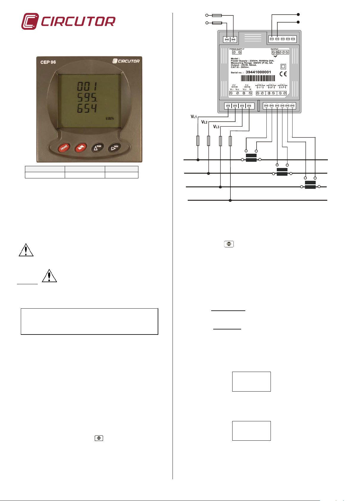
THREE-PHASE ENERGY
S1
P1
S2
P2
L1
L2
L3
N
S1
P1
S2
P2
S1
P1
S2
P2
N
CEP96
S2 S1 S2 S1 S2 S1
P2 P1 P2 P1 P2 P1
SET VOLT
027500
From 1 to 100000V
SET VOLT
SEC
Code
Type
Currents (Ib)
M3 0701
CEP-96 (ITF)
In / 5A
METER CEP 96
POWER SUPPLY
230V ac
Open collector
Common output
1.- MAIN FEATURES
Electronics-based, Class 1 rated, electrical energy meter, with 4
lines LCD display and also with bac klight, for its use in L.V. threephase networks, These energy meters are appropriate for any
application that requires the monitoring of partial energy
consumptions.
An additional open collector output can be used as a pulse output.
2.- Installation
This manual contains inf orm ation and warnings t hat m us t
be followed for operating the ENERGY METER safely and
maintaining the inst rument in a safe operating condi tion.
Whether the instrument is not used as manufacturer’s
specifications, the protection of the instrument can be damaged.
Mounting :
Instrument is t o be mounted on panel (cut-out 92
+0.8
x 92
per DIN 43 700). All connections k eep i nside the cabinet.
Note that with the instrum ent powered on, the term inals , cover
opening actions or elements removal may allow accessing
dangerous parts. The instrum ent must not be used until this is
completely instal l ed.
The monitored line should be provided with a c ircuit breaker or any
equivalent element (fuses) to disconnect the instrument from the
power supply network. This switching device m ust be placed near
the instrument and will be easi l y ac cessible.
The supply and measuring voltage circuits will be both connected
through a wire with a minimum c ros s-section of 1 m m
The line of the c urrent transformer secondary will have a mi nimum
cross-section of 2,5 m m
2
.
2
CEP-96 has a power supply input which is independent from the
measuring circuit.
Current measurement actions are done through external In / 5 A
current transformers.
3.- Screen
CEP 96 has two different screens which show the imported and
exported energy. By pressing the
imported energy (appears kW h on the fourth line) or the exported
energy (appears -kWh on the f ourt h l i ne).
key, you can choose the
.
+0.8
mm, as
... / 5 A current inputs are isolated.
4.- SETUP
(Simultaneously press the keys MAX and MIN when working in the
main program)
The key
validates the value and passes to the next
menu.
The key MAX permits the user to select among different
options in a menu or to increas e a digit when a variable is
being entered.
The key MIN is used to move t he cursor along the digits.
NOTE : When you arrive at t he last digit, you can move the position
of the decimal point with the "max" key.
When accessing SETUP, the following message in shown in screen
for some seconds:
(1) SETUP UNLOC (SETUP unlocked ) : when the
SETUP is accessed, configuration parameters can be
either visualized and modified.
(2) SETUP LOC (SE TUP locked ) : when the SETUP is
accessed, configurat ion parameters can be visualized but
cannot be modified .
Different options are following shown in a s equent i al mode:
4.1.- Voltage Transformer Primary
On the screen we read the word "SET VOLT PRI" f ol l owed by 6
digits. They allow us setti ng t he pri mary of the voltage transformer.
PRI
4.2.- Voltage Transformer Secon d ar y
We can now set the value of the secondary of the voltage
transformer. Only three digi t s are available:
001 From 1 to 999V
If the CEP-96 is directly connected t o the mains (without voltage
transformer) the values of pri mary and secondary must be t he same,
for instance 000001/001.
M98175401-03-13A
Page 2
4.3.- Current Transformer Primary
SET
CURR
PRI
000.900.1
SecV
imCurrPrimVPr
<
•
SET DISP
OFF
CLR
NO
OUT VAR
31 Active energy imported
CODE
45 Active energy generated
Parameter No
OUT 1
PULS
RATE
SET
Up
Unlo Loc (locked) or Unloc (unlocked)
Power supply : see specifications on th e rear par t o f the CV M-96
Operation temperature : -10 to 50 ºC
Measuring Circuits :
Rated voltage
300 V a.c. Phase-to-Neutral
520 V a.c. Phase-to-Phase
Rated current.
In / 5 A (isolated inputs)
Permanent overload.
Current input burden.
1.1 In
0.75 VA
Mechanical Characteristics :
Connection :
Weight
Pluggable connection terminal
0.4 kg
Length of pulse:
100 ms
Safety:
EN 61000-6-3, EN 61000-6-1, EN-61010-1
"SET A P" and five digit s appear on screen allowing us to set the
primary of the current transformer. The current green LEDs li ght on
to avoid mistakes .
00005
→From 1 A to 10.000 A
NOTE :
- The secondary of the current transformers is not programmable. It
is automaticall y set at 5 A (... / 5 A ac)
- The Voltages transformer and primary current value to be set is
also limited by the f ol l owing condi t i on:
- When trying to validate "
" a value exceeding the maximum
allowable value, the screen will blink and the previous value will be
saved.
4.4.- Setting preferred p ag e
This option allows the fixed or rotating pages ("SET def Page”):
- Fi xed page: selects Import or export screen, that will appear first
when applying voltage to the CEP 96 (or on resetti ng).
- Rot at i ng pages: automatical l y rot at es the pages (every 5 seconds
it moves on to the foll owing screen).
4.5.- Setting disconnection time for the backlight
Setting of the period of tim e t o go by, from t he m om ent that the CEP
keyboard is not touched anymore, before the CEP’s backlight is
automatically shut down (low consumption mode):
To exit this section press RESET (WARNING: in case of exit by
reset, latest m odification might not be saved) or go to the SETUP2
ending.
6.- MAINTENANCE
Before any adjustment, replacement, maintenance or repairing
operation is carried out, the instrum ent must be disconnect ed from
any power supply source.
When any protection failure is suspected to exist, the instrument
must be immediately put our of service. The instrument’s design
allows a quick replacement in case of any failure. In this case
contact a qualified service representative.
7.- Specifications
CEP-96
Single-phase 230 V a.c.
Voltage tolerance: -15 % / +10 %
Frequency: 50 ... 60 Hz
Burden : 4VA
Frequency 45 to 65 Hz
Minimum meas urabl e current.
1% In
Accuracy : 1 % of readout ± 2 digit s
Scale range measurement margin: 10 ..... 100 %
05
→ Time to shutdown (Minutes)
The backlight will be automat ically turned on, when any CEP key i s
pressed. If 00 is s et, the backlight is permanently on.
4.6.- Clearing energy counters
On display we see "CLR ENER no" (Clear energy counters).
ENER
4.7.- Relay Output.
This output is user settable to give a pulse every certain kW.h
(Energy). The value of consumed energy neces sary to generate an
output pulse can be defined (duration of t he pulse is 0.1 s): kW.h / 1
pulse.
On the CEP-96 screen following mes sages appear at this SETUP point:
31
Press the key
XXX.XXX
to validate the choice.
→
→ kW / pulse (1)
5.- SECOND SET-UP OF THE CEP-96
It is possible to access to a second MENU of SET-UP that
allows the configuration of the CEP -96 with other options different of
the standard ones. To enter into i t proceed as follows:
- Without power supply in the CEP-96, press simult aneously "
"max" and "min" keys.
- K eepi ng these keys pressed, supply the CEP-96.
We will read on the CEP-96 sc reen t he following:
SETUP lock and unlock
- If the LOC option is sel ected, when acc essing S ETUP jus t the
configuration can be check ed, but not modification is allowed.
- If the previously option is modified, a 4-digit password is
requested (if it is not c orrect, then the value blinks and the
previous menu is acces sed).
DEFAULT PASSWORD : 1234
Case material
Protection
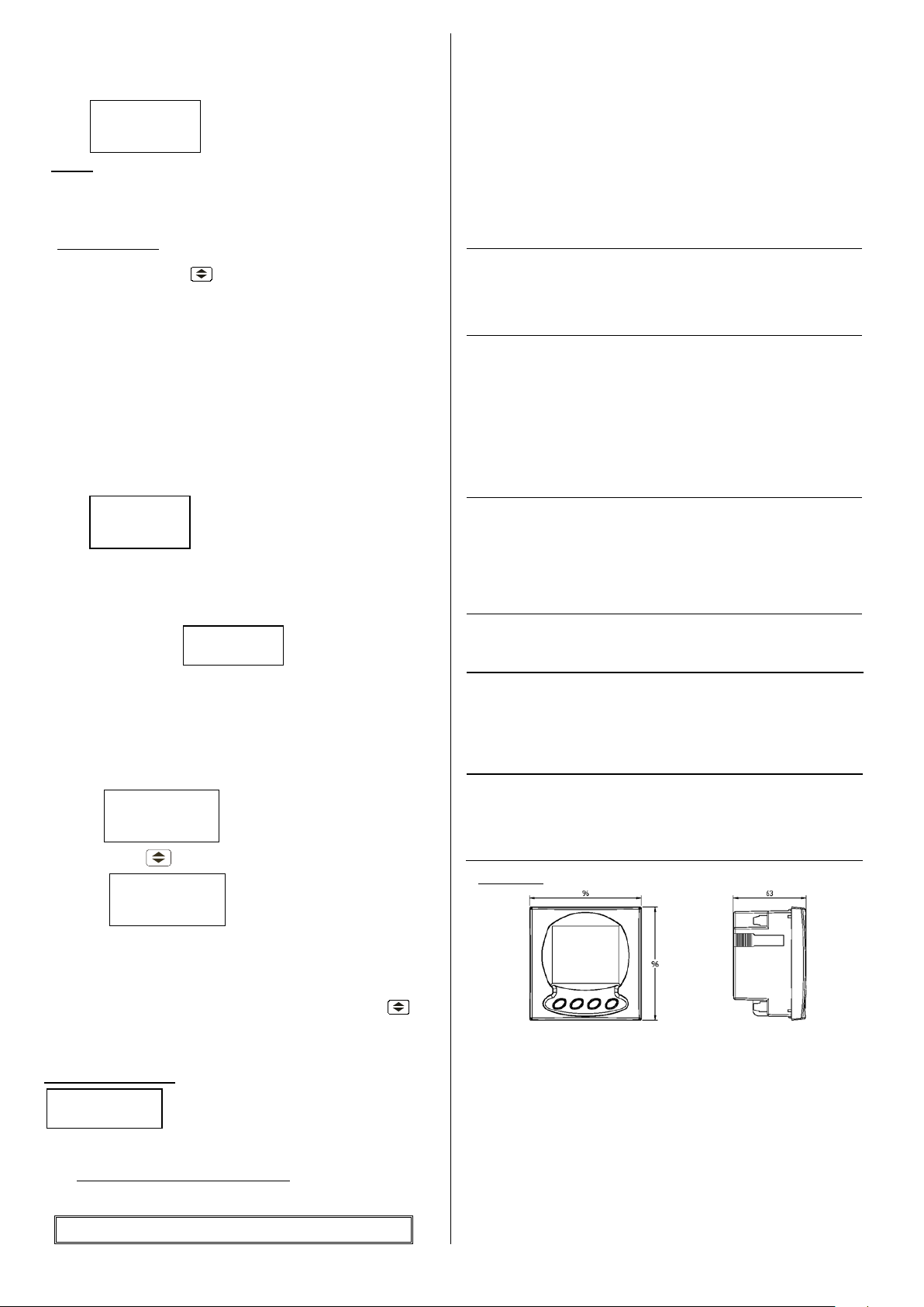
Dimensions
Metallic terminal with f l at headed screw.
Self-extinguishable, V0 plast i c
Assembled unit (f ront al ) : IP 51
Un-assembled unit (side and rear c overs ) : IP 31
96 x 96 mm - depth: 63 mm
Display:
-Type: LCD (4 lines) with backlight
-Energy unit : kW·h
-Maximum count: 999.999,999 kW·h
Transistor output features
Type: Opto-isolated transistor (open collector).
Maximum operating voltage:
Maximum operating current:
Maximum frequency:
Energy Output: (default)
NPN
24 V DC.
50 mA
5 pulses / second
100 pulses / kW.h
Category III - 300 V AC. / 520 AC. E N-61010 Class II double
insulation against electric shock
Standards :
IEC 664, VDE 0110, UL 94, IEC 801, IEC 348, IEC 571-1,
Dimensions :
",
8.- TECHNICAL SERVICE
In the event of any equipment failure or any operational queries
please contact the technical service of CIRCUTOR S. A .
CIRCUTOR S.A. - After sales service.
Vial Sant Jordi, s/n
08232 -Viladecavalls (Barcelona)
tel - (+34) 93 745 29 00 & fax - (+34) 93 745 29 14
E-mail : central @ circutor.es
M98175401-03-13A
 Loading...