

Page 1

INSTRUCTION MANUAL
(M187B01-03-18A)
Multifunctional Energy Meter
CEM-C6
Page 2

2
CEM-C6
Instruction Manual
Page 3
SAFETY PRECAUTIONS
DISCLAIMER
CIRCUTOR, SA reserves the right to make modi cations to the device or the unit speci ca-
tions set out in this instruction manual without prior notice.
CIRCUTOR, SA on its web site, supplies its customers with the latest versions of the device
speci cations and the most updated manuals.
www.circutor.com
CIRCUTOR, recommends using the original cables and accessories that are
supplied with the device.
DANGER
Warns of a risk, which could result in personal injury or material damage.
ATTENTION
Indicates that special attention should be paid to a speci c point.
Follow the warnings described in this manual with the symbols shown below.
If you must handle the unit for its installation, start-up or maintenance, the following
should be taken into consideration:
Incorrect handling or installation of the unit may result in injury to personnel as well as damage
to the unit. In particular, handling with voltages applied may result in electric shock, which may
cause death or serious injury to personnel. Defective installation or maintenance may also
lead to the risk of re.
Read the manual carefully prior to connecting the unit. Follow all installation and maintenance
instructions throughout the unit’s working life. Pay special attention to the installation standards of the National Electrical Code.
Refer to the instruction manual before using the unit
In this manual, if the instructions marked with this symbol are not respected or carried out correctly, it can
result in injury or damage to the unit and /or installations.
CIRCUTOR, SA reserves the right to modify features or the product manual without prior noti cation.
3
Instruction Manual
CEM-C6
Page 4

CONTENTS
SAFETY PRECAUTIONS ���������������������������������������������������������������������������������������������������������������������������������������3
DISCLAIMER ���������������������������������������������������������������������������������������������������������������������������������������������������������� 3
CONTENTS ������������������������������������������������������������������������������������������������������������������������������������������������������������� 4
REVISION LOG �������������������������������������������������������������������������������������������������������������������������������������������������������5
SYMBOLS ��������������������������������������������������������������������������������������������������������������������������������������������������������������� 5
1�- VERIFICATION UPON RECEPTION ����������������������������������������������������������������������������������������������������������������� 6
2�- PRODUCT DESCRIPTION �������������������������������������������������������������������������������������������������������������������������������� 6
3�- DEVICE INSTALLATION ����������������������������������������������������������������������������������������������������������������������������������� 7
3�1�- PRELIMINARY RECOMMENDATIONS �����������������������������������������������������������������������������������������������������7
3�2�- INSTALLATION ������������������������������������������������������������������������������������������������������������������������������������������8
3�3�- DEVICE TERMINALS ��������������������������������������������������������������������������������������������������������������������������������� 9
3�4�- CONNECTION DIAGRAM �������������������������������������������������������������������������������������������������������������������������� 9
4�- OPERATION ��������������������������������������������������������������������������������������������������������������������������������������������������� 10
4�1�- KEYBOARD FUNCTIONS ����������������������������������������������������������������������������������������������������������������������� 10
4�2�- DISPLAY �������������������������������������������������������������������������������������������������������������������������������������������������� 10
4�3�- LED INDICATORS ����������������������������������������������������������������������������������������������������������������������������������� 10
5�- DISPLAY ��������������������������������������������������������������������������������������������������������������������������������������������������������� 11
6�- RS-485 COMMUNICATIONS ��������������������������������������������������������������������������������������������������������������������������� 12
6�1�- MODBUS PROTOCOL ����������������������������������������������������������������������������������������������������������������������������12
6�1�1� READING EXAMPLE : Function 0x03� ������������������������������������������������������������������������������������������� 12
6�2�- MODBUS COMMANDS ����������������������������������������������������������������������������������������������������������������������������13
7�- TECHNICAL FEATURES �������������������������������������������������������������������������������������������������������������������������������� 15
8�- MAINTENANCE AND TECHNICAL SERVICE ������������������������������������������������������������������������������������������������ 17
9�- GUARANTEE ���������������������������������������������������������������������������������������������������������������������������������������������������17
10�- CE CERTIFICATE ������������������������������������������������������������������������������������������������������������������������������������������ 18
Note: The images of the devices are solely for the purpose of illustration and may differ from
the original device.
4
CEM-C6
Instruction Manual
Page 5
REVISION LOG
Table 1: Revision log�
Date Revision Description
12/17 M187B01-03-17A Initial Version
04/18 M187B01-03-17A
Changes in the following sections:
3.2. - 6.- 7.
SYMBOLS
Table 2: Symbols�
Symbol Description
In compliance with the relevant European directive.
Device covered by European directive 2012/19/EC. At the end of its useful life, do not
leave the unit in a household waste container. Follow local regulations
on electronic equipment recycling.
~
AC current
5
Instruction Manual
CEM-C6
Page 6
1�- VERIFICATION UPON RECEPTION
Check the following points upon receiving the device:
a) The device meets the specications described in your order.
b) The device has not suffered any damage during transport.
c) Perform an external visual inspection of the unit prior to switching it on.
d) Check that it has been delivered with the following:
- An installation guide,
If any problem is noticed upon reception, immediately contact the transport
company and/or CIRCUTOR's after-sales service.
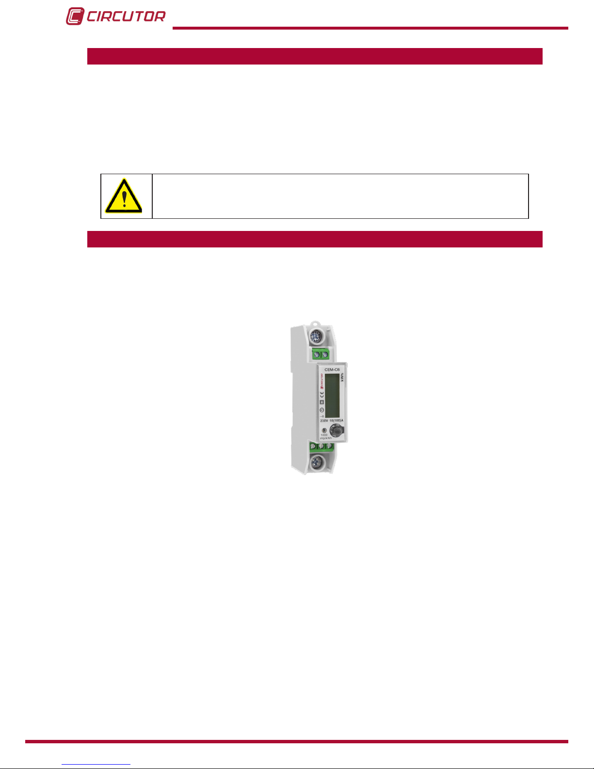
2�- PRODUCT DESCRIPTION
The CEM-C6 static single-phase energy meter measures class 1, with multifunction, RS-485
communications and DIN rail standard installations. It is the ideal solution for residential and
commercial installations.
The device features:
- The meter can read these data during the denite time period and analysis the quality
and load condition of user’s grid.
- DIN rail standard installation size.
- Only 18 mm wide, can up to 100A.
- RS-485 communication, protocol: IEC1107 or Modbus-TRU Mode.
- Multi-tariff function� The user can set time period through RS-485 communication,
then the meter will measure the energy of each different time period.
- Meter has 3.6V Lithium battery, which is used to support multy-tariff function. And the
precision of RTC is better that 0.5s/day.
- Blue LCD backlight allows the meter to be read in low light conditions.
- Accurately measure fordward and reverse energy.
6
CEM-C6
Instruction Manual
Page 7
3�- DEVICE INSTALLATION
3.1.- PRELIMINARY RECOMMENDATIONS
In order to use the device safely, it is critical that individuals who handle it follow
the safety measures set out in the standards of the country where it is being used,
use the necessary personal protective equipment, and pay attention to the various warnings indicated in this instruction manual.
The CEM-C6 device must be installed by authorised and qualied staff.
The measuring systems switched off before handling, altering the connections or replacing the
device. It is dangerous to handle the unit while it is powered.
Also, it is critical to keep the cables in perfect condition in order to avoid accidents, personal
injury and damage to installations.
The manufacturer of the device is not responsible for any damage resulting from failure by the
user or installer to observe the warnings and/or recommendations set out in this manual, nor for
damage resulting from the use of non-original products or accessories or those made by other
manufacturers.
If an anomaly or malfunction is detected in the device, do not use the device to take any measurements.
Inspect the work area before taking any measurements. Do not take measurements in dangerous areas or where there is a risk of explosion.
Disconnect the device from the power supply before maintaining, repairing or
handling the device's connections.
Please contact the after-sales service if you suspect that there is an operational
fault in the device.
7
Instruction Manual
CEM-C6
Page 8

3.2.- INSTALLATION
Terminals, opening covers or removing elements can expose parts that are hazardous to the touch while the device is powered. Do not use the device until it is
fully installed.
Installation instruction:
1�- Choose 35mm standard DIN rail (the length is conrmed by yourself), xed them in the
location which are waiting for installation.
2�- Push down the clip under the bottom of the meter for a gear, see Figure 1�
After push down
the clip
Después de
empujar hacia
abajo el clip
Figure 1:Push down the clip�
3�- Put the meter into the DIN rail as per Figure 2, then push up the clip for a gear, install
meter to the DIN rail, see Figure 3.
Figure 2:Put the meter into the DIN rail� Figure 3: Install meter to the DIN rail�
4�- Making the connection according to the wiring diagram.
5�- After connection, use lead sealing to seal terminal cover.
8
CEM-C6
Instruction Manual
Page 9

3.3.- DEVICE TERMINALS
Table 3:List of CEM-C6 terminals�
Device terminals
1 : L, Input, connected to the mains phase 23: A, RS-485 connection
3: LOAD, Output 24: G, RS-485 connection
N: N, Input, connected to neutral 25: B, RS-485 connection
1N
N
3 25 24
23
Figure 4:Terminals of the CEM-C6�
Note: The Neutral wire can be connected to one of N ports or borh.
Note: If RS-485 transverter does not have G port, it’s Ok to disconnect it.
3.4.- CONNECTION DIAGRAM
L
IN
N
LOAD
OUT
Figure 5: Connection diagram, CEM-C6�
9
Instruction Manual
CEM-C6
Page 10

4�- OPERATION
The CEM-C6 is an energy meter capable of measuring:
Voltage and current
Active, reactive and apparent power.
Power factor, PF
4.1.- KEYBOARD FUNCTIONS
The CEM-C6 has 1 key that allows you to browse the different screens (Figure 6).
Keyboard
Display
LED
Figure 6: CEM-C6, description�
4.2.- DISPLAY
The device has an LCD where all parameters are displayed (Figure 6).
4.3.- LED INDICATORS
The device has one verication LED, to verify the active energy� The weight of the LED is 1000
imp/kWh (Figure 6).
10
CEM-C6
Instruction Manual
Page 11

5�- DISPLAY
The data can be displayed through 2 methods:
Display data automatically by page and the time interval is 5s.
Check data through the external key.
Table 4: Display�
Screen Parameters
kWh
Partial active Energy counter (kWh)
V
Voltage (V)
A
Current (A)
kW
Active power (kW)
kVAr
Reactive power (kVAr)
kVA
Apparent power (kVA)
Power factor (cos ɸ)
11
Instruction Manual
CEM-C6
Page 12

6�- RS-485 COMMUNICATIONS
The CEM-C6 devices has one RS-485 communications port. The device has the MODBUS
RTU communication protocol as standard.
6.1.- MODBUS PROTOCOL
In the Modbus protocol, the CEM-C6 device uses the RTU (Remote Terminal Unit) mode.
The Modbus functions implemented in the device are as follows:
Function 0x03: Reading integer registers
Function 0x10: Writing multiple registers
6�1�1� READING EXAMPLE : Function 0x03�
Question: Voltage value
Address Function
Initial
register
No� of
registers
CRC
01 03 0000 0001 840A
Address: 01, Peripheral number: 1 in decimals.
Function: 03, Read function.
Initial Register: 0000, register on which the reading will start. (Modbus address).
No of registers: 0001, number of registers read.
CRC: 840A, CRC Character.
Response:
Address Function
No of
Bytes
Register
no 1
CRC
01 03 02 091F FFDC
Address: 01, Responding peripheral number: 10 in decimals.
Function: 03, Read function.
No� of bytes: 02, No. of bytes received.
Register: 091F, value of the voltage :091F : 2335 ; : 233.5V
CRC: FFDC, CRC Character.
12
CEM-C6
Instruction Manual
Page 13

6.2.- MODBUS COMMANDS
All the adresses of Modbus memory are in Hexadecimal.
Table 5: Modbus memory map (Table 1)�
Parameter
Modbus
address
Function Units
Voltage 00 03 V x 10
Current 01 03 A x 10
Frequency 02 03 Hz x 10
Active Power 03 03 W
Reactive Power 04 03 var
Apparent Power 05 03 VA
Power Factor 06 03 x 100
Table 6: Modbus memory map (Table 2)�
Parameter
Modbus
address
Function Data format
(1)
Units
Active energy 07 ... 10 03 / 10 AA AA BB BB CC CC DD DD EE EE Wh x 10
reactive energy 11 ... 1A 03 / 10 AA AA BB BB CC CC DD DD EE EE Varh x 10
(1)
Data format :
Table 7: Data format�
Data format Description
AA AA Total Active/Reactive energy
BB BB Tariff 1 Active/Reactive energy
CC CC Tariff 2 Active/Reactive energy
DD DD Tariff 3 Active/Reactive energy
EE EE Tariff 4 Active/Reactive energy
Table 8: Modbus memory map (Table 3)�
Parameter
Modbus
address
Function Data format
(2)
Tme table (by tariff) 1B ... 20 03 / 10 HM 1H M2 HM 3H M4
Date and time 21 ... 1A 03 / 10 YY YY MM DD WW hh mm ss
(2)
Data format :
Table 9: Data format�
Parameter Data format Description
Tme table
(by tariff)
HM1 Hours, Minutes ,Tariff 1
HM2 Hours, Minutes ,Tariff 2
HM3 Hours, Minutes ,Tariff 3
HM4 Hours, Minutes ,Tariff 4
13
Instruction Manual
CEM-C6
Page 14

Table 9 (Continuation): Data format�
Parameter Data format Description
Date and time
YY YY Year
MM Month
DD Day
WW Week
hh Hour
mm Minutes
ss Seconds
Table 10: Modbus memory map (Table 4)�
Parameter
Modbus
address
Function
Serial number 27 ... 29 03 / 10
ID (peripheral number) 2B 03 / 10
Table 11: Modbus memory map (Table 5)�
Parameter
Modbus
address
Function Data format
Baud Rate 2A 03 / 10
01: 1200 bps, 02: 2400 bps
03: 4800 bps, 04: 9600 bps
14
CEM-C6
Instruction Manual
Page 15

7�- TECHNICAL FEATURES
Power supply
Mode Self-powered
Voltage Measurement
Connection Single-phase
Reference voltages 230 V ~
Frequency 50 - 60Hz
Power consumption ≤ 8 VA, ≤ 0.4 Wh
Current measurement
Current 10 A
Maximum current (Imax) 100 A
Starting current 0.004 Ib
Accuracy
Accuracy Class 1
RS-485 Communications
Bus RS-485
Protocol Modbus RTU
Baud rate 1200 - 2400 - 4800 - 9600
User interface
Display LCD
Maximum counter value 99999.9 kWh
Keys 1 keys
LED (kWh) 1000 imp/kWh ( width: 90 ms)
Environmental features
Operating temperature -20ºC... +65ºC
Relative humidity (maximum value) 95%
Average humidity value of year 75%
Mechanical features
Dimensions ( Figure 7) 90x18x72 mm
Weight 0.10 kg
Enclosure ABS, PC alloy material
Protection degree IP 51 (indoor meter)
Connections
(maximum)
RS-485 (A, G, B) 1.5 mm
2
Neutral (N) 1.5 mm
2
Measure (L, LOAD) 22 mm
2
Standards
Electrical energy metering equipment (AC)� Particular requirements�
Part 21: Static active energy meters (classes 1 and 2)
IEC 62053-21:2003
Electricity metering equipment (AC) - General requirements, tests and
test conditions -- Part 11: Metering equipment
IEC 62052-11:2003
15
Instruction Manual
CEM-C6
Page 16

47.8
4
72
459036
18
Figure 7: Dimensions of the CEM-C6�
16
CEM-C6
Instruction Manual
Page 17

8�- MAINTENANCE AND TECHNICAL SERVICE
9�- GUARANTEE
• No returns will be accepted and no unit will be repaired or replaced if it is not ac-
companied by a report indicating the defect detected or the reason for the return.
•The guarantee will be void if the units has been improperly used or the storage, installation and maintenance instructions listed in this manual have not been
followed. “Improper usage” is de ned as any operating or storage condition contrary to the national electrical code or that surpasses the limits indicated in the
technical and environmental features of this manual.
• CIRCUTOR accepts no liability due to the possible damage to the unit or other
parts of the installation, nor will it cover any possible sanctions derived from a possible failure, improper installation or “improper usage” of the unit. Consequently,
this guarantee does not apply to failures occurring in the following cases:
- Overvoltages and/or electrical disturbances in the supply;
- Water, if the product does not have the appropriate IP classi cation;
- Poor ventilation and/or excessive temperatures;
- Improper installation and/or lack of maintenance;
- Buyer repairs or modi cations without the manufacturer’s authorisation.
CIRCUTOR guarantees its products against any manufacturing defect for two years after the
delivery of the units.
CIRCUTOR will repair or replace any defective factory product returned during the guarantee
period.
In the case of any query in relation to device operation or malfunction, please contact the
CIRCUTOR, SA Technical Support Service.
Technical Assistance Service
Vial Sant Jordi, s/n, 08232 - Viladecavalls (Barcelona)
Tel: 902 449 459 ( España) / +34 937 452 919 (outside of Spain)
email: sat@circutor.com
17
Instruction Manual
CEM-C6
Page 18

10�- CE CERTIFICATE
18
CEM-C6
Instruction Manual
Page 19

19
Instruction Manual
CEM-C6
Page 20

20
CEM-C6
Instruction Manual
Page 21

21
Instruction Manual
CEM-C6
Page 22

CIRCUTOR, SA
Vial Sant Jordi, s/n
08232 -Viladecavalls (Barcelona)
Tel.: (+34) 93 745 29 00 - Fax: (+34) 93 745 29 14
www.circutor.com central@circutor.com
 Loading...