

cincinnati CL-900 Maintenance Manual
OPERATION, SAFETY, AND MAINTENANCE MANUAL
CINCINNATIR
cl-900 SERIES lASER SYSTEM
(IPG FIBER LASER RESONATORS - 5x10, 6x12 FRAME)
CINCINNATI INCORPORATED
CINCINNATIR
EM-550 (N-04/11) COPYRIGHT 2011
C I N C I N N A T I, OHIO 4 5 2 1 1
CINCINNATI INCORPORATED


cl-900 SERIES cONTENTS
INTRODUCTION
SECTION 1 IDENTIFICATION
SECTION 2 INSTALLATION
LIFTING AND MOVING ..................................................................................2-1
FOUNDATION ................................................................................................ 2-2
INSTALLATION OF MACHINE .......................................................................2-2
CHILLER ........................................................................................................2-2
LEVELING ......................................................................................................2-2
PRELIMINARY LEVELING .......................................................................2-3
FINAL LEVELING .....................................................................................2-3
ELECTRICAL CONNECTION ........................................................................ 2-5
SAFETY DEVICES ......................................................................................... 2-5
SECTION 3 SAFETY
SAFETY IS EVERYONE’S JOB .....................................................................3-1
INTRODUCTION TO LASER SAFETY ....................................................3-1
SAFETY STANDARDS AND PUBLICATIONS ...............................................3-2
LASER HAZARD CLASSIFICATION .............................................................3-2
CONTROL MEASURES ................................................................................. 3-3
EXPLANATION OF LASER RADIATION........................................................3-4
LASER TYPES .........................................................................................3-4
HAZARDS - CINCINNATI LASER SYSTEMS - FIBER LASER .....................3-5
EYE HAZARDS ........................................................................................3-5
SKIN HAZARDS .......................................................................................3-5
NOMINAL HAZARD ZONES ..........................................................................3-6
BEAM EXPOSURE CATEGORIES ..........................................................3-6
ASSOCIATED HAZARDS .............................................................................. 3-7
FIRE .........................................................................................................3-7
FUMES AND DUST ..................................................................................3-8
GAS STORAGE .............................................................................................3-8
COMPRESSED GAS CYLINDERS ..........................................................3-8
CRYOGENIC LIQUID .............................................................................3-10
TRAINING ....................................................................................................3-11
MACHINE HAZARDS AND WARNINGS ...................................................... 3-11
MOVING MACHINE MEMBERS ............................................................ 3-11
WARNING (AWARENESS) LIGHTS ......................................................3-11
CUT AREA SAFETY ENCLOSURE ....................................................... 3-11
SAFETY SIGNS ...........................................................................................3-12
SAFETY GUIDELINES ................................................................................. 3-14
SAFETY MAINTENANCE CHECK ............................................................... 3-14
SECTION 4 SPECIFICATIONS
DIMENSIONS ................................................................................................. 4-1
SPECIFICATIONS ..........................................................................................4-1
PIPING CONNECTIONS ................................................................................ 4-2
EXTERNAL OPTICAL ELEMENTS ................................................................ 4-3
GAS REQUIREMENTS ..................................................................................4-3
AMBIENT TEMPERATURE ............................................................................4-5
CAPACITIES .................................................................................................. 4-5
PRINCIPLE OF OPERATION .........................................................................4-6
CONTOURING ACCURACY ..........................................................................4-6
SECTION 5 SETUP AND USE
LOADING MATERIAL .....................................................................................5-1
GAUGING .......................................................................................................5-1
CUTTING Y-AXIS MATERIAL STOPS .....................................................5-1
X AND Y-AXIS SQUARENESS ................................................................5-2
X-AXIS MATERIAL STOPS ......................................................................5-3
EM-550 (N-04/11)

SECTION 6 MACHINE CONTROLS
OPERATOR CONTROL STATION .................................................................6-1
MACHINE OPERATOR PANELS ................................................................... 6-2
FRONT PANEL CONTROLS ....................................................................6-2
SIDE PANEL CONTROLS ........................................................................6-4
LOAD FRAME EMERGENCY STOP ............................................................. 6-6
SECTION 7 OPERATION
FOR ADDITIONAL SETUP AND OPERATION INFORMATION FOR THIS
MACHINE, REFER TO EM-551, SECTION 7 - OPERATION, A SUPPLEMENT TO
THE OPERATION MANUAL FOR THE CL-900 LASER SYSTEM. ...............7-1
SECTION 8 OPTIONS
FUME BLOWER ............................................................................................. 8-1
BALL TRANSFER LOAD STATION ................................................................8-1
MODULAR MATERIAL HANDLING SYSTEM (MMHS) .................................8-1
AIR ASSIST GAS FILTER AND DRYER ........................................................ 8-1
SECTION 9 MAINTENANCE AND ADJUSTMENTS
LUBRICATION REQUIREMENTS ..................................................................9-1
DRIVES LUBRICATION ...........................................................................9-1
Z-AXIS LUBRICATION .............................................................................9-1
FUME SYSTEM LUBRICATION ...............................................................9-2
MATERIAL CLAMP LUBRICATION ..........................................................9-2
MAGNETIC TRACK MAINTENANCE ............................................................ 9-2
PALLET DRIVE MAINTENANCE ...................................................................9-2
GEAR REDUCER.....................................................................................9-2
CHAIN DRIVE TENSION ADJUSTMENT ............................................... 9-2
SCRAP REMOVAL ...................................................................................9-3
PALLET GUIDE RAILS ...................................................................................9-3
ENCODER MAINTENANCE ..........................................................................9-3
ENCODER CLEANING ............................................................................9-4
OPTICS HANDLING AND CLEANING ...........................................................9-4
LENS INSTALLATION AND REMOVAL ...................................................9-5
LENS CLEANING .....................................................................................9-5
AUTO FOCUS CUTTING HEAD ....................................................................9-6
MAINTENANCE .......................................................................................9-6
AUTO FOCUS TROUBLESHOOTING ..................................................... 9-7
AIR DRYER ....................................................................................................9-8
PREVENTIVE MAINTENANCE ....................................................................9-10
DAILY MACHINE INSPECTION .............................................................9-10
WEEKLY MACHINE INSPECTION .......................................................9-10
SEMI-ANNUAL (1000 HOURS) MACHINE INSPECTION .....................9-10
ANNUAL MACHINE INSPECTION ........................................................9-11
EM-550 (N-04/11)
SECTION 10 SERVICE AND PARTS
ORDERING REPAIR PARTS ......................................................................10-1
RETURNING PARTS FOR CREDIT ............................................................. 10-1
SERVICE ...................................................................................................... 10-1
TECHNICAL TRAINING ...............................................................................10-1
CUSTOMER INFORMATION CENTER .......................................................10-1

INTRODUCTION
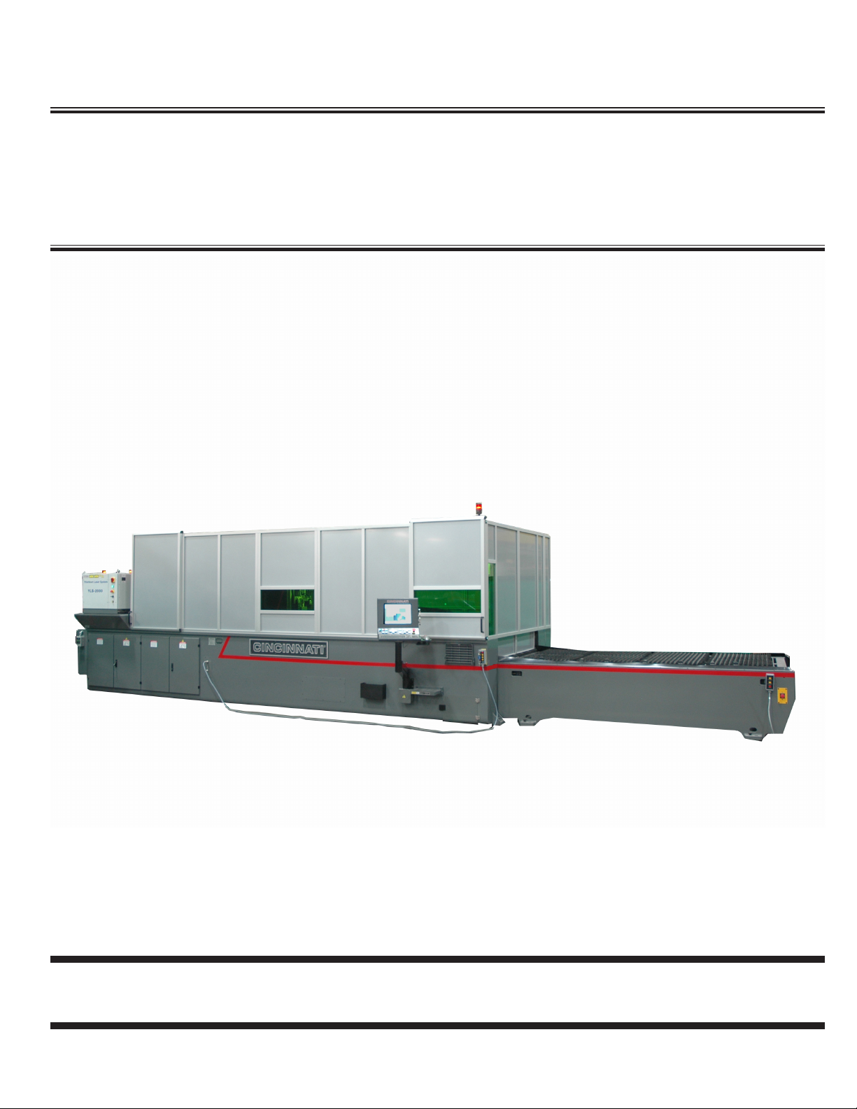
CINCINNATI CL-900 SERIES LASER SYSTEM - FIBER LASER
The Fiber Laser System produces two-dimensional contoured shapes from at material by moving a focused
laser beam along a programmed path. The beam from a stationary laser generating unit is directed to a
moving lens by a ber optic cable routed through a moving gantry. The workpiece remains stationary while
a narrow strip of material is removed along the path made by the lens. Material is removed by vaporization
and melting where the lens concentrates laser power into a small spot on the workpiece. Assist gas is also
used to control the cutting process.
The gantry moves the lens to produce the programmed workpiece geometry. A motion controller commands
servo drives to control the gantry motion. The program provided by the user includes commands to specify
feed rate, laser power, and assist gas.
PART QUALITY
The following factors affect part quality:
Machine condition•
Operator ability•
Setup and Programming•
Quality and type of material•
CINCINNATI machines are designed to be rugged and durable. However, improper adjustment or lack
of maintenance can reduce the quality of parts produced on the machine. The quality of a laser-cut
edge depends on the combination of a uniform laser beam of adequate power, properly focused on the
workpiece with an adequate supply of the correct assist gas, traveling at a speed compatible with the
material removal rate.
Critical manual adjustments are: lens focal point location and lens-to-nozzle centering. The Auto Focus
Cutting Head eliminates manual focal point adjustment.
Part quality depends on the program to command the correct combination of laser power, assist gas, and
feedrate for the material type and thickness being processed. Part accuracy depends on the program for
proper use of kerf width compensation and for selection of feedrate within radius contouring accuracy
limits.
Material quality can affect the repeatability of process parameters. Material with uniform composition,
uniform thickness, and a smooth, clean surface will minimize variations in part quality.

EM-550 (N-04/11)
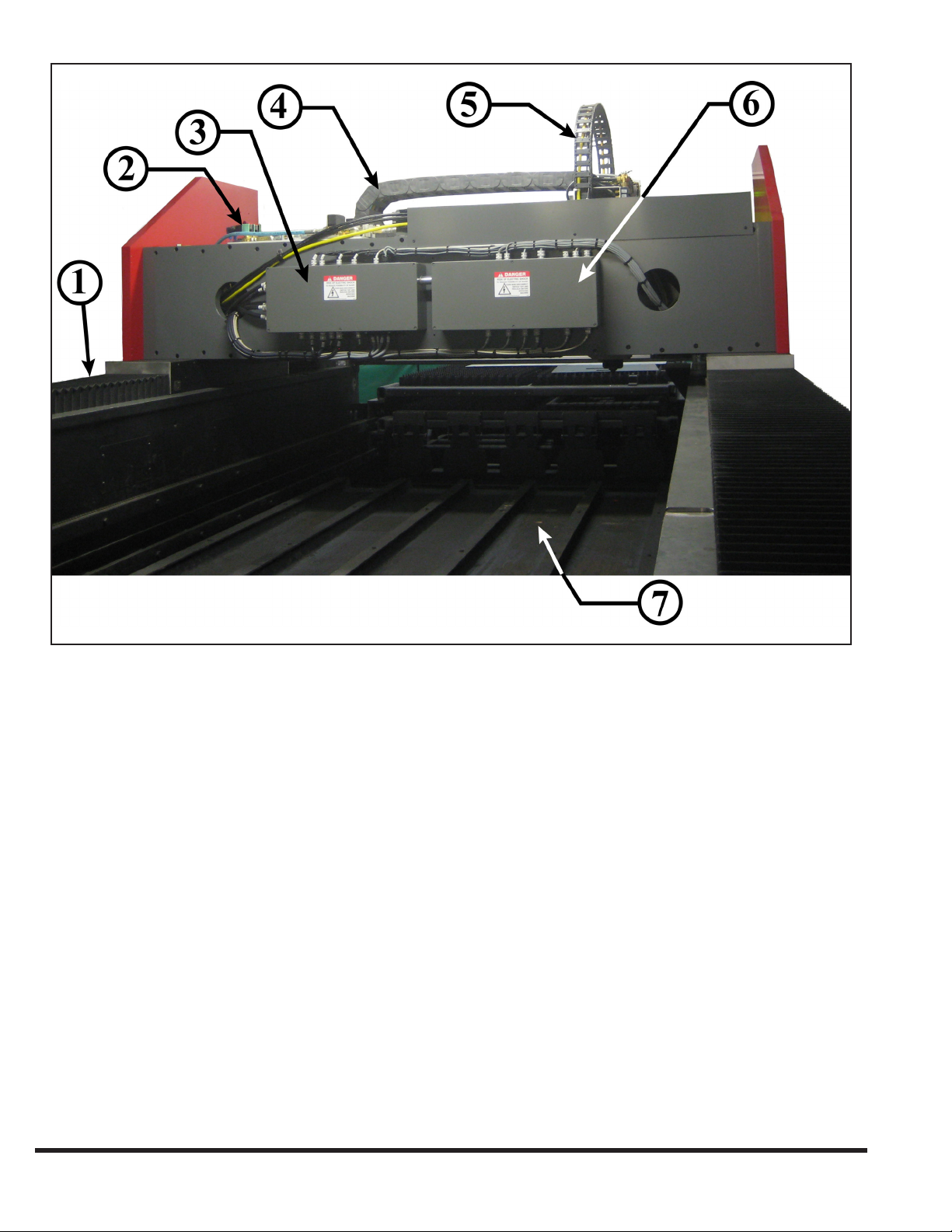
SEcTION 1 IDENTIFIcATION
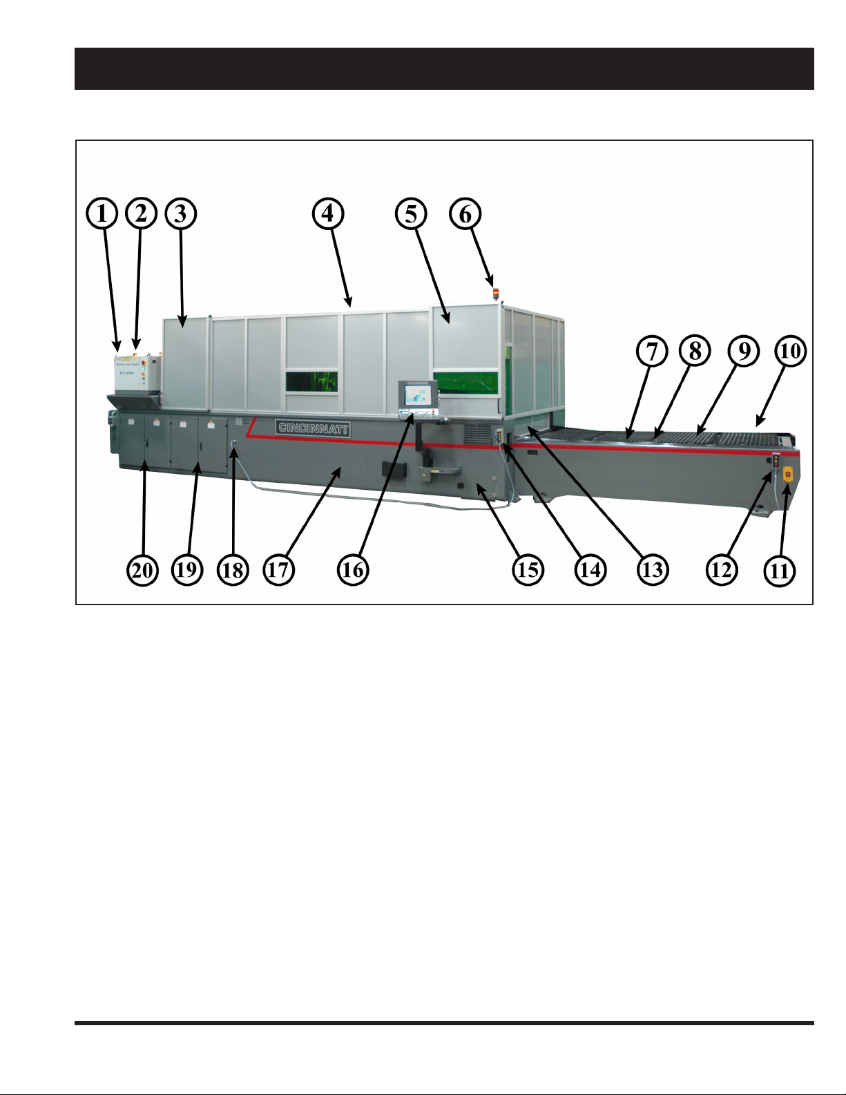
CINCINNATI CL-900 SERIES LASER SYSTEM - FIBER LASER
FIBER LASER1.
LASER STATUS INDICATOR LIGHT 2.
SERVICE SAFETY DOOR3.
SAFETY ENCLOSURE 4.
OPERATOR SAFETY DOOR 5.
LASER STATUS INDICATOR LIGHT6.
MATERIAL SUPPORTS7.
MATERIAL CLAMPS8.
LOWER PALLET9.
LOAD FRAME10.
Figure 1-1 Front View
1-1
E-STOP BUTTON11.
BALL TRANSFER REMOTE (OPT)12.
PALLET DOOR13.
REMOTE STATION14.
SCRAP BIN ACCESS DOOR15.
OPERATOR CONTROL STATION16.
MAIN FRAME17.
REMOTE STATION CONNECTION18.
CONTROL ENCLOSURE19.
POWER ENCLOSURE20.
EM-550 (N-04/11)
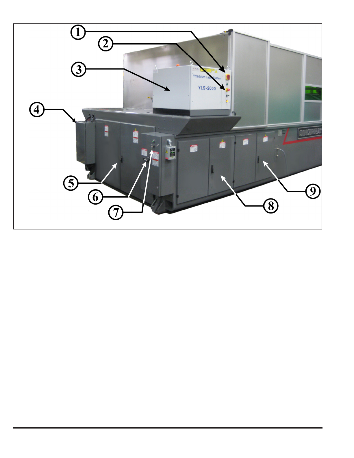
FIBER LASER MAIN DISCONNECT1.
FIBER LASER E-STOP2.
FIBER LASER GAS AND COOLANT CONNECTION3.
MAIN ENCLOSURE 4.
MAIN DISCONNECT 5.
Figure 1-2 Rear View
MAIN BREAKER INTERLOCK BYPASS KEY6.
POWER ENCLOSURE7.
CONTROL ENCLOSURE8.
EM-550 (N-04/11)
1-2
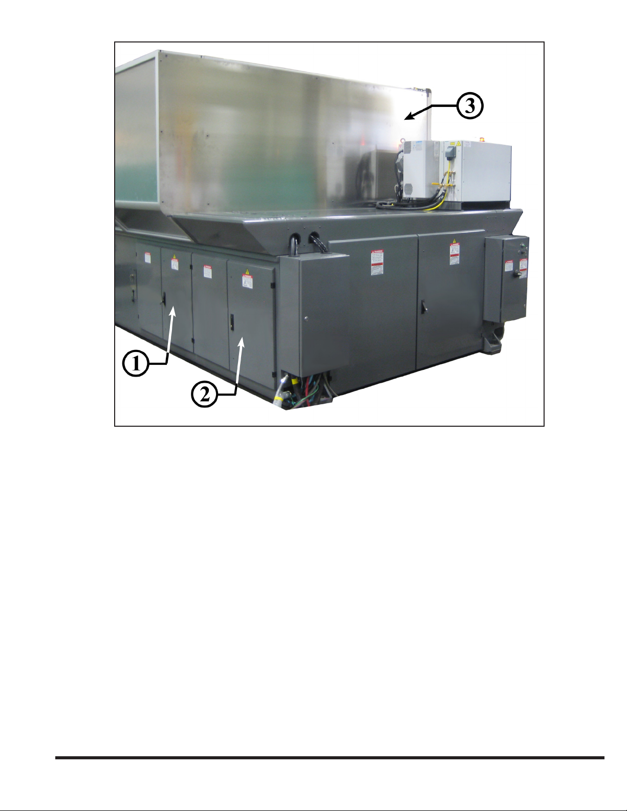
I/O ENCLOSURE1. DRIVE ENCLOSURE2. SAFETY ENCLOSURE3.
Figure 1-3 Rear View
1-3
EM-550 (N-04/11)
X-2 AXIS WAY COVER1.
ASSIST GAS PROPORTIONAL VALVES 2.
LEFT GANTRY ENCLOSURE3.
Y-AXIS CABLE CARRIER 4.
Figure 1-4 Rear View of the Gantry
Z-AXIS FIBER CABLE CARRIER5.
RIGHT GANTRY ENCLOSURE 6.
SCRAP TRAYS AND SCRAP TRAY CAPS7.
EM-550 (N-04/11)
1-4
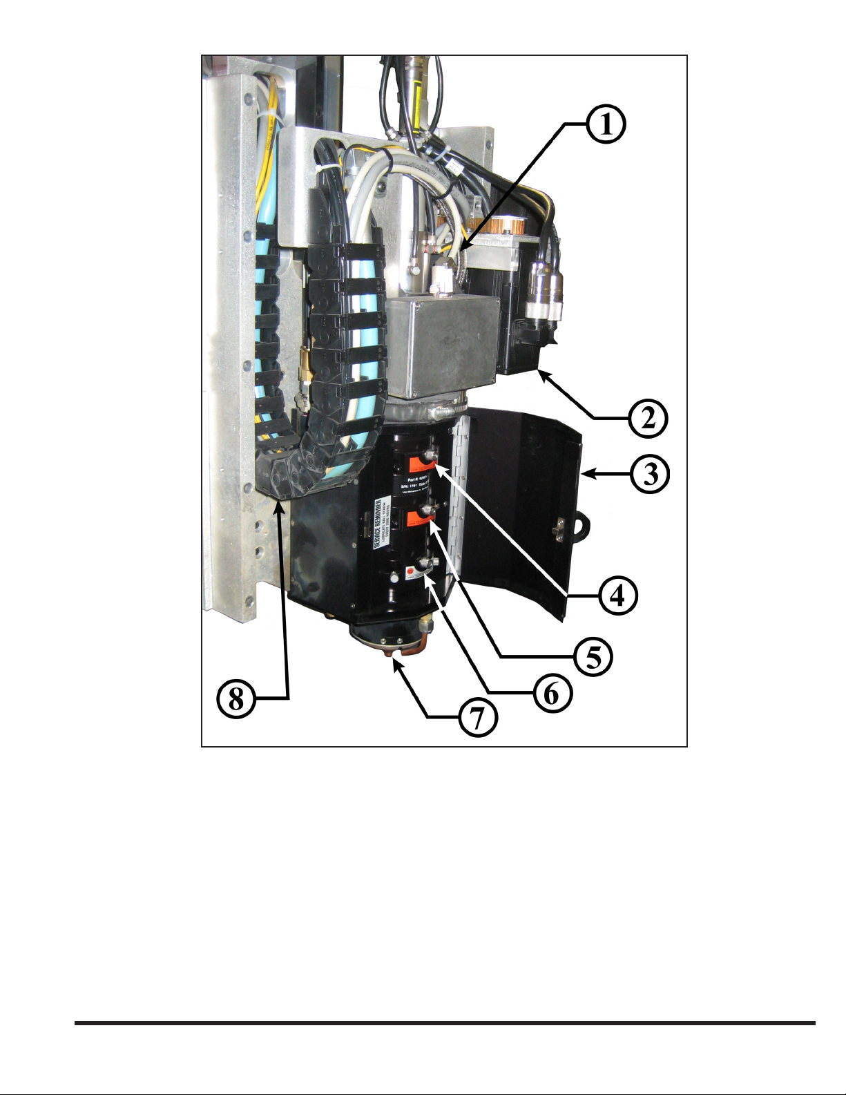
ASSIST GAS HOSE1.
Z-AXIS MOTOR 2.
LENS DOOR 3.
10 INCH LENS DRAWER (EMPTY MANIFOLD SEAL) 4.
Figure 1-5 Y-Plate and Auto Focus Head Assembly
7.5 INCH LENS DRAWER (EMPTY MANIFOLD SEAL) 5.
5 INCH LENS DRAWER (INSTALLED) 6.
LOWER TIP ASSEMBLY 7.
Z-AXIS CABLE CARRIER8.
1-5
EM-550 (N-04/11)

EM-550 (N-04/11)
1-6
SEcTION 2 INSTAllATION
IMPORTANT: Before proceeding, contact CINCINNATI
Laser Service for pre-installation instructions.
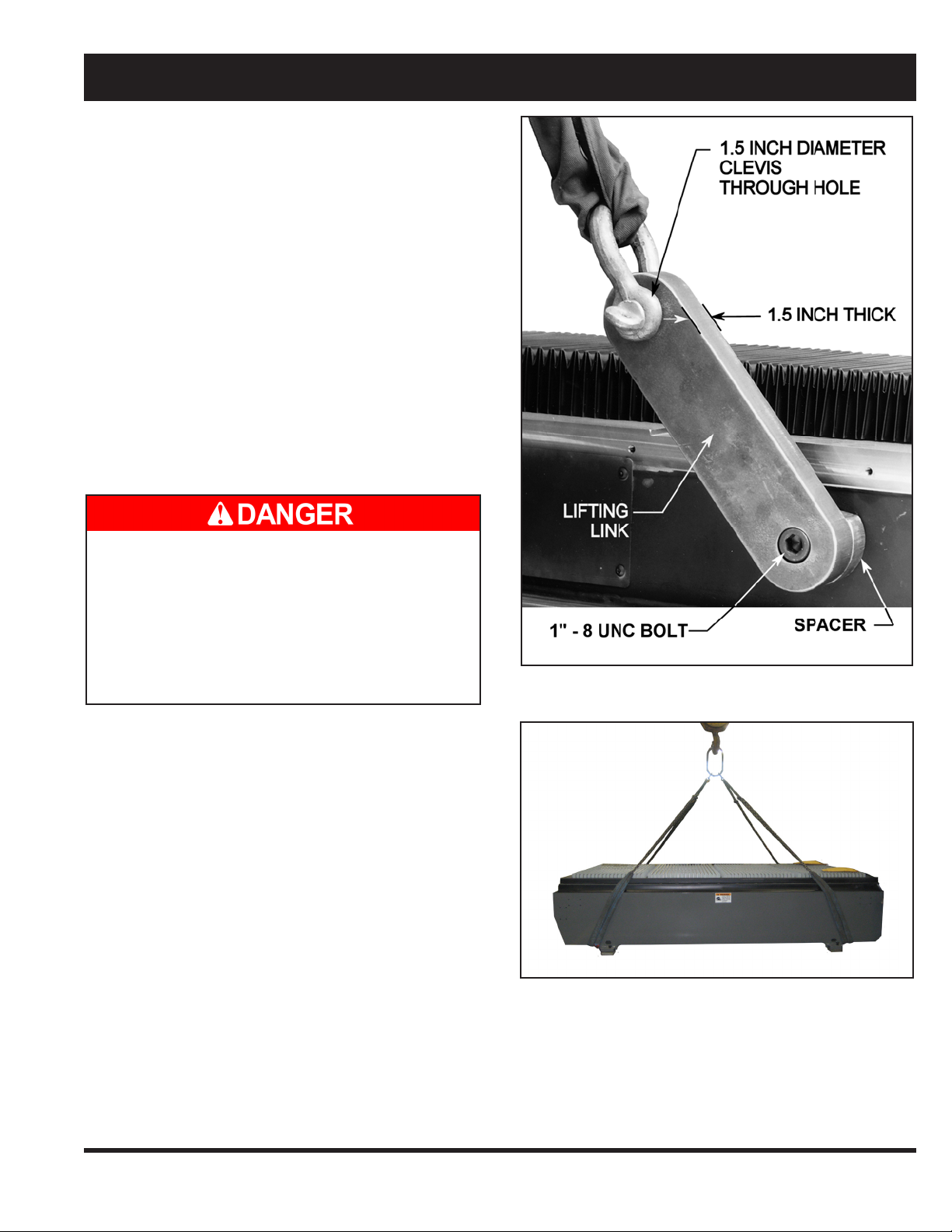
LIFTING AND MOVING
Machine weights are provided in Section 4 SPECIFICATIONS.
The main frame is lifted using four standard lifting clevises
attached to four lifting links (C.I. Part # 920584) with
spacers (C.I. Part # 920585). The four lifting links (supplied
by CINCINNATI) are attached to the inside of the main
frame with 1”-8 UNC SHCS bolts. See Figure 2-1.
When lifting with chains, cables, or straps, use the maximum
length possible to reduce the side loading generated at the
lift points. Use spreader bars or intermediate lifting beam
if ceiling height will not allow a high pick.
Before lifting the main frame, be sure that lifting
links (C.I. # 920584) and spacers (C.I. # 920585)
are installed. Do not use eyebolts or other devices
not designed for excessive side loads. Using
improper lifting devices could result in serious
injury or death to bystanders and/or cause
extensive damage to the main frame and ber
laser.
IMPORTANT: Extreme care must be taken not to subject
the machine to shock loads. The machine must be
lifted and set down gently.
The load frame can be lifted using straps with S-hooks at
each of the four outer corners. The S-hooks are hooked in
the access holes located at the bottom of the load frame.
Adequate padding must be used at all points to protect the
machine’s nish. The straps can be gathered and lifted with
a hook attachment. See Figure 2-2.
Figure 2-1 Lifting Main Frame
2-1
Figure 2-2 Lifting Load Frame
EM-550 (N-04/11)
FOUNDATION
A Certied Foundation Plan drawing is provided shortly
after the machine is ordered. This drawing provides
the user with detailed information required to locate the
equipment and the eight machine anchors. The customer
should prepare the eight anchor locations prior to arrival of
the equipment. The eight pads must be pre-leveled to lie in
the same plane within .50 inches (12.7 mm), and the anchor
holes should be drilled as specied on the Foundation
Plan drawing. CINCINNATI INCORPORATED provides
anchors, studs, nuts, and shims for nal leveling.
Connect the customer-furnished fume exhaust system 4.
to the fume duct exit port.
Complete preliminary leveling procedure described 5.
below.
CINCINNATI Service will install the operator control 6.
station and complete nal electrical connections to the
control.
Install gas lines, wiring, and hoses as described in the 7.
pre-installation manual.
If the machine is to be installed near shock inducing
equipment such as punch presses, turret punches, etc.,
contact CINCINNATI INCORPORATED.
INSTALLATION OF MACHINE
After setting the machine on the anchor studs, place
washers and nuts on studs, but do not tighten. Installation
consists of the following steps:
Remove lifting clevises and spacers. 1.
Remove all steel banding and protective wrappings.2.
Install fume fan (optional) and fume duct connecting 3.
to fume plenum with ange and fasteners provided.
Seal connection with a bead of RTV silicone. Make
the electrical connection to the fan drive motor with
wiring provided.
CHILLER
The water chiller is a free-standing unit requiring only
oor support. Cooling lines are connected to the main
frame at the gas and coolant location mounted to the rear
of the machine. Hoses are furnished to connect the chiller
when located as shown on the Foundation Plan. Consult
CINCINNATI INCORPORATED if an alternative chiller
location is required. See Section 4 - SPECIFICATIONS
for chiller uid specications.
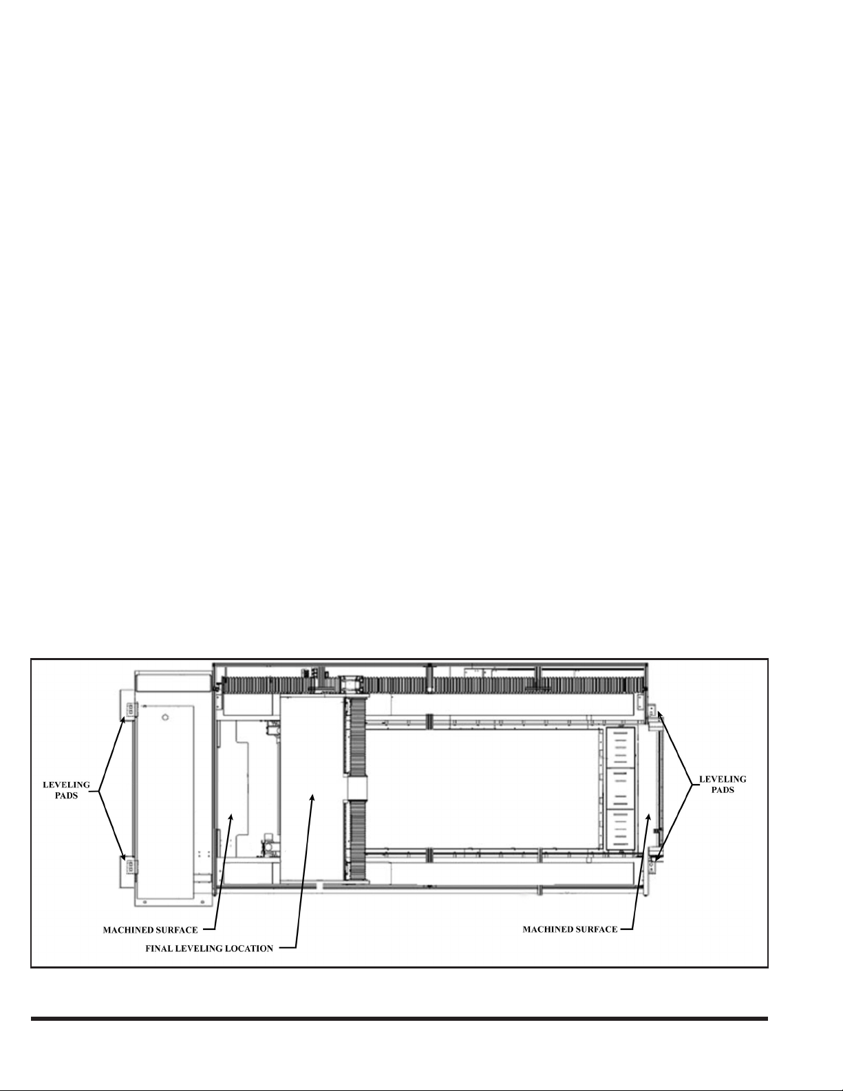
LEVELING
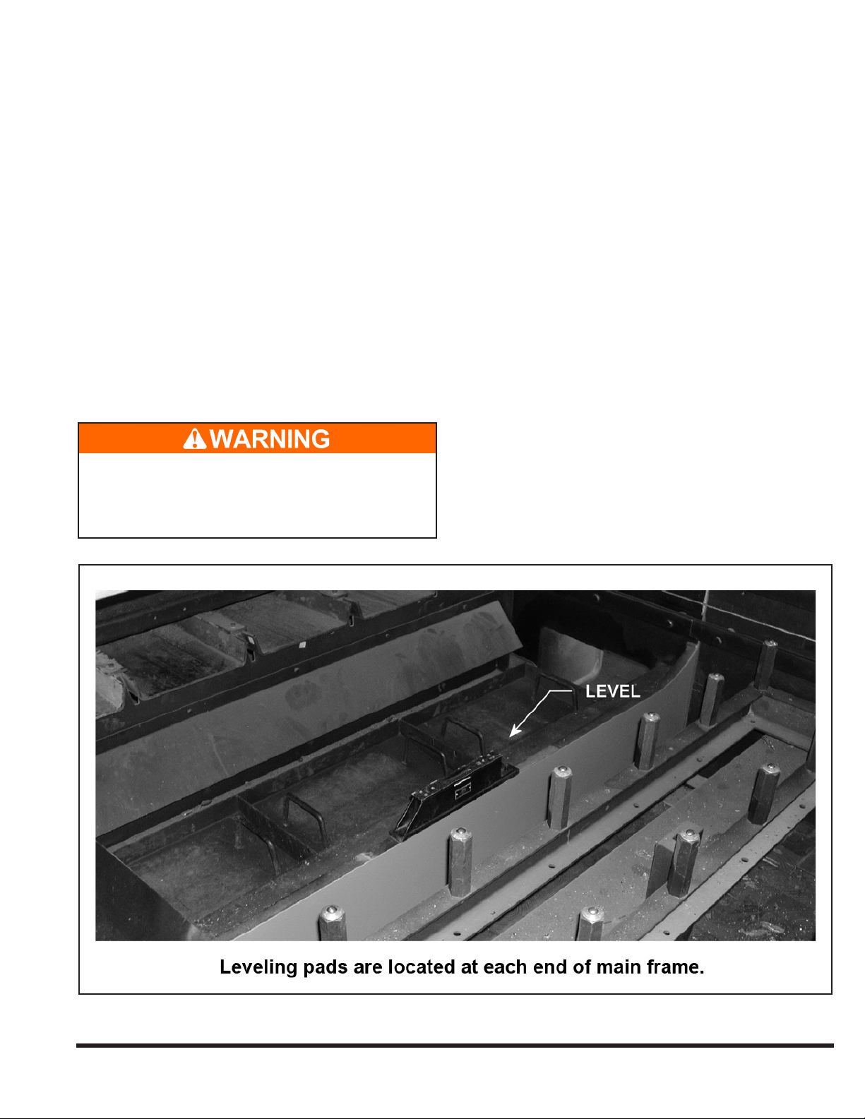
Main frame leveling adjustments are made using
jackscrews provided at the mounting pads. Figure 2-3
shows the mounting pads. The machine foot mounting
pads are located on the outside surface of the main frame
in the four corners.
EM-550 (N-04/11)
Figure 2-3 Main Frame Leveling Adjustments
2-2
Slotted shims are inserted between the machine foot and
steel spacer block as shown on the Foundation Plan drawing.
After shims are inserted, jackscrews are to be backed off
or removed. The procedure for leveling is described in the
next sections.
PRELIMINARY LEVELING
To check cross-leveling, place a precision level on 1.
machined pads on each end of the main frame. For
preliminary leveling, a level with .004 inch/ft. precision
is sufcient (0.33 mm per meter). See Figures 2-3 and
2-4. Lift machine with jackscrews and shim under
mounting feet (shims are provided).
Longitudinal level is checked on the top of the X-axis 2.
guide way. Adjust as described above. (See Figure
2-5.) Longitudinal leveling does not require a precision
level.
A very powerful magnetic eld surrounds the
magnet track. Keep all metal (steel) tools away
from this track. Place a piece of wood (2x4) over
the magnetic track to protect it and personnel.
FINAL LEVELING
Final leveling should be done with a CINCINNATI
INCORPORATED Service Representative present.
The purpose of nal leveling is to ensure that the gantry
does not rotate about the X-axis as the gantry moves from
end-to-end. Excessive rotation will cause laser beam
misalignment during operation.
Use a 15 inch (380 mm) precision spirit level with a 1.
sensitivity of .0005 inch/ft. (0.04 mm per meter).
Place the level on the top of the gantry and position 2.
the gantry at X = 0. See Figure 2-6. The gantry may be
moved by manually pushing it when drives are off, or
by using JOG mode when drives are on.
The top of the gantry is not machined. Therefore, it 3.
will be necessary to shim one or both ends of the level
to establish a reference reading and make the level
sit solidly in place. Paper shims can be used for this
purpose.
Figure 2-4 Cross Leveling (Preliminary)
2-3
EM-550 (N-04/11)
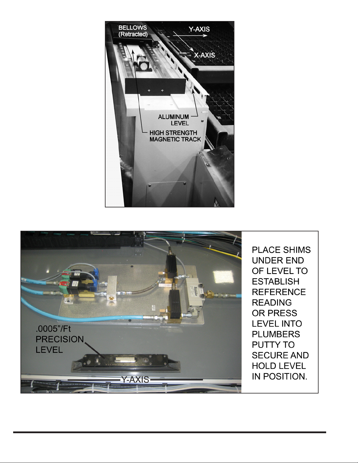
Figure 2-5 Longitudinal Leveling
EM-550 (N-04/11)
Figure 2-6 Final Leveling with Precision Level
2-4

Observe the position of the bubble while moving 4.
the gantry from X = 0 to X = Maximum travel. The
maximum acceptable deviation is one division of the
level (.0005 inch per ft. or 0.04 mm per meter) as the
gantry moves from end-to-end. This ensures that the
frame is not in a twist. Adjust as described above, using
jackscrews to add or remove shims under mounting
feet.
When Step 4 is complete, lightly tighten anchor nuts 5.
and recheck level as specied in Step 4. Verify that
jacking screws are backed off and not supporting the
machine.
Tighten the anchor nuts.6.
Repeat Step 4 as a nal level check.7.
The standard electrical input is 460 volt, 3 phase, and
50/60 hertz. The machine must be properly grounded in
accordance with the National Electric Code NFPA 70, 2002
edition, article 250, sections 50 through 70. CINCINNATI
INCORPORATED recommends using an individual
electrode per article 250.52 (5) to avoid interference from
other equipment. Place ground electrode as indicated
on Foundation Plan drawing. Do not start the machine
until Section 3 - SAFETY of this manual has been read
thoroughly and a CINCINNATI INCORPORATED
Service Representative is present.
The machine controls have been designed to operate
satisfactorily with good quality incoming electrical power.
It is important that the electrical power be free of excessive
noise and power uctuations. Refer to the pre-installation
instructions for details of input power requirements.
ELECTRICAL CONNECTION
Each Laser System customer is supplied a complete set
of Foundation Plan drawings prior to machine shipment.
The electrical load requirements and connection points
are called out on these drawings. Be certain that a suitably
sized wire is brought to the main disconnect and the proper
voltage is supplied.
SAFETY DEVICES
DO NOT START THE MACHINE UNTIL SECTION
3 - SAFETY OF THIS MANUAL HAS BEEN
THOROUGHLY READ AND A CINCINNATI
INCORPORATED SERVICE REPRESENTATIVE IS
PRESENT.
2-5
EM-550 (N-04/11)

EM-550 (N-04/11)
2-6

SEcTION 3 SAFETY
SAFETY IS EVERYONE’S JOB
The CINCINNATI Laser System - Fiber Laser manufactured
by CINCINNATI INCORPORATED has been designed to
meet the highest order of reliability and ease of operator use.
This system has been certied under Federal Regulations
21 CFR, subpart J, as a Class 4 Laser product as required
by the Federal Radiation Control for Health and Safety
Act of 1968. This certication is on le with the Food and
Drug Administration “Center for Devices and Radiological
Health” (CDRH) Division, Ofce of Compliance, 2098
Gaither Road, Rockville, Maryland 20850.
CINCINNATI INCORPORATED recommends the
customer read and understand the requirements of the
American National Standard ANSI B11.21 entitled “Safety
Requirements for Design, Construction, Care, and Use of
Machine Tools Using Lasers for Processing Materials” and
ANSI Z136.1 entitled “American National Standard for
Safe Use of Lasers”. They are available from the American
National Standards Institute, 25 West 43rd Street, New
York, New York 10036.
For additional safety information, CINCINNATI
recommends:
Obtaining applicable safety data from:1.
National Safety Council, 1121 Spring Lake Drive, a.
Itasca, Illinois 60143-3201.
The Laser Institute of America, Suite 128, 13501 b.
Ingenuity Drive, Orlando, Florida 32826.
Determining responsibilities under state and local 2.
safety codes.
Requesting assistance from the loss prevention 3.
department of the workmen’s compensation carrier.
Personnel responsible for the Laser System operator
training program, maintenance, and manufacturing
operations must read and understand this Operation, Safety,
and Maintenance manual. No one should set up, operate, or
maintain this Laser System until thoroughly understanding
it and knowing how to do the job safely. Read this manual
in its entirety.
INTRODUCTION TO LASER SAFETY
The laser beam is a strong, highly directional beam of
energy that, if directed, reected, or focused upon an
object, will be partially absorbed. This absorbed energy
can raise the temperature of the object enough to cause
material changes at the point where the laser beam hits the
object. This process can also produce adverse biological
effects in human tissue.
A BRIEF DISCUSSION ON RADIATION
Radiation is energy radiated or given off in the form of
waves or particles. It is a general term used to describe
energy emitted from a wide range of sources. Some
sources are man-made, such as radio waves, and some
occur naturally, such as the rays coming from the sun. To
keep track of all the various kinds of radiation, scientists
developed a system to separate radiation by the length of
the wave (or frequency) being sent out by the source. This
is called the “electromagnetic spectrum”. This spectrum
covers the entire range of energy wavelengths from the
very short gamma rays to the much longer wavelength of
commercial electricity sent out from the electric company
(for example, 60 cycle current).
All forms of electromagnetic radiation travel at the
speed of light, but at differing frequencies. The longer
the wavelength is, the lower the frequency. The energy
transmitted by radiation is also related to its frequency.
Higher frequency radiation can transmit greater energy.
Some radiation interferes with the internal energy that
holds atoms together as molecules. If the energy of a ray
of radiation is great enough, it will attract electrons away
from an atom or add additional electrons to it. This is called
“ionizing” radiation. X-rays are an example of this type of
radiation. CINCINNATI Laser System - Fiber Lasers do
not use ionizing radiation.
Radiation that lacks the energy to deform atoms is
called “non-ionizing” radiation. This is the type used in
CINCINNATI Laser System - Fiber Laser. The IPG product
is a diode-pumped ytterbium ber laser. The laser beam is
emitted in a continuous wave (CW) at a xed wavelength
of 1.07 micrometers. This wavelength is invisible to the
human eye. It is just outside the visible spectrum in the
near-infrared region and has high heat energy.
Non-ionizing radiation can cause harm. This is a result of
the energy being absorbed and raising the temperature of
the part of the body being hit. Over time, the heat energy
being absorbed will reach a harmful level. This injury is
similar to a burn received by standing too close to a bonre
for too long or the burn from being out too long in the
sun.
If the body part exposed to non-ionizing radiation is the
hardened, dead-cell tissue of the outer skin, minor harm
will be done. A reddening of the tissue and mild soreness
might be the only result. However, if that same radiation
energy gets inside the body to less well-protected tissue,
the tissue may not only be heated, but may become
permanently damaged as well.
3-1
EM-550 (N-04/11)
For example, the eyes are very susceptible to radiation. The
cells of the cornea and retina are not protected by a layer
of dead skin and thus can be damaged much easier than
the skin. The eye should always be protected from radiated
energy. Eye hazards and eye protection are covered in more
detail later in this section.
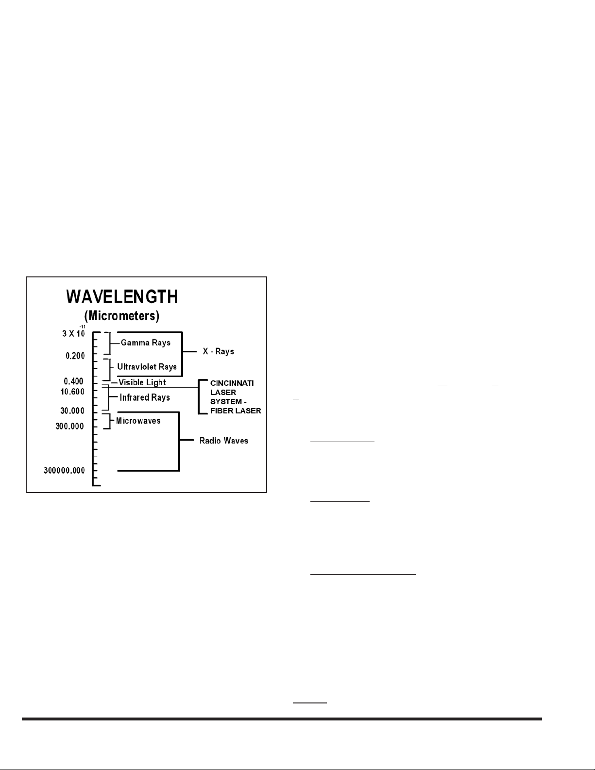
Figure 3-1 is a chart of the electromagnetic spectrum. The
CINCINNATI Laser System - Fiber Laser operates at a
wavelength of 1.07 micrometers. As shown in the chart,
this wavelength is just above the visible light spectrum in
the infrared zone.
In 1968, the U.S. Government passed a law regulating
products used in the United States that radiate energy.
The law is the “Radiation Control for Health and Safety
Act of 1968”. This law sets standards of performance for
electrical products that emit radiation. These are called
U. S. Federal Laser Product Performance Standards or
FLPPS. Manufacturers use FLPPS to ensure the design and
manufacture of their product properly controls radiation
hazards before the product is released to their customers.
Examples of some of the products covered under this law
are x-ray machines, microwave ovens, hair dryers, and all
types of lasers.
This brief introduction has been prepared to alleviate any
unwarranted concerns regarding laser radiation safety.
A more detailed discussion can be obtained in OSHA
Publication 8-1.7 entitled “Guidelines for Laser Safety and
Hazard Assessment”.
The Federal Standards covering Lasers and Laser Products
(for example, devices or machines containing a laser) are
covered in the Federal Register at 21 CFR Part 1040. In
these standards, the level of radiation accessible to persons
is used to group lasers into one of four classes. The classes
are Class 1, Class 2, Class 3, and Class 4. These classes or
risk categories establish the hazard controls required in the
product’s design before a manufacturer can turn a product
over to a user.
Research studies, along with an understanding of the
hazards of sunlight and conventional, man-made light
sources have permitted scientists to establish safe exposure
limits for nearly all types of laser radiation. Laser safety
specialists call these limits Maximum Permissible
Exposures (MPE’s).
Of the standards and publications that apply to users of
CINCINNATI Laser Systems, three will be most helpful:
ANSI B11.211. “American National Standard for
Machines Using Lasers”. The contents of this standard
came from the users and manufacturers of the machines
that use laser generated beams to process material.
Figure 3-1 Electromagnetic Spectrum
SAFETY STANDARDS AND PUBLICATIONS
There are a wide variety of laser safety standards and
publications. These include regulations of the federal
government and of several state and local governments.
Additionally there are non-regulatory standards, such
as the ones of the American National Standards Institute
(ANSI) and of the American Conference of Governmental
Industrial Hygienists (ACGIH). Internationally, the World
Health Organization (WHO) has laser safety guidelines,
and the International Electrotechnical Commission (IEC)
has been developing laser safety standards.
EM-550 (N-04/11)
ANSI Z136.12. “American National Standard for Safe
Use of Lasers”. This standard, which is technical in
content, was developed by the research and health
community to cover all types of lasers and laser
applications.
OSHA Publication 8-1.73. “Guidelines for Laser Safety
and Hazard Assessment”. This was developed for
OSHA eld personnel to help in their job of enforcing
workplace safety standards.
LASER HAZARD CLASSIFICATION
As previously indicated, laser products are placed into one
of four classes. These are:
Class 1 A Class 1 laser is considered safe based upon
3-2

current medical knowledge. This class includes all
lasers or laser systems which cannot emit levels of
optical radiation above the exposure limits for the eye
under any exposure conditions inherent in the design of
the laser product.
Class 2 A Class 2 laser or laser system must emit a visible
laser beam, whose natural brightness will limit exposure
by making the eye turn away. Momentary viewing is not
considered hazardous since the average radiant power
limit on this type of device must not exceed 1 milliwatt
(mW).
spelled out for all workers involved. The plan has four
worker categories. The Laser Safety Ofcer (LSO) is one
category and the other categories are for personnel working
in laser operations, plant maintenance, and laser service.
LASER SAFETY OFFICER
When an organization uses powerful laser products such
as those strong enough to cut metal, it is recommended
that someone in the organization be designated the Laser
Safety Ofcer (LSO). This is especially true when dealing
with Class 4 lasers whether they are embedded in a full
enclosure and called Class 1 systems or not.
Class 3 A Class 3 laser or laser system can emit any
wavelength, visible or non-visible. The Class 3 laser
is divided into two subclasses, Class 3a and Class 3b.
These lasers and laser systems are not considered a re
hazard or a serious skin hazard. Any CW (continuous
wave) laser that is not a Class 1 or Class 2 is a Class 3
device if its output power is 0.5 watts or less. Since the
output beam of such a laser is denitely hazardous when
the beam is allowed to directly enter the eye, control
measures for the Class 3 lasers and laser systems center
on eliminating this possibility.
Class 4 A Class 4 laser or laser system is any that exceeds
the output limits (Accessible Emission Limits, AEL’s)
of a Class 3 device. As would be expected, these lasers
may be a re and skin hazard, a diffuse reection hazard,
or both. Very stringent control measures are required
for a Class 4 laser or laser system.
Because of the power needed to cut metal, all lasers
used to cut metal are Class 4 lasers. Some Class 4 lasers
are embedded in enclosures or rooms and called Class
1 laser products or Class 1 laser systems. However,
control measures must still be established to insure that
the enclosure is maintained and that proper operating
procedures are followed.
CONTROL MEASURES
The CINCINNATI Laser System - Fiber Laser has been
designed and manufactured using the highest engineering
control measures practical. However, even these high
standards have limitations. Laser safety requirements
call for administrative and procedural controls to be
incorporated in the use of lasers in order to minimize or
eliminate the potential of personal injury during laser
operation.
Laser safety experts have determined that the best way to
control hazards presented by laser products is to establish
a clear plan of hazard control with specic responsibilities
The LSO should be an employee who is part of the
management organization. The LSO must be given the
responsibility and authority to monitor and enforce the
procedures established for controlling laser hazards. Unless
a great number of laser products are involved, this will not
be a full-time job but daily auditing of work procedures is
often a good idea. The LSO is responsible for seeing that
written standard operating procedures (SOP) for the laser
system are available. The information needed to establish
these SOP’s will come from the material provided by the
laser system manufacturer, auxiliary equipment providers,
and company safety rules. Each operator, maintenance
person, or laser service person should have access to these
SOP’s and fully understand their content.
OPERATING PERSONNEL
These people are responsible for the productive use of
the laser cutting system over the full range of its intended
function. These persons should be thoroughly familiar with
all operating controls, adjustments, and hazards associated
with their function.
MAINTENANCE PERSONNEL
Laser safety procedures classify Maintenance level tasks
as those done on machinery when the laser beam hazards
are not present. Therefore, maintenance personnel are
responsible for procedures that are completed in and
around a laser system with the laser power off. Maintenance
personnel should be thoroughly trained in the performance
of those procedures.
SERVICE PERSONNEL
Service personnel do the work required to maintain the
laser system. They must have the complete knowledge
of laser hazards and the controls provided by the system
manufacturer for their protection from those hazards. They
are responsible for doing the procedures and adjustments
described in the manufacturer’s service manual. The duty
of a service person requires a higher level of training and
education than that of the maintenance function.
3-3
EM-550 (N-04/11)
 Loading...