


 Loading...
Section 7 |
Operation |
|
|
|
|
|
|
A SUPPLEMENT to the OPERATION MANUAL FOR THE
CINCINNATI CL-900 Series
Laser System
For CINCINNATI Laser Control Software Version 8.3
CINCINNATIR
C I N C I N N AT I I N C O R P O R AT E D C I N C I N N A T I, OHIO 4 5 2 1 1
EM-551 (N-04/11) |
COPYRIGHT 2011 |
|
CINCINNATI INCORPORATED |

SSECTIONTI X7::operationtitle |
CONTENTS |
|
|
|
|
INTRODUCTION
HMI Overview
Laser System Display window............................................................ |
7-1 |
MENU BAR............................................................................................... |
7-2 |
TOOL BAR................................................................................................ |
7-2 |
STATUS INDICATORS CONTROL BAR................................................... |
7-3 |
PROCESS STATUS BAR......................................................................... |
7-3 |
APPLICATION WORKSPACE.................................................................. |
7-3 |
OPERATOR CONSOLE CONTROL BAR................................................. |
7-4 |
PROGRAM STATUS BAR........................................................................ |
7-4 |
MAIN STATUS BAR.................................................................................. |
7-4 |
File Types.................................................................................................... |
7-5 |
NC PROGRAM FILE................................................................................. |
7-5 |
PROCESS PARAMETER FILE................................................................. |
7-5 |
BATCH PROGRAM FILE.......................................................................... |
7-6 |
CNC Run Window....................................................................................... |
7-7 |
CONTROL bars
Operator Console.................................................................................. |
7-8 |
PROGRAM MODES................................................................................. |
7-8 |
LASER CONTROLS............................................................................... |
7-10 |
OVERRIDE SETTINGS.......................................................................... |
7-10 |
OPERATING MODES............................................................................. |
7-11 |
Override Adjust .................................................................................... |
7-12 |
Auxiliary Functions.............................................................................. |
7-13 |
Menu Commands
File Menu................................................................................................... |
7-14 |
NEW........................................................................................................ |
7-14 |
OPEN...................................................................................................... |
7-14 |
QUICK FILE OPEN................................................................................. |
7-16 |
OPEN LOADED PROGRAM................................................................... |
7-16 |
OPEN CURRENT PROCESS................................................................. |
7-16 |
CLOSE.................................................................................................... |
7-17 |
SAVE....................................................................................................... |
7-17 |
SAVE AS................................................................................................. |
7-17 |
LOAD NC PROGRAM............................................................................. |
7-18 |
LOAD CURRENT PROGRAM................................................................ |
7-18 |
LOAD CURRENT BATCH....................................................................... |
7-19 |
PLOT NC PROGRAMS........................................................................... |
7-19 |
RESTART LOADED PROGRAM............................................................ |
7-20 |
PRINT..................................................................................................... |
7-21 |
PRINT PREVIEW.................................................................................... |
7-22 |
PRINT SETUP........................................................................................ |
7-22 |
MRU FILE LIST....................................................................................... |
7-23 |
OPEN OPERATOR LOG........................................................................ |
7-23 |
EXIT........................................................................................................ |
7-23 |
Edit Menu.................................................................................................. |
7-23 |
UNDO…..................................................................................................7-24 |
|
CUT......................................................................................................... |
7-24 |
COPY...................................................................................................... |
7-24 |
PASTE..................................................................................................... |
7-24 |
FIND........................................................................................................ |
7-24 |
REPLACE............................................................................................... |
7-25 |
View Menu................................................................................................. |
7-25 |
CONTROL BAR...................................................................................... |
7-25 |
LANGUAGE............................................................................................ |
7-26 |
UNITS..................................................................................................... |
7-27 |
ALARMS AND MESSAGES WINDOW................................................... |
7-27 |
EM-551 (N-04/11)

AXES POSITIONS.................................................................................. |
7-28 |
MODAL G CODES.................................................................................. |
7-29 |
ALL POSITION INFORMATION.............................................................. |
7-29 |
RUN WINDOW GRAPHICS.................................................................... |
7-30 |
WINDOW ZOOMING.............................................................................. |
7-30 |
Maintenance Menu................................................................................ |
7-31 |
CONFIGURATION.................................................................................. |
7-31 |
DIAGNOSTICS....................................................................................... |
7-40 |
Pallet Gate Control...................................................................... |
7-43 |
STATISTICS............................................................................................ |
7-44 |
Laser Menu............................................................................................... |
7-45 |
LASER STATUS MONITOR.................................................................... |
7-45 |
AUTO SHUT-DOWN............................................................................... |
7-46 |
LASER DIAGNOSTICS........................................................................... |
7-47 |
Variables Menu....................................................................................... |
7-48 |
LOCAL/GLOBAL VARIABLES................................................................ |
7-48 |
USER I/O VARIABLES............................................................................ |
7-48 |
WORK OFFSETS................................................................................... |
7-49 |
MACHINE OFFSETS.............................................................................. |
7-49 |
Utilities Menu.......................................................................................... |
7-49 |
STANDOFF CALIBRATION.................................................................... |
7-50 |
OPERATOR SETUP............................................................................... |
7-50 |
LENS CENTERING................................................................................. |
7-53 |
SPEED GAS........................................................................................... |
7-55 |
Window Menu........................................................................................... |
7-55 |
CASCADE............................................................................................... |
7-55 |
TILE......................................................................................................... |
7-55 |
ARRANGE ICONS.................................................................................. |
7-55 |
WINDOW 1, 2 ........................................................................................ |
7-55 |
Help Menu................................................................................................. |
7-56 |
TOPICS................................................................................................... |
7-56 |
MANUALS............................................................................................... |
7-56 |
ABOUT CINCINNATI LASER SYSTEM.................................................. |
7-56 |
Cutting Process Parameters
Introduction........................................................................................... |
7-57 |
Process Parameter Window............................................................. |
7-58 |
PIERCE PARAMETERS......................................................................... |
7-58 |
RAMPED PIERCE PARAMETERS......................................................... |
7-59 |
RAPID PIERCE PARAMETERS............................................................. |
7-60 |
CUT PARAMETERS............................................................................... |
7-61 |
FOCUS PARAMETERS.......................................................................... |
7-64 |
PROCESS PARAMETER NOTES.......................................................... |
7-65 |
Start-up and Shut-down
Laser System Start-up........................................................................ |
7-65 |
Chiller Warm-up..................................................................................... |
7-67 |
Shutting Down the Laser System................................................... |
7-68 |
Calibration and Adjustment Procedures
Nozzle Standoff Calibration........................................................... |
7-69 |
NONCONTACT STANDOFF SENSING ................................................. |
7-69 |
Laser Shot............................................................................................... |
7-70 |
SETUP FOR A LASER SHOT................................................................. |
7-70 |
TAKING A LASER SHOT........................................................................ |
7-71 |
Centering the Focusing Lens.......................................................... |
7-71 |
LENS CENTERING PROCEDURE......................................................... |
7-72 |
Lens Focal Point Location................................................................. |
7-75 |
FOCUS CALIBRATION - AUTO FOCUS HEAD .................................... |
7-76 |
Assist Gas Pressure Adjustment................................................... |
7-77 |
Rapid Pierce Adjustments................................................................. |
7-77 |
Cutting Procedures
First Run of Parts................................................................................ |
7-78 |
Error Recovery.................................................................................... |
7-80 |
CUTTING HEAD BREAKAWAY.............................................................. |
7-80 |
EM-551 (N-04/11)

RESTARTING A PROGRAM................................................................... |
7-80 |
Batch mode Program Execution..................................................... |
7-81 |
Machine Setup Checking..................................................................... |
7-82 |
Auto Focus Cutting Head
Focus Control System Configuration........................................ |
7-84 |
Auto Focus Setup.................................................................................. |
7-85 |
FOCUS CONTROL SYSTEM HOME OFFSETS.................................... |
7-85 |
FOCUS SETUP FOR LENS CENTERING ............................................ |
7-86 |
Focus-Related Process Parameters............................................ |
7-87 |
Auto Focus Operation......................................................................... |
7-87 |
HOMING THE FOCUS CONTROL SYSTEM......................................... |
7-87 |
Windows Administration
Manager Account................................................................................. |
7-89 |
LASER UTILITIES FOLDER................................................................... |
7-89 |
SOFTWARE INSTALLATION AND UPGRADES.................................... |
7-90 |
Setup Account........................................................................................ |
7-90 |
SOFTWARE INSTALLATION AND UPGRADES.................................... |
7-91 |
EMERGENCY REPAIR DISK................................................................. |
7-91 |
NETWORK SETUP................................................................................. |
7-91 |
JOINING A DOMAIN............................................................................... |
7-91 |
Drive Designations............................................................................... |
7-92 |
MAPPING NETWORK DRIVES.............................................................. |
7-92 |
Backing up THE control..................................................................... |
7-92 |
Multiple Operator User Accounts................................................ |
7-92 |
Touchscreen Calibration.................................................................. |
7-92 |
Alarms and Messages
Operator FYI Messages....................................................................... |
7-93 |
System Alarms........................................................................................ |
7-95 |
Program Errors................................................................................. |
7-101 |
Laser Alarms......................................................................................... |
7-104 |
Troubleshooting................................................................................ |
7-104 |
Laser NC Programming
Standard G Codes............................................................................... |
7-105 |
G00 RAPID TRAVERSE MOVE............................................................ |
7-105 |
G01 LINEAR MOVE.............................................................................. |
7-106 |
G02 AND G03 ARC MOVE................................................................... |
7-106 |
G04 DWELL.......................................................................................... |
7-108 |
G09 EXACT STOP (ONE BLOCK)....................................................... |
7-109 |
G20 INCH MODE, G21 METRIC MODE.............................................. |
7-109 |
G31 POSITION CAPTURE MOVE....................................................... |
7-109 |
G40, G41, AND G42 KERF COMPENSATION..................................... |
7-109 |
G50 AND G51 COORDINATE SYSTEM SCALING.............................. |
7-111 |
G52 LOCAL WORK COORDINATE SYSTEM...................................... |
7-112 |
G53 RAPID MOVE TO MACHINE COORDINATES............................. |
7-112 |
G54…G59 WORK COORDINATE SYSTEM SELECTION .................. |
7-113 |
G61 AND G64 EXACT STOP MODE.................................................... |
7-113 |
G65 SUB-PROGRAM CALL ................................................................ |
7-113 |
G68 WORK COORDINATE ROTATION............................................... |
7-113 |
G90 AND G91 ABSOLUTE AND INCREMENTAL MODE..................... |
7-114 |
G92 WORK COORDINATE SYSTEM SETTING.................................. |
7-114 |
Custom G Codes................................................................................... |
7-115 |
G84 AND G85 START CUTTING SEQUENCE..................................... |
7-115 |
G89 SET PROCESS PARAMETERS................................................... |
7-117 |
G102 SET ADDITIONAL PROCESS PARAMETERS........................... |
7-119 |
G103 SET RAMPED PIERCE PARAMETERS..................................... |
7-119 |
G120 AND G121 NON-STOP CUTTING.............................................. |
7-120 |
G123, G124, AND G125 VELOCITY BLENDING................................. |
7-122 |
M Codes................................................................................................... |
7-123 |
M00 PROGRAM STOP......................................................................... |
7-123 |
M01 OPTIONAL STOP......................................................................... |
7-123 |
M02 END OF PROGRAM..................................................................... |
7-124 |
M30 END OF PROGRAM / REWIND................................................... |
7-124 |
EM-551 (N-04/11)

M35 BEAM OFF.................................................................................... |
7-124 |
M36 Z HOLD MODE............................................................................. |
7-124 |
M37 BEAM AND GAS OFF .................................................................. |
7-124 |
M38 Z HOLD MODE (TIMED)............................................................... |
7-124 |
M41 Z DOWN........................................................................................ |
7-125 |
M42 Z UP.............................................................................................. |
7-125 |
M43 LOWER PALLET SPECIAL FUNCTION ...................................... |
7-125 |
M44 DISABLE LOWER PALLET SPECIAL FUNCTION ...................... |
7-126 |
M45 OPTIONAL STANDOFF MODE.................................................... |
7-126 |
M47 PARTIAL Z UP ............................................................................. |
7-127 |
M48 FEEDRATE OVERRIDE DISABLE .............................................. |
7-127 |
M49 FEEDRATE OVERRIDE ENABLE................................................ |
7-127 |
M50 SWITCH PALLETS....................................................................... |
7-127 |
M51 AUXILIARY OUTPUT (TIMED)..................................................... |
7-127 |
M67 OPTIONAL ASSIST GAS PRESSURE......................................... |
7-128 |
M90 BALL TRANSFER UP................................................................... |
7-128 |
M91 BALL TRANSFER DOWN............................................................. |
7-128 |
M98 SUBPROGRAM CALL.................................................................. |
7-128 |
M99 END SUBPROGRAM.................................................................... |
7-129 |
M130 AND M131 Z-AXIS ANTIDIVE..................................................... |
7-129 |
M135 SPEED GAS BEAM OFF............................................................ |
7-130 |
M151 AUXILIARY OUTPUT WITH CONFIRMATION........................... |
7-130 |
CINCINNATI Macros............................................................................... |
7-130 |
GRID MACROS.................................................................................... |
7-130 |
Cutting Macros................................................................................... |
7-134 |
G73 HOLE MACRO.............................................................................. |
7-134 |
G76 SLOT MACRO............................................................................... |
7-134 |
G79 LINE MACRO................................................................................ |
7-135 |
G83 OUTSIDE CIRCLE MACRO.......................................................... |
7-136 |
G86 OUTSIDE RECTANGLE MACRO................................................. |
7-136 |
G88 BOLT CIRCLE MACRO................................................................. |
7-137 |
G104 SHAPE MACRO.......................................................................... |
7-137 |
M2 LEAD-IN DESCRIPTION................................................................ |
7-139 |
G105 LEAD-IN MACRO........................................................................ |
7-140 |
Program Structure.......................................................................... |
7-141 |
PROGRAM NAME................................................................................ |
7-141 |
PROGRAM BODY................................................................................ |
7-141 |
BEAM ON AND OFF COMMANDS....................................................... |
7-142 |
PROGRAM COMMENTS...................................................................... |
7-142 |
PROGRAM LINE NUMBERS................................................................ |
7-142 |
BLOCK DELETE................................................................................... |
7-142 |
END OF PROGRAM............................................................................. |
7-143 |
SUBPROGRAMS AND MACROS......................................................... |
7-143 |
LOCAL VARIABLES.............................................................................. |
7-143 |
NESTED SUB-PROGRAM CALLS....................................................... |
7-145 |
Program Variables............................................................................. |
7-145 |
LOCAL AND COMMON VARIABLES.................................................... |
7-145 |
SYSTEM VARIABLES........................................................................... |
7-146 |
Auxiliary Functions............................................................................ |
7-149 |
MATH FUNCTIONS.............................................................................. |
7-149 |
LOGIC FUNCTIONS............................................................................. |
7-150 |
AUXILIARY COMMANDS..................................................................... |
7-152 |
WORKPIECE EDGE DETECTION....................................................... |
7-154 |
NC Code List........................................................................................... |
7-162 |
M CODE LIST....................................................................................... |
7-162 |
G CODE LIST....................................................................................... |
7-163 |
EM-551 (N-04/11)

EM-551 (N-04/11)

EM-551 (N-04/11)

CINCINNATI LASER SYSTEM SECTION 7
CINCINNATI CL-900 SERIES LASER SYSTEM - FIBER LASER
Supplement Manual, Section 7 - OPERATION, for CL-900 Models
This manual applies to all CL-900 Series Laser System - Fiber Lasers, including all frame sizes.
Control Software Versions
This document was last updated for compatibility with the following control software:
CNC/HMI software |
- 846540 |
Version 8.3 |
PLC software |
- 846539 |
Version 2 |
EM-551 (N-04/11)

EM-551 (N-04/11)

HMI Overview
The Human Machine Interface (HMI) is the means provided for interacting with the laser system control. The HMI tools consist of the Operator Control Station front panel and side panel pushbutton controls, the LCD monitor/touchscreen, the trackball pointing device, the keyboard, the remote station, and the Laser System CNC/HMI software. The pushbutton controls and remote station functions are described in SECTION 6 - MACHINE CONTROLS of EM-550, CL-900
Fiber Laser Operation, Safety, and Maintenance manual.
This chapter presents an overview of the software user interface. The touchscreen, trackball, and keyboard can be used to navigate around the user interface. The foundation of the software user interface is the Laser System Display window.
Laser System Display window
The Laser System Display window occupies the entire display screen on the operator control station. The main components of the Laser System Display window are the Title Bar, Menu Bar, Tool Bar, Status Indicators Control Bar, Application Workspace, Operator Console Control Bar, and Main Status Bar. A Process Status Bar, Program Modes Control Bar, and Program Status Bar may also be visible, depending on the current operating mode of the Laser System.
7-1 |
EM-551 (N-04/11) |
MENU BAR
The Menu Bar is the row of main menu titles across the top of the Laser System Display window. Selecting a menu title opens a pop-up menu displaying a list of menu commands. See the MENU COMMANDS section for a description of each command.
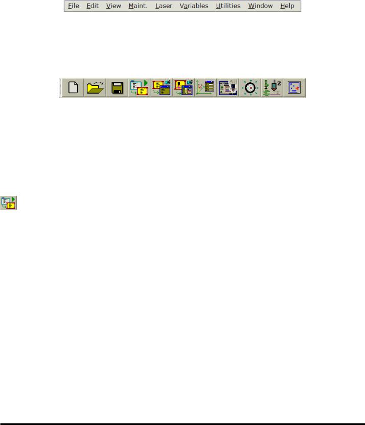
TOOL BAR
The Tool Bar, located below the Menu Bar, contains a row of buttons where each button corresponds to a menu command. The Tool Bar provides convenient, single-touch access to some of the more commonly used menu commands. The Tool Bar can be hidden or displayed by going to: View | Control Bars.
This list identifies which menu command is associated with each Tool Bar button:
 File | New
 File | Open
 File | Save
File | Load Current Program
 File | Open Loaded Program
 File | View Current Process
 View | View Axes Positions
 Utilities | Operator Setup
 Utilities | Lens Centering Mode
 Utilities | Standoff Calibration
 Open the CINCINNATI Laser Programming and Nesting application, if installed.
EM-551 (N-04/11) |
7-2 |
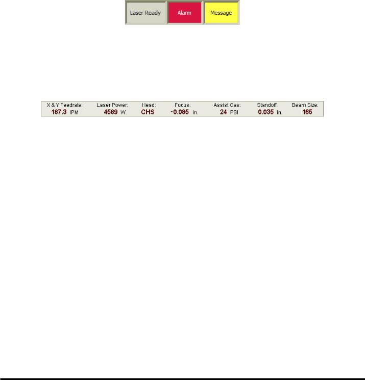
STATUS INDICATORS CONTROL BAR
The Status Indicators Control Bar, which is normally positioned to the right of the Tool Bar, consists of separate indicators for laser state: “alarm condition present” and “operator message ready”. The left-most indicator shows the current laser operating state. Click or touch this indicator for a shortcut to open the Laser Status window.The“Alarm”indicatorsignifies the presence of system alarms or laser alarms when its color is red.Aflashing red indicator means that one or more system alarms are active. A solid red indicator means that only laser alarms are active. A yellow “Message” indicator signifies that one or more operator FYI messages are pending. Both the “Alarm” and “Message” indicators can be used as shortcut buttons to open or close the Alarms and Messages window. The status indicators can be used as a shortcut to open or close the Laser Status window.
PROCESS STATUS BAR
The Process Status Bar, which is located below the Tool Bar, displays critical process information such as feedrate, laser power, beam focus position, assist gas pressure, and nozzle standoff. The Process Status Bar is only displayed when the Laser System is in Auto mode. All displayed values are updated in real time. While the control is in Auto mode, the Process Status Bar can be hidden or displayed by going to View | Control Bars | Process Status Bar.
APPLICATION WORKSPACE
The Application Workspace is the area (initially blank) which is below the Process Status Bar or Tool Bar and above the Program Status Bar. NC program windows, Process Parameter windows, and all other user-activated windows and dialogs will open in this area.
7-3 |
EM-551 (N-04/11) |

OPERATOR CONSOLE CONTROL BAR
The Operator Console Control Bar contains the user interface controls used by the machine operator to control and monitor the basic operating mode of the Laser System. See OPERATOR CONSOLE in the CONTROL BARS section, for information on this control bar.
PROGRAM STATUS BAR
The Program Status Bar, located just below the Application Workspace, displays the cutting program execution status. Like the Program Modes Control Bar and the Process Status Bar, this status bar is visible only when the control is in Auto mode.
The Program Status Bar is divided into two fields, the left field contains the file name of the currently loaded NC program. This field is empty when there is no NC program loaded into the control. The right field indicates the current state of the program execution subsystem. For example: “Program not loaded”, “Executing”, or “Program Stopped” may be displayed here.
MAIN STATUS BAR
The Main Status Bar is displayed at the bottom of the Laser Status Monitor window, and is used to display operator help messages and other general information. The Main Status Bar is divided into several sections. The section to the right of the CINCINNATI logo displays a brief description of Menu Bar and Tool Bar button commands as these items are selected with the trackball or keyboard.
To the right of the command description is the laser control system “heartbeat” indicator. A properly functioning control system is indicated by two alternately flashing green indicators. If either indicator stops flashing or turns red, power down the system and restart it. If this does not return the indicators to their proper state, contact CINCINNATI INCORPORATED Laser Service Department.
The next field to the right is the NC Program file line number of the line where the cursor is currently located. This field is blank if an NC Program Edit window is not the currently active window.
EM-551 (N-04/11) |
7-4 |
In the far right section of the Main Status Bar, the current time is displayed.
File Types
TheLaserSystemcontrolsoftwaregetstheinformationitneedstoexecutecuttingapplicationsfromtwotypesofdatafiles: NC Program files and Process Parameter files.Athird type of file, the Batch Program file, may be used if desired, to create a list of NC Program files to be executed in the specified order.
The File menu commands and Tool Bar buttons, described later, can be used to open these files for viewing/editing, and to create new files. When opening an existing file or creating a new file, a window will appear in theApplication Workspace, displaying the file’s contents. The Title Bar of each file view window contains the name of its file.
When a file is modified, it must be saved using File | Save or Tool Bar Save command before any changes will take effect. An asterisk “*” will appear next to the file name of any file that has been modified but not saved.
The following topics describe each of the three types of file and their view windows.
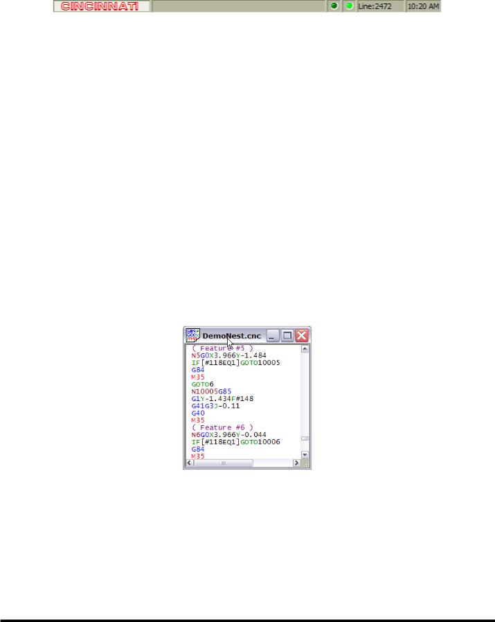
NC PROGRAM FILE
The NC Program file contains the NC codes that determine the part feature geometry and control the various machine cutting functions. NC programs, which may be as simple as a single part or as complex as multiple sheets of nested parts, are typically generated by nesting/post-processing software packages such as the CINCINNATI Laser Programming and Nesting Software application. NC Program file names should end with “.cnc” (ex: “Filename.cnc”).
When an NC Program file is opened, its contents are displayed in a Program Edit window. Program Edit windows use context coloring; distinct program components are displayed with different colors (G codes are blue, M codes are red, etc).
PROCESS PARAMETER FILE
The Process Parameter file contains settings used to control the power and focusing attributes of the laser beam and the cutting assist gas. Process Parameters are stored in multiple files, with a separate file for each distinct cutting process. All CINCINNATILaserSystems areshippedwithalibraryof Process Parameterfilescontainingthecuttingparametersettings recommended by CINCINNATI INCORPORATED. These files are stored in the “Cnclsr32/Material” folder on the laser control’s computer hard disk drive. These files can be modified to specify other cutting processes by creating new Process Parameter files with the preferred settings. Process Parameter file names should end with “.lib” (ex: “Filename.lib”).
G89 blocks in the NC Program file specify which Process Parameter file(s) will be used in each cutting application. See
CUSTOM G CODES in the LASER NC PROGRAMMING topic for more information on G89.
7-5 |
EM-551 (N-04/11) |
When a Process Parameter file is opened, the parameter settings are displayed in a Process Parameter window. See the
CUTTING PROCESS PARAMETERS topic for more information on process parameters.
Note: An “Active” or “Loaded” indicator: 
 may be displayed in the upper right corner of the Process
Parameter window. If a Process Parameter file that is loaded via a G89 block anywhere in the active NC program is open in a window, a yellow “Loaded” indicator will be displayed. If this file represents the currently active cutting process, then an orange “Active” indicator will be displayed.
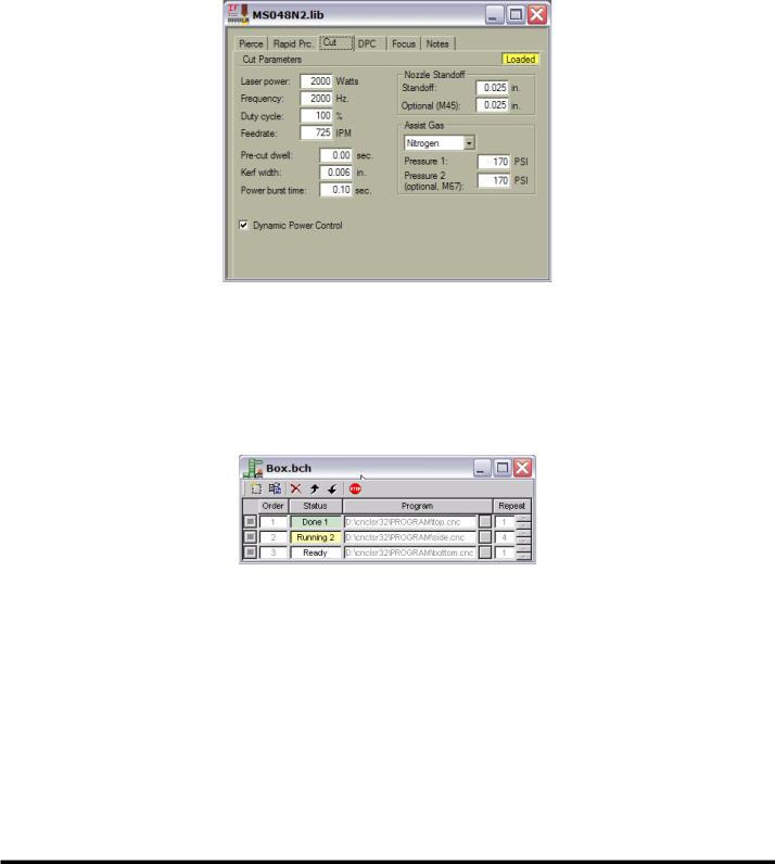
BATCH PROGRAM FILE
A Batch Program file is a list of NC Program files that will be loaded and executed in the order listed. It allows programs to be grouped together in a logical manner and allows the control to keep track of which programs have been completed and which program to load next. A Batch Program can contain up to one hundred program entries and each entry can be repeated up to one hundred times. Batch Program file names should end with “.bch” (ex: “Filename.bch”).
When a Batch Program file is opened, the parameter settings are displayed in a Batch Program window:
Creating a Batch Program
To create a new Batch Program:
1.Select File | New and then select “Batch”filetypeintheNew Selection window. Click “OK” to close the New Selection window.
2.In the new Batch Program window, select the “New Entry”  button until the window has enough rows for all NC programs that will be added to the batch.
3.In each row, enter the NC Program file name in the Program column by typing it directly or using the “Browse”  button to select it with the trackball.
4.Enter the number of times that each program will run in the Repeat column by typing it directly or by using the arrow buttons  .
.
EM-551 (N-04/11) |
7-6 |
5.If it becomes necessary to move or delete an entire row, select the row using the “Row Select”  button and then press the “Move Up”
  , “Move Down”
  , or “Delete Entry”
  button.
Editing a Batch Program
Batch Program editing functions are provided in the Batch Program window. The editing functions are:
Insert new row |
Inserts a new NC Program file entry after the selected entry or at the end of the list. |
Copy a row |
Copies the selected row and inserts the copy into the list after the selected row. |
Delete Entry |
Deletes the selected entry. |
Move Up |
Moves the selected entry up one row in the list. |
Move Down |
Moves the selected entry down one row in the list. |
Stop the Batch |
Stops a running Batch Program. |
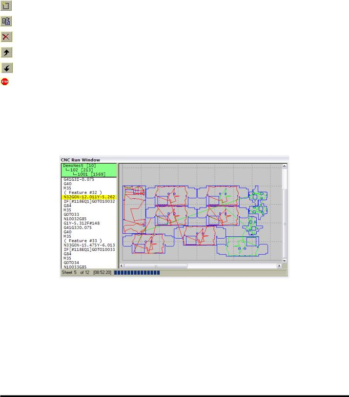
CNC Run Window
The CNC Run Window displays the execution status of the active cutting program, if a program is currently loaded. This window cannot be manually opened or closed. The control software will automatically display the CNC Run Window each time a part program is successfully loaded, and whenever the control enters Auto mode while a program is loaded. Likewise, the CNC Run Window will automatically close whenever the control enters Jog mode or Axes Home mode.
The CNC Run Window has two sections and a status bar. The left section displays the NC program code with the active block highlighted. To help locate the current position in an interrupted cutting program, the active subroutine name and line number are displayed in a green box at the top of the NC code section. All currently active subroutines are displayed, indented to the right to indicate the nesting depth for nested subroutines.
The right section is a graphical plot of the current sheet program. For each sheet, the status bar at the bottom of the window displays the sheet number, the remaining runtime, and a bar graph showing the percentage of completed program blocks. The plotting software interprets M50 as the start of another sheet.
Before the program starts each sheet, the plot shows all X-axis and Y-axis rapid moves in green. Contouring moves with the laser beam on are shown in blue. Contouring moves with the laser beam off are shown in yellow. As the program runs, the plot changes the color of all completed moves to red. To change the width of the plot section, select the divider between the left and right sections and drag it to another location. To change the viewing area of the plot, use any of the various Zoom
7-7 |
EM-551 (N-04/11) |
features. See WINDOW ZOOMING in the VIEW MENU section.
If desired, the plot section and status bar can be hidden, resulting in a much smaller CNC Run Window. See RUN WINDOW GRAPHICS in the VIEW MENU section.
CONTROL bars
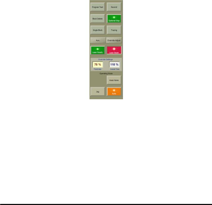
Operator Console
The Operator Console Control Bar contains four different groups of user controls: Program Modes, Laser Resonator, Override Settings, and Operating Mode. There are also two buttons that can be used to quickly open or close other control bars.
Selecting the “Aux.” button will open the Auxiliary Functions Control Bar if it is not currently open, or close it if it is currently open. Selecting the “Override Adjust” button will open the Override Adjust Control Bar if it is not currently open, or close it if it is currently open.
PROGRAM MODES
The top section of the Operator Console Control Bar contains controls that turn on or off the various program execution modes that affect how the control software executes NC programs. Each control is both a button and indicator for the corresponding mode. Like the button/indicators in the other control bars, these controls appear bright green (ON) when the corresponding mode is active, and dull green or gray (OFF) when the mode is not active.
The Laser Control Software automatically displays the Program Modes Control Bar each time the CNC control enters Auto mode. When the control enters Jog or Axes Home mode from Auto mode, this control bar will automatically close.
EM-551 (N-04/11) |
7-8 |
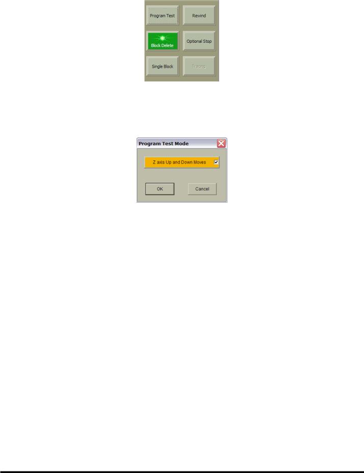
PROGRAM TEST MODE
Program Test Mode will run a part program without actually cutting material. Use the “Program Test” button to activate Program Test Mode. In this mode, the laser beam and assist gas will not turn on during program execution. Selecting the
“Program Test” button when Program Test Mode is off will cause the ‘Program Test Mode’dialog box to open.
The “Z-axis Up and Down Moves” button enables or disables Z-axis motion while Program Test Mode is active. If the box is not checked, the cutting head will not move up or down, and the program will ignore the Pierce dwell. Select “OK” to close the dialog and activate Program Test Mode; select “Cancel” to close the dialog without activating Program Test Mode.
Keyboard Shortcut: |
F2 |
REWIND
The “Rewind” button sets the first block of the active NC program as the next block to be executed when “CYCLE
START” is pressed. Use this function to restart the program from the beginning when program execution is interrupted. The “Rewind” button is disabled while program execution is in progress. Note that this button does not stay in the green (ON) state when selected, since it does not make a new mode active.
Keyboard Shortcut: |
F3 |
BLOCK DELETE MODE
While Block Delete mode is active, any block in the NC program that begins with the “ / ” (forward slash) character will not be executed. The “Block Delete” button activates Block Delete mode. Block Delete mode can be enabled/disabled at any time during program execution.
Keyboard Shortcut: |
F4 |
OPTIONAL STOP MODE
Optional Stop mode enables the use of M01 (or M1) in a program. Use the “Optional Stop” button to activate Optional Stop program execution mode. When Optional Stop mode is active, the control changes to the Cycle Stop condition when a program commands M01. Program execution resumes when “CYCLE START” is pressed. Optional Stop mode can be enabled/disabled at any time during program execution.
Keyboard Shortcut: |
F5 |
7-9 |
EM-551 (N-04/11) |
SINGLE BLOCK MODE
In Single Block mode, only one NC Program block will be executed each time “CYCLE START” is pressed. The “Single Block” button activates Single Block program execution mode.
Keyboard Shortcut: |
F6 |
TRACE MODE
The “Tracing” button activates program execution Trace mode. When Trace mode is active, the “TRACE FORWARD” and “TRACE REVERSE” buttons on the machine operator front panel are enabled. Tracing is used to recover from program interruptions; it allows the operator to step through the program in either the forward or reverse direction with the laser beam off, as long as the “TRACE FORWARD” or “TRACE REVERSE” button is pressed. See ERROR RECOVERY in the CUTTING PROCEDURES section.
Keyboard Shortcut: |
F7 |
Note: There is a limit to how far in reverse a program can be traced. As a program is running, a fixed number of executed program blocks are held in memory. This memory area, known as the “history buffer”, limits how far a program can be traced in reverse. Large programs may contain more blocks than the history buffer can hold. Attempts to trace backwards beyond the last block in the history buffer will cause the alarm “End of history buffer or beginning of program reached. Reverse tracing is disabled.”
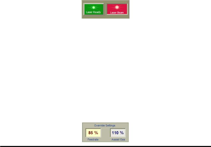
LASER CONTROLS
This part of the Operator Console Control Bar contains controls related to the laser.
Laser Ready: The “Laser Ready” button/indicator will appear bright green (ON) when the laser has finished its start up sequence and is ready to turn the beam on, and dull green or gray (OFF) when the laser is not ready to turn the beam on. If the “HIGH VOLTAGE” keyswitch on the Machine Operator Side Panel is in the LOCKED position, the indicator will be appear off, displaying an image of a padlock.
Selecting this button when Laser Ready is off commands the control to connect power to the laser main power supply, initiating the power-up sequence. During the power-up sequence, the indicator blinks on and off; when the power-up sequence is complete, the indicator will remain on. Selecting this button when Laser Ready is on commands the control to remove electrical power from the laser main power supply.
Laser Beam: This indicator displays the On/Off status of the laser beam. The “Laser Beam” indicator is red (ON) when the laser is producing a beam. The laser produces a beam in response to requests for laser power. Laser power can be requested by the cutting program or by the Lens Centering function. When the laser is not producing a beam, the indicator color is dull red or gray (OFF).
OVERRIDE SETTINGS
In the center section of the Operator Console Control Bar, the current values of the Jog/Feedrate and Assist Gas Override settings are displayed.
EM-551 (N-04/11) |
7-10 |
It is easy to change either override setting by selecting one of the override display boxes. This will cause the Override Adjust Control Bar to open. Once selected, that display box will change to a red text/yellow background color to indicate that the corresponding override is activated for adjustment in the Override Adjust Control Bar.
OPERATING MODES
The bottom section of the Operator Console Control Bar contains three button/indicator controls for the primary operating mode, and an “Alternate Mode” indicator.
Jog: This button/indicator activates Jog mode. While the control is in Jog mode, the “Jog” indicator color is amber. In Jog mode, the axis motion controls on the Operator Control Station front panel or the Remote Station can be used to manually move (“jog”) each machine axis individually. Cutting program execution is disabled while Jog mode is active. Most Maint. | Utilities functions, such as Lens Centering, are only enabled when the Laser System is in Jog mode. The control will remain in Jog mode until another mode is selected.
Auto: This button/indicator activates Auto mode. The Laser System must be in Auto mode in order to run cutting programs. While the control is in Auto mode, the “Auto” indicator color is amber, and most Maint. | Utilities functions, are disabled.The NCProgram files andProcess Parameter Files whilethecontrolis executing a programinAuto mode.The control will remain in Auto mode until another mode is selected.
Axes Home: This button/indicator activates Axes Home mode. When selected, the “Axes Home” button text changes to “Homing” and the color changes to amber. To home the axes, the main drives must be on with no system alarms present. The Axes Homing function begins when the operator presses the “CYCLE START” pushbutton. When all axes have moved to their reference positions, all axis motion stops, the Axes Home function ends and the control automatically changes to Jog mode.
Special Operating Mode
Special Operating Modes are alternate modes the Laser System is in while certain functions are active:
•Lens Centering
•Standoff Calibration
Note: The Laser System must be in Jog mode before a “Special Operating Mode” can be activated.
Special operating modes are typically modes in which the “CYCLE START” / “CYCLE STOP” buttons perform some unique function other than starting the execution of a cutting program. For example, Standoff Calibration is a “Special Operating Mode” since “CYCLE START” initiates the Noncontact Head standoff calibration sequence. When any of these special operating modes are active, the amber-colored “Alternate Modes” indicator will be visible, and the three primary operating mode buttons will be disabled.
7-11 |
EM-551 (N-04/11) |
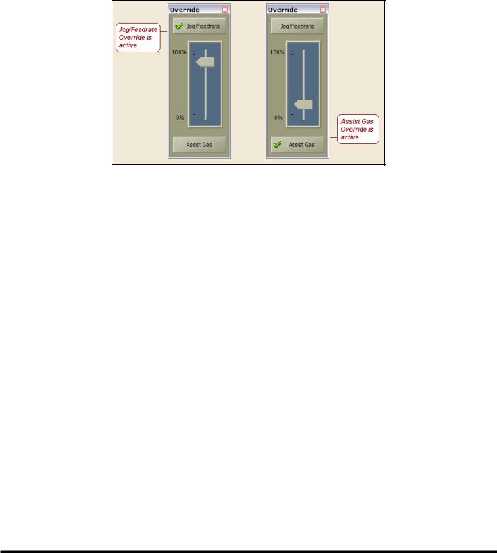
Override Adjust
The Override Adjust Control Bar contains a slider control that can be used to adjust the setting of either the Jog/Feedrate Override or the Assist Gas Override function. Only one override setting, the active override, is adjusted at a time. The active override is selected by selecting either the “Jog/Feedrate” or the “Assist Gas” button. The currently active override is indicated by a green check mark on the corresponding button and a yellow background color for the “Override Settings” indicator in the Operator Console Control Bar.
The Override Adjust Control Bar can be opened/closed in any of the following ways:
• Select the “Override Adjust” button in the Operator Console Control Bar.
▪ Selecteither“OverrideSettings”indicatorintheOperatorConsoleControlBar;thiswillalsomakethecorresponding override active.
• Go to: View | Control Bars | Overrides
There are several ways to change the slider control setting in the Override Adjust Control Bar:
•After selecting the slider control, the “Page Up” and “Page Down” keyboard keys will change the setting in 5% increments.
•The “Up Arrow” and “Down Arrow” keyboard keys change the setting in 1% increments.
•Select the “Slider Control” indicator with the trackball pointing device and then drag it to any setting.
•Rotate the wheel on the trackball pointing device after selecting the slider control.
Assist Gas Override: Thissettingmodifiestheprogrammedassistgaspressureusedforcutting.Forexample,iftheprogram specifies 200 PSI and the assist gas override is set to 75%, the actual cutting pressure will be: 75% of 200 PSI = 150 PSI.
This setting also affects the pressure achieved when assist gas is manually activated using one of the assist gas buttons on the Auxiliary Functions Control Bar. The assist gas override setting is adjustable from 0% to 150%.
Note: The Assist Gas Override setting does not affect the assist gas pressure used when piercing.
Jog/Feedrate Override: When the NC cutting program commands the X-axis and/or Y-axis to a position with a G01,
G02, or G03 block, the actual feedrate will be the percentage of the commanded feedrate specified by the Jog/Feedrate Override setting. For example, if Jog/Feedrate Override is set to 75% and the program specifies “F400”, the actual feedrate will be 75% of 400 IPM = 300 IPM. The Jog/Feedrate Override setting is adjustable from 0% to 100%. The
Feedrate Override is disabled during rapid moves (G0) or when M48 is active.
Jog/Feedrate Override also changes the jogging speed of the X- and Y-axes when the “RAPID TRAVERSE” button is not lit. The jogging speed at 100% is the “X/Y-axis Jog Speed” specified on the General page of the Maintenance/ Machine Configuration window (300 IPM or 7620 mm/min typical).
EM-551 (N-04/11) |
7-12 |
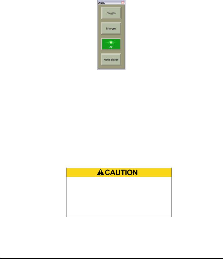
Auxiliary Functions
TheAuxiliary Functions Control Bar contains buttons for manually activating assist gas flow and the fume blower system.
Open/close this control bar by selecting the “Aux.” button on the Operator Console Control Bar, or by selecting View |
Control Bars | Aux.
Oxygen: This control is both a manual activation button and indicator for oxygen assist gas. When executing a cutting program, the control automatically commands assist gas flow through the nozzle. When oxygen assist gas is flowing, the “Oxygen” indicator color changes from dull green or gray (OFF) to bright green (ON). This button is used in Jog or Auto mode to manually control the oxygen assist gas solenoid valve.
Nitrogen: This control is both a manual activation button and indicator for nitrogen assist gas. When nitrogen assist gas is flowing, the “Nitrogen” indicator color changes from dull green or gray (OFF) to bright green (ON).This button is used in Jog or Auto mode to manually control the nitrogen assist gas solenoid valve.
Air: This control is both a manual activation button and indicator for air assist gas.When air assist gas is flowing, the “Air” indicator color changes from dull green or gray (OFF) to bright green (ON). This button is used in Jog or Auto mode to manually control the air assist gas solenoid valve.
Note: Only one assist gas can be active at a time. If nitrogen is flowing when the oxygen button is selected, the nitrogen gas solenoid will close and the oxygen gas solenoid will open, etc.
Verify correct installation of lens drawer and nozzle tip before activating either assist gas solenoid valve. Applying assist gas pressure without proper installation of these parts can force the lens drawer or nozzle tip out of position or out of the cutting head. Unrestricted flow can also damage assist gas supply components.
Fume Blower: This a manual activation button and indicator for the fume blower. Selecting this button toggles the fume blower on or off when the program is not running. The fume blower turns on automatically when the machine is cutting.
When the program ends, the fume blower remains on for 60 seconds, plus the Blower OFF delay time specified on the
Auxiliary page of the Configuration window, and then turns off automatically. This button is used to provide additional fume removal time. The “Fume Blower” indicator color is dull green or gray (OFF) when the fume blower is off and bright green (ON) when the fume blower is running.
7-13 |
EM-551 (N-04/11) |
Menu Commands
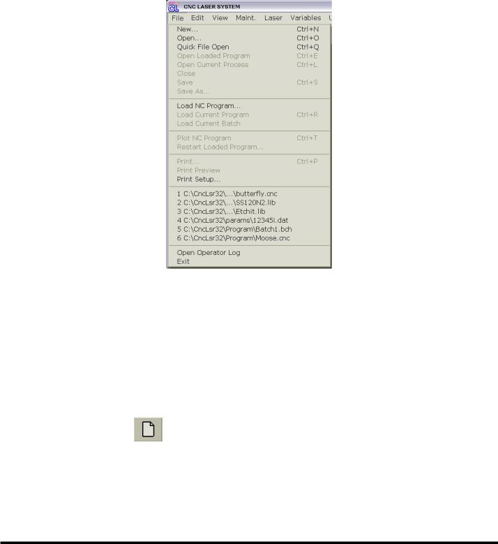
File Menu
In the File menu, various commands can be used to manage files and to activate file-related functions. Many of the File menu commands, such as Open, Save, and Print, are standard commands used by most Microsoft Windows applications, while others are for Laser System-specific functions: Open Current Process, Load Current Program, etc.
NEW
File | New creates a new file and opens a new window displaying the files contents. The Laser System software works with three different types of data files (see FILE TYPES). Before a new file is generated, the ‘New File’dialog box opens, prompting the user to specify the type of file to create. The following types of file can be created::
•NC Program File
•Process Parameter File
•Batch Program File
Toolbar Shortcut: |
|
Keyboard Shortcut: |
Ctrl + N or { Alt, F, N } sequence |
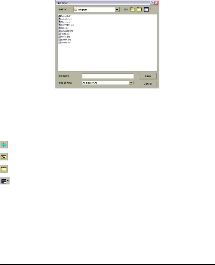
OPEN
File | Open opens an existing laser file in a new window. Multiple file windows of all types can be open at the same time. This command causes the File Open window to appear. Use this window to select a file to open.
EM-551 (N-04/11) |
7-14 |
Note: Use the Most Recently Used (MRU) File List to quickly reopen a file that was recently closed. See the MRU FILE LIST section for more information.
Use these controls in the File Open window to identify the file to be opened:
Look In: Displays the name of the folder whose contents are displayed in the browser box below. To see how the current folder fits in the folder hierarchy, select the down arrow. To see what is inside a folder, select the folder.
File Browser: This is the large box below the “Look In” field that lists the folders and files in the folder specified in the “Look In” field. Use the browser to graphically select a file or a different folder. Double-clicking a folder will cause its contents to be displayed in the browser and its name to appear in the “Look In” field. The buttons above the browser window can be used to find and select folders and files:
Navigate the browser to the previously selected folder.
Navigate the browser to the folder one level higher than the currently displayed folder.
Create a new folder.
Change the browser view mode.
File name: Type the name of the file to be opened here or use the browser window to graphically select the file to open. Selecting a file in the browser window will cause its name to appear in the “File name” field.
Files of type: Lists the types of files to display in the browser. The choices are:
•All Files
•NC Program File (with .cnc extension)
•Process Parameter Files (with .lib extension)
•Batch Files (with .bch extension)
Note: Only files with the extension listed in the “Files of Type” drop-down list are shown in the browser window.
7-15 |
EM-551 (N-04/11) |
Toolbar Shortcut: |
|
Keyboard Shortcut: |
Ctrl + O or { Alt, F, O } sequence |
QUICK FILE OPEN
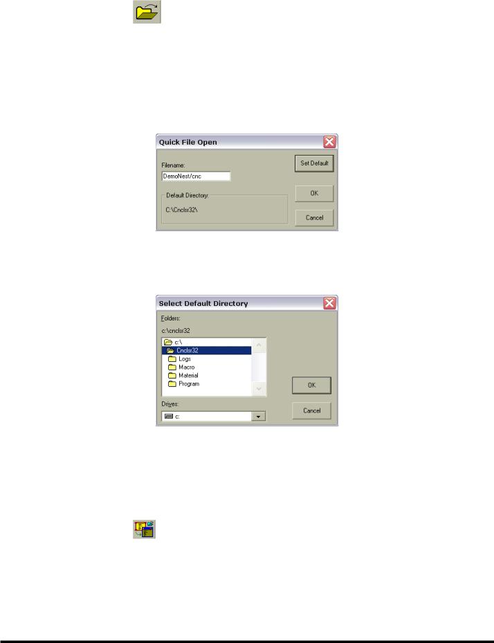
File | Quick File Open opens existing NC Program, Process Parameter, or Batch Program files. The Quick File Open command will display the Quick File Open window.The name of the file to be opened is typed in the “Filename” field.The file must be located in the directory indicated in the ‘Default Directory’box.
The “OK” button will open the file specified and close the Quick File Open window. The “Cancel” button will close the Quick File Open window without opening a file. The “Set Default” button will open the Select Default Directory window that will allow the user to select a new default directory. Once selected, this default directory will be saved and used until a new selection is made.
Keyboard Shortcut: |
Ctrl + Q or { Alt, F, Q } sequence |
OPEN LOADED PROGRAM
File | Open Loaded Program opens a window displaying the NC Program file currently loaded for execution. If no cutting program is currently loaded, this command is disabled
Toolbar Shortcut: |
|
Keyboard Shortcut: |
Ctrl + E |
OPEN CURRENT PROCESS
File | Open Current Process opens a new window displaying the Process Parameter file currently being used for cutting.
If no cutting program is currently loaded for execution, this command is disabled.
EM-551 (N-04/11) |
7-16 |
Toolbar Shortcut: |
|
Keyboard Shortcut : |
Ctrl + L |
CLOSE
File | Close closes the active file. If the open file contains unsaved changes, the user will be prompted to save the changes before closing the file. If a file is closed that has not been named, the Save As window will open first, prompting the user to name the file before closing it.
Note: If a file is closed without saving it, all changes made since the last time the file was saved will be lost.
Keyboard Shortcut: Ctrl + F4 or { Alt, F, C } sequence “X” button on the window’s caption bar : 
SAVE
File | Save saves any changes to the active file.The contents of the file will be written to its current location with its current file name. When a new file is saved for the first time, the Save As window will open first, prompting the user to name the file.
Toolbar Shortcut: |
|
Keyboard Shortcut: |
Ctrl + S or { Alt, F, S } sequence |
SAVE AS
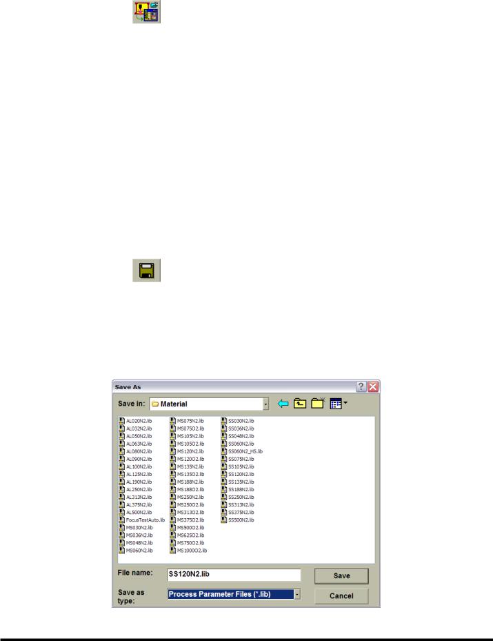
File | Save As saves a new file with the specified name, or saves the contents of the active file to a different name and/or location. This command causes the Save As window to open. Use this window to specify the file name and location.
Use these controls in the ‘SaveAs’dialog box to specify the name of the file and its location:
7-17 |
EM-551 (N-04/11) |
Save in: Displays the name of the folder whose contents are displayed in the browser box below it. To see how the current folder fits in the folder hierarchy, select the down arrow. To see what is inside a folder, select the folder.
File Browser: This is the large box below the “Save in” field that lists the folders and files in the folder specified in the “Save In” field. Use the browser to graphically select a file or a different folder. Double-clicking a folder will cause its contents to be displayed in the browser and its name to appear in the “Save in” field. The buttons above the browser window can be used to find and select folders and files:
Navigate the browser to the previously selected folder.
Navigate the browser to the folder one level higher than the currently displayed folder.
Create a new folder.
Change the browser view mode.
File name: Enter the file name here or use the browser window to graphically select an existing file name. Selecting a file in thebrowserwindowwillcauseitsnametoappearinthe“Filename”field.Ifthefilenameenteredherehasnoextension, the extension listed in the “Save as type” drop-down list will be automatically added to the file name when it is saved.
Save as type: Specifies the type of file being saved. The list automatically includes the file type corresponding to the document in the active window as the default type. For example, if the active window is a Process Parameter file, the box will list “Process Parameter Files (*.lib)” as the file type.
Note: Only files with the extension listed in the “Files of Type” drop-down list are shown in the browser window.
Keyboard Shortcut: |
{ Alt, F, A } sequence |
LOAD NC PROGRAM
File | Load NC Program allows the user to specify an NC Program file to load into program execution memory. Each program must be loaded into memory before it can be run. Once a program is loaded, it can be run multiple times without being loaded again. Note that only one program can be loaded at a time. This command opens the Load NC Program to Execute window, from which box to select a file to load. The Load NC Program to Execute window is similar to the window used to open a file. See the OPEN topic in the FILE section for help with using this window.
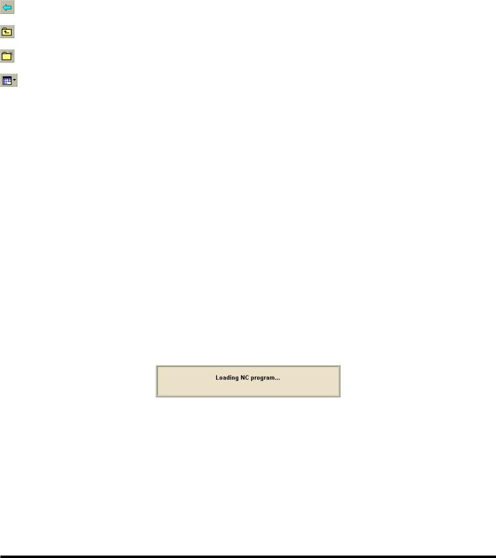
Some very large cutting programs may require several seconds to load. The following message window will be displayed while the control is busy loading a program:
Note: The Laser System user interface is disabled until the control finishes loading the program.
Keyboard Shortcut: |
{ Alt, F, L } sequence |
LOAD CURRENT PROGRAM
File | Load Current Program loads the NC Program in the currently active Program Edit window into program execution memory. This command is enabled only when an NC Program file is open in the currently active window. Each program must be loaded into memory before it can be run. Once a program is loaded, it can be run multiple times without being loaded again. Note that only one program can be loaded at a time.
Some very large cutting programs may require several seconds to load. The following message window will be displayed
EM-551 (N-04/11) |
7-18 |
while the control is busy loading a program:
Note: The Laser System user interface is disabled until the control finishes loading the program.
Toolbar Shortcut: |
|
Keyboard Shortcut: |
Ctrl + R |
LOAD CURRENT BATCH
File | Load Current Batch loads the currently open Batch Program file for execution. This command is enabled only when a Batch Program file is open in the currently active window. See the BATCH PROGRAM FILE topic in the FILES TYPES section for more about Batch Program files.
PLOT NC PROGRAMS
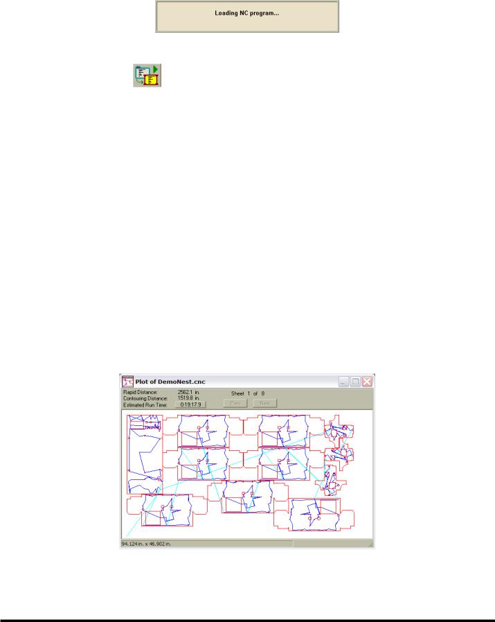
When the active window is an NC Program Edit window, the File | Plot NC Program command can be used to display a graphical plot of the cutting program, one sheet at a time.
If the program has no syntax errors, this command will open a new Program Plot window showing the programmed tool path. The plot represents where the cutting head would move if the operator ran the program. If the program has a syntax error, selecting “Plot NC Program” will only display the error message, and the cursor in the Program Edit window will be positioned on the line containing the error.
The Program Plot window uses different colors to display two types of rapid traverse moves (light blue for Z-axis up and dark blue for Z-axis down), and two types of contouring moves (red for laser on and green for laser off). When the program uses more than one sheet, the “Next” and “Prev” buttons change the plot window to display another sheet. The plotting software interprets M50 in the program as the beginning of another sheet.
The top section of the Program Plot window displays the total Rapid Distance, Contouring Distance, and Estimated Run Time for each sheet. The estimated run time does not include time to exchange pallets (M50) or the effect of the Feedrate Override setting. The plotting function assumes that the pallets are in position and the machine is ready to run.
7-19 |
EM-551 (N-04/11) |

At the bottom of the Program Plot window, a status bar displays the overall X-axis and Y-axis dimensions of the cutting program.
To change the plot window magnification, use the Zoom functions (see WINDOW ZOOMING in the VIEW MENU section).
The Program Plot window can also display information about individual lines and arcs in a program. When the cursor is positioned on a line or arc, a small pop-up window displays the command type (G00, G01, G02, or G03) with the X and Y machine coordinates of the start and end. The pop-up window also displays the radius for a G02 or G03 arc.
Keyboard Shortcut: |
Ctrl + T |
RESTART LOADED PROGRAM
File | Restart Loaded Program activates the Program Restart function, which allows a program to be restarted at a specified line number. This function is intended for use when long programs are terminated before completion and the normal program recovery method cannot be used. Program Restart is particularly useful with the Automatic Laser Shutdown function (see Auto SHUT-DOWN, in the LASER MENU section), which will display the last absolute line number executed when a program has not run to completion.
Note: Restart Loaded Program will be enabled only if a program is loaded, the machine is in Auto mode, and is not currently running a program. At all other times, this menu command will appear grayed, indicating the Program Restart function is disabled.
When this command is selected, the Restart Loaded Program window will be displayed, prompting the user for an absolute line number to restart the program at.
Note: Absolute line numbers identify the sequential position of a row or block of code in a program file. This number is always relative to the first line in the program, and is not necessarily the same as the optional program line number,
“Nxxxxx”.
The absolute line number of a part program is displayed in the Main Status Bar when the program file is open in a Program Edit window, and that window is the active window. To determine the absolute line number corresponding to a given block in a program file, open the file, move the cursor to the desired block and observe the line number in the status bar.
Note: If any window other than a Program Edit window is the active window, the line number will not be displayed in
EM-551 (N-04/11) |
7-20 |
Loading...