


 Loading...
OPERATING MANUAL
for CINCINNATI
ARROW E/DART 500/750 (ERM) ARROW 500/750/1000/1250C (ERM) ARROW 1250/1500/2000 (ERD) VERTICAL MACHINING CENTERS with
ACRAMATIC 2100E CNC CONTROL Release 3.0
PUBLICATION NO. 91203809-001
IMPORTANT
Carefully read the instructions and safety precautions given in this manual. Do not attempt to operate this machine until you have thoroughly read and understood the material contained in this manual and all other applicable manuals.
At the time of writing, the book was completely up--to--date. However, due to continual improvements in design, it is possible that descriptions contained herein may vary to a slight extent from the system delivered to you. This merely implies that the system has been improved to better fulfill your requirements. You are encouraged to contact the nearest Cincinnati Machine representative for clarification.
Patents Notice
The machine and attachments and parts thereof illustrated and described in this book are manufactured under and protected by issued and pending British and Foreign Patents and copyright is reserved in any original design feature thereof and in the contents of this book and every part thereof.
Cincinnati Machine U.K. Limited
P.O. Box 505, Kingsbury Road, Birmingham, B24 0QU
1998 Cincinnati Machine, a Division of UNOVA Industrial Automation Systems, Inc.
Cincinnati Machine, CINCINNATI, DART, ARROW, SABRE, LANCER and HAWK are trademarks of Cincinnati Machine, a division of UNOVA Industrial Automation Systems, Inc.
ACRAMATIC is a trademark of Vickers E.S.D., Inc.
Printed in England -- EDITION 3 -- January 1999

|
|
|
|
|
FOREWORD |
|
WARNING 1 |
|
|
||||
|
|
|
||||
In order to |
clearly |
show |
The purpose of this manual is to provide the necessary information to |
|||
enable suitably experienced personnel, to operate the CINCINNATI |
||||||
details |
of |
this |
machine, |
|||
MACHINE ARROW E/DART (ERM) and ARROW (ERD/ERM) |
||||||
some |
covers, |
shields, |
||||
Vertical Machining Centers, when fitted with ACRAMATIC A2100 |
||||||
guards, barriers, devices or |
||||||
doors |
have either |
been |
control. |
|||
removed or |
shown |
in an |
Information contained in this manual is not warranted and is subject to |
|||
”open” |
position. All |
such |
||||
change without notice. |
||||||
protective |
components |
|||||
must be installed in posi- |
The manual has not been prepared to enable inexperienced personnel to |
|||||
tion before |
operating this |
|||||
operate the machine without further training. |
||||||
machine. |
|
|
|
|||
Failure |
to |
follow |
this |
The owner/user is responsible for the training of inexperienced |
||
instruction |
may |
result in |
personnel and for providing the background necessary for experienced |
|||
personal injury. |
|
|
personnel to safely operate these machines. |
|||
|
|
|
|
|
||
|
|
|
|
|
|
|
The chapter on general safety precautions should be observed at all times during machine operation and maintenance. Read this chapter before reading the remaining chapters in this manual and operating the
machine.
WARNING 2
CUTTING FLUIDS |
|
Any questions pertaining to the operation of the machine should be |
||||
|
directed to: |
|
||||
When soluble coolants are |
|
|||||
Field Service Department |
Cincinnati Machine |
|||||
used, it is important to en- |
||||||
sure |
that |
recommended |
Cincinnati Machine UK Limited, |
Marketing Company, |
||
concentration levels |
are |
P.O. Box 505, |
Cincinnati, |
|||
maintained. |
|
|
Kingsbury Road, |
Ohio 45209-9988 |
||
Failure |
to |
follow |
this |
Birmingham, B24 0QU |
USA. |
|
England |
|
|||||
instruction can cause corro- |
|
|||||
sion of safety critical parts, |
Tel: 0121-351-3821 |
Main Tel: (513) 841-8100 |
||||
resulting in machine dam- |
Fax: 0121-313-1184 |
Service Tel: (513) 841 3000 |
||||
age and/or serious personal |
|
Service Fax: (513) 841 8871 |
||||
injury. |
|
|
|
|
|
|
DANGER
HIGH VOLTAGE
Lethal voltages are present in the magnetics and electrical control cabinets when the MACHINE MAIN DISCONNECT is ’ON’. Current and voltage measurements should be attempted only by qualified electrical maintenance personnel.
Before working on any electrical circuits, turn the machine Main Disconnect Device ’OFF’ and lock It.
Capacitors in the Servo Drives require up to 20 minutes to completely discharge. Always verify that discharge is complete using a known working and calibrated voltmeter before commencing work on these units.
Unless expressly stated in applicable Cincinnati Machine documentation or by the appropriate Cincinnati Machine Field Service Representative, do NOT work with electrical power ’ON’. If such express statement of advice exists, working with electrical power ’ON’ should be performed by a Cincinnati Machine Field Service Representative. The customer and subsequent transferees must determine that any other person performing work with electrical power ’ON’ is trained and technically qualified.
Failure To Follow This Instruction May Result In Death Or Serious Personal Shock Injury.
-1

Table of Contents
Chapter 1 |
|
Safety Precautions . . . . . . . . . . . . . . . . . . . . . . . . . |
1-1 |
Important . . . . . . . . . . . . . . . . . . . . . . . . . . . . . . . . . . . . . . . . . . . . . . . . . . . . . . . . . . . |
1-1 |
General Safety Instructions And Considerations . . . . . . . . . . . . . . . . . . . . . . . . . . . . |
1-1 |
Personal Safety . . . . . . . . . . . . . . . . . . . . . . . . . . . . . . . . . . . . . . . . . . . . . . . . . . . |
1-1 |
Work Area Safety . . . . . . . . . . . . . . . . . . . . . . . . . . . . . . . . . . . . . . . . . . . . . . . . . |
1-2 |
Tool Safety . . . . . . . . . . . . . . . . . . . . . . . . . . . . . . . . . . . . . . . . . . . . . . . . . . . . . . |
1-2 |
Lifting And Carrying Safety . . . . . . . . . . . . . . . . . . . . . . . . . . . . . . . . . . . . . . . . . |
1-2 |
Installation And Relocation Safety . . . . . . . . . . . . . . . . . . . . . . . . . . . . . . . . . . . . |
1-3 |
Setup And Operation Safety . . . . . . . . . . . . . . . . . . . . . . . . . . . . . . . . . . . . . . . . . |
1-3 |
Maintenance Safety . . . . . . . . . . . . . . . . . . . . . . . . . . . . . . . . . . . . . . . . . . . . . . . |
1-4 |
Materials Used With This Product . . . . . . . . . . . . . . . . . . . . . . . . . . . . . . . . . . . . |
1-5 |
LIFTING DEVICES . . . . . . . . . . . . . . . . . . . . . . . . . . . . . . . . . . . . . . . . . . . . . . . . . . |
1-6 |
GENERAL . . . . . . . . . . . . . . . . . . . . . . . . . . . . . . . . . . . . . . . . . . . . . . . . . . . . . . |
1-6 |
EYEBOLTS . . . . . . . . . . . . . . . . . . . . . . . . . . . . . . . . . . . . . . . . . . . . . . . . . . . . . |
1-6 |
HOIST RINGS . . . . . . . . . . . . . . . . . . . . . . . . . . . . . . . . . . . . . . . . . . . . . . . . . . . |
1-8 |
SPREADER BARS AND LIFTING BEAMS . . . . . . . . . . . . . . . . . . . . . . . . . . . |
1-9 |
CHAIN . . . . . . . . . . . . . . . . . . . . . . . . . . . . . . . . . . . . . . . . . . . . . . . . . . . . . . . . . |
1-9 |
CABLE SLINGS . . . . . . . . . . . . . . . . . . . . . . . . . . . . . . . . . . . . . . . . . . . . . . . . . |
1-11 |
SYNTHETIC MATERIAL SLINGS . . . . . . . . . . . . . . . . . . . . . . . . . . . . . . . . . . |
1-12 |
P TYPE HOOKS . . . . . . . . . . . . . . . . . . . . . . . . . . . . . . . . . . . . . . . . . . . . . . . . . |
1-13 |
S HOOKS . . . . . . . . . . . . . . . . . . . . . . . . . . . . . . . . . . . . . . . . . . . . . . . . . . . . . . . |
1-13 |
U TYPE HOOKS . . . . . . . . . . . . . . . . . . . . . . . . . . . . . . . . . . . . . . . . . . . . . . . . . |
1-15 |
GENERAL SAFETY LIFTING INFORMATION . . . . . . . . . . . . . . . . . . . . . . . . |
1-16 |
Fluids Used With Machine Tools . . . . . . . . . . . . . . . . . . . . . . . . . . . . . . . . . . . . . . . . |
1-17 |
General Considerations . . . . . . . . . . . . . . . . . . . . . . . . . . . . . . . . . . . . . . . . . . . . . |
1-17 |
Lubricants . . . . . . . . . . . . . . . . . . . . . . . . . . . . . . . . . . . . . . . . . . . . . . . . . . . . . . . |
1-17 |
Cutting Fluids . . . . . . . . . . . . . . . . . . . . . . . . . . . . . . . . . . . . . . . . . . . . . . . . . . . . |
1-17 |
Sources Of Information - USA . . . . . . . . . . . . . . . . . . . . . . . . . . . . . . . . . . . . . . |
1-17 |
Usage Information . . . . . . . . . . . . . . . . . . . . . . . . . . . . . . . . . . . . . . . . . . . . . . . . |
1-18 |
Cutting Fluids - Preventative Maintenance . . . . . . . . . . . . . . . . . . . . . . . . . . . . . . . . |
1-19 |
See Cautions 1 and 2 . . . . . . . . . . . . . . . . . . . . . . . . . . . . . . . . . . . . . . . . . . . . . . . |
1-19 |
Water Quality . . . . . . . . . . . . . . . . . . . . . . . . . . . . . . . . . . . . . . . . . . . . . . . . . . . . |
1-19 |
Too Soft . . . . . . . . . . . . . . . . . . . . . . . . . . . . . . . . . . . . . . . . . . . . . . . . . . . . . . . . . |
1-19 |
Too Hard . . . . . . . . . . . . . . . . . . . . . . . . . . . . . . . . . . . . . . . . . . . . . . . . . . . . . . . . |
1-19 |
Cleaning The Coolant Reservoir . . . . . . . . . . . . . . . . . . . . . . . . . . . . . . . . . . . . . . |
1-19 |
Lifespan . . . . . . . . . . . . . . . . . . . . . . . . . . . . . . . . . . . . . . . . . . . . . . . . . . . . . . . . . |
1-20 |
Tramp Oil . . . . . . . . . . . . . . . . . . . . . . . . . . . . . . . . . . . . . . . . . . . . . . . . . . . . . . . |
1-20 |
Filtering . . . . . . . . . . . . . . . . . . . . . . . . . . . . . . . . . . . . . . . . . . . . . . . . . . . . . . . . . |
1-20 |
Rust Prevention . . . . . . . . . . . . . . . . . . . . . . . . . . . . . . . . . . . . . . . . . . . . . . . . . . . |
1-20 |
Printed Circuit Board Handling Instructions . . . . . . . . . . . . . . . . . . . . . . . . . . . . . . . . |
1-21 |
General . . . . . . . . . . . . . . . . . . . . . . . . . . . . . . . . . . . . . . . . . . . . . . . . . . . . . . . . . |
1-21 |
Recommended Handling Procedure . . . . . . . . . . . . . . . . . . . . . . . . . . . . . . . . . . . |
1-21 |
Safety Features . . . . . . . . . . . . . . . . . . . . . . . . . . . . . . . . . . . . . . . . . . . . . . . . . . . . . . |
1-22 |
Perimeter Guarding . . . . . . . . . . . . . . . . . . . . . . . . . . . . . . . . . . . . . . . . . . . . . . . . |
1-22 |
Operator Sliding Door(s) . . . . . . . . . . . . . . . . . . . . . . . . . . . . . . . . . . . . . . . . . . . |
1-22 |

Table of Contents
Feed Hold Push Button . . . . . . . . . . . . . . . . . . . . . . . . . . . . . . . . . . . . . . . . . . . . . |
1-22 |
Emergency Stop Push Button . . . . . . . . . . . . . . . . . . . . . . . . . . . . . . . . . . . . . . . . |
1-22 |
Electrical Isolation Device . . . . . . . . . . . . . . . . . . . . . . . . . . . . . . . . . . . . . . . . . . |
1-23 |
Air Supply Isolation Valve . . . . . . . . . . . . . . . . . . . . . . . . . . . . . . . . . . . . . . . . . . |
1-23 |
Metric Lifting Points . . . . . . . . . . . . . . . . . . . . . . . . . . . . . . . . . . . . . . . . . . . . . . . |
1-23 |
Machine Related Safety And Usage Notes . . . . . . . . . . . . . . . . . . . . . . . . . . . . . . . . . |
1-23 |
Axis Overtravel Condition . . . . . . . . . . . . . . . . . . . . . . . . . . . . . . . . . . . . . . . . . . |
1-23 |
Through Spindle Coolant Option . . . . . . . . . . . . . . . . . . . . . . . . . . . . . . . . . . . . . |
1-23 |
Tooling Taper - Spindle . . . . . . . . . . . . . . . . . . . . . . . . . . . . . . . . . . . . . . . . . . . . |
1-23 |
Inter-drilled Tooling . . . . . . . . . . . . . . . . . . . . . . . . . . . . . . . . . . . . . . . . . . . . . . . |
1-23 |
Drive Key Spindle Unit . . . . . . . . . . . . . . . . . . . . . . . . . . . . . . . . . . . . . . . . . . . . |
1-23 |
Safe Operation Of Multi-part Tooling . . . . . . . . . . . . . . . . . . . . . . . . . . . . . . . . . |
1-24 |
Tool Drum Positioning . . . . . . . . . . . . . . . . . . . . . . . . . . . . . . . . . . . . . . . . . . . . . |
1-24 |
Tool Storage Drum . . . . . . . . . . . . . . . . . . . . . . . . . . . . . . . . . . . . . . . . . . . . . . . . |
1-24 |
Tool Storage Drum - Pocket Wear . . . . . . . . . . . . . . . . . . . . . . . . . . . . . . . . . . . . |
1-24 |
Loading Tools into Spindle . . . . . . . . . . . . . . . . . . . . . . . . . . . . . . . . . . . . . . . . . . |
1-24 |
Loading Tools into Storage Drum Pockets . . . . . . . . . . . . . . . . . . . . . . . . . . . . . . |
1-24 |
Levelling . . . . . . . . . . . . . . . . . . . . . . . . . . . . . . . . . . . . . . . . . . . . . . . . . . . . . . . . |
1-24 |
Bolting to Foundation . . . . . . . . . . . . . . . . . . . . . . . . . . . . . . . . . . . . . . . . . . . . . . |
1-24 |
Lithium Batteries . . . . . . . . . . . . . . . . . . . . . . . . . . . . . . . . . . . . . . . . . . . . . . . . . |
1-25 |
Chapter 2 |
|
System Information . . . . . . . . . . . . . . . . . . . . . . . . |
2-1 |
Introduction . . . . . . . . . . . . . . . . . . . . . . . . . . . . . . . . . . . . . . . . . . . . . . . . . . . . . . . . . |
2-1 |
Machine Information . . . . . . . . . . . . . . . . . . . . . . . . . . . . . . . . . . . . . . . . . . . . . . . . . . |
2-2 |
Machine Location . . . . . . . . . . . . . . . . . . . . . . . . . . . . . . . . . . . . . . . . . . . . . . . . . |
2-3 |
EMC Directive Requirements . . . . . . . . . . . . . . . . . . . . . . . . . . . . . . . . . . . . . . . . |
2-3 |
NC Control . . . . . . . . . . . . . . . . . . . . . . . . . . . . . . . . . . . . . . . . . . . . . . . . . . . . . . |
2-3 |
Axis Orientation . . . . . . . . . . . . . . . . . . . . . . . . . . . . . . . . . . . . . . . . . . . . . . . . . . |
2-4 |
Guard Strength . . . . . . . . . . . . . . . . . . . . . . . . . . . . . . . . . . . . . . . . . . . . . . . . . . . |
2-5 |
Noise . . . . . . . . . . . . . . . . . . . . . . . . . . . . . . . . . . . . . . . . . . . . . . . . . . . . . . . . . . . |
2-5 |
Work-piece/Work Holding Device Loading/Unloading . . . . . . . . . . . . . . . . . . . . |
2-6 |
Fumes And Coolant Misting . . . . . . . . . . . . . . . . . . . . . . . . . . . . . . . . . . . . . . . . . |
2-6 |
Fire Hazard . . . . . . . . . . . . . . . . . . . . . . . . . . . . . . . . . . . . . . . . . . . . . . . . . . . . . . |
2-6 |
Arrow E/Dart (ERM) Specification . . . . . . . . . . . . . . . . . . . . . . . . . . . . . . . . . . . . . . . |
2-7 |
Arrow (ERM) Specification . . . . . . . . . . . . . . . . . . . . . . . . . . . . . . . . . . . . . . . . . . . . |
2-9 |
Arrow (ERD) Specification . . . . . . . . . . . . . . . . . . . . . . . . . . . . . . . . . . . . . . . . . . . . . |
2-13 |
DART/ARROW (ERM)Table Dimensions . . . . . . . . . . . . . . . . . . . . . . . . . . . . . . |
2-19 |
ARROW (ERD)Table Dimensions . . . . . . . . . . . . . . . . . . . . . . . . . . . . . . . . . . . . |
2-23 |
Tool Holder And Retention Stud . . . . . . . . . . . . . . . . . . . . . . . . . . . . . . . . . . . . . . . . . |
2-24 |
JMTBA-BT Tool Holder And Retention Stud . . . . . . . . . . . . . . . . . . . . . . . . . . . . . . |
2-25 |
Motor Rating . . . . . . . . . . . . . . . . . . . . . . . . . . . . . . . . . . . . . . . . . . . . . . . . . . . . . . . . |
2-26 |
6000rpm. Spindle |
|
Arrow E/Dart Machine - Standard Speed Range . . . . . . . . . . . . . . . . . . . . . . |
2-27 |
6000rpm. Spindle |
|
Arrow Machine - Standard Speed Range . . . . . . . . . . . . . . . . . . . . . . . . . . . |
2-28 |
8000rpm. Spindle Speed Range |
|
Arrow Machine . . . . . . . . . . . . . . . . . . . . . . . . . . . . . . . . . . . . . . . . . . . . . . . . |
2-29 |

Table of Contents
10,000rpm. Spindle Speed Range |
|
Arrow Machine . . . . . . . . . . . . . . . . . . . . . . . . . . . . . . . . . . . . . . . . . . . . . . . . |
2-30 |
5000rpm. Spindle |
|
Arrow Machine - High Torque Speed Range . . . . . . . . . . . . . . . . . . . . . . . . |
2-31 |
Chapter 3 |
|
Control Introduction . . . . . . . . . . . . . . . . . . . . . . . . |
3-1 |
Operator Station . . . . . . . . . . . . . . . . . . . . . . . . . . . . . . . . . . . . . . . . . . . . . . . . . . . . . |
3-2 |
Operator Station Assembly (OSA) Keypad . . . . . . . . . . . . . . . . . . . . . . . . . . . . . |
3-3 |
Machine On . . . . . . . . . . . . . . . . . . . . . . . . . . . . . . . . . . . . . . . . . . . . . . . . . . . . . . |
3-3 |
Machine Off . . . . . . . . . . . . . . . . . . . . . . . . . . . . . . . . . . . . . . . . . . . . . . . . . . . . . |
3-4 |
Emergency Stop . . . . . . . . . . . . . . . . . . . . . . . . . . . . . . . . . . . . . . . . . . . . . . . . . . |
3-4 |
Page And Position keys . . . . . . . . . . . . . . . . . . . . . . . . . . . . . . . . . . . . . . . . . . . . |
3-4 |
Numeric Keys . . . . . . . . . . . . . . . . . . . . . . . . . . . . . . . . . . . . . . . . . . . . . . . . . . . . |
3-4 |
Escape, Help, Control, Alternate . . . . . . . . . . . . . . . . . . . . . . . . . . . . . . . . . . . . . |
3-5 |
The Control Screen . . . . . . . . . . . . . . . . . . . . . . . . . . . . . . . . . . . . . . . . . . . . . . . . . . . |
3-6 |
Display Areas . . . . . . . . . . . . . . . . . . . . . . . . . . . . . . . . . . . . . . . . . . . . . . . . . . . . |
3-6 |
How Menu Buttons Function . . . . . . . . . . . . . . . . . . . . . . . . . . . . . . . . . . . . . . . . |
3-7 |
Production Menu Display . . . . . . . . . . . . . . . . . . . . . . . . . . . . . . . . . . . . . . . . . . . |
3-8 |
Current Menu Display . . . . . . . . . . . . . . . . . . . . . . . . . . . . . . . . . . . . . . . . . . . . . |
3-8 |
Status Bar . . . . . . . . . . . . . . . . . . . . . . . . . . . . . . . . . . . . . . . . . . . . . . . . . . . . . . . |
3-8 |
General Mode Button Bar . . . . . . . . . . . . . . . . . . . . . . . . . . . . . . . . . . . . . . . . . . . . . . |
3-8 |
Machine . . . . . . . . . . . . . . . . . . . . . . . . . . . . . . . . . . . . . . . . . . . . . . . . . . . . . . . . . |
3-9 |
Edit . . . . . . . . . . . . . . . . . . . . . . . . . . . . . . . . . . . . . . . . . . . . . . . . . . . . . . . . . . . . |
3-9 |
RAP (Resident Assistant Programmer) . . . . . . . . . . . . . . . . . . . . . . . . . . . . . . . . |
3-13 |
SFP (Shop Floor Programming) . . . . . . . . . . . . . . . . . . . . . . . . . . . . . . . . . . . . . . |
3-16 |
Tools . . . . . . . . . . . . . . . . . . . . . . . . . . . . . . . . . . . . . . . . . . . . . . . . . . . . . . . . . . . |
3-16 |
Multi-Setup . . . . . . . . . . . . . . . . . . . . . . . . . . . . . . . . . . . . . . . . . . . . . . . . . . . . . |
3-17 |
More (Additional Mode Selections) . . . . . . . . . . . . . . . . . . . . . . . . . . . . . . . . . . . |
3-18 |
Diagnostics . . . . . . . . . . . . . . . . . . . . . . . . . . . . . . . . . . . . . . . . . . . . . . . . . . . . . . |
3-19 |
Service . . . . . . . . . . . . . . . . . . . . . . . . . . . . . . . . . . . . . . . . . . . . . . . . . . . . . . . . . . |
3-20 |
System Configuration . . . . . . . . . . . . . . . . . . . . . . . . . . . . . . . . . . . . . . . . . . . . . |
3-21 |
File Manager . . . . . . . . . . . . . . . . . . . . . . . . . . . . . . . . . . . . . . . . . . . . . . . . . . . . . |
3-22 |
Mode Specific Button Bar . . . . . . . . . . . . . . . . . . . . . . . . . . . . . . . . . . . . . . . . . . . . . . |
3-22 |
Back . . . . . . . . . . . . . . . . . . . . . . . . . . . . . . . . . . . . . . . . . . . . . . . . . . . . . . . . . . . |
3-22 |
Display . . . . . . . . . . . . . . . . . . . . . . . . . . . . . . . . . . . . . . . . . . . . . . . . . . . . . . . . . |
3-22 |
Home . . . . . . . . . . . . . . . . . . . . . . . . . . . . . . . . . . . . . . . . . . . . . . . . . . . . . . . . . . . |
3-22 |
Touch Screen and Keyboards . . . . . . . . . . . . . . . . . . . . . . . . . . . . . . . . . . . . . . . . |
3-23 |
Plotter Display . . . . . . . . . . . . . . . . . . . . . . . . . . . . . . . . . . . . . . . . . . . . . . . . . . . |
3-24 |
Help Information . . . . . . . . . . . . . . . . . . . . . . . . . . . . . . . . . . . . . . . . . . . . . . . . . . |
3-25 |
Machine Mode . . . . . . . . . . . . . . . . . . . . . . . . . . . . . . . . . . . . . . . . . . . . . . . . . . . . . . . |
3-26 |
Display Groups buttons . . . . . . . . . . . . . . . . . . . . . . . . . . . . . . . . . . . . . . . . . . . . |
3-26 |
Menus . . . . . . . . . . . . . . . . . . . . . . . . . . . . . . . . . . . . . . . . . . . . . . . . . . . . . . . . . . |
3-26 |
Axis Displays . . . . . . . . . . . . . . . . . . . . . . . . . . . . . . . . . . . . . . . . . . . . . . . . . . . . . . . |
3-27 |
Current . . . . . . . . . . . . . . . . . . . . . . . . . . . . . . . . . . . . . . . . . . . . . . . . . . . . . . . . . |
3-27 |
To Go . . . . . . . . . . . . . . . . . . . . . . . . . . . . . . . . . . . . . . . . . . . . . . . . . . . . . . . . . . |
3-27 |
4-View . . . . . . . . . . . . . . . . . . . . . . . . . . . . . . . . . . . . . . . . . . . . . . . . . . . . . . . . . |
3-27 |

Table of Contents
Limits . . . . . . . . . . . . . . . . . . . . . . . . . . . . . . . . . . . . . . . . . . . . . . . . . . . . . . . . . . |
3-27 |
Servo . . . . . . . . . . . . . . . . . . . . . . . . . . . . . . . . . . . . . . . . . . . . . . . . . . . . . . . . . . . |
3-27 |
Servo Setup . . . . . . . . . . . . . . . . . . . . . . . . . . . . . . . . . . . . . . . . . . . . . . . . . . . . . . |
3-27 |
Program Debug . . . . . . . . . . . . . . . . . . . . . . . . . . . . . . . . . . . . . . . . . . . . . . . . . . . |
3-27 |
Offset Displays . . . . . . . . . . . . . . . . . . . . . . . . . . . . . . . . . . . . . . . . . . . . . . . . . . . . . . |
3-28 |
Pallet Offsets Display . . . . . . . . . . . . . . . . . . . . . . . . . . . . . . . . . . . . . . . . . . . . . . |
3-28 |
Multi Setup Offsets . . . . . . . . . . . . . . . . . . . . . . . . . . . . . . . . . . . . . . . . . . . . . . . . |
3-28 |
Fixture Offsets . . . . . . . . . . . . . . . . . . . . . . . . . . . . . . . . . . . . . . . . . . . . . . . . . . . |
3-28 |
Prog. Coord Offsets . . . . . . . . . . . . . . . . . . . . . . . . . . . . . . . . . . . . . . . . . . . . . . . |
3-28 |
Prog. Tool Offsets . . . . . . . . . . . . . . . . . . . . . . . . . . . . . . . . . . . . . . . . . . . . . . . . . |
3-28 |
Machine Offsets . . . . . . . . . . . . . . . . . . . . . . . . . . . . . . . . . . . . . . . . . . . . . . . . . . |
3-28 |
Other Displays . . . . . . . . . . . . . . . . . . . . . . . . . . . . . . . . . . . . . . . . . . . . . . . . . . . . . . . |
3-29 |
Program Display . . . . . . . . . . . . . . . . . . . . . . . . . . . . . . . . . . . . . . . . . . . . . . . . . . |
3-29 |
Message . . . . . . . . . . . . . . . . . . . . . . . . . . . . . . . . . . . . . . . . . . . . . . . . . . . . . . . . . |
3-29 |
System Registers . . . . . . . . . . . . . . . . . . . . . . . . . . . . . . . . . . . . . . . . . . . . . . . . . . |
3-29 |
Variables Display . . . . . . . . . . . . . . . . . . . . . . . . . . . . . . . . . . . . . . . . . . . . . . . . . |
3-29 |
View Drawing Display . . . . . . . . . . . . . . . . . . . . . . . . . . . . . . . . . . . . . . . . . . . . . |
3-29 |
Plotter Display . . . . . . . . . . . . . . . . . . . . . . . . . . . . . . . . . . . . . . . . . . . . . . . . . . . |
3-29 |
Cycle Parameters . . . . . . . . . . . . . . . . . . . . . . . . . . . . . . . . . . . . . . . . . . . . . . . . . |
3-29 |
Program Parameters . . . . . . . . . . . . . . . . . . . . . . . . . . . . . . . . . . . . . . . . . . . . . . . |
3-29 |
Process Control Data Display . . . . . . . . . . . . . . . . . . . . . . . . . . . . . . . . . . . . . . . . |
3-30 |
Tables - General . . . . . . . . . . . . . . . . . . . . . . . . . . . . . . . . . . . . . . . . . . . . . . . . . . |
3-30 |
Coordinate Offsets . . . . . . . . . . . . . . . . . . . . . . . . . . . . . . . . . . . . . . . . . . . . . . . . . . . . |
3-31 |
Coordinate Offset Types . . . . . . . . . . . . . . . . . . . . . . . . . . . . . . . . . . . . . . . . . . . . |
3-31 |
Words and Codes Associated with Offsets . . . . . . . . . . . . . . . . . . . . . . . . . . . . . . |
3-32 |
Entering Values to Offset Tables . . . . . . . . . . . . . . . . . . . . . . . . . . . . . . . . . . . . . . |
3-32 |
Pallet Offsets . . . . . . . . . . . . . . . . . . . . . . . . . . . . . . . . . . . . . . . . . . . . . . . . . . . . . |
3-33 |
Basic Procedure for Setting Pallet Offsets . . . . . . . . . . . . . . . . . . . . . . . . . . . . . . |
3-33 |
Alternative Method for Setting Pallet Offsets . . . . . . . . . . . . . . . . . . . . . . . . . . . |
3-34 |
Multiple Setup Offsets . . . . . . . . . . . . . . . . . . . . . . . . . . . . . . . . . . . . . . . . . . . . . |
3-35 |
Basic Procedure for Setting Multiple Setup Offsets . . . . . . . . . . . . . . . . . . . . . . . |
3-35 |
Alternative Method for Setting Multi-Setup Offsets . . . . . . . . . . . . . . . . . . . . . . |
3-36 |
Fixture Offsets (H word) . . . . . . . . . . . . . . . . . . . . . . . . . . . . . . . . . . . . . . . . . . . . |
3-37 |
Basic Procedure for Setting Fixture Offsets . . . . . . . . . . . . . . . . . . . . . . . . . . . . . |
3-37 |
NC Program Offsets (D word) . . . . . . . . . . . . . . . . . . . . . . . . . . . . . . . . . . . . . . . |
3-39 |
Combining Offsets . . . . . . . . . . . . . . . . . . . . . . . . . . . . . . . . . . . . . . . . . . . . . . . . |
3-40 |
Offset Table Field Descriptions . . . . . . . . . . . . . . . . . . . . . . . . . . . . . . . . . . . . . . |
3-41 |
Select Table Display Buttons . . . . . . . . . . . . . . . . . . . . . . . . . . . . . . . . . . . . . . . . |
3-41 |
Pallet Offset Table Definitions . . . . . . . . . . . . . . . . . . . . . . . . . . . . . . . . . . . . . . . |
3-42 |
Multi-Setup Offset Table Definitions . . . . . . . . . . . . . . . . . . . . . . . . . . . . . . . . . . |
3-43 |
Fixture Offset Table Definitions . . . . . . . . . . . . . . . . . . . . . . . . . . . . . . . . . . . . . . |
3-43 |
NC Program Offset Table Definitions . . . . . . . . . . . . . . . . . . . . . . . . . . . . . . . . . |
3-43 |
Tool Mode . . . . . . . . . . . . . . . . . . . . . . . . . . . . . . . . . . . . . . . . . . . . . . . . . . . . . . . . . . |
3-44 |
Active Tool Set . . . . . . . . . . . . . . . . . . . . . . . . . . . . . . . . . . . . . . . . . . . . . . . . . . . |
3-45 |
Tool File . . . . . . . . . . . . . . . . . . . . . . . . . . . . . . . . . . . . . . . . . . . . . . . . . . . . . . . . |
3-45 |
Tool Loading and Unloading . . . . . . . . . . . . . . . . . . . . . . . . . . . . . . . . . . . . . . . . |
3-45 |
Tool Table Display Fields . . . . . . . . . . . . . . . . . . . . . . . . . . . . . . . . . . . . . . . . . . . |
3-46 |

Table of Contents
Serial Number . . . . . . . . . . . . . . . . . . . . . . . . . . . . . . . . . . . . . . . . . . . . . . . . . . . . |
3-46 |
Tool Handling . . . . . . . . . . . . . . . . . . . . . . . . . . . . . . . . . . . . . . . . . . . . . . . . . . . . |
3-46 |
Tool Geometry . . . . . . . . . . . . . . . . . . . . . . . . . . . . . . . . . . . . . . . . . . . . . . . . . . . |
3-46 |
Tool Setup and Usage . . . . . . . . . . . . . . . . . . . . . . . . . . . . . . . . . . . . . . . . . . . . . . |
3-46 |
Tool History . . . . . . . . . . . . . . . . . . . . . . . . . . . . . . . . . . . . . . . . . . . . . . . . . . . . . |
3-47 |
Tool Sort By . . . . . . . . . . . . . . . . . . . . . . . . . . . . . . . . . . . . . . . . . . . . . . . . . . . . . |
3-47 |
Single . . . . . . . . . . . . . . . . . . . . . . . . . . . . . . . . . . . . . . . . . . . . . . . . . . . . . . . . . . |
3-47 |
Tool Magazine . . . . . . . . . . . . . . . . . . . . . . . . . . . . . . . . . . . . . . . . . . . . . . . . . . . |
3-48 |
Inch/Metric Selection . . . . . . . . . . . . . . . . . . . . . . . . . . . . . . . . . . . . . . . . . . . . . . |
3-48 |
Program Management . . . . . . . . . . . . . . . . . . . . . . . . . . . . . . . . . . . . . . . . . . . . . . . . . |
3-49 |
Directory Services (Registry, Import, Export) . . . . . . . . . . . . . . . . . . . . . . . . . . . |
3-49 |
Machine Pendant . . . . . . . . . . . . . . . . . . . . . . . . . . . . . . . . . . . . . . . . . . . . . . . . . . . . . |
3-51 |
Introduction . . . . . . . . . . . . . . . . . . . . . . . . . . . . . . . . . . . . . . . . . . . . . . . . . . . . . . |
3-53 |
Main Electrical Cabinet . . . . . . . . . . . . . . . . . . . . . . . . . . . . . . . . . . . . . . . . . . . . . . . . |
3-62 |
Optional Operating Devices . . . . . . . . . . . . . . . . . . . . . . . . . . . . . . . . . . . . . . . . . . . . |
3-63 |
Wash Gun . . . . . . . . . . . . . . . . . . . . . . . . . . . . . . . . . . . . . . . . . . . . . . . . . . . . . . . . . . |
3-63 |
Swarf Conveyor . . . . . . . . . . . . . . . . . . . . . . . . . . . . . . . . . . . . . . . . . . . . . . . . . . . . . . |
3-63 |
Emergency Stop - (Red Push Button with Latch) . . . . . . . . . . . . . . . . . . . . . . . . |
3-64 |
Swarf Conveyor Control - Auto/Manual - (Selector Switch) . . . . . . . . . . . . . . . |
3-64 |
Conveyor Direction - (Selector Switch, spring centred) . . . . . . . . . . . . . . . . . . . |
3-64 |
Swarf Management System (Swarf Wash) . . . . . . . . . . . . . . . . . . . . . . . . . . . . . . |
3-65 |
Chapter 4 |
|
|
General Setup Guide . . . . . . . . . . . . . . . . . . . . . . . |
4-1 |
|
Setup The Machine . . . . . . . . . . . . . . . . . . . . . . . . . . . . . . . . . . . . . . . . . . . . . . . . . . . |
4-1 |
|
Configure System . . . . . . . . . . . . . . . . . . . . . . . . . . . . . . . . . . . . . . . . . . . . . . . . . . . . |
4-1 |
|
Align Machine |
. . . . . . . . . . . . . . . . . . . . . . . . . . . . . . . . . . . . . . . . . . . . . . . . . . . . . . . |
4-2 |
Perform Operating Station Functions . . . . . . . . . . . . . . . . . . . . . . . . . . . . . . . . . . . . . |
4-2 |
|
Perform Operating Functions . . . . . . . . . . . . . . . . . . . . . . . . . . . . . . . . . . . . . . . . . . . |
4-2 |
|
Create Manual Data Input . . . . . . . . . . . . . . . . . . . . . . . . . . . . . . . . . . . . . . . . . . . . . . |
4-2 |
|
Set / Load Tooling . . . . . . . . . . . . . . . . . . . . . . . . . . . . . . . . . . . . . . . . . . . . . . . . . . . . |
4-3 |
|
Power Feed / Jog Axes . . . . . . . . . . . . . . . . . . . . . . . . . . . . . . . . . . . . . . . . . . . . . . . . |
4-3 |
|
Setup Part . . . . |
. . . . . . . . . . . . . . . . . . . . . . . . . . . . . . . . . . . . . . . . . . . . . . . . . . . . . . |
4-3 |
Set Tram Surface . . . . . . . . . . . . . . . . . . . . . . . . . . . . . . . . . . . . . . . . . . . . . . . . . . . . . |
4-4 |
|
Set Tool Lengths . . . . . . . . . . . . . . . . . . . . . . . . . . . . . . . . . . . . . . . . . . . . . . . . . . . . . |
4-4 |
|
Find A Program . . . . . . . . . . . . . . . . . . . . . . . . . . . . . . . . . . . . . . . . . . . . . . . . . . . . . . |
4-4 |
|
Load Part Program . . . . . . . . . . . . . . . . . . . . . . . . . . . . . . . . . . . . . . . . . . . . . . . . . . . . |
4-4 |
|
Create Part Program . . . . . . . . . . . . . . . . . . . . . . . . . . . . . . . . . . . . . . . . . . . . . . . . . . |
4-5 |
|
Edit Part Program . . . . . . . . . . . . . . . . . . . . . . . . . . . . . . . . . . . . . . . . . . . . . . . . . . . . |
4-5 |
|
Position Set . . . |
. . . . . . . . . . . . . . . . . . . . . . . . . . . . . . . . . . . . . . . . . . . . . . . . . . . . . . |
4-5 |
Create Multiple Setup . . . . . . . . . . . . . . . . . . . . . . . . . . . . . . . . . . . . . . . . . . . . . . . . . |
4-6 |
|
Copy Program . |
. . . . . . . . . . . . . . . . . . . . . . . . . . . . . . . . . . . . . . . . . . . . . . . . . . . . . . |
4-7 |
Plot Program . . |
. . . . . . . . . . . . . . . . . . . . . . . . . . . . . . . . . . . . . . . . . . . . . . . . . . . . . . |
4-7 |
Operating Checks . . . . . . . . . . . . . . . . . . . . . . . . . . . . . . . . . . . . . . . . . . . . . . . . . . . . |
4-7 |
|
Run a Part Program . . . . . . . . . . . . . . . . . . . . . . . . . . . . . . . . . . . . . . . . . . . . . . . . . . . |
4-8 |
|
How Do I... |
. . . . . . . . . . . . . . . . . . . . . . . . . . . . . . . . . . . . . |
4-9 |
Master Controls . . . . . . . . . . . . . . . . . . . . . . . . . . . . . . . . . . . . . . . . . . . . . . . . . . . . . . |
4-10 |
Switch On Power . . . . . . . . . . . . . . . . . . . . . . . . . . . . . . . . . . . . . . . . . . . . . . . . . |
4-10 |

Table of Contents
Switch-Off Power . . . . . . . . . . . . . . . . . . . . . . . . . . . . . . . . . . . . . . . . . . . . . . . . . |
4-11 |
Use Emergency Stop Push Button . . . . . . . . . . . . . . . . . . . . . . . . . . . . . . . . . . . . |
4-11 |
Machine Alignment . . . . . . . . . . . . . . . . . . . . . . . . . . . . . . . . . . . . . . . . . . . . . . . . . . . |
4-12 |
Align the Machine . . . . . . . . . . . . . . . . . . . . . . . . . . . . . . . . . . . . . . . . . . . . . . . . |
4-12 |
Axes Alignment Procedure . . . . . . . . . . . . . . . . . . . . . . . . . . . . . . . . . . . . . . . . . . |
4-12 |
Mechanism Alignment Procedure . . . . . . . . . . . . . . . . . . . . . . . . . . . . . . . . . . . . . |
4-13 |
Automatic Realignment . . . . . . . . . . . . . . . . . . . . . . . . . . . . . . . . . . . . . . . . . . . . |
4-14 |
Axes Functions . . . . . . . . . . . . . . . . . . . . . . . . . . . . . . . . . . . . . . . . . . . . . . . . . . . . . . |
4-15 |
Jog the X or Y Axis . . . . . . . . . . . . . . . . . . . . . . . . . . . . . . . . . . . . . . . . . . . . . . . |
4-15 |
Jog the Z, A, or B Axis . . . . . . . . . . . . . . . . . . . . . . . . . . . . . . . . . . . . . . . . . . . . . |
4-15 |
Power Feed the X or Y Axis . . . . . . . . . . . . . . . . . . . . . . . . . . . . . . . . . . . . . . . . . |
4-16 |
Power Feed the Z, A or B Axis . . . . . . . . . . . . . . . . . . . . . . . . . . . . . . . . . . . . . . |
4-16 |
Move an Axis with the Handwheel . . . . . . . . . . . . . . . . . . . . . . . . . . . . . . . . . . . . |
4-17 |
Override An Overtravel Limit . . . . . . . . . . . . . . . . . . . . . . . . . . . . . . . . . . . . . . . |
4-17 |
Jog Mechanisms . . . . . . . . . . . . . . . . . . . . . . . . . . . . . . . . . . . . . . . . . . . . . . . . . . |
4-18 |
Data Entry . . . . . . . . . . . . . . . . . . . . . . . . . . . . . . . . . . . . . . . . . . . . . . . . . . . . . . . . . . |
4-19 |
Keying In Data . . . . . . . . . . . . . . . . . . . . . . . . . . . . . . . . . . . . . . . . . . . . . . . . . . . |
4-19 |
Correcting Typing Mistakes . . . . . . . . . . . . . . . . . . . . . . . . . . . . . . . . . . . . . . . . . |
4-21 |
Select Text . . . . . . . . . . . . . . . . . . . . . . . . . . . . . . . . . . . . . . . . . . . . . . . . . . . . . . |
4-21 |
Perform Operator Station Keypad Operations . . . . . . . . . . . . . . . . . . . . . . . . . . . |
4-22 |
MDI Functions . . . . . . . . . . . . . . . . . . . . . . . . . . . . . . . . . . . . . . . . . . . . . . . . . . . . . . |
4-25 |
Create A Manual Data Input (MDI) Program . . . . . . . . . . . . . . . . . . . . . . . . . . . . |
4-25 |
Copy A MDI Program To Edit . . . . . . . . . . . . . . . . . . . . . . . . . . . . . . . . . . . . . . . |
4-25 |
Tool Functions . . . . . . . . . . . . . . . . . . . . . . . . . . . . . . . . . . . . . . . . . . . . . . . . . . . . . . . |
4-26 |
Display Tool Table Fields . . . . . . . . . . . . . . . . . . . . . . . . . . . . . . . . . . . . . . . . . . . |
4-26 |
Display Tool Sort . . . . . . . . . . . . . . . . . . . . . . . . . . . . . . . . . . . . . . . . . . . . . . . . . |
4-27 |
Display Single Tool . . . . . . . . . . . . . . . . . . . . . . . . . . . . . . . . . . . . . . . . . . . . . . . |
4-28 |
Display Tool Magazine . . . . . . . . . . . . . . . . . . . . . . . . . . . . . . . . . . . . . . . . . . . . . |
4-29 |
Activate A Tool From Tool File . . . . . . . . . . . . . . . . . . . . . . . . . . . . . . . . . . . . . . |
4-31 |
Remove Tool From Magazine Display . . . . . . . . . . . . . . . . . . . . . . . . . . . . . . . . . |
4-32 |
Find A Tool . . . . . . . . . . . . . . . . . . . . . . . . . . . . . . . . . . . . . . . . . . . . . . . . . . . . . . |
4-35 |
Inch / Metric Tool Selection . . . . . . . . . . . . . . . . . . . . . . . . . . . . . . . . . . . . . . . . . |
4-36 |
Show Tool . . . . . . . . . . . . . . . . . . . . . . . . . . . . . . . . . . . . . . . . . . . . . . . . . . . . . . . |
4-36 |
Create New Tool File Entry . . . . . . . . . . . . . . . . . . . . . . . . . . . . . . . . . . . . . . . . . |
4-38 |
Create New Tool File . . . . . . . . . . . . . . . . . . . . . . . . . . . . . . . . . . . . . . . . . . . . . . |
4-39 |
Move New Tool File to Active Tool Set . . . . . . . . . . . . . . . . . . . . . . . . . . . . . . . . |
4-40 |
Modify Data In Tool Data Table . . . . . . . . . . . . . . . . . . . . . . . . . . . . . . . . . . . . . . |
4-41 |
Load Authorized Tool Into Spindle . . . . . . . . . . . . . . . . . . . . . . . . . . . . . . . . . . . |
4-43 |
Load Unauthorized Tool Into Spindle . . . . . . . . . . . . . . . . . . . . . . . . . . . . . . . . . |
4-44 |
Unload Authorized Tool From Spindle . . . . . . . . . . . . . . . . . . . . . . . . . . . . . . . . |
4-44 |
Unload Un-authorized Tool From Spindle . . . . . . . . . . . . . . . . . . . . . . . . . . . . . . |
4-45 |
Load/Unload Tool Storage Magazine . . . . . . . . . . . . . . . . . . . . . . . . . . . . . . . . . . |
4-46 |
Set Tram Surface . . . . . . . . . . . . . . . . . . . . . . . . . . . . . . . . . . . . . . . . . . . . . . . . . . |
4-47 |
Display Tool Tram Surface . . . . . . . . . . . . . . . . . . . . . . . . . . . . . . . . . . . . . . . . . . |
4-49 |
Set Tool Length . . . . . . . . . . . . . . . . . . . . . . . . . . . . . . . . . . . . . . . . . . . . . . . . . . . |
4-50 |
Update Tool Data . . . . . . . . . . . . . . . . . . . . . . . . . . . . . . . . . . . . . . . . . . . . . . . . . |
4-52 |
Coordinate Reset . . . . . . . . . . . . . . . . . . . . . . . . . . . . . . . . . . . . . . . . . . . . . . . . . . |
4-53 |

Table of Contents
Set Position . . . . . . . . . . . . . . . . . . . . . . . . . . . . . . . . . . . . . . . . . . . . . . . . . . . . . . |
4-54 |
G92 Position Set - Z Axis . . . . . . . . . . . . . . . . . . . . . . . . . . . . . . . . . . . . . . . . . . |
4-62 |
Establish The Home Set Position G28 P4 . . . . . . . . . . . . . . . . . . . . . . . . . . . . . . |
4-64 |
Program Activation . . . . . . . . . . . . . . . . . . . . . . . . . . . . . . . . . . . . . . . . . . . . . . . . . . . |
4-65 |
Find A Program . . . . . . . . . . . . . . . . . . . . . . . . . . . . . . . . . . . . . . . . . . . . . . . . . . |
4-65 |
Activate A Part Program . . . . . . . . . . . . . . . . . . . . . . . . . . . . . . . . . . . . . . . . . . . . |
4-66 |
Program Block Delete Feature . . . . . . . . . . . . . . . . . . . . . . . . . . . . . . . . . . . . . . . . . . |
4-67 |
Select “Delete A Program Block” Function . . . . . . . . . . . . . . . . . . . . . . . . . . . . . |
4-67 |
Deselect A “Deleted Program Block” Function . . . . . . . . . . . . . . . . . . . . . . . . . . |
4-67 |
Running the Active Part Program . . . . . . . . . . . . . . . . . . . . . . . . . . . . . . . . . . . . . . . . |
4-69 |
Operating Checks . . . . . . . . . . . . . . . . . . . . . . . . . . . . . . . . . . . . . . . . . . . . . . . . . |
4-69 |
Run a Part Program . . . . . . . . . . . . . . . . . . . . . . . . . . . . . . . . . . . . . . . . . . . . . . . . |
4-69 |
Workpiece Manager . . . . . . . . . . . . . . . . . . . . . . . . . . . . . . . . . . . . . . . . . . . . . . . . . . . |
4-70 |
Overview . . . . . . . . . . . . . . . . . . . . . . . . . . . . . . . . . . . . . . . . . . . . . . . . . . . . . . . . . . . |
4-70 |
What Workpiece Manager Can Do . . . . . . . . . . . . . . . . . . . . . . . . . . . . . . . . . . . . |
4-70 |
What You Should Know . . . . . . . . . . . . . . . . . . . . . . . . . . . . . . . . . . . . . . . . . . . . |
4-70 |
How Pallet, Setup, and Fixture Offsets Interact . . . . . . . . . . . . . . . . . . . . . . . . . . . . . |
4-71 |
To Start Workpiece Manager . . . . . . . . . . . . . . . . . . . . . . . . . . . . . . . . . . . . . . . . |
4-72 |
About The Viewer Menus . . . . . . . . . . . . . . . . . . . . . . . . . . . . . . . . . . . . . . . . . . . |
4-73 |
About the Status Bar . . . . . . . . . . . . . . . . . . . . . . . . . . . . . . . . . . . . . . . . . . . . . . . |
4-74 |
View Level Display Options . . . . . . . . . . . . . . . . . . . . . . . . . . . . . . . . . . . . . . . . . |
4-75 |
Fixture Offsets . . . . . . . . . . . . . . . . . . . . . . . . . . . . . . . . . . . . . . . . . . . . . . . . . . . . . . . |
4-77 |
View Level Fixture . . . . . . . . . . . . . . . . . . . . . . . . . . . . . . . . . . . . . . . . . . . . . . . . |
4-77 |
Working Only with Fixtures . . . . . . . . . . . . . . . . . . . . . . . . . . . . . . . . . . . . . . . . . |
4-77 |
About Fixture Icons . . . . . . . . . . . . . . . . . . . . . . . . . . . . . . . . . . . . . . . . . . . . . . . |
4-78 |
About Fixture Buttons . . . . . . . . . . . . . . . . . . . . . . . . . . . . . . . . . . . . . . . . . . . . . |
4-78 |
Fixture Pattern . . . . . . . . . . . . . . . . . . . . . . . . . . . . . . . . . . . . . . . . . . . . . . . . . . . . |
4-79 |
Using the Fixture Pattern Feature . . . . . . . . . . . . . . . . . . . . . . . . . . . . . . . . . . . . . |
4-79 |
Defining Fixture Machine Coordinates . . . . . . . . . . . . . . . . . . . . . . . . . . . . . . . . |
4-80 |
Fixture Location with Edge Finder . . . . . . . . . . . . . . . . . . . . . . . . . . . . . . . . . . . . |
4-80 |
Fixture Location With Probe Cycles . . . . . . . . . . . . . . . . . . . . . . . . . . . . . . . . . . . |
4-81 |
Deleting A Fixture . . . . . . . . . . . . . . . . . . . . . . . . . . . . . . . . . . . . . . . . . . . . . . . . |
4-82 |
Deleting a Fixture . . . . . . . . . . . . . . . . . . . . . . . . . . . . . . . . . . . . . . . . . . . . . . . . . |
4-82 |
Editing an Existing Fixture . . . . . . . . . . . . . . . . . . . . . . . . . . . . . . . . . . . . . . . . . |
4-83 |
Adding a Fixture . . . . . . . . . . . . . . . . . . . . . . . . . . . . . . . . . . . . . . . . . . . . . . . . . . |
4-85 |
Setups . . . . . . . . . . . . . . . . . . . . . . . . . . . . . . . . . . . . . . . . . . . . . . . . . . . . . . . . . . . . . |
4-87 |
Overview . . . . . . . . . . . . . . . . . . . . . . . . . . . . . . . . . . . . . . . . . . . . . . . . . . . . . . . . |
4-87 |
View Level Setup . . . . . . . . . . . . . . . . . . . . . . . . . . . . . . . . . . . . . . . . . . . . . . . . . |
4-87 |
Selecting Offset Types . . . . . . . . . . . . . . . . . . . . . . . . . . . . . . . . . . . . . . . . . . . . . |
4-88 |
Setup Definitions . . . . . . . . . . . . . . . . . . . . . . . . . . . . . . . . . . . . . . . . . . . . . . . . . |
4-88 |
About Setup Icons . . . . . . . . . . . . . . . . . . . . . . . . . . . . . . . . . . . . . . . . . . . . . . . . . |
4-89 |
About Setup List Icons . . . . . . . . . . . . . . . . . . . . . . . . . . . . . . . . . . . . . . . . . . . . . |
4-90 |
Incrementing The Setup List . . . . . . . . . . . . . . . . . . . . . . . . . . . . . . . . . . . . . . . . . |
4-90 |
About Setup Buttons . . . . . . . . . . . . . . . . . . . . . . . . . . . . . . . . . . . . . . . . . . . . . . . |
4-91 |
Setup Pattern . . . . . . . . . . . . . . . . . . . . . . . . . . . . . . . . . . . . . . . . . . . . . . . . . . . . . |
4-92 |
Using the Setup Feature . . . . . . . . . . . . . . . . . . . . . . . . . . . . . . . . . . . . . . . . . . . . |
4-92 |
Apply One Program for All Setups . . . . . . . . . . . . . . . . . . . . . . . . . . . . . . . . . . . |
4-93 |

Table of Contents
Defining Setup Machine Coordinates (One at a time) . . . . . . . . . . . . . . . . . . . . . |
4-94 |
Setup Location with Edge Finder . . . . . . . . . . . . . . . . . . . . . . . . . . . . . . . . . . . . . |
4-94 |
Setup Location With Probe Cycles . . . . . . . . . . . . . . . . . . . . . . . . . . . . . . . . . . . . |
4-96 |
Activating a Setup for Program Execution . . . . . . . . . . . . . . . . . . . . . . . . . . . . . . |
4-96 |
Activating a Setup from the Setup Viewer . . . . . . . . . . . . . . . . . . . . . . . . . . . . . . |
4-96 |
Activating a Setup at the Pendant . . . . . . . . . . . . . . . . . . . . . . . . . . . . . . . . . . . . . |
4-96 |
Setting the Machining Sequence . . . . . . . . . . . . . . . . . . . . . . . . . . . . . . . . . . . . . . |
4-97 |
Basic Overview of Icons During Cycle Execution . . . . . . . . . . . . . . . . . . . . . . . . |
4-97 |
Reorder Setup Machining Sequence . . . . . . . . . . . . . . . . . . . . . . . . . . . . . . . . . . . |
4-98 |
Changing a Setup Status . . . . . . . . . . . . . . . . . . . . . . . . . . . . . . . . . . . . . . . . . . . . |
4-98 |
Activate Setup Options . . . . . . . . . . . . . . . . . . . . . . . . . . . . . . . . . . . . . . . . . . . . . |
4-99 |
Activate Setup Options . . . . . . . . . . . . . . . . . . . . . . . . . . . . . . . . . . . . . . . . . . . . . |
4-99 |
Editing Setups . . . . . . . . . . . . . . . . . . . . . . . . . . . . . . . . . . . . . . . . . . . . . . . . . . . . |
4-100 |
Edit Existing Setup . . . . . . . . . . . . . . . . . . . . . . . . . . . . . . . . . . . . . . . . . . . . . . . . |
4-100 |
Add a Setup . . . . . . . . . . . . . . . . . . . . . . . . . . . . . . . . . . . . . . . . . . . . . . . . . . . . . . |
4-102 |
Deleting a Setup . . . . . . . . . . . . . . . . . . . . . . . . . . . . . . . . . . . . . . . . . . . . . . . . . . |
4-104 |
Changing a Setup Program . . . . . . . . . . . . . . . . . . . . . . . . . . . . . . . . . . . . . . . . . . |
4-105 |
Managing Multiple Machining Work Faces . . . . . . . . . . . . . . . . . . . . . . . . . . . . . . . . |
4-106 |
Automatic Rotation of A or B axis . . . . . . . . . . . . . . . . . . . . . . . . . . . . . . . . . . . . |
4-106 |
How Can I Display Multiple Work Face . . . . . . . . . . . . . . . . . . . . . . . . . . . . . . . |
4-107 |
Defining Work Faces and Sides . . . . . . . . . . . . . . . . . . . . . . . . . . . . . . . . . . . . . . |
4-108 |
Selecting a Face . . . . . . . . . . . . . . . . . . . . . . . . . . . . . . . . . . . . . . . . . . . . . . . . . . |
4-109 |
Apply Setup Pattern to all Faces . . . . . . . . . . . . . . . . . . . . . . . . . . . . . . . . . . . . . . |
4-110 |
Adding another Setup to a Work Face . . . . . . . . . . . . . . . . . . . . . . . . . . . . . . . . . |
4-111 |
Rotating to a Work Face . . . . . . . . . . . . . . . . . . . . . . . . . . . . . . . . . . . . . . . . . . . . |
4-112 |
Pallet View . . . . . . . . . . . . . . . . . . . . . . . . . . . . . . . . . . . . . . . . . . . . . . . . . . . . . . . . . |
4-113 |
Overview . . . . . . . . . . . . . . . . . . . . . . . . . . . . . . . . . . . . . . . . . . . . . . . . . . . . . . . . |
4-113 |
Pallet Viewer . . . . . . . . . . . . . . . . . . . . . . . . . . . . . . . . . . . . . . . . . . . . . . . . . . . . . |
4-113 |
How Can I Limit Views . . . . . . . . . . . . . . . . . . . . . . . . . . . . . . . . . . . . . . . . . . . . |
4-114 |
About Pallet Icons . . . . . . . . . . . . . . . . . . . . . . . . . . . . . . . . . . . . . . . . . . . . . . . . . |
4-114 |
About Pallet List Icons . . . . . . . . . . . . . . . . . . . . . . . . . . . . . . . . . . . . . . . . . . . . . |
4-116 |
About Pallet Buttons . . . . . . . . . . . . . . . . . . . . . . . . . . . . . . . . . . . . . . . . . . . . . . . |
4-117 |
Adding Pallets . . . . . . . . . . . . . . . . . . . . . . . . . . . . . . . . . . . . . . . . . . . . . . . . . . . . |
4-118 |
Locating Pallets . . . . . . . . . . . . . . . . . . . . . . . . . . . . . . . . . . . . . . . . . . . . . . . . . . . |
4-120 |
Changing Pallet Data and Location . . . . . . . . . . . . . . . . . . . . . . . . . . . . . . . . . . . |
4-121 |
Swapping Pallet Data 0 Locations . . . . . . . . . . . . . . . . . . . . . . . . . . . . . . . . . . . . |
4-121 |
Swapping Pallet Data with Defined Locations . . . . . . . . . . . . . . . . . . . . . . . . . . . |
4-123 |
Reorder Machine Pallet Sequence . . . . . . . . . . . . . . . . . . . . . . . . . . . . . . . . . . . . |
4-124 |
Selecting a Pallet to Run . . . . . . . . . . . . . . . . . . . . . . . . . . . . . . . . . . . . . . . . . . . . |
4-125 |
How Do I Disable Pallets . . . . . . . . . . . . . . . . . . . . . . . . . . . . . . . . . . . . . . . . . . . |
4-126 |
Pallet View Tips . . . . . . . . . . . . . . . . . . . . . . . . . . . . . . . . . . . . . . . . . . . . . . . . . . |
4-126 |
Applying Probe Cycles . . . . . . . . . . . . . . . . . . . . . . . . . . . . . . . . . . . . . . . . . . . . . . . . |
4-127 |
Overview . . . . . . . . . . . . . . . . . . . . . . . . . . . . . . . . . . . . . . . . . . . . . . . . . . . . . . . . |
4-127 |
Activating the Probe Menu . . . . . . . . . . . . . . . . . . . . . . . . . . . . . . . . . . . . . . . . . . |
4-127 |
About the Probe Menu . . . . . . . . . . . . . . . . . . . . . . . . . . . . . . . . . . . . . . . . . . . . . |
4-129 |
About Probe Icons . . . . . . . . . . . . . . . . . . . . . . . . . . . . . . . . . . . . . . . . . . . . . . . . |
4-129 |
About Probe Buttons . . . . . . . . . . . . . . . . . . . . . . . . . . . . . . . . . . . . . . . . . . . . . . . |
4-130 |
Table of Contents
Applying Probe Cycles . . . . . . . . . . . . . . . . . . . . . . . . . . . . . . . . . . . . . . . . . . . . . |
4-131 |
Selecting Probe Cycle Run Options . . . . . . . . . . . . . . . . . . . . . . . . . . . . . . . . . . . |
4-133 |
Deleting a Probe Cycle . . . . . . . . . . . . . . . . . . . . . . . . . . . . . . . . . . . . . . . . . . . . . |
4-134 |
Modifying a Probe Cycle . . . . . . . . . . . . . . . . . . . . . . . . . . . . . . . . . . . . . . . . . . . |
4-135 |
Display all Probe Cycles . . . . . . . . . . . . . . . . . . . . . . . . . . . . . . . . . . . . . . . . . . . . |
4-136 |
Storing Probe Cycle Data . . . . . . . . . . . . . . . . . . . . . . . . . . . . . . . . . . . . . . . . . . . |
4-137 |
MULTIPLE SETUP FEATURE AND DESCRIPTION . . . . . . . . . . . . . . . . . . . . . . . |
4-138 |
Introduction . . . . . . . . . . . . . . . . . . . . . . . . . . . . . . . . . . . . . . . . . . . . . . . . . . . . . . . . . |
4-138 |
Defining the Multi Setup: Step 1 . . . . . . . . . . . . . . . . . . . . . . . . . . . . . . . . . . . . . |
4-139 |
Defining the Multi Setup: Step 2a |
|
(Plain Table/Pallet Table Applications) . . . . . . . . . . . . . . . . . . . . . . . . . . . . . |
4-140 |
Defining the Multi Setup: Step 2b |
|
(Rotary Axis Applications) . . . . . . . . . . . . . . . . . . . . . . . . . . . . . . . . . . . . . . |
4-142 |
Defining the Multi Setup: Step 3 . . . . . . . . . . . . . . . . . . . . . . . . . . . . . . . . . . . . . |
4-144 |
Defining the Offsets . . . . . . . . . . . . . . . . . . . . . . . . . . . . . . . . . . . . . . . . . . . . . . . |
4-145 |
Run Defined Multi Setup . . . . . . . . . . . . . . . . . . . . . . . . . . . . . . . . . . . . . . . . . . . |
4-155 |
Chapter 5 |
|
Other Setup Information . . . . . . . . . . . . . . . . . . . . |
5-1 |
How Do I... . . . . . . . . . . . . . . . . . . . . . . . . . . . . . . . . . . . . . . . . . . . . . . . . . . . . . . |
5-1 |
Select Axes Display . . . . . . . . . . . . . . . . . . . . . . . . . . . . . . . . . . . . . . . . . . . . . . . |
5-2 |
Inhibit an Axis Using the Screen . . . . . . . . . . . . . . . . . . . . . . . . . . . . . . . . . . . . . |
5-3 |
Inhibit an Axis Using the Pendant . . . . . . . . . . . . . . . . . . . . . . . . . . . . . . . . . . . . |
5-4 |
Plotter . . . . . . . . . . . . . . . . . . . . . . . . . . . . . . . . . . . . . . . . . . . . . . . . . . . . . . . . . . . . . |
5-5 |
Plotter Screen Setup . . . . . . . . . . . . . . . . . . . . . . . . . . . . . . . . . . . . . . . . . . . . . . . |
5-5 |
Plot A Program . . . . . . . . . . . . . . . . . . . . . . . . . . . . . . . . . . . . . . . . . . . . . . . . . . . |
5-7 |
Track Tool Movement With Plot . . . . . . . . . . . . . . . . . . . . . . . . . . . . . . . . . . . . . |
5-8 |
Program and File Management . . . . . . . . . . . . . . . . . . . . . . . . . . . . . . . . . . . . . . . . . . |
5-9 |
Create Directory . . . . . . . . . . . . . . . . . . . . . . . . . . . . . . . . . . . . . . . . . . . . . . . . . . . . . |
5-9 |
Transfer a Part Program into the Program Store Area of the Control . . . . . . . . . |
5-9 |
Copy (Backup) A Program To Diskette . . . . . . . . . . . . . . . . . . . . . . . . . . . . . . . . |
5-11 |
Copy (Backup) Tool File or Active Tool |
|
Data To Diskette . . . . . . . . . . . . . . . . . . . . . . . . . . . . . . . . . . . . . . . . . . . . . . . |
5-12 |
Restore Active Tool Set from Diskette . . . . . . . . . . . . . . . . . . . . . . . . . . . . . . . . |
5-14 |
Copy (Backup) Offset Tables To Diskette . . . . . . . . . . . . . . . . . . . . . . . . . . . . . . |
5-15 |
Copy (Backup) A Program from Program Store . . . . . . . . . . . . . . . . . . . . . . . . . |
5-17 |
Copy Files . . . . . . . . . . . . . . . . . . . . . . . . . . . . . . . . . . . . . . . . . . . . . . . . . . . . . . . . . . |
5-18 |
Rename Files . . . . . . . . . . . . . . . . . . . . . . . . . . . . . . . . . . . . . . . . . . . . . . . . . . . . . . . . |
5-19 |
Delete Files or Directory . . . . . . . . . . . . . . . . . . . . . . . . . . . . . . . . . . . . . . . . . . . . . . . |
5-20 |
Delete A Program . . . . . . . . . . . . . . . . . . . . . . . . . . . . . . . . . . . . . . . . . . . . . . . . . |
5-21 |
Execute a Part Program via Continuous Load . . . . . . . . . . . . . . . . . . . . . . . . . . . . . . |
5-21 |
Activate A Program From External Source . . . . . . . . . . . . . . . . . . . . . . . . . . . . . |
5-24 |
Program Editor . . . . . . . . . . . . . . . . . . . . . . . . . . . . . . . . . . . . . . . . . . . . . . . . . . . . . . |
5-26 |
Search For/Replace With . . . . . . . . . . . . . . . . . . . . . . . . . . . . . . . . . . . . . . . . . . . |
5-26 |
Edit Cut, Copy, And Paste . . . . . . . . . . . . . . . . . . . . . . . . . . . . . . . . . . . . . . . . . . |
5-27 |
Copy Programs To Dual Display . . . . . . . . . . . . . . . . . . . . . . . . . . . . . . . . . . . . . |
5-27 |
Copy A Program To Edit . . . . . . . . . . . . . . . . . . . . . . . . . . . . . . . . . . . . . . . . . . . |
5-29 |

Table of Contents
Resequence A Program . . . . . . . . . . . . . . . . . . . . . . . . . . . . . . . . . . . . . . . . . . . . . |
5-29 |
Save Program Edits . . . . . . . . . . . . . . . . . . . . . . . . . . . . . . . . . . . . . . . . . . . . . . . . |
5-30 |
RAP Functions . . . . . . . . . . . . . . . . . . . . . . . . . . . . . . . . . . . . . . . . . . . . . . . . . . . . . . |
5-32 |
Create A Rap Session . . . . . . . . . . . . . . . . . . . . . . . . . . . . . . . . . . . . . . . . . . . . . . |
5-32 |
Edit A Rap Process . . . . . . . . . . . . . . . . . . . . . . . . . . . . . . . . . . . . . . . . . . . . . . . . |
5-35 |
Saving A Rap Session . . . . . . . . . . . . . . . . . . . . . . . . . . . . . . . . . . . . . . . . . . . . . . |
5-36 |
Moving A Rap Session . . . . . . . . . . . . . . . . . . . . . . . . . . . . . . . . . . . . . . . . . . . . . |
5-37 |
Create An NC Program One Block At A Time With RAP . . . . . . . . . . . . . . . . . . |
5-38 |
Create An NC Program With RAP . . . . . . . . . . . . . . . . . . . . . . . . . . . . . . . . . . . . |
5-39 |
Duplicating A RAP Process . . . . . . . . . . . . . . . . . . . . . . . . . . . . . . . . . . . . . . . . . |
5-40 |
Loading A Rap Process . . . . . . . . . . . . . . . . . . . . . . . . . . . . . . . . . . . . . . . . . . . . . |
5-40 |
Executing A RAP Process . . . . . . . . . . . . . . . . . . . . . . . . . . . . . . . . . . . . . . . . . . |
5-41 |
Insert Axes Values in RAP . . . . . . . . . . . . . . . . . . . . . . . . . . . . . . . . . . . . . . . . . . |
5-41 |
Using The Program Translator . . . . . . . . . . . . . . . . . . . . . . . . . . . . . . . . . . . . . . . . . . |
5-42 |
Set-up Translator . . . . . . . . . . . . . . . . . . . . . . . . . . . . . . . . . . . . . . . . . . . . . . . . . |
5-42 |
Miscellaneous . . . . . . . . . . . . . . . . . . . . . . . . . . . . . . . . . . . . . . . . . . . . . . . . . . . . . . . |
5-48 |
Calibrate The Display Screen . . . . . . . . . . . . . . . . . . . . . . . . . . . . . . . . . . . . . . . . |
5-48 |
Change Home Menu . . . . . . . . . . . . . . . . . . . . . . . . . . . . . . . . . . . . . . . . . . . . . . . |
5-48 |
NC Programming Execution (system configuration) . . . . . . . . . . . . . . . . . . . . . . |
5-52 |
Activate Security Level . . . . . . . . . . . . . . . . . . . . . . . . . . . . . . . . . . . . . . . . . . . . . |
5-54 |
Connect a PC to the A2100E Control System . . . . . . . . . . . . . . . . . . . . . . . . . . . |
5-59 |
Search Program For Cycle Execution . . . . . . . . . . . . . . . . . . . . . . . . . . . . . . . . . . |
5-62 |
Resume Cycle After Losing Synchronization . . . . . . . . . . . . . . . . . . . . . . . . . . . |
5-63 |
Format A Diskette . . . . . . . . . . . . . . . . . . . . . . . . . . . . . . . . . . . . . . . . . . . . . . . . . . . . |
5-63 |
Change Program Parameters . . . . . . . . . . . . . . . . . . . . . . . . . . . . . . . . . . . . . . . . . |
5-64 |
Change Cycle Parameters . . . . . . . . . . . . . . . . . . . . . . . . . . . . . . . . . . . . . . . . . . . |
5-67 |
Set Parts Counter . . . . . . . . . . . . . . . . . . . . . . . . . . . . . . . . . . . . . . . . . . . . . . . . . |
5-68 |
Probe Calibration . . . . . . . . . . . . . . . . . . . . . . . . . . . . . . . . . . . . . . . . . . . . . . . . . |
5-70 |
G72 Set Stylus and Tip Dimensions . . . . . . . . . . . . . . . . . . . . . . . . . . . . . . . . . . . |
5-70 |
G72 Set Stylus and Tip Dimensions . . . . . . . . . . . . . . . . . . . . . . . . . . . . . . . . . . . |
5-72 |
G74 Set Probe Length . . . . . . . . . . . . . . . . . . . . . . . . . . . . . . . . . . . . . . . . . . . . . . |
5-72 |
Appendix A |
|
Program Reference Data . . . . . . . . . . . . . . . . |
A--1 |
Type I Block Word Addresses . . . . . . . . . . . . . . . . . . . . . . . . . . . . . . . . . . . . . . . . . . . |
A-1 |
Type II Block Listing . . . . . . . . . . . . . . . . . . . . . . . . . . . . . . . . . . . . . . . . . . . . . . . . . |
A-2 |
G Code Table Listing . . . . . . . . . . . . . . . . . . . . . . . . . . . . . . . . . . . . . . . . . . . . . . . . . |
A-3 |
M Code Table Listing . . . . . . . . . . . . . . . . . . . . . . . . . . . . . . . . . . . . . . . . . . . . . . . . . |
A-5 |
M Code Listing . . . . . . . . . . . . . . . . . . . . . . . . . . . . . . . . . . . . . . . . . . . . . . . . . . . . . . |
A-5 |
Drilling Cycle Parameter Table . . . . . . . . . . . . . . . . . . . . . . . . . . . . . . . . . . . . . . . . . . |
A-7 |
Tool Data Table . . . . . . . . . . . . . . . . . . . . . . . . . . . . . . . . . . . . . . . . . . . . . . . . . . . . . . |
A-8 |
System Table Names . . . . . . . . . . . . . . . . . . . . . . . . . . . . . . . . . . . . . . . . . . . . . . . . . . |
A-12 |
Parameter Variable Table Listing . . . . . . . . . . . . . . . . . . . . . . . . . . . . . . . . . . . . . . . . |
A-13 |
Pallet Table . . . . . . . . . . . . . . . . . . . . . . . . . . . . . . . . . . . . . . . . . . . . . . . . . . . . . . . . . |
A-14 |
Multiple Setup Table . . . . . . . . . . . . . . . . . . . . . . . . . . . . . . . . . . . . . . . . . . . . . . . . . . |
A-14 |
Fixture Offsets Table (Used with H Word) . . . . . . . . . . . . . . . . . . . . . . . . . . . . . . . . . |
A-15 |
Tool Offsets Table (Used with O Word) . . . . . . . . . . . . . . . . . . . . . . . . . . . . . . . . . . . |
A-15 |

Table of Contents
Programmable Offsets Table (Used with D Word) . . . . . . . . . . . . . . . . . . . . . . . . . . . |
A-15 |
Machine Offsets Table (Used with D WORD and G98,G98.1) . . . . . . . . . . . . . . . . . |
A-15 |
Process Control Data Table . . . . . . . . . . . . . . . . . . . . . . . . . . . . . . . . . . . . . . . . . . . . . |
A-15 |
Other System Variables . . . . . . . . . . . . . . . . . . . . . . . . . . . . . . . . . . . . . . . . . . . . . . . . |
A-16 |
Arithmetic Functions . . . . . . . . . . . . . . . . . . . . . . . . . . . . . . . . . . . . . . . . . . . . . . . . . . |
A-19 |
Appendix B |
|
System Configuration . . . . . . . . . . . . . . . . . . . |
B--1 |
Overview . . . . . . . . . . . . . . . . . . . . . . . . . . . . . . . . . . . . . . . . . . . . . . . . . . . . . . . . . . . |
B-1 |
Security . . . . . . . . . . . . . . . . . . . . . . . . . . . . . . . . . . . . . . . . . . . . . . . . . . . . . . . . . . . . |
B-1 |
NC Programming Execution . . . . . . . . . . . . . . . . . . . . . . . . . . . . . . . . . . . . . . . . . . . . |
B-2 |
Colon Block - Colon Required . . . . . . . . . . . . . . . . . . . . . . . . . . . . . . . . . . . . . . |
B-2 |
At Colon Block . . . . . . . . . . . . . . . . . . . . . . . . . . . . . . . . . . . . . . . . . . . . . . . . . . . |
B-2 |
Reset Fixture Offsets . . . . . . . . . . . . . . . . . . . . . . . . . . . . . . . . . . . . . . . . . . . . . . . |
B-2 |
Reset Programmable Offsets . . . . . . . . . . . . . . . . . . . . . . . . . . . . . . . . . . . . . . . . . |
B-2 |
Reset Programmed Rotation . . . . . . . . . . . . . . . . . . . . . . . . . . . . . . . . . . . . . . . . . |
B-2 |
Cutter Diameter Compensation (CDC) . . . . . . . . . . . . . . . . . . . . . . . . . . . . . . . . . . . . |
B-3 |
Report CDC Error . . . . . . . . . . . . . . . . . . . . . . . . . . . . . . . . . . . . . . . . . . . . . . . . . |
B-3 |
Constant Feedrate . . . . . . . . . . . . . . . . . . . . . . . . . . . . . . . . . . . . . . . . . . . . . . . . . |
B-3 |
Glide On/Off . . . . . . . . . . . . . . . . . . . . . . . . . . . . . . . . . . . . . . . . . . . . . . . . . . . . . |
B-3 |
Report Alarms . . . . . . . . . . . . . . . . . . . . . . . . . . . . . . . . . . . . . . . . . . . . . . . . . . . . |
B-4 |
Report PRT Alarms . . . . . . . . . . . . . . . . . . . . . . . . . . . . . . . . . . . . . . . . . . . . . . . . |
B-4 |
Report WTF Alarms . . . . . . . . . . . . . . . . . . . . . . . . . . . . . . . . . . . . . . . . . . . . . . . |
B-4 |
Report COM Alarms . . . . . . . . . . . . . . . . . . . . . . . . . . . . . . . . . . . . . . . . . . . . . . . |
B-4 |
Fixture Offset Axis of Rotation . . . . . . . . . . . . . . . . . . . . . . . . . . . . . . . . . . . . . . |
B-4 |
Modes . . . . . . . . . . . . . . . . . . . . . . . . . . . . . . . . . . . . . . . . . . . . . . . . . . . . . . . . . . . . . |
B-5 |
Circular . . . . . . . . . . . . . . . . . . . . . . . . . . . . . . . . . . . . . . . . . . . . . . . . . . . . . . . . . . . . |
B-5 |
Endpoint Tolerance . . . . . . . . . . . . . . . . . . . . . . . . . . . . . . . . . . . . . . . . . . . . . . . . |
B-5 |
Center Specification . . . . . . . . . . . . . . . . . . . . . . . . . . . . . . . . . . . . . . . . . . . . . . . |
B-5 |
Linear . . . . . . . . . . . . . . . . . . . . . . . . . . . . . . . . . . . . . . . . . . . . . . . . . . . . . . . . . . . . . . |
B-5 |
Collinear Angle . . . . . . . . . . . . . . . . . . . . . . . . . . . . . . . . . . . . . . . . . . . . . . . . . . . |
B-5 |
M70 - 79 User M Codes Execution (Option) . . . . . . . . . . . . . . . . . . . . . . . . . . . . |
B-6 |
Pulsed . . . . . . . . . . . . . . . . . . . . . . . . . . . . . . . . . . . . . . . . . . . . . . . . . . . . . . . . . . |
B-7 |
Feedback 0 thru 9 . . . . . . . . . . . . . . . . . . . . . . . . . . . . . . . . . . . . . . . . . . . . . . . . . |
B-7 |

Table of Contents
Fig. 1 |
|
Preferred Inch Lifting Eyebolts . . . . . . . . . . . . . . . . . . . . . . . . . . . . . . . . . . . . . . |
1-6 |
Fig. 2 |
|
Preferred Metric Lifting Eyebolts . . . . . . . . . . . . . . . . . . . . . . . . . . . . . . . . . . . . . |
1-7 |
Fig. 3 |
|
Eyebolt Loading . . . . . . . . . . . . . . . . . . . . . . . . . . . . . . . . . . . . . . . . . . . . . . . . . . |
1-7 |
Fig. 4 |
|
Eyebolt I.D. Plates - Inch and Metric . . . . . . . . . . . . . . . . . . . . . . . . . . . . . . . . . . |
1-7 |
Fig. 5 |
|
Instruction Plate - Inch (Part Number 3375984) . . . . . . . . . . . . . . . . . . . . . . . . . |
1-7 |
Fig. 6 |
|
Instruction Plate - Metric (Part Number 3375983) . . . . . . . . . . . . . . . . . . . . . . . |
1-7 |
Fig. 7 |
|
Hoist Ring . . . . . . . . . . . . . . . . . . . . . . . . . . . . . . . . . . . . . . . . . . . . . . . . . . . . . . . |
1-8 |
Fig. 8 |
|
Hoist Ring Table . . . . . . . . . . . . . . . . . . . . . . . . . . . . . . . . . . . . . . . . . . . . . . . . . . |
1-8 |
Fig. 9 |
|
Spreader Bar - Typical . . . . . . . . . . . . . . . . . . . . . . . . . . . . . . . . . . . . . . . . . . . . . |
1-9 |
Fig. 10 |
|
Steel Alloy Chains . . . . . . . . . . . . . . . . . . . . . . . . . . . . . . . . . . . . . . . . . . . . . . . . |
1-10 |
Fig. 11 |
|
Wire Rope Slings . . . . . . . . . . . . . . . . . . . . . . . . . . . . . . . . . . . . . . . . . . . . . . . . . |
1-11 |
Fig. 12 |
|
Sling Load Angle Chart . . . . . . . . . . . . . . . . . . . . . . . . . . . . . . . . . . . . . . . . . . . . |
1-12 |
Fig. 13 |
|
“P” Type Lifting Hooks . . . . . . . . . . . . . . . . . . . . . . . . . . . . . . . . . . . . . . . . . . . . |
1-13 |
Fig. 14 |
|
“P” Type Lifting Hooks . . . . . . . . . . . . . . . . . . . . . . . . . . . . . . . . . . . . . . . . . . . . |
1-13 |
Fig. 15 |
|
“S” Hooks . . . . . . . . . . . . . . . . . . . . . . . . . . . . . . . . . . . . . . . . . . . . . . . . . . . . . . . |
1-14 |
Fig. 16 |
|
“S” Hooks . . . . . . . . . . . . . . . . . . . . . . . . . . . . . . . . . . . . . . . . . . . . . . . . . . . . . . . |
1-14 |
Fig. 17 |
|
“U” Type Lifting Hooks . . . . . . . . . . . . . . . . . . . . . . . . . . . . . . . . . . . . . . . . . . . . |
1-15 |
Fig. 18 |
|
“U” Lifting Hook Table . . . . . . . . . . . . . . . . . . . . . . . . . . . . . . . . . . . . . . . . . . . . |
1-15 |
Fig. 19 |
|
Safety Latch . . . . . . . . . . . . . . . . . . . . . . . . . . . . . . . . . . . . . . . . . . . . . . . . . . . . . |
1-16 |
Fig. 20 |
|
Arrow Vertical Machining Center . . . . . . . . . . . . . . . . . . . . . . . . . . . . . . . . . . . . . |
2-1 |
Fig. 21 |
|
Vertical Machining Center - Axis Orientation . . . . . . . . . . . . . . . . . . . . . . . . . . |
2-4 |
Fig. 22 |
|
Range Drawing for Arrow E / Dart / Arrow 500, 750 (ERM) Machines - |
|
Front View . . . . . . . . . . . . . . . . . . . . . . . . . . . . . . . . . . . . . . . . . . . . . . . . . . . . . . |
2-15 |
Fig. 23 |
|
Range Drawing for Arrow E / Dart / Arrow 500, 750 (ERM) Machines - |
|
Right Hand Side View . . . . . . . . . . . . . . . . . . . . . . . . . . . . . . . . . . . . . . . . . . . . . |
2-16 |
Fig. 24 |
|
Range Drawing for Arrow (ERM) 1000, 1250C Machines - Front View . . . . . . |
2-17 |
Fig. 25 |
|
Range Drawing for Arrow (ERM) 1000, 1250C Machines - |
|
Right Hand Side View . . . . . . . . . . . . . . . . . . . . . . . . . . . . . . . . . . . . . . . . . . . . . |
2-18 |

Table of Contents
Fig. 26 |
|
Table Dimensions . . . . . . . . . . . . . . . . . . . . . . . . . . . . . . . . . . . . . . . . . . . . . . . . . |
2-19 |
Fig. 27 |
|
Bolt and Tenon Slot Dimensions - Typical . . . . . . . . . . . . . . . . . . . . . . . . . . . . . |
2-19 |
Fig. 28 |
|
Range Drawing for Arrow (ERD) 1250, 1500, 2000 - Plan View . . . . . . . . . . . . |
2-20 |
Fig. 29 |
|
Range Drawings for Arrow (ERD) 1250, 1500, 2000 - Front View . . . . . . . . . . |
2-21 |
Fig. 30 |
|
Range Drawing for Arrow (ERD) 1250, 1500, 2000 Machines - |
|
Right Hand End View . . . . . . . . . . . . . . . . . . . . . . . . . . . . . . . . . . . . . . . . . . . . . . |
2-22 |
Fig. 31 |
|
Table Dimensions . . . . . . . . . . . . . . . . . . . . . . . . . . . . . . . . . . . . . . . . . . . . . . . . . |
2-23 |
Fig. 32 |
|
Bolt and Tenon Slot Dimensions . . . . . . . . . . . . . . . . . . . . . . . . . . . . . . . . . . . . . |
2-23 |
Fig. 33 |
|
Tool Holder and Retention Stud . . . . . . . . . . . . . . . . . . . . . . . . . . . . . . . . . . . . . . |
2-24 |
Fig. 34 |
|
JMTBA_BT Tool Holder and Retention Stud . . . . . . . . . . . . . . . . . . . . . . . . . . . |
2-25 |
Fig. 35 |
|
Spindle power characteristics (Arrow E/Dart Machine - Standard Speed Range) |
2-27 |
Fig. 36 |
|
Spindle power characteristics (Arrow Machine - Standard Speed Range) . . . . . |
2-28 |
Fig. 37 |
|
Spindle power characteristics (8000 rpm Speed Range) . . . . . . . . . . . . . . . . . . . |
2-29 |
Fig. 38 |
|
Spindle power characteristics (10000 rpm Speed Range) . . . . . . . . . . . . . . . . . . |
2-30 |
Fig. 39 |
|
Spindle power characteristics (High Torque Speed Range) . . . . . . . . . . . . . . . . . |
2-31 |
Fig. 40 |
|
Offsets . . . . . . . . . . . . . . . . . . . . . . . . . . . . . . . . . . . . . . . . . . . . . . . . . . . . . . . . . . |
3-31 |
Fig. 41 |
|
Pallet Offset Example . . . . . . . . . . . . . . . . . . . . . . . . . . . . . . . . . . . . . . . . . . . . . . |
3-33 |
Fig. 42 |
|
Multiple Setup Offsets Example . . . . . . . . . . . . . . . . . . . . . . . . . . . . . . . . . . . . . . |
3-35 |
Fig. 43 |
|
Fixture Offset Example . . . . . . . . . . . . . . . . . . . . . . . . . . . . . . . . . . . . . . . . . . . . . |
3-37 |
Fig. 44 |
|
NC Program Offsets Example . . . . . . . . . . . . . . . . . . . . . . . . . . . . . . . . . . . . . . . |
3-39 |
Fig. 45 |
|
Offset Combination Example . . . . . . . . . . . . . . . . . . . . . . . . . . . . . . . . . . . . . . . . |
3-40 |
Fig. 46 |
|
Swarf Conveyor Control Panel . . . . . . . . . . . . . . . . . . . . . . . . . . . . . . . . . . . . . . . |
3-63 |
Fig. 47 |
|
Orientation . . . . . . . . . . . . . . . . . . . . . . . . . . . . . . . . . . . . . . . . . . . . . . . . . . . . . . |
4-43 |
Fig. 48 |
|
Orientation . . . . . . . . . . . . . . . . . . . . . . . . . . . . . . . . . . . . . . . . . . . . . . . . . . . . . . |
4-44 |
Fig. 49 |
|
Orientation . . . . . . . . . . . . . . . . . . . . . . . . . . . . . . . . . . . . . . . . . . . . . . . . . . . . . . |
4-47 |
Fig. 50 |
|
Offset Interaction . . . . . . . . . . . . . . . . . . . . . . . . . . . . . . . . . . . . . . . . . . . . . . . . . |
4-71 |
Fig. 51 |
|
Fixture Pattern Example . . . . . . . . . . . . . . . . . . . . . . . . . . . . . . . . . . . . . . . . . . . . |
4-79 |

Table of Contents
Fig. 52 |
|
Setup Icon . . . . . . . . . . . . . . . . . . . . . . . . . . . . . . . . . . . . . . . . . . . . . . . . . . . . . . . |
4-89 |
Fig. 53 |
|
Setup Pattern Example . . . . . . . . . . . . . . . . . . . . . . . . . . . . . . . . . . . . . . . . . . . . . |
4-92 |
Fig. 54 |
|
Setup Rotation . . . . . . . . . . . . . . . . . . . . . . . . . . . . . . . . . . . . . . . . . . . . . . . . . . . |
4-106 |
Fig. 55 |
|
Multi-Setup Example . . . . . . . . . . . . . . . . . . . . . . . . . . . . . . . . . . . . . . . . . . . . . . |
4-138 |

WARNING
Read related safety precautions before operating this machine. Failure to follow safety instructions may result in serious personal injury.
WARNING
In order to clearly show details of this machine, some covers, shields, guards, barriers, devices, or doors have either been removed or shown in an ”open” position. All such protective components must be installed in position before operating this machine. Failure to follow this instruction may result in serious personal injury.
Chapter 1
Safety Precautions
Important
These safety precautions for this CINCINNATI machine have been prepared to assist the operator, programmer and maintenance personnel in practicing good shop safety procedures.
Operator and maintenance personnel must read and understand these precautions completely before operating, setting up, running, or performing maintenance on the machine.
These precautions are to be used as a guide to supplement safety precautions and warnings in the following:
a.All other manuals pertaining to the machine.
b.Local, plant, and shop safety rules and codes.
c.National safety laws and regulations.
General Safety Instructions And Considerations
Personal Safety
Machine owners, operators, setup men, maintenance, and service personnel must be aware of the fact that constant day-to-day safety procedures are a vital part of their job. Accident prevention must be one of the principal objectives of the job regardless of what activity is involved.
Know and respect your machinery. Read and practice the prescribed safety and checking procedures. Make sure that everyone who works for, with, or near you fully understands and - more importantly - complies with the following safety precautions and procedures when operating this machine.
Sudden movements, loud noises, horseplay, etc., must be avoided. These distractions may result in unsafe conditions for those working near the machinery.
Observe and follow safety instructions such as “NO SMOKING”, “High Voltage”, “DANGER”, etc., in your working area.
Accidents can occur that result in serious personal injury to yourself or others due to clothing and other articles becoming entangled in cutters, hand wheels, levers, or moving machine elements. The following suggestions, if followed, will help you to avoid such accidents: Neckties, scarfs, gloves (except as worn for protection when handling sharp edged cutting tools or rough, sharp or hot parts, see TOOL SAFETY) loose hanging clothing, and jewelry such as watches, rings, or necklaces must not be worn around moving machinery. Restrain long hair with a cap or net. Wear gloves only when handling rough, sharp, or hot parts.
Use safety protective equipment. Wear clean approved eye or face protection. Safety-toe shoes with slip-proof soles can help you avoid injury. Keep your protective equipment in good condition.
Never operate or service this equipment if affected by alcohol, drugs or other substances or conditions which decrease alertness or judgment.
Cincinnati Machine 91203809--001 |
Page 1--1 |

WARNING
Failure to follow instructions on this page may result in serious personal injury.
WARNING 1 CUTTING TOOLS
Use adequate hand protection at all times when handling sharp edged cutting tools.
Failure to follow this instruction may result in serious personal injury.
Work Area Safety
Always keep your work area clean. Dirty work areas with such hazards as oil, debris, or water on the floor may cause someone to fall to the floor, into the machine, or onto other objects resulting in serious personal injury.
Make sure your work area is free of hazardous obstructions and be aware of protruding machine members.
Return tools and similar equipment to their proper storage place immediately after use. Keep work benches neat, orderly, and clean.
Report unsafe working conditions to your supervisor or safety department. Items such as: worn or broken flooring, ladders, and handrails, unstable or slippery platforms, or scaffolds must be reported and repaired before use. Do not use skids, work pieces, stock, machines, tote pans, and boxes as makeshift climbing aides.
Tool Safety
Sharp edged cutting tools must be handled with gloves or a shop cloth. Inspect cutting tools before use and reject defective tools.
See WARNING 1.
Remove hand tooling such as wrenches, measuring equipment, hammers, and other miscellaneous parts from the machine immediately after usage.
Lifting And Carrying Safety
Contact supervision if you have any questions or are not sure about the proper procedures for lifting and carrying.
Before lifting or carrying an object, determine the weight and size by referring to such things as tags, shipping data, labels, marked information, or manuals.
Use power hoists or other mechanical lifting and carrying equipment for heavy, bulky, or hard to handle objects. Use hookup methods recommended by your safety department and know the signals for safely directing a crane operator.
Never place any part of your body under a suspended load or move a suspended load over any part of another person’s body. Before lifting, be certain that you have a safe spot for depositing the load. Never work on a component while it is hanging from a crane or other lifting mechanism.
If in doubt as to the size or type of lifting equipment, method, and procedures for lifting, contact Cincinnati Machine before proceeding to lift the machine or its components.
Always inspect slings, chains, hoists, and other lifting devices prior to use. Do not use lifting devices found to be defective or questionable.
Never exceed the safety rated capacity of cranes, hoists, slings, eyebolts, and other lifting equipment. Follow, National and local, standards and instructions applicable to any lifting equipment you use.
Before inserting an eyebolt, be certain that both the eyebolt and the hole have the same size and type threads. To attain safe working loads, at least 90% of the threaded portion of a standard forged eyebolt must be engaged.
Page 1--2
Cincinnati Machine 91203809--001

WARNING
Failure to follow instructions on this page may result in serious personal injury.
Installation And Relocation Safety
Before lifting the machine, consult the machine manual or Cincinnati Machine for proper methods and procedures.
An electrician must read and understand the electrical schematics prior to connecting the machine to the power source. After connecting the machine, test all aspects of the electrical system for proper functioning. Always make sure the machine is grounded properly. Place all selector switches in their OFF or neutral (disengaged) position. The doors of the main electrical cabinet must be closed and the main disconnect switch must be in the OFF position after the power source connection is complete.
Always lock the main disconnect device in the OFF position if the machine is left unattended, unless machine is part of an unmanned manufacturing system and in a production cycle.
When the machine is installed, be sure that the motors rotate in the proper indicated direction.
Setup And Operation Safety
Read and understand all the safety instructions before setting up, operating, or servicing this machine. Assign only qualified personnel, instructed in safety and all machine functions, to operate or service this machine.
Operators and maintenance personnel must carefully read, understand, and fully comply with all machine mounted warning and instruction plates. Do not paint over, alter, or deface these plates or remove them from the machine. Replace all plates which become illegible. Replacement plates can be purchased from Cincinnati Machine.
Safety guards, shields, barriers, covers, and protective devices must be connected or in place before operating the machine.
All safety features, disengagements, and interlocks must be in place and functioning correctly prior to operation of this equipment. Never bypass or wire around any safety device.
When setting up or adjusting a workpiece or fixture, be certain it is a safe distance away from the cutting tool. Always retract the workpiece a safe distance from the cutting tool when loading and unloading.
The spindle must be stopped before adjusting the coolant discharge nozzle.
Never brake or slow down moving machinery with your hand or with some makeshift device. Never use machine power to remove a nut from any shaft. The spindle and slides must be stopped when measuring work pieces, changing tools, or removing chips and grit. Remove chips and grit with a chip rake or brush, not with your hands.
Keep all parts of your body off the machine table, table edge, out of the path of moving units, trip dogs, trip plungers, and out of the “machining area” during machining operations. Never lean on a machine or reach over or through a machine - you can become entangled in tooling and other moving elements or you may accidentally activate start buttons, feed controls, rapid traverse controls, power work holding control, or similar devices.
During operation, be attentive to the machining process. Excessive vibration, unusual sounds, etc., can indicate problems requiring your
Cincinnati Machine 91203809--001 |
Page 1--3 |

WARNING
Failure to follow instructions on this page may result in serious personal injury.
immediate attention. Watch for conditions such as packed chips or grit which can cause breakage of tooling or machine elements.
Shut off power to the machine when leaving the operating area or at the end of your work period. Never leave the machine running unattended, unless it has been designed to do so. Turn the master disconnect device to the OFF position before cleaning the machine at the end of the working day or when guards or covers are removed that expose hazardous areas.
Maintenance Safety
See DANGER notice.
Do not attempt to perform maintenance on this machine until you read and understand all the safety instructions.
Assign only qualified service or maintenance personnel trained by Cincinnati Machine, to perform maintenance and repair work on this machine. They should consult the service manual before attempting any service or repair work and when in doubt contact Cincinnati Machine. Use only Cincinnati Machine replacement parts; others may impair the safety of the machine. Before performing maintenance or service work, Warning or Danger signs must be placed conspicuously about the machine. Before detaching counterweights or driving mechanisms, vertical sliding members must be blocked properly. See the Service Manual for proper dismantling procedures.
Before removing or opening any electrical enclosure, cover, plate, or door, be sure that the Main Disconnect Switch is in the OFF position. If any tool is required to remove a guard, cover, bracket, or any basic part of this machine, place the Main Disconnect Switch in the OFF position, lock it in the OFF position. If possible, post a sign at the disconnect switch indicating that maintenance is being performed.
Whenever maintenance is to be performed in an area away from the disconnect and the disconnect is not locked, tag all start button stations with a “DO NOT START” tag. Adequate precautions, such as locks on circuit breakers, warning notices, or other equally effective means must be taken to prevent electrical equipment from being electrically activated when maintenance work is being performed.
Before attempting to adjust, repair, or perform maintenance on electrical circuits connected with yellow wires, first find the source of power, turn it off, and lock it in the OFF position. Machine tool interlock control circuits connected with yellow wires are powered from a source away from the machine and carry voltage even when the machine’s main disconnect device is turned to the OFF position.
When removing electrical equipment, place number or labeled tags on those wires not marked. If wiring, is replaced, be sure it is of the same type, length, size, and has the same current carrying capacity.
Close and securely fasten all guards, shields, covers, plates, or doors before power is reconnected.
An electrical technician must analyze the electrical system to determine the possible use of power retaining devices such as capacitors. Such power retaining devices must be disconnected, discharged, or made safe before maintenance is performed.
Page 1--4
Cincinnati Machine 91203809--001
WARNING
Failure to follow instructions on this page may result in serious personal injury.
Working space around electrical equipment must be clear of obstructions. Provide adequate illumination to allow for proper operation and maintenance.
DANGER
HIGH VOLTAGE
Lethal voltages are present in the magnetics and electrical control cabinets when the MACHINE MAIN DISCONNECT is ’ON’. Current and voltage measurements should be attempted only by qualified electrical maintenance personnel.
Before working on any electrical circuits, turn the machine Main Disconnect Device ’OFF’ and lock It.
Capacitors in the Servo Drives require up to 20 minutes to completely discharge. Always verify that discharge is complete using a known working and calibrated voltmeter before commencing work on these units.
Unless expressly stated in applicable Cincinnati Machine documentation or by the appropriate Cincinnati Machine Field Service Representative, do NOT work with electrical power ’ON’. If such express statement of advice exists, working with electrical power ’ON’ should be performed by a Cincinnati Machine Field Service Representative. The customer and subsequent transferees must determine that any other person performing work with electrical power ’ON’ is trained and technically qualified.
FAILURE TO FOLLOW THIS INSTRUCTION MAY RESULT IN DEATH OR SERIOUS PERSONAL SHOCK INJURY.
Materials Used With This Product
Various materials may be used with this product. Before using/mixing/diluting materials with this product, contact the manufacturer/authorized supplier of the material to determine that the material is suitable for the intended application and request a Material Safety Data Sheet (MSDS) from the material manufacturer.
Cincinnati Machine 91203809--001 |
Page 1--5 |
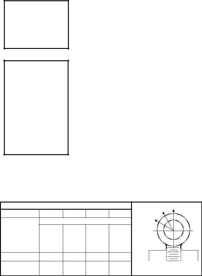
NOTE
The information and tables contained in this article relate to Cincinnati Machine methods and standards. Consult National, Local and Plant Laws and Regulations regarding lifting practices.
WARNING
Before inserting an eyebolt, check to be certain that both the eyebolt and the hole have the same size and type threads. For example: M12 with M12 or
.375-16 with .375-16.
To attend safe working loads, at least 90% of the threaded portion of a standard forged eyebolt must be engaged.
Failure to follow this instruction may result in serious injury.
LIFTING DEVICES
GENERAL
The use of lifting devices is subject to certain hazards that cannot be met by mechanical means but only by the exercise of intelligence, care, and common sense. It is, therefore, essential to have competent and careful operators, physically and mentally fit, thoroughly trained to the safe operation of the equipment and the handling of the loads. Serious hazards are overloading, dropping or slipping of the load caused by improper hitching or slinging, standing or crawling under a load, swinging loads, obstruction to the free passage of the load, using equipment for a purpose or a manner for which it was not intended or designed..
EYEBOLTS
A straight lift is preferred when using eyebolts. An angular lift places additional stresses on an eyebolt, above that of the load to be hoisted.
If the situation necessitates an angular lift, the safe working load for angular lifts shown in Fig. 1 and Fig. 2 should be used.
When multiple eyebolt provisions are designed into a lift, it is recommended (in most applications) that a spreader bar be used. (See Fig. 9 which illustrates a typical spreader bar arrangement.)
No greater stress should be allowed than that given under Safe Working Load in Fig. 1 and Fig. 2.
To obtain greatest strength from an eyebolt, it must fit reasonably tight in the hole with at least 90% of the threaded length engaged.
Eyebolts should never be welded or subjected to heat in excess of 900 F [480 C].
Eyebolts should never be painted or otherwise coated when used for lifting, as such coating will very likely cover up flaws.
Eyebolts should be routinely inspected for defects and if any defects are found, they should be destroyed by melting, crushing, or cutting clear across the eye.
STRAIGHT SHANK INCH (ANSI/ASME B18.15) |
|
90 |
|||
THREAD |
.37516 |
.50013 |
.625-11 |
1.000-8 |
60 |
|
|||||
SAFE WORKING |
|
LBS. [KG] |
|
|
30 |
|
|
|
|
||
LOAD |
|
|
|
|
|
90 DEGREES |
1000 |
1840 |
2940 |
7880 |
|
|
[453] |
[834] |
[1333] |
[3573] |
|
60 DEGREES |
375 |
805 |
1340 |
3670 |
|
|
[170] |
[365] |
[607] |
[1664] |
|
30 DEGREES |
200 |
470 |
805 |
2390 |
|
|
[90] |
[213] |
[365] |
[1083] |
|
PART NUMBER |
3449 |
870 |
21312 |
19489 |
|
IDENTIFICATION |
|
|
|
|
STRAIGHT SHANK INCH |
PLATE NUMBER |
3338325 |
3338326 |
3338327 |
3338328 |
|
Fig. 1
Preferred Inch Lifting Eyebolts
Page 1--6
Cincinnati Machine 91203809--001
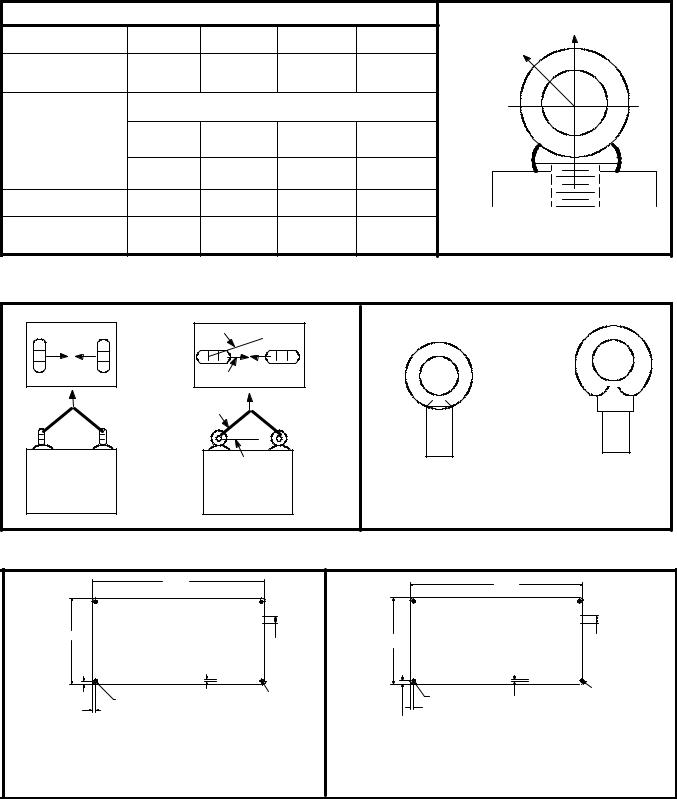
|
SHOULDER METRIC (ISO 3266-1984) |
|
90 |
||
|
|
|
|
|
|
THREAD |
M12 |
M16 |
M20 |
M30 |
45 |
|
|
|
|
|
|
SPOT DIAMETER |
32 mm |
37 mm |
42 mm |
67 mm |
|
|
1.25 in. |
1.50 in. |
1.65 in. |
2.63 in. |
|
SAFE WORKING |
|
[KILOGRAMS] LBS. |
|
|
|
LOAD |
|
|
|
|
|
90 DEGREES |
[400] |
[630] |
[1000] |
[2500] |
|
|
882 |
1389 |
2205 |
5512 |
|
45 DEGREES |
[100] |
[160] |
[250] |
[625] |
|
|
220 |
352 |
551 |
1378 |
|
PART NUMBER |
6014453-3 |
6014453-4 |
6014453-5 |
6014453-8 |
|
IDENTIFICATION |
3338329 |
3338330 |
3338331 |
3338332 |
SHOULDER METRIC |
PLATE NUMBER |
|
||||
Fig. 2
Preferred Metric Lifting Eyebolts
|
5 MAX. |
|
|
NO |
YES |
|
|
LOAD |
LOAD |
|
|
|
30 MIN. |
|
3338329 |
|
|
3338325 |
|
|
|
|
|
NO |
YES |
INCH |
ISO METRIC |
|
.375-16 UNC |
M12 |
|
|
|
||
Fig. 3 |
|
Fig. 4 |
|
Eyebolt Loading |
|
Eyebolt I.D. Plates - Inch and Metric |
|
6.00
THIS MACHINE HAS BEEN
MANUFACTURED TO UTILIZE
”INCH” THREAD LIFTING
3.00 DEVICES. ANY EXCEPTION .25 TO THIS WILL BE LABELED
ADJACENT TO THE LIFT
|
POINT. |
|
3375984 |
|
|
|
|
.12 |
.109 DIA.THRU |
.08 |
.12 R |
.12 |
4 PLACES |
|
|
TYP.
NO 21 (.032) GAGE ALUMINUM.-- NO. AL 5052 ALLOY. ETCHED AREAS TO BE BLACK BAKED ENAMEL. ETCHED DEPTH TO BE .003 TO .005 INCHES
------ OR ------ NO. 21 (.032) GAGE
ALUMINUM WITH METALPHOTO PROCESS. ALL LETTERING TO BE HELVETICA MEDIUM.
150
|
THIS MACHINE HAS BEEN |
|
|
|
|
MANUFACTURED TO UTILIZE |
|
|
|
|
”METRIC” THREAD LIFTING |
|
6.3 |
|
75 |
DEVICES. ANY EXCEPTION |
|
||
|
TO THIS WILL BE LABELED |
|
|
|
|
ADJACENT TO THE LIFT |
|
|
|
|
POINT. |
|
3375983 |
|
|
|
|
|
|
|
1.4 |
2 |
|
3 R |
|
THRU--4 |
|
|
|
|
|
|
|
|
3 TYP. |
3 TYP. |
|
|
|
PLACES |
|
|
|
|
NO 21 (.032) GAGE ALUMINUM.-- NO. AL 5052 ALLOY. ETCHED AREAS TO BE BLACK |
||||
BAKED ENAMEL. ETCHED DEPTH TO BE .003 to .005 INCHES |
------ OR ------ NO. 21 (.032) |
|||
GAGE ALUMINUM |
|
|
|
|
WITH METALPHOTO PROCESS. ALL LETTERING TO BE HELVETICA MEDIUM.
SURFACE GRAIN TO RUN PARALLEL TO LETTERING WITH SATIN FINISH.
Fig. 5 |
Fig. 6 |
Instruction Plate - Inch (Part Number 3375984) |
Instruction Plate - Metric (Part Number 3375983) |
Cincinnati Machine 91203809--001 |
Page 1--7 |

Fig. 7
Hoist Ring
HOIST RINGS
Hoist Rings are superior to eyebolts for angular lifting.
Be certain the thread projection is in accordance with the manufacturer’s recommendation.
Do not recut any damaged threads on hoist rings.
To obtain the safe working load, torque to the recommended values shown in the table below.
Observe all other safety precautions normally practiced on eyebolts.
|
|
|
|
|
F |
F |
|
|
|
|
|
|
|
|
|
|
|
|
|
|
|
|
F |
F |
F |
|
F |
F |
F |
.xxx-xx |
|
|
|
|
THREAD |
|
|
60 |
|
45 |
|
|
30 |
|
|||
CM HOIST |
THREAD |
90 |
|
|
|
|
|
|
|
||||||
TORQUE |
_ |
|
_ |
|
_ |
|
|
_ |
|
|
|
||||
RING |
|
SIZE |
|
|
|
|
|
|
|
||||||
|
|
|
W W |
W W |
W W |
|
W W |
|
|
||||||
PART NO. |
|
|
|
MAX. WT |
MAX. WT |
MAX. WT |
|
MAX. WT |
CM IDENT. |
||||||
|
|
|
|
|
|
||||||||||
|
|
|
|
|
EACH RING |
EACH RING |
EACH RING |
|
EACH RING |
PLATE |
|
||||
|
|
|
|
|
|
|
|
|
|
|
|
|
|
PART. NO. |
|
|
|
|
Ft-Lb N-m |
Lb |
kg |
Lb |
kg |
Lb |
kg |
|
Lb |
kg |
|
|
|
3346225 |
1 |
.375-16 |
12.0 |
16.3 |
1000 |
450 |
866 |
390 |
707 |
318 |
|
500 |
225 |
5013055 |
001 |
3346225 |
2 |
.500-13 |
28.0 |
38 |
2500 |
1130 |
2165 |
975 |
1767 |
795 |
|
1250 |
562 |
5013055 |
002 |
3346225 |
3 |
.625-11 |
60.0 |
81.3 |
4000 |
1810 |
3464 |
1559 |
2828 |
1273 |
|
2000 |
900 |
5013055 |
003 |
3346225 |
4 |
1.000-8 |
230.0 |
312 |
10000 |
4500 |
8660 |
3897 |
7071 |
3182 |
|
5000 |
2250 |
5013055 |
004 |
3346225 |
6 |
M12X1.75 |
27.0 |
36.6 |
2204 |
991 |
1908 |
859 |
1558 |
701 |
|
1102 |
496 |
5013055 |
006 |
3346225 |
7 |
M16X2 |
59.0 |
80 |
3857 |
1736 |
3340 |
1503 |
2726 |
1227 |
|
1928 |
868 |
5013055 |
007 |
3346225 |
8 |
M20X2.5 |
100.0 |
136 |
4736 |
2132 |
4103 |
1846 |
3349 |
1507 |
|
2369 |
1066 |
5013055 |
008 |
3346225 |
9 |
M30X3.5 |
229.0 |
310 |
9257 |
4166 |
8016 |
3607 |
6544 |
2945 |
|
4628 |
2083 |
5013055 |
009 |
|
|
|
|
|
F |
F |
F |
F |
F |
|
F |
|
|
|
|
|
|
|
|
|
|
|
90 |
|
90 |
|
|
|
|
|
|
|
|
|
|
|
90 |
|
|
|
|
|
|
|
|
|
|
CM HOIST |
THREAD |
THREAD |
|
|
|
|
|
|
|
|
|
|
|||
_ |
|
|
|
W W |
|
|
|
.xxx-xx |
|||||||
TORQUE |
|
W W |
|
|
|
||||||||||
RING |
|
SIZE |
|
|
|
|
|||||||||
|
W W |
|
|
|
|
|
|||||||||
PART NO. |
|
|
|
MAX. WT |
MAX. WT |
MAX. WT |
|
|
|
|
|
||||
|
|
|
|
|
|
|
|
|
|
||||||
|
|
|
|
|
EACH RING |
EACH RING |
EACH RING |
|
|
|
CM IDENT. |
||||
|
|
|
Ft-Lb N-m |
Lb |
kg |
Lb |
kg |
Lb |
kg |
|
Ft-Lb |
N-m |
PLATE |
|
|
|
|
|
|
PART. NO. |
|||||||||||
3346225 |
1 |
.375-16 |
12.0 |
16.3 |
1000 |
450 |
1000 |
450 |
1000 |
450 |
|
|
|
5013055 |
001 |
3346225 |
2 |
.500-13 |
28.0 |
38 |
2500 |
1130 |
2500 |
1130 |
2500 |
1130 |
|
|
|
5013055 |
002 |
3346225 |
3 |
.625-11 |
60.0 |
81.3 |
4000 |
1810 |
4000 |
1810 |
4000 |
1810 |
|
|
|
5013055 |
003 |
3346225 |
4 |
1.000-8 |
230.0 |
312 |
10000 |
4500 |
10000 |
4500 |
10000 |
4500 |
|
|
|
5013055 |
004 |
3346225 |
6 |
M12X1.75 |
27.0 |
36 |
2204 |
991 |
2204 |
991 |
2204 |
991 |
|
|
|
5013055 |
006 |
3346225 |
7 |
M16X2 |
59.0 |
80 |
3857 |
1736 |
3857 |
1736 |
3857 |
1736 |
|
|
|
5013055 |
007 |
3346225 |
8 |
M20X2.5 |
100.0 |
136 |
4736 |
2132 |
4736 |
2132 |
4736 |
2132 |
|
|
|
5013055 |
008 |
3346225 |
9 |
M30X3.5 |
229.0 |
310 |
9257 |
4166 |
9257 |
4166 |
9257 |
4166 |
|
|
|
5013055 |
009 |
Fig. 8 |
|
|
|
|
|
|
|
|
|
NOTE F=FORCE W=WEIGHT |
|
||||
Hoist Ring Table |
|
|
|
|
|
|
|
|
|
||||||
Page 1--8
Cincinnati Machine 91203809--001
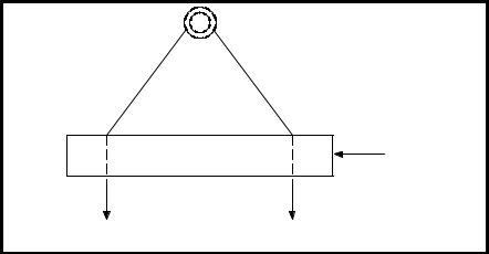
SPREADER BARS AND LIFTING BEAMS
SPREADER
TO LOAD |
TO LOAD |
Fig. 9
Spreader Bar - Typical
Spreader bars are used when multiple eyebolts are designed into a lift. Always observe the following safety precautions when using a spreader bar or lifting beam
Do not exceed the safe working load.
Use the spreader or beam to handle parts or components only for which it was designed.
Inspect it before each use.
Do not alter or weld anything to bar or beam.
Store properly to avoid damage.
CHAIN
Select a chain with the suitable characteristics and capacity for the load. See above. Always observe the following safety precautions.
Do not shorten chains with knots, bolts, or any non-approved method.
Never use damaged chain.
Hitch chain securely to the load.
Pad sharp corners with material of sufficient strength to withstand load and protect chain.
Cincinnati Machine 91203809--001 |
Page 1--9 |

|
|
|
DOUBLE SLING CHAINS |
TRIPLE SLING CHAINS |
QUAD SLING CHAINS |
||||||||||
|
|
SINGLE |
|
TYPE D |
|
|
TYPE T |
|
|
|
TYPE Q |
|
|||
SIZE OF |
|
|
|
|
|
|
|
|
|
|
|
|
|
|
|
|
CHAIN |
60 |
45 |
30 |
|
60 |
|
45 |
|
30 |
60 |
45 |
30 |
||
CHAIN |
|
|
|
|
|||||||||||
|
90 |
|
|
|
|||||||||||
|
|
|
|
|
|
|
|
|
|
|
|
|
|
|
|
|
|
|
|
|
|
|
|
|
|
|
|
|
|
|
|
|
|
|
|
|
|
|
|
|
|
|
|
|
|||
9/32 in. |
lbs. |
3 250 |
5 625 |
4 600 |
3 250 |
8 400 |
6 900 |
4 875 |
8400 |
|
6900 |
4 875 |
|||
|
|
|
|
|
|
|
|
|
|
|
|
|
|||
.7.2 mm |
kg. |
1 475 |
2 550 |
2 085 |
1 475 |
3 810 |
3 130 |
2 210 |
3 810 |
|
3 130 |
2 210 |
|||
|
|
|
|
|
|
|
|
|
|
|
|
|
|||
3/8 in. |
lbs. |
6 600 |
11 400 |
9 300 |
6 600 |
17 100 |
13 950 |
9 900 |
17 100 |
|
13 950 |
9 900 |
|||
|
|
|
|
|
|
|
|
|
|
|
|
|
|||
9.5 mm |
kg. |
2 995 |
5 170 |
4 220 |
2 995 |
7 750 |
6 330 |
4 490 |
7750 |
|
6 330 |
4 490 |
|||
|
|
|
|
|
|
|
|
|
|
|
|
|
|||
1/2 in. |
lbs. |
11 250 |
19 700 |
15 900 |
11 250 |
29 250 |
23 850 |
16 875 |
29 250 |
|
23 850 |
16 875 |
|||
|
|
|
|
|
|
|
|
|
|
|
|
|
|||
712.7 mm |
kg. |
5 100 |
8 845 |
7 210 |
5 100 |
13 270 |
10 820 |
7650 |
13 270 |
|
10 820 |
7650 |
|||
|
|
|
|
|
|
|
|
|
|
|
|
|
|||
5/8 in. |
lbs. |
16 500 |
28 600 |
23 300 |
16 500 |
42 900 |
34 950 |
24 750 |
42 900 |
|
34 950 |
24 750 |
|||
|
|
|
|
|
|
|
|
|
|
|
|
|
|||
15.9 mm |
kg. |
7 480 |
12 970 |
10 570 |
7 480 |
19 460 |
15 850 |
11 230 |
19 460 |
|
15 850 |
11 230 |
|||
|
|
|
|
|
|
|
|
|
|
|
|
|
|||
3/4 in. |
lbs. |
23 000 |
39 800 |
32 500 |
23 000 |
59 700 |
48 750 |
34 500 |
59 700 |
|
48 700 |
34 500 |
|||
|
|
|
|
|
|
|
|
|
|
|
|
|
|||
19.1 mm |
kg. |
10 430 |
18 050 |
14 740 |
10 430 |
27 080 |
22 110 |
15 650 |
27 080 |
|
22 110 |
15 650 |
|||
|
|
|
|
|
|
|
|
|
|
|
|
|
|||
7/8 in. |
lbs. |
28 750 |
49 800 |
40 700 |
28 750 |
74 700 |
61 050 |
43 125 |
74 700 |
|
61 050 |
43 125 |
|||
|
|
|
|
|
|
|
|
|
|
|
|
|
|||
22.6 mm |
kg. |
13 040 |
22 590 |
18 460 |
13 040 |
33 880 |
27 690 |
19 560 |
33 880 |
|
27 690 |
19 560 |
|||
|
|
|
|
|
|
|
|
|
|
|
|
|
|||
1 in. |
lbs. |
38 750 |
67 100 |
54 800 |
38 750 |
100 650 |
82 200 |
58 125 |
100 660 |
|
82 200 |
58 125 |
|||
|
|
|
|
|
|
|
|
|
|
|
|
|
|||
25.4 mm |
kg. |
17 580 |
30 440 |
24 860 |
17 580 |
45 650 |
37 290 |
26 260 |
45 650 |
|
37 290 |
26 260 |
|||
|
|
|
|
|
|
|
|
|
|
|
|
|
|||
1 1/4 in. |
lbs. |
57 500 |
99 600 |
81 300 |
57 500 |
149 400 |
121 950 |
86 250 |
149 400 |
|
121 950 |
86 250 |
|||
|
|
|
|
|
|
|
|
|
|
|
|
|
|||
31.8 mm |
kg. |
26 080 |
45 180 |
36 880 |
26 080 |
67 770 |
55 320 |
39 120 |
67 770 |
|
55 320 |
39 120 |
|||
|
|
|
|
|
|
|
|
|
|
|
|
|
|
|
|
1 1/2 in. |
lbs. |
80 000 |
138 500 |
113 000 |
80 000 |
|
|
|
|
|
|
|
|
|
|
|
|
|
|
|
|
|
|
|
|
|
|
|
|
|
|
38.1 mm |
kg. |
36 290 |
62 820 |
51 260 |
36 290 |
|
|
|
|
|
|
|
|
|
|
|
|
|
|
|
|
|
|
|
|
|
|
|
|
|
|
1 3/4 in. |
lbs. |
100 000 |
73 200 |
41 000 |
100 000 |
|
|
|
|
|
|
|
|
|
|
|
|
|
|
|
|
|
|
|
|
|
|
|
|
|
|
44.5 mm |
kg. |
45 360 |
78 560 |
63 960 |
45 360 |
|
|
|
|
|
|
|
|
|
|
|
|
|
|
|
|
|
|
|
|
|
|
|
|
|
|
2 in. |
lbs. |
130 000 |
225 000 |
183 000 |
130 000 |
|
|
|
|
|
|
|
|
|
|
|
|
|
|
|
|
|
|
|
|
|
|
|
|
|
|
50.8 mm |
kg. |
26 750 |
102 060 |
83 000 |
26 750 |
|
|
|
|
|
|
|
|
|
|
|
|
|
|
|
|
|
|
|
|
|
|
|
|
|
|
Fig. 10
Steel Alloy Chains
Keep hands and fingers from between the chain and load.
Avoid shock loading - particularly when working at temperatures below 40
F [4 C].
Never pull chain from under load when load is resting on chain.
Correct kinks and twisting in chain before lifting.
Lift from center of hooks. Avoid lifting from the point.
Assure that load is free to move before lifting. Keep clear of all obstructions.
When using a basket hitch, balance load and assure that chain legs contain or support load from the sides above the center of gravity.
Store chains in an area where they will not be subject to mechanical damage or corrosive action.
Page 1--10
Cincinnati Machine 91203809--001
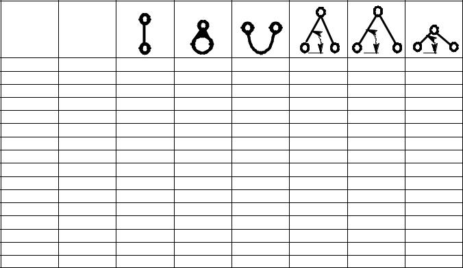
CABLE SLINGS
Select the appropriate size wire rope and hitch. See Table below
CABLE |
ESTIMATED |
VERTICAL |
CHOKER |
BASKET |
60 |
45 |
30 |
SIZE |
RATING CA- |
|
HITCH |
HITCH |
|||
|
|
|
|
||||
|
PACITY |
|
|
|
|
|
|
|
(For Exact |
|
|
|
|
|
|
|
Rating Check |
|
|
|
|
|
|
|
Sling Tag) |
|
|
|
|
|
|
1/4 in. |
lbs. |
980 |
740 |
1400 |
1700 |
1400 |
980 |
6.4 mm |
kg. |
445 |
335 |
635 |
770 |
635 |
445 |
1/2 in. |
lbs. |
3600 |
2800 |
5200 |
6400 |
5200 |
3600 |
712.7 mm |
kg. |
1630 |
1270 |
2360 |
2900 |
2360 |
1630 |
3/4 in. |
lbs. |
7800 |
5800 |
11100 |
13600 |
11100 |
7800 |
19.1 mm |
kg. |
3450 |
2630 |
5035 |
6170 |
5035 |
3450 |
1 in. |
lbs. |
13400 |
1000 |
18800 |
22000 |
18800 |
13400 |
25.4 mm |
kg. |
6080 |
4540 |
8530 |
9980 |
8530 |
6080 |
1 1/4 in. |
lbs. |
19600 |
14800 |
28000 |
34000 |
28000 |
19600 |
31.8 mm |
kg. |
8890 |
6710 |
12700 |
15420 |
12700 |
6710 |
1 1/2 in. |
lbs. |
28000 |
20000 |
40000 |
48000 |
40000 |
28000 |
38.1 mm |
kg. |
12700 |
9070 |
18140 |
21770 |
18140 |
12700 |
1 3/4 in. |
lbs. |
38000 |
28000 |
54000 |
66000 |
54000 |
38000 |
44.5 mm |
kg. |
17240 |
12700 |
24490 |
29940 |
24490 |
17240 |
2 in. |
lbs. |
50000 |
36000 |
70000 |
86000 |
70000 |
50000 |
50.8 mm |
kg. |
22680 |
16330 |
31750 |
39000 |
31750 |
22680 |
Fig. 11
Wire Rope Slings
Guide loads with a tag line when practical.
When using multiple leg sling, select longest one possible.
Examine for damaged or worn area.
Attach securely to load.
Pad sharp corners to protect wire rope.
Center load in the base (bowl) of the hook to prevent hook point loading.
Do not kink, twist, or loop legs.
Keep hands and fingers from between wire rope and load.
Stand clear of attached load.
Start lift slowly to avoid shock injury.
Do not pull wire rope from under a load when the load is resting on it.
Do not shorten sling by knotting, by wire rope clips, or by any other means.
Do not inspect wire rope by passing bare hands over the body. Broken wire, if present, may puncture the hands.
Keep wire rope well-lubricated to prevent corrosion.
Use gloves at all times when handling.
Cincinnati Machine 91203809--001 |
Page 1--11 |

SYNTHETIC MATERIAL SLINGS
Select the sling with the suitable characteristics and capability for the load and environment. See Fig. 12
AS THE SLING TO LOAD ANGLE |
USE THIS CHART |
RATED SLING CAPACITY-ONE LEG |
||||||||||||
DECREASES, SO DOES THE RATED CA- |
|
|
|
|||||||||||
PACITY OF A SLING. |
FOR ALL TYPE |
SLING |
If Sling Ca- |
Then Actual |
||||||||||
|
|
|
|
|
|
|
|
SLINGS; ROPE, |
||||||
SLING--TO--LOAD ANGLE IS ALWAYS |
pacity |
Sling Capacity |
||||||||||||
CHAIN, OR NYLON. |
LIFTING |
|||||||||||||
|
is ... |
|||||||||||||
THE ANGLE BETWEEN THE SLING LEG AND |
|
|
|
EFFICIENCY |
at 90 is... |
(LB. [KG]) |
||||||||
|
|
|
(LB. [KG]) |
|||||||||||
THE HORIZONTAL SURFACE. |
|
|
|
|||||||||||
|
|
|
|
|
|
|||||||||
|
|
|
|
|
|
|
|
|
|
|
|
|
|
|
90 |
|
100.0 % |
1000 |
1000 |
||||||||||
|
|
|
|
[454 ] |
[454 ] |
|||||||||
|
|
|
|
|
|
|
|
|
|
|
|
|||
|
|
|
|
|
|
|
|
|
|
|
|
|
|
|
|
|
|
|
|
|
|
|
75 |
96.6 % |
1000 |
968 |
|||
|
|
|
|
|
|
|
|
|
|
|
[454 ] |
[439 ] |
||
|
|
|
|
|
|
|
|
|
|
|
|
|||
|
|
|
|
|
|
|
|
|
|
|
|
|
|
|
|
|
|
|
|
|
|
|
|
60 |
86.6 % |
1000 |
866 |
||
|
|
|
|
|
|
|
|
|
|
|
|
[454 ] |
[390 ] |
|
|
|
SLING |
|
|
45 |
70.7 % |
1000 |
707 |
||||||
|
|
ANGLE |
|
|
||||||||||
|
|
TO LOAD |
|
|
|
|
|
|
|
|||||
|
|
|
|
|
|
|
|
|
|
|
|
[454 ] |
[320 ] |
|
|
|
|
|
|
|
|
|
|
|
|
|
|||
|
|
|
|
|
|
|
|
|
|
|
|
|
|
|
|
|
|
|
|
|
|
|
|
|
50.0 % |
1000 |
500 |
||
|
|
|
|
|
|
|
|
|
||||||
|
|
|
|
|
|
|
|
30 |
|
|
[454 ] |
[225 ] |
||
|
|
|
|
|
|
|
|
|
|
|
|
|||
|
|
|
|
|
|
|
|
|
|
|
|
|
|
|
|
|
|
|
|
|
|
|
|
|
|
|
|
|
|
|
|
|
|
|
|
|
|
|
|
|
|
|
|
|
Fig. 12
Sling Load Angle Chart
When using a choker hitch, the sling shall be long enough to assure that the choking action is on the webbing.
Slings used in a basket hitch shall have the load balanced.
Do not drag slings over the floor or any abrasive surface.
Do not twist or tie knots in slings.
Never pull sling from load when the load is resting on it.
Protect sling from sharp corners and abrasive surfaces.
Do not drop slings.
Store slings in an area where they will not be subject to mechanical or chemical damage.
Do not use where acid conditions exist.
Do not use polyester and polypropylene slings where caustic conditions exist.
Do not use polyester and nylon slings at temperatures in excess of 180
F nor polypropylene slings at temperatures in excess of 200 F.
Do not use aluminum fittings where caustic conditions exist.
Page 1--12
Cincinnati Machine 91203809--001

P TYPE HOOKS
P type hooks are a proprietary design and should be considered for heavy (machine and unit) lifts.
Fig. 14 gives dimensional data, safe working loads and screw torque values for P type hooks.
The use of these hooks must be shown on the assembly drawing, listed in the Bill of Material and shown in the lifting section of the Service Manual.
B |
D |
C |
F |
E |
A |
Fig. 13
“P” Type Lifting Hooks
PART |
LIFTING |
|
|
|
|
|
|
|
|
SCREW |
SCREW |
|
CAPACITY |
A |
B |
C |
D |
E |
F |
SCREW NO. |
QTY. |
TORQUE |
TORQUE |
||
NO. |
||||||||||||
LBS. [KG] |
INCH |
INCH |
INCH |
INCH |
INCH |
INCH |
|
|
LB./FT. |
N-m |
||
|
|
|
||||||||||
|
|
|
|
|
|
|
|
|
|
|
|
|
402517 |
1800 [818] |
2.00 |
9.75 |
4.50 |
3.00 |
2.50 |
--- |
2415 |
2 |
160 |
217 |
|
|
|
|
|
|
|
|
|
|
|
|
|
|
296513 |
2500 [1136] |
1.75 |
10.63 |
4.00 |
2.50 |
4.00 |
--- |
2415 |
2 |
160 |
217 |
|
|
|
|
|
|
|
|
|
|
|
|
|
|
296514 |
3500 [1590] |
2.00 |
12.25 |
4.50 |
3.00 |
2.50 |
5.00 |
2415 |
3 |
160 |
217 |
|
|
|
|
|
|
|
|
|
|
|
|
|
|
402335 |
5000 [2273] |
2.25 |
12.25 |
4.50 |
3.00 |
5.00 |
--- |
180139 |
2 |
370 |
502 |
|
|
|
|
|
|
|
|
|
|
|
|
|
|
296515 |
8000 [3636] |
2.25 |
15.75 |
4.50 |
3.00 |
4.00 |
7.88 |
180139 |
3 |
370 |
502 |
|
|
|
|
|
|
|
|
|
|
|
|
|
WHEN DESIGNING METRIC SIZES SEE THE CURRENT LIFTING MANUAL
Fig. 14
“P” Type Lifting Hooks
S HOOKS
The use of S hooks in conjunction with some of the other lifting devices dictates additional safety rules which must always be practiced.
Never use more than one S hook in a single chain link or hook.
Inspect the S hook before each use and if damaged destroy by cutting into two pieces.
Never exceed the safe working load which should be stamped on each hook.
Do not paint, weld, or expose an S hook to high heat.
Cincinnati Machine 91203809--001 |
Page 1--13 |

Do not use when either or both S hooks are opened more than 15% of the normal throat opening or twisted more than 10 from the plane of the unbent hook.
B
STAMP TO
INDICATE ALLOY
A
C
R (REF.)
C
STAMP WORKING LOAD LIMIT WITH LOW STRESS CHARACTERS PER NUCLEAR AMERICAN SOCIETY OF MECHANICAL ENGINEERS CODE
SECTION III, DIV. 1, PARAGRAPH NA--3766.6 (2)
STAMP MFGR. NAME OR TRADEMARK FOR IDENTIFICATION
Fig. 15
“S” Hooks
|
MAX. WORKING |
|
|
ALL DIMENSIONS IN |
|
S-HOOK |
||||
|
LOAD |
|
|
|
INCHES |
|
WEIGHT |
|||
|
MANUFACTURER AND |
|
|
(See Fig 16.) |
|
|||||
|
|
|
|
|
|
|
||||
|
|
|
|
|
|
|
|
|
|
|
|
|
|
|
|
|
|
|
|
|
|
PART NO. |
LBS. |
KG |
CODE NUMBER |
A |
|
B |
C |
|
R |
LBS. |
|
|
|
|
|
|
|
|
|
|
|
3590535--5 |
650 |
294 |
CM Chain 562250 |
0.500 |
|
7.50 |
2.00 |
|
1.00 |
0.80 |
|
|
|
|
|
|
|
|
|
|
|
|
|
|
Amer. Chain & Cable 5933--00800 |
0.500 |
|
5.50 |
1.50 |
|
0.75 |
0.63 |
|
|
|
|
|
|
|
|
|
|
|
3590535--7 |
1 015 |
460 |
CM Chain 562262 |
0.625 |
|
9.00 |
2.50 |
|
1.25 |
1.60 |
|
|
|
|
|
|
|
|
|
|
|
|
|
|
Amer. Chain & Cable 5933--01000 |
0.625 |
|
7.00 |
1.88 |
|
0.94 |
1.30 |
|
|
|
|
|
|
|
|
|
|
|
3590535--8 |
1 465 |
664 |
CM Chain 562275 |
0.750 |
|
10.50 |
3.00 |
|
1.50 |
2.60 |
|
|
|
|
|
|
|
|
|
|
|
|
|
|
Amer. Chain & Cable 5933--01200 |
0.750 |
|
8.25 |
2.25 |
|
1.12 |
2.10 |
|
|
|
|
|
|
|
|
|
|
|
3590535--9 |
1 990 |
902 |
CM Chain 562287 |
0.875 |
|
12.00 |
3.50 |
|
1.75 |
4.20 |
|
|
|
|
|
|
|
|
|
|
|
|
|
|
Amer. Chain & Cable 5933--01400 |
0.875 |
|
9.62 |
2.62 |
|
1.31 |
3.40 |
|
|
|
|
|
|
|
|
|
|
|
3590535--10 |
2 600 |
1179 |
CM Chain 562300 |
1.000 |
|
13.00 |
4.00 |
|
2.00 |
6.00 |
|
|
|
|
|
|
|
|
|
|
|
|
|
|
Amer. Chain & Cable 5933--01600 |
1.000 |
|
11.00 |
3.00 |
|
1.50 |
5.10 |
|
|
|
|
|
|
|
|
|
|
|
3590535--12 |
3 290 |
1492 |
CM Chain 562310--B |
1.125 |
|
15.00 |
4.50 |
|
2.25 |
8.70 |
|
|
|
|
|
|
|
|
|
|
|
|
|
|
Amer. Chain & Cable 5933--01800 |
1.125 |
|
12.12 |
3.38 |
|
1.69 |
7.00 |
|
|
|
|
|
|
|
|
|
|
|
3590535--14 |
4 065 |
1843 |
CM Chain 562325--B |
1.250 |
|
16.00 |
5.00 |
|
2.50 |
11.70 |
|
|
|
|
|
|
|
|
|
|
|
|
|
|
Amer. Chain & Cable 5933--02000 |
1.250 |
|
13.75 |
3.75 |
|
1.88 |
10.00 |
|
|
|
|
|
|
|
|
|
|
|
3590535--15 |
4 915 |
2229 |
CM Chain 562337--B |
1.375 |
|
17.00 |
5.50 |
|
2.75 |
15.40 |
|
|
|
|
|
|
|
|
|
|
|
|
|
|
Amer. Chain & Cable 5933--02200 |
1.375 |
|
14.88 |
4.12 |
|
2.06 |
13.00 |
|
|
|
|
|
|
|
|
|
|
|
3590535--16 |
5 850 |
2653 |
CM Chain 562350--B |
1.500 |
|
18.00 |
6.00 |
|
3.00 |
19.50 |
|
|
|
|
|
|
|
|
|
|
|
|
|
|
Amer. Chain & Cable 5933--02400 |
1.500 |
|
16.50 |
4.50 |
|
2.25 |
17.50 |
|
|
|
|
|
|
|
|
|
|
|
3590535--18 |
9 500 |
4309 |
Amer. Chain & Cable 5933--02800 |
1.750 |
|
19.25 |
5.25 |
|
2.62 |
28.00 |
|
|
|
|
|
|
|
|
|
|
|
3590535--20 |
12 500 |
5669 |
Amer. Chain & Cable 5933--03200 |
2.000 |
|
22.00 |
6.00 |
|
6.00 |
41.00 |
|
|
|
|
|
|
|
|
|
|
|
3590535--25 |
19 000 |
8618 |
Amer. Chain & Cable 5933--04000 |
2.500 |
|
27.50 |
7.50 |
|
9.75 |
79.00 |
|
|
|
|
|
|
|
|
|
|
|
Fig. 16
“S” Hooks
Page 1--14
Cincinnati Machine 91203809--001
Loading...