

Page 1

Section 7 operation
A SUPPLEMENT TO THE OPERATION MANUAL FOR THE
CINCINNATI CL-900 SERIES
LASER SYSTEM
For CINCINNATI Laser Control Software Version 8.3
CINCINNATI INCORPORATED
CINCINNATIR
EM-551 (N-04/11) COPYRIGHT 2011
C I N C I N N A T I, OHIO 4 5 2 1 1
CINCINNATI INCORPORATED
Page 2

Page 3

Section X : title contentS
Section 7: operation contentS
INTRODUCTION
HMI OVERVIEW
LASER SYSTEM DISPLAY WINDOW ...........................................................7-1
MENU BAR...............................................................................................7-2
TOOL BAR................................................................................................7-2
STATUS INDICATORS CONTROL BAR ..................................................7-3
PROCESS STATUS BAR .........................................................................7-3
APPLICATION WORKSPACE ..................................................................7-3
OPERATOR CONSOLE CONTROL BAR ................................................7-4
PROGRAM STATUS BAR ........................................................................7-4
MAIN STATUS BAR .................................................................................7-4
FILE TYPES ................................................................................................... 7-5
NC PROGRAM FILE ................................................................................7-5
PROCESS PARAMETER FILE ................................................................7-5
BATCH PROGRAM FILE .........................................................................7-6
CNC RUN WINDOW ...................................................................................... 7-7
CONTROL BARS
OPERATOR CONSOLE .................................................................................7-8
PROGRAM MODES .................................................................................7-8
LASER CONTROLS ...............................................................................7-10
OVERRIDE SETTINGS ..........................................................................7-10
OPERATING MODES ............................................................................ 7-11
OVERRIDE ADJUST ...................................................................................7-12
AUXILIARY FUNCTIONS .............................................................................7-13
MENU COMMANDS
FILE MENU ..................................................................................................7-14
NEW .......................................................................................................7-14
OPEN .....................................................................................................7-14
QUICK FILE OPEN ................................................................................7-16
OPEN LOADED PROGRAM ..................................................................7-16
OPEN CURRENT PROCESS ................................................................7-16
CLOSE ...................................................................................................7-17
SAVE ......................................................................................................7-17
SAVE AS .................................................................................................7-17
LOAD NC PROGRAM ............................................................................7-18
LOAD CURRENT PROGRAM ................................................................7-18
LOAD CURRENT BATCH ......................................................................7-19
PLOT NC PROGRAMS ..........................................................................7-19
RESTART LOADED PROGRAM ............................................................7-20
PRINT .....................................................................................................7-21
PRINT PREVIEW ...................................................................................7-22
PRINT SETUP ........................................................................................7-22
MRU FILE LIST ......................................................................................7-23
OPEN OPERATOR LOG ........................................................................7-23
EXIT ........................................................................................................7-23
EDIT MENU ..................................................................................................7-23
UNDO… .................................................................................................7-24
CUT ........................................................................................................7-24
COPY .....................................................................................................7-24
PASTE ....................................................................................................7-24
FIND .......................................................................................................7-24
REPLACE ...............................................................................................7-25
VIEW MENU .................................................................................................7-25
CONTROL BAR ......................................................................................7-25
LANGUAGE............................................................................................7-26
UNITS .....................................................................................................7-27
ALARMS AND MESSAGES WINDOW ..................................................7-27
EM-551 (N-04/11)
Page 4

AXES POSITIONS .................................................................................7-28
MODAL G CODES .................................................................................7-29
ALL POSITION INFORMATION .............................................................7-29
RUN WINDOW GRAPHICS ...................................................................7-30
WINDOW ZOOMING ..............................................................................7-30
MAINTENANCE MENU ................................................................................7-31
CONFIGURATION ..................................................................................7-31
DIAGNOSTICS .......................................................................................7-40
PALLET GATE CONTROL .....................................................................7-43
STATISTICS ...........................................................................................7-44
LASER MENU .............................................................................................. 7-45
LASER STATUS MONITOR ...................................................................7-45
AUTO SHUT-DOWN ..............................................................................7-46
LASER DIAGNOSTICS ..........................................................................7-47
VARIABLES MENU ......................................................................................7-48
LOCAL/GLOBAL VARIABLES ................................................................7-48
USER I/O VARIABLES ...........................................................................7-48
WORK OFFSETS ...................................................................................7-49
MACHINE OFFSETS .............................................................................7-49
UTILITIES MENU ......................................................................................... 7-49
STANDOFF CALIBRATION ....................................................................7-50
OPERATOR SETUP ...............................................................................7-50
LENS CENTERING ................................................................................7-53
SPEED GAS ...........................................................................................7-55
WINDOW MENU .......................................................................................... 7-55
CASCADE ..............................................................................................7-55
TILE ........................................................................................................7-55
ARRANGE ICONS .................................................................................7-55
WINDOW 1, 2 ... .....................................................................................7-55
HELP MENU .................................................................................................7-56
TOPICS ..................................................................................................7-56
MANUALS ..............................................................................................7-56
ABOUT CINCINNATI LASER SYSTEM .................................................7-56
CUTTING PROCESS PARAMETERS
INTRODUCTION ..........................................................................................7-57
PROCESS PARAMETER WINDOW ............................................................7-58
PIERCE PARAMETERS .........................................................................7-58
RAMPED PIERCE PARAMETERS ........................................................7-59
RAPID PIERCE PARAMETERS .............................................................7-60
CUT PARAMETERS ...............................................................................7-61
FOCUS PARAMETERS .........................................................................7-64
PROCESS PARAMETER NOTES .........................................................7-65
START-UP AND SHUT-DOWN
LASER SYSTEM START-UP ........................................................................7-65
CHILLER WARM-UP ....................................................................................7-67
SHUTTING DOWN THE LASER SYSTEM ..................................................7-68
CALIBRATION AND ADJUSTMENT PROCEDURES
NOZZLE STANDOFF CALIBRATION ...........................................................7-69
NONCONTACT STANDOFF SENSING ................................................ 7-69
LASER SHOT ...............................................................................................7-70
SETUP FOR A LASER SHOT ................................................................7-70
TAKING A LASER SHOT ........................................................................7-71
CENTERING THE FOCUSING LENS ..........................................................7-71
LENS CENTERING PROCEDURE ........................................................7-72
LENS FOCAL POINT LOCATION ................................................................7-75
FOCUS CALIBRATION - AUTO FOCUS HEAD ....................................7-76
ASSIST GAS PRESSURE ADJUSTMENT................................................... 7-77
RAPID PIERCE ADJUSTMENTS .................................................................7-77
EM-551 (N-04/11)
CUTTING PROCEDURES
FIRST RUN OF PARTS ................................................................................7-78
ERROR RECOVERY....................................................................................7-80
CUTTING HEAD BREAKAWAY .............................................................7-80
Page 5

RESTARTING A PROGRAM ..................................................................7-80
BATCH MODE PROGRAM EXECUTION ....................................................7-81
MACHINE SETUP CHECKING ....................................................................7-82
AUTO FOCUS CUTTING HEAD
FOCUS CONTROL SYSTEM CONFIGURATION ........................................7-84
AUTO FOCUS SETUP .................................................................................7-85
FOCUS CONTROL SYSTEM HOME OFFSETS ................................... 7-85
FOCUS SETUP FOR LENS CENTERING ............................................7-86
FOCUS-RELATED PROCESS PARAMETERS ...........................................7-87
AUTO FOCUS OPERATION ........................................................................7-87
HOMING THE FOCUS CONTROL SYSTEM .........................................7-87
WINDOWS ADMINISTRATION
MANAGER ACCOUNT .................................................................................7-89
LASER UTILITIES FOLDER ..................................................................7-89
SOFTWARE INSTALLATION AND UPGRADES ....................................7-90
SETUP ACCOUNT .......................................................................................7-90
SOFTWARE INSTALLATION AND UPGRADES ....................................7-91
EMERGENCY REPAIR DISK .................................................................7-91
NETWORK SETUP ................................................................................7-91
JOINING A DOMAIN...............................................................................7-91
DRIVE DESIGNATIONS ...............................................................................7-92
MAPPING NETWORK DRIVES .............................................................7-92
BACKING UP THE CONTROL .....................................................................7-92
MULTIPLE OPERATOR USER ACCOUNTS ............................................... 7-92
TOUCHSCREEN CALIBRATION .................................................................7-92
ALARMS AND MESSAGES
OPERATOR FYI MESSAGES ...................................................................... 7-93
SYSTEM ALARMS .......................................................................................7-95
PROGRAM ERRORS .................................................................................7-101
LASER ALARMS ........................................................................................7-104
TROUBLESHOOTING ...............................................................................7-104
LASER NC PROGRAMMING
STANDARD G CODES .............................................................................. 7-105
G00 RAPID TRAVERSE MOVE ...........................................................7-105
G01 LINEAR MOVE .............................................................................7-106
G02 AND G03 ARC MOVE...................................................................7-106
G04 DWELL .........................................................................................7-108
G09 EXACT STOP (ONE BLOCK) .......................................................7-109
G20 INCH MODE, G21 METRIC MODE ..............................................7-109
G31 POSITION CAPTURE MOVE .......................................................7-109
G40, G41, AND G42 KERF COMPENSATION ....................................7-109
G50 AND G51 COORDINATE SYSTEM SCALING ............................. 7-111
G52 LOCAL WORK COORDINATE SYSTEM ..................................... 7-112
G53 RAPID MOVE TO MACHINE COORDINATES............................. 7-112
G54…G59 WORK COORDINATE SYSTEM SELECTION ................. 7-113
G61 AND G64 EXACT STOP MODE ...................................................7-113
G65 SUB-PROGRAM CALL ................................................................ 7-113
G68 WORK COORDINATE ROTATION ............................................... 7-113
G90 AND G91 ABSOLUTE AND INCREMENTAL MODE .................... 7-114
G92 WORK COORDINATE SYSTEM SETTING ................................. 7-114
CUSTOM G CODES ..................................................................................7-115
G84 AND G85 START CUTTING SEQUENCE .................................... 7-115
G89 SET PROCESS PARAMETERS ................................................... 7-117
G102 SET ADDITIONAL PROCESS PARAMETERS ..........................7-119
G103 SET RAMPED PIERCE PARAMETERS .................................... 7-119
G120 AND G121 NON-STOP CUTTING ..............................................7-120
G123, G124, AND G125 VELOCITY BLENDING .................................7-122
M CODES ...................................................................................................7-123
M00 PROGRAM STOP ........................................................................7-123
M01 OPTIONAL STOP .........................................................................7-123
M02 END OF PROGRAM ....................................................................7-124
M30 END OF PROGRAM / REWIND ...................................................7-124
EM-551 (N-04/11)
Page 6

M35 BEAM OFF ...................................................................................7-124
M36 Z HOLD MODE.............................................................................7-124
M37 BEAM AND GAS OFF .................................................................7-124
M38 Z HOLD MODE (TIMED) ..............................................................7-124
M41 Z DOWN .......................................................................................7-125
M42 Z UP .............................................................................................7-125
M43 LOWER PALLET SPECIAL FUNCTION ......................................7-125
M44 DISABLE LOWER PALLET SPECIAL FUNCTION .....................7-126
M45 OPTIONAL STANDOFF MODE....................................................7-126
M47 PARTIAL Z UP .............................................................................7-127
M48 FEEDRATE OVERRIDE DISABLE ..............................................7-127
M49 FEEDRATE OVERRIDE ENABLE ................................................7-127
M50 SWITCH PALLETS .......................................................................7-127
M51 AUXILIARY OUTPUT (TIMED) .....................................................7-127
M67 OPTIONAL ASSIST GAS PRESSURE.........................................7-128
M90 BALL TRANSFER UP ...................................................................7-128
M91 BALL TRANSFER DOWN ............................................................7-128
M98 SUBPROGRAM CALL ..................................................................7-128
M99 END SUBPROGRAM ...................................................................7-129
M130 AND M131 Z-AXIS ANTIDIVE ....................................................7-129
M135 SPEED GAS BEAM OFF ...........................................................7-130
M151 AUXILIARY OUTPUT WITH CONFIRMATION ...........................7-130
CINCINNATI MACROS .............................................................................. 7-130
GRID MACROS ....................................................................................7-130
CUTTING MACROS ...................................................................................7-134
G73 HOLE MACRO..............................................................................7-134
G76 SLOT MACRO ..............................................................................7-134
G79 LINE MACRO ...............................................................................7-135
G83 OUTSIDE CIRCLE MACRO .........................................................7-136
G86 OUTSIDE RECTANGLE MACRO .................................................7-136
G88 BOLT CIRCLE MACRO ................................................................7-137
G104 SHAPE MACRO .........................................................................7-137
M2 LEAD-IN DESCRIPTION ................................................................7-139
G105 LEAD-IN MACRO .......................................................................7-140
PROGRAM STRUCTURE ..........................................................................7-141
PROGRAM NAME................................................................................7-141
PROGRAM BODY ................................................................................7-141
BEAM ON AND OFF COMMANDS ......................................................7-142
PROGRAM COMMENTS .....................................................................7-142
PROGRAM LINE NUMBERS ...............................................................7-142
BLOCK DELETE ..................................................................................7-142
END OF PROGRAM ............................................................................7-143
SUBPROGRAMS AND MACROS ........................................................7-143
LOCAL VARIABLES .............................................................................7-143
NESTED SUB-PROGRAM CALLS ......................................................7-145
PROGRAM VARIABLES ............................................................................7-145
LOCAL AND COMMON VARIABLES ...................................................7-145
SYSTEM VARIABLES ..........................................................................7-146
AUXILIARY FUNCTIONS ...........................................................................7-149
MATH FUNCTIONS ..............................................................................7-149
LOGIC FUNCTIONS ............................................................................7-150
AUXILIARY COMMANDS ....................................................................7-152
WORKPIECE EDGE DETECTION.......................................................7-154
NC CODE LIST ..........................................................................................7-162
M CODE LIST .......................................................................................7-162
G CODE LIST .......................................................................................7-163
EM-551 (N-04/11)
Page 7

EM-551 (N-04/11)
Page 8

EM-551 (N-04/11)
Page 9

CINCINNATI LASER SYSTEM SECTION 7
CINCINNATI CL-900 SERIES LASER SYSTEM - FIBER LASER
Supplement Manual, Section 7 - OPERATION, for CL-900 Models
This manual applies to all CL-900 Series Laser System - Fiber Lasers, including all frame sizes.
Control Software Versions
This document was last updated for compatibility with the following control software:
CNC/HMI software - 846540 Version 8.3
PLC software - 846539 Version 2
EM-551 (N-04/11)
Page 10

EM-551 (N-04/11)
Page 11
HMI OVERVIEW
The Human Machine Interface (HMI) is the means provided for interacting with the laser system control. The HMI tools
consist of the Operator Control Station front panel and side panel pushbutton controls, the LCD monitor/touchscreen, the
trackball pointing device, the keyboard, the remote station, and the Laser System CNC/HMI software. The pushbutton
controls and remote station functions are described in SECTION 6 - MACHINE CONTROLS of EM-550, CL-900
Fiber Laser Operation, Safety, and Maintenance manual.
This chapter presents an overview of the software user interface. The touchscreen, trackball, and keyboard can be used to
navigate around the user interface. The foundation of the software user interface is the Laser System Display window.
LASER SYSTEM DISPLAY WINDOW
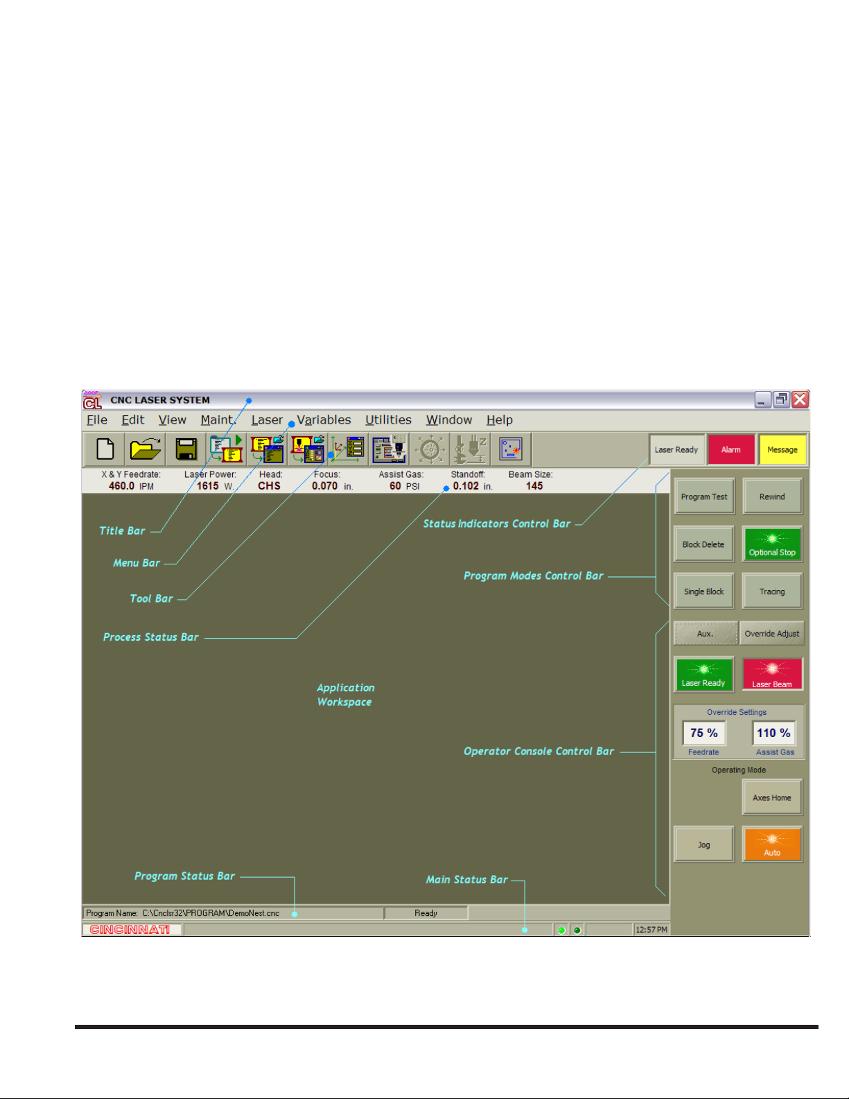
The Laser System Display window occupies the entire display screen on the operator control station. The main components
of the Laser System Display window are the Title Bar, Menu Bar, Tool Bar, Status Indicators Control Bar, Application
Workspace, Operator Console Control Bar, and Main Status Bar. A Process Status Bar, Program Modes Control Bar, and
Program Status Bar may also be visible, depending on the current operating mode of the Laser System.
7-1
EM-551 (N-04/11)
Page 12
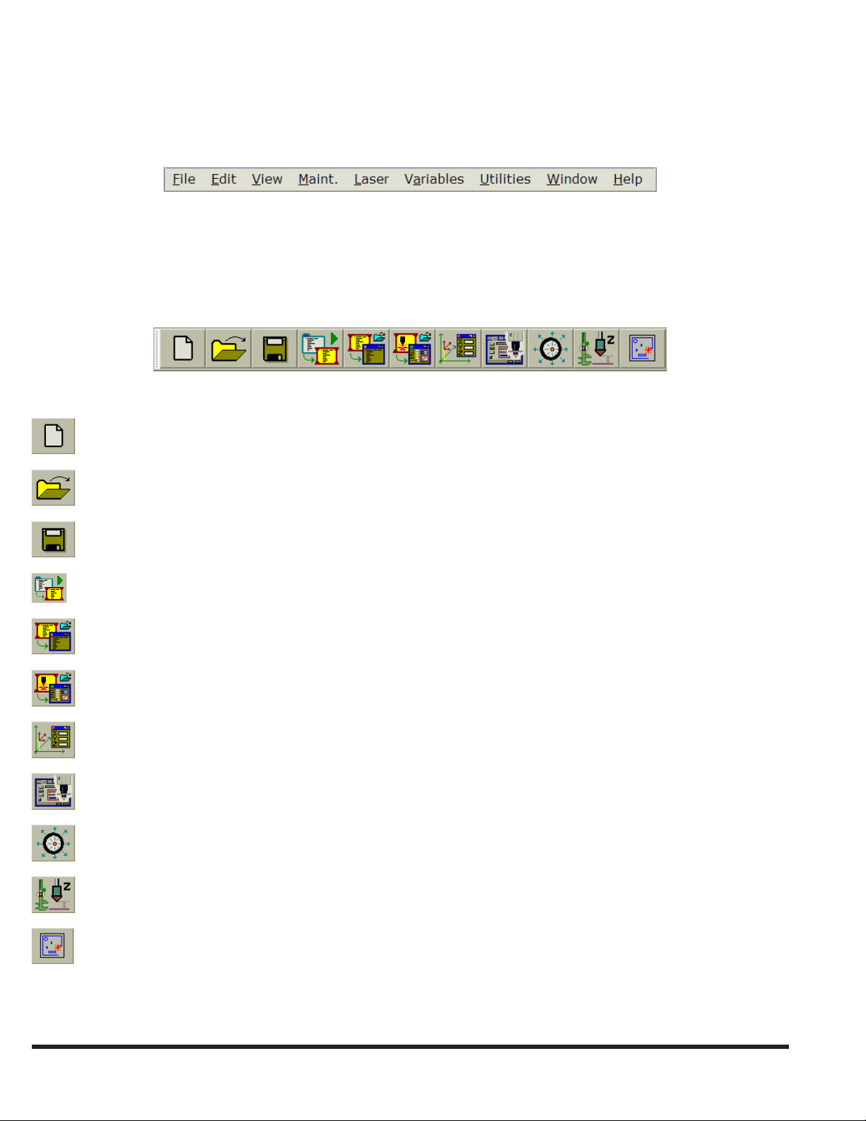
MENU BAR
The Menu Bar is the row of main menu titles across the top of the Laser System Display window. Selecting a menu title
opens a pop-up menu displaying a list of menu commands. See the MENU COMMANDS section for a description of each
command.
TOOL BAR
The Tool Bar, located below the Menu Bar, contains a row of buttons where each button corresponds to a menu command.
The Tool Bar provides convenient, single-touch access to some of the more commonly used menu commands. The Tool
Bar can be hidden or displayed by going to: View | Control Bars.
This list identies which menu command is associated with each Tool Bar button:
File | New
File | Open
File | Save
File | Load Current Program
File | Open Loaded Program
File | View Current Process
View | View Axes Positions
Utilities | Operator Setup
Utilities | Lens Centering Mode
Utilities | Standoff Calibration
Open the CINCINNATI Laser Programming and Nesting application, if installed.
EM-551 (N-04/11)
7-2
Page 13

STATUS INDICATORS CONTROL BAR
The Status Indicators Control Bar, which is normally positioned to the right of the Tool Bar, consists of separate indicators
for laser state: “alarm condition present” and “operator message ready”. The left-most indicator shows the current laser
operating state. Click or touch this indicator for a shortcut to open the Laser Status window. The “Alarm” indicator signies
the presence of system alarms or laser alarms when its color is red. A ashing red indicator means that one or more system
alarms are active. A solid red indicator means that only laser alarms are active. A yellow “Message” indicator signies
that one or more operator FYI messages are pending. Both the “Alarm” and “Message” indicators can be used as shortcut
buttons to open or close the Alarms and Messages window. The status indicators can be used as a shortcut to open or close
the Laser Status window.
PROCESS STATUS BAR
The Process Status Bar, which is located below the Tool Bar, displays critical process information such as feedrate, laser
power, beam focus position, assist gas pressure, and nozzle standoff. The Process Status Bar is only displayed when the
Laser System is in Auto mode. All displayed values are updated in real time. While the control is in Auto mode, the Process
Status Bar can be hidden or displayed by going to View | Control Bars | Process Status Bar.
APPLICATION WORKSPACE
The Application Workspace is the area (initially blank) which is below the Process Status Bar or Tool Bar and above the
Program Status Bar. NC program windows, Process Parameter windows, and all other user-activated windows and dialogs
will open in this area.
7-3
EM-551 (N-04/11)
Page 14
OPERATOR CONSOLE CONTROL BAR
The Operator Console Control Bar contains the user interface controls used by the machine operator to control and monitor
the basic operating mode of the Laser System. See OPERATOR CONSOLE in the CONTROL BARS section, for
information on this control bar.
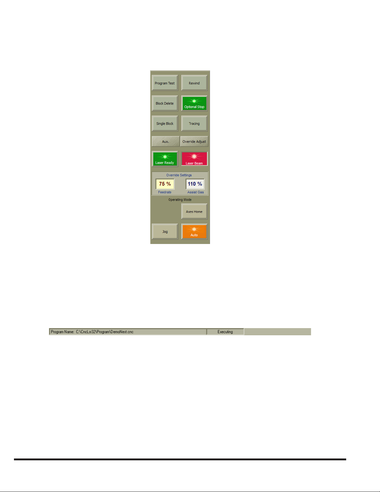
PROGRAM STATUS BAR
The Program Status Bar, located just below the Application Workspace, displays the cutting program execution status. Like
the Program Modes Control Bar and the Process Status Bar, this status bar is visible only when the control is in Auto mode.
The Program Status Bar is divided into two elds, the left eld contains the le name of the currently loaded NC program.
This eld is empty when there is no NC program loaded into the control. The right eld indicates the current state of the
program execution subsystem. For example: “Program not loaded”, “Executing”, or “Program Stopped” may be displayed
here.
MAIN STATUS BAR
The Main Status Bar is displayed at the bottom of the Laser Status Monitor window, and is used to display operator help
messages and other general information. The Main Status Bar is divided into several sections. The section to the right of
the CINCINNATI logo displays a brief description of Menu Bar and Tool Bar button commands as these items are selected
with the trackball or keyboard.
To the right of the command description is the laser control system “heartbeat” indicator. A properly functioning control
system is indicated by two alternately ashing green indicators. If either indicator stops ashing or turns red, power down
the system and restart it. If this does not return the indicators to their proper state, contact CINCINNATI INCORPORATED
Laser Service Department.
The next eld to the right is the NC Program le line number of the line where the cursor is currently located. This eld is
blank if an NC Program Edit window is not the currently active window.
EM-551 (N-04/11)
7-4
Page 15
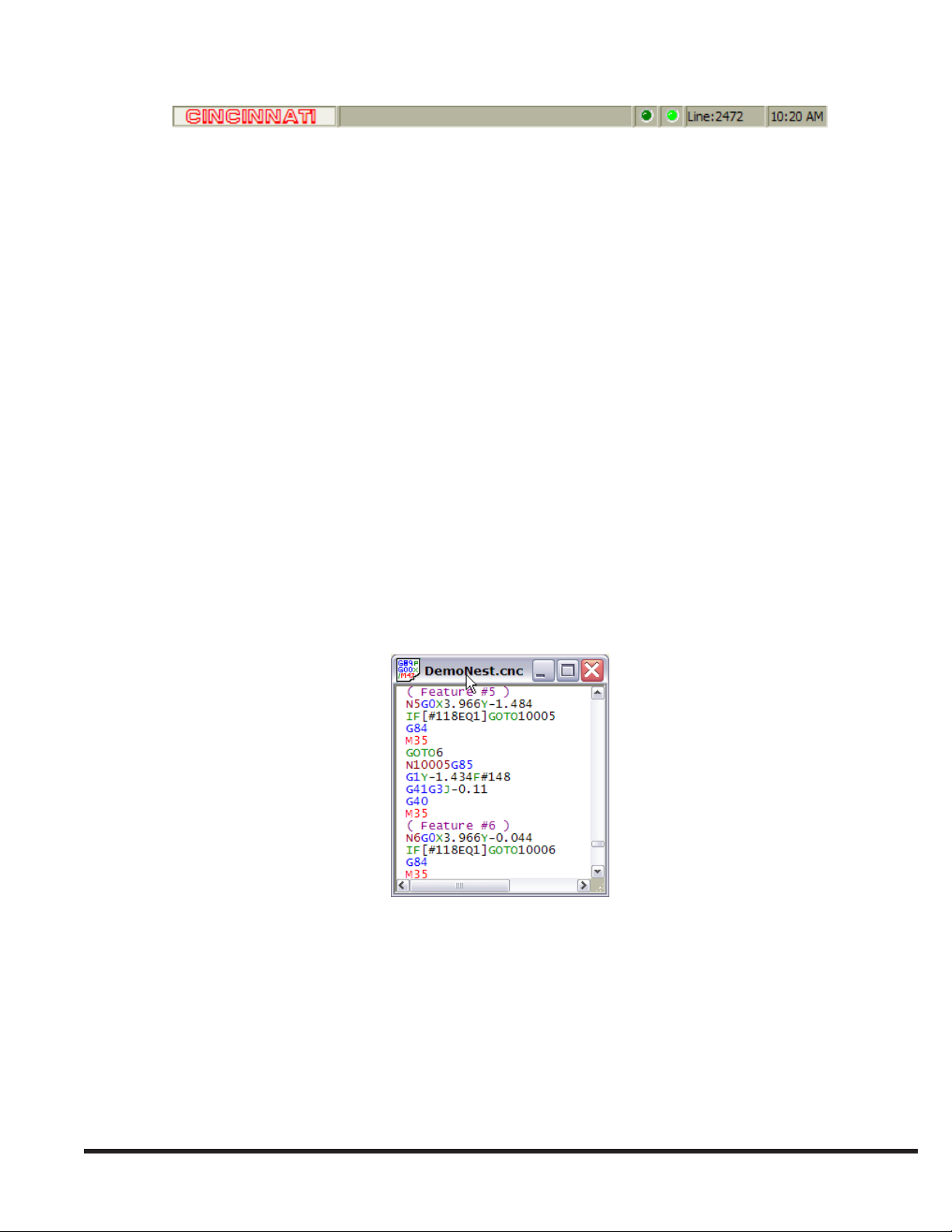
In the far right section of the Main Status Bar, the current time is displayed.
FILE TYPES
The Laser System control software gets the information it needs to execute cutting applications from two types of data les:
NC Program les and Process Parameter les. A third type of le, the Batch Program le, may be used if desired, to create
a list of NC Program les to be executed in the specied order.
The File menu commands and Tool Bar buttons, described later, can be used to open these les for viewing/editing, and to
create new les. When opening an existing le or creating a new le, a window will appear in the Application Workspace,
displaying the le’s contents. The Title Bar of each le view window contains the name of its le.
When a le is modied, it must be saved using File | Save or Tool Bar Save command before any changes will take effect.
An asterisk “*” will appear next to the le name of any le that has been modied but not saved.
The following topics describe each of the three types of le and their view windows.
NC PROGRAM FILE
The NC Program le contains the NC codes that determine the part feature geometry and control the various machine
cutting functions. NC programs, which may be as simple as a single part or as complex as multiple sheets of nested parts,
are typically generated by nesting/post-processing software packages such as the CINCINNATI Laser Programming
and Nesting Software application. NC Program le names should end with “.cnc” (ex: “Filename.cnc”).
When an NC Program le is opened, its contents are displayed in a Program Edit window. Program Edit windows use
context coloring; distinct program components are displayed with different colors (G codes are blue, M codes are red,
etc).
PROCESS PARAMETER FILE
The Process Parameter le contains settings used to control the power and focusing attributes of the laser beam and the
cutting assist gas. Process Parameters are stored in multiple les, with a separate le for each distinct cutting process. All
CINCINNATI Laser Systems are shipped with a library of Process Parameter les containing the cutting parameter settings
recommended by CINCINNATI INCORPORATED. These les are stored in the “Cnclsr32/Material” folder on the laser
control’s computer hard disk drive. These les can be modied to specify other cutting processes by creating new Process
Parameter les with the preferred settings. Process Parameter le names should end with “.lib” (ex: “Filename.lib”).
G89 blocks in the NC Program le specify which Process Parameter le(s) will be used in each cutting application. See
CUSTOM G CODES in the LASER NC PROGRAMMING topic for more information on G89.
7-5
EM-551 (N-04/11)
Page 16
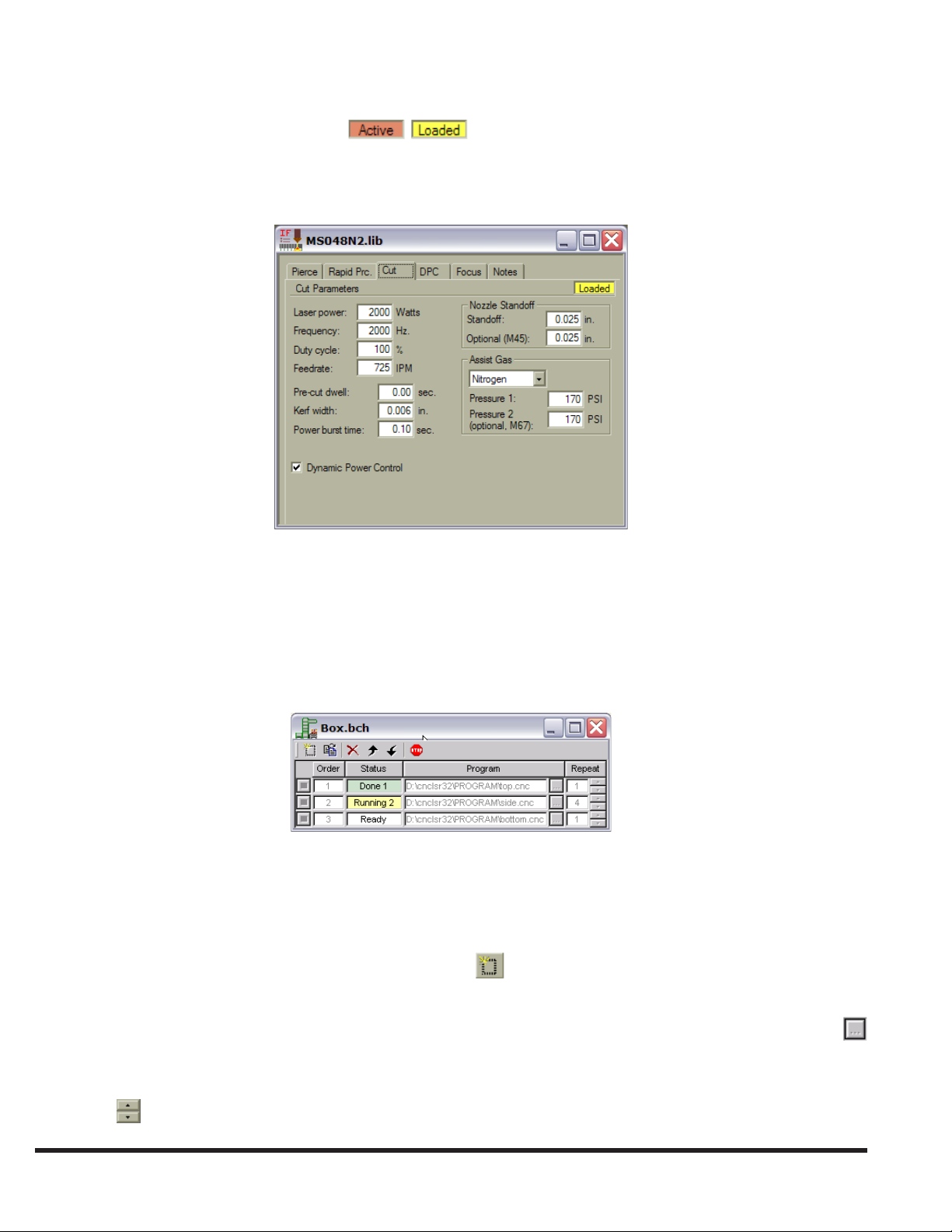
When a Process Parameter le is opened, the parameter settings are displayed in a Process Parameter window. See the
CUTTING PROCESS PARAMETERS topic for more information on process parameters.
Note: An “Active” or “Loaded” indicator: may be displayed in the upper right corner of the Process
Parameter window. If a Process Parameter le that is loaded via a G89 block anywhere in the active NC program
is open in a window, a yellow “Loaded” indicator will be displayed. If this le represents the currently active
cutting process, then an orange “Active” indicator will be displayed.
BATCH PROGRAM FILE
A Batch Program le is a list of NC Program les that will be loaded and executed in the order listed. It allows programs
to be grouped together in a logical manner and allows the control to keep track of which programs have been completed
and which program to load next. A Batch Program can contain up to one hundred program entries and each entry can be
repeated up to one hundred times. Batch Program le names should end with “.bch” (ex: “Filename.bch”).
When a Batch Program le is opened, the parameter settings are displayed in a Batch Program window:
Creating a Batch Program
To create a new Batch Program:
Select 1. File | New and then select “Batch” le type in the New Selection window. Click “OK” to close the New Selection
window.
In the new 2. Batch Program window, select the “New Entry” button until the window has enough rows for all NC
programs that will be added to the batch.
In each row, enter the NC Program le name in the 3. Program column by typing it directly or using the “Browse”
button to select it with the trackball.
Enter the number of times that each program will run in the 4. Repeat column by typing it directly or by using the arrow
buttons .
EM-551 (N-04/11)
7-6
Page 17
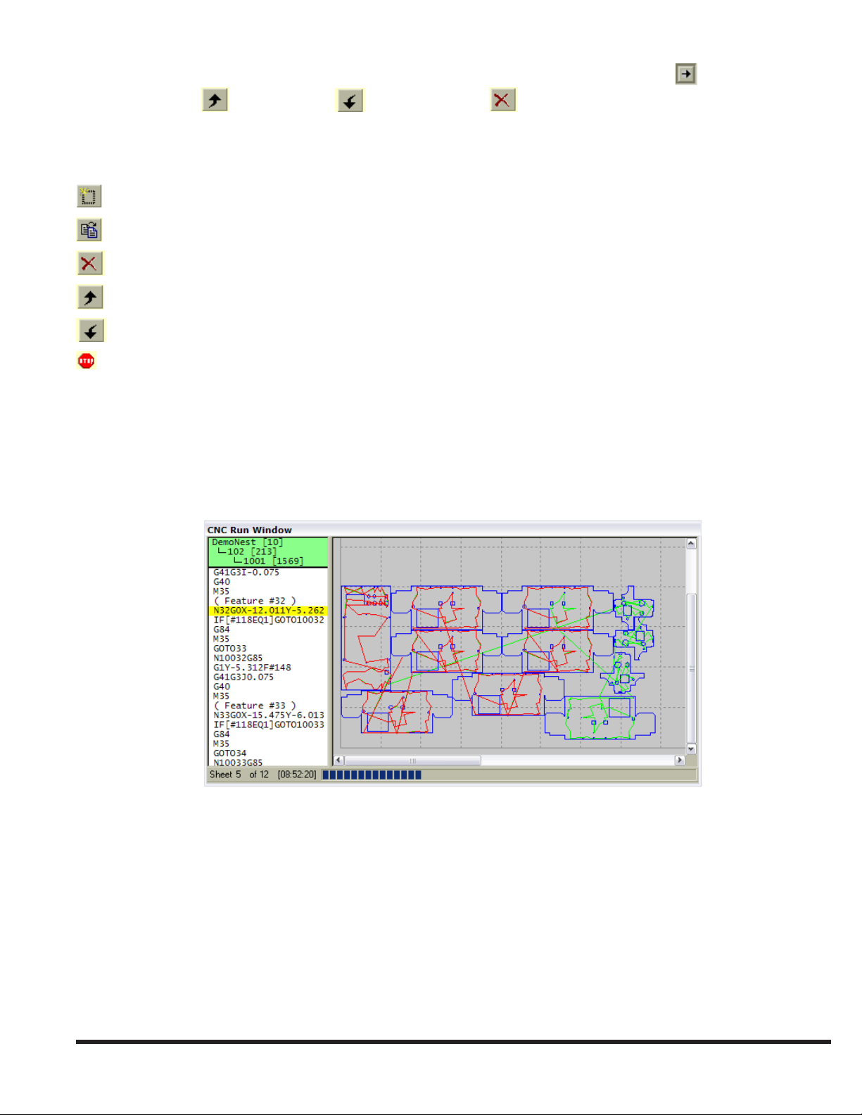
If it becomes necessary to move or delete an entire row, select the row using the “Row Select” 5. button and then press
the “Move Up” , “Move Down” , or “Delete Entry” button.
Editing a Batch Program
Batch Program editing functions are provided in the Batch Program window. The editing functions are:
Insert new row Inserts a new NC Program le entry after the selected entry or at the end of the list.
Copy a row Copies the selected row and inserts the copy into the list after the selected row.
Delete Entry Deletes the selected entry.
Move Up Moves the selected entry up one row in the list.
Move Down Moves the selected entry down one row in the list.
Stop the Batch Stops a running Batch Program.
CNC RUN WINDOW
The CNC Run Window displays the execution status of the active cutting program, if a program is currently loaded. This
window cannot be manually opened or closed. The control software will automatically display the CNC Run Window
each time a part program is successfully loaded, and whenever the control enters Auto mode while a program is loaded.
Likewise, the CNC Run Window will automatically close whenever the control enters Jog mode or Axes Home mode.
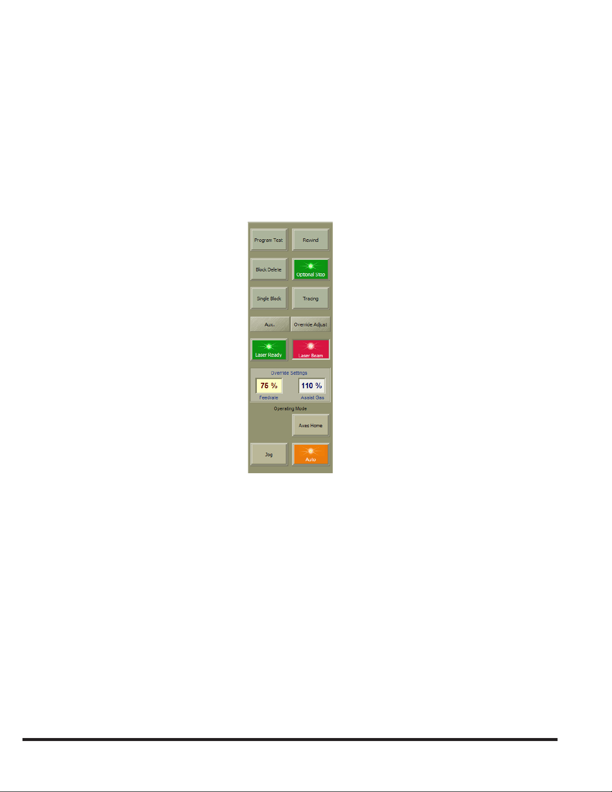
The CNC Run Window has two sections and a status bar. The left section displays the NC program code with the active
block highlighted. To help locate the current position in an interrupted cutting program, the active subroutine name and
line number are displayed in a green box at the top of the NC code section. All currently active subroutines are displayed,
indented to the right to indicate the nesting depth for nested subroutines.
The right section is a graphical plot of the current sheet program. For each sheet, the status bar at the bottom of the window
displays the sheet number, the remaining runtime, and a bar graph showing the percentage of completed program blocks.
The plotting software interprets M50 as the start of another sheet.
Before the program starts each sheet, the plot shows all X-axis and Y-axis rapid moves in green. Contouring moves with the
laser beam on are shown in blue. Contouring moves with the laser beam off are shown in yellow. As the program runs, the
plot changes the color of all completed moves to red. To change the width of the plot section, select the divider between the
left and right sections and drag it to another location. To change the viewing area of the plot, use any of the various Zoom
7-7
EM-551 (N-04/11)
Page 18
features. See WINDOW ZOOMING in the VIEW MENU section.
If desired, the plot section and status bar can be hidden, resulting in a much smaller CNC Run Window. See RUN WINDOW
GRAPHICS in the VIEW MENU section.
CONTROL BARS
OPERATOR CONSOLE
The Operator Console Control Bar contains four different groups of user controls: Program Modes, Laser Resonator,
Override Settings, and Operating Mode. There are also two buttons that can be used to quickly open or close other control
bars.
Selecting the “Aux.” button will open the Auxiliary Functions Control Bar if it is not currently open, or close it if it is
currently open. Selecting the “Override Adjust” button will open the Override Adjust Control Bar if it is not currently open,
or close it if it is currently open.
PROGRAM MODES
The top section of the Operator Console Control Bar contains controls that turn on or off the various program execution
modes that affect how the control software executes NC programs. Each control is both a button and indicator for the
corresponding mode. Like the button/indicators in the other control bars, these controls appear bright green (ON) when the
corresponding mode is active, and dull green or gray (OFF) when the mode is not active.
The Laser Control Software automatically displays the Program Modes Control Bar each time the CNC control enters Auto
mode. When the control enters Jog or Axes Home mode from Auto mode, this control bar will automatically close.
EM-551 (N-04/11)
7-8
Page 19
PROGRAM TEST MODE
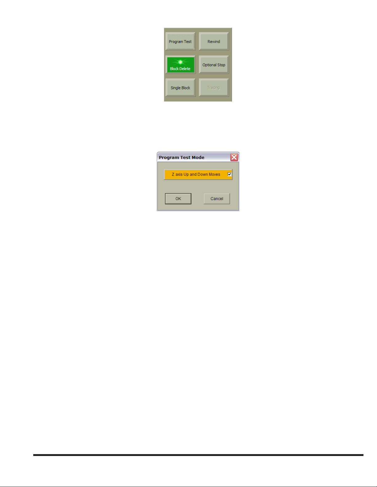
Program Test Mode will run a part program without actually cutting material. Use the “Program Test” button to activate
Program Test Mode. In this mode, the laser beam and assist gas will not turn on during program execution. Selecting the
“Program Test” button when Program Test Mode is off will cause the ‘Program Test Mode’ dialog box to open.
The “Z-axis Up and Down Moves” button enables or disables Z-axis motion while Program Test Mode is active. If the
box is not checked, the cutting head will not move up or down, and the program will ignore the Pierce dwell. Select “OK”
to close the dialog and activate Program Test Mode; select “Cancel” to close the dialog without activating Program Test
Mode.
Keyboard Shortcut: F2
REWIND
The “Rewind” button sets the rst block of the active NC program as the next block to be executed when “CYCLE
START” is pressed. Use this function to restart the program from the beginning when program execution is interrupted. The
“Rewind” button is disabled while program execution is in progress. Note that this button does not stay in the green (ON)
state when selected, since it does not make a new mode active.
Keyboard Shortcut: F3
BLOCK DELETE MODE
While Block Delete mode is active, any block in the NC program that begins with the “ / ” (forward slash) character will
not be executed. The “Block Delete” button activates Block Delete mode. Block Delete mode can be enabled/disabled at
any time during program execution.
Keyboard Shortcut: F4
OPTIONAL STOP MODE
Optional Stop mode enables the use of M01 (or M1) in a program. Use the “Optional Stop” button to activate Optional
Stop program execution mode. When Optional Stop mode is active, the control changes to the Cycle Stop condition when
a program commands M01. Program execution resumes when “CYCLE START” is pressed. Optional Stop mode can be
enabled/disabled at any time during program execution.
Keyboard Shortcut: F5
7-9
EM-551 (N-04/11)
Page 20
SINGLE BLOCK MODE
In Single Block mode, only one NC Program block will be executed each time “CYCLE START” is pressed. The “Single
Block” button activates Single Block program execution mode.
Keyboard Shortcut: F6
TRACE MODE
The “Tracing” button activates program execution Trace mode. When Trace mode is active, the “TRACE FORWARD” and
“TRACE REVERSE” buttons on the machine operator front panel are enabled. Tracing is used to recover from program
interruptions; it allows the operator to step through the program in either the forward or reverse direction with the laser
beam off, as long as the “TRACE FORWARD” or “TRACE REVERSE” button is pressed. See ERROR RECOVERY in
the CUTTING PROCEDURES section.
Keyboard Shortcut: F7
Note: There is a limit to how far in reverse a program can be traced. As a program is running, a xed number of executed
program blocks are held in memory. This memory area, known as the “history buffer”, limits how far a program
can be traced in reverse. Large programs may contain more blocks than the history buffer can hold. Attempts to
trace backwards beyond the last block in the history buffer will cause the alarm “End of history buffer or beginning
of program reached. Reverse tracing is disabled.”
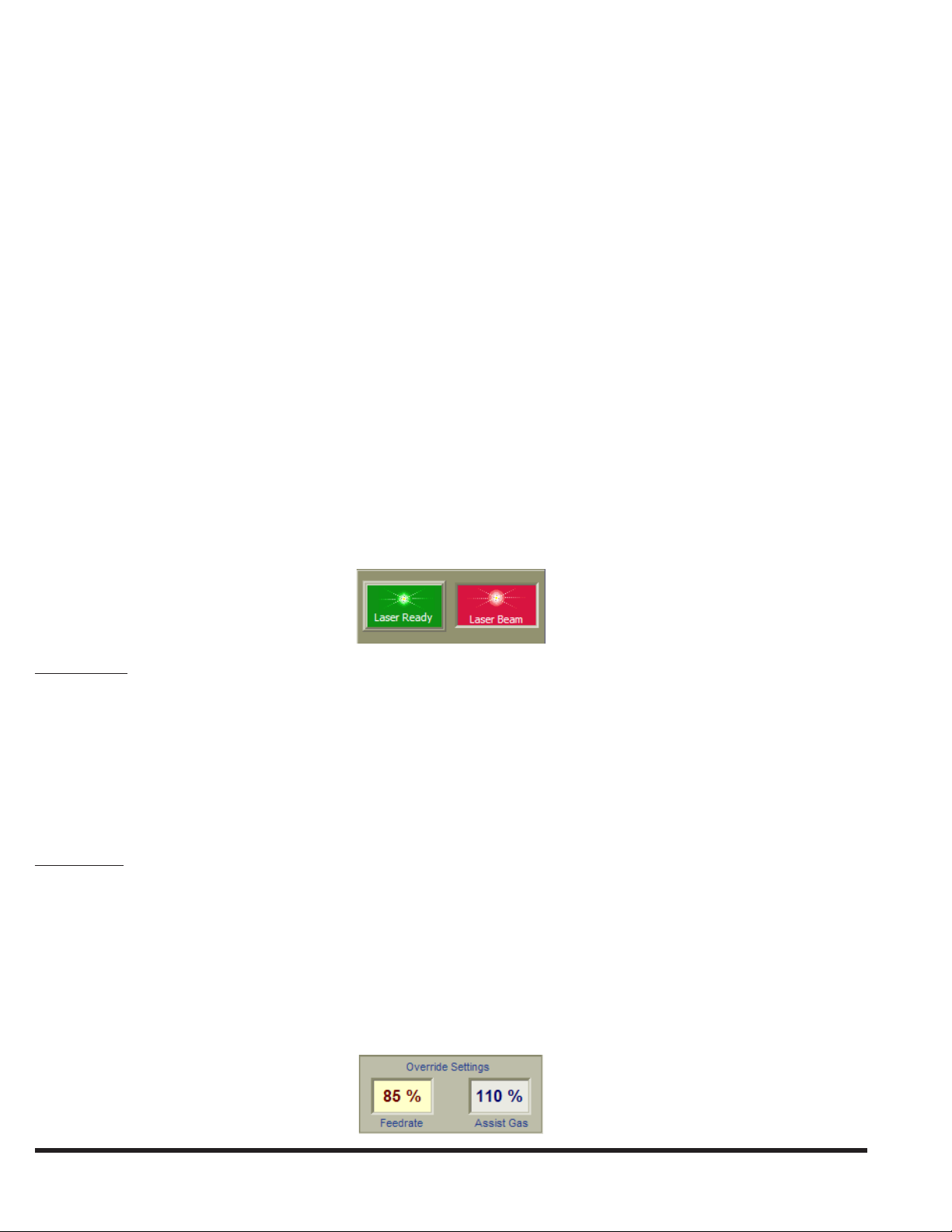
LASER CONTROLS
This part of the Operator Console Control Bar contains controls related to the laser.
Laser Ready: The “Laser Ready” button/indicator will appear bright green (ON) when the laser has nished its start up
sequence and is ready to turn the beam on, and dull green or gray (OFF) when the laser is not ready to turn the beam
on. If the “HIGH VOLTAGE” keyswitch on the Machine Operator Side Panel is in the LOCKED position, the indicator
will be appear off, displaying an image of a padlock.
Selecting this button when Laser Ready is off commands the control to connect power to the laser main power supply,
initiating the power-up sequence. During the power-up sequence, the indicator blinks on and off; when the power-up
sequence is complete, the indicator will remain on. Selecting this button when Laser Ready is on commands the control
to remove electrical power from the laser main power supply.
Laser Beam: This indicator displays the On/Off status of the laser beam. The “Laser Beam” indicator is red (ON) when
the laser is producing a beam. The laser produces a beam in response to requests for laser power. Laser power can be
requested by the cutting program or by the Lens Centering function. When the laser is not producing a beam, the
indicator color is dull red or gray (OFF).
OVERRIDE SETTINGS
In the center section of the Operator Console Control Bar, the current values of the Jog/Feedrate and Assist Gas Override
settings are displayed.
EM-551 (N-04/11)
7-10
Page 21
It is easy to change either override setting by selecting one of the override display boxes. This will cause the Override
Adjust Control Bar to open. Once selected, that display box will change to a red text/yellow background color to indicate
that the corresponding override is activated for adjustment in the Override Adjust Control Bar.
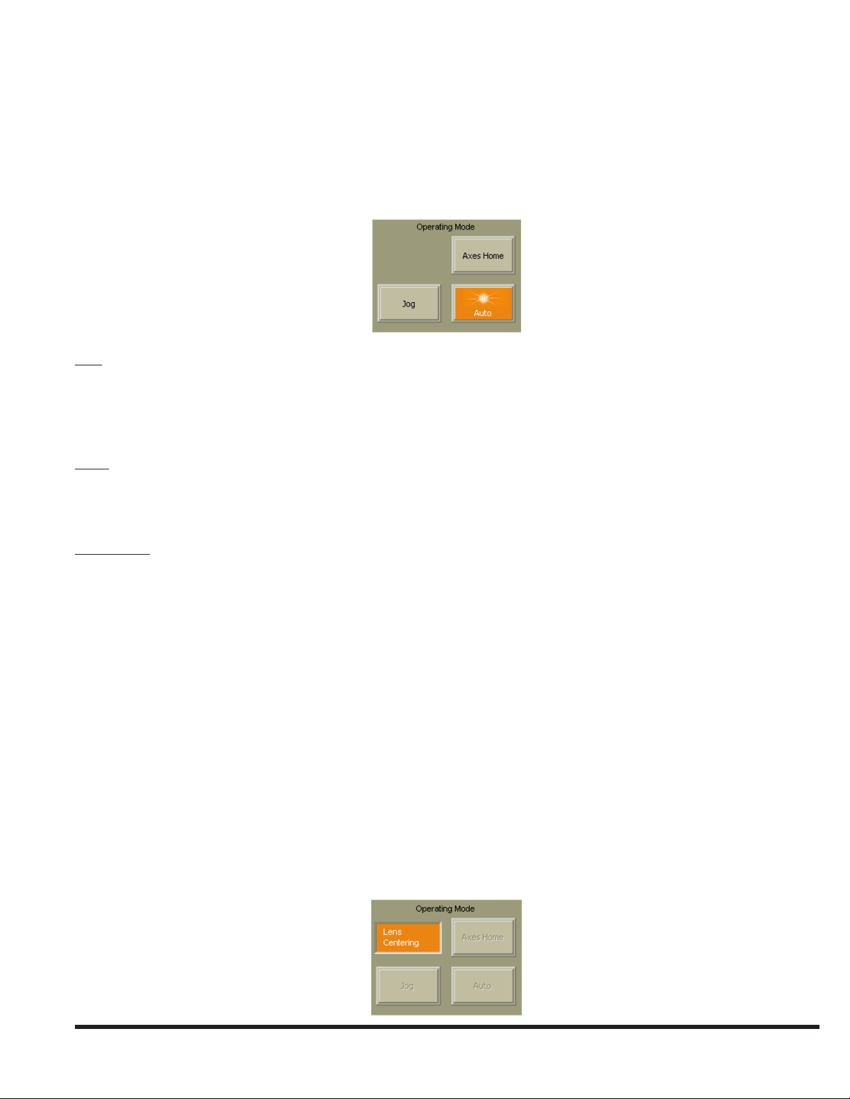
OPERATING MODES
The bottom section of the Operator Console Control Bar contains three button/indicator controls for the primary operating
mode, and an “Alternate Mode” indicator.
Jog: This button/indicator activates Jog mode. While the control is in Jog mode, the “Jog” indicator color is amber. In
Jog mode, the axis motion controls on the Operator Control Station front panel or the Remote Station can be used to
manually move (“jog”) each machine axis individually. Cutting program execution is disabled while Jog mode is active.
Most Maint. | Utilities functions, such as Lens Centering, are only enabled when the Laser System is in Jog mode. The
control will remain in Jog mode until another mode is selected.
Auto: This button/indicator activates Auto mode. The Laser System must be in Auto mode in order to run cutting programs.
While the control is in Auto mode, the “Auto” indicator color is amber, and most Maint. | Utilities functions, are
disabled. The NC Program les and Process Parameter Files while the control is executing a program in Auto mode. The
control will remain in Auto mode until another mode is selected.
Axes Home: This button/indicator activates Axes Home mode. When selected, the “Axes Home” button text changes to
“Homing” and the color changes to amber. To home the axes, the main drives must be on with no system alarms present.
The Axes Homing function begins when the operator presses the “CYCLE START” pushbutton. When all axes have
moved to their reference positions, all axis motion stops, the Axes Home function ends and the control automatically
changes to Jog mode.
Special Operating Mode
Special Operating Modes are alternate modes the Laser System is in while certain functions are active:
Lens Centering•
Standoff Calibration•
Note: The Laser System must be in Jog mode before a “Special Operating Mode” can be activated.
Special operating modes are typically modes in which the “CYCLE START” / “CYCLE STOP” buttons perform some
unique function other than starting the execution of a cutting program. For example, Standoff Calibration is a “Special
Operating Mode” since “CYCLE START” initiates the Noncontact Head standoff calibration sequence. When any of these
special operating modes are active, the amber-colored “Alternate Modes” indicator will be visible, and the three primary
operating mode buttons will be disabled.
7-11
EM-551 (N-04/11)
Page 22
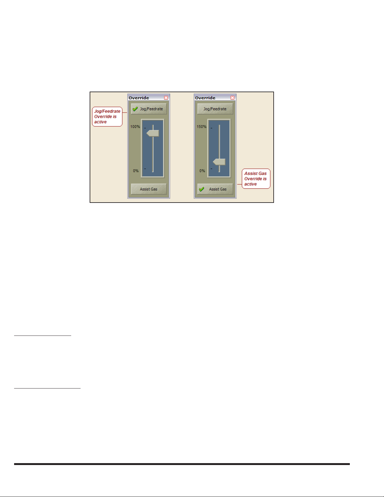
OVERRIDE ADJUST
The Override Adjust Control Bar contains a slider control that can be used to adjust the setting of either the Jog/Feedrate
Override or the Assist Gas Override function. Only one override setting, the active override, is adjusted at a time. The
active override is selected by selecting either the “Jog/Feedrate” or the “Assist Gas” button. The currently active override
is indicated by a green check mark on the corresponding button and a yellow background color for the “Override Settings”
indicator in the Operator Console Control Bar.
The Override Adjust Control Bar can be opened/closed in any of the following ways:
Select the “Override Adjust” button in the Operator Console Control Bar.•
▪ Select either “Override Settings” indicator in the Operator Console Control Bar; this will also make the corresponding
override active.
Go to: • View | Control Bars | Overrides
There are several ways to change the slider control setting in the Override Adjust Control Bar:
After selecting the slider control, the “Page Up” and “Page Down” keyboard keys will change the setting in 5% •
increments.
The “Up Arrow” and “Down Arrow” keyboard keys change the setting in 1% increments.•
Select the “Slider Control” indicator with the trackball pointing device and then drag it to any setting.•
Rotate the wheel on the trackball pointing device after selecting the slider control. •
Assist Gas Override: This setting modies the programmed assist gas pressure used for cutting. For example, if the program
species 200 PSI and the assist gas override is set to 75%, the actual cutting pressure will be: 75% of 200 PSI = 150 PSI.
This setting also affects the pressure achieved when assist gas is manually activated using one of the assist gas buttons
on the Auxiliary Functions Control Bar. The assist gas override setting is adjustable from 0% to 150%.
Note: The Assist Gas Override setting does not affect the assist gas pressure used when piercing.
Jog/Feedrate Override: When the NC cutting program commands the X-axis and/or Y-axis to a position with a G01,
G02, or G03 block, the actual feedrate will be the percentage of the commanded feedrate specied by the Jog/Feedrate
Override setting. For example, if Jog/Feedrate Override is set to 75% and the program species “F400”, the actual
feedrate will be 75% of 400 IPM = 300 IPM. The Jog/Feedrate Override setting is adjustable from 0% to 100%. The
Feedrate Override is disabled during rapid moves (G0) or when M48 is active.
Jog/Feedrate Override also changes the jogging speed of the X- and Y-axes when the “RAPID TRAVERSE” button
is not lit. The jogging speed at 100% is the “X/Y-axis Jog Speed” specied on the General page of the Maintenance/
Machine Conguration window (300 IPM or 7620 mm/min typical).
EM-551 (N-04/11)
7-12
Page 23
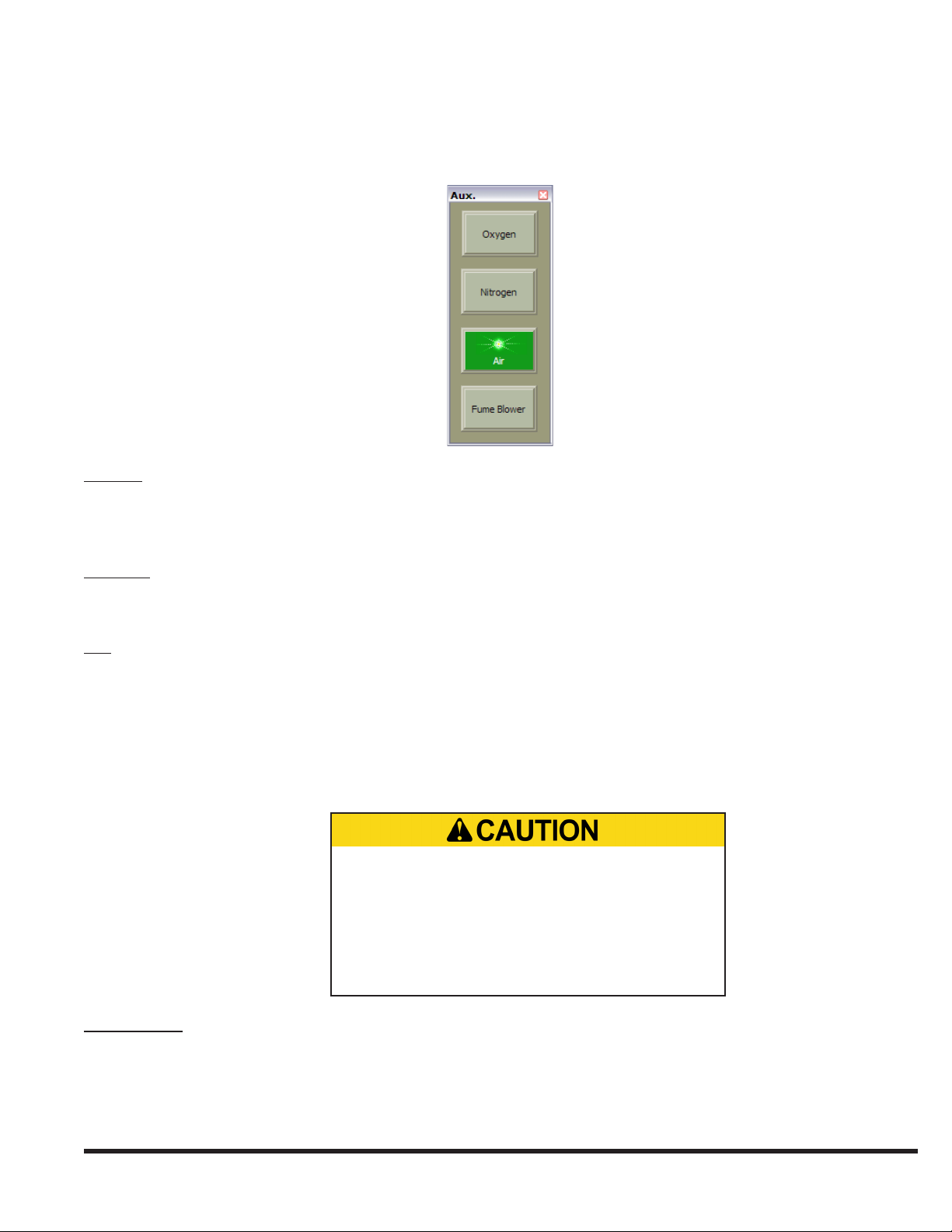
AUXILIARY FUNCTIONS
The Auxiliary Functions Control Bar contains buttons for manually activating assist gas ow and the fume blower system.
Open/close this control bar by selecting the “Aux.” button on the Operator Console Control Bar, or by selecting View |
Control Bars | Aux.
Oxygen: This control is both a manual activation button and indicator for oxygen assist gas. When executing a cutting
program, the control automatically commands assist gas ow through the nozzle. When oxygen assist gas is owing,
the “Oxygen” indicator color changes from dull green or gray (OFF) to bright green (ON). This button is used in Jog or
Auto mode to manually control the oxygen assist gas solenoid valve.
Nitrogen: This control is both a manual activation button and indicator for nitrogen assist gas. When nitrogen assist gas is
owing, the “Nitrogen” indicator color changes from dull green or gray (OFF) to bright green (ON). This button is used
in Jog or Auto mode to manually control the nitrogen assist gas solenoid valve.
Air: This control is both a manual activation button and indicator for air assist gas. When air assist gas is owing, the “Air”
indicator color changes from dull green or gray (OFF) to bright green (ON). This button is used in Jog or Auto mode to
manually control the air assist gas solenoid valve.
Note: Only one assist gas can be active at a time. If nitrogen is owing when the oxygen button is selected, the nitrogen
gas solenoid will close and the oxygen gas solenoid will open, etc.
Verify correct installation of lens drawer and
nozzle tip before activating either assist gas
solenoid valve. Applying assist gas pressure
without proper installation of these parts can
force the lens drawer or nozzle tip out of position
or out of the cutting head. Unrestricted ow can
also damage assist gas supply components.
Fume Blower: This a manual activation button and indicator for the fume blower. Selecting this button toggles the fume
blower on or off when the program is not running. The fume blower turns on automatically when the machine is cutting.
When the program ends, the fume blower remains on for 60 seconds, plus the Blower OFF delay time specied on the
Auxiliary page of the Conguration window, and then turns off automatically. This button is used to provide additional
fume removal time. The “Fume Blower” indicator color is dull green or gray (OFF) when the fume blower is off and
bright green (ON) when the fume blower is running.
7-13
EM-551 (N-04/11)
Page 24
MENU COMMANDS
FILE MENU
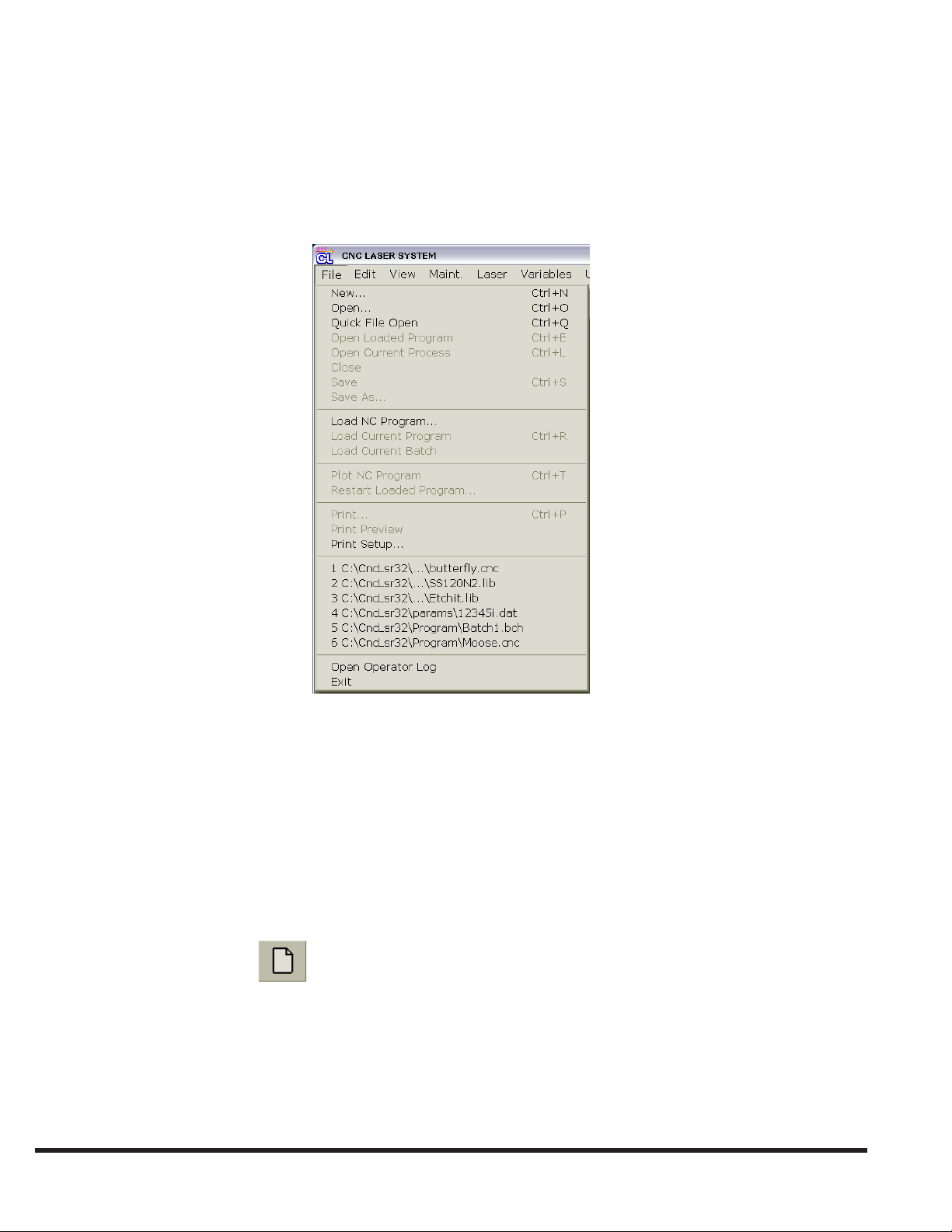
In the File menu, various commands can be used to manage les and to activate le-related functions. Many of the File
menu commands, such as Open, Save, and Print, are standard commands used by most Microsoft Windows applications,
while others are for Laser System-specic functions: Open Current Process, Load Current Program, etc.
NEW
File | New creates a new le and opens a new window displaying the les contents. The Laser System software works
with three different types of data les (see FILE TYPES). Before a new le is generated, the ‘New File’ dialog box opens,
prompting the user to specify the type of le to create. The following types of le can be created::
NC Program File•
Process Parameter File•
Batch Program File•
Toolbar Shortcut:
Keyboard Shortcut: Ctrl + N or { Alt, F, N } sequence
OPEN
File | Open opens an existing laser le in a new window. Multiple le windows of all types can be open at the same time.
This command causes the File Open window to appear. Use this window to select a le to open.
EM-551 (N-04/11)
7-14
Page 25
Note: Use the Most Recently Used (MRU) File List to quickly reopen a le that was recently closed. See the MRU FILE
LIST section for more information.
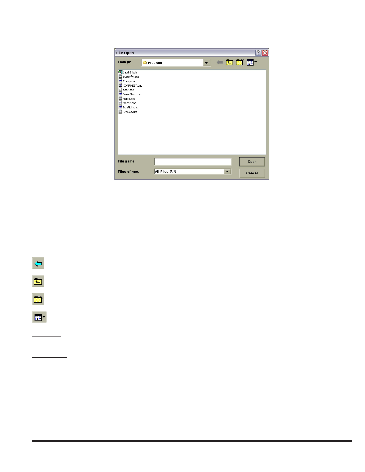
Use these controls in the File Open window to identify the le to be opened:
Look In: Displays the name of the folder whose contents are displayed in the browser box below. To see how the current
folder ts in the folder hierarchy, select the down arrow. To see what is inside a folder, select the folder.
File Browser: This is the large box below the “Look In” eld that lists the folders and les in the folder specied in the
“Look In” eld. Use the browser to graphically select a le or a different folder. Double-clicking a folder will cause its
contents to be displayed in the browser and its name to appear in the “Look In” eld. The buttons above the browser
window can be used to nd and select folders and les:
Navigate the browser to the previously selected folder.
Navigate the browser to the folder one level higher than the currently displayed folder.
Create a new folder.
Change the browser view mode.
File name: Type the name of the le to be opened here or use the browser window to graphically select the le to open.
Selecting a le in the browser window will cause its name to appear in the “File name” eld.
Files of type: Lists the types of les to display in the browser. The choices are:
All Files•
NC Program File (with • .cnc extension)
Process Parameter Files (with • .lib extension)
Batch Files (with • .bch extension)
Note: Only les with the extension listed in the “Files of Type” drop-down list are shown in the browser window.
7-15
EM-551 (N-04/11)
Page 26
Toolbar Shortcut:
Keyboard Shortcut: Ctrl + O or { Alt, F, O } sequence
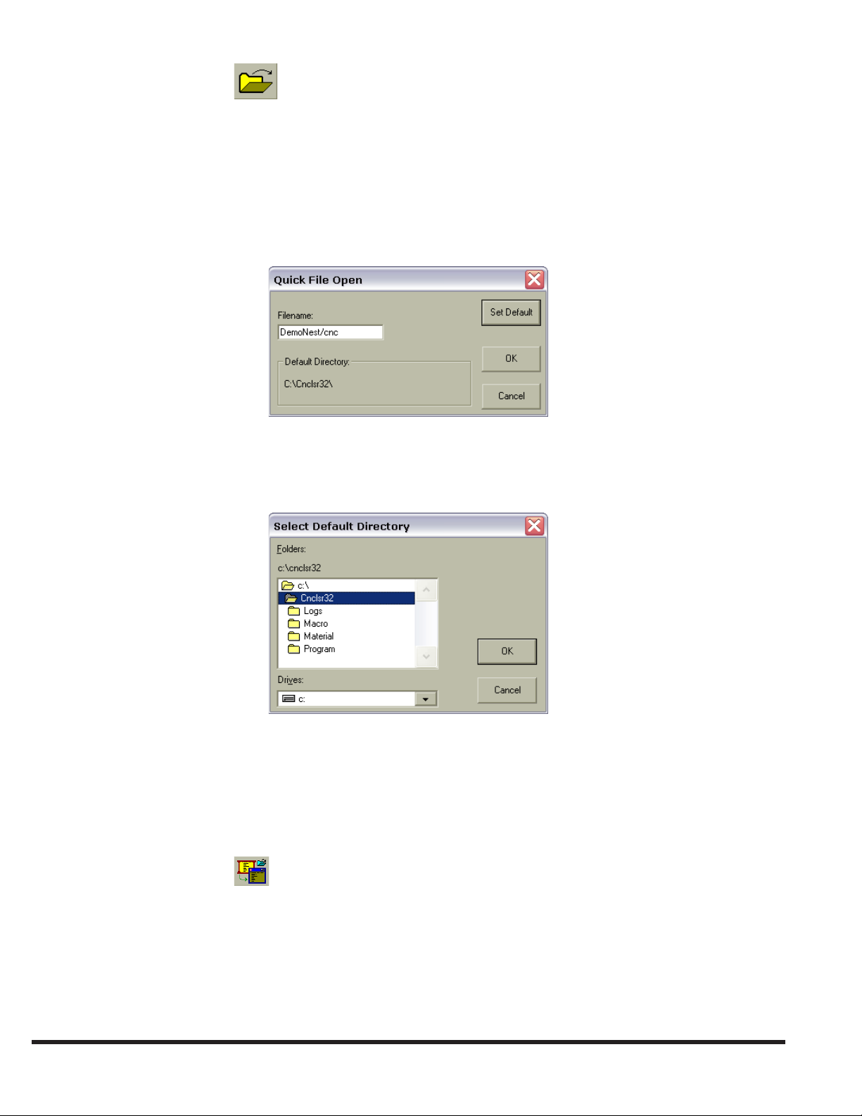
QUICK FILE OPEN
File | Quick File Open opens existing NC Program, Process Parameter, or Batch Program les. The Quick File Open
command will display the Quick File Open window. The name of the le to be opened is typed in the “Filename” eld. The
le must be located in the directory indicated in the ‘Default Directory’ box.
The “OK” button will open the le specied and close the Quick File Open window. The “Cancel” button will close the
Quick File Open window without opening a le. The “Set Default” button will open the Select Default Directory window
that will allow the user to select a new default directory. Once selected, this default directory will be saved and used until
a new selection is made.
Keyboard Shortcut: Ctrl + Q or { Alt, F, Q } sequence
OPEN LOADED PROGRAM
File | Open Loaded Program opens a window displaying the NC Program le currently loaded for execution. If no cutting
program is currently loaded, this command is disabled
Toolbar Shortcut:
Keyboard Shortcut: Ctrl + E
OPEN CURRENT PROCESS
File | Open Current Process opens a new window displaying the Process Parameter le currently being used for cutting.
If no cutting program is currently loaded for execution, this command is disabled.
EM-551 (N-04/11)
7-16
Page 27
Toolbar Shortcut:
Keyboard Shortcut : Ctrl + L
CLOSE
File | Close closes the active le. If the open le contains unsaved changes, the user will be prompted to save the changes
before closing the le. If a le is closed that has not been named, the Save As window will open rst, prompting the user
to name the le before closing it.
Note: If a le is closed without saving it, all changes made since the last time the le was saved will be lost.
Keyboard Shortcut: Ctrl + F4 or { Alt, F, C } sequence
“X” button on the window’s caption bar :
SAVE
File | Save saves any changes to the active le. The contents of the le will be written to its current location with its current
le name. When a new le is saved for the rst time, the Save As window will open rst, prompting the user to name the
le.
Toolbar Shortcut:
Keyboard Shortcut: Ctrl + S or { Alt, F, S } sequence
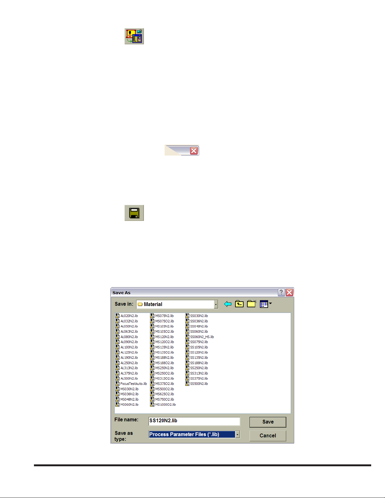
SAVE AS
File | Save As saves a new le with the specied name, or saves the contents of the active le to a different name and/or
location. This command causes the Save As window to open. Use this window to specify the le name and location.
Use these controls in the ‘Save As’ dialog box to specify the name of the le and its location:
7-17
EM-551 (N-04/11)
Page 28
Save in: Displays the name of the folder whose contents are displayed in the browser box below it. To see how the current
folder ts in the folder hierarchy, select the down arrow. To see what is inside a folder, select the folder.
File Browser: This is the large box below the “Save in” eld that lists the folders and les in the folder specied in the
“Save In” eld. Use the browser to graphically select a le or a different folder. Double-clicking a folder will cause its
contents to be displayed in the browser and its name to appear in the “Save in” eld. The buttons above the browser
window can be used to nd and select folders and les:
Navigate the browser to the previously selected folder.
Navigate the browser to the folder one level higher than the currently displayed folder.
Create a new folder.
Change the browser view mode.
File name: Enter the le name here or use the browser window to graphically select an existing le name. Selecting a le in
the browser window will cause its name to appear in the “File name” eld. If the le name entered here has no extension,
the extension listed in the “Save as type” drop-down list will be automatically added to the le name when it is saved.
Save as type: Species the type of le being saved. The list automatically includes the le type corresponding to the
document in the active window as the default type. For example, if the active window is a Process Parameter le, the
box will list “Process Parameter Files (*.lib)” as the le type.
Note: Only les with the extension listed in the “Files of Type” drop-down list are shown in the browser window.
Keyboard Shortcut: { Alt, F, A } sequence
LOAD NC PROGRAM
File | Load NC Program allows the user to specify an NC Program le to load into program execution memory. Each
program must be loaded into memory before it can be run. Once a program is loaded, it can be run multiple times without
being loaded again. Note that only one program can be loaded at a time. This command opens the Load NC Program
to Execute window, from which box to select a le to load. The Load NC Program to Execute window is similar to the
window used to open a le. See the OPEN topic in the FILE section for help with using this window.
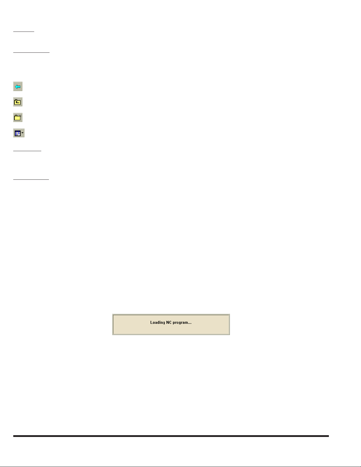
Some very large cutting programs may require several seconds to load. The following message window will be displayed
while the control is busy loading a program:
Note: The Laser System user interface is disabled until the control nishes loading the program.
Keyboard Shortcut: { Alt, F, L } sequence
LOAD CURRENT PROGRAM
File | Load Current Program loads the NC Program in the currently active Program Edit window into program execution
memory. This command is enabled only when an NC Program le is open in the currently active window. Each program
must be loaded into memory before it can be run. Once a program is loaded, it can be run multiple times without being
loaded again. Note that only one program can be loaded at a time.
Some very large cutting programs may require several seconds to load. The following message window will be displayed
EM-551 (N-04/11)
7-18
Page 29

while the control is busy loading a program:
Note: The Laser System user interface is disabled until the control nishes loading the program.
Toolbar Shortcut:
Keyboard Shortcut: Ctrl + R
LOAD CURRENT BATCH
File | Load Current Batch loads the currently open Batch Program le for execution. This command is enabled only
when a Batch Program le is open in the currently active window. See the BATCH PROGRAM FILE topic in the FILES
TYPES section for more about Batch Program les.
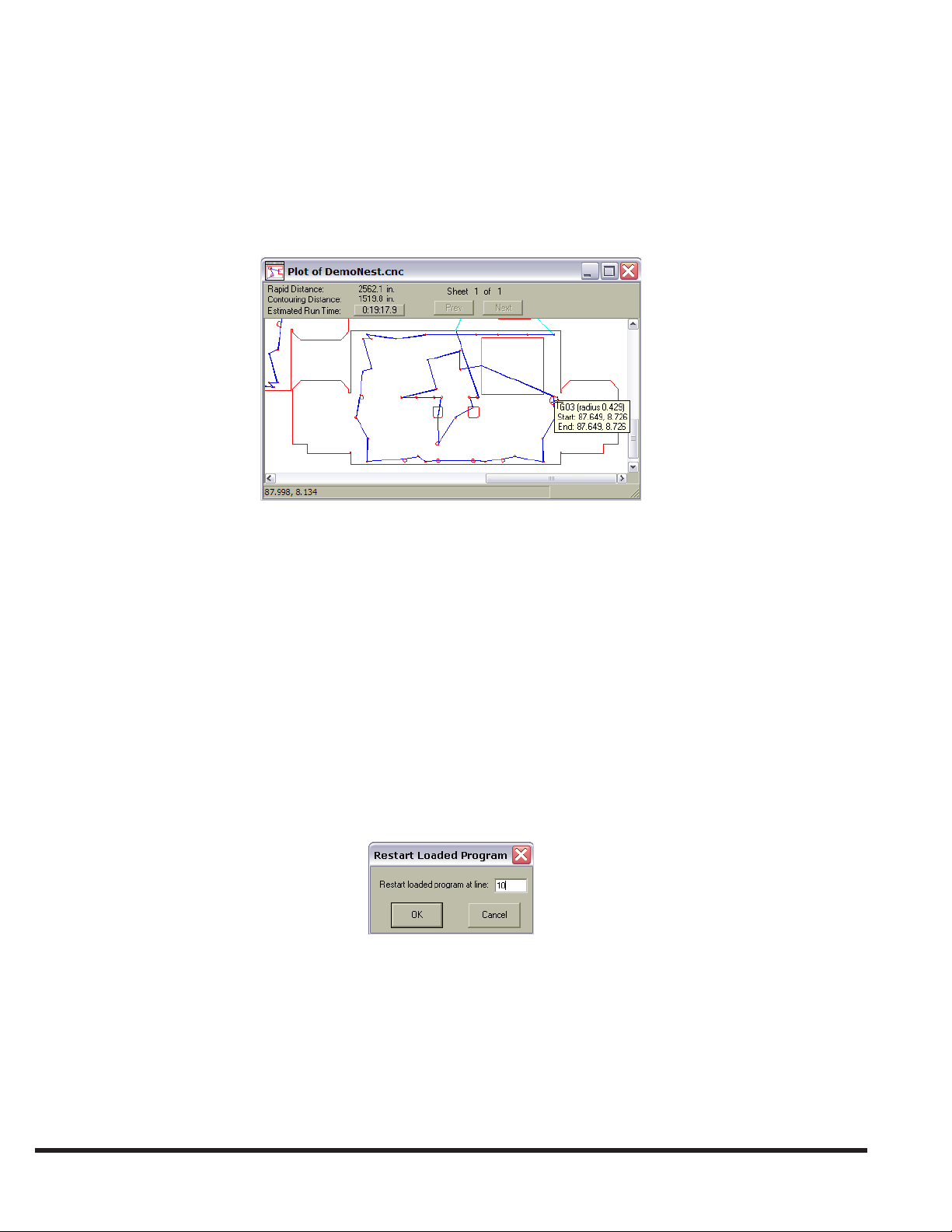
PLOT NC PROGRAMS
When the active window is an NC Program Edit window, the File | Plot NC Program command can be used to display a
graphical plot of the cutting program, one sheet at a time.
If the program has no syntax errors, this command will open a new Program Plot window showing the programmed tool
path. The plot represents where the cutting head would move if the operator ran the program. If the program has a syntax
error, selecting “Plot NC Program” will only display the error message, and the cursor in the Program Edit window will be
positioned on the line containing the error.
The Program Plot window uses different colors to display two types of rapid traverse moves (light blue for Z-axis up and
dark blue for Z-axis down), and two types of contouring moves (red for laser on and green for laser off). When the program
uses more than one sheet, the “Next” and “Prev” buttons change the plot window to display another sheet. The plotting
software interprets M50 in the program as the beginning of another sheet.
The top section of the Program Plot window displays the total Rapid Distance, Contouring Distance, and Estimated Run
Time for each sheet. The estimated run time does not include time to exchange pallets (M50) or the effect of the Feedrate
Override setting. The plotting function assumes that the pallets are in position and the machine is ready to run.
7-19
EM-551 (N-04/11)
Page 30
At the bottom of the Program Plot window, a status bar displays the overall X-axis and Y-axis dimensions of the cutting
program.
To change the plot window magnication, use the Zoom functions (see WINDOW ZOOMING in the VIEW MENU
section).
The Program Plot window can also display information about individual lines and arcs in a program. When the cursor is
positioned on a line or arc, a small pop-up window displays the command type (G00, G01, G02, or G03) with the X and Y
machine coordinates of the start and end. The pop-up window also displays the radius for a G02 or G03 arc.
Keyboard Shortcut: Ctrl + T
RESTART LOADED PROGRAM
File | Restart Loaded Program activates the Program Restart function, which allows a program to be restarted at a
specied line number. This function is intended for use when long programs are terminated before completion and the
normal program recovery method cannot be used. Program Restart is particularly useful with the Automatic Laser Shutdown function (see Auto SHUT-DOWN, in the LASER MENU section), which will display the last absolute line number
executed when a program has not run to completion.
Note: Restart Loaded Program will be enabled only if a program is loaded, the machine is in Auto mode, and is not
currently running a program. At all other times, this menu command will appear grayed, indicating the Program
Restart function is disabled.
When this command is selected, the Restart Loaded Program window will be displayed, prompting the user for an absolute
line number to restart the program at.
Note: Absolute line numbers identify the sequential position of a row or block of code in a program le. This number is
always relative to the rst line in the program, and is not necessarily the same as the optional program line number,
“Nxxxxx”.
The absolute line number of a part program is displayed in the Main Status Bar when the program le is open in a Program
Edit window, and that window is the active window. To determine the absolute line number corresponding to a given block
in a program le, open the le, move the cursor to the desired block and observe the line number in the status bar.
Note: If any window other than a Program Edit window is the active window, the line number will not be displayed in
EM-551 (N-04/11)
7-20
Page 31

the Main Status Bar.
Selecting “Cancel” will close the dialog and abort the restart operation. Selecting “OK” will cause the control to search
through the program from the beginning until it nds the desired line number. A message window will be displayed, stating:
“Please wait while restart line number is found”. This may take a few seconds to nish. If the line number is not reached
before an M30, M02, or M99 in a main program, an error will be displayed stating “Restart End” and the program will be
rewound.
After the line number is reached, the CNC Run Window will be updated to show the next line to be executed. Press “CYCLE
START” and the Z-axis will move to the full up position, then the X- and Y-axes will move from the current position to
the beginning of the current block at 500 IPM. Normal program execution will resume from there. If the program would
normally have been cutting at this point, the Z-axis will move down and cutting will resume, otherwise the head will remain
up until the program commands it down to start cutting.
The following restrictions apply to the Program Restart function:
The • Program Restart function works best with “straight line” programs, for example, programs that do not contain
subroutine calls, macro calls, or “while” loops.
A program cannot be restarted inside a macro.•
A program can be restarted inside a subroutine as long as that subroutine is located in the same le as the main program. •
Note, however, if this is done, the program will restart at the rst instance the subroutine is called.
If a program is restarted inside a “while” loop, the program will restart at the rst iteration through the loop.•
If the work coordinate system of a program depends on the starting position of the cutting head (for example, a program •
beginning with G92 X0 Y0), then the program will not restart at the correct work coordinates unless the cutting head
has not moved since the program was terminated.
Keyboard Shortcut: { Alt, F, E } sequence
File | Print uses the specied printer to print the document displayed in the active window. This command opens the Print
window containing the following controls:
Note: The File | Print command is enabled only when the currently active window contains a document type that supports
printing, such as program and Process Parameter documents.
Use these controls in the Print window to specify how the le is to be printed:
Name: This box displays a list of printers connected to the computer.
7-21
EM-551 (N-04/11)
Page 32

Properties: Select this button to set up options for the selected printer. The options available depend on the features of the
printer specied in the “Name” eld.
Print to le: Check this box to print the document to a le instead of routing it directly to a printer. It will prompt the user
to specify the le name and location.
Print range: This section species what portion of the document to print: the entire document, specic pages, or the
selection highlighted.
Number of copies: This box species how many copies of the document to print.
Collate: When printing more than one copy, this selection species whether the copies will be collated.
Keyboard Shortcut: Ctrl + P or { Alt, F, P } sequence
PRINT PREVIEW
Use File | Print Preview to display the document in the active window, as it will appear when printed.
Note: This command is enabled only when the currently active window contains a document type that supports printing,
such as NC Program and Process Parameter documents.
The Print Preview command opens a Print Preview window in which one or two pages of the active document are
displayed in their printed format. A toolbar at the top of the Print Preview window contains buttons for changing the page
and scaling of the preview:
Print: Open the ‘Print’ dialog box to start a print job.
Next Page: Preview the next printed page.
Prev. Page: Preview the previous printed page.
One Page/Two Page: Toggle between previewing one or two pages at a time.
Zoom In: Take a closer look at the printed page.
Zoom Out: Take a larger look at the printed page.
Close: Return from Print Preview to the editing window.
Keyboard Shortcut: { Alt, F, V } sequence
PRINT SETUP
This File | Print Setup command species where and how to print a document. The Print Setup command opens the Print
Setup window. Use the controls in this dialog box to select a printer and printing options.
EM-551 (N-04/11)
7-22
Page 33

Name: This eld displays a list of printers connected to the computer.
7-23
EM-551 (N-04/11)
Page 34

Properties: Select this button to set up options for the selected printer. The options available depend on the features of the
printer specied in the “Name” eld.
Paper Size: Species the size of paper on which to print the document.
Paper Source: Species where the paper is located in the printer. Different printer models support different paper sources;
such as the upper tray, envelope feed and manual feed.
Orientation: Species whether the document should be printed with its top along the short edge of the paper (portrait) or
along the long edge of the paper (landscape).
Network: Select this button to connect to a network shared printer.
Keyboard Shortcut: { Alt, F, R } sequence
MRU FILE LIST
When closing a Process Parameter le, NC Program le or Batch Program le, that le name is added to the Most Recently
Used (MRU) File List. This list, which is displayed near the bottom of the File menu, can contain up to six le names. To
quickly reopen a le that was recently closed, simply select the corresponding item from the MRU File List.
Keyboard Shortcut: { Alt, F, 1 } , { Alt, F, 2 } , { Alt, F, 3 } or { Alt, F, 4 } sequence
OPEN OPERATOR LOG
The Operator Log File is a text le that the user can use as a simple note pad. It can be quickly opened by using the File
| Open Operator Log command.
EXIT
File | Exit will terminate the CNC/HMI program. Before exiting, always make sure the servo drives are off, laser power
supply is off and any open le changes have been saved. The Exit command is disabled while cutting program execution
is in progress.
Keyboard Shortcut: Alt + F4 or { Alt, F, X } sequence
“X” button on Laser Display window Title Bar:
Double-click icon on Laser Display window Title Bar:
EDIT MENU
Use the Edit menu commands for common text editing functions. These commands are only enabled when an NC Program
window is the currently active window.
EM-551 (N-04/11)
7-24
Page 35

UNDO…
Edit | Undo… will reverse the last editing action, if possible. The name of the command changes depending on the last
action (for example, “Undo Typing”, “Undo Cut”, etc.).
Keyboard Shortcut: Ctrl + Z or Alt + Backspace or { Alt, E, U } sequence
CUT
Edit | Cut will remove the currently selected text from the le and put it on the clipboard. Text in the clipboard can be
pasted to another location. This command is unavailable if no text is currently selected. Cutting text to the clipboard
replaces anything that may have been previously stored on the clipboard.
Keyboard Shortcut: Ctrl + X or { Alt, E, T } sequence
COPY
Edit | Copy will place a copy of the selected text on the clipboard without removing the selection from the active le.
This command is unavailable if no data is currently selected. Copying text to the clipboard replaces any previous clipboard
contents.
Keyboard Shortcut: Ctrl + C or { Alt, E, C } sequence
PASTE
Edit | Paste inserts a copy of the clipboard contents at the insertion point in the active le window. This command is
unavailable if the clipboard is empty.
Keyboard Shortcut: Ctrl + V or { Alt, E, P } sequence
FIND
Edit | Find opens the Find window, allowing the user to specify text to search for in the active le. The Find window
contains check boxes to specify matching the case of the searched letters (uppercase or lowercase), and whole words only.
Use the direction buttons to specify searching “Down” (towards end of le) or “Up” (towards beginning of le). After
entering text to search for in the “Find what” eld, click “Find Next” to nd the rst occurrence of the specied text.
7-25
EM-551 (N-04/11)
Page 36

Note: After “Find Next” has been selected, the Find window will close. The F3 key on the keyboard can now be used as
a “Find Next” shortcut, nding additional instances of the specied text.
Keyboard Shortcut: Ctrl + F or { Alt, E, F } sequence
REPLACE
Edit | Replace will open the Replace window, which functions similar to the Find window, except that when specied
text is found, it can be replaced with another text string specied in the “Replace with” eld. Use the “Replace” button to
replace only the text selection that is currently highlighted. Use “Replace All” to replace all occurrences of the specied
text in the entire le at once.
Keyboard Shortcut: { Alt, E, R } sequence
VIEW MENU
The View menu allows the user to change how the user interface is displayed and congured, and open various status
display windows.
CONTROL BAR
View | Control Bars displays a y-out menu with selections that display or hide the various control bars. A control bar is a
group of user interface buttons and/or indicators that can be displayed or hidden with one command. A check mark appears
next to the menu item for each control bar that is currently displayed.
EM-551 (N-04/11)
7-26
Page 37

Note: At times, changes to the state of a control bar will not be permitted, in which case that menu item will be disabled.
For example, the Process Status Control Bar cannot be displayed when the control is in Jog mode.
Standard Toolbar: The Standard Toolbar contains buttons for common commands, such as “File Open” and “Load Current
Program”. See TOOL BAR in the HMI OVERVIEW section for more details.
Status Bar: The main status bar is at the bottom of the application window. It contains operator help messages, the program
line number, and the time. See MAIN STATUS BAR in the HMI OVERVIEW section for more details.
Process Status Bar: The Process Status Bar displays actual cutting parameters. See PROCESS STATUS BAR in the HMI
OVERVIEW section for more details.
Operator Console: This control bar contains controls for operating mode, override settings, and laser control. See
OPERATOR CONSOLE in the CONTROL BARS section for more details.
Overrides: This submenu item displays or hides the Override Adjust Control Bar, used to change the Assist Gas pressure or
Feedrate override setting. See OVERRIDE ADJUST in the CONTROL BARS section for more details.
Aux.: This submenu item displays or hides the Auxiliary Functions Control Bar, which contains “Assist Gas” and “Fume
Blower” buttons/indicators. See AUXILIARY FUNCTIONS in the CONTROL BARS section for more details.
Fault Indicators: The three “Fault” indicators are displayed as one control bar. If the control bar is moved and then closed,
this command will open the control bar at the default screen location (on the right side of the tool bar). See STATUS
INDICATORS TOOL BAR in the HMI OVERVIEW section for more details.
Apply Default Locations: This submenu command displays all control bars at their default screen locations. Use this
command to restore any control bars that were moved or closed.
Keyboard Shortcut: { Alt, V, B, D } sequence
LANGUAGE
View | Language opens a y-out menu showing the available user interface languages. Use this command to change the
language used for all user interface text display by the Laser System CNC/HMI application. A check mark will appear next
to the currently active language. Before selecting a new language, save/close any open les. The CNC/HMI application
will automatically close after the new language is selected. When the CNC/HMI application is restarted, the new user
interface language will be active.
7-27
EM-551 (N-04/11)
Page 38

Keyboard Shortcut: { Alt, V, L } sequence
UNITS
View | Units opens a y-out menu to congure the user interface for displaying English or Metric units.
When this command is selected, the English/Metric menu appears with a check mark beside the currently selected display
units. This selection does NOT affect program execution in inch mode (G20) or metric mode (G21).
Keyboard Shortcut: { Alt, V, U } sequence
ALARMS AND MESSAGES WINDOW
The Alarms and Messages window displays a list of all currently active alarm and FYI messages. Messages are displayed
in different colors according to the type of message. To further assist in identifying each message condition, a [letter:
number] code precedes the text for each message.
System alarm messages are displayed in • Red, and preceded by a unique [A:nnnn] identier.
FYI messages are displayed in • Blue, and preceded by a unique [M:nnnn] identier.
Laser alarm messages are displayed in• Maroon, and preceded by a unique [L:nnnn] identier.
EM-551 (N-04/11)
7-28
Page 39

The “History” button in the Alarms and Messages window can be used to open an Alarm History window that displays a
list of the 250 most recent alarm and operator messages.
Any system alarm or laser alarm causes machine operation to stop. Conditions that cause alarms must be corrected before
operation can continue. When an alarm condition exists, the “Alarm” indicator on the Status Indicators Control Bar will
be colored red.
Conditions that cause FYI messages do not prevent machine operation but are useful to the operator as a reminder of some
required action or that the machine is in a special mode (Example: Remote Station enabled). When an FYI message is
pending, the “Message” indicator on the Status Indicators Control Bar will be colored yellow.
Status Indicators Control Bar : or
Keyboard Shortcut: { Alt, V, A} sequence
AXES POSITIONS
View | Axes Positions opens the Axes Positions window, which is used to monitor the current position of the cutting head in
Machine or Work coordinates. The displayed positions change when any axis moves. Select either the “Absolute Machine”
or “Work” button to specify the type of displayed coordinates. The display eld above the coordinates also describes the
selection.
7-29
EM-551 (N-04/11)
Page 40

When the Machine Offsets window species non-zero Offset Distances for the alternate machine coordinate system, the
Axes Positions window has another button to select those coordinates:
When the Axes Positions window displays a button for the Alternate Machine Coordinate System, the window also
indicates the G code of the active machine coordinate system at the bottom (G150 standard or G153 alternate).
Toolbar Shortcut:
Keyboard Shortcut: { Alt, V, X } sequence
MODAL G CODES
View | Modal G Codes opens the Modal G Codes window. This window displays the active G code from each modal group
while a program is running. The software updates the window every 200 milliseconds.
Keyboard Shortcut: { Alt, V, M } sequence
ALL POSITION INFORMATION
View | All Position Information opens the All Positions window, which displays the position of the cutting nozzle in
Machine and Work coordinates at the same time. The displayed positions change when any axis moves. This window also
displays the “Distance to Go” and “Following Error” of the current motion command, the combined X-axis and Y-axis
Feedrate, and the target and actual nozzle standoff.
EM-551 (N-04/11)
7-30
Page 41

Note: When the Z-axis raises the nozzle greater than 0.040 inches (1 mm) above the target standoff position, the actual
standoff display reads “–”.
When the Machine Offsets window species non-zero Offset Distances for the alternate machine coordinate system, the All
Positions window includes the cutting head position in the alternate machine coordinate system.
Keyboard Shortcut: { Alt, V, P } sequence
RUN WINDOW GRAPHICS
The View | Run Window Graphics command enables or disables the graphic display of the loaded sheet program plot in
the CNC Run Window. When the function is active, a check mark will be displayed next to “Run Window Graphics” in the
View menu, and the CNC Run Window will display the plot graphics.
Keyboard Shortcut: { Alt, V, G } sequence
WINDOW ZOOMING
The Zoom commands at the bottom of the View menu can be used to change the displayed area of an NC Program Plot
window or the Run Window Graphics plot.
Zoom Window: Use this command to select a rectangular area to magnify. The Zoom Window command changes the
cursor appearance to that of the ‘Zoom Area’ selection cursor: Drag this cursor to draw a rectangular outline around
the area of interest. After the mouse button has been released to complete the drag, the outlined rectangle will ll the
plot window.
Zoom Extents: Used in the CNC Run Window to scale the plot area to match the machine pallet size. In a Program Plot
window, this command will scale the display so that the cutting program completely lls the plot window. This is the
default display mode for both the CNC Run Window and Program Plot window.
7-31
EM-551 (N-04/11)
Page 42

Zoom Parts: Used in the CNC Run Window to scale the plot area so that it is completely lled by the cutting program
parts.
Zoom In: Zooming-in magnies the center portion of the plot by one zoom increment.
Zoom Out: Zooming-out displays a larger area than the previous plot. This makes the displayed program plot one zoom
increment smaller.
Keyboard Shortcut: Ctrl + Home = Zoom Extents
Ctrl + Page Up = Zoom In
Ctrl + Page Down = Zoom Out
Pointing Device : Clicking the right button in a plot window will display a pop-up menu containing the
Zoom commands.
Pointing Device : When the cursor is positioned in a plot window, rotating the mouse wheel will activate
the Zoom-in or Zoom-out function.
MAINTENANCE MENU
Use the Maintenance (Maint.) menu for access to various machine maintenance and diagnostic functions.
CONFIGURATION
Maint. | Conguration opens the Machine Conguration window, which is used to view and modify system parameters
and installed option settings. The Machine Conguration window is actually several dialogs, or pages, housed in a common
frame window. Along the top of the frame window is a row of tabs, one for each conguration page. Select any tab to open
the corresponding page and close the previously open page.
Note: The Machine Conguration command is disabled while the laser control is in Auto mode.
The Machine Conguration window is divided into these sections; one window page covers each section:
General Conguration•
Option Conguration•
X Axis Conguration•
Y Axis Conguration•
Z-axis Conguration•
Auxiliary Conguration•
I/O Labels Conguration•
Serial Port Conguration•
Note: The ‘Machine Conguration’ dialog is for use primarily by CINCINNATI Service personnel to modify system
parameters not normally changed by the operator. Changing conguration parameters by non-CINCINNATI
EM-551 (N-04/11)
7-32
Page 43

personnel is restricted to the parameters specied in the “Edit” button function description.
Button Functions
OK: Closes Machine Conguration window. Any changes will be saved.
Cancel: Closes Machine Conguration window without saving changes.
Edit: When the Machine Conguration window is rst opened, all parameter editing is disabled. Selecting this button will
enable editing if the edit access requirements listed are met.
Administrator: All values on all pages can be edited.
Manager: All values except those on the Options page can be edited.
Operator: Only a few parameters can be edited by operators. See the individual conguration page
descriptions.
Keyboard Shortcut: { Alt, M, C } sequence
General Conguration
The General Conguration tab is used for viewing and modifying general machine conguration parameters. This page is
always the rst page displayed when the Machine Conguration window is opened.
Pallet Conguration: Species pallet size (and gantry travel). Choices are 4’ x 8’, 5’ x 10’, 6’ x 12’, 2m x 4m or 8’ x 20’.
Resonator Capacity: Species the nominal maximum power available from the laser resonator.
X Y Axis Jog Speed: The target speed when the Front Panel or Remote Station pushbuttons are used to jog the X-axis or
Y-axis.
X Y Rapid Jog Speed: Species the jog speed for both the X and Y-axes when the “RAPID TRAVERSE” button on the
Front Panel is selected. This value must be greater than or equal to X/Y-axis Jog Speed.
X Y Jog/Rapid Acc/Dec: This parameter species the acceleration / deceleration rate for X and Y-axis moves in Jog mode
and during rapid (G00) moves.
7-33
EM-551 (N-04/11)
Page 44

X Y Contouring Acc/Dec: This parameter species the acceleration / deceleration rate for X and Y-axis contouring moves
(G1, G2, or G3).
Max. Cutting Jerk: Species maximum servo “Jerk” value used during contouring.
Rapids (G00) Jerk: Species the servo “Jerk” value used during rapid (G00) moves.
Smart Rapids Jerk: Species the servo “Jerk” value used during Smart Rapids moves.
DPC DAC Offset: To command pulse duty cycle, the Laser System control sends a signal to the laser control. This factory-
set parameter calibrates that signal to produce 100% duty cycle.
Update PLCs: The “Update PLCs” button starts the process of reloading PLC software in the PMAC motion controller.
This process forces the CNC/HMI application to be shut down and restarted.
Process Library Feedrate
Set Global Variable: Enables or disables the use of cutting speed in Process Parameter les. When checked, the contouring
feedrate can be specied along with the other cutting parameters in Process Parameter windows. If not checked, the
Feedrate parameter will not be visible in Process Parameter windows.
Variable No.: Species the number of the global variable used for the Process Parameter contouring feedrate. Valid variable
numbers are from 100 to 999. If Set Global Variable is checked, the cutting speed specied in the Process Parameter
le will be written to the global variable when the program commands a “G89 P__” block. The “Variable No.” eld is
visible only if “Set Global Variable” is checked.
Note: This parameter can be edited by the Operator.
Start of Program Initialization
The Start of Program Initialization feature is intended to eliminate any inconsistencies that might occur on the rst cut
sequence following a long interruption in cutting. In the event that a cutting sequence has not occurred for a dened amount
of time, the control will delay the next cut sequence briey, allowing enough “initialization time” for the laser beam to
stabilize, and to purge the assist gas and air blast lines. The cut sequence will then proceed as normal
Beam Off Time: The length of time for which the laser beam must be turned off between cuts to activate the Start of
Program Initialization function. A value of zero disables Start of Program Initialization.
Note: This parameter can be edited by the Operator.
Extended pierce dwell: The amount of time by which the rst pierce cycle time is automatically increased when the
Extended Pierce Cycle function is activated. If no pierce cycle is programmed, a dwell of Extra Cycle Time seconds is
executed after the beam turns on, before motion begins.
Note: This parameter can be edited by the Operator.
Assist gas purge: If the beam has been off for a period of time greater than Beam Off Time, the assist gas line will be purged
for Assist gas purge time, before the next pierce is started.
Note: This parameter can be edited by the Operator.
Rapid pierce airblast: If the beam has been off for a period of time greater than Beam Off Time, an additional amount of
time specied by Rapid pierce airblast will be added to the airblast duration of the next Rapid Pierce cycle.
Note: This parameter can be edited by the Operator.
Motion Controller Lookahead
The PMAC motion controller can perform sophisticated lookahead calculations on programmed trajectories to ensure
that the trajectories do not violate specied maximum quantities for the axes involved in the moves. Some laser system
EM-551 (N-04/11)
7-34
Page 45

applications may require that lookahead be enabled.
Enable: Motion controller lookahead is enabled only if this box is checked.
Number of lookahead segments: Species how far the motion contoller looks ahead (each move command is split into
many small segments), when the lookahead function is active. This setting is only visible if the Motion Controller
Lookahead Enable box is checked.
Automatic Laser Shut-down
See the Auto Shut-down topic for a complete description of the Automatic Laser Shut-down feature.
Auto Shut-down time: If program execution is suspended or inactive for at least this long while automatic laser shut-down
is armed, the laser shut-down sequence will be initiated.
Automatically arm Auto Shut-down: When this box is checked, automatic laser shut-down will automatically be armed
each time program execution is started. This makes it unnecessary to use the Auto Shut-down command from the Laser
menu after starting a program to arm auto shut-down.
Jumper-Selectable Conguration
Gated cutting area enclosed: Indicates this machine is equipped with a gated cutting area enclosure safety system.
External proximity safety device (no enclosure): Indicates this machine uses an external proximity safety system, such as
an area scanner or safety mats, instead of a cutting area enclosure.
Option Conguration
The Options tab contains check boxes to enable or disable various optional machine functions. An option is enabled if the
corresponding box is checked.
Change Options: This button is only visible to the Administrator user, and prompts for the entry of an access code. The
proper access code must be given before any machine options can be changed.
Note: The “Edit” button will not be displayed until the “Change Options” button has been selected.
7-35
EM-551 (N-04/11)
Page 46

Note: The Data Logging and Service options do not require an access code, and be changed by the Manager user.
Ball Transfer: This option indicates that the Laser System is equipped with optional ball transfer mechanism used to assist
in moving material sheets on the pallets.
CNC Serial Output: This option enables the “DPRNT” option, conguring the control to output character strings to a
remote computer via an additional serial port.
Opposite Hand: This option congures control software for opposite hand operation (the Operator Control Station is on the
opposite side of the machine frame from the standard location).
Lower Pallet Special Function: This option allows laser cutting with a workpiece, such as rectangular tubing, on the lower
pallet even though the top surface of the workpiece extends several inches above the pallet. Standard distance is 24
inches. Full travel for y may be implemented.
Workpiece Edge Detection: This option can be used to automatically shift and rotate the work coordinate system, effectively
aligning the program with the workpiece.
Rapid Pierce: This option can be used to reduce piercing times for thick mild steel.
Load Frame Safety Mats: This option is a safety feature that disables the laser system if there is not enough weight applied
to the safety mats, which are installed on the oor around the laser near the operator control.
Micro Weld Part Tabbing: This option can be used in conjunction with the Modular Material Handling System automation
to prevent parts cut from thick material from dropping out of the sheet during transport.
Motion Control Toolbar: The optional motion control toolbar contains GUI buttons that allow axis jogging and cycle start/
stop and reset commands to be initiated from the laser system display window as well as the control station front panel
buttons. This control bar can be used for remote diagnostic purposes.
Process Monitor: This option enables the optional Process Monitor System, which uses measurements of light intensity
and plasma conductance to improve cutting performance.
Data Logging Options
Fault Logging: Enables automatic logging of system alarms and laser alarms to the text le “FAULT.LOG” in folder “\\
Cnclsr32\”.
Machine Logging: Enables automatic logging of various statistical and conguration data to the text le “MACHINE.
LOG” in folder “\\Cnclsr32\”.
Production Logging: Enables automatic logging of program execution history data to the text le “PRODUCT.LOG” in
folder “\\Cnclsr32\”.
XML Log File: Enables automatic daily recording of all Fault, Machine, and Product log data to one le in “.xml” format.
The le name indicates the date: “yyyymmdd.XML”; where “yyyy” is the year, “mm” is the month (01 to 12) and “dd”
is the date (01 to 31). The daily “.xml” les are in folder “\\Cnclsr32\Logs\”. This must be enabled if the remote web
dashboard is used on computers on the same network. See remote message interface.
Service Options
PMAC Debug Mode: Enables the display of diagnostic information output by the PMAC servo controller to the PMAC
Interface Console window. This is used only by CINCINNATI INCORPORATED personnel for diagnostic purposes.
Remote Message Interface: This setting congures the Laser System software to communicate with other software provided
by the user. The software applications can exchange messages regarding which program to run, machine status, etc. For
a detailed description, contact CINCINNATI Laser Service.
EM-551 (N-04/11)
7-36
Page 47

Automation System Options
Automation System: This setting congures the Laser System software to interface with optional pallet loading equipment.
The Options page (in Edit mode) displays the Automation System options in a pull-down menu. For a detailed description
of the Automation system options, contact CINCINNATI Laser Service.
Cameras
Species IP address conguration for up to two cameras used to monitor the cutting area.
X and Y Axis Conguration
The X Axis Conguration and Y Axis Conguration tabs are used to view and modify parameters pertaining to the X-axis and
Y-axis servo systems. Two nearly identical pages are provided, one for X-axis parameters and one for Y-axis parameters.
Home Offset: Species the distance from Home reference mark where the axis will come to rest after completing the Axes
Home operation.
DAC Output Offsets: The DC offsets of the motion controller command signals. These values are set during the initial setup
and calibration of the servo system.
Soft Overtravel Limits: Species the positions, in machine coordinates, beyond which controlled axis motion is not allowed.
If an axis reaches a position less than the negative overtravel limit or greater than the positive overtravel limit, axis
motion in the same direction is disabled and an alarm is reported.
Rapid (G00) Speed: The desired (maximum) speed to be achieved during rapid (G00) moves.
Following Error Limit: The maximum magnitude the servo following error can attain before the “Fatal following error”
alarm is reported.
Jog Speed Clamp Zone Dist.: The jog speed clamp zone is an area inside the perimeter of the X-axis and Y-axis travel
limits. This parameter species the distance from the start of the clamp zone to the nominal travel limit for each axis.
When jogging toward the travel limit in this zone, the jog feedrate is automatically limited to the Jog Speed in Clamp
Zone parameter. Outside this zone, the jog speed shown in the General Machine Conguration tab is used.
Jog Speed in Clamp Zone: The speed to which the axis is automatically limited when jogging toward the travel limit while
inside the rapid clamp zone. This value must be less than or equal to X/Y-axis Jog Speed on the General Machine
Conguration tab.
Y-Travel Limit for Lower Pallet Special Function Mode (M43): (Y-axis page only) When using the Lower Pallet Special
Function, the Y-axis travel range is limited for safety purposes. Whenever M43 is active, this value replaces the +Y
7-37
EM-551 (N-04/11)
Page 48

Soft Overtravel Limit as the positive Y-axis travel limit. Standard distance is 24 inches. Full travel for y may be
implemented.
Z Axis Conguration
The Z Axis Conguration page is used for viewing and modifying parameters pertaining to the Z-axis servo system.
Home Offset: Species the Distance from Home reference mark where the axis will come to rest after completing the Axes
Home operation.
DAC Offset: The DC offset of the Z-axis D/A converter / amplier. This value is set during the initial setup and calibration
of the Z-axis servo system.
Soft Overtravel Limits: Species the positions, in machine coordinates, beyond which controlled axis motion is not allowed.
If the Z-axis reaches a position less than the negative overtravel limit or greater than the positive overtravel limit, axis
motion in the same direction is disabled and an alarm is reported.
Top of Pallet Positions: Species the positions, in absolute Z-axis coordinates, corresponding to the top of the upper and
lower pallets when material supports are new.
Height Sensing Unit: The height sensing system installed on the machine. The two choices in the menu are PLHSU nnnn
HSU and Cincinnati Auto-cal HSS. All CL-900’s are shipped with Cincinnati Auto-cal HSS.
Z-axis Jog Speed: The target speed when the “Front Panel” or “Remote Station” pushbuttons are used to jog the Z-axis.
Following Error Limit: The maximum magnitude the Z-axis servo following error can attain before the “Fatal following
error” alarm is reported.
Max Speed for all Moves: The target speed for all programmed Z-axis moves.
Contact Head Acc/Dec: The rate of acceleration and deceleration for all Z-axis moves when the contact cutting head is
used.
Noncontact Head Acc/Dec: The rate of acceleration and deceleration for all Z-axis moves when the noncontact cutting
head is used.
Tip Touch Warning Delay: When a brief noncontact tip touch condition occurs, the software will display this warning
message:
EM-551 (N-04/11)
7-38
Page 49

If the tip touch condition clears before the Tip Touch Warning Delay expires, the software will not stop the program.
If the tip touch condition lasts longer than the Warning Delay, then a “Noncontact Z-tip touch” system alarm will be
reported and program execution will be terminated.
Auxiliary Conguration
The Auxiliary Conguration tab is used for viewing and modifying conguration parameters for auxiliary functions and
subsystems.
Pallet controller: This parameter congures the Laser System control to interface with the specied type of pallet drive.
Pallet slow speed time-out: When the pallet enters the slow speed phase, the control allows the pallet this much time to
reach position, before it reports the “Pallet motion timed out” alarm.
Pallet motion warning delay: Some Laser Systems use a signal (a horn or light) to warn operators before moving the
pallets. This parameter determines how long the software activates the warning signal before it moves the pallets. The
control software starts the warning signal when the program or the operator requests pallet motion. The warning signal
continues until pallet motion stops.
Pallet wind-up timer: After receiving the signal that a pallet reached the commanded position, the pallet drive continues
to pull on the pallet for a short time, applying tension to hold the pallet against the stop. The conguration parameter
species this “wind-up” time.
Chiller fault time: A Chiller Fault condition occurs when the laser control software activates the output to start the chiller
but does not receive a return signal conrming that the chiller started. This parameter determines how long the software
waits between recognizing the Chiller Fault condition and activating the Chiller Fault system alarm. If the chiller starts
7-39
EM-551 (N-04/11)
Page 50

during that time, the software does not activate the alarm. The time delay is a conguration parameter because different
chiller models may require different starting times.
Auxiliary output (M151) time-out: When an M151 code is commanded in an NC Program, program execution pauses
and waits for the corresponding M151 customer input to turn on. This parameter species the maximum time that the
control will wait for the M151 customer input, at which point an M151 alarm will be triggered.
Ball Transfer Down OFF Delay: Species additional motor rotation time after the ball transfer down switch has been
tripped. This value is used to ne-tune the nal stopping position of the ball transfer, and ensure that the lower pallet
can pass over the mechanism.
Ball Transfer Inch Mode: Species a special “manual adjustment” mode for maintenance purposes. When this button is
depressed, the ball transfer will decelerate to a stop whenever the remote pendant buttons are released. Normal operation
dictates that the ball transfer move all the way up / down with any momentary button press. This mode allows for
manual adjustment of the proximity switches, without risk of overtravel.
Assist Gas System
Valve Max Rating: The range of the assist gas pressure valve, for example, the pressure output expected when the maximum
command signal is input to the valve.
DAC Offset: The assist gas pressure controller receives a voltage signal from the Laser System control. This parameter
adjusts the signal for a commanded pressure. The gas pressure calibration procedure sets this parameter.
Note: The two parameters above each have a Low and High setting. The High settings apply to the higher pressure rated
valve, which is used for Nitrogen assist gas. The Low settings apply to the lower pressure rated, higher accuracy
valve used for Oxygen and Air assist gas.
Max Settling Time: When the program changes the commanded assist gas pressure, the control allows the assist gas system
this much time to respond before it reports an “Assist gas valve failed to maintain target pressure” alarm.
Auto Focus Head
See the AUTO FOCUS CUTTING HEAD section for Auto Focus Head conguration parameter descriptions.
Fume Collection System
Blower OFF delay: When a program ends, the fume blower remains on for the time specied by this parameter.
The Auxiliary page displays the next three parameters only when Pallet Conguration on the General Conguration page
is 8’ x 20’. The 8’ x 20’ cutting area uses a fume collection system with multiple exhaust sections controlled with separate
damper gates. The software only opens the gates for exhaust sections near the cutting head position.
Active Doors: This parameter species the number of fume exhaust section gates that the software will keep open at
the same time.
Zone On Delay: If the cutting head moves into the area of a closed exhaust section for this length of time, then the
software opens the gate for that section.
Zone Off Delay: If the cutting head moves outside the area of an open exhaust section for this length of time, then the
software closes the gate for that section.
I/O Labels Conguration
The I/O Labels Conguration tab is used for viewing and modifying the machine I/O description labels. Both input and
output labels are displayed for all machine I/O boards. These I/O labels are displayed in the I/O Monitor windows when
a specic I/O state edit control is selected, and in the I/O Watch Window when the selection dialog is used to congure
a specic watch point. The I/O Labels Conguration tab can be used to add or change description labels for custom I/O
connections.
EM-551 (N-04/11)
7-40
Page 51

DIAGNOSTICS
Several diagnostic windows are accessible via the Diagnostics y-out submenu, which appears when the Maint | Diagnostics
command is selected.
Input / Output Monitor Windows
The I/O Monitor windows are used to view the states of any discrete inputs or outputs used by the Laser System. The
monitor windows are activated from the Maint | Diagnostics submenu by selecting the desired menu item or by using the
indicated shortcut keys (underlined characters in the submenu). More than one I/O Monitor window can be open at the
same time. I/O Monitor windows are read-only windows; none of the displayed information can be modied by the user
with the trackball or keyboard.
7-41
EM-551 (N-04/11)
Page 52

Each I/O Monitor window contains color-coded state indicators, one for each input or output of the corresponding Macro
Station or Console I/O board. The state indicators are arranged in rows of 8; the terminal number is displayed inside each
‘State Indicator’ text box. If the corresponding input or output is on, the state indicator is colored green with a white
terminal number. Otherwise, the state indicator is colored yellow with a black terminal number. Once open, Macro Station
or I/O Monitor windows are automatically updated to reect any changes in the displayed input or output states.
Keyboard Shortcut: { Alt, M, D, 1 } , { Alt, M, D, 2 } … { Alt, M, D, 8 } sequence
Input / Output Labels
A brief description for each input or output point can be viewed from the I/O Monitor windows by selecting an “I/O state”
indicator, which will cause a small window to open just below the cursor.
The window text is the label of the corresponding input or output. The selected state indicator will be surrounded by an
orange highlight, indicating that the label corresponds to that terminal. Selecting outside the state indicator will close the
label window.
Analog Inputs / Outputs
The Analog I/O window is a diagnostic tool for monitoring the values of all control system analog inputs and outputs. Once
this window is opened, the displayed values are continuously updated. This window is for monitoring purposes only. None
of the displayed values can be changed from the window.
Keyboard Shortcut: { Alt, M, D, A } sequence
EM-551 (N-04/11)
7-42
Page 53

Axis Limit Switch Inputs
The Axis Limit Switch Inputs window uses 24 color-coded state indicators to display the states of 3 limit switches for
each of the 8 motion controller servo axes. There is an indicator for the positive limit switch, negative limit switch and
home limit switch for all 8 axes. If a limit switch is tripped, its indicator will display “on”, using white text on a green
background. Otherwise, the indicator will display “off” in black text on a white background. Once open, this window is
automatically updated to reect any changes in the axis limit switch states.
A label eld is provided to give a logical description of how each axis is currently used. Each label eld is a text box, which
users logged-in as “Administrator” can edit by selecting the “Edit Labels” button.
Keyboard Shortcut: { Alt, M, D, L } sequence
I / O Watch Window
The I/O Watch Window allows any 10 user-selectable I/O points to be monitored together in the same window. The I/O
Watch Window contains 10 read-only text boxes, which, similar to the I/O Monitor Windows, are used as color-coded state
indicators. The text boxes display the board number, terminal number and a brief description of the corresponding I/O
point. If the indicated input or output is on, the state indicator is colored green with white text. Otherwise, the state indicator
is colored yellow with black text. Once open, the I/O Watch Window is automatically updated to reect any changes in the
displayed input or output states.
Initially, all text boxes are blank. Use the “Change” and “Remove” buttons to congure the Watch window. Select an I/O
point for monitoring as follows:
Using the touchscreen or trackball button, select the text box to be used as the state indicator. The selected box will be 1.
highlighted with an orange outline to indicate the selection.
Select the “Change” button. This will open a small window containing a scrolling list of description labels for all 2.
discrete inputs and outputs. This dialog box will contain two buttons: “Select” and “Cancel”.
Scroll the I/O label list to nd the label of the input or output point to be monitored. Select the I/O label (the selection 3.
is highlighted with blue background).
7-43
EM-551 (N-04/11)
Page 54

Click the “Select” button to add the I/O point to the 4. I/O Watch Window. Click “Cancel” to abort the selection. Either
“Select” or “Cancel” will close the dialog box.
To stop monitoring an I/O point in the I/O Watch Window, rst select the text box of the I/O point, and then select the
“Remove” button. The selected state indicator text box will be cleared.
Keyboard Shortcut: { Alt, M, D, W } sequence
Alarm Tracking
Use the Alarm Tracking window to congure the Alarm Tracking diagnostic function. Alarm Tracking allows diagnostic
information to be automatically captured and saved to a disk le after a selected system alarm occurs.
To enable alarm tracking, select any number of system alarms to trigger diagnostic data recording, make sure the Alarm
‘Tracking Enabled’ box is checked, and then select “OK”. If one of the selected system alarms occurs, a short diagnostic
le will be written to the hard disk. The name of this le will be unique so that old data is not overwritten. The “Write Log
File Now” button causes the diagnostic le to be written immediately without waiting for a system alarm. This button is
disabled if Alarm Tracking is not enabled.
Note: Alarm Tracking is a troubleshooting aid. While it is enabled, large numbers of les will be written to the hard drive.
Do not leave Alarm Tracking enabled on a permanent basis during normal operation.
Keyboard Shortcut: { Alt, M, D, T } sequence
Keyboard Shortcut: { Alt, M, D, R, D } sequence
Pallet Gate Control
The Pallet Gate Control window is used to specify the location of the Pallet Gate: “Gate Up” or “Gate Down”. This is used
for maintenance and diagnostic use. The Pallet Gate can not be manually operated when Laser Ready is ON, or when the
control is in Auto or Homing mode.
EM-551 (N-04/11)
7-44
Page 55

STATISTICS
The Maint. | Statistics command opens the Machine Statistics window. Use this window to view statistical information
pertaining to the Laser System. All data values are initially read-only. However, most values can be changed (for resetting
purposes) by Administrator and Manager users.
Control ON time: Total accumulated run time for the Laser System CNC/HMI Software program (hours : minutes :
seconds).
Program Run time: Program execution time. This counter begins when “CYCLE START” is pressed, and stops when
program execution is terminated by “CYCLE STOP”, M30, system alarm, etc.
Beam ON time: The cumulative time the laser beam has been energized (hours : minutes : seconds). This value includes the
time when the beam was on during warm-up/calibration, lens centering, and manual laser power control operations.
Program Cut time: The cumulative time the laser beam has been on while executing a program (hours : minutes : seconds).
Warm-up/calibration, lens centering, etc. times are not included.
Time Elapsed Since Lube: Elapsed time since the X-axis and Y-axis linear bearings were lubricated. Change this value to
zero after manually lubricating the bearings. This time value only increases while a program is executing.
X / Y-axis Travel Since Lube: The linear distance each axis has traveled since the bearings were lubricated. Change these
values to zero after manually lubricating the bearings.
Number of Pallet Exchanges: The number of times either of the following has occurred (in Auto or Jog mode):
The upper pallet moved to the cut position AND the lower pallet moved to the load position.•
The upper pallet moved to the load position AND the lower pallet moved to the cut position.•
7-45
EM-551 (N-04/11)
Page 56

X / Y-axis Travel: The cumulative linear distance each axis has traveled.
Local Disk Capacity: The total storage capacity of the Laser host PC hard disk drive.
Local Disk Free Space: The number of free bytes on the Laser host PC hard disk drive.
Last NC Program Name: The name of the last cutting program loaded for execution.
Last NC Program Cycle Time: Time required to execute the last program. This time measurement starts when “CYCLE
START” is pressed and ends when M30 or M02 is executed in the program.
Button Operation
Edit: This button allows specic users to reset counter values. Administrator and Manager users can edit all statistics
settings except Last NC Program, and Local Disk Usage.
Close: This button closes the Machine Statistics window. If any values have changed, a message box will open, asking
if the changes should be saved (user response: “Yes”, “No” or “Cancel”). Select “Yes” to save the changes or “No” to
discard the changes. Selecting “Cancel” aborts the Close operation.
Refresh: Selecting this button will cause the most recent statistics to be collected and displayed.
Note: The control does not automatically update any of the displayed statistics after the window is opened. The user must
select the “Refresh” button or close/re-open the dialog box to see the current statistics.
Keyboard Shortcut: { Ctrl + A} or { Alt, M, S} sequence
LASER MENU
Use the Laser menu for access to laser-related status information and functions.
LASER STATUS MONITOR
Laser | Status opens the Laser Status Monitor window, which displays real-time laser status information. The information
in this window is for viewing only. Laser parameters cannot be edited from the Laser Status Monitor window. Refer to IPG
documentation for information on specic status items.
EM-551 (N-04/11)
7-46
Page 57

AUTO SHUT-DOWN
Using the Automatic Shut-down function, the Laser System can be programmed to automatically enter an idle state
when the currently active cutting program terminates. In this state, the machine’s servo drives are off (inhibited) and the
main power supply is off, but the control will remain active; The Laser System is now ready for an extended period of
inactivity.
CINCINNATI INCORPORATED does not
recommend completely unattended operation
of a laser cutting system. Although the operator
need not be present while the laser runs in
“UNATTENDED” mode, some qualied personnel
(maintenance, security, etc.) must be available to
deal with emergency situations.
Arming the Automatic Laser Shut-down Function
To arm the Automatic Laser Shut-down function, select the Auto Shut-down command from the Laser menu. When the
Automatic Laser Shut-down function is armed, a check mark will appear next to the menu command.
Note: The Auto Shut-down command is only enabled while program execution is in progress. When the Laser System
is not executing a cutting program, the command will appear grayed, indicating the Automatic Laser Shut-down
function is disabled.
Automatic Shut-down Initiation
Once the automatic laser shut-down function is armed, normal operation resumes until the active cutting program terminates.
Program termination for any of the following reasons will trigger automatic shut-down:
Normal program completion, i.e. • M30, M02, M00 or M01 was encountered, presumably at the end of the program.
Premature program termination caused by any system alarm or fault condition.•
Premature program termination caused by operator intervention such as pressing the CYCLE STOP or EMERGENCY •
STOP button.
If program execution is suspended for longer than the time specied by the Auto Shut-down time setting in the General •
Machine Conguration window (example: M50/Switch Pallets code is encountered and the Pallets NOT READY
pushbutton is never pressed), the program will automatically terminate. In this case, behavior will be similar to normal
program termination; no system alarms will be generated.
The automatic laser shut-down sequence begins immediately after the active program terminates.
Automatic Shut-down Sequence
Whenever an active program is terminated while the Automatic Laser Shut-down function is armed, the control will
execute an automatic shut-down sequence, performing the following tasks in the order listed:
The 1. Shut-down Notication window will pop up, notifying that automatic shut-down will occur at the indicated time.
This message will be displayed for ve minutes, during which time the user can abort the automatic shut-down if
desired. Selecting “Cancel” during this ve minute period will disarm the Automatic Laser Shut-down function and
the control will resume normal operation.
7-47
EM-551 (N-04/11)
Page 58

If the shut-down is not aborted within ve minutes, the servo drives, Laser Ready, and main power supply will be 2.
turned off.
The message displayed in the 3. Shut-down Notication window will change, notifying that shutdown was completed and
the time of actual shutdown (see examples). At this time, the notication window will also display:
The name of the program running when Automatic Shut-down occurred.•
The completion status of the last program: “completed successfully” or “terminated before completion”.•
If the program completion status is “terminated before completion”, a list of all system and laser alarms present •
at the time of program termination will be displayed. The absolute line number identifying which program block
was active when termination occurred will also be displayed. This line number can later be used with the Program
Restart function to restart the program at a specied line.
Note: Absolute line number identies the sequential position of a row or block of code in a program le. This number is
always relative to the rst line in the program and is not necessarily the same as the optional program line number
“Nxxxxx”. When an NC Program Window is the active window, the absolute line number of the line containing the
cursor is displayed in the Main Status Bar.
Keyboard Shortcut: { Alt, L, H} sequence
LASER DIAGNOSTICS
This window is to assist with IPG laser diagnostics. The window contains read-only status information. Refer to the IPG
ber laser documentation for a description of the information displayed here.
EM-551 (N-04/11)
7-48
Page 59

VARIABLES MENU
The Variables menu commands provide access to windows that display variables and offset information used by NC
cutting programs.
LOCAL/GLOBAL VARIABLES
Variables | Local/Global allows the user to view and edit the local (#1 to #99) and global (#100 to #999) variables. All
variables can be edited.
Editing variables while a program is running
can cause improper execution and is strongly
discouraged.
Keyboard Shortcut: { Alt, A, L} sequence
USER I/O VARIABLES
Variables | User I/O displays user I/O variables. The user I/O variables cannot be edited; they can only be changed through
program execution.
Keyboard Shortcut: { Alt, A, U} sequence
7-49
EM-551 (N-04/11)
Page 60

WORK OFFSETS
Variables | Work Offsets allows the user to view or edit the offsets for work coordinate systems 1 through 6 (G54 to
G59) and the External Work Offsets. The user can edit work coordinate offsets only when a program is not executing. (See
G54…G59 Work Coordinate System Selection in the LASER NC PROGRAMMING topic.)
Keyboard Shortcut: { Alt, A, W} sequence
MACHINE OFFSETS
Variables | Work Offsets allows the user to view or edit the offsets for the alternate machine coordinate system. The user
can edit machine coordinate offsets only when a program is not executing.
Offset Distance: These settings specify the distance from the Axes Home position to the X0 or Y0 position in the alternate
machine coordinate system.
Direction: The ‘Reverse’ check box species if the direction of the alternate machine coordinate system axis is opposite
the standard machine axis direction. When the X or Y Offset Distance is not zero, the Axes Positions window and the
All Positions window include the nozzle position in the alternate machine coordinate system.
Keyboard Shortcut: { Alt, A, M} sequence
UTILITIES MENU
Operators can use the Utilities menu to access setup and calibration functions that are performed on a regular basis.
EM-551 (N-04/11)
7-50
Page 61

STANDOFF CALIBRATION
Utilities | Standoff Calibration opens the Standoff Calibration window and puts the Laser System in Standoff Calibration
mode. This is a “Special Operating Mode”, used to check or calibrate the noncontact head height sensing system.
Periodic use of the automated Standoff Calibration function will ensure an accurate standoff between the nozzle tip
and the workpiece. When the “CYCLE START” button is pressed, the cutting head moves down until the nozzle tip
touches the workpiece and then retracts to the desired standoff using the Z-axis motor encoder. This provides an accurate
and repeatable method for independently verifying the standoff accuracy of the capacitive or “Noncontact” sensor. See
NOZZLE STANDOFF CALIBRATION in the CALIBRATION AND ADJUSTMENTS section for more about
standoff calibration.
Toolbar Shortcut:
Keyboard Shortcut: { Alt, U, T} sequence
OPERATOR SETUP
Utilities | Operator Set-up opens the Operator Set-up window. This window is used to specify how the cutting head and
assist gas ports are currently set up (required for the Machine Setup Checking function), and to access various Z-axis
setup parameters.
The Operator Set-up window can be opened at any time, and all of the set-up parameters can be edited by the operator user.
Note however, that changing set-up parameters while a part program is executing is not permitted. The Operator Set-up
window consists of three separate pages or tabs:
Cutting Head Setup•
Assist Gas Setup•
Z-axis Setup•
Cutting Head Setup
The Cutting Head page of the Operator Set-up window is used to enable/disable cutting head set-up checking and to
specify how the cutting head is currently set up.
7-51
EM-551 (N-04/11)
Page 62

Enable cutting head set-up checking: Check this box to enable cutting head setup checking. If cutting head set-up checking
is enabled, then the Machine Setup Checking function will issue a machine set-up error if the current focusing lens or
nozzle tip is different than that which is specied by a Process Parameter le used by the active part program. If cutting
head setup checking is not enabled, then the Machine Setup Checking function will not check for focusing lens or
nozzle tip conicts.
Installed Lens: This set of buttons indicates which focusing lens is currently installed in the cutting head. If cutting head
setup checking is enabled, the operator is required to click the appropriate lens button whenever the lens is physically
changed in the cutting head.
Installed Nozzle: This eld indicates which nozzle tip is currently installed in the cutting head. If cutting head setup
checking is enabled, the operator is required to select the matching item from the nozzle list whenever the nozzle is
physically changed in the cutting head.
Nozzle List: The list of available nozzle tips is just below the “Installed Nozzle” eld. The operator can edit the nozzle list
if needed. This manual shows the factory-supplied list. To change the installed nozzle setting or edit the nozzle list, rst
click the “Change” button. Three new buttons, “Select”, “Add” and “Remove” will then appear (see gure).
To change the installed nozzle setting, select the desired nozzle from the list, then click “Select”.•
To edit the nozzle list, click “Add” to insert a new nozzle into the list or “Remove” to delete a nozzle from the list. •
Clicking a selected nozzle list item a second time will activate a single line editor, which can be used to modify that
nozzle description. A nozzle description can be any combination of alpha and numeric characters up to 32 characters
in length.
Assist Gas Setup
The Operator Set-up window Assist Gas page is used to specify how the HMI control displays and manages assist gasses.
EM-551 (N-04/11)
7-52
Page 63

Assist Gas Port Conguration: This is the assist gas port map, which is where each assist gas port is associated with a
specic type of gas. The assist gas port map consists of a drop-down list for each assist gas port. Use this map to specify
which assist gas is currently connected to each port.
Z-axis Setup
The Z-axis Setup page of the Operator Set-up window contains conguration settings related to the Z-axis that the operator
may want to change as part of normal machine operation.
Drift Compensation
Changes in the cutting environment can cause standoff accuracy to degrade over time. Drift Compensation is a function
that re-calibrates the standoff after every pallet exchange, to correct for standoff drift. This function can operate in one of
three modes:
Off: The Drift Compensation function is disabled
Enable Auto Comp: In this mode, the CNC control will automatically check nozzle standoff after each pallet exchange. The
cutting head moves to the machine coordinates specied in the “Sheet Location” elds and performs a Standoff Calibration
move, as described in NOZZLE STANDOFF CALIBRATION in the CALIBRATION AND ADJUSTMENTS
section. Any error detected becomes the new compensation amount or “offset”. For example, if the nozzle is 0.002 inch
(0.05 mm) lower than required for a 0.050 inch (1.27 mm) standoff, the control will compensate by commanding 0.052
7-53
EM-551 (N-04/11)
Page 64

inch (1.32 mm) standoff. The control uses the new offset value until the load pallet moves into the cut position.
Lower Pallet Offset: The CNC control will automatically compensate the standoff when cutting on the lower pallet, by the
amount specied in the “Lower pallet offset” eld.
Note: To determine if lower pallet compensation is necessary, rst set Drift Compensation to “OFF”, and then check
standoff calibration on both pallets, beginning with the upper pallet. If the procedure indicates any difference in
calibration between the two pallets, select “Lower pallet offset” and enter the difference in the eld. Recheck
calibration on both pallets and restore Drift Compensation to “ON” if desired.
Automatic M47
This feature helps to protect the cutting head during high-speed moves. The control “looks ahead” to see if the next X/Y
rapid move is longer than the distance specied in the “Minimum G00 distance” eld. If the next rapid move is too long,
the control raises the cutting head as the X- and Y-axes begin to move. When the X- and Y-axes approach the end of the
move, the cutting head moves down, to be in position for the next cut. (The Z-move is trapezoidal)
Z-up Distance: The distance that the head retracts during Automatic Partial Z-up moves.
Minimum G00 Distance: If the length of the X/Y rapid move exceeds this value, the head will automatically retract.
Otherwise, the head will track the material during the rapid move.
Note: To disable Automatic Partial Z-up moves, enter a large Minimum G00 Distance (for example, 999 inches or 25000
mm).
Resume Distance to Cut: When the distance remaining in a long rapid move is equal to or less than this value, the control
commands the cutting head to resume tracking.
Default Partial Z-up Distance (M47): The Z-axis raises the nozzle this distance when the program commands M47. The
default value of 0.800 inches (20 mm) is sufcient to clear material clamps. However, some applications may require
higher distances in order to avoid tipped parts or slugs.
Note: The program can override this default by specifying a distance with the ‘P’ argument in the M47 block. Refer to M
Codes in the LASER NC PROGRAMMING section for more on M47.
Hold Mode
HOLD in JOG: When this button is selected, the cutting nozzle remains locked at its current vertical position during all jog
moves, i.e., the cutting head does not track the material height.
Note: X-axis and Y-axis jog motion will not be allowed unless the nozzle is at least 2.0 inches (50.8 mm) above the top of
material.
TRACK in JOG: When this button is selected, the cutting nozzle position will change during jog moves as necessary to
maintain the last commanded standoff. This is the default Jog mode.
Auto Focus Home Offset
For Laser Systems equipped with the Auto Focus cutting head system, the Z-axis Setup window includes parameters for
Auto Focus home offset. See the Auto Focus Cutting Head section for a description of these parameters.
Toolbar Shortcut:
Keyboard Shortcut: { Alt, U, O} sequence
LENS CENTERING
The Utilities | Lens Centering command opens the Beam Flash - Lens Centering window and puts the laser in the
EM-551 (N-04/11)
7-54
Page 65

“Special Operating Mode” for executing “tape shots”. In Lens Centering mode, the laser beam is activated directly by the
“BEAM FLASH” button on the Remote Station. See CENTERING THE FOCUS LENS in the CALIBRATION AND
ADJUSTMENTS section, for more on the lens centering procedure. The Operator Safety door must be closed in order to
make a tape shot.
Note: When the Beam Flash - Lens Centering window is open, the Laser System is in a special diagnostic mode used
only for machine setup/maintenance. Normal machine operation such as program execution is disabled while the
Lens Centering mode is active.
From the Beam Flash - Lens Centering window, the laser can be congured to execute “tape shots” by setting the power
level, assist gas port and beam ash time. To change tape shot parameters, select the “Edit” button, make the desired
changes, and then select “End Edit”.
Length of Flash: Species how long the beam will be on during a tape shot.
Flash Power: The power level at which the beam will be “ashed” during a tape shot.
Frequency/Duty Cycle: The frequency and duty cycle at which the beam will be “ashed” during a tape shot. Both of these
are read-only, since beam ash frequency and duty cycle cannot be changed by the user.
Focus Settings: Use these settings to specify the beam size, focusing lens and focus position to be used for a tape shot.
Focus: This is the focus position (the location of the focal point relative to the nozzle tip) during the beam ash.
For tape shots, the focus position is normally set to 0.000 in. (The lens “home” position.). See the AUTO FOCUS
CUTTING HEAD section for more about beam focus.
Assist Gas Settings: Use these buttons to specify which assist gas and pressure to use during the tape shot.
Toolbar Shortcut:
Keyboard Shortcut: { Alt, U, L} sequence
SPEED GAS
The Utilities | Speed Gas submenu shows the current status of the Speed Gas function; a check mark indicates the function
is on. Selecting this menu item will toggle Speed Gas on or off.
7-55
EM-551 (N-04/11)
Page 66

When Speed Gas is on, assist gas continues to ow through the nozzle after a program commands Beam OFF (M35). This
function eliminates the delay to turn on assist gas and stabilize pressure when the program commands the next Beam ON
(G84 or G85) command. This function can reduce cycle time when a program commands many small cutting paths close
together.
Keyboard Shortcut: { Alt, U, S} sequence
WINDOW MENU
The Window menu commands can be used for arranging and accessing windows when the Laser System Display window
has multiple windows open at the same time.
CASCADE
Window | Cascade arranges multiple opened windows in an overlapped fashion.
Keyboard Shortcut: { Alt, W, C} sequence
TILE
Window | Tile arranges multiple opened windows in a non-overlapped fashion.
Keyboard Shortcut: { Alt, W, T} sequence
ARRANGE ICONS
Window | Arrange Icons arranges icons of minimized windows at the bottom of the Laser System Display window’s
Application Workspace. If an open window is at the bottom of the Application Workspace, then some or all of the icons
may not be visible if they are underneath the window.
Keyboard Shortcut: { Alt, W, A} sequence
WINDOW 1, 2 ...
A list of currently open windows is displayed at the bottom of the Window menu. A check mark appears in front of the name
of the active window. Choose a window from this list to make it the active window.
HELP MENU
Use the Help menu commands to get information about the CINCINNATI Laser System.
EM-551 (N-04/11)
7-56
Page 67

TOPICS
The Help | Topics command displays starts the HTML Help application, displaying this Laser System Help document on
the Operator Control Station monitor.
Keyboard Shortcut: F1 or { Alt, H, T} sequence
MANUALS
The Help | Manuals command scans the folder “D:\Manuals” and opens in y-out submenus displaying links to all les
and subfolders it encounters. This provides fast, easy access to documents provided by CINCINNATI for Laser System
users.
ABOUT CINCINNATI LASER SYSTEM
The Help | About CINCINNATI Laser System command opens the About CNC Laser Control window, which displays
the Laser System’s machine model and serial number, and control software version information.
Advanced Information: This button opens the Advanced Control System Information window, which displays additional
control software and driver version information.
7-57
EM-551 (N-04/11)
Page 68

Copy To File: The user can use this button to write the advanced control system information to a text format le on the laser
control PC hard drive. The text le will be named “SysFileInfo.txt”, in the folder “C:\CncLsr32”.
Keyboard Shortcut: { Alt, H, A} sequence
CUTTING PROCESS PARAMETERS
The purpose of this section is to briey describe the parameters associated with the laser cutting process and explain how to
adjust those parameters on the Laser System. This section does not include recommended cutting parameters or guidelines
for improving the cutting process with particular materials. For that information, refer to the Process Parameters and
Diagnostic Guide.
INTRODUCTION
Laser cutting is a thermal cutting process that uses the energy of a focused laser beam in conjunction with a controlled gas
jet. The focused laser beam is directed at a very small portion of the workpiece and melts/vaporizes the workpiece material
in that area. The controlled gas jet (assist gas) is directed at the same area and removes the molten/vaporized material. In
some cases, the assist gas also adds thermal energy to the process from an oxidation reaction with the molten material.
All of the parameters associated with the laser cutting process fall into one of three categories: control of laser power, control
of the focusing characteristics of the laser beam, or control of the assist gas. The laser power can be continuous wave (CW)
or pulsed. The basic parameters associated with controlling laser power are the power level, the pulse frequency, and the
duty cycle.
The focusing characteristics of the laser beam are controlled by the choice of lens focal length and by adjustment of the focal
point. The lens focal length is the distance from the center of the lens to the point where the beam diameter is smallest (the
focal point). The position of the focal point relative to the workpiece is a critical parameter in the laser cutting process.
The basic parameters associated with assist gas are the gas type and pressure. In addition, the assist gas ow is controlled
by the choice of nozzle tip and by the nozzle standoff (the distance from the nozzle tip to the workpiece).
The laser cutting process consists of two basic steps – pierce and cut. The pierce process produces a starting hole in the
workpiece. Usually the cutting head is stationary during the pierce process. Moving the cutting head with laser power on
and with assist gas owing produces the laser cut. For most materials, different parameters are used for the pierce and the
cut.
For thin metals, the pierce process is very simple and requires only a basic set of parameters. For thicker metals, more
EM-551 (N-04/11)
7-58
Page 69

specialized techniques are used for the pierce process. These techniques include ramped pierce and Rapid Pierce. The
parameters associated with these techniques are described in the following sections.
For many materials, especially thick metals, special techniques are also incorporated to improve the cutting process. Most
of these techniques are associated with starting the cut, cutting sharp corners, or cutting small features. The techniques
provided to improve the start-of-cut include precut dwell, power burst and optional assist gas pressure. The techniques
provided to improve the cutting of sharp corners and small features include Dynamic Power Control. The parameter
adjustments for these techniques are described in the following sections.
PROCESS PARAMETER WINDOW
Cutting Process Parameters are viewed/edited through a Process Parameter window, which opens when a Process Parameter
le (.lib) is created, opened, or loaded. Process Parameters are organized into several categories. Each group of parameters
is displayed on a separate page in the Process Parameter window. To display a page, select the corresponding tab at the top
of the Process Parameter window. The names of the Process Parameter groups and their corresponding tabs are:
Pierce• Pierce parameters
Rapid Prc. • Rapid Pierce parameters
Ramped Prc.• Ramped Pierce power parameters
Cut • Cut parameters
DPC• Dynamic Power Control parameters
Focus• Auto focus and Dynamic Assist Gas parameters
Notes• Process Parameter notes
PIERCE PARAMETERS
The Pierce Parameters page contains the following parameters – Z hold distance, Pierce mode, Pierce dwell, Laser power,
Frequency, Duty cycle, Beam size, Nozzle Standoff, Assist Gas Port, and Assist Gas Pressure. These parameters specify
how the Laser System responds to G84 (normal pierce, then cut sequence) or G84 T4 (pierce-only sequence) codes in a
part program. See G84 AND G85 START CUTTING SEQUENCE in the LASER NC PROGRAMMING topic for
more information on G84.
Z hold distance: This parameter species how far the noncontact head must move away from the pierce (in the x or y
direction) before the Z-axis control will respond to material height changes. The Z-axis control always maintains a xed
position during the pierce sequence The Z hold distance parameter extends that holding function to help start the cutting
process. This technique can improve cut quality if material slag builds up on the surface during a pierce.
7-59
EM-551 (N-04/11)
Page 70

Pierce mode: This setting species the type of pierce, if any, to be used and how the Pierce Parameters page is displayed.
The following pierce modes available:
No Pierce:• G84 execution commences with the cut cycle. No pierce sequence is executed. In this mode, the Pierce
Parameters page is blank, except for the Z Hold Distance and Pierce mode settings. In this mode, G84 functions
the same as G85.
Fixed dwell time:• G84 initiates a pierce sequence that will terminate after Pierce dwell seconds elapses. This is
followed by the cut cycle.
Ramped pierce• : G84 initiates a ramped-power pierce sequence based on the Ramped Pierce Parameters page
settings, followed by the cut cycle.
Pierce dwell: Species the duration of the pierce sequence. If “Ramped Pierce Standoff” is used, the nozzle will move from
the initial pierce standoff (Ramp from value) to the nal pierce standoff (Ramp to value) in Pierce dwell seconds. This
also applies to the Ramped Pierce Focus function (see BEAM FOCUS POSITION).
Note: In Ramped pierce mode, the “Pierce dwell” eld cannot be edited, and displays the sum of the ramp step times on
the Ramped Pierce Parameters page.
Laser power: Species the peak laser power in each pulse during the pierce sequence.
Frequency and Duty cycle: These parameters determine the frequency and duty cycle of the power waveform when pulsed
laser power is used. To use continuous wave (not pulsed) power for piercing, set the duty cycle to 100%. In pulsed laser
power mode, the pulse on time must be at least as long as the minimum pulse time attainable by the laser. If a duty cycle
value results in a pulse on time that is too small, the user will be prompted to enter a valid duty cycle before saving the
le. In this case, the prompt message will display the range of duty cycle values the will produce an acceptable pulse on
time for the given Frequency setting.
Nozzle Standoff: The distance from the bottom of the nozzle tip to the workpiece surface. The standoff can be congured
to change (ramp) during the pierce sequence. A ramped pierce standoff will result when the Ramp from parameter has
a different value than Ramp to. In this case, the pierce sequence will start with the nozzle at the Ramp from standoff
distance and end at the Ramp to distance.
Assist Gas: Use these settings to specify which assist gas and what pressure to use for the pierce sequence.
RAMPED PIERCE PARAMETERS
The Ramped Pierce Parameters page is used to congure a ramped power pierce, which is a pulsed pierce in which the
laser power duty cycle changes with time. This page contains a table that allows the programming of a power ramp pattern
consisting of up to 20 steps. Each step denes a power value and time. The laser power changes linearly from the previous
value to the new value during the time specied for each step, creating a user-programmable power versus time pierce
function. The last step provides a Cool time. The laser beam is turned off during this time to allow the work material to cool
before starting the cut process. A graph shows the power versus time prole. To specify ramped pierce in a cutting program,
use G84 or G84 T4 when the pierce mode of the active Process Parameter le is set to “Ramped power”.
EM-551 (N-04/11)
7-60
Page 71

The average power level is controlled by varying the duty cycle, not the peak power in each pulse. The peak power of each
pulse is held constant at the value established by the Laser power setting on the Pierce Parameters page. The actual duty
cycle at any time in the pierce process is equal to the product of pierce duty cycle and the ramp power percentage at that
time. For example, if the pierce duty cycle is 80% and the power setting is 60% for ramp set 2, the duty cycle at the end of
ramp step 2 is 48%.
Note: The Ramped Prc. tab of the Ramped Pierce Parameters page is visible only if Pierce mode on the Pierce Parameters
page is set to “Ramped power”.
RAPID PIERCE PARAMETERS
Rapid Pierce is an optional feature that reduces the pierce time for thick mild steel. The pierce hole produced by a Rapid
Pierce is shaped like a cone and considerably larger than the pierce hole produced by the standard (pulsed) pierce. The
pierce process also creates a small mound of molten material surrounding the top of the pierce hole. This pierce mound is
removed with a short blast of compressed air immediately after the laser beam pierces the material. To specify Rapid Pierce
in a cutting program, use G84 T2 (Rapid Pierce, then cut sequence) or G84 T5 (Rapid Pierce-only sequence).
If the Rapid Pierce option is enabled (“Rapid Pierce” is checked on the Options page of the Machine Conguration
window), then each Process Parameter window includes a page specifying Rapid Pierce parameters. The parameters
associated with Rapid Pierce are Laser power, Nozzle standoff, Pierce time, Cool time, Airblast off time, Airblast on time,
and Assist Gas Pressure. The assist gas type setting on this page cannot be edited since the Rapid Pierce function uses the
same assist gas as a normal pierce.
7-61
EM-551 (N-04/11)
Page 72

Laser power: Species the level of continuous laser power during the Rapid Pierce cycle. Since Rapid Pierce uses a
continuous wave laser beam, Frequency and Duty cycle are displayed here for reference, but cannot be edited.
Nozzle standoff: This is the distance from the bottom of the nozzle tip to the workpiece surface.
Pierce time: This is the duration of the Rapid Pierce process.
Cool time: Species a time following the pierce time during which the laser beam is turned off. The cool time allows the
work material to cool before starting the cut process.
Airblast off time
Airblast on time: These two parameters control the opening of the airblast solenoid valve. Airblast off time is the time from
the beginning of the pierce to the activation of the airblast valve. Airblast on time species the length of time the airblast
valve is activated. The Rapid Pierce Parameters page contains a graph that shows the timing of the airblast relative to
the laser beam.
Note: The sum of Airblast off time plus Airblast on time must be less than or equal to the sum of Pierce time plus Cool
time. If this requirement is not satised when any of the time values are edited, the new time value will be rejected
and the user will be prompted to adjust Cool time accordingly.
CUT PARAMETERS
The Cut Parameters page contains the parameters that dene how the cutting sequence is executed following G84 or
G85: Laser power, Frequency, Duty cycle, Feedrate, Pre-cut dwell, Kerf width, Power burst time, Beam Size, Nozzle
Standoff, Assist Gas Port, Assist Gas Pressure 1, and Assist Gas Pressure 2 (Optional, M67). This page also contains
check boxes to select “Dynamic Power Control” and “Dynamic Assist Gas”.
EM-551 (N-04/11)
7-62
Page 73

Laser power: The peak laser power in each pulse during the cutting process. Note that the actual, average power produced
by the laser is equal to the product of the Laser power, Frequency, and Duty cycle parameters.
Frequency and Duty cycle: These parameters determine the pulse characteristics of the pulsed laser power (when “Dynamic
Power Control” (DPC) is not selected). When DPC is selected, the DPC parameters also control the frequency and duty
cycle. Refer to the discussion of Dynamic Power Control parameters for more details. To use CW (continuous wave)
mode for cutting, set the duty cycle to 100%.
Feedrate: This parameter should be the maximum cutting speed at which good edge quality can be achieved in normal
operation. For some part features, the actual cutting speed might be reduced to maintain dimensional accuracy of the
part or to improve the edge quality of a feature. Execution of the G89 command can set a variable (default is variable
#148) equal to the value of the cut feedrate parameter. This ability to make the feedrate parameter available to a program
is congurable. See PROCESS LIBRARY FEEDRATE in the GENERAL CONFIGURATION topic for more on
enabling the use of the cut feedrate parameter. Note that the G89 command only sets the value of a variable; the X-axis
and Y-axis cutting speed does not change until the program commands the feedrate with (for example) “F#148”.
Pre-cut dwell time: Species a dwell at the beginning of the cut process before motion of the cutting head begins. At the
end of the pierce process, all parameters are switched to cut parameters with the laser beam on. Motion does not begin
until the pre-cut dwell time has elapsed.
Kerf width: The width of the kerf produced by the cutting process. The control uses this parameter for cutter compensation
if the program commands G41 or G42.
Power burst time: The Power Burst function can be used to delay the start of Dynamic Power Control at the beginning of
the cut sequence. Power burst time is the period after motion has begun that laser power is held at the values specied in
the “Laser power” and “Duty cycle” elds. DPC is initiated as soon as the power burst time delay elapses. If the power
burst time is set to zero, then the DPC function begins controlling laser power as soon as the cut sequence starts. If
“Dynamic Power Control” is not selected, then Power burst time has no effect on laser power.
7-63
EM-551 (N-04/11)
Page 74

Dynamic Power Control: Enables the Dynamic Power Control (DPC) function. When this box is checked on the Cut
Parameters page, the Process Parameter window includes Dynamic Power Control parameters on a separate page labeled
“DPC”.
Nozzle Standoff: Standoff is the commanded distance from the workpiece surface to the bottom of the nozzle tip used for
normal cutting sequences. When a program commands M45, the nozzle standoff changes to the “Optional (M45)”
distance.
Assist Gas: Use these settings to specify which assist gas and what pressure to use for the cutting process. The assist gas
settings specied on the Cut Parameters page will be activated as soon as the pierce sequence is complete. The assist
gas pressure will change to the value in the “Pressure 1” eld, as shown in the gure above. If the program commands
M67, the pressure will switch to the value in the “Pressure 2 (Optional, M67)” eld.
DYNAMIC POWER CONTROL PARAMETERS
The Dynamic Power Control (DPC) function modies average laser power as a function of cutting speed. This is
accomplished by changing the laser duty cycle. Two values on the DPC Parameters page dene the power versus speed
relationship: DPC Feedrate and DPC Minimum Power.
Note: The DPC tab for the Dynamic Power Control Parameters page is visible only if “Dynamic Power Control” is
selected on the Cut Parameters page.
DPC Feedrate: This setting species the cutting speed above which the commanded duty cycle will equal the Duty cycle
setting on the Cut Parameters page.
DPC Minimum Power: The duty cycle corresponding to a feedrate of zero, expressed as a percentage of the Duty Cycle
setting on the Cut Parameters page. As the cutting speed varies from zero to the DPC Feedrate, the duty cycle varies
proportionally from its minimum value (the cut duty cycle setting times the DPC minimum power percentage) to its
maximum (the cut duty cycle setting). The average laser power at any given feedrate is the Laser power setting from the
Cut Parameters page times the duty cycle at that feedrate.
EM-551 (N-04/11)
7-64
Page 75

Example:
This relationship is illustrated by a graph on the DPC Parameters page that shows laser power versus feedrate. Keep
in mind that the “percent power” axis on this graph indicates the percentage of average power specied on the Cut
Parameters page, and not the percentage of the laser rated power. That is, 100% on this graph represents the product of
the Laser Power and Duty Cycle values on the Cut Parameters page, and not full laser rated power.
The DPC Parameters page also shows the pulse waveform for the laser beam at the minimum and maximum limits of
the DPC feedrate range.
FOCUS PARAMETERS
On the Focus Parameters page of the Process Parameter window Beam Focus position parameters can be viewed and edited
This page also contains Focusing Lens and Nozzle Tip settings, which indicate which lens and nozzle are recommended for
use with this material. If Machine Setup Checking is active, the lens and nozzle settings will be compared with the Cutting
Head Setup window settings to detect machine setup errors. If Machine Setup Checking is not active, then these two elds
are for reference only; the actual lens and nozzle are to be manually installed by the operator.
Beam Focus Parameters
The Focus Parameters page has separate focus settings for the Pierce and Cut process. The Pierce process has a Ramp
from: and a Ramp to: setting.
7-65
EM-551 (N-04/11)
Page 76

The pierce focus can be congured to change (ramp) during the pierce sequence. The Pierce process always begins by
commanding a focus position based on the Ramp from: setting. The nal focus position is based on the setting in the Ramp
to: eld.
PROCESS PARAMETER NOTES
The Process Parameter Notes page contains general information pertaining to the cutting process for each material type. The
Process Parameter les supplied by CINCINNATI INCORPORATED typically list the recommended lens type (mounting
distance), nozzle orice diameter, and focal position on the Notes page. Other information may be added to this page, as
desired, to assist the operator in cutting a specic material.
START-UP AND SHUT-DOWN
LASER SYSTEM START-UP
Perform the steps in the 1. SAFETY MAINTENANCE CHECK portion of SECTION 3 – SAFETY, and any steps
that do not require operating the machine in the DAILY MACHINE INSPECTION portion of SECTION 9 –
MAINTENANCE AND ADJUSTMENTS of the Laser System Operation, Safety, and Maintenance Manual.
Turn on the Assist Gas supplies. Verify that they are regulated to the required pressures.2.
Note: The supply pressure must be about 100 PSI (690 kPa) above the maximum desired cut pressure.
Verify that the main electrical disconnect at the rear of the main frame is on. If the electrical supply to the chiller has 3.
been off for 30 minutes or less, then verify that the chiller power disconnect is on and proceed to the next step. If the
chiller disconnect has been off for more than 30 minutes, then follow the instructions in this CAUTION note:
EM-551 (N-04/11)
7-66
Page 77

If chiller power disconnect has been off for more than 30 minutes, turn the chiller selector switch to STANDBY, turn the chiller disconnect ON, and then wait 8 hours before turning the selector switch to LOCAL or REMOTE. Failure to follow this procedure can damage the chiller. CINCINNATI INCORPORATED recommends leaving the chiller power disconnect ON at all times, unless maintenance or repair procedures require turning off chiller power. Refer to CHILLER WARM-UP section for more details.
Verify the chiller temperature control set-point is 80.0°F (26.7°C). To enable the control to automatically start and stop 4.
the chiller, turn the chiller selector switch to “REMOTE”. To run the chiller independent of the Laser System control,
turn the chiller selector switch to “LOCAL”. In Local mode, the chiller should start immediately.
To operate the Laser System, log on to the Microsoft Windows® - based PC control to start the Laser System 5. CNC/
HMI Software application. If the previous user did not log off, then the CNC/HMI program should be running,
proceed to Step 7. If the screen saver is displayed on the control station monitor, then move the trackball or press any
keyboard key to restore the CNC/HMI Software Interface display. If the CNC/HMI user interface is not visible, then
proceed with the following instructions to log on.
When the control is rst powered-up, the Windows Logon screen will be displayed on the control station monitor. To
log on, click a user name and enter the corresponding password. There are different user logon levels, starting with the
Operator user.
User Logon Levels
Operator: For normal machine operation, select “Operator” for the user name and enter “driver” for the password
(without quotation marks). The Laser System CNC/HMI application will start automatically after
each Operator logon. The Operator user has access to all user interface controls needed to prepare the
Laser System for operation, load and execute cutting programs. Operator has limited access to Machine
Conguration settings.
Note: The user name is NOT letter case sensitive. Any combination of upper or lowercase letters can be entered
for the user name. The password is case sensitive. The user must enter the appropriate password exactly as
instructed.
7-67
EM-551 (N-04/11)
Page 78

Manager: The Manager level extends Operator-level access by adding the capability to perform administrative
functions such as installing software updates, setting the system date/time, backing-up/restoring les and
conguring the automatic backup system. See the Windows Administration topic for more about these
administrative functions. The Manager logon level also provides edit access to all Machine Conguration
parameters.
Setup: The Setup level combines the administrative capabilities of the Manager level with network/domain setup
and conguration capabilities. The Setup level is limited to performing administrative functions. The laser
cutting system can not operate using the Setup logon level. To log on to the Setup account, press the “Ctrl
+ Alt + Delete” key combination twice while the Windows Logon screen is displayed. This will cause a
login box to open, enter “setup” for the user name and the corresponding password.
If the 1. CNC/HMI program is not already running, start it now by clicking the ‘CNC LASER’ icon.
When the 2. CNC/HMI application begins running, the Alarms and Messages window will display: “Main drives are
off”, “Axes have not been homed”, “Tip standoff calibration not completed”, and “Auto Focus Head not homed”. Make
sure all personnel and equipment remain clear of the moving gantry. Turn the “DRIVES” selector keyswitch on the
Operator Control Station Side Panel to the “ENABLED” position, press the “DRIVES ON” pushbutton and then press
the “RESET” button. The “Drives On” indicator on the Control Station Side Panel should illuminate and the Main
drives are off message should disappear from the Alarms and Messages window.
Home the machine axes by selecting the “Axes Home” button on the Operator Console Control Bar and then pressing the 3.
“CYCLE START” pushbutton. When the homing operation starts, the “Axes Home” button text changes to “Homing”
and the color changes to amber. When all axes have moved to their reference positions, all axis motion stops, the Axes
Home function ends, and the control automatically changes to Jog mode.
Rotate the “HIGH VOLTAGE” keyswitch on the Control Station Side Panel to the “ENABLED” position, and then 4.
press the “Laser Ready” button on the Operator Console Control Bar. The laser control will now start a power-up
sequence that may take several minutes to complete. While the power-up sequence is in progress,, the “Laser Ready”
button will be ashing. When the laser power-up sequence is complete, the “Laser Ready” button will be bright green
and not ashing.
Perform the steps in the 5. SAFETY MAINTENANCE CHECK portion of SECTION 3 – SAFETY, and in the DAILY
MACHINE INSPECTION portion of SECTION 9 – MAINTENANCE AND ADJUSTMENTS of the Laser
System Operation, Safety, and Maintenance Manual that require operating the machine control.
To begin cutting, see the 6. CUTTING PROCEDURES topic.
CHILLER WARM-UP
The chiller compressor contains a heater to maintain compressor oil temperature and prevent refrigerant condensation while
the chiller is not running. Since the chiller is typically powered from the machine main power disconnect, the machine main
power disconnect and the chiller disconnect should normally be left on.
If the machine main power disconnect or the chiller disconnect is off for more than 30 minutes, refrigerant condensation
may occur in the compressor. If this condensation occurs, immediate startup of the chiller would reduce compressor life. To
ensure maximum compressor life, the compressor oil should be preheated for 8 hours after a power loss of 30 minutes or
more. To preheat the chiller, verify the chiller “SYSTEM” switch is at “STANDBY”, turn the main disconnect and chiller
disconnect on, and wait 8 hours before running the chiller. The “SYSTEM” switch may then be turned to “LOCAL” or
“REMOTE” for normal operation. Note that the heater in the chiller compressor operates whenever power is supplied to
the chiller.
EM-551 (N-04/11)
7-68
Page 79

SHUTTING DOWN THE LASER SYSTEM
Switch off the laser power supply by selecting the “Laser Ready” button on the Operator Console Control Bar, and then 1.
rotate the “HIGH VOLTAGE” keyswitch on the Control Station Side Panel to the “LOCK/OFF” position.
Turn off the assist gas supplies and press each assist gas button to bleed off the assist gas pressure (one at a time). Assist 2.
gas buttons are displayed in the Auxiliary Functions Control Bar.
Switch off the main drives by rotating “DRIVES” keyswitch on the Control Station Side Panel to the “LOCK/OFF” 3.
position.
With the Laser Ready off and the main drives off, the chiller will shut down automatically if the chiller switch is in the 4.
“REMOTE” position. If the chiller is in Local mode, switch it to “STANDBY”.
Terminate the 5. CNC/HMI application using any of the application Exit commands.
Note: CINCINNATI INCORPORATED recommends leaving the machine disconnect on at all times unless maintenance
or repair procedures require turning off power to the machine. If no such maintenance or repairs are required,
the above steps complete a normal shutdown. If machine disconnect must be turned off, proceed to the next
step.
If the main power disconnect is turned off, be sure to wait for the Operator Control Station screen to go completely 6.
blank before servicing the Laser System computer. Since the computer is powered by an uninterruptible power supply
(UPS), power to the computer will remain on for several minutes after the disconnect is turned off. After the main
power disconnect is turned off, the operating system will begin the automatic shutdown procedure. When automatic
shutdown is complete, the Operator Control Station screen will be blank, indicating the UPS has turned off power to
the computer.
If chiller power disconnect has been off for more
than 30 minutes, turn the chiller selector switch
to STANDBY, turn the chiller disconnect ON, and
then wait 8 hours before turning the selector
switch to LOCAL or REMOTE. Failure to follow this
procedure can damage the chiller. CINCINNATI
INCORPORATED recommends leaving the
chiller power disconnect ON at all times, unless
maintenance or repair procedures require turning
off chiller power. Refer to CHILLER WARM-UP
section for more details.
To prevent unauthorized machine operation, remove keys from all key-operated control switches.7.
Note: Some keys can operate more than one switch.
The laser system computer has a UPS
(Uninterruptible Power Supply) for power
protection. After main power shutdown, the
power to the computer will remain on for up to 10
minutes before shutting down.
7-69
EM-551 (N-04/11)
Page 80

CALIBRATION AND ADJUSTMENT PROCEDURES
NOZZLE STANDOFF CALIBRATION
Note: If the standoff sensor loses accuracy quickly and requires frequent calibration, see the Noncontact Standoff
Sensing Accuracy topic.
Note: This procedure applies to the noncontact cutting head without the optional Tactile Foot. For the Tactile Foot
option, use the Standoff Calibration procedure in the Tactile Foot Manual Supplement (EM-483).
To calibrate the nozzle standoff select the “Standoff Calibration” tool bar button or select the 1. Standoff Calibration
command from the Utilities menu to open the Standoff Calibration window. The laser control is now in the “Special
Operating Mode” used for noncontact head standoff calibration.
Select “Edit” and then enter the desired cutting standoff in the “Target Standoff” eld.2.
Jog the cutting head over a rmly secured piece of clean conductive material, at least 8.0 by 8.0 inches (200 mm by 200 3.
mm). Material used for Standoff Calibration can have a different thickness than material used for laser cutting.
Note: For Standoff Calibration to work properly, the surface must be conductive. If the (conductive) material has a
protective plastic coating, peel back the coating temporarily until calibration is completed.
To check the standoff accuracy without making any changes, select the “Check Standoff” button. To recalibrate from 4.
scratch, thereby zeroing all internal drift compensation values, select the “Recalibrate” button.
Press the “CYCLE START” button to initiate the calibration process. The cutting head will move down until the nozzle 5.
tip touches the workpiece and then it will retract to the desired standoff. When the move has completed, the status
window will read: “Nozzle is in calibration position”.
NONCONTACT STANDOFF SENSING
Any CINCINNATI Laser System equipped with a noncontact head includes a capacitive sensor as part of the Z-axis
positioning system. This sensor produces an electrical signal that accurately corresponds to standoff by measuring very
small changes in the electrical capacitance between the nozzle tip assembly and the workpiece. The tip performs two
functions: it directs the assist gas and serves as half of a capacitor whose capacitance changes with standoff. In order to
perform these functions, nozzle shape and cleanliness are critical.
EM-551 (N-04/11)
7-70
Page 81

Contamination or damage to the nozzle tip assembly can cause the following problems:
Sudden or gradual drift in standoff calibration.•
Z-axis instability.•
Sudden Z-axis movements or following error alarms.•
Spurious tip touch or sensor failure alarms.•
Frequent need to change cutting parameters.•
Nozzle Tip Assembly
The nozzle tip assembly consists of the nozzle tip, tip retainer nut, the tip retainer, outer cone and several internal insulators.
(See Cutting Head Assembly Diagram ). The tip retainer, tip retainer nut and nozzle tip, which are all copper, form one
“plate” of the capacitor whose capacitance is measured by the sensor. The tip retainer and outer cone are electrically
insulated. If contamination forms a conductive path between these two components, drift or spurious tip touch alarms will
result.
Keep the nozzle tip assembly clean. Cutting debris, condensed vapor, oil, or lens coolant can compromise sensor accuracy.
It is good practice to clean this assembly weekly. Cutting materials that are oily or produce vapors may necessitate more
frequent cleaning. Cleaning procedures and materials are critical. See NONCONTACT HEAD CLEANING in SECTION
9 – MAINTENANCE AND ADJUSTMENTS of the Laser System Operation, Safety, and Maintenance Manual for
more on nozzle tip assembly maintenance.
LASER SHOT
The lens centering procedure described later in this section and other maintenance tasks require taking a “laser shot”
numerous times. A laser shot turns the beam on for a specied period of time at a specied power level. The laser shot also
opens the assist gas valve to protect the lens. When the laser shot is used for lens centering, it is called a “tape shot” because
the beam passes through a section of masking tape attached to the cutting head nozzle.
SETUP FOR A LASER SHOT
To take a laser shot, open the Beam Flash - Lens Centering window. When the Beam Flash - Lens Centering window
opens, the user can verify and/or edit the settings. This table shows typical settings for the shot:
7-71
EM-551 (N-04/11)
Page 82

LENS CENTERING (TAPE SHOT)
Power
Frequency
Duty Cycle
Length of Flash
* Typical values are shown here. See SECTION 9 – MAINTENANCE AND ADJUSTMENTS of the Laser
System Operation, Safety, and Maintenance manual for settings corresponding to specic lasers.
50 W.
N/A
N/A
0.100 sec.
TAKING A LASER SHOT
With the Beam Flash - Lens Centering window open, enable the Remote Station by rotating the keyswitch on the Remote
Station to the “STATION ENABLE” position.
To take a laser shot, make sure the Operator Safety door is shut. Then rotate and hold the “ARM FLASH” switch 1/8 turn
clockwise, then press the “BEAM FLASH” pushbutton on the Remote Station.
When the “BEAM FLASH” pushbutton is pressed, the laser beam will turn on at the specied power level and duration.
As soon as the “BEAM FLASH” pushbutton is released, the beam ash will end, even if the beam has not been on for the
full time period set in the Beam Flash - Lens Centering window.
CENTERING THE FOCUSING LENS
Background
In order to obtain clean cuts with minimum dross on the bottom side of the cut edge, the focused beam must be centered
in the nozzle tip orice. Slight misalignment will cause dross (slag) to adhere to the bottom side of the cut, on either the
part or the parent sheet. Severe misalignment can cause the beam to “clip” the copper nozzle tip and damage it. The lens or
cutting head can also be damaged if this condition persists.
Prerequisites
Machine startup procedure is complete•
Laser Ready is on•
Nozzle tip is installed and in good condition •
Materials Required
Masking tape•
Ink pad or felt tip marker (Mark-X brand works well)•
Magnifying lens (7X recommended)•
Alignment tip (C.I. #921915)•
EM-551 (N-04/11)
7-72
Page 83

LENS CENTERING PROCEDURE
If the lens is not already in its spring-loaded holder, insert the lens in the holder (curved side of lens up, at side down) 1.
and tighten securely with the provided lens insertion tool. The curved side of the lens can be identied by noting that
reected images from the curved side (convex) appear smaller than reected images from the at side. Inspect both
sides of the lens for dirt, and clean the lens if necessary. See OPTICS HANDLING AND CLEANING in SECTION
9 – MAINTENANCE AND ADJUSTMENTS of the Laser System Operation, Safety, and Maintenance Manual
for lens cleaning procedures.
Note: A lens can be easily damaged if mishandled. Refer OPTICS HANDLING AND CLEANING in SECTION 9 –
MAINTENANCE AND ADJUSTMENTS of the Laser System Operation, Safety, and Maintenance Manual
for optics handling procedures.
Insert the lens holder in the cutting head. Make sure the lens holder is inserted with the seal down (curved side of lens 2.
up). Push the lens holder into its slot against the spring pressure and tighten the locking screw to lock the holder in
place.
Momentarily activate nitrogen assist gas to force the cutting head components into proper alignment. To activate 3.
nitrogen assist gas, open the Auxiliary Functions Control Bar and select the “Nitrogen” button. After one second, select
the button again to stop gas ow.
Open the 4. Beam Flash - Lens Centering window. Recommended values are Length of Flash = 0.050 seconds and Flash
power level = 50 Watts. Click “Edit” to change any settings in the Beam Flash - Lens Centering window. Note that
changed settings will not take effect until “End Edit” is selected.
Do not use oxygen assist gas for the lens centering
procedure. The lens can be permanently damaged.
Make sure that an inert gas, such as nitrogen, is
used for this procedure.
7-73
EM-551 (N-04/11)
Page 84

Apply a small amount of ink to the nozzle tip by pressing an ink pad against the tip or by rubbing the tip with a felt 5.
marker pen. Place a length of masking tape in a known orientation over the orice in the nozzle tip. Press the tape
rmly on the tip.
The safety gate must be closed in order to take a tape shot. When the gate is opened to put the tape on the nozzle, the 6.
laser main voltage is automatically turned Off by the control (now Laser Ready is Off). Before you can take a shot,
you must close the gate. When the gate is closed, the control automatically turns the laser main voltage back ON (now
Laser Ready is On).
Take a laser shot. (See the 7. Laser Shot topic)
Remove the masking tape, observing the orientation of the tape.8.
Verify centering of the beam in the orice. View the burn and the impression of the orice on the tape with a magnifying 9.
glass. A very small burned hole should appear within the impression of the orice (a burn hole inside a white circular
area inside an ink colored donut). The objective is to center the burn hole as perfectly as possible in the white area. If
the burn hole is round and requires centering, proceed to Step 11.
If the burn hole is large, check the following possible causes:
Focus is adjusted to an extreme position.•
Power level or length of ash is too large.•
Lens is damaged or upside down.•
The lens selected in the • Beam Flash - Lens Centering window does not match the lens installed in the eld.
If the burn hole appears as an out-of-round hole, a burned slit in the tape, or no burn hole is present, the beam may be
clipping the inner nozzle wall. In this case, use the alignment tip (with a larger orice) for the initial adjustment and
repeat Steps 5 thru 10.
Adjusting the lens horizontal position will move the burn in the same direction. Find and turn the lens adjusting screws 10.
(see the Cutting Head Assembly Diagram and Auto Focus Cutting Head photograph that follows). Turning either screw
clockwise will move the lens away from the screw. Turning either screw counterclockwise will move the lens toward
the screw. When adjusting a screw counterclockwise, turn the screw an extra amount (CCW) and then nish clockwise
(CW). This helps assure the lens will not move later. The screws have 80 threads per inch, so one turn moves the lens
approximately .013 inch (0.33 mm). Since the screws are 90° apart, it may be necessary to adjust both screws to move
the lens in the required direction.
If the alignment tip was used for initial alignment, remove it and install the appropriate nozzle tip for cutting. Repeat 11.
Steps 5 thru 11 with the cutting tip.
EM-551 (N-04/11)
7-74
Page 85

Cutting Head Assembly Diagram
7-75
EM-551 (N-04/11)
Page 86

Auto Focus Cutting Head
LENS FOCAL POINT LOCATION
Background
The diameter of the laser beam remains essentially constant as it travels through the beam delivery system. Beyond the
focusing lens in the cutting head assembly, however, the beam diameter decreases with distance to a minimum at the
focal point. Since the total energy of the incoming “raw” beam is concentrated in the small area of the focused spot, the
resulting power density is high enough to vaporize or melt most materials. Since power density is power level divided
by the area of the spot, the maximum power density occurs at the focal point (where the beam diameter is smallest). The
beam diameter increases beyond the focal point of the lens, unless the beam is absorbed by some material.
The vertical location of the laser beam focal point is a critical parameter that affects the quality and accuracy of the cutting
process. The focal point is different for every lens due to manufacturing and mounting variations.
Prerequisites
Nozzle standoff calibration is complete.•
The focusing lens has been centered.•
Materials Required
One sheet of 16 gage (.060 inch or 1.5 mm) mild steel, at least 12 inch by 12 inch (305 mm by 305 mm), clamped in •
place on either pallet.
One set of feeler gages with .004 inch to .020 inch gages in .0005 inch increments (0.10 to 0.50 mm in 0.01 mm •
increments).
EM-551 (N-04/11)
7-76
Page 87

FOCUS CALIBRATION - AUTO FOCUS HEAD
Finding the Focus Home Setting
This procedure determines the Auto Focus Home Offset value that will obtain the minimum kerf in the Far eld at 0.000
inch focus setting. Program “FocusTestAuto.cnc” cuts a series of kerf cuts in a test part, with each cut preceded by a G102
call commanding a different focus setting. Each kerf cut corresponds to a 0.010 inch change in focal position.
Procedure
Load a piece of 16 gage mild steel in the Far eld of the pallet. The Far eld is where the cutting head is farthest from 1.
the resonator.
Load the program “2. FocusTestAuto.cnc” (from the “Program/Utilities” directory).
Jog the cutting head to the lower left corner of a 3.5 x 9 inch (90 x 230 mm) area for the test part (see 3. Auto Focus
Calibration Test Part gure that follows).
Run the program.4.
The program cuts a hole at the end of one kerf cut. That kerf cut uses the zero focus position set by the 5. Auto Focus
Home Offset value in the Z-axis Setup window.
Use a feeler gage to measure the width of each kerf cut and then nd the group of cuts with the smallest kerf widths. If 6.
the kerf cut marked with a hole is at the center of that group, then the Home Offset value is correct and this procedure
is complete. If another cut is at the center of the group, mark it “Min Kerf” and continue with the next step.
Compare the test part with the focus calibration test part gure. Find the kerf cut in the gure that corresponds to the 7.
minimum kerf position on the test part. Change the Home Offset value by the amount shown in the gure for that kerf
cut. Make sure to change the Auto Focus Home Offset for the currently installed lens.
After changing the auto focus home offset value, press “OK” to close the 8. Operator Set-up window. Cut another test
part to verify the “Min Kerf” cut is now the cut marked with a hole.
Auto Focus Calibration Test Part (with Home Offset change in inches)
7-77
EM-551 (N-04/11)
Page 88

ASSIST GAS PRESSURE ADJUSTMENT
The Laser System has programmable assist gas pressure. Assist gas pressure at the cutting head tip can be programmed up
to 500 PSI (3447 kPa) to suit different processing requirements. Assist gas is supplied to the machine at high pressure and
ows through a pressure control valve. Pressure is adjustable up to the supply limit (minus the system pressure drop) or
500 PSI, whichever is lower.
To manually turn on the assist gas, open the Auxiliary Functions Control Bar and press the desired assist gas button/
indicator. Press the button again to stop the gas ow.
Verify correct installation of lens drawer and
nozzle tip before activating either assist gas
solenoid valve. Applying assist gas pressure
without proper installation of these parts can
force the lens drawer or nozzle tip out of position
or out of the cutting head. Unrestricted ow can
also damage assist gas supply components.
IMPORTANT: Regulated gas supply pressure must not exceed 550 PSI (3792 kPa). Overpressure will cause damage to
downstream components.
If the assist gas pressure drops below the desired pressure setting, the control displays a system alarm message. To protect
the lens, this alarm prevents continued operation of the machine.
RAPID PIERCE ADJUSTMENTS
The optional Rapid Pierce feature incorporates an airblast system that operates from a supply of dry shop air. To use Rapid
Pierce for oiled material, a shop air pressure of 60 to 90 PSI is adequate (400 to 600 kPa). Using Rapid Pierce with nonoiled material is not recommended. Airblast supply pressure must not exceed 250 PSI (1724 kPa).
Other than the air supply pressure, the only airblast adjustment is the position of the airblast nozzle (see picture). The
mounting bracket for the airblast nozzle is designed to aim the airblast just below the bottom of the cutting head nozzle tip.
The distance from the nozzle tip to the end of the airblast nozzle should be about 1 inch (25 mm).
EM-551 (N-04/11)
7-78
Page 89

A re hazard exists when high temperature
material is ejected from the pierce zone. The
machine must not be left unattended while using
the Rapid Pierce option.
CUTTING PROCEDURES
FIRST RUN OF PARTS
Before cutting a part or nest of parts for the rst time on the laser, complete these steps:
Load Workpiece1.
Place the control in Jog mode by pressing the “Jog” button on the Operator Console Control Bar. Load the workpiece
on the pallet against the X- and Y-stops and clamp the workpiece in place. Make sure the surface of the workpiece is
clean and free of rust and scale. Remove any tape or paint in the cutting area of the workpiece (top and bottom).
Move Pallet In2.
Use the “PALLET” pushbuttons on the Operator Control Station front panel to move the pallet to the cutting position.
If a second pallet is in the cutting position, move it to the OUT position.
Load Program3.
Place the control in Auto mode by pressing the “Auto” button on the Operator Console Control Bar. Load a cutting
program. (See FILE MENU commands LOAD NC PROGRAM and LOAD CURRENT PROGRAM.)
Check Process Parameters4.
Open the Process Parameter le and verify that the cutting parameters are correct for the material to be cut. (See FILE
MENU commands OPEN and OPEN CURRENT PROCESS.)
Check Machine Adjustments5.
Depending on the circumstances, some or all of the adjustments listed next should be performed. When setting up
for the rst cutting job of the day, perform all of the adjustments. If setting up to cut a different material, check any
adjustment that needs to change. If setting up to cut more of the same material but with a different program, no
adjustments are required. If subsequent cutting performance is not satisfactory, check all of these adjustments.
Nozzle Tip: Remove the nozzle tip and verify that it is clean and undamaged. Clean or replace as necessary. Use the
nozzle tip specied on the Focus page of the Process Parameter le, or in the Process Parameters and
Diagnostic Guide.
Standoff: Check the standoff calibration (see Nozzle Standoff Calibration).
Focusing Lens: Remove and inspect the focusing lens. Clean or replace the lens as necessary. Use the lens specied on
the Focus page of the Process Parameter le, or in the Process Parameters and Diagnostic Guide.
Lens Cleaning: Clean the lens as described in LENS CLEANING in CL-900 Operation, Safety, and Maintenance
Manual, EM-550.
Lens Centering: Center the lens (see Centering the Focusing Lens).
7-79
EM-551 (N-04/11)
Page 90

If the lens holder is not securely installed, assist
gas pressure can force the lens holder out of the
cutting head. Push the lens holder into the cutting
head and tighten the locking screw. Secure an
empty manifold seal (EMS) in the unused lens
locations.
Run Program6.
To run the loaded program verify Laser Ready is on, and then press the “CYCLE START” pushbutton on the Control
Station front panel.
A re hazard exists when cutting highly reective
material (such as aluminum, brass, or copper)
and when using the Rapid Pierce option. DO NOT
operate the machine unattended when these
conditions apply.
If desired, the X, Y, and Z moves in a program can be checked without actually cutting the material by using Program
Test mode. Select the “Program Test” button on the Program Modes Control Bar (or press the F2 key on the keyboard).
The ‘Program Test’ dialog then appears:
To test a program with Z-axis motion, press the “Z-axis Up and Down Moves” button, and then select “OK”. To run
without moving the Z-axis, do not press Z-axis Up and Down Moves. Press “CYCLE START” pushbutton/indicator
to start the program. To turn off Program Test mode, press the “Program Test” button again (or press the F2 key). The
“Program Test” button will become gray to indicate Program Test mode is off.
Note: Program execution can be interrupted at any time by performing one of the following actions:
Press the “CYCLE STOP” pushbutton on the Control Station front panel.•
Press the “FEEDHOLD” pushbutton on the Remote Station.•
Note: In an emergency situation, press the “EMERGENCY STOP” pushbutton. This action will halt program
execution, shut down the laser power supply, and stop all drive motion.
Check Cutting Performance7.
While the rst few parts in a program are being cut, check the Process Status Bar to verify that the actual assist gas
pressure, laser power and feedrate match the programmed values. If desired, stop the machine after the rst few parts
EM-551 (N-04/11)
7-80
Page 91

have been cut to check the part quality. For additional assistance in diagnosing cut quality problems, refer to the
Process Parameters and Diagnostic Guide.
ERROR RECOVERY
CUTTING HEAD BREAKAWAY
The cutting head assembly is magnetically attached to the Z-axis block. This connection limits damage when the cutting
head strikes an obstruction. When proximity sensors detect the breakaway connection has opened, the machine is placed in
Cycle Stop mode and the system alarm message “Nozzle breakaway detected” is displayed.
To re-attach the cutting head and continue the cutting process, follow this procedure:
Except as noted, 1. do not press the on-screen “Rewind” button on the Program Modes Control Bar anytime during this
procedure.
Put the control in Jog mode by pressing the “Jog” button on the Operator Console Control Bar. 2.
Retract the Z-axis by pressing the “Z UP” button on the Control Station front panel. The cutting head will be suspended 3.
from the breakaway ange by cables or a protective head bellows. If the cutting head can be easily reached from the
operator control side of the machine without jogging the X-axis or Y-axis, proceed to Step 5.
Verify the “RAPID TRAVERSE” button on the Control Station front panel is not lit. Jog the cutting head within easy 4.
reach of the operator control side by pressing the “-Y” pushbutton.
Re-attach the cutting head to the magnetic breakaway ange. Concentricity is maintained by a pilot diameter that must 5.
be engaged before the anges will pull together to make the connection. Rotate the head to align the suspension cable
support rods vertically.
Restore laser power by pressing the “Laser Ready” button on the Operator Console Control Bar.6.
Remove the obstruction that caused the head to break away. Use a tool that allows the operator to remain on the oor. 7.
If necessary, jog the pallet to the load/unload position for easy access. DO NOT climb onto the machine or pallets to
remove an obstruction.
DO NOT CLIMB ON MACHINE OR WORK SUPPORT
PALLET.
RESTARTING A PROGRAM
Follow these steps to resume an interrupted cutting program at the point where the interruption occurred:
Re-attach the cutting head if it was dislodged. Restore laser power. See Cutting Head Breakaway.1.
Put the control in Auto mode by pressing the “Auto” button on the Operator Console Control Bar. 2.
Activate Trace mode by pressing the “Tracing” button on the Program Modes Control Bar. 3.
Press the “CYCLE START” button on the Control Station front panel. The cutting head will return to the position at the 4.
beginning of the program block that was being executed when the interruption occurred. If the interrupted block did not
contain any motion commands, the cutting head will not move when “CYCLE START” is pressed.
Move the cutting nozzle through the program as close to the point of interruption as possible using the “Trace 5.
7-81
EM-551 (N-04/11)
Page 92

FORWARD” or “Trace REVERSE” buttons on the Control Station front panel. Functions such as Beam ON, Assist
Gas ON, etc. are not executed while in Trace mode. Release the “Trace FORWARD” or “Trace REVERSE” button at
any time to stop motion.
Note: The Z-axis can be jogged up or down as needed while Trace mode is active.
Deactivate the Trace mode by pressing the “Tracing” button again.6.
Resume normal program execution by pressing the “CYCLE START” button.7.
Note: DO NOT press “CYCLE STOP” after moving the cutting nozzle in Trace mode. Pressing “CYCLE STOP”
(then “CYCLE START”) will make the program resume at the beginning of the interrupted block, instead of at
the location reached using the “TRACE FORWARD” or “TRACE REVERSE” buttons.
BATCH MODE PROGRAM EXECUTION
Batch mode Program Execution occurs when the control executes a loaded batch document. See the BATCH PROGRAM
FILE topic for a description of batch documents. When running a batch document, the control executes a series of programs
including all commands to exchange pallets. In Batch mode, the pallets exchange positions before the rst program is
executed and after each program ends. The programs in the batch document cannot contain any pallet exchange commands
(M50s).
Note: Programs that use Batch mode should process an entire single sheet of material.
The operator must press “CYCLE START” to begin each program in the batch and press “PALLETS NOT READY” to
approve each pallet exchange. The following procedure describes the sequence.
To operate the Laser System in Batch mode:
Open a batch document.1.
Put the control in Auto mode by pressing the “Auto” button on the Operator Console Control Bar.2.
Select the 3. File | Load Current Batch command. Notice that the editing function buttons and text displays in the batch
document window are now grayed out and disabled.
The 4. CNC Run Window should open with the rst program loaded.
Press the “CYCLE START” button to start the batch.5.
Load the material for the rst program on the pallet in the Load/Unload position.6.
Press the “PALLETS NOT READY” button to acknowledge that the material for the rst program has been loaded, 7.
and the pallets will exchange.
When the pallet exchange is completed, the rst program will start running.8.
While the rst program is running, load the material for the second program on the pallet in the Load/Unload 9.
position.
When the pallet is ready with the material for the second program, press the (illuminated) “PALLETS NOT READY” 10.
button. The button light will extinguish, indicating that the pallets will exchange positions when the control completes
the rst program.
After the pallets exchange positions, the control will load the second program.11.
Press “CYCLE START” to begin executing the second program.12.
While the second program is executing, remove the parts and scrap from the rst program and then load the material 13.
EM-551 (N-04/11)
7-82
Page 93

for the third program.
Press the (illuminated) “PALLETS NOT READY” button to allow the pallets to exchange when the second program 14.
ends.
After the pallets exchange positions, the control will load the third program.15.
Press “CYCLE START” to begin executing the third program.16.
This sequence will continue until the last program in the Batch has been completed and the pallet with those parts is in 17.
the Load/Unload position.
When running programs in Batch mode, the control updates the Status column in the Batch window to indicate the
progress as shown:
MACHINE SETUP CHECKING
INTRODUCTION
The Machine Setup Checking function is designed to help ensure that a Laser System’s current focusing lens, nozzle tip
and assist gas setup meets the requirements of the cutting process used by a part program before it is loaded or executed.
Machine Setup Checking is an optional feature that can be enabled or disabled by the machine operator to help prevent
scrapped material that can result from running a cutting program when an incorrect lens or nozzle is installed, or when the
required assist gas is not available.
HOW IT WORKS
Each Process Parameter le contains parameters for required focusing lens, nozzle tip and pierce and cut assist gas. The
operator uses the Operator Set-up window to specify which nozzle and lens are currently installed, and how the assist gas
ports are congured. Each time a “G89 P ProcessFile.lib” statement is executed while the CNC is loading or executing a
part program, the current cutting head and assist gas settings shown in the Operator Set-up window are compared with the
settings from the Process Parameter le indicated by the G89 statement.
If Cutting Head Setup Checking is enabled (see Cutting Head Setup page description in the Operator Set-up window
topic), then both the focusing lens and nozzle tip settings stored in the Process Parameter le must match those currently
displayed in the Cutting Head Setup window.
If Assist Gas Setup Checking is enabled (see Z-axis Setup page description in the Operator Set-up window topic), then
both the cut and pierce assist gas types stored in the Process Parameter le must be mapped to one of the machine’s assist
gas ports, as indicated in the Assist Gas Setup window.
If there are any conicts between the two sets of parameters, a Machine Setup Error window (see gures that follow) will
pop up, describing the nature of the setup conict. As a result of the machine set-up error, the program load or program
execution process will be terminated. To resolve a cutting head setup conict, install the correct nozzle and lens, and/or
change the settings in the Operator Set-up window to match. To resolve an assist gas conict, make sure the gas supplies
are correctly connected to the distribution manifold, and/or change the assist gas port conguration in the Operator Set-up
window to match.
7-83
EM-551 (N-04/11)
Page 94

If a setup error is reported even though the machine is properly set up and the Operator Set-up window shows the correct
settings, then the Process Parameter le may contain an incorrect setting. Clicking the “Edit Process Parameters” button in
the machine setup error window will open the Process Parameter le that has a setup conict.
Machine setup error resulting from a nozzle tip conict.
Machine setup error resulting from an assist gas conict.
A Machine Setup Warning (see gure) will be reported if a Process Parameter le is edited to cause a machine setup
conict after that le has been loaded via a G89 statement by the currently executing part program. Although a machine
setup warning will not cause the running program to stop immediately, if the le containing a conict is saved anyway, by
clicking the “Yes” button in the setup warning window, then the next time G84 is executed, a machine setup error will cause
program execution to stop. (Exception: If the part program uses more than one Process Parameter le, and the le with the
conict is not the active Process Parameter le when it is saved, a machine setup error will not be reported until the next
G89 command attempts to load that Process Parameter le to make it active.)
EM-551 (N-04/11)
7-84
Page 95

Machine setup warning.
AUTO FOCUS CUTTING HEAD
The Auto Focus Cutting Head improves process repeatability by eliminating a manual focus adjustment, and enables
process control functions that are not possible with manual focus cutting heads. For example, the program can specify
different focus positions for piercing and cutting, and either a xed focus position or a range of positions based on laser
beam length. With automatic focus control, the laser control can automatically change the focus position as X- and Y-axis
motion changes the beam length.
FOCUS CONTROL SYSTEM CONFIGURATION
The Auxiliary tab of the Machine Conguration window has an Auto Focus Head section containing the following
parameters:
Max. travel: Species the available travel distance for the drive mechanism. The control software uses this parameter as a
reference, to prevent the operator from requesting a focus position that exceeds the travel range of the mechanism.
Max. speed: Species the maximum speed of the Auto Focus drive mechanism.
Focus deadband: Species the minimum change in the desired focus that causes the drive mechanism to respond. The
intended function of this parameter is to prevent unnecessary and trivial movement of the lens holder during dynamic
focus adjustment. For example, the Auto Focus control should not move the lens while cutting a small circle, even if the
beam length changes enough for the control algorithm to calculate a slightly different lens position.
In-position band: Species the maximum following error in the Auto Focus drive that the control will tolerate when starting
a cut sequence. The “following error” is the difference between the actual lens position and the lens position required
for the desired focus. If the “following error” is greater than the In-position band, the (G84) Pierce/Cut operation will
wait until the Auto Focus drive reduces the following error before transferring control to the next program block. The
In-position band is used to compensate for cases when the X- and Y-axis drives change the beam length faster than the
Auto Focus drive can maintain the corresponding lens position. That condition can occur during high-speed cutting.
7-85
EM-551 (N-04/11)
Page 96

AUTO FOCUS SETUP
FOCUS CONTROL SYSTEM HOME OFFSETS
The Z-axis Setup window has a section for Auto Focus Home Offset settings. These elds specify the home offset distance
for the Auto Focus drive mechanism. To accommodate lens variations, there is a setting for each lens drawer. When running
a program, a G89 Process Parameter species the active lens drawer. Refer to FOCUS CALIBRATION - Auto FOCUS
HEAD in the CALIBRATION AND ADJUSTMENTS section for the procedure used to set the Auto Focus Home
Offsets.
EM-551 (N-04/11)
7-86
Page 97

FOCUS SETUP FOR LENS CENTERING
In the Beam Flash - Lens Centering window, the user can specify which lens drawer is installed and what focus setting to
use when ashing the beam for tape shot. The Focus setting affects the “spot size” of the tape shot. The allowable range for
focus setting values depends on the Auto Focus Max. Travel and Home Offset settings (see Focus Range diagram). A set of
Lens buttons is used to specify the active lens drawer so the control knows what home offset to apply to the focus setting.
Focus Range
When the operator selects the “End Edit” button (and the focus value is inside the allowable range) the drive mechanism
immediately moves the lens holder to the new setting. The operator can then execute a tape shot using the specied focus
setting. The Focus setting in the Beam Flash - Lens Centering window is temporary. When the Beam Flash - Lens Centering
window closes, the drive mechanism returns the lens holder to the focus setting of the most recent Process Parameter le
called by G89, or specied explicitly with G102.
LENS CENTERING ADJUSTMENT
The front of each lens drawer has two lens centering screws with knurled knobs (see Auto Focus Cutting Head photograph
in the LENS CENTERING PROCEDURE topic). Open the Auto Focus access door to adjust the lens centering screws
and then close the door to take another tape shot.
7-87
EM-551 (N-04/11)
Page 98

FOCUS-RELATED PROCESS PARAMETERS
During program execution, automatic focus settings are specied in Process Parameter les, or through G102 command
line arguments.
The Focus page of the Process Parameter window contains focus position used for automatic operation:
Pierce Focus: This setting congures the pierce process to change focus position during the pierce sequence. The pierce
sequence begins with a pierce focus position specied by the Ramp from setting. During the pierce time, the focus
position changes focus position specied by the Ramp to setting.
Cut Focus: This focus position is maintained during the cutting process (after the pierce is compete, or if no pierce is
commanded).
Focusing Lens: This setting species which lens drawer will be used. This setting tells the Auto Focus control software to
apply the Home Offset value for the appropriate lens.
Nozzle Tip: This setting species which nozzle tip will be used.
AUTO FOCUS OPERATION
HOMING THE FOCUS CONTROL SYSTEM
Before the Auto Focus can be used in a program, the focus control system must be “homed”. If Auto Focus homing is
required, simply pressing the “RESET” button on the Control Station front panel when the control is in Jog mode will
start the process. The Auto Focus drive motor will then move the lens holder down to a xed reference position (until it
encounters the home switch) and then move upward the distance specied by the “Auto Focus Home Offset” eld in the
Operator Set-up window. The homing operation ends with the lens at the 0.000 inch focal position.
PROGRAMMING
A program can specify focus settings from a Process Parameter le using G89, or explicitly using G102. The G102 macro
call species focus settings with these arguments:
EM-551 (N-04/11)
7-88
Page 99

Q - Pierce focus , Near eld
R - Pierce focus , Far eld
U - Cut focus , Near eld
V - Cut focus, Far eld
G102 interprets the specied focus settings in the active units mode (G20 inch, G21 mm). The focus settings specify the
lens position relative to the zero or “home” position. The Auto Focus control applies the G102 focus settings to the Home
Offset parameter of the lens last specied by a G89 Process Parameter le.
STANDOFF CONTROL
The Laser System controls Nozzle Standoff position and Lens Focus position independently. However, the position of
the beam focus relative to the material surface changes when standoff changes. The Focus set point only species a lens
position relative to the home position (in other words, relative to the nozzle). A new standoff setting may require a different
focus setting to achieve acceptable results. When editing a Process Parameter le (or an explicit G102 call), the user is
responsible for maintaining an appropriate combination of standoff and focus settings.
WINDOWS ADMINISTRATION
A number of Windows administration procedures are available, including: machine backups, CINCINNATI
INCORPORATED software upgrades, creating emergency repair disks, and setting system date and time. All of these
functions are available in the Setup or Manager user accounts.
The Setup account has administrator privileges and can be used for network setup. The applications available on the Setup
desktop are limited to those administrative tasks allowed to the customer. The Laser System cannot be operated from the
Setup account. The Manager account has access to all applications available to the Operator account, plus the ability to
copy and delete les, back up data, and install programs using the Setup account user name and password.
To log in to the Setup account, rst log off of the current user. This will open the main login screen. Press the Ctrl+Alt+Delete
key combination twice to bring up the classic login box. Type in “setup” for the user name and then the password to log
in.
Note: If connected to a domain, the classic login box will already be displayed upon log off.
7-89
EM-551 (N-04/11)
Page 100

MANAGER ACCOUNT
The Windows desktop as it appears for the Manager account
My Computer, My Network Places, Recycle Bin, and Windows Explorer: Typical shortcuts for Windows.
CNC Laser: Starts the Laser System CNC/HMI program.
Start Button: Use this to access other available applications.
Time/Date: Double-click the clock in the lower right-hand corner of the screen to modify the time or date.
Backup Folder: Shortcuts to backing up the Laser control along with Help tutorial.
LASER UTILITIES FOLDER
Process Parameters and Diagnostic Guide: Opens the document to view Process Parameters.
Frequency Checker: This applet checks if any Process Parameter les in the selected folder command laser pulse
frequencies outside a specied range. It is intended for use only by CINCINNATI INCORPORATED Laser Service
representatives.
EM-551 (N-04/11)
7-90
 Loading...