

cincinnati CL-800 Maintenance Manual
OPERATION, SAFETY, AND MAINTENANCE MANUAL
CINCINNATIR
cl-800 SERIES lASER SYSTEM
(GE FANUC RESONATORS – 5x10, 6x12 Frame)
CINCINNATI INCORPORATED
CINCINNATIR
EM-534 (R-03/10) COPYRIGHT 2010
C I N C I N N A T I, OHIO 4 5 2 1 1
CINCINNATI INCORPORATED


cl-800 SERIES cONTENTS
INTRODUCTION
SECTION 1 IDENTIFICATION
SECTION 2 INSTALLATION
LIFTING AND MOVING ..................................................................................2-1
FOUNDATION ................................................................................................ 2-2
INSTALLATION OF MACHINE .......................................................................2-2
CHILLER ........................................................................................................2-2
LEVELING ......................................................................................................2-2
PRELIMINARY LEVELING .......................................................................2-3
FINAL LEVELING .....................................................................................2-3
ELECTRICAL CONNECTION ........................................................................ 2-5
SAFETY DEVICES ......................................................................................... 2-5
SECTION 3 SAFETY
SAFETY IS EVERYONE’S JOB .....................................................................3-1
INTRODUCTION TO LASER SAFETY ....................................................3-1
SAFETY STANDARDS AND PUBLICATIONS ...............................................3-2
LASER HAZARD CLASSIFICATION .............................................................3-3
CONTROL MEASURES ................................................................................. 3-3
EXPLANATION OF LASER RADIATION........................................................3-4
LASER TYPES .........................................................................................3-4
HAZARDS - CINCINNATI LASER SYSTEMS ................................................3-5
EYE HAZARDS ........................................................................................3-5
SKIN HAZARDS .......................................................................................3-5
NOMINAL HAZARD ZONES ..........................................................................3-6
BEAM EXPOSURE CATEGORIES ..........................................................3-6
ASSOCIATED HAZARDS .............................................................................. 3-7
ELECTRICAL ...........................................................................................3-7
FIRE .........................................................................................................3-8
FUME AND DUST ....................................................................................3-8
GAS STORAGE .............................................................................................3-9
COMPRESSED GAS CYLINDERS ..........................................................3-9
CRYOGENIC LIQUID .............................................................................3-10
TRAINING ....................................................................................................3-11
MACHINE HAZARDS AND WARNINGS ...................................................... 3-11
MOVING MACHINE MEMBERS ............................................................ 3-11
WARNING (AWARENESS) LIGHTS ......................................................3-12
SAFETY ENCLOSURE ..........................................................................3-12
OVERRIDING SAFETY ENCLOSURE DOORS FOR LASER SHOT .... 3-12
SAFETY SIGNS ...........................................................................................3-12
SAFETY GUIDELINES ................................................................................. 3-15
SAFETY MAINTENANCE CHECK ............................................................... 3-15
SECTION 4 SPECIFICATIONS
DIMENSIONS ................................................................................................. 4-1
SPECIFICATIONS ..........................................................................................4-1
PIPING CONNECTIONS ................................................................................ 4-2
EXTERNAL OPTICAL ELEMENTS ................................................................ 4-3
GAS REQUIREMENTS ..................................................................................4-3
AMBIENT TEMPERATURE ............................................................................4-6
CAPACITIES .................................................................................................. 4-6
PRINCIPLE OF OPERATION .........................................................................4-6
CONTOURING ACCURACY ..........................................................................4-7
EM-534 (R-03/10)

SECTION 5 SETUP AND USE
LOADING MATERIAL .....................................................................................5-1
GAUGING .......................................................................................................5-1
CUTTING Y-AXIS MATERIAL STOPS .....................................................5-1
X AND Y AXIS SQUARENESS ................................................................5-2
X-AXIS MATERIAL STOPS ......................................................................5-3
SECTION 6 MACHINE CONTROLS
OPERATOR CONTROL STATION .................................................................6-1
MACHINE OPERATOR PANELS ................................................................... 6-2
FRONT PANEL CONTROLS ....................................................................6-2
SIDE PANEL CONTROLS ........................................................................6-4
REMOTE STATION ........................................................................................ 6-5
LOAD FRAME EMERGENCY STOP ............................................................. 6-6
SECTION 7 OPERATION
FOR ADDITIONAL SETUP AND OPERATION INFORMATION FOR THIS
MACHINE, REFER TO EITHER THE ONLINE HELP INFORMATION IN
THE MACHINE SOFTWARE OR TO EM-544, “SECTION 7 OPERATION – A
SUPPLEMENT TO THE OPERATION MANUAL FOR THE CL-800 LASER
SYSTEM”, INCLUDED WITH THIS MANUAL.
SECTION 8 OPTIONS
FUME BLOWER ............................................................................................. 8-1
BALL TRANSFER LOAD STATION ................................................................8-1
LOWER PALLET SPECIAL FUNCTION (LPSF) ............................................8-1
MODULAR MATERIAL HANDLING SYSTEM (MMHS) .................................8-2
AIR ASSIST GAS FILTER AND DRYER ........................................................ 8-2
SECTION 9 MAINTENANCE AND ADJUSTMENTS
LUBRICATION REQUIREMENTS ..................................................................9-1
DRIVES LUBRICATION ...........................................................................9-1
Z-AXIS LUBRICATION .............................................................................9-1
FUME SYSTEM LUBRICATION ...............................................................9-2
MATERIAL CLAMP LUBRICATION ..........................................................9-2
BEAM DELIVERY SYSTEM ........................................................................... 9-2
MAGNETIC TRACK MAINTENANCE ............................................................ 9-2
PALLET DRIVE MAINTENANCE ...................................................................9-3
GEAR REDUCER.....................................................................................9-3
CHAIN DRIVE TENSION ADJUSTMENT ............................................... 9-3
SCRAP REMOVAL ...................................................................................9-3
PALLET GUIDE RAILS ...................................................................................9-3
ENCODER MAINTENANCE ..........................................................................9-3
ENCODER CLEANING ............................................................................9-4
OPTICS HANDLING & CLEANING ................................................................ 9-4
LENS INSTALLATION AND REMOVAL ...................................................9-5
LENS CLEANING .....................................................................................9-6
MIRROR COOLING .................................................................................9-6
MIRROR INSTALLATION AND REMOVAL ..............................................9-6
MIRROR CLEANING................................................................................9-7
AUTO FOCUS CUTTING HEAD ....................................................................9-7
MAINTENANCE .......................................................................................9-7
AUTO FOCUS TROUBLESHOOTING ..................................................... 9-8
BEAM BELLOWS ATTACHMENT ..................................................................9-9
BEAM DELIVERY ALIGNMENT ................................................................... 9-10
CARD SHOT ..........................................................................................9-11
COMPLETE SYSTEM ALIGNMENT ...................................................... 9-11
RESONATOR WARM-UP .......................................................................9-13
FIRST EXTERNAL MIRROR ALIGNMENT ............................................ 9-13
SECOND EXTERNAL MIRROR ALIGNMENT ....................................... 9-14
COLLIMATOR BEAM ALIGNMENT........................................................9-15
X-AXIS BEAM ALIGNMENT ...................................................................9-16
Y-AXIS BEAM ALIGNMENT ...................................................................9-17
Z-AXIS ALIGNMENT ..............................................................................9-18
FINAL ALIGNMENT CHECK ..................................................................9-19
EM-534 (R-03/10)

AIR DRYER ..................................................................................................9-19
DEFORMABLE OPTIC ACCUMULATOR CHARGING PROCEDURE ........ 9-20
PREVENTIVE MAINTENANCE ....................................................................9-21
DAILY MACHINE INSPECTION .............................................................9-21
WEEKLY MACHINE INSPECTION .......................................................9-22
SEMI-ANNUAL (1000 HOURS)
ANNUAL MACHINE INSPECTION ........................................................9-23
SECTION 10 SERVICE AND PARTS
ORDERING REPAIR PARTS ......................................................................10-1
RETURNING PARTS FOR CREDIT ............................................................. 10-1
SERVICE ...................................................................................................... 10-1
TECHNICAL TRAINING ...............................................................................10-1
CUSTOMER INFORMATION CENTER .......................................................10-1
MACHINE INSPECTION .....................9-22
EM-534 (R-03/10)

EM-534 (R-03/10)

INTRODUCTION
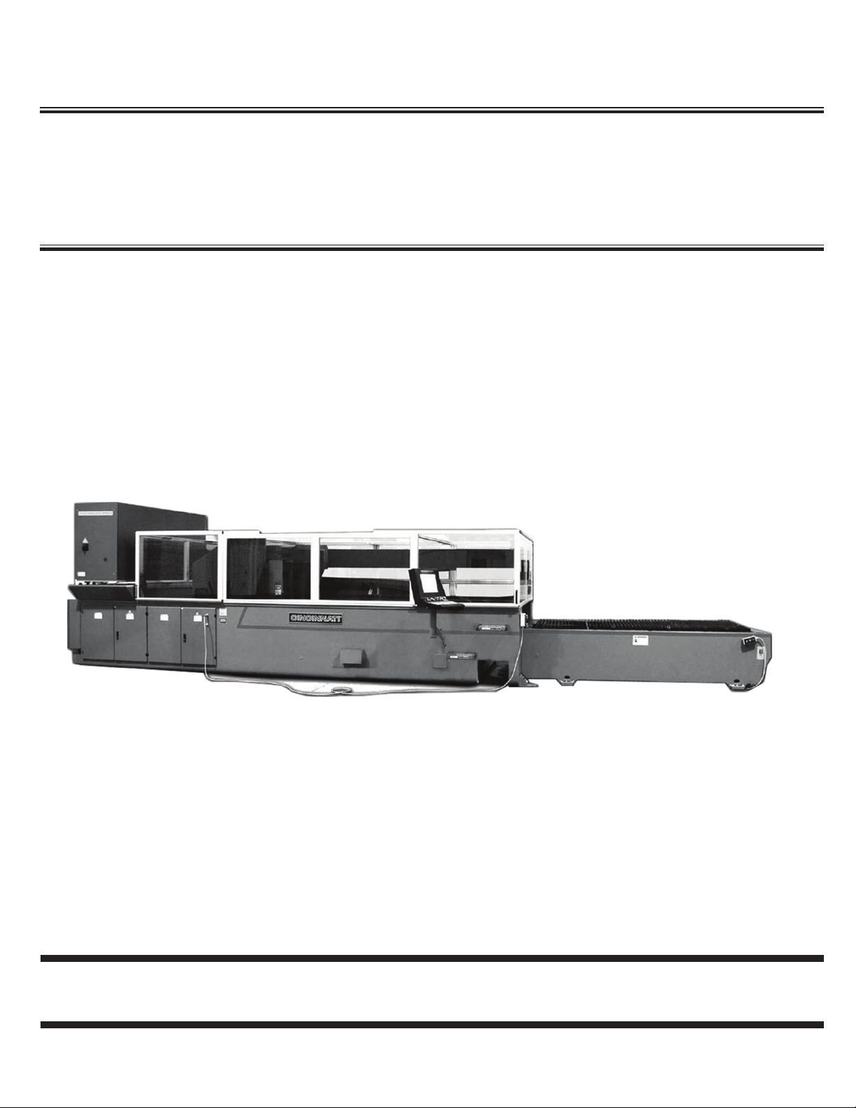
CINCINNATI CL-800 SERIES LASER SYSTEM
The Laser System produces two-dimensional contoured shapes from at material by moving a focused
laser beam along a programmed path. The beam from a stationary laser resonator is directed to a moving
lens by two mirrors mounted on a moving gantry. The workpiece remains stationary while a narrow strip
of material is removed along the path made by the lens. Material is removed by vaporization and melting
where the lens concentrates laser power into a small spot on the workpiece. Assist gas is also used to
control the cutting process.
The mirrors and lens are positioned by the gantry to produce the programmed workpiece geometry. A DSP
(Digital Signal Processor) motion controller commands servo drives to control the gantry motion. The
program is provided by the user and includes commands to specify feedrate, laser power, and assist gas.
The Laser System is equipped with an exhaust system, which draws air down from the cutting area to assist
in the removal of process by-products.
PART QUALITY
The following factors affect part quality:
Machine condition•
Operator ability•
Set-up and Programming•
Quality and type of material•
CINCINNATI machines are designed to be rugged and durable. However, improper adjustment or lack
of maintenance can reduce the quality of parts produced on the machine. The quality of a laser-cut edge
depends on the combination of a uniform laser beam of adequate power, properly focused on the workpiece
with an adequate supply of the correct assist gas, traveling at a speed compatible with the material removal
rate.
Uniform beam quality and power level are most inuenced by the alignment and cleanliness of the optical
elements (internal resonator mirrors, external beam delivery mirrors and the focusing lens).
Critical manual adjustments are: Lens focal point location and lens-to-nozzle centering. The Auto Focus
Cutting Head eliminates manual focal point adjustment.
Part quality depends on the program to command the correct combination of laser power, assist gas, and
feedrate for the material type and thickness being processed. Part accuracy depends on the program for
proper use of kerf width compensation and for selection of feedrate within radius contouring accuracy
limits.
Material quality can affect the repeatability of process parameters. Material with uniform composition,
uniform thickness, and a smooth, clean surface will minimize variations in part quality.

EM-534 (R-03/10)
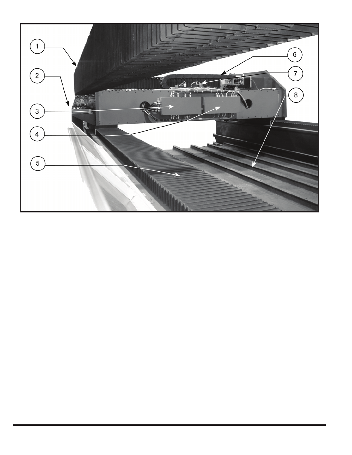
SEcTION 1 IDENTIFIcATION
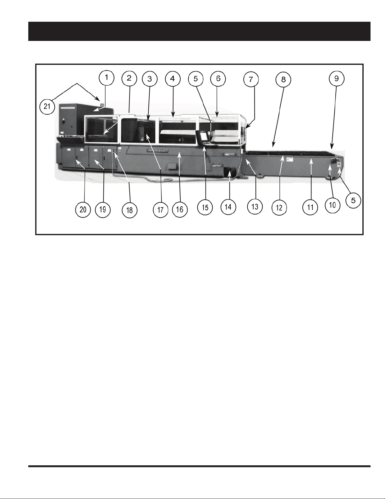
CL-800 SERIES LASER SYSTEM
RESONATOR1.
RESONATOR SAFETY DOOR2.
X-BEAM DELIVERY MIRROR BOX3.
X-AXIS BEAM TUBE4.
E-STOPS5.
OPERATOR SAFETY DOOR6.
SAFETY ENCLOSURE7.
LOWER PALLET8.
LOAD FRAME9.
BALL TRANSFER REMOTE (OPT)10.
MATERIAL SUPPORTS11.
FIGURE 1-1 Front View
MATERIAL CLAMPS12.
REMOTE STATION13.
SCRAP BIN14.
OPERATOR CONTROL STATION15.
MAIN FRAME16.
Y-PLATE17.
REMOTE STATION CONNECTION18.
CONTROL ENCLOSURE19.
POWER ENCLOSURE20.
RESONATOR HIGH VOLTAGE LIGHT21.
1-1
EM-534 (R-03/10)
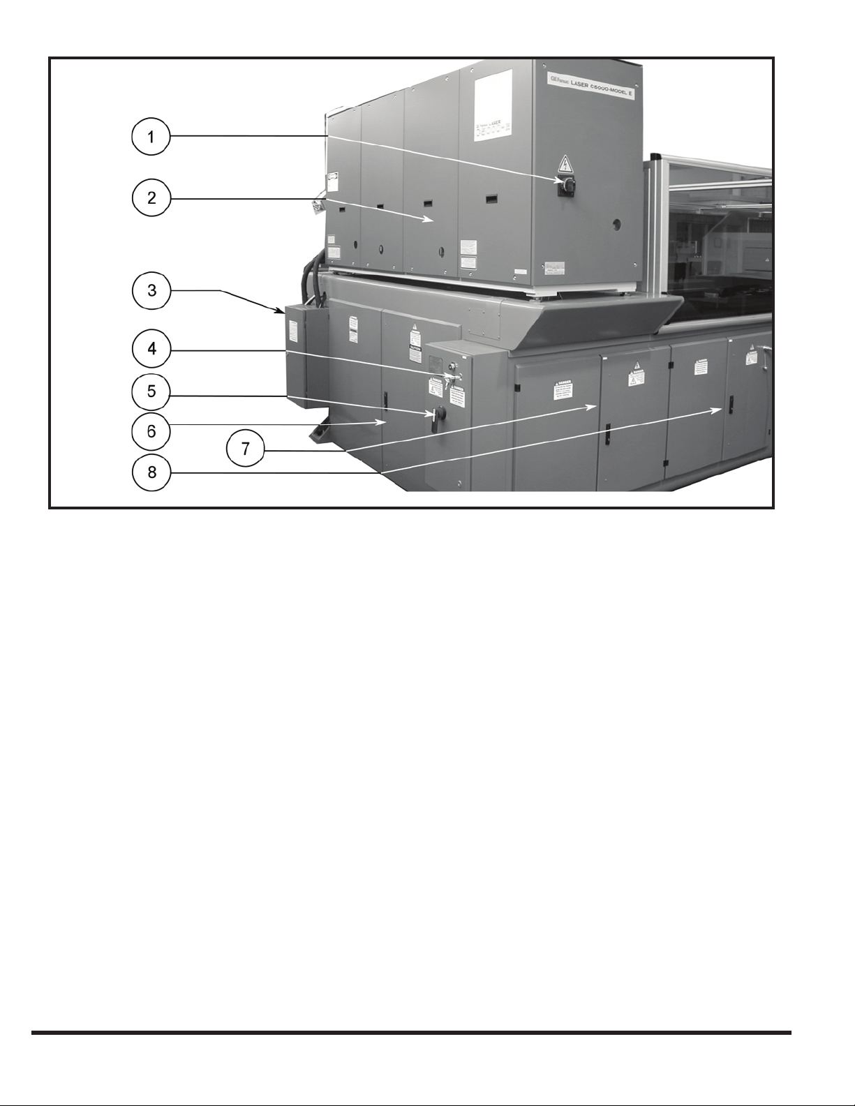
RESONATOR MAIN DISCONNECT1.
RESONATOR2.
GAS AND COOLANT CONNECTION3.
MAIN BREAKER INTERLOCK BYPASS KEY4.
FIGURE 1-2 Rear View
MAIN DISCONNECT5.
MAIN ENCLOSURE6.
POWER ENCLOSURE7.
CONTROL ENCLOSURE8.
EM-534 (R-03/10)
1-2
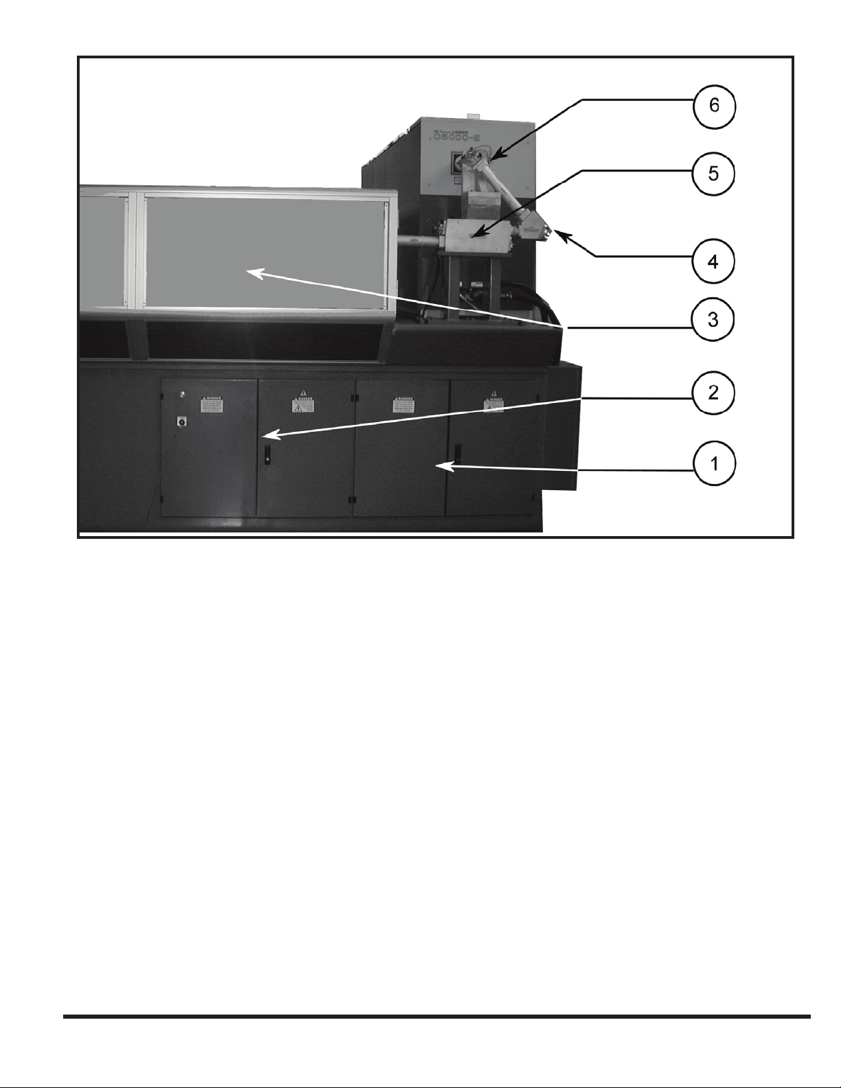
DRIVE ENCLOSURE1.
I/O ENCLOSURE2.
SAFETY ENCLOSURE3.
FIGURE 1-2a Rear View
SECOND EXTERNAL MIRROR (BEAM BENDER4.
COLLIMATOR5.
FIRST EXTERNAL6.
1-3
EM-534 (R-03/10)
X-AXIS BEAM BELLOWS1.
X-AXIS CABLE CARRIER2.
RIGHT GANTRY ENCLOSURE3.
LEFT GANTRY ENCLOSURE4.
FIGURE 1-2b Rear View
X-2 AXIS WAY COVER5.
Y-AXIS CABLE CARRIER6.
ASSIST GAS PROPORTIONAL VALVES7.
SCRAP TRAYS AND STRAP TRAY CAPS8.
EM-534 (R-03/10)
1-4
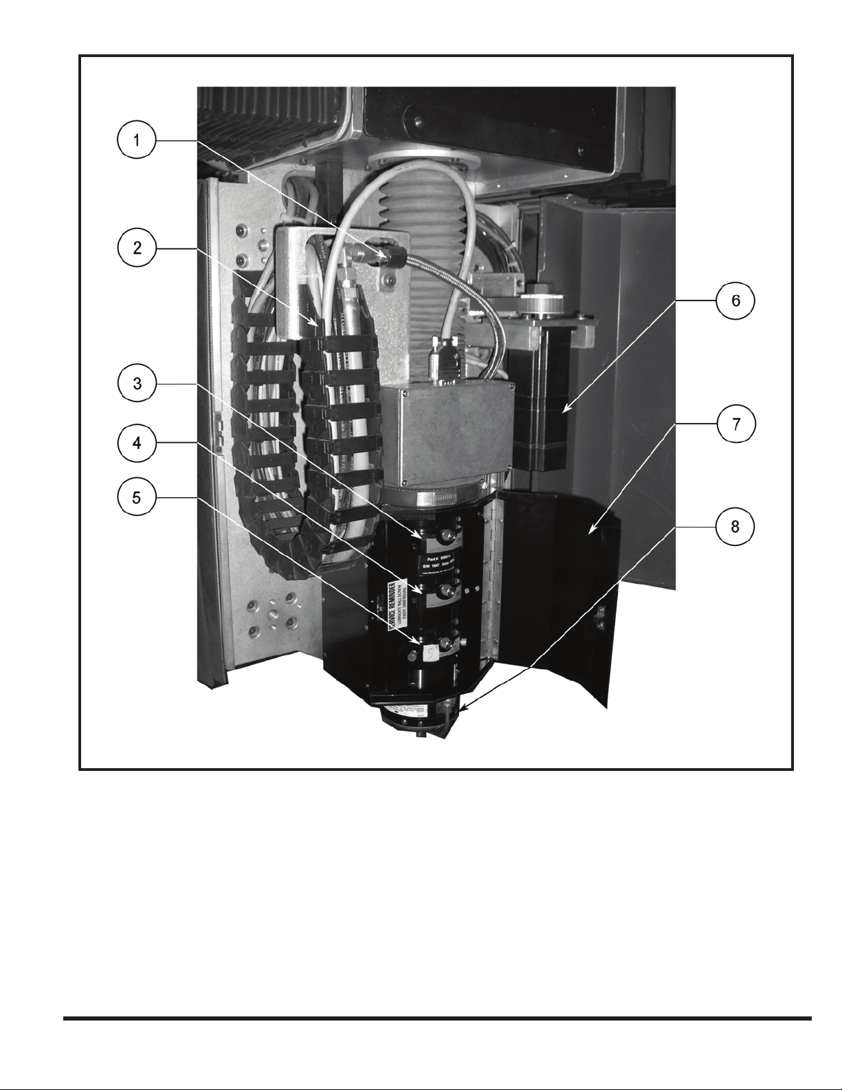
ASSIST GAS HOSE1.
Z AXIS CABLE CARRIER2.
10 INCH LENS DRAWER (EMPTY MANIFOLD SEAL)3.
7.5 INCH LENS DRAWER (EMPTY MANIFOLD SEAL)4.
FIGURE 1-3 Y-Plate and Auto Focus Head Assembly
5 INCH LENS DRAWER (INSTALLED)5.
Z-AXIS MOTOR6.
LENS DOOR7.
LOWER TIP ASSEMBLY8.
1-5
EM-534 (R-03/10)

EM-534 (R-03/10)
1-6
SEcTION 2 INSTAllATION
IMPORTANT: Before proceeding, contact CINCINNATI
Laser Service for pre-installation instructions.
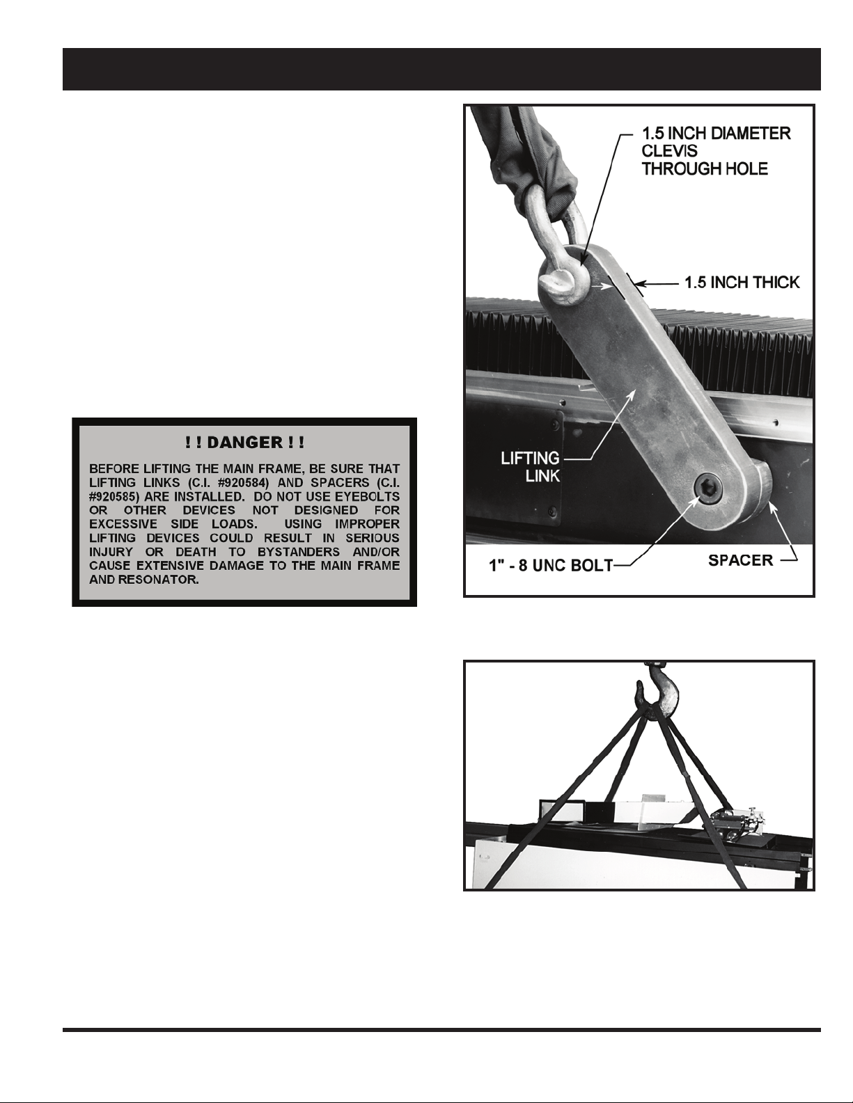
LIFTING AND MOVING
Machine weights are provided in SECTION 4.
The main frame is lifted using four standard lifting clevises
attached to four lifting links (C.I. #920584) with spacers (C.I.
#920585). The four lifting links (supplied by CINCINNATI)
are attached to the inside of the main frame with 1”-8 UNC
SHCS bolts. See Figure 2-1.
When lifting with chains, cables or straps, use the maximum
length possible to reduce the side loading generated at the
lift points. Use spreader bars or intermediate lifting beam if
ceiling height will not allow a high pick.
IMPORTANT: Extreme care must be taken not to subject
the machine to shock loads. The machine must be
lifted and set down gently. Do not allow any weight
to rest on resonator enclosure. Set the machine on its
feet without letting the enclosure “touch down” rst.
The load frame can be lifted using straps with S-hooks at
each of the four outer corners. The S-hooks are hooked in
the access holes located at the bottom of the load frame.
Adequate padding must be used at all points to protect the
machine’s nish. The straps can be gathered and lifted with
a hook attachment. See Figure 2-2
FIGURE 2-1 Lifting Main Frame
FIGURE 2-2 Lifting Load Frame
2-1
EM-534 (R-03/10)
FOUNDATION
A Certied Foundation Plan drawing is provided when the
machine is ordered. This drawing provides the user with
detailed information required to locate the equipment and
the eight machine anchors. The customer should prepare
the eight anchor locations prior to arrival of the equipment.
The eight pads must be pre-leveled to lie in the same plane
within .50 inches (12.7 mm), and the anchor holes should
be drilled as specied on the Foundation Plan drawing.
CINCINNATI INCORPORATED provides anchors, studs,
nuts, and shims for nal leveling.
If the machine is to be installed near shock inducing
equipment such as punch presses, turret punches, etc.,
contact CINCINNATI INCORPORATED.
INSTALLATION OF MACHINE
Remove neoprene shipping feet before setting machine on
the anchor studs.
After setting the machine on the anchor studs, place washers
and nuts on studs, but do not tighten. Installation consists of
the following steps:
Remove lifting clevises and spacers. 1.
Connect the customer-furnished fume exhaust system 4.
to the fume duct exit port.
Complete preliminary leveling procedure described 5.
below.
Install safety mats, using instructions provided with the 6.
machine.
CINCINNATI Service will install the operator control 7.
station and complete nal electrical connections to the
control.
Install gas lines, wiring, and hoses as described in the 8.
pre-installation manual.
CHILLER
The water chiller is a free-standing unit requiring only oor
support. Cooling lines are connected to the main frame
at a central location on the beam delivery side. Hoses are
furnished to connect the chiller when located as shown on
foundation plan. Consult CINCINNATI INCORPORATED
if an alternative chiller location is required. See SECTION
4 for chiller uid specications.
Remove all steel banding and protective wrappings.2.
Install fume fan (optional) and fume duct connecting 3.
to fume plenum with ange and fasteners provided.
Seal connection with a bead of RTV silicone. Make the
electrical connection to the fan drive motor with wiring
provided.
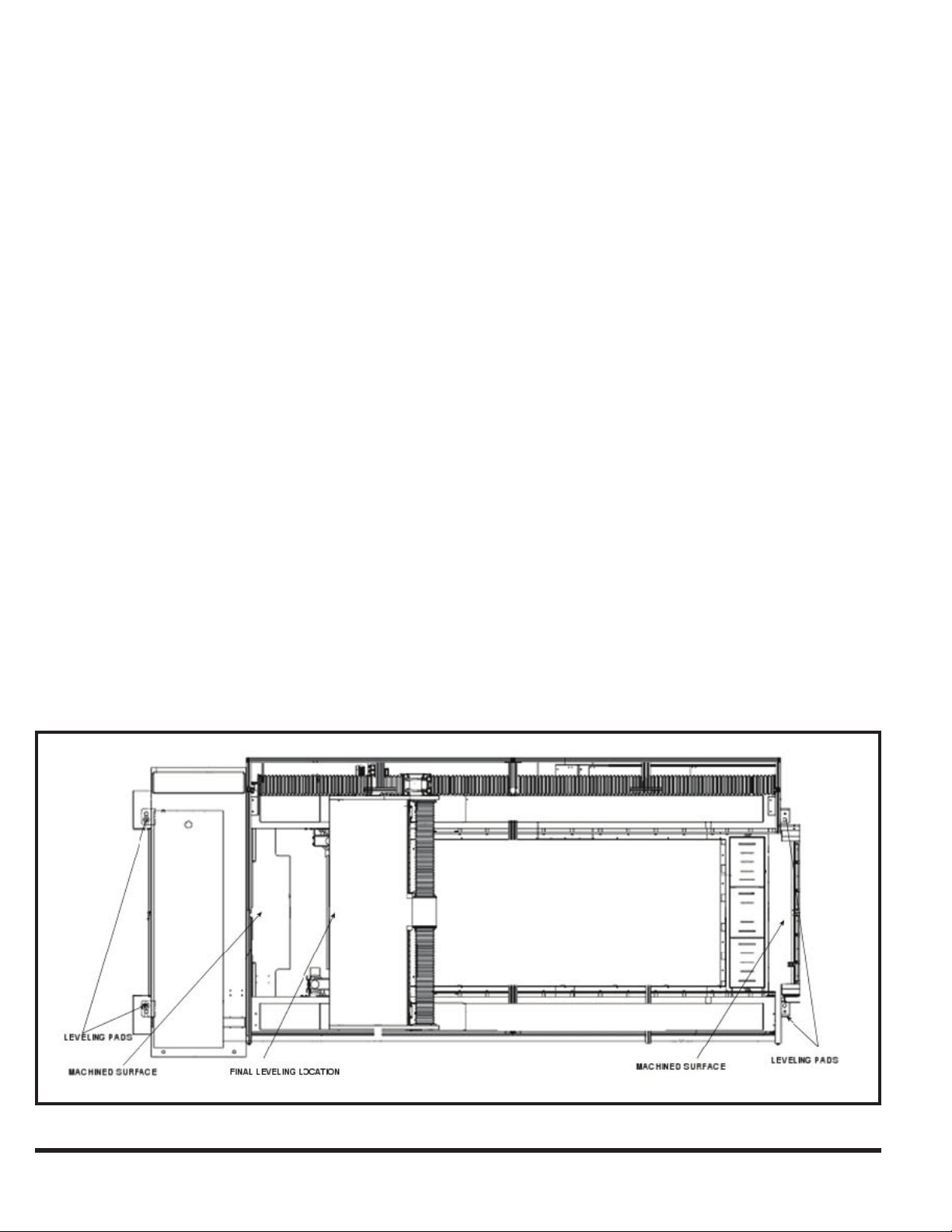
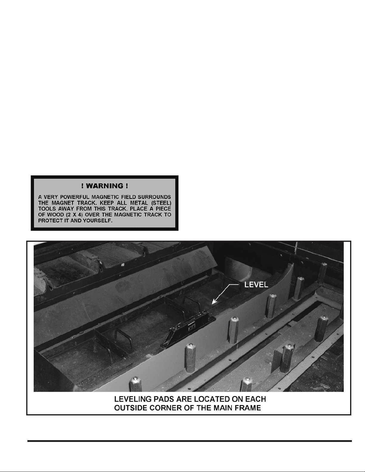
LEVELING
Main frame leveling adjustments are made using jackscrews
provided at the mounting pads. Figure 2-3 shows the
mounting pads. The machine foot mounting pads are
located on the outside surface of the main frame in the four
corners.
EM-534 (R-03/10)
FIGURE 2-3 Main Frame Leveling Adjustments
2-2
Slotted shims are inserted between the machine foot and
steel spacer block as shown on the Foundation Plan drawing.
After shims are inserted, jackscrews are to be backed off or
removed. The procedure for leveling is described in the next
sections.
PRELIMINARY LEVELING
To check cross-leveling, place a precision level 1.
on machined pads on each end of main frame. For
preliminary leveling, a level with .004”/ft. precision is
sufcient (0.33 mm per meter). See Figures 2-3 and 2-4.
Lift machine with jackscrews and shim under mounting
feet (shims are provided).
Longitudinal level is checked on the top of the X-Axis 2.
guide way. Adjust as described above. (See Figure
2-5.) Longitudinal leveling does not require a precision
level.
FINAL LEVELING
Final leveling should be done with a CINCINNATI
INCORPORATED Service Representative present.
The purpose of nal leveling is to ensure that the gantry does
not rotate about the X-axis as the gantry moves from end-toend. Excessive rotation will cause laser beam misalignment
during operation.
Use a 15” (380 mm) precision spirit level with a 1.
sensitivity of .0005”/ft. (0.04 mm per meter).
Place the level on the top of the gantry and position 2.
the gantry at X = 0. See Figure 2-6. The gantry may be
moved by manually pushing it when drives are off, or
by using JOG mode when drives on.
The top of the gantry is not machined. Therefore, it 3.
will be necessary to shim one or both ends of the level
to establish a reference reading and make the level
sit solidly in place. Paper shims can be used for this
purpose.
FIGURE 2-4 Cross leveling (Preliminary)
2-3
EM-534 (R-03/10)
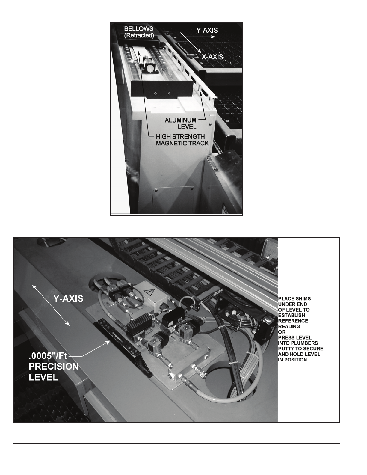
FIGURE 2-5 Longitudinal leveling
EM-534 (R-03/10)
FIGURE 2-6 Final leveling with precision level
2-4

Observe the position of the bubble while moving the 4.
gantry from X = 0 to X = Maximum travel. The maximum
acceptable deviation is one division of the level (.0005”/
ft. or 0.04 mm per meter) as the gantry moves from
end-to-end. This ensures that the frame is not in a twist.
Adjust as described above, using jackscrews to add or
remove shims under mounting feet.
When Step 4 is complete, lightly tighten anchor nuts and 5.
recheck level as specied in Step 4. Verify that jacking
screws are backed off and not supporting the machine.
The standard electrical input is 460 volt, 3 phase and
50/60 hertz. The machine must be properly grounded in
accordance with the National Electric Code NFPA 70, 2002
edition, article 250, sections 50 through 70. CINCINNATI
INCORPORATED recommends using an individual
electrode per article 250.52 (5) to avoid interference from
other equipment. Place ground electrode as indicated
on foundation plan drawing. Do not start the machine
until the SAFETY section of this manual has been read
thoroughly and a CINCINNATI INCORPORATED Service
Representative is present.
Tighten the anchor nuts.6.
Repeat Step 4 as a nal level check.7.
ELECTRICAL CONNECTION
Each Laser System customer is supplied a complete set of
Foundation Plan drawings prior to machine shipment. The
electrical load requirements and connection points are called
out on these drawings. Be certain that a suitably sized wire
is brought to the main disconnect and the proper voltage is
supplied.
The machine controls have been designed to operate
satisfactorily with good quality incoming electrical power.
It is important that the electrical power be free of excessive
noise and power uctuations. Refer to the pre-installation
instructions for details of input power requirements.
SAFETY DEVICES
DO NOT START MACHINE UNTIL YOU HAVE
THOROUGHLY READ THE SAFETY SECTION
OF THIS MANUAL AND A CINCINNATI
INCORPORATED SERVICE REPRESENTATIVE IS
PRESENT.
2-5
EM-534 (R-03/10)

EM-534 (R-03/10)
2-6

SEcTION 3 SAFETY
SAFETY IS EVERYONE’S JOB
The CINCINNATI Laser System manufactured by
CINCINNATI INCORPORATED has been designed to
meet the highest order of reliability and ease of operator use.
This system has been certied under Federal Regulations
21 CFR, subpart J, as a Class 4 Laser product as required
by the Federal Radiation Control for Health and Safety
Act of 1968. This certication is on le with the Food and
Drug Administration “Center for Devices and Radiological
Health” (CDRH) Division, Ofce of Compliance, 2098
Gaither Road, Rockville, Maryland 20850.
CINCINNATI INCORPORATED recommends the
customer read and understand the requirements of the
American National Standard ANSI B11.21 entitled “Safety
Requirements for Design, Construction, Care and Use of
Machine Tools Using Lasers for Processing Materials” and
ANSI Z136.1 entitled “American National Standard for
Safe Use of Lasers”. They are available from the American
National Standards Institute, 25 West 43rd Street, New
York, New York 10036.
For additional safety information, we recommend you:
Obtain applicable safety data from:1.
National Safety Council, 1121 Spring Lake Drive, a.
Itasca, Illinois 60143-3201
The Laser Institute of America, Suite 128, 13501 b.
Ingenuity Drive, Orlando, Florida 32826.
Determine your responsibilities under your state and 2.
local safety codes.
Request assistance from the loss prevention department 3.
of your workmen’s compensation carrier.
Personnel responsible for your Laser System operator
training program, maintenance, and manufacturing
operations must read and understand this Operation, Safety
and Maintenance manual. No one should set up, operate or
maintain this Laser System until they thoroughly understand
it and know how to do their job safely. Read this manual in
its entirety.
INTRODUCTION TO LASER SAFETY
The laser beam is a strong, highly directional beam of
energy that, if directed, reected or focused upon an object,
will be partially absorbed. This absorbed energy can raise
the temperature of the object enough to cause material
changes at the point where the laser beam hits the object.
This process can also produce adverse biological effects in
human tissue.
A BRIEF DISCUSSION ON RADIATION
Radiation is energy radiated or given off in the form of
waves or particles. It is a general term used to describe
energy emitted from a wide range of sources. Some
sources are man-made such as radio waves and some are
made naturally such as the rays coming from the sun. To
keep track of all the various kinds of radiation, scientists
developed a system to separate radiation by the length of
the wave (or frequency) being sent out by the source. This
is called the “electromagnetic spectrum”. This spectrum
covers the entire range of energy wavelengths from the
very short gamma rays to the much longer wavelength of
commercial electricity sent out from your electric company
(i.e. 60 cycle current).
All forms of electromagnetic radiation travel at the speed of
light, but at differing frequencies. The longer the wavelength
is, the lower the frequency. The energy transmitted by
radiation is also related to its frequency. Higher frequency
radiation can transmit greater energy.
Some radiation interferes with the internal energy that
holds atoms together as molecules. If the energy of a ray
of radiation is great enough, it will attract electrons away
from an atom or add additional electrons to it. This is
called “ionizing” radiation. X-rays are an example of this
type of radiation. CINCINNATI Laser Systems do not use
“ionizing” radiation.
Radiation that lacks the energy to deform atoms is called
“non-ionizing” radiation. This is the type used in a
CINCINNATI LASER SYSTEM. The source used to
generate the laser beam is carbon dioxide gas (CO
laser beam is emitted in a continuous wave (CW) at a xed
wavelength of 10.6 micrometers. This wavelength is in the
far-infrared region of the electromagnetic spectrum. The
beam is invisible and has high heat energy.
Non-ionizing radiation can cause harm. This is a result of
the energy being absorbed and raising the temperature of
the part of the body being hit. Over time, the heat energy
being absorbed will reach a harmful level. This injury is
similar to the burn you can get from a bonre by standing
too close for too long or the burn you can get from being out
too long in the sun.
If the body part exposed to “non-ionizing” radiation is the
hardened, dead-cell tissue of the outer skin, minor harm will
be done. A reddening of the tissue and mild soreness might
be the only result. However, if that same radiation energy
gets inside the body to less well-protected tissue, the tissue
may not only be heated, but may become permanently
damaged as well.
). The
2
3-1
EM-534 (R-03/10)
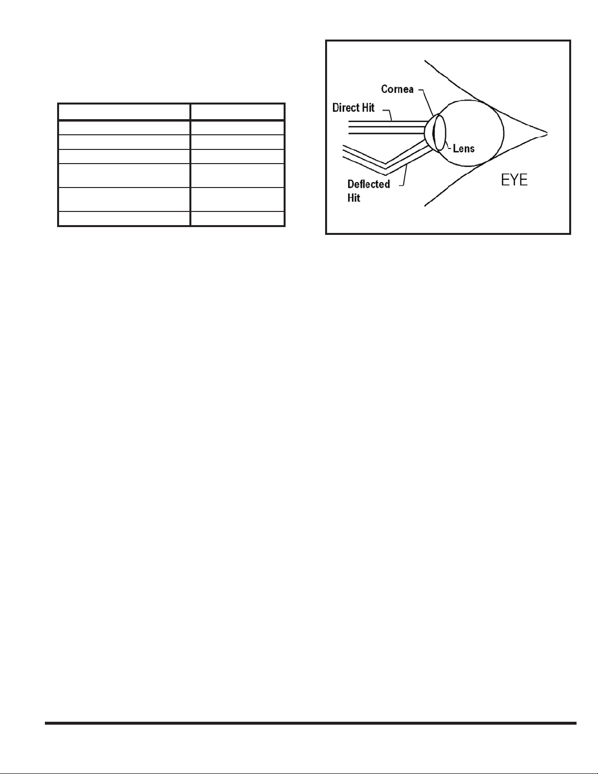
For example, the eyes are very susceptible to radiation. The
cells of the cornea and retina are not protected by a layer of
dead skin and thus can be damaged much easier than your
skin. The eye should always be protected from radiated
energy. Eye hazards and eye protection are covered in more
detail later in this section.
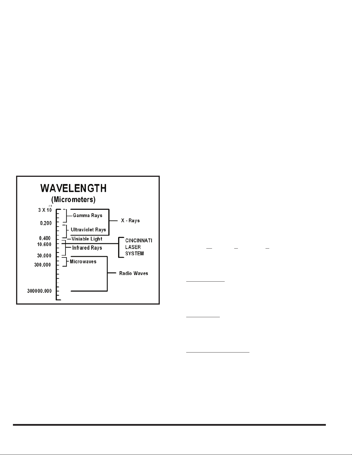
Figure 3-1 is a chart of the electromagnetic spectrum.
The CINCINNATI (CO
) LASER SYSTEM operates at a
2
wavelength of 10.6 micrometers. As you can see from the
chart, this wavelength is in the infrared range. Breaking the
infrared range down further, the radiation generated from
a carbon dioxide gas laser is considered to be in the farinfrared range.
This brief introduction has been prepared to alleviate any
unwarranted worries regarding laser radiation safety. A more
detailed discussion can be obtained in OSHA Publication
8-1.7 entitled “Guidelines for Laser Safety and Hazard
Assessment”.
International Electrotechnical Commission (IEC) has been
developing laser safety standards.
In 1968, the U.S. Government passed a law regulating
products used in the United States that radiate energy.
The law is the “Radiation Control for Health and Safety
Act of 1968”. This law sets standards of performance for
electrical products that emit radiation. These are called
U. S. Federal Laser Product Performance Standards or
FLPPS. Manufacturers use FLPPS to ensure the design and
manufacture of their product properly controls radiation
hazards before the product is released to their customers.
Examples of some of the products covered under this law
are x-ray machines, microwave ovens, hair dryers and all
types of lasers.
The Federal Standards covering Lasers and Laser Products
(i.e. devices or machines containing a laser) are covered
in the Federal Register at 21 CFR Part 1040. In these
standards, the level of radiation accessible to persons is
used to group lasers into one of four classes. The classes
are Class 1, Class 2, Class 3, and Class 4. These classes or
risk categories establish the hazard controls required in the
product’s design before a manufacturer can turn a product
over to a user.
FIGURE 3-1 Electromagnetic Spectrum
SAFETY STANDARDS AND PUBLICATIONS
There are a wide variety of laser safety standards and
publications. These include regulations of the Federal
Government, and of several state and local governments.
Additionally there are non-regulatory standards, such as the
ones of the American National Standards Institute (ANSI)
and of the American Conference of Governmental Industrial
Hygienists (ACGIH). Internationally, the World Health
Organization (WHO) has laser safety guidelines, and the
Research studies, along with an understanding of the hazards
of sunlight and conventional, man-made light sources have
permitted scientists to establish safe exposure limits for
nearly all types of laser radiation. Laser safety specialists call
these limits Maximum Permissible Exposures (MPE’s).
Of the standards and publications that apply to users of
CINCINNATI Laser Systems, three will be most helpful:
ANSI B11.211. “American National Standard for
Machines Using Lasers”. The contents of this standard
came from the users and manufacturers of the machines
that use laser generated beams to process material.
ANSI Z136.12. “American National Standard for Safe Use
of Lasers”. This standard, which is technical in content,
was developed by the research and health community to
cover all types of lasers and laser applications.
OSHA Publication 8-1.73. “Guidelines for Laser Safety
and Hazard Assessment”. This was developed for
OSHA eld personnel to help in their job of enforcing
workplace safety standards.
EM-534 (R-03/10)
3-2

LASER HAZARD CLASSIFICATION
As previously indicated, laser products are placed into one
of four classes. These are:
Class 1 A Class 1 laser is considered safe based upon
current medical knowledge. This class includes all lasers
or laser systems which cannot emit levels of optical
radiation above the exposure limits for the eye under any
exposure conditions inherent in the design of the laser
product.
Class 2 A Class 2 laser or laser system must emit a visible
laser beam, whose natural brightness will limit exposure
by making the eye turn away. Momentary viewing is not
considered hazardous since the average radiant power
limit on this type of device must not exceed 1 milliwatt
(mW).
Class 3 A Class 3 laser or laser system can emit any
wavelength, visible or non-visible. The Class 3 laser
is divided into two subclasses, Class 3a and Class 3b.
These lasers and laser systems are not considered a re
hazard or a serious skin hazard. Any CW (continuous
wave) laser that is not a Class 1 or Class 2 is a Class 3
device if its output power is 0.5 watts or less. Since the
output beam of such a laser is denitely hazardous when
the beam is allowed to directly enter the eye, control
measures for the Class 3 lasers and laser systems center
on eliminating this possibility.
Class 4 A Class 4 laser or laser system is any that exceeds
the output limits (Accessible Emission Limits, AEL’s) of
a Class 3 device. As would be expected, these lasers may
be a re and skin hazard or a diffuse reection hazard or
both. Very stringent control measures are required for a
Class 4 laser or laser system.
Because of the power needed to cut metal, all lasers used to cut
metal are Class 4 lasers. Some Class 4 lasers are embedded
in enclosures or rooms and called Class 1 laser products or
Class 1 laser systems. However, control measures must still
be established to insure that the enclosure is maintained and
that proper operating procedures are followed.
CONTROL MEASURES
The CINCINNATI Laser System has been designed
and manufactured using the highest engineering control
measures practical. However, even these high standards
have limitations. Laser safety requirements call for
administrative and procedural controls to be incorporated
in the use of lasers in order to minimize or eliminate the
potential of personal injury during laser operation.
Laser safety experts have determined the best way to control
hazards presented by laser products is to establish a clear
plan of hazard control with specic responsibilities spelled
out for all workers involved. The plan has four (4) worker
categories. The Laser Safety Ofcer (LSO) is one category
and the other categories are for personnel working in laser
operations, plant maintenance and laser service.
LASER SAFETY OFFICER
When an organization uses powerful laser products such as
those strong enough to cut metal, it is recommended that
someone in the organization be designated the Laser Safety
Ofce (LSO). This is especially true when dealing with
Class 4 lasers whether they are embedded in a full enclosure
and called Class 1 systems or not.
The LSO should be an employee who is part of the
management organization. The LSO must be given the
responsibility and authority to monitor and enforce the
procedures established for controlling laser hazards. Unless
a great number of laser products are involved, this will not
be a fulltime job but daily auditing of work procedures is
often a good idea. The LSO is responsible for seeing that
written standard operating procedures (SOP) for the laser
system are available. The information needed to establish
these SOP’s will come from the material provided by the
laser system manufacturer, auxiliary equipment providers,
and company safety rules. Each operator, maintenance
person, or laser service person should have access to these
SOP’s and fully understand their content.
OPERATING PERSONNEL
These people are responsible for the productive use of
the laser cutting system over the full range of its intended
function. These persons should be thoroughly familiar with
all operating controls, adjustments, and hazards associated
with their function.
MAINTENANCE PERSONNEL
Laser safety procedures classify Maintenance level tasks
as those done on machinery when the laser beam hazards
are not present. Therefore, maintenance personnel are
responsible for procedures that are completed in and around
a laser system with the laser power off. Maintenance
personnel should be thoroughly trained in the performance
of those procedures.
3-3
EM-534 (R-03/10)
SERVICE PERSONNEL
Service personnel do the work required to maintain the
laser system while the laser beam is active. They must have
the complete knowledge of laser hazards and the controls
provided by the system manufacturer for their protection
from those hazards. They are responsible for doing the
procedures and adjustments described in the manufacturer’s
service manual such as Mode Burns, Tape Shots and Mirror
Alignments. During these tasks, the laser beam needs to
be available and therefore exposure to the hazards of the
beam is possible. To get to the mirrors and beam locations,
the service level worker often must override or defeat the
protection provided. The duty of a service person requires
a higher level of training and education than that of the
maintenance function.
SAFETY PROGRAM
A strong commitment from management must exist in
order for an effective safety program to be established with
personnel involved in the use of the CINCINNATI Laser
System. Additional information concerning this topic can
be located in the American National Standard B11.21 &
Z136.1. Refer to Appendix D of the ANSI Z136.1 standard
for a guide for organizing and implementing a laser safety
and training program.
process that takes place in a laser. Stimulated emission
occurs when the energy released from one atom interacts
with another atom that is still excited. The interaction
stimulates the excited atom into releasing its own energy
as light. Most of the light produced by stimulated emission
has the same frequency and same phase as the stimulating
light. It also travels in the same direction, and so it combines
with and amplies the triggering light. Such light is called
coherent radiation.
LASER TYPES
There are four major types of lasers. The difference between
them is the material used inside the laser that will emit the
energy after being excited. These four types are solid-state
lasers, gas lasers, dye lasers, and semi-conductor lasers.
CINCINNATI Laser Systems use gas type lasers to generate
the cutting beam and gas and semi-conductor lasers to
generate the positioning beam when that feature is supplied.
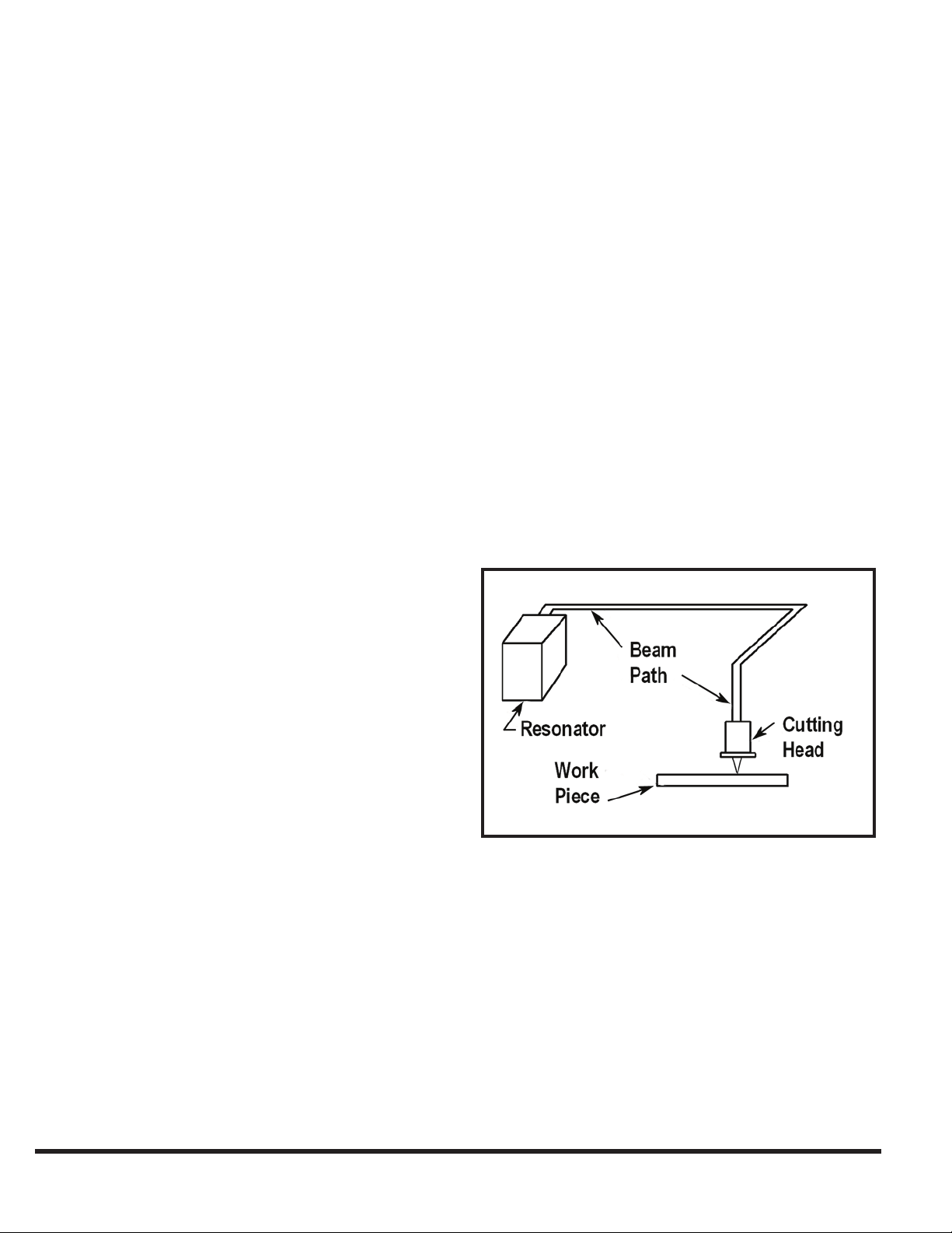
In all cases (i.e. for cutting or positioning), the actual lasergenerating unit is located at one end of the CINCINNATI
Laser System and the beam is directed to the cutting head
through an enclosed beam tube. See Figure 3-2.
EXPLANATION OF LASER RADIATION
Light is a form of energy that is released from individual
atoms or molecules in a substance. To understand how a
laser works, it is necessary to know something about the
nature of atoms and how they interact with light and other
forms of energy.
Every atom is a storehouse of energy. The amount of energy
in an atom depends in part on the motion of the electrons
that orbit the atom’s nucleus. When an atom absorbs energy,
the energy levels of the electrons increase and the atom is
said to be excited. The atoms of a substance become excited
when they absorb heat, light, or other forms of energy that
pass through the substance. An excited atom can return to
its normal energy level by releasing its excess energy in the
form of light. When this release of light occurs randomly, it
is called spontaneous emission.
In spontaneous emission, excited atoms release light
irregularly. As a result, the light has different frequencies,
different phases, and travels in different directions. Light
released in this way is called incoherent light. Such light is
produced by the sun and by ordinary electric light bulbs.
FIGURE 3-2 Beam Path
The enclosure at one end of the CINCINNATI Laser System
is the laser resonator where the laser beam is created. An
electronically actuated shutter system is used to allow the
beam to exit the resonator and enter the beam tube. At this
point, the beam is approximately 1.0” (25 mm) in diameter.
The beam is then directed to the laser cutting head by a
series of special mirrors. After the beam enters the cutting
head, the lens will focus it down to a point as the beam
travels out of the nozzle and onto the work piece.
Excited atoms also may release light systematically. This
kind of release, called stimulated emission, is the main
EM-534 (R-03/10)
3-4
In order to cut (vaporize) steel you need to generate a power
density of over 2 million watts per square centimeter. To
help visualize this concentration of power, Table 3-1
compares power densities of various conditions.
Condition Power Density
Sunlight on the earth’s surface 0.10 w/cm
100 watt light bulb surface 1.0 w/cm
Soldering Iron Tip 100 w/cm
4000-watt laser beam, 1.00”
(25.4 mm) diameter.
4000-watt laser beam, 0.010”
(0.254 mm) focus spot diameter.
Steel Threshold 2 million w/cm
TABLE 3-1 Power Density Comparisons
800 w/cm
8 million w/cm
2
2
2
2
2
2
Gas lasers have several power sources, including chemical
reactions, electric current, electron beams, ultraviolet rays
and radio frequency excitation. Most gas lasers produce a
continuous beam of light. Gas lasers can produce beams
of higher average power than solid lasers because the gas
cools the laser as it ows through the tube. Light from a
gas laser has a narrower frequency range than light from a
solid laser.
The CINCINNATI Laser System can be provided with a
second laser used for positioning. The positioning laser is a
diode laser with very low power. It is located in the resonator
cabinet and produces a visible red beam when turned on.
Due to the visible nature of this beam and its power level,
the positioning laser is designated as a Class 2 or Class
3a laser product depending on the type of laser furnished.
Since Class 2 and Class 3a laser beams are considered a
chronic viewing hazard, the laser system includes signs
warning personnel not to stare into the red beam.
FIGURE 3-3 The Eye
The type and style of eye protection to use should be
worked out with the supplier of your shop eye protection. In
general, the normal polycarbonate safety glasses with side
shields used in metal working shops and meeting the ANSI
Z87 Standard will provide all the protection necessary from
reected beams for operating and maintenance personnel.
Their work should not expose them to the possibility of
direct beam exposure. The procedures established for
service personnel are designed to protect them from direct
beam exposure. However, it is recommended that their
safety glasses have a protective optical density of 4.
Staring at the cutting plume is not necessary or advisable.
The light energy being sent out by the cutting process is
a mixture of many wavelengths. Besides the reection of
the laser beam there is the scattered radiation of the cutting
process. The plume emits visible light and ultraviolet
light.
HAZARDS - CINCINNATI LASER SYSTEMS
EYE HAZARDS
The beam of a CINCINNATI Laser System is a potential eye
hazard. If the beam directly or indirectly hits the eye, there
is a potential for injury to several different areas, depending
upon which eye part absorbs the most radiant energy.
Laser radiation in the far-infrared region will be absorbed in
the front surface of the eye. Thus, if the eye is not protected,
it may receive damage to the cornea and lens from direct
or reected laser beam exposure. Therefore, all operation,
maintenance and service personnel working at the
CINCINNATI Laser System must wear eye protection.
It is the users responsibility to establish and enforce an eye
protection program.
SKIN HAZARDS
Laser radiation striking the skin is reected, absorbed
and transmitted; the percentage of each depends upon the
characteristics of the skin at the wavelengths of concern.
Effects on the skin from absorbed radiation may vary from
mild redness to blistering and/or charring, depending upon
the total energy absorbed and the rate at which it is absorbed.
Unnecessary exposure of the skin to laser radiation should
be avoided regardless of the level of radiant energy.
3-5
EM-534 (R-03/10)
The CINCINNATI Laser System has been tested and found
to have no detectable x-ray emissions and related hazards.
In general, the hazards presented by the CINCINNATI
Laser System will be severe burns, lacerations and possible
amputation if members of the body are exposed to the direct
beam or reected beams of high energy. The design of the
Laser System provides engineered protection from these
hazards for personnel while properly using this equipment.
This basic design should not be altered or modied in any
manner.
NOMINAL HAZARD ZONES
Safety standards dene a laser’s Nominal Hazard Zone
(NHZ) as “the space within which the level of the direct
reected or scattered radiation during operation exceeds the
applicable Maximum Permissible Exposure (MPE)”. When
considering a CINCINNATI Laser System, the radiation
hazard is the laser beam which is strong enough to cause
severe burns to the surface of the eye or skin if a worker is
directly in its path or hit by the beam as it is reected off
machine or piece part surfaces. The nominal hazard zone
is the space in all directions away from the beam where
the heat from the beam is strong enough to cause injury.
The NHZ can be calculated using the formulas and charts
contained in the ANSI Z136.1 Safety Standard and used in
this manual.
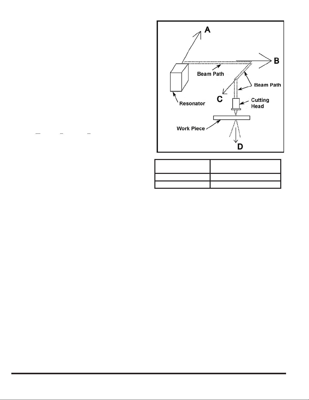
During piece part cutting, the beam is fully contained within
the beam tube and exits only at the cutting head. Figure 3-4
shows the usual path of the laser beam. On some models,
this path is slightly changed due to different positions of
the laser resonator or additional features enclosed within
the path. At the cutting head, the lens focuses the beam
downward to a spot as the beam exits to process material.
BEAM EXPOSURE CATEGORIES
There are three categories of potential laser beam exposures
on any laser cutting system:
Intra-beam Exposure•
Specular Reection Beam Exposure •
Diffuse Reection Beam Exposure •
DIRECTION HAZARD DISTANCE
A, B or C 2439.1 Ft. (743.4 m)
D 56.1 Ft. (17.1 m)
FIGURE 3-4 Uncontained beam hazard distance
The CINCINNATI Laser System’s design deals with beam
exposure categories in various ways:
Intra-beam (Direct) Exposure occurs when an object is •
in the beam’s path. See directions A, B, C & D in Figure
3-4.
The fully enclosed beam tube guards this potential
exposure, by appropriate interlocks and warning labels
on service access panels. After the beam leaves the lens,
the Laser System’s two-axis motion system provides
for a xed downward beam direction. Automatic beam
shutoff occurs through redundant mechanisms if the
cutting head is knocked off or rises more than 1-1/2”
(38 mm) above the top of the cutting pallet.
Specular Reection occurs when the beam reects off a •
mirror-like object.
EM-534 (R-03/10)
This mirror-like reection of the focused beam off a
work piece is directed upward into the cutting head and
gantry due to the xed downward beam direction and
the horizontal work piece orientation.
Diffuse Reection occurs when the beam reects off •
the work piece during cutting or when the unfocused
beam hits an object.
3-6
 Loading...