

Page 1

PROGRAMMING MANUAL
AN OPERATION SUPPLEMENT MANUAL FOR THE
CINCINNATI CL-707, CL-7A, AND CL-800
LASER SYSTEM WITH PC-BASED CONTROL
EM-423 (R-02/11) COPYRIGHT 2011
CINCINNATI INCORPORATED
Page 2

Page 3

PROGRAMMING CONTENTS
SECTION 1 STANDARD G-CODES
1.00 G00 RAPID TRAVERSE MOVE...........................................................1-1
1.01 G01 LINEAR MOVE.............................................................................1-1
FEEDRATE.......................................................................................... 1-2
1.02 G02 CLOCKWISE ARC .......................................................................1-2
1.03 G03 COUNTERCLOCKWISE ARC......................................................1-2
RECOMMENDED ARC FEEDRATE...................................................1-3
1.04 G04 DWELL......................................................................................... 1-3
1.09 G09 EXACT STOP (ONE BLOCK) ......................................................1-4
1.20 G20 INCH MODE.................................................................................1-4
1.21 G21 METRIC MODE............................................................................1-4
1.31 G31 POSITION CAPTURE MOVE....................................................... 1-4
1.40 G40 CANCEL KERF COMPENSATION.............................................. 1-4
1.41 G41 LEFT SIDE COMPENSATION..................................................... 1-4
1.42 G42 RIGHT SIDE COMPENSATION...................................................1-4
1.50 G50 CANCEL SCALING...................................................................... 1-5
1.51 G51 WORK COORDINATE SYSTEM SCALING.................................1-5
1.52 G52 LOCAL WORK COORDINATE SYSTEM ................................ 1-6
1.53 G53 RAPID MOVE TO MACHINE COORDINATES............................1-6
1.54 G54 THROUGH G59............................................................................1-6
1.61 G61 EXACT STOP MODE...................................................................1-7
1.64 G64 CANCEL EXACT STOP MODE ...................................................1-7
1.65 G65 SUB-PROGRAM CALL ................................................................1-7
1.68 G68 WORK COORDINATE SYSTEM ROTATION ........................1-7
1.69 G69 CANCEL ROTATION ...................................................................1-7
1.90 G90 ABSOLUTE MODE.......................................................................1-8
1.91 G91 INCREMENTAL MODE................................................................1-8
1.92 G92 WORK COORDINATE SYSTEM SETTING.................................1-8
SECTION 2 CUSTOM G-CODES
2.84 G84 PIERCE AND START CUT ..........................................................2-1
2.85 G85 START CUT WITHOUT PIERCE ................................................. 2-1
PIERCE OPTIONS (G84 T_)...............................................................2-1
AIRBLAST ...........................................................................................2-1
2.89 G89 PROCESS PARAMETERS..........................................................2-2
2.102 G102 ADDITIONAL PARAMETER SETTINGS ................................... 2-3
2.103 G103 RAMPED PIERCE SETTINGS................................................... 2-4
2.120 G120 DISABLE NON-STOP CUTTING ...............................................2-4
2.121 G121 ENABLE NON-STOP CUTTING ................................................2-4
SMART RAPIDS..................................................................................2-5
2.123 G123 PROGRAMMABLE BLEND........................................................ 2-6
2.124 G124 DEFAULT BLEND...................................................................... 2-6
2.125 G125 AUTO BLEND.............................................................................2-6
SECTION 3 M-CODES
3.00 M00 PROGRAM STOP........................................................................3-1
3.01 M01 OPTIONAL STOP ........................................................................3-1
3.02 M02 END OF PROGRAM.................................................................... 3-1
3.30 M30 END OF PROGRAM WITH REWIND ..........................................3-1
3.35 M35 BEAM OFF...................................................................................3-1
3.36 M36 SERVO HOLD FOR NONCONTACT Z-AXIS.............................. 3-1
3.37 M37 BEAM OFF, GAS OFF AND SHUTTER CLOSE .........................3-1
3.38 M38 TIMED NONCONTACT SERVO HOLD ....................................... 3-2
3.41 M41 COMMAND Z-AXIS DOWN TO CUT POSITION.........................3-2
3.42 M42 RETRACT Z-AXIS........................................................................3-2
3.43 M43 LOWER PALLET SPECIAL FUNCTION......................................3-2
3.44 M44 CANCEL LOWER PALLET SPECIAL FUNCTION ......................3-3
3.45 M45 APPLY OPTIONAL STANDOFF FOR CUTTING ........................ 3-3
3.47 M47 RAISE Z-AXIS, OPTIONALLY BY DISTANCE ............................3-3
EM-423 (R-02/11) iii
Page 4

3.48 M48 FEEDRATE OVERRIDE DISABLE...............................................3-3
3.49 M49 FEEDRATE OVERRIDE ENABLE................................................3-3
3.50 M50 SWITCH PALLETS.......................................................................3-3
3.51 M51 AUXILIARY TIMED OUTPUT.......................................................3-4
3.67 M67 APPLY OPTIONAL ASSIST GAS PRESSURE .......................3-4
3.98 M98 SUB-PROGRAM CALL WITH NO ARGUMENTS........................3-4
3.99 M99 END SUB-PROGRAM AND RETURN .........................................3-4
3.130 M130 Z-AXIS ANTI-DIVE DISABLE .....................................................3-4
3.131 M131 Z-AXIS ANTI-DIVE ENABLE ......................................................3-4
3.135 M135 DISCHARGE CURRENT OFF....................................................3-5
SECTION 4 CINCINNATI MACROS
4.65 GRID MACROS...................................................................................4-1
PART SUB GRID MACRO G65 P9800...............................................4-1
PART GRID MACRO: G65 P9900......................................................4-2
CUTTING MACROS.......................................................................................4-3
4.73 G73 HOLE MACRO ................................................................4-4
4.76 G76 SLOT MACRO.................................................................4-4
4.79 G79 LINE MACRO..................................................................4-4
4.83 G83 OUTSIDE CIRCLE MACRO............................................4-5
4.86 G86 OUTSIDE RECTANGLE MACRO...................................4-5
4.88 G88 BOLT CIRCLE MACRO...................................................4-5
4.104 G104 SHAPE MACRO...........................................................4-6
4.105 G105 LEAD-IN MACRO.........................................................4-8
SECTION 5 PROGRAM STRUCTURE
5.1 PROGRAM NAME.................................................................................5-1
5.2 PROGRAM BODY.................................................................................5-1
5.3 BEAM ON AND OFF COMMANDS.......................................................5-1
5.4 PROGRAM COMMENTS ......................................................................5-1
5.5 PROGRAM LINE NUMBERS ................................................................5-2
5.6 BLOCK DELETE....................................................................................5-2
5.7 END OF PROGRAM..............................................................................5-2
M02 ......................................................................................................5-2
M99 (P_)...............................................................................................5-2
M30 ......................................................................................................5-2
5.8 SUB-PROGRAMS AND MACROS........................................................5-2
SECTION 6 PROGRAM VARIABLES
6.1 LOCAL AND COMMON VARIABLES....................................................6-1
LOCAL VARIABLES: #1 - #99 ............................................................6-1
COMMON VARIABLES: #100 - #999 .................................................6-1
6.2 SYSTEM VARIABLES...........................................................................6-1
OFFSET DATA SYSTEM VARIABLES................................................6-1
CNC DATA SYSTEM VARIABLES......................................................6-2
MODAL DATA SYSTEM VARIABLES.................................................6-3
COORDINATE SYSTEM VARIABLES.................................................6-3
SECTION 7 AUXILIARY FUNCTIONS
7.1 MATH FUNCTIONS...............................................................................7-1
BRACES [ ]..........................................................................................7-1
7.2 LOGIC FUNCTIONS..............................................................................7-2
CONDITIONAL EXPRESSIONS..........................................................7-2
PROGRAM CONTROL COMMANDS..................................................7-2
7.3 AUXILIARY COMMANDS......................................................................7-3
DPRNT COMMAND (OPTION)...........................................................7-3
AUTOMATIC CORNER ROUNDING...................................................7-3
7.4 PROGRAMMING FOR MATERIAL HANDLING OPTION.....................7-4
7.5 WORKPIECE EDGE DETECTION........................................................7-5
CALIBRATION .....................................................................................7-5
OPERATION........................................................................................7-6
SPECIFICATIONS ...............................................................................7-7
7.6 OPTICAL PROBE................................................................................7-11
7.7 LASER OPTICAL PROBE...................................................................7-11
Page 5

SECTION 8 FILE TRANSFER & NETWORKING
8.1 FILE TRANSFER ..................................................................................8-1
NETWORK: .........................................................................................8-1
FLOPPY DISK: .................................................................................... 8-1
RS-232 INTERFACE: .......................................................................... 8-1
8.2 NETWORKING......................................................................................8-1
NETWORKING OPTIONS...................................................................8-2
SECTION 9 INDEX
INDEX ............................................................................................................9-1
EM-423 (R-02/11) v
Page 6

Page 7
SECTION 1 STANDARD G-CODES
the block in G90 mode, and incremental distances when
commanded in G91 mode. The command must specify
CODE DESCRIPTION SEC.
G00 Rapid move to Work Coordinates 1.00
G01 Linear move to Work Coordinates 1.01
G02 Clockwise arc to Work Coordinates 1.02
G03 Counterclockwise arc to Work
Coordinates
G04 Dwell 1.04
G09 Exact Stop (one block) 1.09
G20 Inch Mode 1.20
G21 Metric Mode 1.21
G31 Position Capture Move 1.31
G40 Cancel Kerf Compensation 1.40
G41 Kerf Compensation Left 1.41
G42 Kerf Compensation Right 1.42
G50 Cancel Scaling 1.50
G51 Work Coordinate System Scaling 1.51
G52 Temporary Local Work Coordinate
System
G53 Rapid move to Machine Coordinates 1.53
G54
G59
G61 Modal Exact Stop 1.61
G64 Cancel Exact Stop Mode 1.64
G65 Sub-program call 1.65
G68 Work Coordinate System Rotation 1.68
G69 Cancel Rotation 1.69
G90 Absolute mode 1.90
G91 Incremental mode 1.91
G92 Set Work Coordinate Origin 1.92
Work Coordinate Offset selection 1.54
to
1.03
1.52
at least one axis.
The G00 command moves the axes at the rapid traverse
rate of the machine. G01, G02 and G03 move the axes at
the contouring feedrate (optionally specified in the block
with “F”). When the block does not command a feedrate,
the program uses the last defined contouring feedrate.
When the control applies the rapid traverse rate for a
G00 move, it does not change the contouring feedrate
used by the G01, G02, and G03 blocks.
1.00 G00 RAPID TRAVERSE MOVE
The G00 command moves the cutting nozzle to a work
coordinate location (or incremental distance) using the
rapid traverse rate.
G00 X__ Y__
Example: (G91) G00 X10 Y6
When the command requires both axes to move, the axis
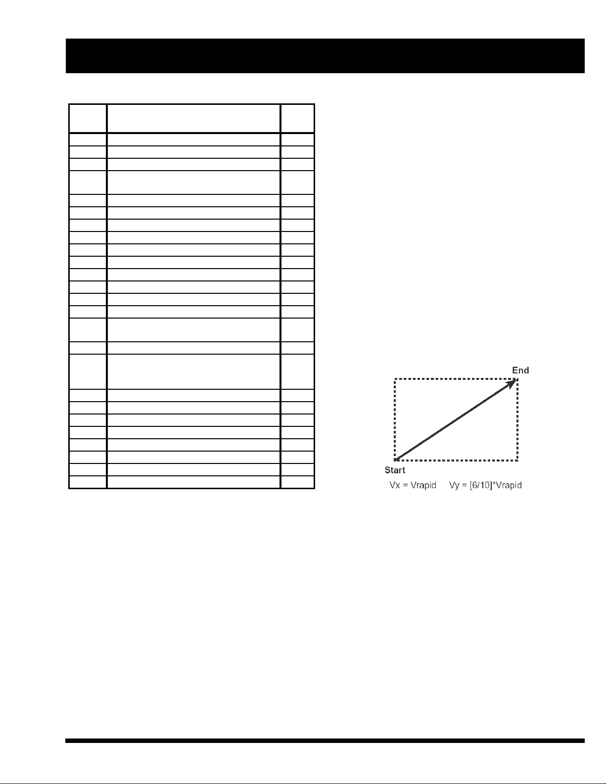
These four G-codes move the cutting nozzle to
commanded Work coordinates:
G00 Rapid Traverse move
G01 Linear move
G02 Clockwise Arc
G03 Counterclockwise Arc
These four G-codes form a modal group; the last G-code
moving the longer distance uses the rapid traverse rate of
the machine. The other axis moves at a lower velocity
proportional to the distance required, so both reach their
endpoints at the same time, approximating linear
interpolation.
If the command syntax is incorrect, a Message window
displays RAPID MOVE SYNTAX ERROR.
commanded in the group is active for all blocks until the
program commands another G-code in the group. The
default code when a program starts is G00. The leading
zero can be omitted; G0, G1, G2 and G3 are the same as
G00, G01, G02 and G03.
Each of these G-codes specifies the end of the move
with X and Y in the Work coordinate system. X and Y
1.01 G01 LINEAR MOVE
This command moves the cutting head to the work
coordinates (or incremental distance) defined by X and
Y, at a contouring feedrate optionally specified by F.
G01 X__ Y__ (F_)
are absolute coordinates when the program commands
EM-423 (R-02/11) 1-1
Page 8
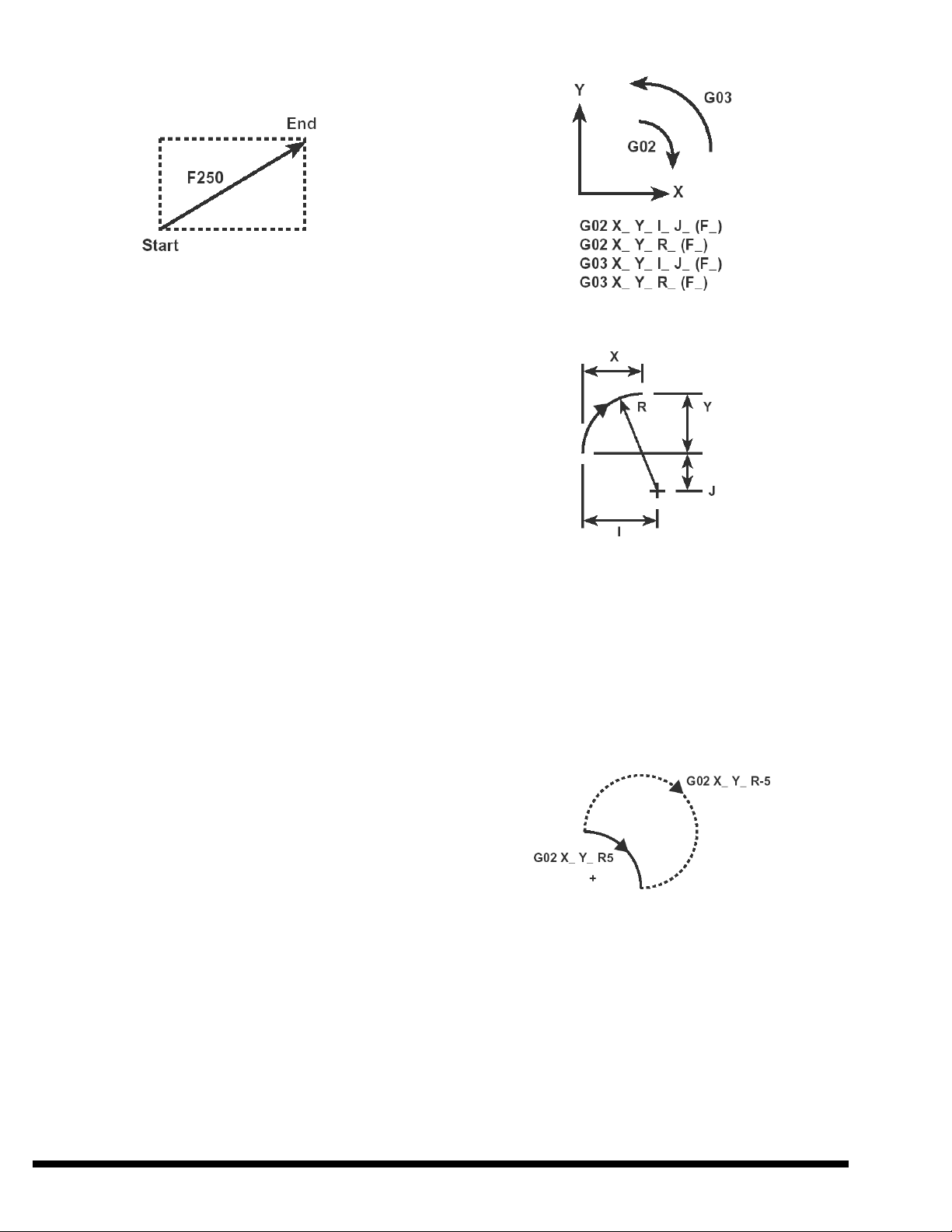
Example: (G91) G01 X6 Y4 F250
When the command requires both axes to change
position, the machine moves each axis at a velocity
required to produce a combined feedrate equal to the
contouring feedrate. The move follows the linear path
between start and end points.
If the command syntax is incorrect, a Message window
displays LINEAR MOVE SYNTAX ERROR.
FEEDRATE
The program can specify contouring feedrate from a
parameter library. For example, the program can
command F#148 after a block calling G89 Pfilename.lib.
The user can also configure the control to assign feedrate
to a different variable than #148 (see “Common
Variables”, SECTION 6).
1.02 G02 CLOCKWISE ARC
1.03 G03 COUNTERCLOCKWISE
ARC
A program uses G02 or G03 to command a circular
contouring move ending at the work coordinates (or
incremental distances) specified by X and Y. The
command defines the shape of the arc either by
specifying incremental distances (with I and J) from the
starting position to the center, or by specifying the radius
(with R). The control software interprets “I” and “J” as
distances in the X and Y directions (respectively) from
the starting position to the center. When the command
specifies radius “R”, the control moves the nozzle along
a circular path with that radius.
The machine maintains the modal contouring feedrate
(F) along the circular path.
Example: (G91) G02 X5 Y4 I7 J-3
When the block uses “R” instead of “I and J”, there are
two possible arcs for a given direction (cw or ccw) and
end coordinates. To specify which arc to contour, the
block commands “R” with a positive or negative sign.
To specify an arc that is less than 180 degrees, the block
commands a positive “R” value. To specify an arc
greater than 180 degrees, the G02 or G03 block
commands “R” with a negative value.
Example:
When G02 or G03 specifies the same coordinates for the
start and end of the arc, the machine contours a complete
circle. For complete circles, the block must specify the
center with I and J. Programming software must specify
both coordinates accurately. If the ending coordinates for
a circular move are not exactly the same as the starting
coordinates, the path may be a very small arc instead of
a complete circle. To avoid this problem, programs can
omit X and Y from a G02 or G03 block to command a
complete circle; the control will automatically apply the
same starting and ending coordinates.
1-2 EM-423 (R-02/11)
Page 9
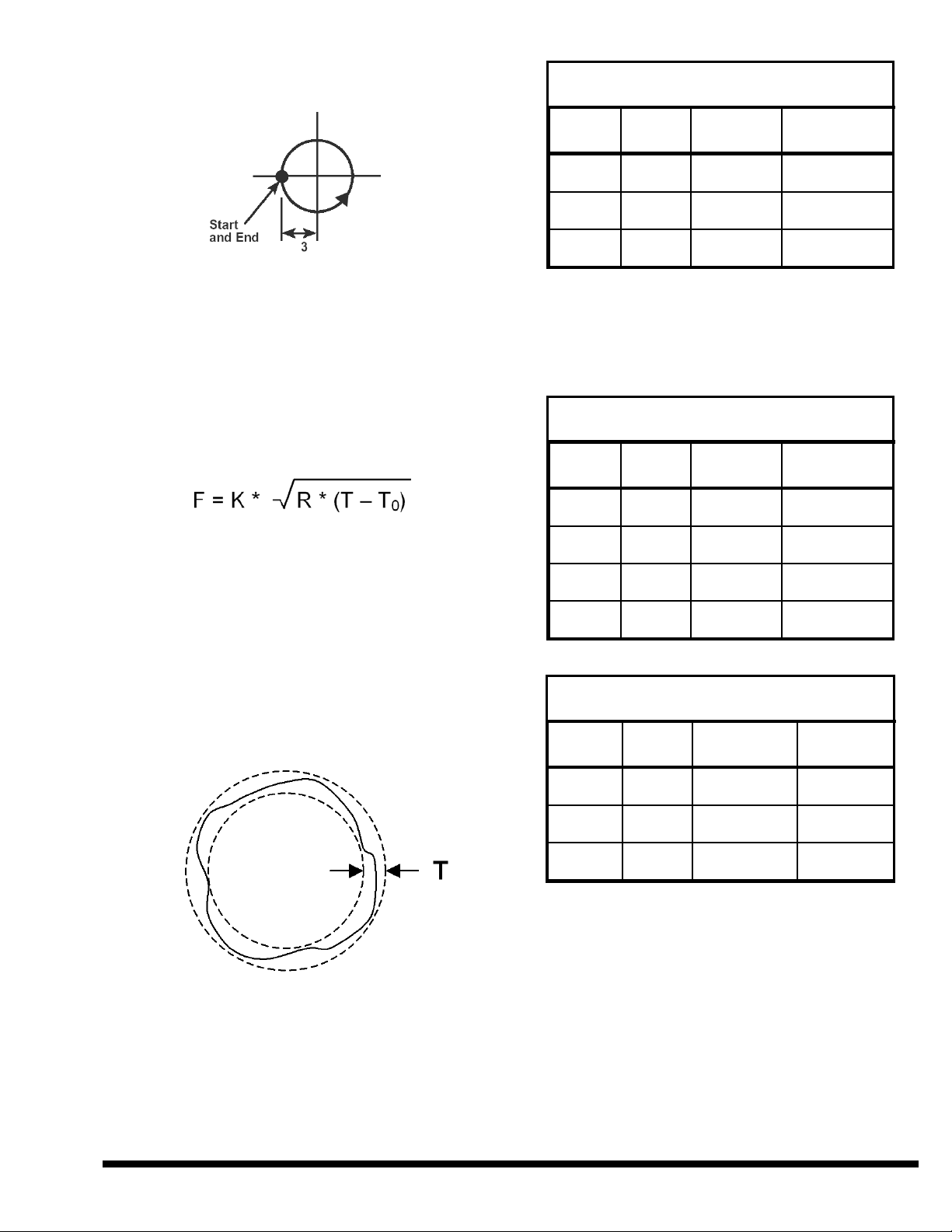
Example: (G91) G03 I3 J0
CL-707 Arc Feedrate Programming
(Original Drive Design)
Model K T0 Tmax
If the syntax is incorrect, the software will display the
CIRCULAR INTERPOLATION SYNTAX ERROR
message.
RECOMMENDED ARC FEEDRATE
Recommended maximum G02 or G03 feedrate depends
on machine design, arc radius, and allowable roundness
error. Use this equation to calculate the maximum
feedrate for each arc:
F = arc feedrate (IPM or mm/min.)
K = constant (1 / min.) See tables.
R = arc radius (inches or mm)
T = roundness tolerance (inches or mm)
T
= minimum radial error (inches or mm)
0
Roundness tolerance “T” is the radial distance between
two concentric circles that enclose the contoured shape.
To use this formula, the specified roundness tolerance
must be greater than “T
” and not more than “Tmax”.
0
4x8 18,000
5x10 18,000
6x12 18,000
.0002 in.
(.005 mm)
.0002 in.
(.005 mm)
.0002 in.
(.005 mm)
.006 in.
(.152 mm)
.006 in.
(.152 mm)
.005 in.
(.127 mm)
Arc feedrate programming parameters in the following
table apply to CL-707 laser systems with Serial
Numbers: 51226, 51242, 51296, 51466, 51509, 51553,
51572, 51631 and higher:
CL-707 Arc Feedrate Programming
(“Fast Pack” Drive Design)
Model K T0 Tmax
4x8 26,500
5x10 26,500
6x12 26,500
8x20 18,000
.0002 in.
(.005 mm)
.0002 in.
(.005 mm)
.0002 in.
(.005 mm)
.001 in.
(.025 mm)
.004 in.
(.102 mm)
.003 in.
(.076 mm)
.003 in.
(.076 mm)
.005 in.
(.127 mm)
CL-7A Arc Feedrate Programming
The maximum acceleration also determines the
maximum feedrate for contouring an arc. The following
tables include that requirement by specifying a
maximum roundness “Tmax” for each value of K. If the
roundness tolerance does not exceed Tmax, then the
calculated feedrate will not command the machine to
exceed the maximum acceleration.
EM-423 (R-02/11) 1-3
Model K T0 Tmax
4x8 6,000
5x10 6,000
6x12 6,000
.001 in.
(.025 mm)
.001 in.
(.025 mm)
.001 in.
(.025 mm)
.005 in.
(.127 mm)
.005 in.
(.127 mm)
.005 in.
(.127 mm)
To determine the feedrate for contouring an arc, compare
the calculated maximum feedrate to a minimum arc
feedrate (typically 30 IPM) and select the higher value.
Then compare the selected value to the material feedrate,
and use the lower value.
1.04 G04 DWELL
The G04 (or G4) command causes the CNC program to
dwell for the time specified by the P argument (in
milliseconds).
Page 10

Example (to dwell for one second):
G04 P1000
1.31 G31 POSITION CAPTURE
MOVE
This dwell time does not include the block processing
time of the CNC command.
If the software finds a syntax error, a message window
will display “DWELL SYNTAX ERROR”.
1.09 G09 EXACT STOP (ONE
BLOCK)
The program commands G09 (or G9) in the same block
as a G00, G01, G02 or G03 command. When the block
commands G09, the control does not proceed to the next
block until the axes reach zero feedrate. If the block does
not command G09, the control proceeds to the next
block when each axis position is within a specified
distance of the commanded position. The specified
distance is a system parameter.
Example: (G01 X_ Y_ ) G09
If the software finds a syntax error, a message window
will display “PROGRAMMING SYNTAX ERROR”.
1.20 G20 INCH MODE
1.21 G21 METRIC MODE
The G20 command puts the CNC in the inch units mode.
In G20 mode, the control interprets program coordinates
and feedrates in inch system units. (Positions are in
inches and feedrates are in inches per minute).
The G21 command puts the CNC in the metric units
mode. In G21 mode, the control interprets program
coordinates and feedrates in metric system units.
(Positions are in millimeters and feedrates are in
millimeters per minute).
When a program commands G31, the X and Y-axes
move to the specified coordinates in the Work
coordinate system. The G31 command uses the modal
contouring feedrate (F). While the axes are moving, the
control system monitors the Position Capture input. If
the control system receives the Position Capture input, it
records the X and Y-axis Machine coordinates at that
time and stores the values in system variables #5061 and
#5062.
G31 X_ Y_ (F_)
If the control detects more than one Position Capture
input during the move, it only saves the coordinates of
the first occurrence. If the control does not receive the
Position Capture input, it stores the coordinates at the
end of the move. The control always completes the move
to the coordinates specified in the G31 block (unless an
overtravel alarm stops motion).
Position Capture system variables:
#5061 = X axis Machine Coordinate
#5062 = Y axis Machine Coordinate
CINCINNATI macro programs use G31 to find
coordinates associated with optional measurement
functions (Workpiece Edge Detection or Optical Probe).
The machine control does not accept the G31 command
unless the machine configuration includes one of those
options.
1.40 G40 CANCEL KERF
COMPENSATION
1.41 G41 LEFT SIDE
COMPENSATION
The default mode is G20 when the CNC LASER
application starts. After the control runs a program, the
default mode is the same as the last program. To make
sure the control interprets a program correctly, the
program should begin by commanding G20 or G21 to
specify units.
G20 and G21 do not change the units mode of
CINCINNATI control windows. The windows display
values in inch or metric units as selected by the VIEW,
UNITS menu item.
1-4 EM-423 (R-02/11)
1.42 G42 RIGHT SIDE
COMPENSATION
G40 cancels G41 or G42. The cutting nozzle moves
from the compensated position to the commanded
coordinates during the G40 move.
Page 11

Example: G40
The CNC automatically commands the closest possible
position for the nozzle to contour the programmed shape
with the specified kerf size. If necessary, the control
inserts small moves so compensated paths intersect and
do not over-cut the shape.
Examples:
The control automatically cancels kerf compensation at
the end of any G00 or G53 move if the program
commands G00, G53, M02 or M30 in the next block.
If a program commands G40 in a block by itself, and
then commands a move without G41 or G42, the control
cancels compensation during that move.
A program commands kerf compensation with G41 or
G42. When a G01, G02 or G03 block commands G41 or
G42, the control begins that move with the nozzle offset
to one side of the programmed path. If a block
commands G41 or G42 without commanding a move,
the control ends the previous move with the cutting
nozzle offset to one side of the path.
Example: G41 and G42
1.50 G50 CANCEL SCALING
1.51 G51 WORK COORDINATE
SYSTEM SCALING
The CNC automatically offsets the cutting nozzle by half
the kerf width specified by last G89 command. (See
Section 2.89.)
G40, G41 and G42 form a modal group; the last G-code
commanded in the group is active for all blocks until the
program commands another code in the group. When
each program starts, the default code is G40.
EM-423 (R-02/11) 1-5
G51 X__ Y__ P__
G51 X__ Y__ I__ J__
The control interprets the work coordinate system at a
different scale or as a mirror image when the program
commands G51. The program can restore the normal
scale by commanding G50. When each program starts,
the default mode is G50. The Absolute Position window
and system variables indicate the actual position.
The G51 block defines the center of scaling with X and
Y, and the scale factor with “P”, “I” or “J”. To
command 1.0 scale (where the contoured shape is the
same as the programmed shape), the G51 block uses
P1000 (or I1000 or J1000). The G51 block can use I and
Page 12
J to command separate scale factors for the X and Y axes
(respectively). To contour a mirror image of the
programmed shape, the block commands I or J with a
negative value. The control does not scale the kerf
compensation offset distance when the program
commands scaling.
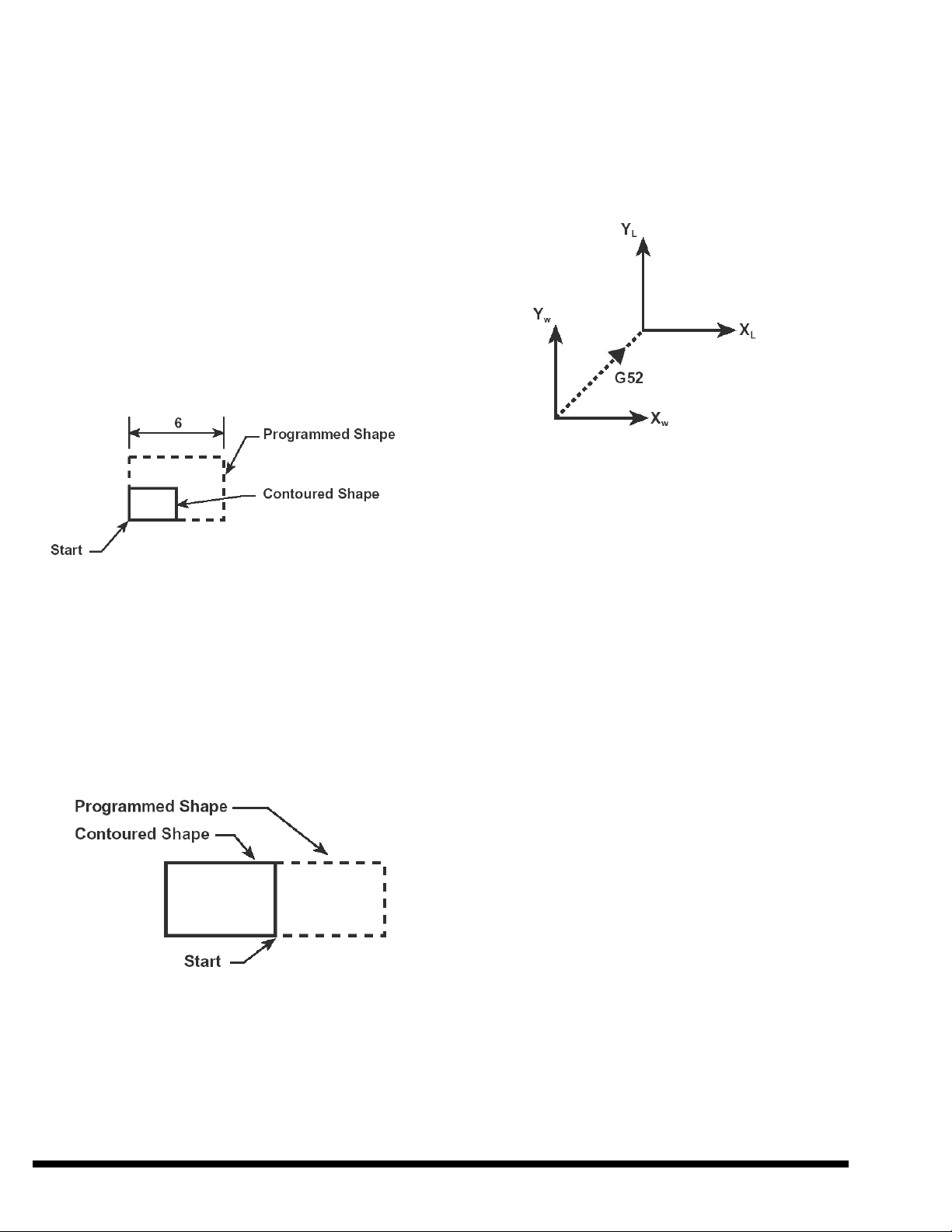
Example 1:
G91
G51 X0 Y0 P500
G01 X6
Y4
X-6
Y-4
G50
specified by X and Y in the G52 block. After the G52
block, the program makes contouring moves using the
new coordinate system. To restore the original work
coordinate system, the program commands “G52 X0
Y0”.
G52 X__ Y__
The G52 block does not move the cutting nozzle. The
Absolute Position window changes to indicate the nozzle
position in the temporary coordinate system.
Example 2:
G91
G51 X0 Y0 I-1000
G01 X6
Y4
X-6
Y-4
G50
To demonstrate how a program could use G52, consider
a program that uses a sub-program to contour the same
shape several times, and both the main program and subprogram use G90 (absolute) mode. The main program
would command a work coordinate system with G92 and
the sub-program would command a local coordinate
system with G52, then cancel it with G52 X0 Y0.
1.53 G53 RAPID MOVE TO MACHINE
COORDINATES
G53 X_ Y_
The G53 command moves the cutting nozzle at the rapid
traverse rate to a position specified by X and Y in the
machine coordinate system. G53 is only active in one
block and only in G90 absolute mode. No motion occurs
if the program commands G53 in G91 (incremental)
mode. The control does not change the machine
coordinate system when the program commands kerf
compensation, rotation, scaling, or mirror image, or if
the program changes the work coordinate system.
1.52 G52 LOCAL WORK
COORDINATE SYSTEM
The G52 command temporarily defines a new work
coordinate system while remembering the original. The
zero position of the new (or “local”) coordinate system
is at the coordinates in the original coordinate system
1-6 EM-423 (R-02/11)
1.54 G54 THROUGH G59
WORK COORDINATE SYSTEM SELECTION
A program can use G54 through G59 to command one of
six different pre-defined work coordinate systems. The
user can set the distance from Machine X0 Y0 to the
Work X0 Y0 position of each coordinate system with the
Page 13

“Position, Work Offset” window, or the program can
assign the distance with system variables #2501 through
#2506 (X) and #2601 through #2606 (Y).
G54 (OFFSET 1)
G55 (OFFSET 2)
G56 (OFFSET 3)
G57 (OFFSET 4)
G58 (OFFSET 5)
G59 (OFFSET 6)
program is in a separate file then the G65 block must
command “P” followed by the sub-program filename
including its extension (if any) and its path if different
from the calling program.
If the G65 command includes arguments, the command
must have a space between the last character of the
program name and the first argument. This is required
because program names can contain both numerals and
alphabetic characters.
A work coordinate system defined with G54 through
G59 does not need G92 to define its X0 Y0 position.
G54 through G59 override G92 by commanding a work
coordinate system with its X0 Y0 position preset on the
machine.
The G54 through G59 block does not move the cutting
nozzle. The absolute position window changes to
indicate the nozzle position in the new work coordinate
system.
If the block contains a syntax error, the control will
display the message “WORK COORDINATE SYNTAX
ERROR”.
1.61 G61 EXACT STOP MODE
1.64 G64 CANCEL EXACT STOP
MODE
G61 commands the CNC to use exact stop mode. In this
mode, the axes decelerate to a stop at the end of every
G00, G01, G02 or G03 block. The CNC remains in G61
mode until the program commands G64 or the program
ends.
The G64 command cancels exact stop mode. The default
mode when each program starts is G64. In G64 mode,
the control proceeds to the next block when each axis
position is within a specified distance of the commanded
position. The specified distance is a system parameter.
1.65 G65 SUB-PROGRAM CALL
(WITH OPTIONAL ARGUMENTS)
The G65 block specifies the sub-program name after
“P”, and may use other arguments to set local variables
in the subprogram.
Note: Revised CNC software (installed July 2001 or
later) does not require a space between the
program number and the first argument if a G65
command specifies P9800 or P9900.
For instructions on calling sub-programs with G65, see
SECTION 5. If the G65 block contains a syntax error,
the control displays the message “G65 SYNTAX
ERROR”.
1.68 G68 WORK COORDINATE
SYSTEM ROTATION
1.69 G69 CANCEL ROTATION
A program can use the G68 command to rotate the work
coordinate system relative to the machine axes. The
command specifies the center of rotation with X and Y
work coordinates (or incremental distances). The
command specifies the amount of rotation with “R” in
degrees, with counterclockwise positive. In G90 mode,
R is the absolute angle of rotation. In G91 mode, R is the
incremental rotation angle that the control adds to any
previous rotation.
G68 X_ Y_ R_
The work coordinate system remains rotated until the
program commands G69 or the program is reset. G69
cancels all coordinate rotation. To cancel only the last
incremental rotation, command G68 in G91 mode with
the opposite amount for “R”.
The G68 or G69 block does not move the cutting nozzle.
The Absolute Position window and System Variables
indicate the nozzle position in the un-rotated work
coordinate system.
G65 P_ (A_ B_ C_ D_ etc. )
The G65 block must include “P” followed by the name
of the sub-program. If the sub-program is in the same
file as the CNC program, then the sub-program name
does not need an extension or path. However, if the sub-
EM-423 (R-02/11) 1-7
Page 14
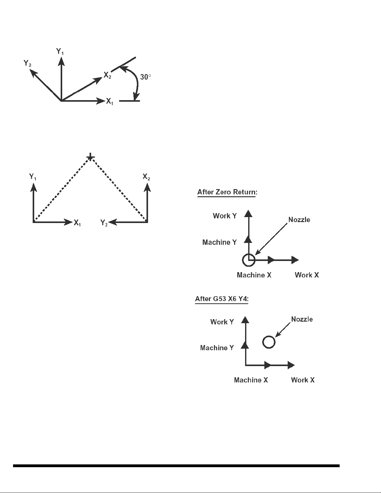
Example 1: G68 X0 Y0 R30
X0 Y0 at Machine X0, Y0. The G92 command can
move the work coordinate system to any location.
G92 X_ Y_
X and Y define the new work coordinates corresponding
to the cutting nozzle position when the G92 block is
executed.
The G92 block does not move the cutting nozzle. The
Absolute Position window changes to indicate the nozzle
position in the new work coordinate system.
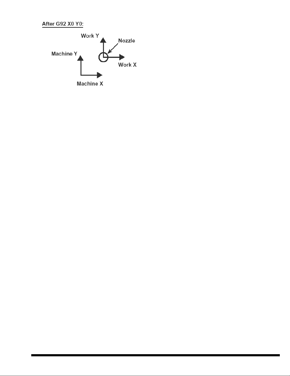
Example: G92 X0 Y0
Example 2: G68 X5 Y5 R90
1.90 G90 ABSOLUTE MODE
1.91 G91 INCREMENTAL MODE
In G90 absolute mode, the nozzle moves to the
coordinate location specified by the arguments in a G00,
G01, G02, G03 or G53 command. G90 mode is active
until the program commands G91 mode. When each
program starts, the default mode is G90.
The G92 X0 Y0 command moves the work coordinate
system X0 Y0 location to the current position of the
cutting nozzle. Programmers often use this command to
begin a sub-program written in G90 mode.
G92 Example:
In G90 mode, X and Y coordinate values are modal. In
other words, if a block does not specify X or Y, the
control uses the last commanded value for X or Y.
In G91 incremental mode, the cutting nozzle moves a
distance from its starting location specified by X and Y
in a G00, G01, G02 or G03 command. G91 mode is
active until the program commands G90 or the program
ends. The control ignores a G53 command while
operating in G91 mode.
1.92 G92 WORK COORDINATE
SYSTEM SETTING
This command sets the work coordinate system location.
When the machine completes the Axes Home operation,
the control establishes the work coordinate system with
1-8 EM-423 (R-02/11)
Page 15
EM-423 (R-02/11) 1-9
Page 16

1-10 EM-423 (R-02/11)
Page 17
SECTION 2 CUSTOM G-CODES
The CINCINNATI control has built-in functions
programmed with custom G-Codes.
CODE DESCRIPTION SEC.
G84 Pierce and Start Cut 2.84
G85 Start Cut without Pierce 2.85
G89 Process Parameters 2.89
G102 Additional Parameters 2.102
G103 Ramped Pierce Parameters 2.103
G120 Disable Non-Stop Cutting 2.120
G121 Enable Non-Stop Cutting 2.121
G123 Programmable Blend 2.123
G124 Default Blend 2.124
G125 Auto Blend 2.125
2.84 G84 PIERCE AND START CUT
2.85 G85 START CUT WITHOUT
PIERCE
A program uses G84 or G85 to begin user-programmed
cutting sequences. G84 and G85 command the Z-axis to
move the nozzle down to the standoff position (if not
already there), and then command the pierce and/or cut
parameters. When the control finishes the G84 or G85
command, it returns to the program with the laser beam
on, assist gas on, and shutter open, ready to proceed with
contouring commands (G01, G02, G03). G84 and G85
also turn coolant on if the process parameters specify
coolant.
A program uses G85 to begin a cut sequence when the
application does not require the pierce cycle of G84.
G85 duplicates all other functions of G84, including
precut dwell and power burst time (see G102
description). After a program commands processing
parameters with G89, any cut sequence can start with
G84 or G85. Examples of G85 applications are: starting
a cut inside an opening, off the edge of the sheet, or in a
kerf.
AUTO RESTART
Tracing Function Forward or Reverse button to move in
the forward or reverse direction to another program
block. De-select Tracing mode and then press Cycle
Start to resume the cut. If an alarm condition interrupts
a program and the operator presses Cycle Start without
selecting Tracing mode, the cutting nozzle moves to the
start of the interrupted block and resumes cutting.
PIERCE OPTIONS (G84 T_)
Each process parameter library file has one set of cutting
parameters and three pierce options. The G84 “T”
argument selects the pierce option for each cutting path.
Normal Pierce G84 or G84 T1:
G84 T1 is the same command as G84. The program
commands normal pierce parameters with a G89 library
file, or explicitly with G89, G102 and G103 macro calls.
Rapid Pierce G84 T2:
The program commands G84 T2 to use rapid pierce.
Rapid pierce has separate laser power, gas pressure,
dwell time and standoff parameters. Laser pulse mode is
always 5000 Hz and 100% duty cycle. G84 T2 uses the
same assist gas (#1 or #2) and part coolant status as
normal pierce.
Rapid pierce uses a single power level during the pierce,
so ramped pierce is always OFF. Rapid pierce also has a
cooling time parameter independent from G84 T1 and
airblast time parameters.
G89 loads rapid pierce parameters from a library file.
The NC program cannot set rapid pierce parameters
explicitly with G89, G102 or G103. When the program
commands normal pierce parameters explicitly, the
default T2 parameters are the same as T1.
G84 T3:
G84 T3 operates the same as G85 (no pierce).
Note: All G84 pierce options (T1, T2 or T3) command
pre-cut dwell before returning to the program.
For a description of pre-cut dwell, see G102 in
this section.
When a laser system has the CINCINNATI control, the
CNC program does not require special codes or
commands to activate Auto Restart. When an alarm
condition interrupts a program, the operator can restart
the program at any block. After correcting the condition
that caused the interruption, the operator can select
Tracing mode, press Cycle Start, then hold down the
EM-423 (R-02/11) 2-1
AIRBLAST
The rapid pierce process uses a separate blast of
compressed air to help clear molten material from the
pierce area. Two airblast parameters (“OFF time” and
“ON time”) control the opening of the airblast solenoid
valve.
Page 18
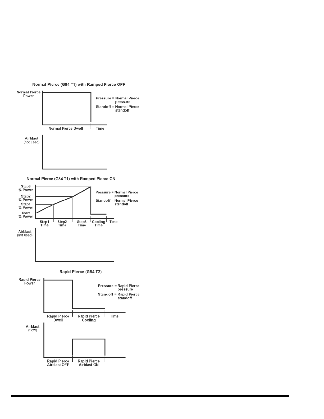
The OFF time is a delay that starts when the pierce
begins. The air valve is closed during the OFF time.
When the delay ends, the air solenoid valve opens. The
valve then stays open for the ON time. To edit the
airblast times, open the Process Library Window.
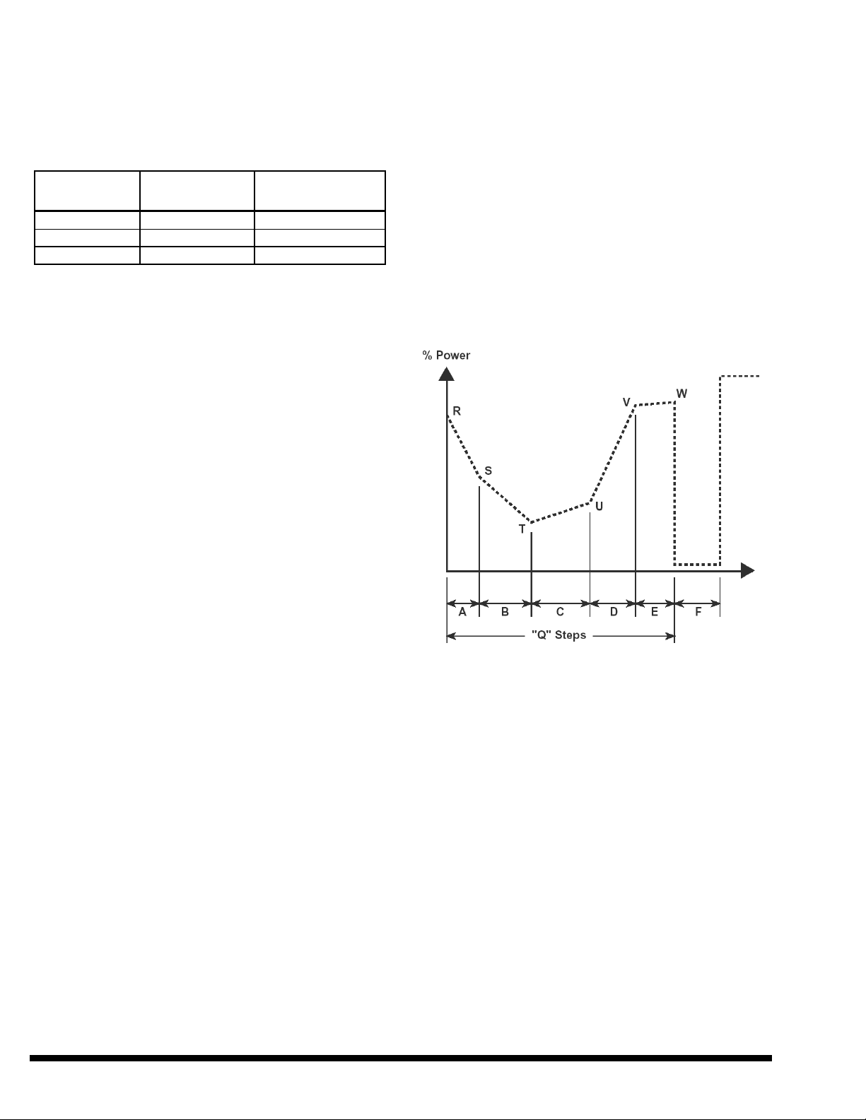
The following figures show the function of G84 T1 and
T2 parameters:
2.89 G89 PROCESS PARAMETERS
The program sets processing parameters by commanding
G89. When G89 loads processing parameters with a
library file, the operator can edit the parameters while
the program is running; however, changes will NOT take
effect until the next G84 (or G85). To change
parameters, open the library file, edit the parameter(s)
then save the library file.
The CINCINNATI control will also accept G89, G102
and G103 commands programmed with explicit
parameters.
G89 WITH LIBRARY FILE
G89 Pfilename.lib
The G89 command uses address “P” to specify a library
file. The operator can edit library files in the Process
Parameter window. The default path is:
D:\CNCLSR32\MATERIAL\
The filename must include the “.lib” extension.
If the library file is not in the MATERIAL folder, the
G89 command must include the path. The user can
create other library directories, in either the MATERIAL
folder or elsewhere on the disk.
CINCINNATI INCORPORATED provides a set of
read-only library files in this folder:
“D:\CNCLSR32\MATERIAL\ARCHIVE\”
The MATERIAL directory includes copies of the same
library files, which the user can edit.
Library filenames provided by CINCINNATI
INCORPORATED begin with an abbreviation for
material:
AL . . . Aluminum
MS . . . Mild Steel
SS . . . Stainless Steel
After the material abbreviation, the library filename has
a three-digit number representing the material thickness
in mils.
Example: (For 10 gauge mild steel 0.135”): MS135
The filename may include other characters after the
thickness number, to indicate a resonator type or
processing application.
After the thickness number, the filename may have a
chemical abbreviation for the cutting assist gas:
2-2 EM-423 (R-02/11)
Page 19
O2 . . . Oxygen
N2 . . . Nitrogen
For applications using coolant, the library filename ends
with the word “wet”.
Examples: (10 gauge mild steel, oxygen cut)
Without coolant: MS135O2.lib
With coolant: MS135O2wet.lib
When pulsed laser output is used, frequency and
duty cycle are specified with a 4-digit code in which
the first two digits specify frequency (Hz/100) and
the last two digits specify duty cycle (%).
For DC (diffusion-cooled) resonator, maximum
frequency is 5000 Hz and minimum duty cycle is the
value necessary for a pulse ON time of 26
microseconds at the commanded frequency.
G89 CALL WITH ARGUMENTS:
G89 T_ A_ I_ M_ S_ C_ D_ Q_ B_ E_ H_ R_ J_
K_ U_ V_
T = Cut power level, watts.
A = Cut gas code. See Note 1.
I = Cut gas pressure. See Note 2.
M = Cut laser mode, see Note 3.
S = Cut pulse code, see Note 4.
C = Cut coolant code. See Note 5.
D = Pierce time, seconds.
Q = Pierce power level, watts.
B = Pierce gas code. See Note 1.
E = Pierce gas pressure. See Note 2.
H = Pierce laser mode, see Note 3.
R = Pierce pulse code, see Note 4.
J = Pierce coolant code. See Note 5.
K = Kerf width, see Note 2.
U = Maximum feedrate for Dynamic Power, see Note 2.
V = Minimum percent for Dynamic Power (% at zero
feedrate)
Notes:
1. Assist gas codes (A & B):
11 = Gas Port #1 (usually O2)
12 = Gas Port #2 (usually N2)
2. G89 interprets pressures, kerf width, and dynamic
power feedrate in the active units:
Parameter G20 unit G21 unit
I & E PSI kPa
K inches mm
U IPM mm/min
5. Coolant codes (C & J):
8 = coolant ON
9 = coolant OFF
When CINCINNATI laser systems with Fanuc control
have the Macro Executor option, programs written for
those laser systems can specify process parameters with
G89 X_, where X is followed by a library code number
from 1 to 100. The CINCINNATI control will accept a
program with the “G89 X” command (instead of G89 P),
if the Material folder has a library file with the same
name as the number following “X”. For example, the
CINCINNATI control will accept a program
commanding “G89 X32” if the Material folder has a
library file named “32.lib”.
When a program commands G89, G102 or G103 with
explicit parameters, the CINCINNATI control checks
the parameters for out-of-range values. If the control
finds any, it displays an error message in a pop-up
window indicating which parameter has the error. The
window identifies parameters by the name used in the
Process Parameter Library window, not by the G89,
G102 or G103 argument. For example, “Pierce Gas
Pressure out-of-range” instead of “G89 E out-of-range”.
2.102 G102 ADDITIONAL
PARAMETER SETTINGS
The Parameter Library window includes settings for
dynamic gas pressure, noncontact standoff, optional
pressure, precut dwell and power burst time. In addition
to commanding these parameters in a library file with
G89, the program can also command these parameters
explicitly with G102.
G102 A_ B_ S_ Z_ D_ I_ T_ Q_ R_ U_ V_
3. Laser mode (M & H):
61 = Continuous Wave
62 = Gated Pulse
66 = Dynamic Power
4. Pulse codes (S and R):
EM-423 (R-02/11) 2-3
A = Dynamic gas pressure near field setting
B = Dynamic gas pressure far field setting
S = Pierce standoff
Z = Cut standoff
D = Precut dwell, seconds
I = Optional pressure
T = Power burst time, seconds
Q = Pierce Focus, Near Field
Page 20
R = Pierce Focus, Far Field
U = Cut Focus, Near Field
V = Cut Focus, Far Field
G102 interprets pressure, standoff and focus settings in
the active units:
Parameters G20 unit G21 unit
A, B & I PSI kPa
S & Z inches mm
Q, R, U & V inches mm
A & B: When a program commands dynamic gas
pressure, the control regulates cutting assist gas
pressure between the Near (A) and Far (B) field
settings based on the machine position of the nozzle.
Near field is where the laser beam length is shortest.
S & Z: The program uses these settings to command
pierce and cut nozzle standoff distance for the
noncontact head.
G103 A_ B_ C_ D_ E_ F_ Q_ R_ S_ T_ U_ V_ W_
A = Ramp 1 duration, seconds
B = Ramp 2 duration, seconds
C = Ramp 3 duration, seconds
D = Ramp 4 duration, seconds
E = Ramp 5 duration, seconds
F = Tip cooling time, seconds
Q = Number of ramp steps (1 to 5)
R = Percent power at start of first ramp
S = Percent power at start of second ramp
T = Percent power at start of third ramp
U = Percent power at start of fourth ramp
V = Percent power at start of fifth ramp
W = Percent power at end of fifth ramp
D: Before returning to the program, G84 and G85
command the cutting parameters and then command
the pre-cut dwell.
I: The assist gas pressure controller uses the optional
pressure setting when a program commands M67.
T: When the laser system starts a contouring move using
dynamic power, the control maintains dynamic power
at 100% for the time specified for Power Burst. After
the Power Burst time, the control regulates dynamic
power according to the actual feedrate.
Q, R, U and V: When CL-707 lasers or CL-7A lasers
with CINCINNATI control have the Auto Focus
Cutting Head option, the G102 command has
additional arguments to specify focus settings. The
settings specify focus position relative to the nozzle
tip. The Auto Focus drive uses the Near field settings
when the cutting head is closest to the laser source,
and changes focus between the Near and Far settings
as X and Y-axis motion changes the optical path
length. Q and R specify the Near and Far field pierce
focus settings. U and V specify the Near and Far
field cut focus settings.
2.103 G103 RAMPED PIERCE
SETTINGS
To set parameters for ramped pierce power, the CNC
program can either command G89 with a library file, or
command G103 with explicit settings.
G103 Ramped Pierce Arguments
2.120 G120 DISABLE NON-STOP
CUTTING
2.121 G121 ENABLE NON-STOP
CUTTING
When a program commands Non-Stop Cutting (G121),
the CNC replaces short G00 moves between cut
sequences with “Smart Rapid” moves. A Smart Rapid
move commands the laser beam off and on without
stopping the axes. (See Smart Rapids description below.)
During a Smart Rapid move, the control maintains assist
gas flow, even when the laser beam is off.
Notes: A program can only command Non-Stop cutting
mode when the process parameters specify no
pierce time and no precut dwell.
2-4 EM-423 (R-02/11)
Page 21

If the operator edits and saves process
parameters while running a program in Non-
program should not command G00. The control will not
replace G01 G02 or G03 moves with Smart Rapids.
Stop mode, the CNC ignores the changes until
the program ends.
Notes: In this description, G85 can replace G84.
The G120 command cancels Non-Stop cutting mode.
When each program starts, the default mode is G120.
SMART RAPIDS
Programming software normally commands a single
G00 linear rapid move between the end of one cut
sequence and the beginning of the next. The G00 move
commands the shortest distance between the two points
(to minimize the time between cuts). However, in the
default mode (G120), the nozzle must stop before and
after the G00 move (to turn the beam off and on). In
Non-Stop cutting mode (G121), the nozzle does not stop
to turn the beam off or on.
When the operator loads a program, the control
translates the program into commands for the CNC to
execute. If the program specifies G121 mode, the control
translates G00 moves into “Smart Rapid” moves. The
control replaces the G00 move and the contouring moves
before and after it with commands that maintain the
original beam-on path without stopping the axes.
The CINCINNATI software performs these tasks to
create a Smart Rapid:
When the move before M35 or after G84 is an
arc, the control inserts a Smart Rapid G01 move
tangent to the arc at the intersection point.
BEAM ON / OFF TIMING
The laser system can turn the beam on and off at a
desired time within 3 to 5 milliseconds. This means that
the cut actually starts or stops within a distance
representing 3 to 5 milliseconds of travel on either side
of the desired point.
Example:
At 300 inches/min., the length of the tolerance band
could be (300 in./min.) / (60 sec./min.) * .005 sec. = ±
.025 inches (0.63 mm)
The size of the tolerance band depends on the control
design. In the original control design, the tolerance is ±
5 milliseconds. For laser systems with the “Fast Pack”
control design, the tolerance is ± 3 milliseconds.
CUT EXTENSION
The CNC determines the G121 extension time to control
how the laser system cuts shapes in G121 mode.
1. Command M35.
2. Command a G01 move after M35 at the same
feedrate and direction as the move before M35.
3. Command a G01 move at high feedrate between the
G01 moves inserted in Steps 2 and 4.
4. Command a G01 move before G84 at the same
feedrate and direction as the move after G84.
5. Command G84.
6. Lengthen the move after G84.
Although the CNC uses a “linear” G01 connecting move
(instead of G00), the high G01 feedrate produces a
curved path as the axes blend with the other G01 moves.
The result is a smooth non-stop transition between cuts.
If the original program has anything other than a single
G00 move between cuts (between M35 and G84), the
control does not create a Smart Rapid.
During a Smart Rapid move, the nozzle may deviate
from the original programmed path while the beam is
off. If the nozzle must follow the original path, then the
Consider a round hole with a radial lead-in. In
conventional cutting, the programmer might end the
lead-in with exact stop (G09). However, a lead-in
programmed for Non-Stop mode may not command
exact stop, and the end of the lead-in would blend into
the start of the circular move. Also, beam On/Off
positions are not as precise when using Smart Rapids (as
described above). Thus, the slug from a 360-degree
circular hole may not drop because the beam would not
cut the entire perimeter of the hole (see figure below).
Extending the circular move assures that the beam will
cut the entire shape.
EM-423 (R-02/11) 2-5
Page 22

It is important to place the lead-in so the extension of its
last entity will meet or overlap the beginning of the first
contoured entity. If the program commands a lead-in at a
corner, the extension of the last entity will cut past the
desired perimeter of the feature, as shown in the
following diagram.
EFFICIENCY
As described above, the path of a Smart Rapid is not a
straight line. The ends are smoothed, the way a baseball
player rounds the base paths on an extra base hit.
Program efficiency is greatest when the path length is
shorter. Path length between two features depends on
cutting direction and placement of lead-ins, as shown in
the following diagram.
2.123 G123 PROGRAMMABLE
BLEND
2.124 G124 DEFAULT BLEND
2.125 G125 AUTO BLEND
The process of ending one contouring move and
beginning the next move usually requires changing the
velocity of one or both axes. In this manual, this process
is called a “blend”.
The objective of a blend is to change the axis from
executing the preceding move at its constant velocity to
executing the next move at a different constant velocity.
To accomplish this transition, acceleration also changes
during the blend. When velocity is constant, acceleration
is zero. Therefore, during a blend (between linear moves,
for example), acceleration begins at zero, increases or
decreases to produce the velocity change, then returns to
zero to complete the blend.
The CINCINNATI control executes a blend using two
parameters: the overall time to complete the velocity
change and the portion of that time which is used to
change the acceleration. Just as a motion system has a
maximum velocity and a maximum acceleration, it is
also limited by how quickly it can change acceleration.
The cases shown in the figure have two programming
differences: the cutting direction of the left hole, and the
location of the lead-in on the right hole. Note the “Uturns” required in the top path.
When selecting lead-in locations, the desire to minimize
Smart Rapid path length may conflict with the desire to
maximize “head down” operation (by avoiding tipped
slugs). The conflicting requirements often require some
compromise.
Short blend times improve contouring accuracy and
increase productivity by using high acceleration, but can
produce servo following errors if the machine attempts
to exceed its acceleration capability. Long blend times
avoid servo following errors but sacrifice contouring
accuracy. Since blend time settings can affect processing
results, users can program blend times with three
different commands:
G123 specifies fixed time values for all blends:
G123 A_ S_
A = Total blend time, in milliseconds
S = Time for acceleration change, in milliseconds
The minimum value of “A” is S * 2.
2-6 EM-423 (R-02/11)
Page 23

G124 commands the control to use a set of default times
for all blends. The default time values are set by
CINCINNATI INCORPORATED.
G125 Auto Blend enables the control to determine the
minimum X and Y blend times independently for each
move.
When each program starts, the default mode is G125.
Different parts of a program can use different blend
control modes. A program can change from G123, G124
or G125 to either of the other modes.
If either G123 or G124 setting is less than a minimum
time, the control uses the minimum time without
displaying an error message. The control determines the
minimum blend time for each move using parameters set
by CINCINNATI INCORPORATED.
EM-423 (R-02/11) 2-7
Page 24

2-8 EM-423 (R-02/11)
Page 25

SECTION 3 M-CODES
Most M-codes command machine functions not directly
related to CNC operation. If an M-code block does not
have the proper syntax, program execution stops and a
message window displays the message “INVALID MCODE”.
has selected the Optional Stop button on the CNC
control window. The program resumes when the
operator presses CYCLE START.
3.02 M02 END OF PROGRAM
CODE DESCRIPTION SEC.
M00 Cycle Stop 3.00
M01 Optional Stop 3.01
M02 Program End (No Rewind) 3.02
M30 Program End (and Rewind) 3.30
M35 Beam Off 3.35
M36 Noncontact Z-Axis Servo Hold 3.36
M37 Beam Off, Gas Off, Shutter Close 3.37
M38 Timed Z-Axis Servo Hold 3.38
M41 Lower Z –Axis 3.41
M42 Retract (Raise) Z Axis 3.42
M43 Enable Lower Pallet Special
Function
M44 Disable Lower Pallet Special
Function
M45 Apply Optional Standoff 3.45
M47 Raise Z-Axis, optionally by
distance
M48 Disable Feedrate Override 3.48
M49 Enable Feedrate Override 3.49
M50 Switch Pallets 3.50
M51 Enable Timed Auxiliary Output 3.51
M67 Apply Optional Gas Pressure 3.67
M98 Call Sub-program 3.98
M99 Return from Sub-program 3.99
M130 Disable Anti-dive 3.130
M131 Enable Anti-dive 3.131
M135 Beam Off with Gas On 3.135
3.43
3.44
3.47
3.00 M00 PROGRAM STOP
When the CNC executes a program block commanding
M00 (or M0), the program stops until the operator
presses CYCLE START. If the laser beam and assist gas
were on, the M00 command turns them off. M00 places
the CNC in a Cycle Stop condition. Modal information
does not change.
3.01 M01 OPTIONAL STOP
The M01 (or M1) command has the same function as the
M00 command, except M01 is only active if the operator
A CNC program can use M02 (or M2) as the last block.
This function disables all processing functions, resets all
previously requested M-codes and prevents further
execution. The program does not rewind automatically.
When the operator loads a program into the CNC, the
control ignores any codes following M02.
3.30 M30 END OF PROGRAM WITH
REWIND
Most CNC main programs use M30 as the last block.
This function disables all processing functions, resets the
CNC, cancels all previously requested M-codes,
prevents further execution and rewinds the program.
3.35 M35 BEAM OFF
M35 turns the laser beam OFF at the end of a cut
sequence. Laser discharge current stops. Assist gas flow
also stops, unless the SPEED GAS option in the
Variables menu is selected (see M135). Discharge
current remains OFF until the next G84 or G85.
3.36 M36 SERVO HOLD FOR
NONCONTACT Z-AXIS
The M36 command places the Z-axis control for the
Non-contact head in a servo hold condition when the
nozzle is in the cutting position and the laser beam is
ON. The noncontact head does not follow the material
after the program commands M36. To clear M36, the
program commands M35, M37, M42, M47 or M30, or
the operator presses RESET.
3.37 M37 BEAM OFF, GAS OFF AND
SHUTTER CLOSE
M37 turns off the laser beam and assist gas and
commands the shutter to close. M37 also resets any
previously requested M-codes.
To avoid unnecessary cycling of the gas valves and
shutter, most programs use M35 instead of M37. The
EM-423 (R-02/11) 3-1
Page 26

control accepts M37 to support programs written for
laser systems without M35.
3.38 M38 TIMED NONCONTACT
SERVO HOLD
M38 places the Z-axis control for the Noncontact head
in a servo hold condition for a period of time after the
control establishes the cutting position. The M38 block
specifies the time with the P argument (in milliseconds).
Example:
M38 P2000
(This example commands the Z-axis to maintain a
fixed position for 2 seconds after reaching the nozzle
standoff position.)
To start the M38 time, the Z-axis must be in the cutting
position with the beam on, and the X or Y axis must be
moving. The Z-axis maintains position until the time has
elapsed. After the specified time, the Z-axis goes into
tracking mode.
The program can command M38 before or after G84. To
cancel M38, the program commands M36, M42, M47 or
M30, or the operator presses RESET.
3.41 M41 COMMAND Z-AXIS DOWN
TO CUT POSITION
systems equipped with the Lower Pallet Special
Function option, users can extend the allowable beam-on
range to 7.0 inches (178mm) on the lower pallet by
commanding M43.
The M43 operating mode allows the machine to process
square or rectangular tubing or other formed parts on the
lower pallet. Operation above 1.5 inches (38mm) is not
possible on the upper pallet because the Z-axis reaches
its upper limit.
M43 changes these control functions:
1. The Z-axis travels down from the top position at a
lower speed to find the material surface.
2. The pallets cannot be moved with M50 or with
pallet JOG buttons.
3. The Y-axis cannot exceed the machine coordinate
specified on the CONFIGURATION window for
this option.
M43 disables pallet motion because material over 1 inch
(25mm) high will not clear the upper pallet. Since the
pallets cannot move and the X-axis beam delivery blocks
access to the pallet from one side of the main frame, the
operator must load and unload the pallet from the other
side of the main frame (the operator side). To keep
material within reach of the operator side, the control
does not allow the Y-axis to exceed the machine position
set on the CONFIGURATION screen.
M41 commands the Z-axis to move the cutting nozzle
down to the commanded standoff position. Programs
normally do not use M41 because G84 and G85 include
that function. M41 allows a program to command the
cutting nozzle down to the material without starting a
cut.
If the cutting head does not find material, the Z-axis
travels down until it reaches a minimum position or
exceeds a time limit, causing motion to stop.
3.42 M42 RETRACT Z-AXIS
M42 commands the Z-axis to the full up position. The
shutter is commanded to close. Programs use M42 to
command the Z-axis to the required position for pallet
motion.
3.43 M43 LOWER PALLET SPECIAL
FUNCTION
In normal operation, the control only allows the beam on
when the cutting nozzle is within 1.5 inches (38mm) of
the material support height on either pallet. On laser
Recommended procedure to use M43:
1. Move the upper pallet OUT and the lower pallet
IN.
2. Jog the nozzle to Machine Y0.
3. Load and execute a program with only M43 and
M30. (CINCINNATI provides such a program
named “M43.cnc”.)
4. Verify M43 mode is active (FYI Message).
5. Load material on the lower pallet.
6. Load the CNC program for the loaded material.
Programs using M43 mode can begin with M43, but to
avoid accidental damage, do not load material over 1
inch (25mm) high until M43 mode is already active. The
control will execute the M43 command with Program
Test on or off.
3-2 EM-423 (R-02/11)
Page 27

When a laser system has this option, the CNC is in M43
mode each time the operator turns on the machine
control. M43 mode is NOT cancelled by M30, RESET
or turning off the control. The only way to cancel M43
mode is to run a program commanding M44.
3.44 M44 CANCEL LOWER PALLET
SPECIAL FUNCTION
3.47 M47 RAISE Z-AXIS,
OPTIONALLY BY DISTANCE
M47 commands the Z-axis to raise a fixed distance, or a
programmed distance if the command specifies a value
with “P”. The Z-axis Maintenance Configuration
window displays the fixed M47 distance as “Default
Partial Z-Up Distance (M47)”.
The M47 command can specify a programmed distance
with “P”. The distance units are thousandths of an inch
for G20 mode and thousandths of a millimeter in G21
mode. Maximum command is M47 P3000 for 3 inches
or M47 P76200 for 76.2 mm.
Programs raise the Z-axis with M47 to avoid interference with clamps or tipped parts during a non-cutting
move.
M44 cancels the Lower Pallet Special Function mode
commanded with M43. The M44 command restores
normal Z-axis speed, pallet motion and Y-axis range.
The control will execute the M44 command with
Program Test on or off.
To cancel M43 mode:
1. Remove any material or fixture over 1 inch (25
mm) high.
2. Load and execute any program beginning with
M44.
3.45 M45 APPLY OPTIONAL
STANDOFF FOR CUTTING
When the CNC program commands M45 after starting a
cut sequence, the non-contact head standoff changes to
the “Optional Standoff” distance specified in the active
parameter library file. The M45 command does not
change pierce standoff.
3.48 M48 FEEDRATE OVERRIDE
DISABLE
M48 disables the feedrate override dial on the operator
control station and sets the feedrate to 100% of the value
specified in the program. M48 is canceled by M49, M30
or RESET.
3.49 M49 FEEDRATE OVERRIDE
ENABLE
M49 restores the function of the feedrate override dial on
the operator control station. When a program starts, the
default mode is M49.
3.50 M50 SWITCH PALLETS
M50 commands the upper and lower pallets to switch
positions. The pallets will switch positions only if the
Pallet Not Ready pushbutton/indicator is not illuminated.
If necessary, the M50 command will also retract the
cutting nozzle (like M42).
The control illuminates the PALLET NOT READY
pushbutton when a program starts. The illuminated
button indicates the pallets are “Not Ready” to switch
positions. The operator can press the button to toggle the
status ON or OFF before the program reaches the M50
block. If the button is not illuminated when the program
executes the M50 block, the pallets will reverse
positions.
EM-423 (R-02/11) 3-3
If the PALLET NOT READY button is illuminated
when the program reaches the M50 block, the program
will stop. To resume the program, the operator can then
press the PALLET NOT READY button and the pallets
will reverse positions.
Page 28

3.51 M51 AUXILIARY TIMED
OUTPUT
M51 commands a set of isolated relay contacts to close
for the time specified by the P argument. Data Range is
0 to 10000 milliseconds. The default time is zero.
(This example calls a sub-program named “1200”
three times.)
When a program calls a sub-program with M98, the two
programs share the same set of local variables (See
SECTION 5).
Example:
M51 P1000
(This example commands the auxiliary contacts to
close for one second.)
3.67 M67 APPLY OPTIONAL ASSIST
GAS PRESSURE
M67 changes the cutting assist gas pressure command to
the Optional Pressure setting in the parameter library file
or specified by G102 I_. The pressure command is valid
until replaced by the next G84 or G85.
3.98 M98 SUB-PROGRAM CALL
WITH NO ARGUMENTS
The M98 command transfers control from the calling
program to a sub-program. The M98 block specifies the
sub-program name after “P”. If the sub-program is in the
same file as the calling program, only the program name
is required. If the sub-program is in a separate file, “P” is
followed by the filename including its extension (if any)
and its path if different from the calling program.
3.99 M99 END SUB-PROGRAM AND
RETURN
The M99 command returns control to the program that
called the sub-program. The block following the subprogram call is executed next. Sub-programs called with
M98 or G65 can end with M99.
If a main program commands M99, the control restarts
the main program from the beginning.
If the M99 command includes the optional “P”
argument, the sub-program returns to the calling
program at the sequence number specified after “P”. If
the M99 “P” command is in the main program, the
control returns to the line number specified by “P” in the
same program (same as GOTO).
Example:
M99 P500
(If commanded in a sub-program, this example
returns to the calling program at line N500. If
commanded in a main program, this example returns
to line N500 in the main program.)
Example:
The program can call the sub-program more than once
by specifying the number of times with “L”.
Example:
M98 P1200 L3
3.130 M130 Z-AXIS ANTI-DIVE
DISABLE
3.131 M131 Z-AXIS ANTI-DIVE
ENABLE
M130 and M131 disable and enable the Z-axis anti-dive
function.
M131 enables the anti-dive function. The cutting head
follows limited variation in the material surface but
maintains Z-axis position when it does not detect
material. M131 is the default mode. All programs start in
M131 mode, with anti-dive enabled.
M130 disables the anti-dive function. If M130 is active,
the Z-axis does not use anti-dive mode. The Z-axis
lowers the cutting head until it detects material or an
overtravel alarm occurs.
3-4 EM-423 (R-02/11)
Page 29

When a program commands M130, the control disables
anti-dive until one of the following occurs:
1. The program commands M131.
2. The program commands M30.
3. The operator rewinds the program.
4. The operator loads a new program.
While M130 is active, the control displays the FYI
message: “Z-axis anti-dive is disabled.”
Programs use M130 for applications with significant
material vibration. M130 allows the head to follow
moderately warped material or thin gauge material that
flutters due to interaction with assist gas pressure.
3.135 M135 DISCHARGE CURRENT
OFF
M135 is similar to M35 except M135 leaves the assist
gas ON. Discharge current remains OFF until the next
G84 or G85. M35 acts like M135 when the SPEED GAS
option in the Variables menu is selected. M135 leaves
the gas ON independent of the SPEED GAS selection.
EM-423 (R-02/11) 3-5
Page 30

3-6 EM-423 (R-02/11)
Page 31

SECTION 4 CINCINNATI MACROS
CINCINNATI macro programs simplify programming
for common applications. The macros are in two groups:
grid macros and cutting macros. Grid macros call a
user’s sub-program in a rectangular pattern of rows and
columns. Cutting macros cut common shapes based on
specified dimensions.
4.65 GRID MACROS
Programs use CINCINNATI grid macros to repeat a subprogram in a pattern of rows and columns. The subprogram can repeat a feature within a part, or repeat a
part on a sheet.
PART SUB GRID MACRO G65 P9800
Programs can use the P9800 grid macro to repeat a part
feature in a rectangular grid pattern. A typical
application is a part with an array of holes or slots. The
user must provide a separate sub-program to cut one
feature. The part program calls the grid macro once, and
the grid macro calls the sub-program several times to cut
the features.
G65 P9800 A_ B_ I_ J_ X_ Y_ S_ (R_ K_)
B = Number of sub-program calls in local Y
direction (rows).
I ,J = Local X and Y distances between sub-program
calls.
X, Y = Local X and Y coordinates where the grid macro
calls the sub-program farthest from local X0,
Y0.
S = Sub-program name.
Since the macro call provides the sub-program
name as a macro argument, the name must be an
integer number with no extension or leading
zeroes.
Note: Revised software (installed July 2001 or
later) will ignore leading zeroes in the
sub-program name if necessary to find
the specified sub-program number.
The sub-program can be in the same file as the
calling program or a separate file in the same
directory. If the sub-program is a separate file
and the filename has an extension, the grid
macro will not find the sub-program. To rename
the file without an extension, use Windows
Explorer.
(In this figure, the grid macro calls the subprogram at the center of each hole.)
A = Number of sub-program calls in local X
direction (columns).
Note: The macro call should include a space
between “9800” and “A” in order to
separate “A” from the macro program
name. However, revised CNC software
(installed July 2001 or later) does not
require a space between the program
number and the first argument if a G65
command specifies P9800 or P9900.
R = Rotation angle for the sub-program relative to
the part coordinate system, in degrees. Default
angle is zero with counterclockwise positive.
K = Quantity of sub-program calls for the grid macro
to skip. Default is zero.
When restarting an interrupted program, the
operator can use the “K” argument to make the
macro skip some of the sub-program calls. The
macro skips the number of calls specified by
“K” and begins with the sub-program call at the
next position.
G65 P9800 DESCRIPTION
The 9800 grid macro moves the cutting head in rapid
traverse to the locations defined by A, B, I, J, X and Y,
and calls the sub-program from each location. When the
macro call specifies “R”, the macro commands
coordinate rotation before calling the sub-program. If the
sub-program is written is G91 mode, it must end at its
starting point.
EM-423 (R-02/11) 4-1
Page 32

The 9800 grid macro does not raise or lower the cutting
head. The macro maintains the Z-axis position at the end
of the sub-program for the move between sub-program
calls.
The grid macro calls the first sub-program from work
coordinates X, Y when K is zero. To complete the first
row, the macro proceeds in the local -X direction. The
second row begins under the first part at a lower Y
coordinate, and repeats in the local -X direction. This
procedure continues until the macro completes all rows.
EXAMPLE PROGRAM USING P9800
This example part has six holes 1.5 inch diameter, on 2
inch centers in 3 columns and 2 rows in the center of an
8 x 6 rectangle.
(In this figure, the grid macro calls the subprogram from the lower left corner of each part.)
A = Number of parts in Machine X direction
(columns).
Note: The macro call should include a space
between “9900” and “A” in order to
separate “A” from the macro program
name. Revised software (installed July
2001 or later) does not require a space
between the program number and the
first argument if a G65 command
specifies P9800 or P9900.
O2000 (PART PROGRAM WITH 9800)
G20 G90 F100
G89 PMS135.LIB
G92 X0 Y0
G65 P9800 A3 B2 I2 J2 X6 Y4 S2001 R0 K0
G86 X4 Y3 I8 J6
M30
O2001 (HOLE SUB-PROGRAM)
G91
G73 X0 Y0 D1.5
G90
M99
PART GRID MACRO: G65 P9900
Programs use the 9900 grid macro to repeat a part in a
rectangular grid pattern on the sheet. The program calls
the grid macro once and the grid macro repeatedly calls
a sub-program for one part.
G65 P9900 A_ B_ I_ J_ X_ Y_ S_ (R_ K_ Z_)
B = Number of parts in Machine Y direction (rows).
I, J = Distances between part calls in Machine X and
Y directions.
X, Y = Machine coordinates where the grid macro calls
the part farthest from machine X0, Y0.
S = Part program name.
Since the macro call provides the part subprogram name as a macro argument, the name
must be an integer number with no extension or
leading zeroes.
Note: Revised software (installed July 2001 or
later) will ignore leading zeroes in the
sub-program name if necessary to find
the specified sub-program number.
The sub-program can be in the same file as the
calling program or a separate file in the same
directory. If the sub-program is a separate file
and the filename has an extension, the grid
macro will not find the sub-program. To rename
the file without an extension, use Windows
Explorer.
R = Rotation angle for the part program (relative to
the machine coordinate system), in degrees.
4-2 EM-423 (R-02/11)
Page 33

Default angle is zero with counterclockwise
positive.
K = Quantity of parts to be skipped before the first is
cut. Default is zero.
When restarting an interrupted program, the
operator can use the “K” argument to make the
macro skip some of the sub-program calls. The
macro skips the number of calls specified by
“K” and begins with the sub-program call at the
next position.
Z = Z-axis flag. Default is “Z1” (to raise head
between parts).
When the macro call does not specify “Z”, or
specifies “Z” with zero or a positive number, the
grid macro commands M47 to raise the cutting
head before moving into position to call the subprogram for each part.
When the macro call specifies “Z-1” (or any
negative value), the macro still commands M47
before the move to the first part, but does not
command M47 between parts in the same row or
the same column. The macro commands M47
between the last part in one row and the first part
in the next row when the grid has more than one
part per row (A>1).
G65 P9900 DESCRIPTION
The 9900 grid macro moves the cutting head in rapid
traverse to the locations defined by A, B, I, J, X and Y,
and calls the part sub-program from each location.
The macro calls the first sub-program from machine
coordinates X, Y when K is zero. To complete the first
row, the macro proceeds in the -X machine direction.
The second row begins under the first part at a lower Y
coordinate, and repeats in the machine -X direction. The
macro continues this procedure until it completes all
rows.
When the macro returns to the calling program, it
maintains the cutting head Z position commanded at the
end of the last sub-program.
When the macro call specifies “R”, the macro commands
coordinate rotation before calling the sub-program. The
macro rotates the part about its starting point. Therefore,
the programmer must consider the resulting position of
the starting point when determining the I, J, X and Y
values.
grid macro with R > 0, the main program should use
G53 to move between parts, or re-establish the work
coordinate system with G92.
To avoid an extra move at the start of each part, the subprogram should begin with the cutting head already at
the coordinates of the first pierce. If programmed in
absolute (G90) mode, local X0 Y0 should be the location
of the first pierce.
EXAMPLE PROGRAM
This program calls sub-program 1001 to cut a part 24
times in a pattern with 6 columns and 4 rows. The macro
calls the first part first part from machine X48, Y24 and
the part spacing is 6 inches in X and 4 inches in Y.
O1000 (MAIN PART GRID WITH 9900)
G20 G90 F100
G89 PMS135.LIB
G65 P9900 A6 B4 I6 J4 X48 Y24 S1001 Z1
M30
O1001 (PART SUB-PROGRAM)
G92 X0 Y0
G0 X_ Y_
G84
.
.
M35
M99
CUTTING MACROS
MACRO
NAME
Hole G73 Part Feature
Slot G76 Part Feature
Line G79 Sheet Cutoff
Outside Circle G83 Part Outline
Outside
Rectangle
Bolt Circle G88 Part Features
Shape G104 Feature or Outline
Lead-In G105 Begin Cut Sequence
The cutting macros internally call G84 to begin each cut.
G79 can also call G85. G84 or G85 then uses the cutting
parameters specified by G89, G102 and G103.
The user’s program calls each macro with a series of
arguments to specify programming options. This manual
shows optional arguments in parentheses.
G-CODE APPLICATION
G86 Part Outline
The grid macro commands G92 X0 Y0 before rotating
the coordinate system. After a main program calls the
EM-423 (R-02/11) 4-3
The “X” and “Y” arguments for G79 are machine
coordinates. For the other cutting macros, “X” and “Y”
Page 34

are absolute work coordinates when called in G90 mode,
and incremental distances when called in G91 mode.
The only cutting macro that raises the head before its
first move is G79. The others rely on the cutting head
position (established by the calling program before the
macro call) to avoid interference from tipped slugs or
clamps.
Except for G79, the cutting macros automatically apply
kerf compensation (set by G89 K_ or the parameter
library file).
G79 returns from the end of the cut and G105 returns
from the end of the lead-in. The others return from the
end of the cut when called in G90 mode, or from the
center of the contoured shape when called in G91 mode.
Before returning to the calling program, G79 always
raises the cutting head. G105 returns to the calling
program with the head down and the beam ON. The user
can program the other macros to either raise the head or
leave it down when returning to the calling program.
4.73 G73 HOLE MACRO
G73 X_ Y_ D_ (A_ B_ F_ H_ K_ M_ Q_ R_ T_
U_ V_ W_ Z_)
X, Y = Slot center X, Y coordinates
I, J = Slot overall dimensions in local X and Y
directions (as if R =0)
C = Corner radius, default =0
Others = Optional Arguments, see G104.
4.79 G79 LINE MACRO
G79 X_ Y_ D_ R_ (E_ H_)
X, Y = Machine coordinates at start of cut
D = Length (distance) of cut
R = Rotation angle for cut direction, in degrees.
X, Y = Hole center X, Y coordinates
D = Hole diameter
Others = Optional Arguments, see G104.
4.76 G76 SLOT MACRO
G76 X_ Y_ I_ J_ (A_ B_ C_ F_ H_ K_ M_ Q_ R_
T_ U_ V_ W_ Z_)
4-4 EM-423 (R-02/11)
E = Edge start flag:
H = Optional pressure flag, see G104.
DESCRIPTION
A program can use G79 to cut a sheet, usually to
separate the skeleton from a usable remnant or to cut the
skeleton into smaller pieces for easier removal. The G79
Examples:
R0 = Machine +X direction
R90 = Machine +Y direction
R180 = Machine -X direction
R-90 = Machine -Y direction
E0 uses G84 (default).
E1 uses G85 (no pierce).
Page 35

macro raises the cutting head, moves to machine X, Y in
rapid traverse and begins the cut with G84 or G85. G79
then commands M67 if H1 is set, completes the cut at
the program feedrate, ends the cut with M35 and retracts
the cutting head with M42.
Note: G79 does not use a lead-in and does not check
for interference with sheet clamps or material
stops.
4.83 G83 OUTSIDE CIRCLE MACRO
G83 X_ Y_ D_ (A_ B_ F_ H_ K_ M_ Q_ R_ T_
U_ V_ W_ Z_)
I, J = Rectangle overall dimensions in local X and Y
directions (as if R =0)
C = Corner radius, default =0
Others = Optional Arguments, see G104.
4.88 G88 BOLT CIRCLE MACRO
G88 X_ Y_ C_ D_ Q_ (A_ B_ F_ H_ K _ M_ R_
T_ U_ V_ W_ Z_)
X, Y = Circle center X, Y coordinates
D = Circle diameter
Others = Optional Arguments, see G104.
4.86 G86 OUTSIDE RECTANGLE MACRO
G86 X_ Y_ I_ J_ (A_ B_ C_ F_ H_ K_ M_ Q_ R_
T_ U_ V_ W_ Z_)
X, Y = Bolt circle center X, Y coordinates
C = Bolt circle diameter
D = Hole diameter
Q = Number of holes
Since G88 uses “Q” for the number of holes, the hole
macro called by G88 cannot use “Q” for the number
of segments after type “M2” lead-in (See G104).
When a program calls G88 with “M2”, the hole
macro uses the default number of segments.
A = Angle between holes, in degrees.
Default = [360 / Q].
The G88 macro call uses “A” when the application
only requires part of a complete bolt circle. Since G88
uses “A” for this function, the hole macro called by
G88 cannot use “A” for the first dwell of type “M2”
lead-in. When a program calls G88 with “M2”, the
hole macro uses the default first dwell.
R = Rotation angle from local +X axis to first hole,
in degrees. The default angle is zero.
Counterclockwise is positive.
X, Y = Rectangle center X, Y coordinates
EM-423 (R-02/11) 4-5
Since G88 uses “R” for rotation angle, the hole macro
called by G88 cannot use “R” for the lead-in position
of each hole. The hole macro uses the default lead-in
position for all holes.
Others = Optional Arguments, see G104.
Page 36

DESCRIPTION
G88 moves to the specified X and Y coordinates in rapid
traverse, and then calls G104 to cut each hole at its
calculated coordinates. The macro raises the cutting head
between holes if programmed by the Z argument (see
G104). G88 returns from the center of the last hole when
called in G90 mode, and from the center of the bolt
circle when called in G91 mode.
For M2: “F” is the feedrate of the final lead-in
move (see M2 description below).
Default and maximum is the contouring
feedrate.
H = Optional pressure flag:
H0 = Off (default), H1 = On. G104 commands
M67 at the end of the lead-in when the macro
call specifies “H1”.
4.104 G104 SHAPE MACRO
A program can use G104 to cut circular or rectangular
shapes as internal cutouts or part outlines. Since G73,
G76, G83 and G86 call G104 to produce their shapes,
the programmer can avoid one level of sub-program
nesting by using G104 instead of those macros.
The program calls G104 with different arguments
depending on the desired shape and lead-in type:
Circles:
G104 X_ Y_ D_ (A_ B_ E_ F_ H_ K_ M_ Q_ R_
T_ U_ V_ W_ Z_)
Rectangles:
G104 X_ Y_ I_ J_ (C_) (A_ B_ E_ F_ H_ K_ M_
Q_ R_ T_ U_ V_ W_ Z_)
X, Y = Shape center coordinates
D = Circle diameter
I, J = Rectangle dimensions.
“I” = local X, “J” = local Y.
The macro interprets "I" and "J" as if "R" was
zero.
C = Rectangle corner radius, default = 0
E = External cut flag:
E0 = internal (default),
E1 = external (for part outlines)
F = Feedrate for lead-in. Minimum is 30 IPM or the
program feedrate if lower. Default and
maximum depend on “M”:
For M0: “F” is the lead-in feedrate. Default is
30 IPM. Maximum is contouring
feedrate.
M = Lead-in type:
M0 = Single feedrate (default)
M1 = Multi-step at increasing feedrates
M2 = Cross lead-in followed by segments with
increasing feedrates
R = Shape rotation angle in degrees. Default is zero.
Counterclockwise is positive.
For circles: “R” defines lead-in position, where
default is local +X intersection.
Note: Since G88 uses “R” for the angle from +X to
the first bolt hole, all G88 bolt holes have
the default lead-in position.
T = Contouring accuracy tolerance. Default is .001
inch (.025 mm).
G104 calculates the feedrate for arcs and circles
based on radius and tolerance. The macro uses
the calculated feedrate unless it exceeds the
modal program feedrate. The programmer can
use “T” to affect the calculated feedrate.
Since the CINCINNATI cutting macros use the
“T” argument for radius tolerance, they cannot
command pierce options with T1, T2 and T3 like
G84. Instead, cutting macros can specify the
pierce option with a decimal digit after the “M”
argument. For example, to command a hole with
a single entity lead-in (type M0) and pierce
option 2, program: G73 X_ Y_ D_ M0.2
The default pierce option is 1. For example,
(G73) M2 is the same as M2.0 or M2.1. Sheet
cutoff macro G79 uses the decimal digit of “M”
for pierce option even though G79 has no leadin (G79 ignores the ones digit of M).
For M1: “F” is the feedrate of the first move
after the lead-in. Default and maximum
is the program feedrate. The macro
commands the lead-in using three steps
with feedrates of 20, 40 and 60 % of
“F”. The “U” move is at 80 % of “F”.
U = Length of last lead-in entity:
For M0 and M1: “U” is the length of the last
lead-in move, which is commanded in line with
the first contouring move. Default and minimum
length is one kerf width.
4-6 EM-423 (R-02/11)
Page 37

For M2: “U” is the length of each contouring
segment inserted after the lead-in. Default and
minimum length is .080 inch.
Note: G88 uses “Q” for the number of holes.
When a program calls G88 with M2, the
number of segments is always 3.
For circles with M2: maximum U = [π * D] /
[4*Q] (The arc segments are always completed
in the first quadrant.)
For rectangles with M2: maximum U is the
distance from the center of the longer side to the
start of the corner radius, divided by Q.
V = Angle between lead-in line and first contouring
move, in degrees. Default is 90 degrees
(perpendicular lead-in).
The macro also uses the default angle when the
call specifies “V0”. Use “V360” to command
the lead-in in the same direction as the first
contouring move.
W = Lead-in length.
For M0 and M1: default “W” is the smaller of
.25 inch or half the minimum width of the shape.
For M2: default “W” is one fifth of the
minimum width of the shape, but not more than
0.2 inches. Minimum “W” is eight kerf widths.
Z = Z-axis retract flag.
When the macro call does not include “Z”, or
specifies “Z” with zero or any positive number,
G104 commands M47 to raise the Z-axis after
cutting the shape. To leave the cutting head on
the material, call G104 (or G73 etc.) with “Z-1”.
ARGUMENTS ASSOCIATED WITH M2 ONLY
A = Dwell (seconds) before lead-in move. Default =
0.250 seconds. The macro also uses the default
dwell if the call specifies “A0”.
Note: G88 uses “A” for the angle between
holes. When a program calls G88 with
M2, this dwell is always 0.250 seconds.
B = Dwell (seconds) after lead-in move, before the
first segment. Default = 0.060 seconds. The
macro also uses the default if the call specifies
“B0”.
G104 DESCRIPTION
G104 moves the cutting head to the pierce location in
rapid traverse and calls G84. For rectangles, the lead-in
ends at the center of the longer side. G104 completes the
lead-in, commands M67 if the call specified “H1”,
contours the shape with kerf compensation, and ends the
cut with M35. G104 then commands M47 (unless called
with “Z-1”) and returns.
M2 LEAD-IN DESCRIPTION
The “M2” lead-in was developed to improve cutting in
heavy steel plate. This method uses a “cross” lead-in,
cutting a plus sign shape before the actual lead-in move.
The size of the cross is one fourth of the lead-in length.
The macro commands the cross moves at 7 IPM (178
mm/min).
After completing the cross shape, the macro commands
a dwell before beginning the lead-in move. The macro
call can specify this dwell with the “A” argument
(except for G88).
The macro call can set the lead-in length with “W” and
the lead-in angle with “V”. Lead-in feedrate is the
contouring feedrate unless the macro call specifies a
lower feedrate with “F”. The macro commands another
dwell at the end of the lead-in, with a duration set with
“B”.
Instead of beginning the shape at the contouring
feedrate, the M2 method first divides a portion of the
first contouring entity into segments and commands
them at increasing feedrates. The macro call can set the
number of segments with “Q” (except for G88), and the
length of each segment with “U”.
Each segment feedrate is a percentage of the contouring
feedrate, based on the number of segments. The macro
also maintains a minimum feedrate of 15 IPM.
The macro commands a third dwell at the end of the
shape, to complete the return to the lead-in point. The
macro call can set this dwell with “K”.
M2 Lead-In Segment Feedrates (% of contouring rate):
K = Dwell (seconds) after contour. Default = 0.060
seconds. The macro also uses the default if the
call specifies “K0”.
Q = Number of segments after lead-in. Range = 1 to
5, Default = 3
EM-423 (R-02/11) 4-7
Page 38

Segment
Q
1st 2nd 3rd 4th 5th
M1 = Multi-step at increasing feedrates
M2 = Cross lead-in followed by segments with
increasing feedrates
50%
1
40% 80%
2
30% 55% 80%
3
20% 40% 60% 80%
4
20% 35% 50% 65% 80%
5
4.105 G105 LEAD-IN MACRO
G105 provides the flexibility of a programmable lead-in
to user-programmed contouring paths. The operator can
change the length, angle, speed and type of lead-in by
editing the G105 macro call arguments at the machine.
G105 X_ Y_ R_ (A_ B_ C_ F_ H_ M_ Q_ U_ V_
W_)
U = Length of the last lead-in entity.
For M0 and M1: “U” is the length of the last
lead-in move which G105 commands in
line with the first contouring move.
Default and minimum length is one kerf
width.
For M2: “U” is the length of each contouring
segment inserted after the lead-in.
Default and minimum length is .080
inch. G105 commands the M2 segments
in the same direction specified by “R”,
with the last segment ending at the G105
X and Y coordinates.
V = Angle between lead-in line and first contouring
move, in degrees.
Default “V” is 90 degrees (perpendicular leadin). G105 also use the default if called with
“V0”. Use “V360” to command the lead-in in
the same direction as the first contouring move.
Positive angle is toward the beam side.
X, Y = Work coordinates for end of lead-in.
R = Direction angle (in degrees) of the first
contouring move after the lead-in. For “R0”, the
lead-in is parallel to the local +X direction. The
macro interprets positive “R” as counterclockwise.
C = Compensation direction. Default is “C41” (for
G41 = left side). “C42” is for G42 = right side.
F = Feedrate for lead-in (see G104).
H = Optional pressure flag:
H0 = Off (default), H1 = On. G105 commands
M67 at the end of the lead-in when called with
“H1.
M = Lead-in type: (See G104 descriptions)
M0 = Single feedrate (default)
W = Lead-in length. Default length is 0.25 inches.
For M2, minimum “W” is eight kerfs.
ARGUMENTS ASSOCIATED WITH M2 ONLY
A = Dwell (seconds) before lead-in move. Default =
0.250 seconds.
B = Dwell (seconds) after lead-in move. Default =
0.060 seconds.
Q = Number of segments after lead-in. Range = 1 to
5; default = 3
G105 DESCRIPTION
G105 calculates the starting position based on R, U, V,
W, X and Y. The macro moves the nozzle to that
position and calls G84 to start the cut. G105 contours the
lead-in with kerf compensation and returns with the
beam ON.
4-8 EM-423 (R-02/11)
Page 39

SECTION 5 PROGRAM STRUCTURE
CNC programs are instructions for motion interpolation,
machine functions and program control. CNC programs
for the CINCINNATI INCORPORATED Laser System
are ASCII text files written in the ISO format
(International Standard Organization).
CNC programs execute from the program name down to
the end of program statement. Each line is one CNC
block that may contain statements, expressions, program
control, G-code or M-code commands. Each block can
have a line number (also called the sequence number)
assigned to it.
A program contains the following items:
♦ Program Name
♦ Program Body
♦ Optional Comments
♦ Optional Line Numbers
♦ Optional Block Delete Character (per line)
♦ End of Program (M02 or M30), or End of Sub-
program (M99)
5.1 PROGRAM NAME
Program names are required for sub-programs included
in the same file with other (main or sub) programs.
Otherwise, program names are optional. The block
containing the program name can begin with either a
colon character (:) or the letter O, followed by a string of
up to 128 alphanumeric characters (see Notes). The end
of the name is determined by a space.
Note: There is one case where the program name
cannot include alphabetic characters: The
program name must be an integer number
(maximum 9 digits) when the program is a subprogram called by a macro and the macro call
specifies the sub-program name as a macro
argument.
Revised CNC software (installed July 2001 or
later) ignores leading zeroes in the subprogram
name if necessary to find the specified
subprogram number.
5.2 PROGRAM BODY
The program body contains one or more CNC blocks.
When the program is displayed as a text file, each block
is one line of text. At the end of every block is the ISO
command for line feed.
When the operator loads a program, the control checks
the syntax of each block. If a block contains a syntax
error, the control displays the message: INCORRECT
SYNTAX FOR LASER APPLICATIONS.
A block of code can be a:
♦ CNC move command (G-code)
♦ CNC modal command (G-code or Feedrate)
♦ Math function (variable assignment)
♦ Logic statement (IF [ ... ] THEN ... , GOTO ... etc.)
♦ Machine (M-code) function
♦ Macro call
Normally the control executes each block before
proceeding to the next block. However, when a block
assigns a math function to a variable, the control may
look ahead and begin processing the math function
during the execution of preceding blocks.
5.3 BEAM ON AND OFF
COMMANDS
To begin a laser cutting sequence, move the cutting
nozzle to the starting location and command G84 (or
G85) in the next block. End the cut sequence with M35
(or M37 or M135).
Example:
G00 G90 X10.5 Y6.25
G84 (BEAM ON)
G41
G01 X10.75 F100
G03 X10.75 Y6.25 I-.5 J0 F300
M35 (BEAM OFF)
G00 X11.5
If the program name does not have correct syntax, the
control stops loading the program and displays the
message: PROGRAM NUMBER SYNTAX ERROR.
EM-423 (R-02/11) 5-1
5.4 PROGRAM COMMENTS
Because CNC program statements are usually not direct
readable text, it is sometimes convenient to add
comments to the program. For example, the top of a
program may contain set-up instructions for the operator.
Page 40

Comments can be added to the program by enclosing the
comment characters between parentheses ( ), or by
starting the comment with an apostrophe ( ‘ ).
When the control reads a left parenthesis in a program
block, it interprets all characters to the right as a
comment, until it finds a right parenthesis. The block
terminates with the end of block character (line feed).
When the control reads an apostrophe in a program
block, it interprets all characters to the right as a
comment, until it finds the end of block character.
Examples:
G92 X0 Y0 (SET WORK COORD.)
M98 P2000 ‘ CALL PROGRAM 2000
If the comment contains a syntax error, the control
displays the message: COMMENT SYNTAX ERROR.
5.5 PROGRAM LINE NUMBERS
When a block directs execution to another block with a
GOTO or M99 P command, the destination block
requires a line number. Otherwise, line numbers are
optional. To assign a line number, begin the block with
the character N followed by an integer. The line number
has a useable range of 1 to 999999. The block may
contain the block delete character before the line
number.
Example: N2300 G01 X50
(This example assigns line number 2300.)
The CNC RUN WINDOW displays line numbers with
the program text. If a line number contains a syntax
error, the control displays the message: LINE
NUMBERING SYNTAX ERROR.
zero. However, the CNC RUN WINDOW does not
return to the top of the program.
M99 (P_)
The M99 block completes execution of a sub-program.
The CNC RUN WINDOW returns to the program that
called the subprogram and displays the next block.
M30
The M30 block completes execution of a program. All
previously requested M-codes are reset, local variables
are set to zero and the CNC RUN WINDOW returns to
the top of the program.
5.8 SUB-PROGRAMS AND
MACROS
Sub-programs are separate CNC programs that execute
when called by another program. The sub-program
returns to the calling program when finished. The
control maintains modal conditions established in the
calling program unless the sub-program changes the
modal condition.
Sub-programs are useful for repeating a series of
commands. For example, a main program can use a subprogram to repeat a part on a sheet.
There are two types of sub-program calls, M98 P_ and
G65 P_. The call specifies the sub-program name after
“P”. If the sub-program is in the same file as the calling
program, then the call only needs the program name
after “P”. If the sub-program is in a separate file, the call
should command “P” followed by the filename including
its extension (if any) and its path if different from the
calling program.
5.6 BLOCK DELETE
The operator can control the execution of a block with
the BLOCK DELETE function. When a block begins
with the / (forward slash) character, the control does
not execute the block if the BLOCK DELETE button is
selected (highlighted) on the CNC LASER control
window. The operator can toggle this function ON or
OFF any time during the execution of the CNC program.
5.7 END OF PROGRAM
M02
M02 completes execution of a program. All previously
requested M-codes are reset and local variables are set to
5-2 EM-423 (R-02/11)
Each type of sub-program call has different properties
and applications.
M98 P__ (L_)
G65 P__ (L_) ( A_ B_ C_ D_ etc. )
A single program block can call a sub-program more
than once, by commanding M98 or G65 with “L”
followed by the number of times to repeat the subprogram.
Example:
M98 P1000 L3
(This example calls a sub-program named “1000”
three times before returning.)
Page 41

LOCAL VARIABLES
The major difference between M98 and G65 is the
treatment of local variables. When a program calls a subprogram with M98, the two programs share the same set
of local variables (#1 through #99). In other words,
“local” variables become “common” variables between a
program and a sub-program called with M98. The
control assigns undefined local variables a value of zero.
When a program calls a sub-program with G65, the subprogram has its own set of local variables. The calling
program can assign values to most of the variables #1
through #26 in the sub-program by including arguments
in the G65 call. This allows the calling program to pass
data to the sub-program without assigning separate
common variables.
Each argument is a letter followed by a numerical value
for its corresponding local variable. The calling program
cannot use arguments “G”, “L”, “N”, “O” or “P”. The
sub-program can use local variables that would
correspond to G, L, N, O and P, but the calling program
cannot assign their values with arguments in the G65
call.
Argument Local Variable
A #1
B #2
C #3
D #7
E #8
F #9
H #11
I #4
J #5
K #6
M #13
Q #17
R #18
S #19
T #20
U #21
V #22
W #23
X #24
Y #25
Z #26
Since program names in the CINCINNATI control can
have alphabetic characters, the G65 block requires a
space between the last character of the program name
and the first argument letter.
Examples:
G65PMYSUBA1
(This example calls a sub-program named
“MYSUBA1”.)
G65PMYSUB A1
(This example calls sub-program “MYSUB” with
argument A equal to 1.)
Note: Revised software (installed July 2001 or later)
does not require a space between the program
number and the first argument if a G65
command specifies P9800 or P9900.
To be consistent with local variable assignments used by
other CNC controls, the CINCINNATI control assigns
arguments D through K to local variables out of
sequence with their alphabetical order. This table shows
how the control assigns local variables to G65
arguments:
Example:
G65 P2000 X12.5 Y3.5
(This example calls a sub-program named “2000”.
When the program named “2000” starts, it has local
variables #24 = 12.5 and #25 = 3.5.)
The format for sub-programs is the same as other
programs, except sub-programs use M99 instead of M30
for the End of Program statement. If a sub-program does
not end with M99, the control displays the message:
SUB-PROGRAM CALL WITHOUT A RETURN
STATEMENT.
NESTED SUB-PROGRAM CALLS
Sub-programs can call other sub-programs with M98 or
G65, until the total calls are nested 10 deep.
Note: CINCINNATI cutting macros and grid macros
(See Section 4) are sub-programs and contain
sub-program calls. The total nesting limit
available to the user is reduced when a program
calls these macros.
This table shows how CINCINNATI macro calls
affect sub-program nesting:
EM-423 (R-02/11) 5-3
Page 42

Equivalent
Macro
Sub-program
Calls
G73 3
G76 3
G83 3
G86 3
G88 3
G104 2
G65 P9800 2
G65 P9900 2
5-4 EM-423 (R-02/11)
Page 43

SECTION 6 PROGRAM VARIABLES
6.1 LOCAL AND COMMON
VARIABLES
The operator can display and edit local and common
variables by opening the “Local/Global” window from
the CNC Laser “Variables” menu.
Note: The “Local/Global” window will display
variables with the current values they have in
the control buffer. However, the buffer may be
several blocks ahead of the currently executing
CNC program block.
LOCAL VARIABLES: #1 - #99
Each program has 99 local variables named #1 through
#99. Each sub-program called with G65 also has its own
set of local variables. Sub-programs called with M98
share the same set of local variables with the calling
program. All local variables are zero by default and
return to zero after M30 or Program Rewind.
COMMON VARIABLES: #100 - #999
All programs and sub-programs share a set of common
variables named #100 through #999. Common variables
are not cleared by M30, RESET or turning off control
power.
One common variable can be reserved for use by
CINCINNATI INCORPORATED. The Maintenance
Configuration window has an option checkbox for
“Process Library Feedrate”. If that option is selected,
G89 writes the material feedrate parameter from the
library file into a common variable. Another
Configuration setting specifies the variable number (148
by default). G89 sets the variable with a value consistent
with the G20 / G21 (inch / metric) units mode in effect
when the program calls G89. However, the variable does
not change if the program changes G20 / G21 mode after
calling G89.
6.2 SYSTEM VARIABLES
System variables give the programmer the ability to read
and write information for special functions in the CNC.
There are four types of System Variables:
SYSTEM
VARIABLES
#2000 - #2999 Offset Data
#3000 - #3999 CNC Data
#4000 - #4999 Modal Data
#5000 - #5999 Coordinate Data
OFFSET DATA SYSTEM VARIABLES
KERF OFFSET: #2000
A CNC program statement can read or write the cutter
radius value used for kerf width compensation with
#2000. The variable value is consistent with the active
units mode (G20 inch, G21 mm).
A CNC program can read the active compensation value
by assigning the value of #2000 to a program variable or
using #2000 in a math or logic statement. The program
can change the active compensation value by calling
G89, or by assigning a value to variable #2000.
WORK COORDINATE SYSTEM OFFSETS
A CNC program can read the value of a Work
Coordinate Offset by assigning the value of its system
variable to a program variable, or by using the system
variable in a math or logic statement. The program can
also change the Work Offsets by assigning values to the
system variables. The control interprets the variables in
the active units (G20 inch, G21 mm).
SYSTEM
VARIABLE
#2500 External X
#2600 External Y
#2501 1 (G54) X
#2601 1 (G54) Y
#2502 2 (G55) X
#2602 2 (G55) Y
DESCRIPTION
Work Offset
Group
Axis
EM-423 (R-02/11) 6-1
Page 44

SYSTEM
VARIABLE
#2503 3 (G56) X
#2603 3 (G56) Y
#2504 4 (G57) X
#2604 4 (G57) Y
#2505 5 (G58) X
#2605 5 (G58) Y
#2506 6 (G59) X
#2606 6 (G59) Y
Work Offset
Group
Axis
External work offsets (#2500 and #2600) are normally
zero. Programs use #2500 and #2600 to change the
distance from machine X0, Y0 to a common reference
point for the G54 through G59 work coordinate systems.
Example:
CNC DATE: SYSTEM VARIABLE #3011
The CNC sets system variable #3011 with the date and
calendar year. The variable value is an eight-digit integer
with the year, month and date separated as shown:
yyyymmdd
The year can be 0 to 9999, month is 01 to 12, and date is
01 to 31.
CNC CLOCK: SYSTEM VARIABLE #3012
The CNC maintains #3012 with the current time from
the CNC clock. The variable value is a six-digit integer
with the hour, minute and second separated as shown:
hhmmss
The data range for #3012 is 000000 to 235959. The hour
is in 24-hour clock format (Military Time), where
000001 is one second after midnight.
WEEKDAY: SYSTEM VARIABLE #3013
Programs can use #3013 to read the Day of the Week.
The variable value is a one-digit integer, 1 thorough 7
for Sunday through Saturday.
CNC DATA SYSTEM VARIABLES
Clock Variables:
Date: #3011 YYYYMMDD
Time: #3012 HHMMSS
Day: #3013 D
The control maintains these system variables for clock
functions. A CNC program statement can assign their
value to a variable or use the system variables in a math
or logic statement. A program cannot change these
system variables by assigning a value to the variable.
If the syntax of a variable assignment statement is
incorrect then the control displays the message:
VARIABLE ASSIGNMENT ERROR.
Sun Mon Tue Wed Thu Fri Sat
1 2 3 4 5 6 7
BEAM ON TIME: SYSTEM VARIABLE #3015
This variable accumulates the elapsed time between
Beam ON (G84 or G85) and Beam OFF commands
(M35, M37, M42, M47 or M30). The accumulated time
includes any dwell times.
System Variable #3015 is a floating-point number in
seconds. Resolution is .001 sec.
The control resets #3015 to zero each time the operator
starts the CNC Laser Windows application. A CNC
program cannot change variable #3015. The
Maintenance Statistics window displays Total
accumulated Beam ON Time.
To measure the beam-on time during a program, save
#3015 in a common variable and subtract the saved
value from the new #3015 value before the program
ends.
Example:
#100 = #3015 (START)
.
.
#100 = #3015 – #100 (END)
6-2 EM-423 (R-02/11)
Page 45

MODAL DATA SYSTEM VARIABLES
Programs can use the #4000 series system variables in a
math or logic statement. A program cannot change a
#4000 series variable by assigning a value to the system
variable.
system variables. The control maintains the variables in
the same units as the active units mode (G20 inch, G21
mm). The program cannot change these system variables
by assigning a value to the variable.
Machine Coordinates:
SYSTEM
VARIABLE
#4001 0, 1, 2, or 3 for G0, G1, G2 or G3
#4003 90 or 91 for G90 or G91
#4006 20 or 21 for G20 or G21
#4007 40, 41 or 42 for G40, G41 or G42
#4008 54 through 59 for G54 through G59
#4011 50 or 51 for G50 or G51
#4015 61 or 64 for G61 or G64
#4016 68 or 69 for G68 or G69
#4109 Modal Feedrate for G1, G2 & G3
#4114 Value following address N in the
last executed block. If the last
block did not specify N, then
#4114= - 1.
DESCRIPTION
COORDINATE SYSTEM VARIABLES
A program can determine the machine or work
coordinates of the last completed block by reading
#5021 Machine X position
#5022 Machine Y position
#5023 Machine Z position
#5061 Position Capture Machine X position
#5062 Position Capture Machine Y position
Work Coordinates:
#5041 Work X position
#5042 Work Y position
#5043 Work Z position
EM-423 (R-02/11) 6-3
Page 46

6-4 EM-423 (R-02/11)
Page 47

SECTION 7 AUXILIARY FUNCTIONS
7.1 MATH FUNCTIONS
CNC programs can use math functions to assign a
calculated value to a variable, or to substitute a
calculation for a numerical value.
In the following examples, “a” represents a variable and
“b” and “c” represent variables, constants or functions.
Function Example
Assignment a = b
Addition a = b + c
Subtraction a = b - c
Multiplication a = b * c
Division a = b / c
Binary Addition a = b OR c
Binary Subtraction a = b XOR c
Binary Multiplication a = b AND c
Sine a = SIN [ b ]
Cosine a = COS [ b ]
Tangent a = TAN [ b ]
Arc Tangent a = ATAN [ b ]
Square Root a = SQRT [ b ]
Rounding a = ROUND [ b ]
Truncating a = FIX [ b ]
Add 1 for fraction a = FUP [ b ]
Absolute Value a = ABS [ b ]
BCD to Binary a = BIN [ b ]
Binary to BCD a = BCD [ b ]
The CNC reads the math statement, checks for the
correct syntax and evaluates the functions by order of
precedence. The default order of precedence is:
functions (SIN, SQRT, etc.), multiplication and division,
addition and subtraction.
If the syntax is in error, or the statement attempts
division by zero, the control displays the message:
MATH STATEMENT ERROR.
SIN [ ] Sine of an angle.
COS [ ] Cosine of an angle.
TAN [ ] Tangent of an angle.
The SIN COS and TAN functions interpret the
specified angle [ ] in degrees.
ATAN [ ] Arc-tangent of an expression.
The result of the ATAN function is in degrees,
between -90 and +90.
SQRT [ ] Square root of a positive number.
Evaluating the square root of a negative number
produces an error message.
ROUND [ ] Rounding off a number.
Expressions with fractions 0.5 and above are rounded
to the next higher integer. Expressions with fractions
below 0.5 are rounded to their integer value.
FIX [ ] Truncating a number.
Any fractional portion is ignored. The number is
reduced to its integer value only.
FUP [ ] Add 1 for fraction.
If the number has any fractional portion, the FUP
function removes the fraction and adds 1 to the
integer portion. If the number is already an integer
(no fractional part), it stays the same.
ABS [ ] Absolute Value
ABS [ ] returns the absolute value of a variable or
function.
BIN [ ]
The BIN function converts the specified value from
Binary Coded Decimal to Binary.
BCD [ ]
The BCD function converts the specified value from
Binary to Binary Coded Decimal.
If a syntax error occurs the message FUNCTION
ERROR is displayed in the CNC Message Window.
BRACES [ ]
Statements use braces to control precedence of math
functions and identify conditional expressions. There is
no limit on the number of nested braces.
Example 1: #1 = 3 *[2 + 3]
The braces set the priority of the math functions;
addition is performed before multiplication in
example 1.
Example 2: #2 = SIN[2 * [3 *[2 + 3]]]
In example 2, the statement completes addition first.
The sum is multiplied by 3 and that product is
multiplied by 2. The SIN function operates on the
product of the multiplication.
EM-423 (R-02/11) 7-1
Page 48

Each left brace must have a right brace. If the statement
contains an error in brace syntax, the control displays the
message BRACE OPEN/CLOSE ERROR.
7.2 LOGIC FUNCTIONS
Logic functions include conditional expressions and
program control commands.
CONDITIONAL EXPRESSIONS
Example:
N020 GOTO 50
N030 . . .
N040 . . .
N050 G01 X10 Y5
(In this example, the control executes the block with
sequence number N050 immediately after the block
with sequence number N020.)
A program uses a conditional expression to compare the
value of a variable, constant or calculation with another
variable, constant or calculation. The program block can
use the result of the comparison to direct program flow.
Comparison Example
Equal [b EQ c]
Not Equal [b NE c]
Greater Than [b GT c]
Less Than [b LT c]
Greater Than or Equal [b GE c]
Less Than or Equal [b LE c]
The CNC evaluates the conditional expression for proper
syntax and a true or false condition. The evaluation of a
conditional expression occurs from left to right.
If the statement has a syntax error, the control displays
the message: CONDITIONAL EXPRESSION ERROR.
PROGRAM CONTROL COMMANDS
A program can determine which blocks the control
executes by using the Program Control Commands:
GOTO
IF [ ] GOTO
IF [ ] THEN . . ELSE . . ENDIF
WHILE [ ] . . END
If the GOTO block has a syntax error or the program has
more than one line with the destination sequence
number, then the control displays the message:
ILLEGAL GOTO STATEMENT.
IF [ ] GOTO Statement
IF [<conditional expression>] GOTO <line>
If the expression is true, the program jumps to the
specified line number. If false, the program continues
with the next block.
IF [ ] THEN ENDIF Statement
IF [<conditional expression>]
THEN < expression >
ENDIF
The CNC evaluates the conditional expression. If true,
the control executes the block containing THEN. If the
expression is false, the program jumps to the ENDIF
block.
The THEN block must be a separate block immediately
following the IF block. Each IF THEN pair must be
followed by a separate ENDIF block.
Example:
IF [#1 EQ #2]
THEN #3 = #4 / #5
ENDIF
GOTO Statement
The control normally executes program blocks in
sequential order (top to bottom through the program). A
IF THEN statements can be nested four deep.
If the statement has a syntax error, the control displays
the message: IF THEN SYNTAX ERROR.
program can direct the control to execute any numbered
block with the “GOTO nnn“ command, where “nnn” is
the sequence number of the destination block.
A program block specifies its sequence number with “N”
followed by an integer number. To direct the control to a
block with a sequence number, command “GOTO”
followed by the numerical value of the sequence
number. The GOTO command does not include the “N”
address.
IF [ ] THEN ELSE ENDIF Statement
IF [<conditional expression>]
THEN <expression>
ELSE <expression>
ENDIF
If the conditional expression is true, the control executes
the block containing THEN and the program jumps to
the ENDIF block. If the expression is false, the control
executes the block containing ELSE.
7-2 EM-423 (R-02/11)
Page 49

The THEN block must be a separate block immediately
following the IF block. The ELSE and ENDIF blocks
must also be separate blocks.
7.3 AUXILIARY COMMANDS
DPRNT COMMAND (OPTION)
IF..THEN..ELSE..ENDIF statements can be nested 4
deep.
WHILE Statements
The control accepts two types of WHILE statements:
WHILE . . END Statement:
WHILE [<conditional expression>] DO m
.
.
ENDm
(In the WHILE . . END structure, “m” is an integer
from 1 to 3, used to identify nested loops.)
WHILE . . ENDWHILE Statement:
WHILE [<conditional expression>]
.
.
ENDWHILE (one word)
The control evaluates the conditional expression. If true,
the control executes the block(s) between WHILE and
END (or ENDWHILE), then the program returns to the
WHILE block and repeats the process. When the
expression becomes false, the program jumps to the
block after END (or ENDWHILE).
WHILE loops can be nested up to five deep.
To avoid the possibility of an infinite loop, a block
between WHILE and END normally changes the status
of the conditional expression.
The program can transmit a text string to the RS-232
port using the DPRNT command.
DPRNT textstring
The text string can begin immediately after DPRNT, or
the block may include spaces between DPRNT and the
first string character. The control reads the text string
until it finds a space or end-of-block character. The text
string cannot include braces [ ]. If the txt string includes
a variable name, the control will only transmit the
variable name (the control will not transmit the value of
the variable).
When the control processes the DPRNT statement, it
adds the DC2, nulls, and DC4 commands, and transmits
the string. The control does not use “OPEN” or
“CLOSE” commands for DPRNT.
Com4 is the RS-232 port. Users can set the
communications parameters (baud rate, bits per
character, etc.) with the “Ports” item under Windows NT
Control Panel functions. Com4 is wired to a convenience
outlet on the side of the control console.
AUTOMATIC CORNER ROUNDING
A program can command a rounded corner by specifying
the intersection point of the two side elements and the
corner radius. The control inserts a circular arc tangent
to any two contouring moves when the first move ends
with a comma followed by R and the arc radius. The first
and second contouring moves can be G01, G02 or G03.
Example:
Example:
#1=0
WHILE [#1 LE 50] DO2
.
.
#1=#1+1
END2
The blocks between WHILE and END may include a
GOTO command to exit the loop.
If the WHILE or END statement has incorrect syntax,
the control displays the message: WHILE LOOP
SYNTAX ERROR.
EM-423 (R-02/11) 7-3
(G90) G01 X4 Y2, R1
G01 Y0
Example:
(G90) G03 X5 Y5 R5, R1
G01 X10 Y5
Page 50

If a contouring block (G01, G02 or G03) does not follow
the block specifying corner rounding, the control
displays the message: ILLEGAL CORNER
ROUNDING COMMAND.
If the control cannot insert the programmed arc tangent
to both original lines (or arcs), the control displays the
message: CORNER RADIUS TOO LARGE.
Example:
(G90) G01 X5 Y0
G01 X5 Y1, R2
G01 X8 Y1
3. Each CNC program ends with M30 (not M99).
The operator loads the completed batch program. The
loaded program starts when the batch document window
is the active window and the operator presses CYCLE
START. The batch program commands the MHS to load
the first sheet on the pallet in the load frame. The batch
program does not switch the pallets until the operator
presses the illuminated PALLET NOT READY button
to approve pallet motion. After the pallets switch
positions, the control runs the first CNC program.
While the first CNC program runs, the MHS loads the
next sheet on the other pallet. When the next pallet is
ready, the operator can clear the “Pallet Not Ready”
status so the batch program can switch the pallets when
the CNC program finishes.
After finishing the first CNC program, the batch
program switches the pallets (if approved by the
operator) and then loads the second CNC program. The
operator presses CYCLE START to run the second CNC
program. While the second CNC program runs, the MHS
unloads the first pallet and then loads the next sheet.
When the laser system finishes the last CNC program,
the batch program switches the pallets (if approved) and
the last completed pallet moves to the load/unload
position.
If the angle between the tangent lines is 1 degree or less,
the control ignores the corner rounding request and
contours the original intersection.
7.4 PROGRAMMING FOR
MATERIAL HANDLING OPTION
To use the material handling system (MHS), the operator
creates and runs a batch program file in the laser system
control. The Batch Program Window displays a list of
CNC program files that the control will load and execute
in succession. The operator can configure the batch
program for up to one hundred different CNC programs
and repeat any CNC program up to one hundred times.
When creating the batch program, the operator also
assigns a material shelf number for each CNC program
in the list. Each CNC program can process a different
material (limited by the number of available shelves).
CNC programs in the batch must meet the following
requirements:
1. Each CNC program processes one sheet (one pallet).
2. The CNC programs do not command M50 to switch
pallets.
Creating and editing a batch file in the laser
system control:
1. Select File, New and then select “Batch” for the new
file type.
Batch Document Window
2. In the Batch document window, select the New
Entry button once for every program added to the
list. The New Entry button is at the left end of the
tool bar. The list will have one row for each New
Entry selection.
3. In each row, enter the program filename in the
Program column.
4. In the Repeat column, enter the number of times to
run each program.
5. In the Shelf column, enter the MHS shelf number for
the intended material.
7-4 EM-423 (R-02/11)
Page 51

6. To edit an entire row, use the ROW SELECT button
in the left column, then use the toolbar buttons to
move up, move down, copy, (insert) New Entry or
delete a row.
#521 = 7.0
#529 = 25.4
CALIBRATION
The batch document window continuously displays the
status of each program in the list. The Status column
indicates if each program is Ready, Running (with repeat
number), or Done.
7.5 WORKPIECE EDGE DETECTION
Programs use this option to find the location and
orientation of a sheet of material that was not placed
exactly at the machine origin (X0, Y0) or parallel with
the machine axes. It uses the noncontact head to detect
the coordinates of the material edges. The CNC control
uses the edge coordinates to automatically shift and
rotate the work coordinate system, effectively aligning
the part program with the workpiece. This method
allows full utilization of the sheet, regardless of minor
variations in material position on the pallet. Users can
apply Workpiece Edge Detection with an automated
pallet loading system or in cases where the material is
not clamped. The noncontact head is the only hardware
required to use this option.
HOW IT WORKS
The control finds the material position and orientation by
detecting the edge of the sheet at three points. To find
the location of an edge, the control first commands the
nozzle to a low standoff (called the scan standoff) and
locks the Z-axis servomotor. The control then changes
the target standoff to a higher value called the detection
threshold. The commanded servo lock prevents the Zaxis from moving up to the higher standoff. The control
moves the cutting head horizontally in the direction of
the expected edge until the measured standoff appears to
increase to the detection threshold. This change in the
apparent standoff occurs when the nozzle reaches the
edge. The control records the X and Y-axis positions
when it detects the edge. After adjusting for slight
offsets between the detection point and the actual edge,
the scan is complete.
SETUP
If the laser system has never used Workpiece Edge
Detection, complete the following steps:
1. Open the Maintenance Configuration window, select
the Options tab and verify that the checkbox for
Workpiece Edge Detection is checked.
2. Set the following common variables:
#520 = 0.5
1. Position a 9 x 9 inch (230 x 230mm) or larger scrap
workpiece on the worktable. Mild steel in any
thickness from 16 gauge to 10 gauge works well.
2. Perform Standoff Calibration (see Section 7 of the
laser system Operation, Safety and Maintenance
manual).
3. Jog the cutting head to the approximate center of the
workpiece and run CNC program cal_edge_det.cnc
(This program file is in folder D:\ CNCLSR32 \
PROGRAMS \ UTILITIES)
(CALIBRATION FUNCTION FOR EDGE DETECT)
(CALCULATES SCANNING OFFSETS FOR)
(NONCONTACT HEAD)
(NOTE: USE AT LEAST A 9” x 9” PIECE)
(OF MATERIAL, USE CALIPERS TO)
(VERIFY CUT SQUARE IS)
(3.00 x 3.00 ± .003 INCHES)
G90 G20
G89 P MS060N2.LIB
(Edit G89 block for appropriate library filename)
M47
G69
#11=#5021
#12=#5022
G92 X#5021 Y#5022
(G76 cuts a 3” x 3” square)
G76 X#5021 Y#5022 I3 J3 C.1 R0
M0 (Remove square, press CYCLE START)
G65 P9700 A0.020 B0.070 C3 D3 F60 X#11 Y#12
M30
This program cuts a 3” x 3” (76.2 x 76.2mm) square
hole in the workpiece. Be sure that the G89 block
specifies the correct library filename for the
material.
4. When the hole is cut and the program stops, remove
the square slug from the hole. Be sure not to bump
the workpiece in which the hole was cut. Any
movement of the test hole before the calibration scan
(Step 5) will cause an equal size error in the edge
detection function. (If the workpiece is bumped, the
program must be restarted from the beginning.)
5. After removing the square slug, press CYCLE
START. The calibration program will then scan the
square hole to set up its internal calibration values.
EM-423 (R-02/11) 7-5
Page 52

6. When the calibration is complete, measure the
dimensions of the 3” x 3” (76.2 x 76.2mm) square
hole (not the slug). If the hole dimensions differ
from the programmed value by more than 0.002”
(0.05mm), correct the kerf value in the material
library and/or adjust the focus, then repeat the
calibration. Increase the kerf parameter if the hole is
too large. Any error in the size of the test hole will
cause an equal size error in the edge detection
function.
OPERATION
1. Position the workpiece near the “home” corner of
the worktable with the longer side of the workpiece
along the X-axis, that is, lengthwise on the
worktable. The edges of the workpiece can be
anywhere from 0 to +2.0 inches (50.8mm) from the
“zero” position of the worktable along the X-axis
and along the Y-axis.
Note: All programmed moves must be within the
maximum cutting area of the worktable. If
the program attempts a move beyond the
machine limits, the program will stop and
generate an overtravel alarm.
2. Insert the following command in the CNC program,
after a G89 command and before any move
commands:
G65 P9712 Xn
In this command, “n” is the length of the workpiece
in the X-axis direction.
When the control executes this command, the cutting
head will scan one workpiece edge at two points and a
perpendicular edge at one point to determine the position
of the two edges. The control will then shift and rotate
the work coordinate system to make the X and Y axes
coincide with the measured edges. The edge detection
function ends when the control moves the cutting head
to the X0, Y0 corner of the workpiece, in the partial Zup (M47) position.
Figure 7-1 Edge Detection using default U0, V0, R0
Optional Functions
When the NC program calls the edge detection macro
with only the X argument, the macro finds a workpiece
with one corner near the machine X0 Y0 location. The
NC program can also use the edge detection macro when
the workpiece does not have a corner near machine X0
Y0. To locate a sheet with a corner near machine
coordinates other than X0 Y0, the macro call includes
the optional arguments U and V. The macro interprets U
and V as machine coordinates of the sheet corner where
the scanned edges intersect.
When the macro call does not specify the optional R180
argument, the macro locates a sheet with the X and Y
work coordinate axes in the same general direction as the
machine axes. If the macro call specifies R180, the
macro locates a sheet with the X and Y work coordinate
axes in the opposite directions from the machine axes.
Figures 7-2 and 7-3 show workpiece orientations that
would use the optional R, U and V arguments:
Figure 7-2 Edge Detection using U, V and default R0
7-6 EM-423 (R-02/11)
Page 53

6. To change the feedrate used when scanning an edge,
modify the feedrate used in the calibration routine.
The “F” argument in the G65 P9700 macro call
(calibration) sets the scan feedrate.
Note: High scan feedrate will reduce accuracy.
SPECIFICATIONS
EDGE DETECTION SPECIFICATIONS
Figure 7-3 Edge Detection using U, V and R180
COMMENTS
1. The edge detection function works in a program
using either English units (G20) or metric units
(G21).
2. The edge detection function changes the commanded
feedrate. After completing each scan, the control
resets the commanded feedrate to the value of
variable #148. If variable #148 was not defined
before the program called the 9712 macro, the macro
will return with the commanded feedrate equal to the
scan feedrate. If an error occurs, the 9712 macro
might not properly reset the original feedrate.
3. The edge detection function changes the pierce and
cut standoff setting. To ensure that the program uses
the proper standoffs for cutting, always include a
G89 or G102 command after the edge detection
macro call.
Position
Accuracy
Sheet
Position
Tolerance
Scan
Feedrate
Scan
Standoff
Detection
Threshold
±0.100 inch (2.54 mm)
0 to +2.0 inches (50.8 mm) from
machine coordinate zero at the scan
points
Maximum programmable = maximum
contouring feedrate.
Maximum practical = 100 IPM (2540
mm/min).
Minimum programmable = 0.010 inch
(.254 mm).
Minimum practical = 0.020 inch (0.508
mm).
Maximum programmable = 0.400 inch
(10.2 mm).
Maximum practical = 0.100 inch (2.54
mm).
Minimum = scan standoff.
Maximum= 0.400 inch (10.2 mm).
Maximum practical = 0.250 inch (6.35
mm).
Example:
G89 PMS060N2.lib
G65 P9712 X120.0
G89 PMS060N2.lib
4. To maintain the shifted coordinate system, the user
program may not contain any of the following
commands after calling the edge detection function:
G52, G53, G54 through G59, G68, G69 or G92.
5. After the initial setup and calibration, be sure not to
change common variable #529. This variable
indicates the current system of units (inch or metric)
for the stored calibration values. If this variable
changes, repeat the initial setup steps and the
calibration procedure.
EM-423 (R-02/11) 7-7
Page 54

N
TROUBLESHOOTING
ote: Error messages shown in quotes in this table will appear in the CNC Run Window, at the line where the
macro program stopped after finding the error.
Problem Possible Causes Solution
“Standoff out-of-range” The macro 9700 (Calibrate Sensor) scan
standoff argument (A) is outside the acceptable
range of 0.010 inches to 0.400 inches.
“Threshold out-ofrange”
“Move distance too
small”
“Move distance too
large”
“Started too close to
edge”
“Edge not detected” Macro 9701 completed the scan, but did not
“X-axis length too
small”
“Arguments missing” A block calling macro 9700 (Calibrate Sensor)
Laser-cut shapes are
not accurately
positioned relative to
the workpiece.
The cutting head
missed the workpiece
during a scan.
The macro 9700 (Calibrate Sensor) threshold
argument is less than the scan standoff
argument or greater than 0.400”.
• The "A argument, the "B" argument, or both
are incorrect when calling macro 9700.
Macro 9701 (Scan) move distance is less than
the minimum value set by common variable
#520.
• Common variable #520 is incorrect.
The macro 9701 (Scan) move distance is
greater than the maximum value set by
common variable #521.
• Common variable #521 is incorrect.
Macro 9701 (Scan) detected the edge within
0.250 inches (6.35 mm) of the scan starting
point. If the start point is too close to the edge,
the macro does not maintain detection
accuracy.
• The edge of the workpiece is too close to the
start point.
detect an edge.
• The edge of the workpiece is too far from the
start point.
The “X” argument in the 9712 (Align to Sheet)
macro call is less than 12 inches (304.8 mm). It
is not practical to scan a workpiece less than 12
inches long.
or macro 9712 (Align to Sheet) does not have
the required arguments.
• The program commanded G69 after calling
the Align to Sheet macro.
• The program commanded G92 after calling
the Align to Sheet macro.
• The nozzle tip was replaced or damaged since
the last calibration.
• The cutting head was removed and replaced
since the last calibration.
• The scan feedrate is too fast.
A scanned workpiece edge is more than 2.0
inches from the Machine X=0 or Y=0 position.
Correct the “A” argument in the
macro call.
Correct the “A” and/or “B”
argument in the macro call.
Set common variable #520 to
0.500 inches (12.7 mm).
Set common variable #521 to
7.000 inches (177.8 mm).
Move the workpiece.
Move the workpiece.
Correct the “X” argument in the
macro call.
Make sure the arguments in the
macro call match the required
arguments. See the macro
description for the argument list.
• Modify the program.
• Modify the program.
• Repeat the calibration.
• Repeat the calibration.
• Repeat the calibration with a
lower scan feedrate.
Move the workpiece.
7-8 EM-423 (R-02/11)
Page 55

MACRO DESCRIPTIONS
TECHNICAL INFORMATION
This section includes additional technical information
not needed for normal operation of the workpiece edge
detection function. This information is provided as a
service aid to help debug problems that might occur in
special applications. This section includes listings of the
common variables and system variables used by the edge
detection macros. In addition, this section includes the
following information for each macro: a brief description
of the macro, a list of arguments needed when calling the
macro, a list of local variables used by the macro, the
common variables returned by the macro, and a list of
error messages generated by the macro.
Common variables used by the workpiece edge
detection macros:
#131 = Xde1 = X-work coordinate of detection point
adjusted for probe offset, but not detection shift
#132 = Yde1 = Y-work coordinate of detection point
adjusted for probe offset, but not detection shift
#519 = Qr = calculated coordinate system rotation angle
(deg)
#520 = Rprtg,min = minimum scan distance from start
position to target position [0.5 in]
#521 = Rprtg,max = maximum scan distance from start
position to target position [7.0 in]
#522 = Fcal = feedrate at last calibration
#523 = Rds = detection shift at last calibration (positive
indicates detection point is past actual edge)
#524 = Xof = X-axis probe offset at last calibration
#525 = Yof = Y-axis probe offset at last calibration
MACRO 9700 (CALIBRATE SENSOR)
Description: The macro call must specify the scan
standoff and detection threshold values, Zsc and Zth, to
be used for scanning with the noncontact head. A square
calibration hole (at least 3” x 3”) must be cut prior to
calling this macro. The macro call must specify the
programmed coordinates Xcn and Ycn of the center of
the hole and the measured dimensions Lx and Ly of the
hole. The macro scans the calibration hole to determine
the detection shift Rds and probe offsets Xof and Yof.
If an argument is missing or out of range, the macro
preserves the results from the last calibration. If an error
occurs after the calibration scan has started, the detection
shift and probe offsets are set to zero.
Arguments:
A (#1) = Zsc = scan standoff
B (#2) = Zth = detection threshold
C (#3) = Dx = measured edge-to-edge distance in X-
direction
D (#7) = Dy = measured edge-to-edge distance in Y-
direction
F (#9) = Fr = feedrate for calibration
X (#24) = Xcn = nominal X-work coordinate of
calibration hole center
Y (#25) = Ycn = nominal Y-work coordinate of
calibration hole center
Local Variables:
Note: The probe offset is the distance from the
effective probe center to the effective laser beam
center.
#526 = Zsc = scan standoff at last calibration
#527 = Zth = detection threshold at last calibration
#529 = Units constant (1.0 for mm, 25.4 for inch)
#530 = Xsh = calculated X-axis translation
#531 = Ysh = calculated Y-axis translation
System variables used by the workpiece edge
detection macros:
#5021 = present X-machine coordinate
#5022 = present Y-machine coordinate
#5041 = present X-work coordinate
#5042 = present Y-work coordinate
#5061 = X-work coordinate when SKIP signal received
(that is, edge detected)
#5062 = Y-work coordinate when SKIP signal received
(that is, edge detected)
EM-423 (R-02/11) 7-9
#17 = Xds = X axis detection shift
#18 = Yds = Y axis detection shift
#19 = Xlm = measured X-coordinate of left edge
#20 = Xrm = measured X-coordinate of right edge
#21 = Ybm = measured Y-coordinate of bottom edge
#22 = Ytm = measured Y-coordinate of top edge
Returns:
#522 = Fcal = feedrate at last calibration
#523 = Rds = detection shift at last calibration
#524 = Xof = x-axis probe offset at last calibration
#525 = Yof = y-axis probe offset at last calibration
#526 = Zsc = scan standoff at last calibration
#527 = Zth = detection threshold at last calibration
Calls: 9701 (Scan), 9709 (Convert Units)
Called by: User program
Page 56

Error messages:
Returns:
“Standoff out of range”
“Threshold out of range”
“Arguments missing”
MACRO 9701 (SCAN SUBPROGRAM)
Description: This subprogram lowers the Z-axis to
the scan standoff, puts the Z-axis in servo-hold and
commands standoff equal to the detection threshold. It
starts at the present position (Xpr, Ypr) and moves on a
straight line path toward the specified target position
(Xtg, Ytg) at the feedrate used in the last calibration. The
macro uses G31 to determine the position where the
noncontact head detected an edge. It stops just beyond
the detect position (or at the target position if it does not
detect an edge) with a partial Z-up command. The
subprogram does not return to the start position.
The subprogram modifies the pierce standoff and cut
standoff from the values set by the most recent G89 or
G102 macro call. The calling program must command a
new G89 or G102 block immediately after calling the
9700 or 9712 macro. The subprogram returns with the
commanded feedrate equal to variable #148. If variable
#148 was not defined before the macro call, the
subprogram returns with the commanded feedrate equal
to the scan feedrate.
Arguments:
X (#24) = Xtg = x-work coordinate of target
Y (#25) = Ytg = y-work coordinate of target
Local Variables:
#1 = Present X-work coordinate = starting X-
coordinate
#2 = Present Y-work coordinate = starting Y-
coordinate
#18 = Xprde = X-coordinate distance from start to
detect
#19 = Yprde = Y-coordinate distance from start to
detect
#20 = Rprde = Radial distance from start to detect
#21 = Xdetg = X-coordinate distance from detect
location to target
#22 = Ydetg = Y-coordinate distance from detect
location to target
#23 = Rdetg = Radial distance from detect location to
target
#26 = Xprtg = Xpr - Xtg = X-coordinate distance from
start to target
#27 = Yprtg = Ypr - Ytg = Y-coordinate distance from
start to target
#28 = Rprtg = Radial distance from start to target
#131 = Xde1 = X-work coordinate of detection point
adjusted for probe offset, but not detection shift
#132 = Yde1 = Y-work coordinate of detection point
adjusted for probe offset, but not detection shift
Calls: None
Called by: 9700 (Calibrate Sensor)
9702 (Find Hole)
9712 (Align to Sheet)
Error messages:
“Move distance too small”
“Move distance too large”
“Started too close to edge”
“Edge not detected”
MACRO 9709 (CONVERT UNITS)
Description: If the active CNC units (inch or mm) are
not the same as the edge detection parameter units, the
9709 macro converts the edge detection parameters to
the active units.
Arguments: None
Local Variables: None
Returns: Parameter units consistent with CNC units.
Calls: None
Called by: 9700 (Calibrate Sensor)
9710 (Align to Holes)
9712 (Align to Sheet)
Error messages: None
MACRO 9712 (ALIGN TO SHEET)
Description: This macro shifts and rotates the work
coordinate system to align it with the sheet position.
Arguments:
X (#24) = Lx = length of sheet along X axis
Local Variables:
#10 = Lx, min = minimum sheet length [12 in]
#11 = Lb = backup distance from corner to test points
[2.250 in]
#12 = Rprtg = distance from start to target when
scanning an edge [2.500 in]
#13 = #507 = save value of pierce time so it can be
restored
7-10 EM-423 (R-02/11)
Page 57

#14 = Xa = X-work coordinate of sheet edge at
position A
program can use this option to find a pre-processed hole
pattern, or to find the orientation of a sheet.
#15 = Yb = Y-work coordinate of sheet edge at
position B
#16 = Yc = Y-work coordinate of sheet edge at
position C
#17 = Qr = angle of sheet edge relative to X axis based
on Yb and Yc
#18 = Xe = X-coordinate of home corner of sheet
based on Xa, Yb, and Yc
#19 = Ye = Y-coordinate of home corner of sheet
based on Xa, Yb, and Yc
Returns:
#519 = Qr = calculated coordinate system rotation angle
#530 = Xsh = calculated x-axis translation
#531 = Ysh = calculated y-axis translation
Coordinate system shifted and rotated.
Calls: 9701 (Scan)
9709 (Convert Units)
Called by: User program
Error messages:
“X-axis length too small”
“Arguments missing”
7.6 OPTICAL PROBE
The Optical Probe option includes a fiber optic sensor,
amplifier, actuator and macro software. The CNC
When used to find a pre-processed hole pattern, the
optical probe scans across two holes to find their center
coordinates. The macro program modifies the work
coordinate system so the measured holes are at their
expected work coordinates.
When used to find sheet orientation, the probe scans
across two sheet edges and the macro program modifies
the work coordinate system to represent the sheet edges.
With the modified coordinate system, the CNC program
can cut shapes at the correct location relative to the preprocessed hole pattern or sheet edges.
CINCINNATI INCORPORATED supplemental manual
EM-467 includes instructions for optical probe
programming, set-up, troubleshooting and maintenance.
7.7 LASER OPTICAL PROBE
The laser optical probe locates features on the material
surface by sensing the change in reflected energy from a
diode laser source. The CNC program uses a macro
program to align the work coordinate system with the
material. The macro program uses the probe to find the
edge or other features on the material. For the Airbag
System option, the laser optical probe detects the
location of dark threads woven into the airbag fabric.
The option includes a diode laser, mounting hardware,
sensing electronics and software. The laser sensor head
moves with the Z-axis assembly, and does not need an
actuator to move the sensor closer to the material. For
more information, see the Laser Optical Probe manual
supplement (EM-487).
EM-423 (R-02/11) 7-11
Page 58

7-12 EM-423 (R-02/11)
Page 59

SECTION 8 FILE TRANSFER & NETWORKING
8.1 FILE TRANSFER
Users can transfer program files to and from the
CINCINNATI control by these methods:
♦ Ethernet network
♦ Floppy disk
♦ RS-232 interface
NETWORK:
For downloading programs from a remote computer, the
CINCINNATI control has built-in support for Ethernet
networking via the Windows NT operating system. See
Section 8.2.
FLOPPY DISK:
A standard PC compatible 3.5 inch 1.44 MB floppy disk
drive is built into the control. This drive can be selected
from the Windows “File, Open” and “File, Save-As”
dialog boxes.
RS-232 INTERFACE:
The only support for file transfer via RS-232 is the
TERMINAL.EXE program included with Windows NT
operating system.
CINCINNATI does not recommend file transfer via RS-
232. It requires operator set-up at both ends and is 1000
times slower than network transfer. The user must
properly configure the RS-232 port and the operator
must enter the filename.
Users cannot transfer files via RS-232 while the laser
system is executing a program.
8.2 NETWORKING
The CINCINNATI control can network to other
computers. Networking allows users to transfer part
program (.cnc) files and material library (.lib) files
between a remote computer and the CINCINNATI
control.
Cabling:
The CINCINNATI control includes a network interface
card with connectors for both Thin-net (BNC) and
unshielded twisted pair (UTP) cable connectors.
CABLE SPECIFICATIONS
Cable Type: Thin Ethernet
(Thin-net) RG-58
Connector: Coaxial (BNC) RJ-45
Maximum
Distance:
Minimum
Distance:
607 ft. (185 m)
with repeater
19.7 in. (0.5 m) N / A
Cabling Notes:
RG-58 cable must conform to 10BASE-2 specifications
and must have 50 ohm termination at each end.
Unshielded twisted pair (UTP) cable can be 22, 24 or 26
gauge wire and must comply with IEEE 802.3 10BASET standard. Possible sources of UTP cable:
Unshielded
Twisted Pair
(UTP)
328 ft. (100 m)
to hub
NETWORK CABLES
Pairs Manufacturer Cable Number
2 Belden 9562
4 Data Set 2404
6 Belden 9566
RJ-45 (8 pin) connector layout:
8-PIN CONNECTOR LAYOUT
Function Female Pin No. Male Pin No.
TX+ 1 1
TX- 2 2
RX+ 3 3
4 4
5 5
RX- 6 6
7 7
8 8
Pins 1 and 2 must be connected to a twisted pair, and
pins 3 and 6 must be connected to a twisted pair.
EM-423 (R-02/11) 8-1
Page 60

NETWORKING OPTIONS
Windows Network:
File transfer via Windows network requires a remote PC
running Windows for Workgroups, Windows 95,
Windows 98, Windows 2000 or Windows NT, a network
adapter card, and cabling from the PC to the laser
system.
The remote PC can view and/or transfer files at any time
(even while the laser system is running a program). The
CINCINNATI control can access files at the remote PC
in directories that are visible (shared) to the network.
Network with FTP on TCP/IP protocol:
File transfer via FTP (File Transfer Protocol) requires a
UNIX (or comparable) workstation that can
communicate via TCP/IP protocol, a network adapter
card and cabling from the workstation to the
CINCINNATI control.
The workstation can view and/or transfer files at any
time. However, the laser operator cannot initiate file
transfer.
Network with Novell NetWare and IPX/SPX
protocol:
The remote PC can view and/or transfer files at any time.
The CINCINNATI control can access files at the remote
PC in directories that are visible (shared) to the network.
Users may experience significant difficulty when
setting-up to use Novell NetWare for the first time.
Network with Dial-Up Access:
File transfer requires a remote PC running Windows for
Workgroups, Windows 95, Windows 98, Windows 2000
or Windows NT, and Remote Access client software.
The PC must have a modem and a dedicated phone line
to the CINCINNATI control. This phone line cannot be
used for operator phone calls.
The remote PC can view and/or transfer files at any time
(even while the laser system is running a program). The
CINCINNATI control can access files at the remote PC
in directories that are visible (shared) to the network.
File transfer is slower than Ethernet, 28800 bps
maximum. The user must initiate the network connection
at the remote computer, not at the CINCINNATI control.
If the phone system is digital, this method of file transfer
may not work reliably.
File transfer requires a PC running Novell NetWare, a
network adapter card and cabling from the PC to the
CINCINNATI control.
8-2 EM-423 (R-02/11)
Page 61

SECTION 9 INDEX
INDEX
Subject Section
A
Absolute mode G90 1.90
ABS Absolute value 7.1
Acceleration (programmable) 2.123
Airblast 2.84
AND function 7.1
Anti-dive (M130 / M131) 3.130
Arc command G02, G03 1.02,
Arguments in sub-program calls 5.8
Assist Gas Pressure Settings 2.89,
ATAN (inverse tangent) function 7.1
Automatic corner rounding 7.3
Auto Blend G125 2.125
Auto Focus parameters 2.102
Auto restart for G84 G85 2.84
B
Batch Programming 7.4
Beam On command G84, G85 2.84,
Beam ON system variable 6.2
Beam OFF commands:
M35 3.35
M37 3.37
M135 3.135
BCD function 7.1
BIN function 7.1
Binary math functions (AND, OR, XOR) 7.1
Blend times 2.123
Block delete function ( / ) 5.6
Bolt Circle macro G88 4.88
C
Cable (Network) 8.1
Cancel kerf comp. G40 1.40
Cancel M43 (M44) 3.44
Cancel Non-Stop cutting G120 2.120
Cancel rotation G69 1.69
Cancel scaling G50 1.50
Circular interpolation G02 G03 1.02,
Clock system variables 6.2
Comments ( ) 5.4
Common variables #100 - #999 6.1
Conditional expressions 7.2
Continuous wave mode (G89) 2.89
Coolant Settings G89 “C” & “J” 2.89
Coordinate Rotation G68 1.68
1.03
2.102
2.85
1.03
Subject Section
Coordinate System Setting:
Corner rounding 7.3
COS Cosine function 7.1
Cross lead-in (G104 M2) 4.104
Cut Parameters 2.89
Additional parameters 2.102
Cutter (kerf) compensation G41, G42 1.41
Cutting macros 4.73
Cycle Stop M00 3.0
D
Date System Variable #3012 6.2
Day System Variable #3013 6.2
Discharge current OFF M35 3.35
Divergence (GOTO) 7.2
DO command 7.2
DPRNT command 7.3
Duty cycle parameters (G89) 2.89
Dwell command G04 1.04
Dynamic gas pressure 2.102
Dynamic power (G89) 2.89
E
Edge Detection 7.5
ELSE command 7.2
END command 7.2
END WHILE command 7.2
ENDIF command 7.2
End of block character 5.2
End of Program commands:
End of sub-program (return) M99 3.99
EQ (equal to) condition 7.2
Exact Stop mode:
F
Feedrate command (F) 1.01
Feedrate Override Enable M49 3.49
Feedrate Override Disable M48 3.48
Feedrate Variable 6.1
File Transfer 8.1
FIX function 7.1
Floppy Disk Drive 8.1
Focus parameters 2.102
By Work Offsets 1.54
By G92 1.92
M135 3.135
M02 3.02
M30 3.30
One block G09 1.09
Modal G61 1.61
EM-423 (R-02/11) 9-1
Page 62

Subject Section
Frequency parameters (G89) 2.89
FUP function 7.1
G
G00 rapid move 1.00
G01 linear move 1.01
G02, G03 arc moves 1.02,
1.03
G04 dwell 1.04
G09 exact stop 1.09
G20 inch units 1.20
G21 metric units 1.21
G31 position capture move 1.31
G40 cancel kerf comp. 1.40
G41 kerf comp. left 1.41
G42 kerf comp. right 1.42
G50 cancel scaling 1.50
G51 scaling and mirror image 1.51
G52 Local work coordinates 1.52
G53 rapid to machine coordinates 1.53
G54 - G59 Work offsets 1.54
G61 exact stop mode 1.61
G64 cancel exact stop 1.64
G65 sub-program call 1.65
local variables 6.1
G65 P9800 grid macro 4.65
G65 P9900 grid macro 4.65
G68 coordinate rotation 1.68
G69 cancel rotation 1.69
G73 hole macro 4.73
G76 slot macro 4.76
G83 outside circle macro 4.83
G84 Pierce and start cut 2.84
G85 Start cut (no pierce) 2.85
G86 outside rectangle macro 4.86
G88 bolt circle macro 4.88
G89 parameter setting 2.89
G90 absolute mode 1.90
G91 incremental mode 1.91
G92 set work coordinate system 1.92
G102 parameters 2.102
G103 ramped pierce parameters 2.103
G104 shape macro 4.104
G105 lead-in macro 4.105
G120 normal cutting mode 2.120
G121 Non-Stop cutting mode 2.121
G123 Programmable blend 2.123
G124 Default blend 2.124
G125 Auto Blend 2.125
Gas codes in G89 2.89
Gas pressure settings:
pierce and cut G89 2.89
dynamic and optional G102 2.102
Gated pulse mode (G89) 2.89
GE (greater than or equal) 7.2
GOTO command 7.2
Grid macros 4.65
GT (greater than) 7.2
Subject Section
H
Hole macro G73 4.73
I
IF statement 7.2
Inch mode G20 1.20
Incremental mode G91 1.91
Iteration (WHILE [ ] DO) 7.2
J
Jump (GOTO) command 7.2
K
Kerf compensation 1.40 -42
Kerf setting G89 K 2.89
L
Laser Optical probe 7.7
Lead - in macro G105 4.105
Library (material) files (*.lib) 2.89
Linear move G01 1.01
Line (cut) macro G79 4.79
Line (sequence) numbers 5.5
Local variables #1 - #99 6.1
in sub-programs and macros 5.8
Local work coordinate system G52 1.52
Logic functions 7.2
Lower Pallet Special Function M43 3.43
Lower Pallet Tube Cutting Mode 3.43
LE (less than or equal) 7.2
LT (less than) 7.2
M
M00 Cycle stop 3.00
M01 Optional stop 3.01
M02 End of program 3.02
M30 End of program 3.30
M35 Beam Off 3.35
M36 Z-servo hold 3.36
M37 Beam Off, Gas Off, Shutter Close 3.37
M38 Timed Z servo hold 3.38
M41 Lower Z-axis 3.41
M42 Retract Z-axis 3.42
M43 Lower Pallet Special Function 3.43
M44 Cancel M43 3.44
M45 Optional standoff 3.45
M47 Z-axis partial raise 3.47
M48 Feedrate override disable 3.48
M49 Feedrate override enable 3.49
M50 Pallet switch 3.50
M51 Auxiliary output 3.51
M67 Optional pressure select 3.67
9-2 EM-423 (R-02/11)
Page 63

Subject Section
M98 sub-program call: 3.98
local variables 6.1
programming 5.8
M99 return from sub-program 3.99
M130 Disable Z-axis Anti-dive 3.130
M131 Enable Z-axis Anti-dive 3.131
Subject Section
Pierce parameters 2.89
Position capture move G31 1.31
Power burst time G102 T 2.102
Precedence for math functions 7.1
Precut dwell G102 D 2.102
Pressure (gas) settings:
M135 Beam Off, Gas On 3.135
Machine coordinate system:
position system variables 6.2
rapid move G53 1.53
with Work coordinate system 1.92
Macros:
by CINCINNATI 4
by user, called with G65 1.65
local variables 6.1
program structure 5.8
Material Handling System 7.4
Material library files 2.89
Program control functions 7.2
Program name 5.1
Programmable Blend 2.123
Programmable Acceleration 2.123
Process parameter setting G89 2.89
Pulse parameters G89 2.89
R
Radius in G02 G03 command 1.02,
dynamic and optional G102 2.102
Math functions & precedence 7.1
Metric mode G21 1.21
Raise Z axis commands:
Mirror image G51 1.51
Modal data system variables 6.2
Modal exact stop G61 1.61
Month and date system variable 6.2
Multi-entity lead-in G104 M1 4.104
N
Naming programs 5.1
Networking 8.2
Network Cable Specs 8.2
Noncontact head:
servo hold command M36 3.36
standoff setting 2.102
timed servo hold M38 3.38
Non-Stop mode G121 1.121
O
Offset data system variables 6.2
Optical Probe 7.6
Optional pressure:
Setting G102 “I” 2.102
Command M67 3.67
Optional standoff M45 3.45
Ramped pierce parameters 2.103
Rapid Pierce (G84) 2.84
Rapid traverse move:
to Work coordinates G00 1.00
to Machine coordinates G53 1.53
Repeat sub-program call M98 L 3.98
Restart for G84 2.84
Rewind program M30 3.30
Rotation G68 1.68
ROUND function 7.1
Rounding corners ( ,R_) 7.3
RS-232 interface 8.1
RS-232 output (DPRNT) 7.3
S
Scaling G51 1.51
Sequence (line) numbers 5.5
Shape macro G104 4.104
Sheet cutoff macro G79 4.79
Shutter Close (M37) 3.37
SIN sine function 7.1
Servo hold for noncontact Z 3.36
Optional stop M01 3.1
OR function 7.1
Outside circle macro G83 4.83
Outside rectangle macro G86 4.86
P
Pallet switch M50 3.50
Skip function (in grid macros) 4.65
Slot macro G76 4.76
Smart Rapids 2.121
Special Function for Lower Pallet 3.43
Speed Gas selection and M35 3.35
SQRT square root function 7.1
Start cut commands:
Parameter library files 2.89
Part grid macro G65 P9900 4.65
Part Sub grid macro G65 P9800 4.65
Sub-programs 5.8
Partial Z-up command M47 3.47
Pierce Options (G84) 2.84
Pierce and start cut G84 2.84
Superpulse mode G89 2.89
pierce and cut G89 2.89
1.03
partial M47 3.47
retract M42 3.42
timed, with M38 P 3.38
with pierce G84 2.84
without pierce G85 2.85
G65 call 1.65
M98 call 3.98
EM-423 (R-02/11) 9-3
Page 64

Subject Section
Switch pallets M50 3.50
Subject Section
Work coordinate system:
System variables 6.2
T
offset system variables 6.2
position system variables 6.2
TAN tangent function 7.1
Temporary work coordinate system 1.52
THEN statement 7.2
Time (clock) system variable 6.2
Timed auxiliary output M51 P 3.51
Timed Z servo hold M38 P 3.38
Truncating function (FIX) 7.1
Tube Cutting Mode (M43) 3.43
U
Unit modes:
inch G20 1.20
metric G21 1.21
V
Variables:
G65 arguments 5.8
Local 6.1
Common 6.1
System 6.2
W
WHILE statement 7.2
Workpiece Edge Detection 7.5
X
X-axis mirror image G51 I-1000 1.51
Y
Y-axis mirror image G51 J-1000 1.51
Z
Z-axis Anti-dive Disable 3.131
Z-axis Anti-dive Enable 3.130
Z-axis Hold Distance 3.36
Z-axis noncontact head:
optional standoff M45 3.45
standoff setting G102 2.102
servo hold command M36 3.36
timed servo hold M38 3.38
Z down command M41 3.41
Z retract M42 3.42
Z up partial M47 3.47
Z argument in cutting macros 4.73 –
Z argument in grid macro 4.65
Zero return function 1.92
offsets G54 - G59 1.54
rotation G68 1.68
scaling G51 1.51
setting G92 1.92
4.105
9-4 EM-423 (R-02/11)
Page 65

Page 66

COPYRIGHT 2011
CINCINNATI INCORPORATED
 Loading...