

Page 1

OPERATING/PROGRAMMING SUPPLEMENT
for
CINCINNATI
HA WK TURNING CENTER
Model 150 / 200 / 250 (ERD)
with F ANUC SERIES 21i
CNC CONTROL
PUBLICATION NO. 91203597B001
IMPORTANT
Carefully read the instructions and safety precautions given in this
manual. Do not attempt to operate this machine until you have thoroughly read and understood the material contained in this manual
and all other applicable manuals.
Atthetime ofwriting,thebook wascompletely u p--to--date.However,
due to continual improvements in design, it is possible that descriptions contained herein may vary to a slight extent from the system delivered to you. This merely implies thatthe system hasbeen improved
to better fulfill your requirements.You areencouraged to contact the
nearest Cincinnati Machine representative for clarification.
Patents Notice
Themachine and attachments and partsthereof illustrated and describedin
this book are manufactured under and protected by issued and pending
British and Foreign Patents and copyright is reserved in any originaldesign
feature thereof and in the contents of this book and every part thereof.
IMPORTANT
Cincinnati Machine U.K. Limited
P.O. Box 505, Kingsbury Road,
Birmingham, B24 0QU
1998 Cincinnati Machine, a Division of UNOVA Industrial Automation Systems, Inc.
Cincinnati Machine, CINCINNATI, DART ,ARROW, SABRE, LANCER and HAWK are
trademarks of Cincinnati Machine, a division of UNOVAIndustrialAutomationSystems, Inc.
ACRAMATIC is a trademark of Vickers E.S.D., Inc.
Printed in England -- EDITION 1 -- June 1999
Page 2

WARNING 1
In order to clearly show
details of this machine,
some covers, shields,
guards, barriers, devices or
doors have either been
removed or shown in an
”open” position. All such
protective components
must be installed in position before operating this
machine.
Failure to follow this
instruction may result in
personal injury.
WARNING 2
FOREWORD
The purpose of this manual is to provide the necessary information to
enable suitably experienced personnel, to operate the CINCINNATI
HAWK 150/200/250 Turning Centers equipped with Fanuc 21i control
system.
Information contained in this manual is not warranted and is subject to
change without notice.
Themanualhasnotbeenpreparedtoenableinexperiencedpersonnelto
operate the machine without further training.
The owner/user is responsible for the training of inexperienced
personnel and for providing the background necessary for experienced
personnel to safely operate these m achines.
It is intended to cover t he control of the MTB (Machine ToolBuilders)
dependant functions as applicatble to the HAWK TURNING MACHINE with Fanuc control.
It does not include general part programming or control maintenance
information. These are covered in the appropriate GE FANUC
Operators and maintenance manuals, as supplied with the machine.
CUTTING FLUIDS
When soluble coolants are
used, it is important to ensure that recommended
The chapter on general safety precautions should be observed at all
times during m achine operation and maintenance. Read this chapter
before reading the remaining chapters in this manual and operating the
machine.
concentration levels are
maintained.
Failure to follow this
instructioncan cause corrosion of safety critical parts,
resulting in machine damage and/or serious personal
injury.
Anyquestionspertaining to the operationofthemachineshould be directedto:
Field Service Department Cincinnati Machine
Cincinnati Machine U.K. Ltd, Marketing Company,
P.O. Box 505, Cincinnati,
Kingsbury Road, Ohio 45209--9988,
Birmingham, B24 0QU USA.
England Main Tel: (513) 841--8100
Tel: 0121--351--3821 Service Tel: (513) 841 3000
Fax: 0121--313--1184 Service Fax: (513) 841 8871
DANGER
HIGH VOLTAGE
Lethal voltages are present in the magnetics and electrical control cabinets when the MACHINE MAIN DISCONNECT is ’ON’. Current and voltage measurements shouldbe attempted only by qualified electrical maintenance personnel.
Before working on any electrical circuits, turn the machine Main Disconnect Device ’OFF’ and lock It.
Capacitors in the ServoDrives requireupto 20 minutes tocompletely discharge. Alwaysverify thatdischarge
is complete using a known working and calibrated voltmeter before commencing work on these units.
Unless expresslystated inapplicable CincinnatiMachine documentation or by the appropriate Cincinnati Ma-
chine Field Service Representative, do NOT work with electrical power ’ON’. If such express statement of
advice exists, working with electrical power ’ON’ should be performed by a Cincinnati Machine Field Service
Representative. Thecustomer and subsequenttransferees must determinethat any other personperforming
work with electrical power ’ON’ is trained and technically qualified.
Failure To Follow This Instruction May Result In Death Or Serious Personal Shock Injury.
-- 1
Page 3

Table of Contents
Chapter 1
Safety Precautions 1--1.........................
Important 1--1...........................................................
General Safety Instructions And Considerations 1--2............................
Personal Safety 1--2...................................................
Work Area Safety 1--2.................................................
Tool Safety 1--3......................................................
Lifting And Carrying Safety 1--3.........................................
Installation And Relocation Safety 1--4....................................
Setup And Operation Safety 1--4.........................................
Maintenance Safety 1--5...............................................
Materials Used With This Product 1--6....................................
LIFTING DEVICES 1--7..................................................
GENERAL 1--7......................................................
EYEBOLTS 1--7.....................................................
HOIST RINGS 1--9...................................................
SPREADER BARS AND LIFTING BEAMS 1--10...........................
CHAIN 1--10.........................................................
CABLE SLINGS 1--12.................................................
SYNTHETIC MATERIAL SLINGS 1--13..................................
P TYPE HOOKS 1--14.................................................
S HOOKS 1--14.......................................................
U TYPE HOOKS 1--16.................................................
GENERAL SAFETY LIFTING INFORMATION 1--17........................
Fluids Used With Machine Tools 1--18........................................
General Considerations 1--18.............................................
Lubricants 1--18.......................................................
Cutting Fluids 1--18....................................................
Sources Of Information -- USA 1--18......................................
Usage Information 1--19................................................
Cutting Fluids -- Preventative Maintenance 1--20................................
See Cautions 1 and 2 1--20...............................................
Water Quality 1--20....................................................
Too Soft 1--20.........................................................
Too Hard 1--20........................................................
Cleaning The Coolant Reservoir 1--20......................................
Lifespan 1--21.........................................................
Tramp Oil 1--21.......................................................
Filtering 1-- 21.........................................................
Rust Prevention 1--21...................................................
Printed Circuit Board Handling Instructions 1--22................................
General 1--22.........................................................
Recommended Handling Procedure 1--22...................................
Safety Features 1--23......................................................
Perimeter Guarding 1--23................................................
Operator Sliding Door(s) 1--23...........................................
Page 4

Table of Contents
Feed Hold Push Button 1--24.............................................
Emergency Stop Push Button 1--24........................................
Electrical Isolation Device (Main Disconnect Switch) 1--24.....................
Air Supply Isolation Valve 1--24..........................................
Metric Lifting Points 1-- 24...............................................
Machine Related Safety And Usage Notes 1--25.................................
Axis Overtravel Condition 1--25..........................................
Safe Operation Of Lathe Chucks 1--25.....................................
Work Holding Devices 1--25.............................................
General Operation 1--26.................................................
Battery Replacement 1--27...............................................
Lithium Batteries 1--27.................................................
Chapter 2
System Information 2--1........................
Introduction 2--1.........................................................
Guard Strength 2--2...................................................
Noise 2--3...........................................................
Fumes And Coolant Misting 2--4.........................................
Fire Hazard 2--4......................................................
Machine Location -- See Caution 2--4.....................................
EMC Directive Requirements 2--4........................................
NC Control 2--5......................................................
Machine Information 2--5..................................................
Axis Orientation 2--6.....................................................
Hawk Specification 2--7...................................................
Machine And Range Drawings 2--9..........................................
Motor Rating 2--25........................................................
MACHINE ALIGNMENT AND PROGRAM POINTS 2--27......................
Machine Zero 2--27....................................................
Chapter 3
Functional Description of Controls 3--1..........
Introduction -- GE FANUC 21i--TA CNC System 3--1........................
OPERATOR PANEL -- PUSHBUTTON DESCRIPTIONS 3--2.................
AUTOMATIC OPERATION -- PROGRAMME SOURCE 3--3....................
MEMORY OPERATION -- (Push button with LED) (A1) 3--3.................
EDIT MODE -- (Push button with LED) (A2) 3--3...........................
MDI OPERATION -- (Push button with LED) (A3) 3--3......................
EXECUTION PUSHBUTTONS 3--3.........................................
CYCLE START (Push button with LED) (F1) 3--3...........................
CYCLE STOP (Push button with LED) (F2) 3--3............................
PROGRAMME STOP (Push button with LED) (F3) 3--4.....................
SPINDLE CONTROL BUTTONS 3--4.......................................
SPINDLE STOP (Push button with LED) (F5) 3--4..........................
SPINDLE CLOCKWISE (CW) (Push Button with LED) (F4) 3 --4..............
Page 5

Table of Contents
SPINDLE COUNTER CLOCKWISE (CCW) (Push button with LED) (F6) 3--4...
SPINDLE 100% (Push button with LED) (D5) 3--5..........................
SPINDLE SPEED INCREMENT (Push button with LED) (D6) 3--5............
SPINDLE SPEED DECREMENT (Push button with LED) (D4) 3--5............
OPERATION BUTTONS 3--5..............................................
ALIGN MACHINE -- (Push Button with LED) (A4) 3--5.....................
MPG MODE (HANDWHEEL) & INCREMENT SELECTION
PUSHBUTTONS 3--5..............................................
MPG MODE -- 0.001mm (Push Button with LED) (B4) 3--5...................
MPG MODE -- 0.010mm (Push Button with LED) (B5) 3--6...................
MPG MODE -- 0.100mm (Push Button with LED) (B6) 3--6...................
JOG MODE -- (Push Button with LED) (A5) 3--6...........................
OPERATION SELECT -- PUSHBUTTONS 3--6...............................
SINGLE B LOCK -- (Push Button with LED) (B1) 3--6.......................
BLOCK DELETE -- (Push Button with LED) (B2) 3--6.......................
OPTIONAL STOP -- (Push Button with LED) (B3) 3--6......................
DRY RUN -- (Push Button with LED) (C1) 3--6.............................
PROGRAMME TEST -- (Push Button with LED) (C2) 3--7...................
AXES INHIBIT -- (Push Button with LED) (C3) 3--7........................
AXIS/DIRECTION SELECTION PUSHBUTTONS 3--7........................
X+ AXIS (Push Button with LED) (B9) 3--7...............................
X-- AXIS (Push Button with LED) (D9) 3--7...............................
Z+ AXIS (Push Button with LED) (C10) 3--7...............................
Z-- AXIS (Push Button with LED) (C8) 3--7................................
RAPID TRAVERSE (Push Button with LED) (C9) 3--8......................
PARTS CATCHER DOWN (Push Button with LED) (A6) 3--8.................
PARTS CATCHER UP (Push Button with LED) (A7) 3--8....................
TURRET JOG + (INCREMENT) (Push Button with LED) (C4) 3-- 8............
TURRET JOG -- (DECREMENT) (Push Button with LED) (C5) 3-- 8............
CHUCK -- ID GRIP (Push Button with LED) (A8) 3--8.......................
CHUCK -- OD GRIP (Push Button with LED) (A9) 3--8......................
OFFSET MEASURE (Push Button with LED) (A10) 3--8.....................
TOOL SETTING ARM DOWN (Push Button with LED) (D2) 3--9.............
TOOL SETTING ARM UP (Push Button with LED) (D3) 3--9.................
PROGRAM RESTART (Push Button with LED) (D1) 3--9....................
AUX 1 -- Auxillary Push Button (Push Button with LED) (C6) 3-- 9.............
COOLANT BUTTONS 3--9................................................
COOLANT OFF (Push Button with LED) (F9) 3--9..........................
COOLANT ON (Push Button with LED) (F8) 3--9..........................
COOLANT AUTO (Push Button with LED) (F10) 3--9.......................
MISCELLANEOUS CONTROLS 3--10.......................................
MEMORY PROTECTION -- Keyswitch 3--10...............................
RS 232 SERIAL DATA PORT 3--10.......................................
FEED/RAPID/JOG OVERRIDE -- Selector Switch 3--10......................
EMERGENCY STOP (red mushroom pushbutton with latch) 3--10..............
MTB OPERATORS CONTROL PANEL 3--11..............................
Spindle Load Meter 3--11...............................................
Page 6

Table of Contents
0 to 100% Range (Continuous rating) 3--11.................................
110 to 150% Range -- Yellow Band (30 minutes 50% rating) 3--12...............
151 to 180% Range -- Red Band (1 minute overload capacity) 3--12..............
MASTER START -- Illuminated push button 3--12............................
CYCLE START 3--12..................................................
HANDWHEEL (MPG) 3--13.............................................
CHUCK UNCLAMP push button 3--13....................................
CHUCK CLAMP push button 3--13.......................................
TAILSTOCK QUILL ADVANCE/STEP ADVANCE push button 3--14...........
TAILSTOCK QUILL RETRACT push button 3--14...........................
Machine Pressure -- Tailstock Thrust -- Chuck Drawbar Force -- Chuck Brake (Dampener) Control . .
3--15
MAIN POWER DISCONNECT SWITCH 3--16.............................
Optional Operating Devices 3--17............................................
Swarf Conveyor 3--17..................................................
Wash Gun 3- -18.......................................................
GENERAL CHUCK SAFETY GUIDELINES 3--19..........................
CHUCKS 3--20...........................................................
CHUCKING SYSTEM TYPES 3--20......................................
CHUCK 3--20............................................................
CENTRIFUGAL FORCE AND SPEED LIMITATIONS 3--20..................
CHUCK LUBRICATION 3--20...........................................
TOP JAW RECOMMENDATIONS 3--21...................................
Chapter 4
Machine Start Up and Alignment Procedure 4--1..
Machine Start Up and Alignment Procedure 4--1............................
General 4--1.........................................................
Start Up and Shut Down Procedures 4--1..................................
Start Up 4--1.........................................................
Shut Down 4--1......................................................
Machine/Control Alignment Procedure 4--2................................
Turret Alignment 4--2..................................................
Drive Tool Machines only 4--2..........................................
Chapter 5
Software and Hardware Axis Overtravel 5--1......
Software Axis Overtravel 5--1...........................................
CANCELLING SOFTWARE RANGE CHECKING 5--1.....................
Hardware Axis Overtravel 5--1..........................................
Chapter 6
G codes 6--1...................................
G codes 6--1.........................................................
Chapter 7
M codes 7--1...................................
M codes 7--1.........................................................
Page 7

Table of Contents
M codes supported on Cincinnati Turning Centres 7--1.......................
Function Description of M Codes 7--2........................................
M00 PROGRAMME STOP (STOPS SPINDLE) 7--2.......................
M01 OPTIONAL PROGRAMME STOP (STOPS SPINDLE) 7--2.............
M02 END OF PROGRAMME 7--2......................................
M03 START SPINDLE CCW 7--3.......................................
M04 START SPINDLE CW 7--3........................................
M05 SPINDLE STOP 7--3.............................................
M08 FLOOD COOLANT START 7--3...................................
M09 COOLANT OFF 7--3.............................................
M13 STAR T SPINDLE COUNTER CLOCKWISE WITH COOLANT 7--3......
M14 STAR T SPINDLE CLOCKWISE WITH COOLANT 7--3................
M19 ORIENTED SPINDLE STOP 7--3...................................
M30 END OF PROGRAM AND REWIND 7--3............................
M34 PARTS CATCHER ADVANCE 7--4.................................
M35 PARTS CA TCHER RETRACT 7--4.................................
M44 RENISHAW TOOL SETTING ARM (TSA) UP 7--4....................
M45 RENISHAW TOOL SETTING ARM (TSA) DOWN 7--4.................
M46 FEEDRATE OVERRIDE DISABLE (100%) 7--4.......................
M47 FEEDRATE OVERRIDE ENABLE 7--4..............................
M48 SPINDLE SPEED OVERRIDE DISABLE (100%) 7--4..................
M49 SPINDLE SPEED OVERRIDE ENABLE 7--4.........................
M50 C--AXIS MODE OFF (Driven Tool Machines only) 7--5.................
M51 C--AXIS MODE ON (Driven Tool Machines only) 7--5..................
M52 C--AXIS BRAKE ON (In--Position Mode, Driven Tool FeatureDriven tool machines only)
7--5
M53 C--AXIS BRAKE ON-- (Interpolation Mode, Driven Tool Feature)Half pressure -- contour-
ing
(Driven tool machines only) 7--5......................................
M54 C--AXIS BRAKE OFF (Driven Tool Machines only) 7--6................
M61 BARFEED MACRO CALL 7-- 6....................................
M68 ADVANCE TAILSTOCK QUILL 7--6...............................
M69 RETRACT TAILSTOCK QUILL 7--6................................
M70 TO M73 CUSTOMER OUTPUTS (OPTIONAL) 7--6....................
M74 COLLET CHUCK MODE DISABLE 7--7.............................
M75 COLLET CHUCK MODE ENABLE 7--7.............................
M76 FORCE TURRET ROTATION CW 7-- 7..............................
M77 FORCE TURRET ROTATION CCW 7--7............................
M78 CHUCK OPEN 7--7..............................................
M79 CHUCK CLOSE 7--7.............................................
M80 BARFEED EJECT/RELOAD NEW BAR 7--7.........................
M86 BARFEED PRESSURE ON
(HYDRAFEED AND FEEDMASTER ONLY) 7--7.......................
M87 BARFEED PRESSURE OFF
(HYDRAFEED AND FEEDMASTER ONLY) 7--7.......................
M90 BARFEED MODE ON 7--7........................................
M91 BARFEED MODE OFF 7--7.......................................
M92 BARFEED ROTATION ON 7--8....................................
Page 8

Table of Contents
M93 BARFEED ROTATION OFF 7--8...................................
M94 INCREMENT PARTS COUNTER 7--8...............................
M98 SUBROUTINE CALL 7--8.........................................
M99 END OF SUBROUTINE 7--8.......................................
Chapter 8
Spindle Functions 8--1.........................
Spindle Functions 8--1....................................................
Driven Tool Machines 8--1.................................................
Spindle Jog 8--2.........................................................
Chapter 9
Tooling Functions 9--1..........................
Tool Turret 9--1......................................................
Turret Indexes 9--1....................................................
Driven Tool Machines 9--1.................................................
T Word 9--2.........................................................
Force Turret CW and CCW 9--2.........................................
Tool Life Management 9--2.............................................
Chapter 10
Driven Tools 10--1...............................
Introduction 10--1......................................................
C--Axis Mode Enable/Disable 10--1.......................................
C--Axis Initialisation 10--1...............................................
C--Axis Positioning Mode 10--1..........................................
Programming Considerations 10--2........................................
C--Axis Interpolation Mode 10--5.........................................
Programming Considerations 10--5........................................
Chapter 11
Toolsetter 11--1.................................
Introduction 11--1......................................................
TSA 11--1............................................................
HPA 11--2............................................................
Macro Probing Routines 11--2...............................................
Manual Tool Setting 11--2...............................................
Auto Tool Setting -- TSA only 11--3.......................................
Operator and Programming Notes 11--3....................................
Tool Setting Arm Activation -- TSA 11--3......................................
M44 TSA Up 11--3....................................................
M45 TSA Down 11--3.................................................
Tool Setting Arm Down Pushbutton 11--4..................................
Tool Setting Arm Up Pushbutton 11--4.....................................
HPA -- Manual Toolsetting Arm 11--4.........................................
Fitting Arm 11--4......................................................
Page 9

Table of Contents
Removing Arm 11--4...................................................
TSA/HPA Calibration 11--4..............................................
Stylus Alignment 11--5.....................................................
Stylus Alignment 11--5.................................................
Stylus Position 11--5...................................................
Control Options 11--5..................................................
Standard Calibration Data -- Base Number 522 11--5..........................
Adjusting the Software Back Off Distance 11--6..............................
Macro Parameters 11--6....................................................
Tool Nose Vector Hh 11--8...............................................
Calibration 11--9..........................................................
Manual Calibration -- Macro O9011 11--9......................................
Introduction 11--9......................................................
Description 11--9......................................................
Application 11--9......................................................
Format 11-- 9..........................................................
Macro Parameters 1 1--9.................................................
Outputs 11--10.........................................................
Manual Tool Setting -- Macro O9011 11--11.....................................
Description 11--11......................................................
Application 11--11......................................................
Format 11--11..........................................................
Macro Parameters 11--11.................................................
Outputs 11--11.........................................................
Set a Tool 11--11.......................................................
Broken Tool Check 11--12................................................
Auto Tool Setting -- Macro O9012 -- TSA Only 11--15.............................
Description 11--15......................................................
Application 11--15......................................................
Format 11-- 15..........................................................
Macro Parameters 11--15.................................................
Chapter 12
Parts Catcher 12--1..............................
Introduction 12--1......................................................
Operation 12--1........................................................
M34 Parts Catcher Advance 12--1........................................
M35 Parts Catcher Retract 12--1..........................................
Parts Catcher Advance Push Button 12--2...................................
Parts Catcher Retract Push Button 12--2....................................
Operator and Programming Notes 12--2....................................
Programming Example 12--2.............................................
Chapter 13
Barfeeder 13--1.................................
Introduction 13--1.........................................................
Page 10

Table of Contents
Bar Preparation 13--1...................................................
M--Codes 13--1........................................................
Standard Barfeed Sequence for Multifeed Unit:-- 13--2.........................
Standard Barfeed Sequence for Hydrafeed and Feedmaster 13--3.................
Barfeed Spindle Rotation Speed Bits -- Keep Relay K Bits 13--4....................
Chapter 14
Reserved Macro Routines 14--1..................
Used Macro V ariables 14--1..............................................
Chapter 15
Connection to Data Input/Output Devices 15--1....
Connection to Data Input and Output Devices 15--1..............................
Input/Output Device and Code Number 15--2................................
Chapter 16
Diagnostics 16--1...............................
PMC Input Address Reference List 16--2.......................................
PMC Output Address Reference List 16--3.....................................
FANUC Operators Panel Connection Signals 16--4...............................
FANUC Operator Station 16--5..............................................
Self--Diagnostic Function 16--5...........................................
Status Display LED 16--5...............................................
Test Mode 16--5.......................................................
FANUC Operator Station Key/LED -- Diagnostic Address Table 16--6...............
Alarm Messages 16--7.....................................................
Operator Messages 16--73...................................................
Page 11

Table of Contents
Fig. 1
Preferred Inch Lifting Eyebolts 1-- 7......................................
Fig. 2
Preferred Metric Lifting Eyebolts 1--8.....................................
Fig. 3
Eyebolt Loading 1--8..................................................
Fig. 4
Eyebolt I.D. Plates -- Inch and Metric 1--8..................................
Fig. 5
Instruction Plate -- Inch (Part Number 3375984) 1--8.........................
Fig. 6
Instruction Plate -- Metric (Part Number 3375983) 1--8.......................
Fig. 7
Hoist Ring 1--9.......................................................
Fig. 8
Hoist Ring Table 1--9..................................................
Fig. 9
Spreader Bar -- Typical 1--10.............................................
Fig. 10
Steel Alloy Chains 1--11................................................
Fig. 11
Wire Rope Slings 1--12.................................................
Fig. 12
Sling Load Angle Chart 1--13............................................
Fig. 13
“P” Type Lifting Hooks 1--14............................................
Fig. 14
“P” Type Lifting Hooks 1--14............................................
Fig. 15
“S” Hooks 1--15.......................................................
Fig. 16
“S” Hooks 1--15.......................................................
Fig. 17
“U” Type Lifting Hooks 1--16............................................
Fig. 18
“U” Lifting Hook Table 1--16............................................
Fig. 19
Safety Latch 1--17.....................................................
Fig. 20
Driven Head Tool Holder 1--26...........................................
Fig. 21
Hawk Turning Center 2--1..............................................
Fig. 22
Axis Orientation -- Hawk Turning Centre 2--6...............................
Fig. 23
Front View 2--9......................................................
Fig. 24
Left Side View 2--10...................................................
Fig. 25
Turning Capacity Chart -- Hawk 150 (VDI Tooling) 2--11......................
Fig. 26
Turning Capacity Chart -- Hawk 200 Machines (VDI Tooling) 2--12..............
1--26...................................................................
Page 12

Table of Contents
Fig. 27
Turning Capacity Chart -- Hawk 250 Machines (VDI Tooling) 2--13..............
Fig. 28
Data Sheets -- Hawk 150 (VDI Tooling) 2--14................................
Fig. 29
Stroke -- Hawk 200 Machines (VDI Tooling) 2--15............................
Fig. 30
Stroke -- Hawk 250 Machines (VDI Tooling) 2--16............................
Fig. 31
Optional Standard Tooling Package -- Hawk 150 (VDI Tooling) 2--17.............
Fig. 32
Optional Standard Tooling Package -- Hawk 200/250 Machines (VDI Tooling) 2--18.
Fig. 33
Work Holding Options -- Hawk 150 2--19...................................
Fig. 34
Work Holding Options -- Hawk 200 2--20...................................
Fig. 35
Work Holding Options -- Hawk 200 2--21...................................
Fig. 36
Work Holding Options -- Hawk 250 2--22...................................
Fig. 37
Work Holding Options -- Hawk 250 (Continued| 2--23.........................
Fig. 38
Bar Feed Options -- Hawk 150 machines 2--24...............................
Fig. 39
Hawk 150 -- Spindle Power Characteristics 2--25.............................
Fig. 40
Hawk 200 -- Spindle Power Characteristics 2--25.............................
Fig. 41
Hawk 250 -- Spindle Power Characteristics 2--26.............................
Fig. 42
Machine Alignment And Program Points 2--27...............................
Fig. 43
Control Station Layout for:
-- Hawk Turning centres with fanuc 21i TA 3--1.............................
Fig. 44
Operators Control Panel 3--2............................................
Fig. 45
MTB Operators Control Panel 3--11.......................................
Fig. 46
Spindle Load Meter 3--11...............................................
Fig. 47
Main Spindle Chuck & Tailstock Pressure 3--15..............................
Fig. 48
Chuck Brake Pressure (Option) 3--15......................................
Fig. 49
Swarf Conveyor Control Panel 3--17.......................................
Fig. 49
12 Position Turret -- showing Rotation Directions 9--1........................
Fig. 51
Driven Tool Setup -- Positioning Mode 10--2................................
Fig. 52
C--Axis Positioning 10--2................................................
Page 13

Table of Contents
Fig. 53
Canned Cycle -- Front Machining 10--3.....................................
Fig. 54
Canned Cycle -- Side Machining 10--4.....................................
Fig. 55
Driven Tool Setup -- Interpolation Mode 10--5...............................
Fig. 56
C--Axis Position Command 10--6.........................................
Fig. 57
Polar Co--ordinate Interpolation 10--7......................................
Fig. 58
Cylindrical Interpolation 10--8............................................
Fig. 58
Probe Configuration 11--1...............................................
Fig. 59
Probe Configuration 11--2...............................................
Fig. 60
Parts Catcher fitted to Operator Door 12--1..................................
Fig. 61
Operators Control Panel 16--6............................................
Page 14

Chapter 1 Safety Precautions
Important
WARNING
Read related safety precautions before operating
this machine. Failure to
follow safety instructions
may result in serious personal injury.
WARNING
Inordertoclearly showdetailsofthismachine,some
covers, shields, guards,
barriers,devices, ordoors
have either been removed
or shown in an ”open”
position. All such protective components must be
installedinpositionbefore
operating this machine.
Failure to follow this
instruction may result in
serious personal injury.
Thesesafety precautions for thisCINCINNATI machinehavebeenprepared
to assist the operator, programmer and maintenancepersonnelin practicing
good shop safety procedures.
Operator and maintenance personnel must read and understand these
precautions completely before operating, setting up, running, orperforming
maintenance on the machine.
Theseprecautions are to be used as aguidetosupplement safetyprecautions
and warnings in the following:
a. All other manuals pertaining to the machine.
b. Local, plant, and shop safety rules and codes.
c. National safety laws and regulations.
Cincinnati Machine 91203597B001 Page 1--1
Page 15

WARNING
Failure to follow instructions on this page may result in serious personal injury.
General Safety Instructions And Considerations
Personal Safety
Machineowners,operators,setupmen, maintenance, and servicepersonnel
must be aware of the fact that constant day--to--day safety procedures are a
vital part of their job. Accident prevention must be one of the principal
objectives of the job regardless of what activity is involved.
Know and respect your machinery. Read and practice the prescribed safety
and checking procedures. Make sure that everyone who works for, with, or
near you fully understands and -- more importantly -- complies with the
following safety precautions and procedures when operating this machine.
Sudden movements, loud noises, horseplay, etc., must be avoided. These
distractions may result in unsafe conditions for those working near the
machinery.
Observe and follow safety instructions such as “NO SMOKING”, “High
Voltage”, “DANGER”, etc., in your working area.
Accidents can occur that result in serious personal injury to yourself or
othersduetoclothingandother articlesbecomingentangled in cutters,hand
wheels, levers, or moving machineelements. The following suggestions, if
followed, will help you to avoid such accidents: Neckties, scarfs, gloves
(except as worn for protection when handling sharp edged cutting tools or
rough, sharp or hot parts, see TOOL SAFETY) loose hanging clothing, and
jewelry such as watches, rings, or necklaces must not be worn around
moving machinery. Restrain long hair with a cap or net. Wear gloves only
when handling rough, sharp, or hot parts.
Use safety protective equipment. Wear clean approved eye or face
protection. Safety--toe shoes with slip--proof soles can help you avoid
injury. Keep your protective equipment in good condition.
Neveroperateorservicethis equipmentifaffectedbyalcohol,drugsorother
substances or conditions which decrease alertness or judgment.
Work Area Safety
Always keep your work area clean. Dirty work areas with such hazards as
oil, debris, or water on the floor may cause someone to fall to the floor,into
the machine, or onto other objects resulting in serious personal injury.
Make sure your work area is free of hazardous obstructions and be aware of
protruding machine members.
Returntoolsandsimilarequipmenttotheirproperstorageplaceimmediately after use. Keep work benches neat, orderly, and clean.
Report unsafe working conditions to your supervisor or safety department.
Items such as: worn or broken flooring, ladders, and handrails, unstable or
slippery platforms, or scaffolds must be reported and repaired before use.
Do not use skids, work pieces, stock, machines, tote pans, and boxes as
makeshift climbing aides.
Page 1--2
Cincinnati Machine 91203597B001
Page 16

WARNING
Failure to follow instructions on this page may result in serious personal injury.
WARNING 1
CUTTING TOOLS
Use adequate hand
protection at all times
when handling sharp
edged cutting tools.
Failure to follow this
instruction may result in
serious personal injury.
T ool Safety
Sharp edged cutting tools must be handled with gloves or a shop cloth.
Inspect cutting tools before use and reject defective tools.
See WARNING 1.
Remove hand tooling such as wrenches, measuring equipment, hammers,
and other miscellaneous parts from the machine immediately after usage.
Lifting And Carrying Safety
Contact supervision if you have any questions or are not sure about the
proper procedures for lifting and carrying.
Before lifting or carrying an object, determine the weight and size by
referringto such things as tags, shipping data, labels, marked information,
or manuals.
Use power hoists or other mechanical lifting and carrying equipment for
heavy, bulky,orhardto handleobjects. Use hookup methods recommended
by your safety departmentand know the signals for safely directing a crane
operator.
Never place any part of your body under a suspended load or move a
suspended load over any part of another person’s body. Before lifting, be
certain that you have a safe spot for depositing the load. Never work on a
component while it is hanging from a crane or other lifting mechanism.
Ifindoubt as tothesizeortype ofliftingequipment,method, andprocedures
for lifting, contact CincinnatiMachine beforeproceeding to liftthe machine
or its components.
Always inspect slings, chains, hoists, and other lifting devices prior to use.
Do not use lifting devices found to be defective or questionable.
Neverexceedthe safety ratedcapacity of cranes, hoists,slings, eyebolts,and
other lifting equipment. F ollow, National and local, standards and
instructions applicable to any lifting equipment you use.
Before inserting an eyebolt, be certain that both the eyebolt and the hole
have the same size and type threads. To attain safe working loads, at least
90% of the threaded portion of a standard forged eyebolt must be engaged.
Cincinnati Machine 91203597B001 Page 1--3
Page 17

WARNING
Installation And Relocation Safety
Before lifting the machine, consult the machine m anual or Cincinnati
Machine for proper methods and procedures.
Failure to follow instructions on this page may result in serious personal injury.
An electrician must read and understand the electrical schematics prior to
connectingthe machine to the power source. After connecting the machine,
testallaspectsof the electrical system for proper functioning. Alwaysmake
sure the machine is grounded properly. Place all selector switches in their
OFF or neutral (disengaged) position. The doors of the main electrical
cabinet must be closed and the main disconnect switch must be in the OFF
position after the power source connection is complete.
Alwayslock the main disconnectdevice in the OFF position if the machine
is left unattended, unless machine is part of an unmanned manufacturing
system and in a production cycle.
When the machine is installed, be sure that the motors rotate in the proper
indicated direction.
Setup And Operation Safety
Readand understand all the safety instructions before setting up, operating,
or servicing this machine. Assign only qualified personnel, instructed in
safety and all machine functions, to operate or service this machine.
Operators and maintenancepersonnel must carefully read, understand, and
fully comply with all machine mounted warning and instruction plates. Do
notpaintover,alter,or defacethese platesorremovethemfromthemachine.
Replace all plates which become illegible. Replacement plates can be
purchased from Cincinnati Machine.
Safety guards, shields, barriers, covers, and protective devices must be
connected or in place before operating t he machine.
All safety features, disengagements, and interlocks must be in place and
functioningcorrectlypriorto operation of this equipment. Never bypass or
wire around any safety device.
When setting up or adjusting a workpiece or fixture, be certain it is a safe
distance away from the cutting tool. Always retract the workpiece a safe
distance from the cutting tool when loading and unloading.
The spindle must be stopped beforeadjusting the coolant dischargenozzle.
Neverbrakeor slow down moving machinerywith your hand or with some
makeshiftdevice.Neveruse machine power to remove a nut from anyshaft.
The spindle and slides must be stopped when measuring work pieces,
changing tools, or removing chips and grit. Remove chips and grit with a
chip rake or brush, not with your hands.
Page 1--4
Cincinnati Machine 91203597B001
Page 18

WARNING
Failure to follow instructions on this page may result in serious personal injury.
Keepall parts of your body offthe machinetable, table edge, outof the path
of moving units, trip dogs, trip plungers, and out of the “machining area”
during machining operations. Never lean on a machine or reach over or
throughamachine-- you canbecomeentangledintoolingandothermoving
elements or you may accidentally activate start buttons, feed controls, rapid
traverse controls, power work holding control, or similar devices.
During operation, be attentive to the machining process. Excessive
vibration, unusual sounds, etc., can indicate problems requiring your
immediate attention. Watch for conditions such as packed chips or grit
which can cause breakage of tooling or machine elements.
Shut off power to the machinewhenleaving the operating area or at the end
of your work period. Never leave the machine running unattended, unless
it has beendesignedto do so. TurnthemasterdisconnectdevicetotheOFF
position before cleaning the machineat the end of the working day or when
guards or covers are removed that expose hazardous areas.
Maintenance Safety
See DANGER notice.
Do not attempt to perform maintenanceon this machine until you read and
understand all the safety instructions.
Assign only qualified service or maintenance personnel trained by
Cincinnati Machine, to perform maintenance and repair work on this
machine. They should consult the service manual before attempting any
service or repair work and when in doubt contact Cincinnati Machine. Use
only Cincinnati Machine replacement parts; others may impairthe safety of
the machine. Before performing maintenance or service work, Warning or
Danger signs must be placed conspicuously about the machine. Before
detachingcounterweights ordriving mechanisms, verticalsliding members
must be blocked properly. See the Service Manual for proper dismantling
procedures.
Before removing or opening any electrical enclosure, cover,plate, or door,
be sure that the Main Disconnect Switch is in the OFF position. If any tool
is required to remove a guard, cover, bracket, or any basic part of this
machine, place the Main Disconnect Switch in the OFF position, lock it in
theOFF position. If possible, post a sign at the disconnect switch indicating
that maintenance is being performed.
Whenever maintenance is to be performed in an area away from the
disconnectandthedisconnectisnotlocked,tagall start button stations with
a “DO NOT START” tag. Adequate precautions, such as locks on circuit
breakers, warning notices, or other equally effective means must be taken
to prevent electrical equipment from being electrically activated when
maintenance work is being performed.
Before attempting to adjust, repair, or perform maintenance on electrical
circuits connected with yellow wires, first find the source of power, turn it
off, and lock it in the OFF position. Machine tool interlock control circuits
connected with yellow wires are powered from a source away from the
machine andcarry voltageeven when the machine’smaindisconnectdevice
is turned to the OFF position.
Whenremovingelectrical equipment, place numberorlabeledtags on those
wiresnot marked.Ifwiring, is replaced, besure it is of thesame type, length,
size, and has the same current carrying capacity.
Cincinnati Machine 91203597B001 Page 1--5
Page 19

WARNING
Failure to follow instructions on this page may result in serious personal injury.
Close and securely fasten all guards, shields, covers, plates, or doors before
power is reconnected.
An electrical technician must analyze the electrical system to determine the
possible use of power retaining devices such as capacitors. Such power
retaining devices must be disconnected, discharged, or made safe before
maintenance is performed.
Working space around electrical equipment must be clear of obstructions.
Provide adequate illumination to allow for proper operation and maintenance.
DANGER
HIGH VOLTAGE
Lethal voltages are presentin themagnetics and electrical
control cabinets whenthe MACHINE MAIN DISCONNECT is
’ON’. Current and voltage measurements should be attempted only by qualified electrical maintenance personnel.
Beforeworking on any electrical circuits, turn the machine
Main Disconnect Device ’OFF’ and lock It.
Capacitors in the Servo Drives require up to 20 minutes to
completely discharge. Always verify that discharge is
complete using a known working and calibrated v oltmeter
before commencing work on these units.
Unless expressly stated in applicable Cincinnati Machine
documentation or by the appropriate Cincinnati Machine
Field Service Representative, do NOT work with electrical
power ’ON’. If such express statement of advice exists,
working with electrical power ’ON’ should be performed by
a Cincinnati Machine Field Service Representative. The
customerandsubsequenttransfereesmustdeterminethat
any other person performing work with electrical power
’ON’ is trained and technically qualified.
F AILURETO FOLLOW THIS INSTRUCTION MAYRESULTIN
DEATH OR SERIOUS PERSONAL SHOCK INJURY.
Materials Used With This Product
Various materialsmaybe usedwiththisproduct.Beforeusing/mixing/diluting materials with this product, contact the manufacturer/authorized
supplier of the material to determine that the material is suitable for the
intended application andrequest a MaterialSafety DataSheet (MSDS) from
the material manufacturer.
Page 1--6
Cincinnati Machine 91203597B001
Page 20
NOTE
The information and tables
contained in this article relate to Cincinnati Machine
methods and standards.
Consult National, Local and
Plant Laws and Regulations
regarding lifting practices.
WARNING
Before inserting an eyebolt, check to be certain
that both the eyebolt and
the hole have the same
sizeandtypethreads. For
example: M12withM12or
.375 --16 with .375--16.
To attend safe working
loads, at least 90% of the
threaded portion of a
standard forged eyebolt
must be engaged.
Failure to follow this
instruction may result in
serious injury.
LIFTING DEVICES
GENERAL
The use of lifting devices is subject to certain hazards that cannot be met by
mechanical means but only by the exercise of intelligence, care, and
common sense. It is, therefore, essential to have competent and careful
operators, physically and mentally fit, thoroughly trained to the safe
operation of the equipment and the handling of the loads. Serious hazards
are overloading, dropping or slipping of the load caused by improper
hitching or slinging, standing or crawling under a load, swinging loads,
obstruction to the free passage of the load, using equipment for a purpose
or a manner for which it was not intended or designed..
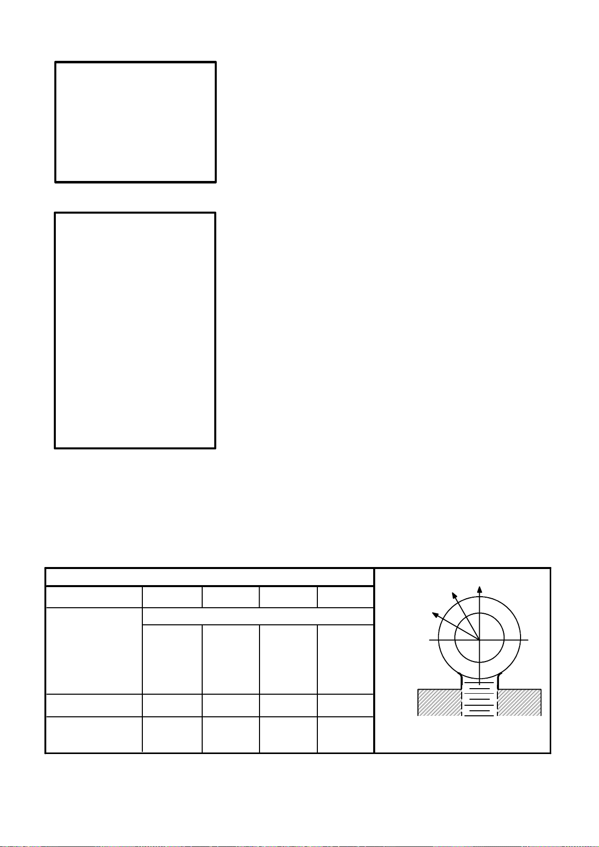
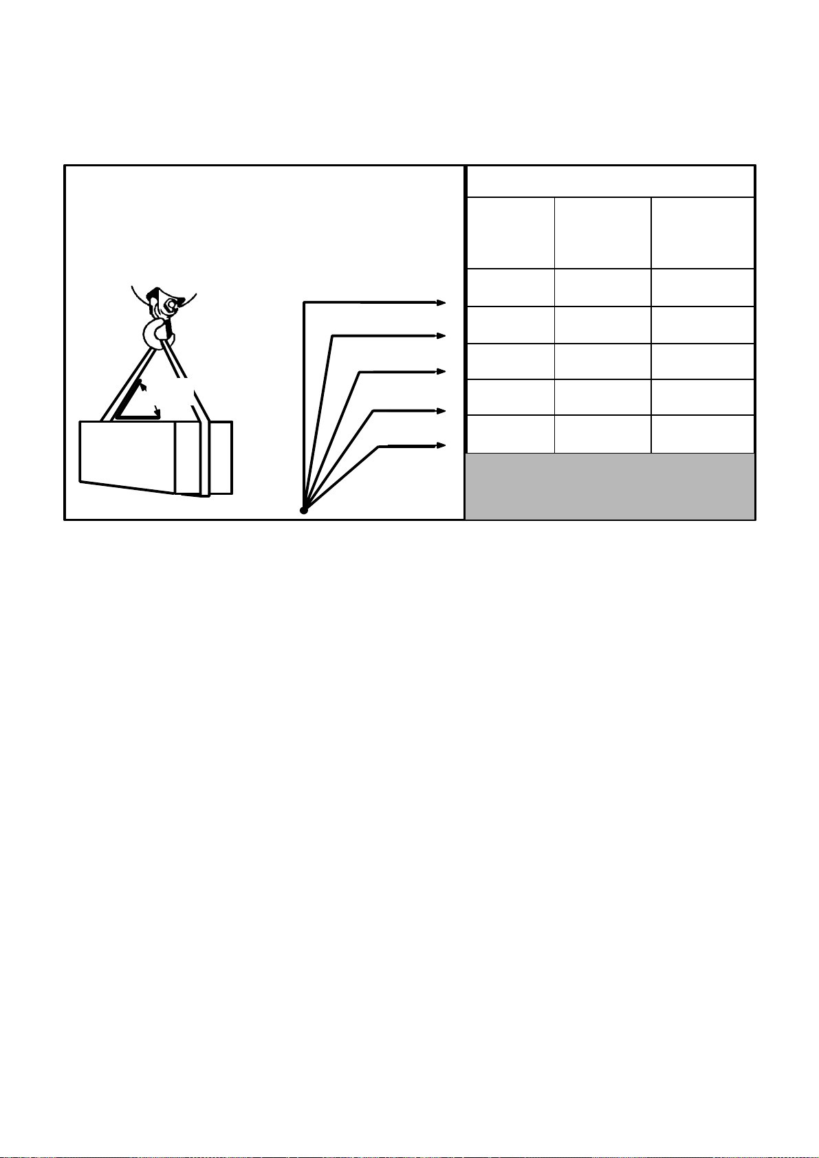
EYEBOLTS
A straight lift is preferred when using eyebolts. An angular lift places
additional stresses on an eyebolt, above that of the load to be hoisted.
Ifthesituationnecessitates an angularlift,the safe workingload for angular
lifts shown in Fig. 1 and Fig. 2 should be used.
Whenmultiple eyeboltprovisionsaredesignedintoalift, it isrecommended
(in most applications) that a spreader bar be used. (See Fig. 9 which
illustrates a typical spreader bar arrangement.)
No greater stress should be allowed than that given under Safe Working
Load in Fig. 1 and Fig. 2.
To obtain greatest strength from an eyebolt, it must fit reasonably tight in
the hole with at least 90% of the threaded length engaged.
Eyebolts should never be welded or subjected to heat in excess of 900F
[480 C].
Eyebolts should never be painted or otherwise coatedwhen used for lifting,
as such coating will very likely cover up flaws.
Eyebolts should be routinely inspected for defects and if any defects are
found,theyshouldbe destroyedbymelting,crushing,orcutting clearacross
the eye.
STRAIGHT SHANK INCH (ANSI/ASME B18.15)
THREAD .375-- 16 .500-- 13 .625--11 1.000--8
SAFE WORKING LBS. [KG]
LOAD
90 DEGREES 1000 1840 2940 7880
[453] [834] [1333] [3573]
60 DEGREES 375 805 1340 3670
[170] [365] [607] [1664]
30 DEGREES 200 470 805 2390
[90] [213] [365] [1083]
PART NUMBER 3449 870 21312 19489
IDENTIFICATION
PLATE NUMBER 3338325 3338326 3338327 3338328
60
30
STRAIGHT SHANK INCH
90
Fig. 1
Preferred Inch Lifting Eyebolts
Cincinnati Machine 91203597B001 Page 1--7
Page 21
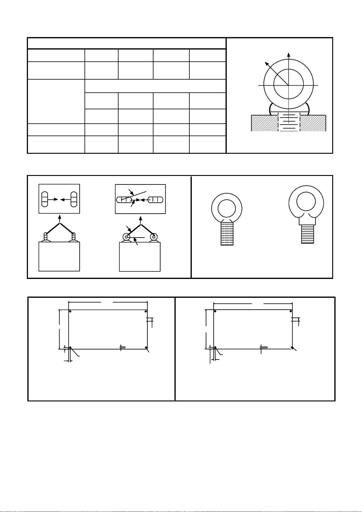
SHOULDER METRIC (ISO 3266--1984)
THREAD M12 M16 M20 M30
SPOTDIAMETER 32mm 37mm 42mm 67 mm
1.25 in. 1.50 in. 1.65 in. 2.63 in.
SAFE WORKING [KILOGRAMS] LBS.
LOAD
90 DEGREES [400] [630] [1000] [2500]
882 1389 2205 5512
45 DEGREES [100] [160] [250] [625]
220 352 551 1378
PART NUMBER 6014453--3 6014453--4 6014453--5 6014453--8
45
90
IDENTIFICATION
PLATE NUMBER 3338329 3338330 3338331 3338332
Fig. 2
Preferred Metric Lifting Eyebolts
5 MAX.
LOAD
NO
LOAD
30 MIN.
YES
YES
NO
Fig. 3
Eyebolt Loading
6.00
THIS MACHINE HAS BEEN
MANUFACTURED TO UTILIZE
”INCH” THREAD LIFTING
3.00
DEVICES. ANY EXCEPTION
TO THIS WILL BE LABELED
ADJACENT TO THE LIFT
POINT.
.12
.12
TYP.
NO 21 (.032) GAGEALUMINUM.-- NO. AL5052 ALLOY. ETCHEDAREAS TO
BEBLACK BAKEDENAMEL.ETCHEDDEPTHTO BE .003 TO .005 INCHES
------ OR ------ NO. 21 (.032) GAGE
ALUMINUM WITH METALPHOTOPROCESS.ALL LETTERING TO BEHELVETICA MEDIUM.
.109 DIA.THRU
4PLACES
3375984
.08
.25
.12 R
Fig. 4
Eyebolt I.D. Plates -- Inch and Metric
3TYP.
NO 21 (.032) GAGE ALUMINUM.-- NO. AL 5052 ALLOY. ETCHED AREAS TO BE BLACK
BAKED ENAMEL.ETCHED DEPTH TO BE .003 to .005 INCHES ------ OR ------ NO. 21 (.032)
GAGE ALUMINUM
WITH METALPHOTOPROCESS. ALLLETTERING TOBE HELVETICA MEDIUM.
SURFACE GRAIN TORUN PARALLEL TO LETTERING WITH SATINFINISH.
INCH
.375--16 UNC
THIS MACHINE HAS BEEN
MANUFACTURED TO UTILIZE
”METRIC” THREAD LIFTING
DEVICES. ANY EXCEPTION
75
TO THIS WILL BE LABELED
ADJACENT TO THE LIFT
POINT.
1.4
THRU--4
3TYP.
PLACES
3338325
SHOULDER METRIC
ISO METRIC
150
6.3
3375983
2
3R
3338329
M12
Fig. 5
Instruction Plate -- Inch (Part Number 3375984)
Page 1--8
Fig. 6
Instruction Plate -- Metric (Part Number 3375983)
Cincinnati Machine 91203597B001
Page 22
HOIST RINGS
A
PAR
T.N
O
PLATE
Hoist Rings are superior to eyebolts for angular lifting.
Be certain the thread projection is in accordance with the manufacturer’s
recommendation.
Do not recut any damaged threads on hoist rings.
To obtain the safe working load, torque to the recommended values shown
in the table below.
Fig. 7
Hoist Ring
CM HOIST
RING
PARTNO.
3346225 1 .375--16 12.0 16.3 1000 450 866 390 707 318 500 225 5013055 001
3346225 2 .500--13 28.0 38 2500 1130 2165 975 1767 795 1250 562 5013055 002
3346225 3 .625--11 60.0 81.3 4000 1810 3464 1559 2828 1273 2000 900 5013055 003
3346225 4 1.000--8 230.0 312 10000 4500 8660 3897 7071 3182 5000 2250 5013055 004
3346225 6 M12X1.75 27.0 36.6 2204 991 1908 859 1558 701 1102 496 5013055 006
3346225 7 M16X2 59.0 80 3857 1736 3340 1503 2726 1227 1928 868 5013055 007
3346225 8 M20X2.5 100.0 136 4736 2132 4103 1846 3349 1507 2369 1066 5013055 008
3346225 9 M30X3.5 229.0 310 9257 4166 8016 3607 6544 2945 4628 2083 5013055 009
CM HOIST
RING
PARTNO.
3346225 1 .375--16 12.0 16.3 1000 450 1000 450 1000 450 5013055 001
3346225 2 .500--13 28.0 38 2500 1130 2500 1130 2500 1130 5013055 002
3346225 3 .625--11 60.0 81.3 4000 1810 4000 1810 4000 1810 5013055 003
3346225 4 1.000--8 230.0 312 10000 4500 10000 4500 10000 4500 5013055 004
3346225 6 M12X1.75 27.0 36 2204 991 2204 991 2204 991 5013055 006
3346225 7 M16X2 59.0 80 3857 1736 3857 1736 3857 1736 5013055 007
3346225 8 M20X2.5 100.0 136 4736 2132 4736 2132 4736 2132 5013055 008
3346225 9 M30X3.5 229.0 310 9257 4166 9257 4166 9257 4166 5013055 009
Fig. 8
Hoist Ring Table
THREAD
SIZE
THREAD
SIZE
THREAD
TORQUE
Ft--Lb N--m Lb kg Lb kg Lb kg Lb kg
THREAD
TORQUE
Ft--Lb N--m Lb kg Lb kg Lb kg Ft--Lb N--m
Observe all other safety precautions normally practiced on eyebolts.
FF
90
_
WW
MAX. WT
EACH RING
FF
90
_
WW
MAX. WT
EACH RING
FF
60
_
WW
MAX. WT
EACH RING
FF
90
WW
MAX. WT
EACH RING
FF
45
_
WW
MAX. WT
EACH RING
FF
90
WW
MAX. WT
EACH RING
FF
30
_
WW
MAX. WT
EACH RING
NOTE F=FORCE W=WEIGHT
CM IDENT.
P
CM IDENT.
PART. NO.
.xxx--xx
PLATE
RT. NO.
.xxx--xx
.
Cincinnati Machine 91203597B001 Page 1--9
Page 23

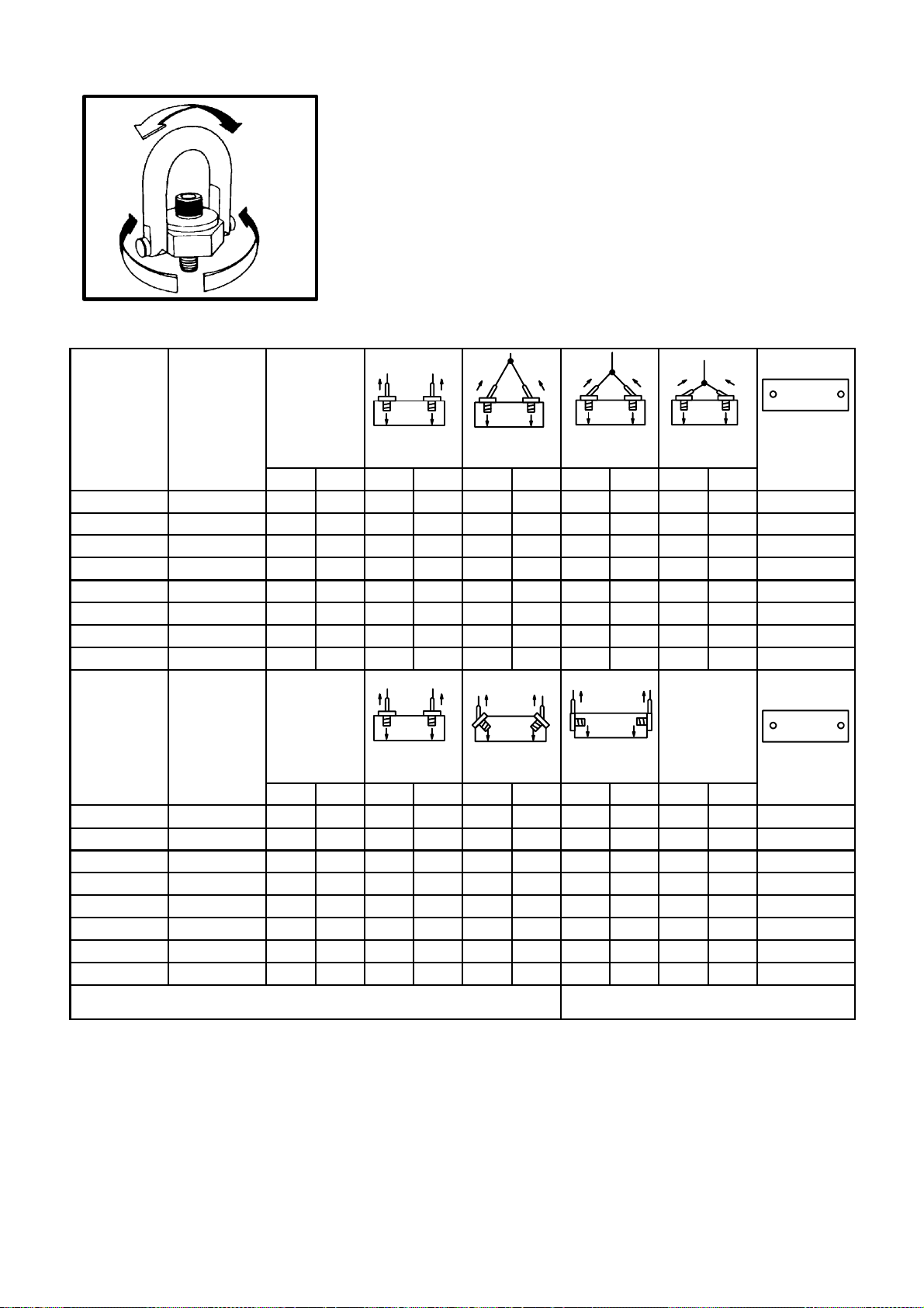
SPREADER BARS AND LIFTING BEAMS
p
y
p
SPREADER
TO LOAD TO LOAD
Fig. 9
S
reader Bar -- T
ical
Spreader bars are used when multiple eyebolts are designed into a lift.
Always observe the following safety precautions when using a spreader bar
or lifting beam
Do not exceed the safe working load.
Use the spreader or beam to handle parts or components only for which it
was designed.
Inspect it before each use.
Do not alter or weld anything to bar or beam.
Store properly to avoid damage.
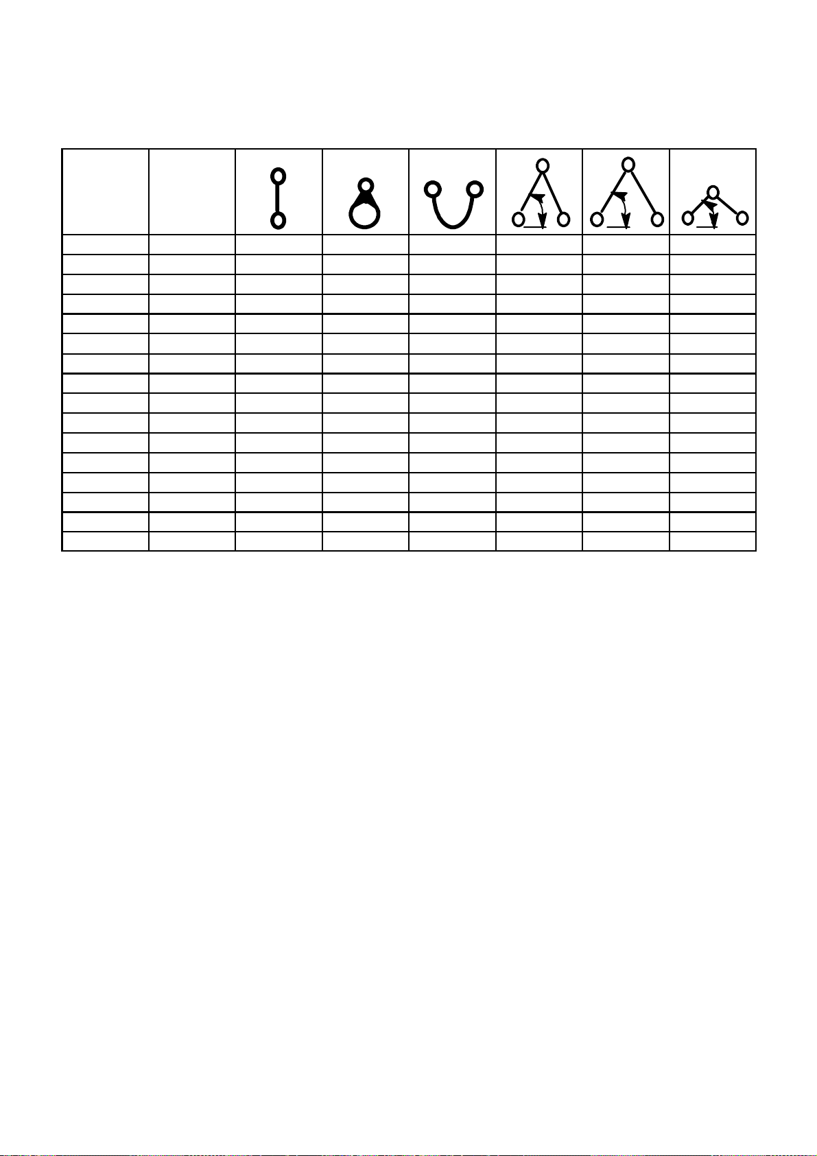
CHAIN
Selectachainwiththesuitablecharacteristics and capacityforthe load. See
above. Always observe the following safety precautions.
Do not shorten chains with knots, bolts, or any non--approved method.
Never use damaged chain.
Hitch chain securely to the load.
Pad sharp cornerswith materialof sufficientstrength to withstand load and
protect chain.
Page 1--10
Cincinnati Machine 91203597B001
Page 24

DOUBLE SLING CHAINS
SIZE OF
CHAIN
9/32 in. lbs. 3 250 5 625 4 600 3 250 8 400 6 900 4 875 8400 6900 4 875
.7.2 mm kg. 1 475 2 550 2 085 1 475 3 810 3 130 2 210 3 810 3 130 2 210
3/8 in. lbs. 6 600 11 400 9 300 6 600 17 100 13 950 9 900 17 100 13 950 9 900
9.5 mm kg. 2 995 5 170 4 220 2 995 7 750 6 330 4 490 7750 6 330 4 490
1/2 in. lbs. 11 250 19 700 15 900 11 250 29 250 23 850 16 875 29 250 23 850 16 875
712.7 mm kg. 5 100 8 845 7 210 5 100 13 270 10 820 7650 13 270 10 820 7650
5/8 in. lbs. 16 500 28 600 23 300 16 500 42 900 34 950 24 750 42 900 34 950 24 750
15.9 mm kg. 7 480 12 970 10 570 7 480 19 460 15 850 11 230 19 460 15 850 11 230
3/4 in. lbs. 23 000 39 800 32 500 23 000 59 700 48 750 34 500 59 700 48 700 34 500
19.1 mm kg. 10 430 18 050 14 740 10 430 27 080 22 110 15 650 27 080 22 110 15 650
7/8 in. lbs. 28 750 49 800 40 700 28 750 74 700 61 050 43 125 74 700 61 050 43 125
22.6 mm kg. 13 040 22 590 18 460 13 040 33 880 27 690 19 560 33 880 27 690 19 560
1in. lbs. 38 750 67 100 54 800 38 750 100 650 82 200 58 125 100 660 82 200 58 125
25.4 mm kg. 17 580 30 440 24 860 17 580 45 650 37 290 26 260 45 650 37 290 26 260
1 1/4 in. lbs. 57 500 99 600 81 300 57 500 149 400 121 950 86 250 149 400 121 950 86 250
31.8 mm kg. 26 080 45 180 36 880 26 080 67 770 55 320 39 120 67 770 55 320 39 120
1 1/2 in. lbs. 80 000 138 500 113 000 80 000
38.1 mm kg. 36 290 62 820 51 260 36 290
1 3/4 in. lbs. 100 000 73 200 41 000 100 000
44.5 mm kg. 45 360 78 560 63 960 45 360
2in. lbs. 130 000 225 000 183 000 130 000
50.8 mm kg. 26 750 102 060 83 000 26 750
SINGLE
CHAIN
90
TYPE D
60 45 30
TRIPLE SLING CHAINS
TYPE T
60 45 30
QUAD SLING CHAINS
TYPE Q
60 45 30
Fig. 10
Steel Alloy Chains
Keep hands and fingers from between the chain and load.
Avoidshockloading-- particularlywhenworkingat temperaturesbelow40
F[4 C].
Never pull chain from under load when load is resting on chain.
Correct kinks and twisting in chain before lifting.
Lift from center of hooks. Avoid lifting from the point.
Assurethatloadisfreeto move beforelifting.Keepclearof all obstructions.
When using a basket hitch, balance load and assure that chain legs contain
or support load from the sides above the center of gravity.
Storechainsin an area where they will notbe subject to mechanicaldamage
or corrosive action.
Cincinnati Machine 91203597B001 Page 1--11
Page 25
CABLE SLINGS
Select the appropriate size wire rope and hitch. See Table below.
CABLE
SIZE
1/4 in. lbs. 980 740 1400 1700 1400 980
6.4 mm kg. 445 335 635 770 635 445
1/2 in. lbs. 3600 2800 5200 6400 5200 3600
712.7 mm kg. 1630 1270 2360 2900 2360 1630
3/4 in. lbs. 7800 5800 11100 13600 11100 7800
19.1 mm kg. 3450 2630 5035 6170 5035 3450
1in. lbs. 13400 1000 18800 22000 18800 13400
25.4 mm kg. 6080 4540 8530 9980 8530 6080
1 1/4 in. lbs. 19600 14800 28000 34000 28000 19600
31.8 mm kg. 8890 6710 12700 15420 12700 6710
1 1/2 in. lbs. 28000 20000 40000 48000 40000 28000
38.1 mm kg. 12700 9070 18140 21770 18140 12700
1 3/4 in. lbs. 38000 28000 54000 66000 54000 38000
44.5 mm kg. 17240 12700 24490 29940 24490 17240
2in. lbs. 50000 36000 70000 86000 70000 50000
50.8 mm kg. 22680 16330 31750 39000 31750 22680
Fig. 11
Wire Rope Slings
ESTIMATED
RATINGCA-
PACITY
(For Exact
Rating Check
Sling Tag)
VERTICAL
CHOKER
HITCH
BASKET
HITCH
60 45
30
Guide loads with a tag line when practical.
When using multiple leg sling, select longest one possible.
Examine for damaged or worn area.
Attach securely to load.
Pad sharp corners to protect wire rope.
Center load in the base (bowl) of the hook to prevent hook point loading.
Do not kink, twist, or loop legs.
Keep hands and fingers from between wire rope and load.
Stand clear of attached load.
Start lift slowly to avoid shock injury.
Do not pull wire rope from under a load when the load is resting on it.
Do not shorten sling by knotting, by wire ropeclips, or by any other means.
Do not inspect wire rope by passing barehands over the body.Brokenwire,
if present, may puncture the hands.
Keep wire rope well--lubricated to prevent corrosion.
Page 1--12
Use gloves at all times when handling.
Cincinnati Machine 91203597B001
Page 26
SYNTHETIC MATERIAL SLINGS
Select the sling with the suitable characteristics and capability for the load
and environment. See Fig. 12.
AS THE SLING TO LOAD ANGLE
DECREASES, SO DOES THE RATED CAPACITY OF A SLING.
SLING--TO--LOAD ANGLE IS ALWAYS
THE ANGLE BETWEEN THE SLING LEG AND
THE HORIZONTALSURFACE.
SLING
TO
LOAD
ANGLE
Fig. 12
Sling Load Angle Chart
USE THIS CHART
FOR ALL TYPE
SLINGS; ROPE,
CHAIN, OR NYLON.
90
75
60
45
30
RATEDSLING CAPACITY--ONE LEG
SLING
LIFTING
EFFICIENCY
100.0 %
96.6 %
86.6 %
70.7 %
50.0 %
If Sling Ca-
pacity
at 90
is...
(LB. [KG])
1000
[454
]
1000
[454
]
1000
[454
]
1000
[454
]
1000
[454
]
Then Actual
Sling Capacity
is ...
(LB. [KG])
1000
[454
]
968
[439
]
866
[390
]
707
[320
]
500
[225
]
When using a choker hitch, the sling shall be long enough to assure that the
choking action is on the webbing.
Slings used in a basket hitch shall have the load balanced.
Do not drag slings over the floor or any abrasive surface.
Do not twist or tie knots in slings.
Never pull sling from load when the load is resting on it.
Protect sling from sharp corners and abrasive surfaces.
Do not drop slings.
Store slings in an area where they will not be subject to mechanical or
chemical damage.
Do not use where acid conditions exist.
Do not use polyester and polypropylene slings where caustic conditions
exist.
Do not use polyester and nylon slings at temperatures in excess of 180
F nor polypropylene slings at temperatures in excess of 200 F.
Do not use aluminum fittings where caustic conditions exist.
Cincinnati Machine 91203597B001 Page 1--13
Page 27
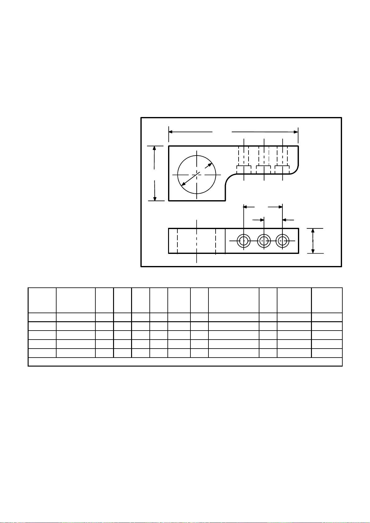
P TYPE HOOKS
N
O
P type hooks are a proprietary design and should be considered for heavy
(machine and unit) lifts.
Fig. 14 gives dimensional data, safe working loads andscrewtorquevalues
for P type hooks.
The use of these hooks must be shown on the assembly drawing, listed in
the Bill of Material and shown in the lifting section of the ServiceManual.
B
D
C
F
E
Fig. 13
“P” Type Lifting Hooks
PART
NO.
.
402517 1800 [818] 2.00 9.75 4.50 3.00 2.50 -- -- -- 2415 2 160 217
296513 2500 [1136] 1.75 10.63 4.00 2.50 4.00 -- -- -- 2415 2 160 217
296514 3500 [1590] 2.00 12.25 4.50 3.00 2.50 5.00 2415 3 160 217
402335 5000 [2273] 2.25 12.25 4.50 3.00 5.00 -- -- -- 180139 2 370 502
296515 8000 [3636] 2.25 15.75 4.50 3.00 4.00 7.88 180139 3 370 502
Fig. 14
“P” Type Lifting Hooks
LIFTING SCREW SCREW
CAPACITY
LBS. [KG]
A B C D E F SCREW NO. QTY.
INCH INCH INCH INCH INCH INCH
WHEN DESIGNING METRIC SIZES SEE THE CURRENT LIFTING MANUAL
TORQUE TORQUE
LB./FT. N--m
S HOOKS
A
The use of S hooks in conjunction with some of the other lifting devices
dictates additional safety rules which must always be practiced.
Never use more than one S hook in a single chain link or hook.
Inspect the S hook before each use and if damaged destroy by cutting into
two pieces.
Neverexceed the safe workingload which should be stamped on each hook.
Do not paint, weld, or expose an S hook to high heat.
Page 1--14
Cincinnati Machine 91203597B001
Page 28
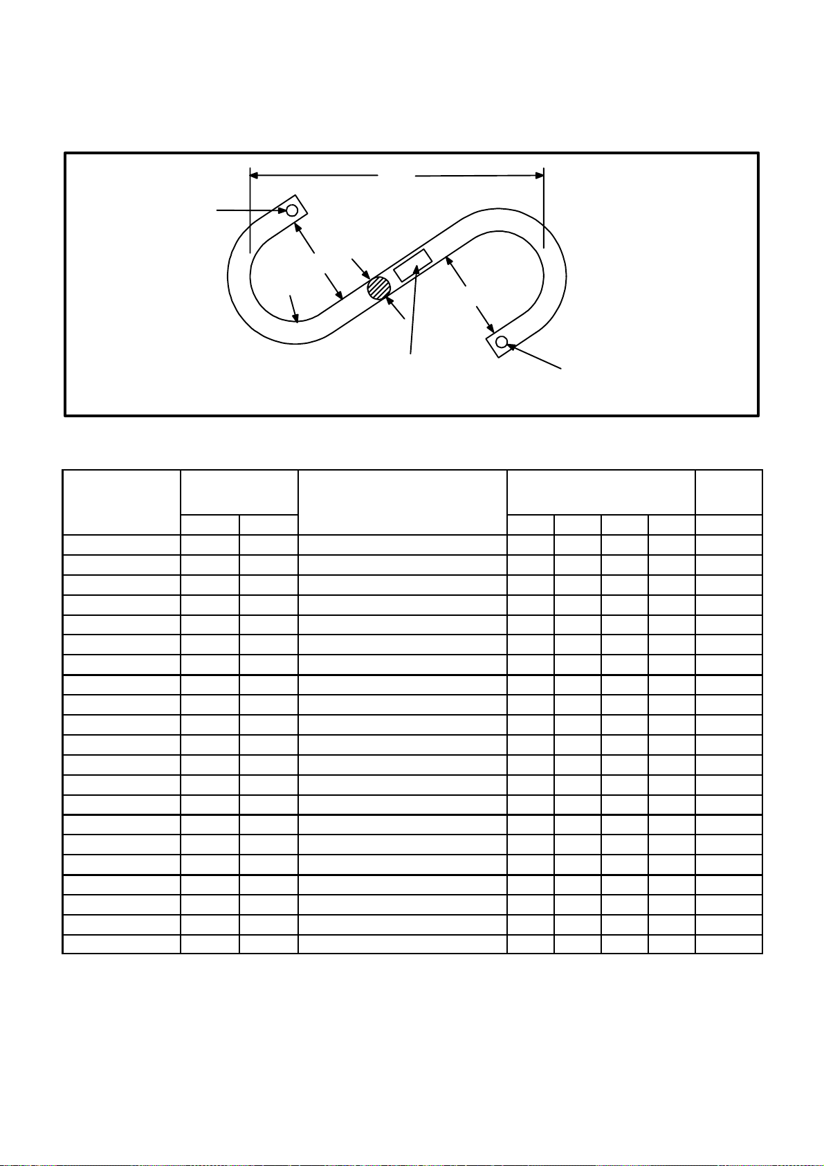
STAMPTO
INDICATE ALLOY
Do not use when either or both S hooks are opened more than 15% of the
normal throat opening or twisted more than 10 from the plane of the
unbent hook.
B
A
C
R(REF.)
STAMPWORKING LOAD LIMIT WITHLOW STRESS
CHARACTERS PER NUCLEAR AMERICAN
SOCIETY OF MECHANICAL ENGINEERS CODE
SECTION III,DIV. 1, PARAGRAPH NA--3766.6 (2)
C
STAMP MFGR. NAME OR TRADEMARK FOR
IDENTIFICATION
Fig. 15
“S” Hooks
PARTNO.
MAX. WORKING
LOAD
LBS. KG
MANUFACTURER AND
CODE NUMBER
ALL DIMENSIONS IN
INCHES
(See Fig 16.)
S--HOOK
WEIGHT
A B C R LBS.
3590535--5 650 294 CM Chain 562250 0.500 7.50 2.00 1.00 0.80
Amer. Chain & Cable 5933--00800 0.500 5.50 1.50 0.75 0.63
3590535--7 1 015 460 CM Chain 562262 0.625 9.00 2.50 1.25 1.60
Amer. Chain & Cable 5933--01000 0.625 7.00 1.88 0.94 1.30
3590535--8 1 465 664 CM Chain 562275 0.750 10.50 3.00 1.50 2.60
Amer. Chain & Cable 5933--01200 0.750 8.25 2.25 1.12 2.10
3590535--9 1 990 902 CM Chain 562287 0.875 12.00 3.50 1.75 4.20
Amer. Chain & Cable 5933--01400 0.875 9.62 2.62 1.31 3.40
3590535--10 2 600 1179 CM Chain 562300 1.000 13.00 4.00 2.00 6.00
Amer. Chain & Cable 5933--01600 1.000 11.00 3.00 1.50 5.10
3590535--12 3 290 1492 CM Chain 562310--B 1.125 15.00 4.50 2.25 8.70
Amer. Chain & Cable 5933--01800 1.125 12.12 3.38 1.69 7.00
3590535--14 4 065 1843 CM Chain 562325--B 1.250 16.00 5.00 2.50 11.70
Amer. Chain & Cable 5933--02000 1.250 13.75 3.75 1.88 10.00
3590535--15 4 915 2229 CM Chain 562337--B 1.375 17.00 5.50 2.75 15.40
Amer. Chain & Cable 5933--02200 1.375 14.88 4.12 2.06 13.00
3590535--16 5 850 2653 CM Chain 562350--B 1.500 18.00 6.00 3.00 19.50
Amer. Chain & Cable 5933--02400 1.500 16.50 4.50 2.25 17.50
3590535--18 9 500 4309 Amer. Chain & Cable 5933--02800 1.750 19.25 5.25 2.62 28.00
3590535--20 12 500 5669 Amer. Chain & Cable 5933--03200 2.000 22.00 6.00 6.00 41.00
3590535--25 19 000 8618 Amer. Chain & Cable 5933--04000 2.500 27.50 7.50 9.75 79.00
Fig. 16
“S” Hooks
Cincinnati Machine 91203597B001 Page 1--15
Page 29
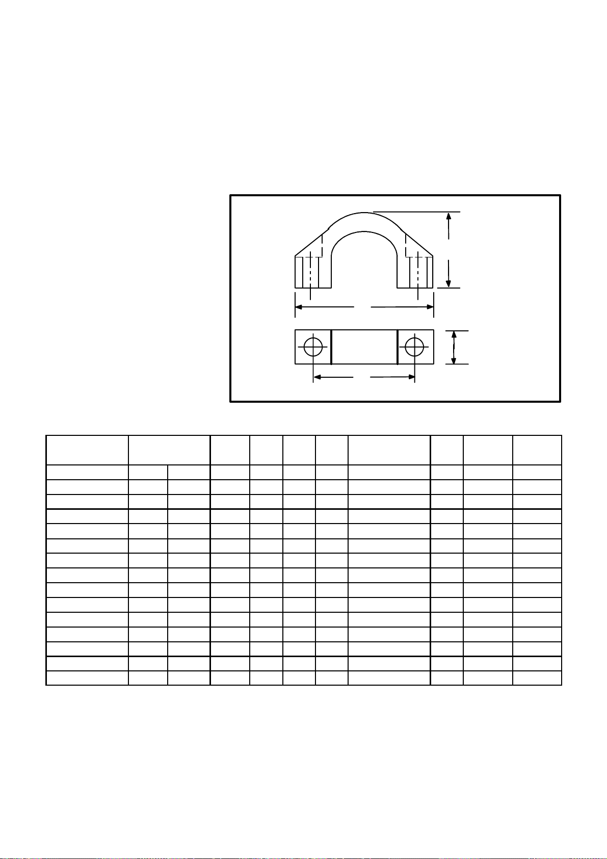
U TYPE HOOKS
U type hooks are a proprietary design and should be considered for heavy
(machine and unit) lifts.
Fig. 17 and Fig. 18 give dimensional data, safe working loads and screw
torque values for U type hooks.
The use of these hooks must be shown on the assembly drawing, listed in
the Bill of Material and shown in the lifting section of the ServiceManual.
C
B
D
A
Fig. 17
“U” Type Lifting Hooks
LIFTING SCREW SCREW
PARTNO.
303427 1 500 [680} 2.75 4.00 2.25 1.25 3248 2 45 61
303429 3 500 [1587] 3.25 4.50 2.50 1.50 2400 2 90 122
301269 6 000 [2720] 4.00 6.00 3.75 2.00 2415 2 160 217
301270 8 000 [3600} 5.00 6.50 3.88 2.25 180139 2 570 502
301271 12 000 [5442] 6.00 8.00 4.50 2.50 308196---3 2 735 997
301272 16 000 [7256] 7.00 9.50 5.30 3.00 308197---4 2 1290 1749
311105 25 000 [11 337] 7.00 14.25 6.00 3.50 308197---4 2 1290 1749
990819 1 500 [680] 75 107 60 32.0 1234074 2 41 30
3988405 3 000 [1360] 90 120 65 38.0 1234100 2 108 80
3990821 6 000 [2720] 105 155 95 50.0 1400264 2 230 170
5024235 8 000 [3600] 130 180 103 57.2 1400400 2 407 300
5025776 14 000 [6500] 170 250 133 76.2 6010088--3 2 1356 1000
5026032 22 500 [10 200] 300/180 380 159 88.9 6010088--3 4 1356 1000
CAPACITY
LB. [KG] in in in in SCREW NO. QTY. LB./FT. N--m
LB. [KG] mm mm mm mm SCREW NO. QTY. N--m LB./FT.
A B C D
TORQUE TORQUE
Fig. 18
“U” Lifting Hook Table
Page 1--16
Cincinnati Machine 91203597B001
Page 30
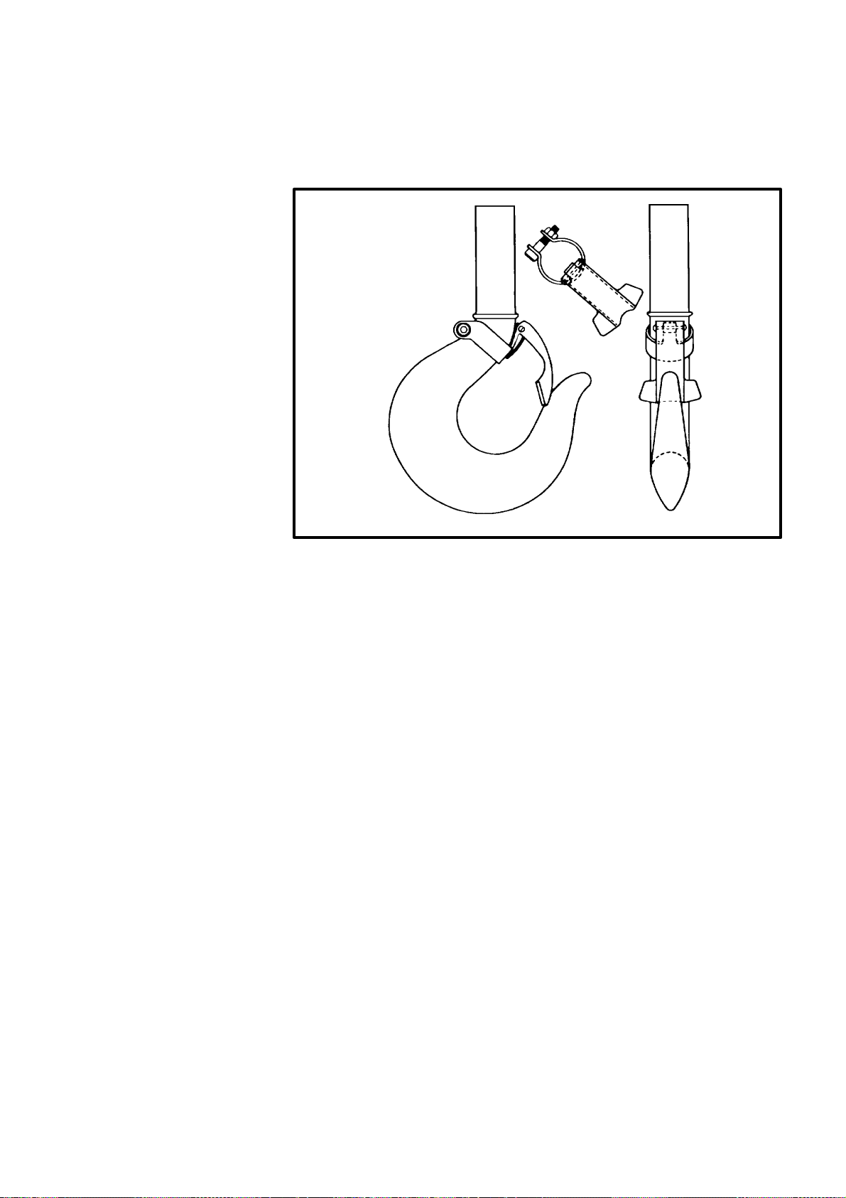
GENERAL SAFETY LIFTING INFORMATION
Allhooks or cranes or any othertype lifting device should be equippedwith
a safety latch (see Fig. 19) similar to the one manufactured by the
Harrington Co., Plymouth Meeting, Pennsylvania.
Fig. 19
Safety Latch
Illustrations or descriptions of any special lifting devices or techniques
required for servicing components of a specific machine are found in the
section dealing with the particular component.
Always contact the nearest Cincinnati Machine representative if there are
any questions regarding the lifting of any machine components.
Cincinnati Machine 91203597B001 Page 1--17
Page 31

WARNING
CUTTING FLUIDS
When soluble coolants
areused, it is important to
ensure that recommended concentration
levels are maintained.
Fluids Used With Machine Tools
General Considerations
Various fluid products, such as cutting fluids, lubricants, etc., are used with
this machine tool. The correct type and quantity is identified by instruction
platesonthemachineand/or writteninstructions inthesuppliedmanual(s).
Before using fluids or related products not specifically approved or
recommended with this machine tool, the owner/user should contact the
authorized supplier, closest Cincinnati Machine regional field office for
assistance in determining if the product is suitable for the particular
application.
Lubricants
Only those lubricants (oils and greases) tested and approved by Cincinnati
Machine, should be used in Cincinnati machine tools. For information
concerning latest lubricants manual, contact Cincinnati Machine service
department.
Cutting Fluids
Before filling the machine, ensure that the product is suitable for the
application. Frequently, check for storage, tank unit or hose leaks.
Watermixedfluids thatcontainemulsifiersmustbeprotectedfromfreezing.
Cutting fluid products should be tailored to each machine tool application
and workpiece requirement for maximum efficiency. See WARNING.
Failure to follow this Instruction can cause corrosion of safety critical
parts, resulting in machine damage and/or personal injury.
For assistance in determining the correct cutting fluid, contact nearest
Cincinnati Machine Service Department.
Sources Of Information -- USA
Beforeusinganyfluidproductwiththismachinetool,theowner/usershould
request a Technical Data Product Safety Sheet (for example: OSHA Form
20 or a similar technical data information sheet) f rom the product
manufacturer. This data should include the following:
Fire and Explosion Hazard Chemical and Trade Name
Data Acute Toxicity Properties
Spill or Leak Procedures Hazardous Ingredients
Special Protective Information Physical Data
Special Precautions Recommended Dilutions
Page 1--18
Cincinnati Machine 91203597B001
Page 32

Listed below are some other sources which can be contacted to obtain
additional up--to--date information concerning the safe use, handling,
storage and disposal of products, materials, chemicals or substances.
Occupational Safety and Health Resource Conservation and
Act (OSHA) Public Law Recovery Act (RCRA) Public Law
Department of Transportation National Institute for
(DOT) Hazard Classification— Occupational Safety and
The Transportation Safety Act Health (NIOSH)
Product Safety Data Sheet Cincinnati Machine
Toxic Substances Control Act P.O. Box 9013
(TSCA) Public Law Cincinnati, Ohio 45209
Federal Insecticide, Fungicide and American National Standards
Rodenticide Act (FIFRA) Public Institute, Inc. (ANSI)
Law
American Conference of
Environmental Protection Agency Governmental Industrial
Hygienists,
Threshold Limit
Federal Hazardous Substances Act Values
Clean Water Act
After receiving the data, analyze and perform the necessary procedures to
assure the safe handling, storage, use and disposal of the product.
Emergency/FirstAidproceduresand training should be readilyavailableto
personnelhandlingor usingproductswhichmaybehazardous(flammable),
harmful (toxic) and/or reactive (unstable)
The owner/user should become familiar with and keep informed on all
regulated materials or substances. Copies of the latest regulated material
may be obtained from agencies, such as NIOSH, Registry of Toxic Effects
for Chemical Substances, U.S. Department of Health Education and
Welfare, Public Health Service, Center for Disease Control, and the
National Institute for Occupational Safety and Health.
Usage Information
Products must not be mixed with other products unless permission and/or
instructionshavebeengrantedbythemanufacturer(s).Productconcentrates
must be mixed and diluted exactly as instructed by the manufacturer for a
particular approved application.
All product CAUTION, WARNING and DANGER labels, tags and printed
instructions accompanying the products must be read and followed This
instruction shall remain with the product at all times. Additional product
instruction labels, signs, etc., should be acquired and displayed with
concentrates that are purchased in bulk and then dispensed in small or
diluted quantities
Cincinnati Machine 91203597B001 Page 1--19
Page 33

Cutting Fluids -- Preventative Maintenance
SeeCautions1and2
CAUTION 1
COOLANTS
It is not recommended that
neat mineral oils be used as
a cutting fluid for this machine.
Failure to heed this warning
could seriously impair the efficiency of both the coolant
and swarf removal systems.
CAUTION 2
COOLANTS
It is not recommended that
coolants having a high demulsification factor, be used
with this machine.
Such coolants must be
checked for compatability
withtheoils and greasesrecommended for use with this
machine.
Failure to follow this instruction can lead to lubrication
problems, resulting in damage to the machine.
Cutting fluids are designed to cool and lubricate t he tool tip while in a cut.
There are many types of cutting fluids, some of which may cause various
problems on a machining center tool, such as corrosion, bacteria build--up,
solid formations of chips and cutting debris, etc. if incorrectly applied.
The user should be aware of these potential problems, and guard against
them.
Two types of cutting fluids can be used on this machine, semi--synthetics,
andemulsions. Eachhasitsownadvantagesand disadvantagesandtheuser
should consider all of them when making a product selection.
Water Quality
Water is the major ingredient in a water--basedcutting fluid. Its importance
in product performance cannot be ignored.
Corrosion, residue, scum, rancidity, foam, excess concentrate use, in fact
almostany cutting fluid performance problem may be causedbythequality
of the water used in making the mix.
Too Soft
Whenthemixwaterhasatotalhardnessoflessthat75ppm,thecuttingfluid
may foam -- especiallyinapplicationswherethereisagitation. Foamcauses
problems when it overflows the reservoir, the m achining center,the return
trenches,etc. Foammayalsointerferewithsettlingtypeseparators,obscure
the workpiece, and diminish t he cooling capacity of a water--based cutting
fluid. Generally, all products foam more readily in soft water.
Too Hard
Hard water, when combined with some water--based cutting fluids,
promotes the formation of insoluble soaps. The dissolved minerals in the
water combine with anionic emulsifiers in the cutting fluid concentrate to
form these insoluble compounds that appear as a scum in the mix. Such
scum coats the sides of the reservoir, clogs the pipes and f ilters, covers
machining centers with a sticky residue, and may cause sticking gauges,
pushbuttons, selector switches, and other similar devices.
Page 1--20
Hard water can promote corrosion of machine components and should
always be eliminated. De--ionized water will help deal with the problem of
hard water, provided advice has been sought.
Cleaning The Coolant Reservoir
The system requires periodic attention and servicing. The reservoir should
be drained and cleaned periodically to remove sediments and prevent
conditions that lead to deterioration of the coolant. The reservoir can be
cleaned by removing the used fluid before adding and circulating a
commercial cleaner or as required by adding a suitable cleaner to the used
coolant in the machining center during a shut--down period while the
machineis cycling. Specificcleaning procedures should be suppliedonthe
label of each cleaning product.
Cincinnati Machine 91203597B001
Page 34

Lifespan
The lifespan of cutting fluids varies widely and depends on many factors.
Thebasictypeofcoolant,thehardnessofthe water,thetypesofmetalinthe
coolant tank, the cleanliness of the system, and the amount of tramp oil in
the fluid, all are factors that affect lifespan.
Tramp Oil
Tramp oils need to be controlled. Tramp oils in the coolant mix cause a
varying degree of degradation of the coolant quality.
Minimizetheleakageofoilsintothesystem through proper maintenance of
sealsandlubricantsystems. If excess quantities of oils leak into the system,
the metalworking fluid performance can be reduced. Lubricating and
hydraulic oils contain food for bacteria. They may also blanket the fluid,
excluding air, and thereby provide ideal conditions for the growth of odor
producing bacteria. If allowed to build up, extraneous oil causes smoking
and increases residue around the machining center area.
The elimination of tramp oils is even more important if chemical cutting
fluids are used. Hydraulic oil is a contaminant that must be kept out of the
cutting fluid. Hydraulic oils, and particularly some of the additives
formulatedintothem,cancauseseriousdamagetothemachinetooland
cutting fluid when mixed with water.
Iftrampoilbuild--upshouldbecomeaproblem,variouscommercialdevices
are available to remove it.
Filtering
The cleanliness of the coolant is very important in regards to the reliability
of the various coolant valves, tubing, etc. This Machining Center is
equipped with a coolant filter system. It is good practice to ensure that any
filters are kept in good operating condition.
Rust Prevention
When a machining center tool is sitting idle for a period, the possibility of
corrosionincreases. There arecertainprecautions that the user must taketo
prevent damage to the precision ground surfaces on this machine tool.
Under certain conditions, damage can occur within as little time as a day or
two; therefore, it is important that proper precautions be carried out.
Ifthemachiningcenterisgoing to sit idle foraperiod,itisimportanttowipe
all the coolant off the slideways and then protect them with a good
rust--preventive. On the horizontal axes of the machining center, it may be
necessarytoruntheslidesbackandforthanumberoftimes,wipingtheways
each time, until no coolant is seen originating from under the slide.
After the coolant is clear from under the slide, spray the rust--preventive on
thewaysandmovetheslideagain,takingtherust--preventivebackunderthe
slide.
Cincinnati Machine 91203597B001 Page 1--21
Page 35

WARNING 1
Donotexpose PCBoardsto
electro--static discharge,
as intermittent board failures may occur and cause
erratic machine operation.
Failure to follow this
instruction may result in
personal injury.
WARNING 2
Qualified electrical personnel must disconnect all
electrical power before
printed circuit boards are
replaced. Failure to follow
this instruction may result
in personal injury.
WARNING 3
Do not set PC Boards in
styrofoam, waxed, rubber,
plastic or other high rated
non--conductive (dielectric)
materials. Failure to follow
this instruction may result
in personal injury.
Printed Circuit Board Handling Instructions
General
All integrated circuits are susceptible to electro--static discharge damage.
Because of this condition, special procedures must be used when handling
circuit boards containing integrated circuits, even though there is no
completelyfoolproof system of protecting integrated circuits. Metal oxide
semi--conductor (MOS) assemblies manufactured byVickers Electronic
Systems Division Incorporatedaresupplied with acautionsticker. Referto
the sticker and the information concerning cautions and warnings in the
supplied literature.
NOTE: It is important to emphasize that electro--static discharge to a PC
Board may not completely destroy an assembly component, but
severely de--grade this component to a point where intermittent
failures may occur .
If static discharge occurs at sufficient magnitude (2kV or greater) damage
or degradation will usually occur i f recommended handling procedures are
notused. Personnelhandling equipment in a lowhumidity environmentcan
generate static potentials in excess of 10kV. Do not touch any integrated
circuit assemblies at the pins, leads or edge connectors, since most damage
is done at these points. See WARNING 1.
Recommended Handling Procedure
Before removing or replacing any PC Board, a qualified technician must
disconnect all electrical power, including battery back--up devices. Refer
to the machine dedicated electrical diagrams. See WARNING 2.
A recommended procedure before handling printed circuit boards is as
follows:
1. Attach a grounded ”wrist strap” in contact with the skin. This strap
should have a resistor value of 1 megohm (1/2 watt) in series with
the person and grounded to leak off electro--static discharge.
2. When working with static control devices (for example: a bag or
pad), touch the device with your grounded hand. This action will
place you and the static control device assembly at the same
electro--static potential.
Store and transport the printed circuit boards in static control bags. Use
”shortingbars”or conductive foam materials. Donot use a suspected static
damaged printed circuit board. See WARNING 3.
Below are examples of electro--static caution symbols which may appear in
areas of concern (for example: packing, shipping or receiving). These
symbols signify that the ”Recommended Handling Procedures” must be
used and/or follow any special supplied instruction.
Page 1--22
Cincinnati Machine 91203597B001
Page 36

Safety Features
WARNING 1
PERIMETER GUARDING
It is imperative that this
guarding is kept intact
and in place at all times
during normal operation
of the machine.
In such cases where the
part of the guarding has
tobe removed formaintenance purposes, the
guardingMUSTbereplaced before the machine is allowed to go
back into normal operation.
Failure to follow this
instruction may result in
serious personal injury.
WARNING 2
Perimeter Guarding
A complete set of perimeter guards is supplied and fitted to this machine.
See WARNING 1.
OPERATOR ACCESS TO THE MACHINE is gained at the following
point(s):--
1. Operator Door -- for loading and unloading components and for
setting up purposes.
Operator Sliding Door(s)
See WARNING 2.
With the door(s) closed and machine power on, a safety switch is actuated
that allows automatic machine movements to be executed.
OPERATOR DOOR
POWER LOSS
If machine power is lost
while the door is in its
closed position, it will re main latched in that position until power is re--applied.
The door can be opened
from the inside using the
special key attached to the
underside of the SHOT
BOLTbody. Do not attempt
tooperate the machine with
this door open.
Failure to follow this
instruction may result in
serious personal injury.
It is not possible to open the operator door/s while the machine is in
automatic cycle, due to the latching mechanism of t he switch.
With the door(s) open and machine power on, the following conditions
apply:
With the door(s) open and machine power on, the following functions are
available under HOLD TO RUN control.
S Spindle rotation is inhibited.
S Power feed of the X and Z axes are limited to 2m/min maximum.
The following functions are also available for selection.
1. Coolant Start.
2. Tailstock quill movement.
3. Spindle chuck open/close.
Cincinnati Machine 91203597B001 Page 1--23
Page 37

CAUTION
Emergency Stop
Actuatingthisbuttonwiththe
machine in a cutting cycle
may damage cutting tools
and work pieces.
Failure to follow this instruction may resultin damageto
equipment.
DANGER
The ELECTRICAL ISOLATION switch does NOT isolate the incoming supply to
the electrical cabinet or the
supply to the transformer
unit. Use extremecare when
working near the power inputleads.Severeshockinjury can result if the leads are
touched.
Feed Hold Push Button
Provides logical and safe interruption of the active machine cycle when
actuated.
Emergency Stop Push Button
See CAUTION.
Providesfastestpractical elimination of machinemovements(spindle,axes
and mechanisms, etc.).
Electrical Isolation Device (Main Disconnect Switch)
A lockable isolation switch is provided on the main electrical cabinet.
See DANGER.
It should also be noted that it may take up to 20 minutes to discharge
completely the capacitors mounted in the servo drives.
Air Supply Isolation Valve
A pneumatic isolation valve is required to be provided by the customer to
allow for the removal of air power from the machine.
Metric Lifting Points
This machine has been manufactured to utilise “METRIC” thread lifting
devices. Any exception to this will be labelled adjacent to the lift point.
Failure to follow this instruction may result in death or
serious personal injury.
Page 1--24
Cincinnati Machine 91203597B001
Page 38

WARNING 1
Failure to follow instructions on this page may result in serious personal injury.
Machine Related Safety And Usage Notes
Axis Overtravel Condition
Care should be taken when power feeding an axis out of axis overtravel
condition,to ensurethatthedirectionselectedbrings the axisawayfromthe
overtravelcondition. Ifthewrongdirectionisselecteditispossible to drive
theaxisfurtherintoovertravelwhich could result in damageto themachine.
Safe Operation Of Lathe Chucks
Ensure the chuck is of good condition as damage may impede its safe
function especialy at high speeds.
Maximum operating speeds for chucks are for guidance only and attention
should be made to the size and shape of the workpiece and t ooling.
The influence of centrifugal force may result in the work piece becoming
insucurelygrippedundercertainconditions. Asthefactorsvarywidelywith
each particular application we are unable to provide specific figures for
general use, but the following should be observed;
1. Speed for an application
2. Weight and type of jaws if non--standard
WARNING 2
Inadequately supported
bar--stock protruding
from the headstock may
cause whipping. Ensure
the material is correctly
supported at all times.
3. Radius at which jaws are operating
4. Condition of chuck
5. State of balance
6. Magnitude of the cutting forces
7. Clamping force applied to the work--piece
When a manual chuck or fixture is used, remove the clamping handle from
the chuck or fixture after tightening and before operating/rotating the
spindle or moving the axes.
Work Holding Devices
Always support the work--piece using the correct work holding device, eg.
chucks, steadrests and centres.
Care should be taken to support work--piece when clamping/unclamping.
Safe maximum speedof rotation should be observed, as determined by the
work holding device manufacturer.
Bar stock protruding from the end of the headstock should be adequately
supported at all times. See Warning 2.
Failure to follow this
instruction may result in
serious personal injury.
Cincinnati Machine 91203597B001 Page 1--25
Page 39

WARNING
Failure to follow instructions on this page may result in serious personal injury.
General Operation
Loosentool holder/cutting tool bolts gradually. Keep stablefooting and do
not overtighten these bolts. Check with the manufacture for proper
re--torquing values.
Securelytightenalltoolholders,toolschuckjaws. Balancingof theseitems
may be necessary. Check with the manufacture for proper re--torquing
values.
Always use two spanners to lock cutting tools into a ’Driven Head’ tool
holder. One spanner is located on the rotating spindle unit within the head
whilst the other locates on the spindle locknut, see Fig. 20.
Fig. 20
Driven Head Tool Holder
CAUTION
Attemptingto lock orunlock a
tool in a Driven Head tool
holder whilst it is mounted in
a turret stationmay causeexcessive torsional strain in the
spindle drive mechanism.
Failure to follow this instruction could result in serious
damage to the drive tang on
the Driven Head tool holder
and drive mechanism.
Never attempt to lock or unlock a tool in a Driven Head when the head is
mounted in a tool station on the turret. See CAUTION.
Always use a bench m ounted propriety Tightening Fixture to lock and
unlockatool from a Driven Headtoolholder. Fordetails,seemanufacturers
catalogue.
Atoolholderoraplasticblankingplugshouldbepresentineachoftheturret
tool stations. Blanking plugs (shown in Figure 32) are recommended to
occupyturretstationsnotinusetopreventtheingressswarfand coolant, etc.
See manufacturers catalogue.
Lower the spindle s peed when changing the speed range while the spindle
is rotating.
Do not insert bar stock into a rotating spindle. The bar stock length should
be shorter than the spindle‘s length.
Bar stock must be straight in order to prevent vibration.
Do not attempt to remove chips if t he spindle, turret or any machine
component is in motion.
Page 1--26
Cincinnati Machine 91203597B001
Page 40

WARNING
Improper handling of lith ium batteries may cause
the batteries to explode,
spraying caustic metal,
and causing severe
chemical burns.
Failure to follow this
instruction may result in
serious personal injury.
Check that the cycle is complete (Cycle Start indicator is not illuminated)
andthemachineis inaFeedholdconditionbeforeattemptingtounload/load
a workpiece.
Before starting the machine operation (machining), check hydraulic
pressures,lubricatingoil pressures, compressedairpressure--if present,and
chuck pressure to make sure all gauges indicate proper values.
Battery Replacement
The battery installed in the control unit willprovide backupfor the memory
content for approximately 12 months. If an alarm message is displayed on
the screen replace the battery as soon as possible. For the correct battery
replacement procedure refer to thecontrol manufacturers operating manual.
FANUC alarm message “BAT”.
Lithium Batteries
Lithium batteries contain the hazardous chemical lithium --an extremely
active chemical requiring special handling and disposal. The following
guidelines should be observed when handling lithium batteries:
Lithium batteries are not rechargeable.
Do not allow lithium batteries to be heated above 212 degrees F (100
degrees C).
Do not incinerate lithium batteries.
Do not expose lithium batteries to water. Water may cause a violent
reaction.
Do not try to disassemble lithium batteries. Direct contact with the
metal causes severe chemical burns.
Because of the hazardous nature of lithium, disposal must be made
according to applicable federal, state, and local regulations.
Cincinnati Machine 91203597B001 Page 1--27
Page 41

Chapter 2 System Information
Fig. 21
Hawk Turning Center
WARNING
MISUSE OF THE MACHINE
The machine must not be
adapted to carry out any
form of MILLING or GRINDING operations, as its design and construction does
not allow for these to be
performed safely.
Failureto heed this warning
could result in serious personal injury if not death.
Introduction
The CINCINNATI HAWK range of Turning Centers is a general purpose
cold metal turning machine, which use non--rotating tools with an indexing
turret.
The machine has two sliding axes and tool turret indexing capability all
under numerical control.
The turning center has been designed to automatically index tools in order
to carry out turning, drilling, threading, boring and reaming operations.
Allfunctionsofthemachinemaybecontrolledbythe NC program, with the
minimum of operator attention being required.
The perimeter guarding provided, ensures the safety of personnel against
movingparts,coolant,swarfand broken tooling, when the aboveoperations
are being undertaken. See WARNING. See also GUARD STRENGTH.
Cincinnati Machine 91203597B001 Page 2--1
Page 42

WARNING 1
GUARD STRENGTH
For safe use of this
machine the guards must
be in place and properly
maintained. Care must be
taken to ensure that cutters are applied within
their designed safe speed
and that any separate
component parts of cutters are securely clamped
prior to application.
Failure to follow this instruction may result in serious personal injury.
Guard Strength
The guards of this machine are designed to prevent access to hazardous
movingpartsandtocontaintheejectionoftool or work--piece fragments up
to a calculated maximum energy level.
For Hawk 150 machines the maximum energy level is 2480 Joules.
Thisisequivalent toamassof1.25 kgejectedfromthework areaandhaving
an impact speed of 63 m/s.
For Hawk 200/250 machines the maximum energy level is 8000 Joules.
This is equivalent to a mass of 2.5 kg ejected from the work area and
having an impact speed of 80 m/s.
See WARNING 1.
Page 2--2
Cincinnati Machine 91203597B001
Page 43

Noise
Noise level for this machine is within a maximum of 80 dB(A).
The operating conditions used to determine this figure were as follows:
1. Machine correctlyinstalled,clearofallnearbyreflectingsurfaces with
all guards fitted and closed.
2. Noise Measurement positions 1.6m high at operator’s work--station
and at six equi--spaced positions along a peripheral path 1.0 from the
outer surface of the machine.
3. Noise levels measured using an integrating sound level meter.
4. Machine warmed prior to testing by running for at least 30 minutes at
a spindle speed of 66% of max RPM.
5. A--weighted time--averaged emission sound pressure levels measured
at each position under the following conditions:
5.1 Machine stopped (hydraulics off) to get background pressure
level. Levels recorded in dB(A) using ’slow’ setting.
5.2 Spindle running at maximum speed with chuck jaws gripping a
dummy workpiece. Emission pressure levels, L
peq
θ
recorded in
dB(A) using ’slow’ setting.
5.3 Machine performing turning operation as detailed in clause 6.2
below, with time--averaged emission pressure levels being
recorded, L
peq
.
θ
6. Operating conditions:
6.1 Mode 1: Running Light Test
Spindle Speed: 5500rpm (Hawk 150)
Workpiece: 34mm diameter (dummy)
Workpiece holding: 3 j aw chuck
6.2 Mode 2: Prescribed Turning Test
Workpiece: EN 302
Workpiece dimensions: 155mm long, 70mm diameter
Workpiece holding: 3 j aw chuck
Tooling type: Indexable insert, sintered carbide,
rhomboidal
Tooling geometry: Nose radius: 0.8 mm; Back rake: +9
Cutting edge angle: 95
Spindle speed: 1000 rpm
Feedrate: 250 mm/min
Depth of cut: 2.0 mm
3
Metal removal rate: 110 cm
/min
Length of cut: 113 mm
Duration: 27s
Cincinnati Machine 91203597B001 Page 2--3
Page 44

WARNING
NOISE LEVEL
Running the machine at
high speeds with chuck
jaws wide open, could generate noise of a level
deemed to be injurious to
the hearing of operators or
bystanders. Under such
circumstances the use of
hearing protection is required.
7. All noise emission values corrected for background level.
8. Noise declaration
DECLARED SINGLE--NUMBER NOISE EMISSION VALUES in
accordance with ISO 4871, L
Maximum A--weighted emission sousnd pressure level L
pAd
pAd
, (ref.
20←Pa)attheoperator’spositionoranyperipheralposition,indecibels:
Mode 1: Running light at max. spindle speed: 80
Mode 2: Under prescribed operating conditions: 77
9. The operating conditions described herein are considered to be
adequately representative of the product, and reflect prevailing usage.
Noise levels, under different operating conditions, may, however,
exceed the limits quoted, and could under extreme conditions
necessitate the use of ear protection equipment. See WARNING.
Failureto heed this warning
could result in serious personal injury.
CAUTION
Avoid locating the machine
near welding , electrical, or
magnetic generating equipment. Possible generating
electrical noise may result in
machine control interference.
Failure to follow this instruction may result in damage to
equipment.
Fumes And Coolant Misting
Extraction equipment can be fitted to the machine. When machining
materials which might produce fumes or result in coolant misting, note
should be taken of local health and safety regulations.
Fire Hazard
The machine has not been designed to cater for materials which, as a result
of the machining application, could combust. It is the owner’s/user’s
responsibility in these circumstances to conform with local safety regulations for handling and machining such materials.
Should further advice be required on any of the above items the request
shouldbeforwardedtoone of the offices detailed atthe frontof thismanual.
Machine Location -- See Caution
EMC Directive Requirements
This machine satisfies the EMC Directive by conforming to generic
emissions and immunity standards for the INDUSTRIAL ENVIRONMENT ONLY.
Install the machine in a clean, well lighted area. Ambient temperatures
should remain relatively constant to maintain accurate alignment between
components, and there should be enough air s pace around the machine to
dissipate heat built up during operation. Avoid particularly a location near
shipping doors, etc. where air temperatures in winter can fluctuate widely.
Page 2--4
Ensure there will be enough room around the machine to access its
componentsformaintenanceandoperation. Suitable lifting devices willbe
required for assembly, servicing , and loading/unloading of workpieces.
Cincinnati Machine 91203597B001
Page 45

WARNING
In order to clearly show
details of this machine,
some covers, shields,
doors or guards have either been removed or
shown in an ’open’ position. All such protective
devices shall be installed
in position before operating this machine.
Failure to follow this instruction may result in
damage to machine components and/or personal
injury
NC Control
The machine operating station is mounted and positioned at the front of the
machine guarding, Protect the control from dust and extremes of
temperature and humidity.
Machine Information
Themachineand controlareintegratedto compriseanefficientmanufacturingsystem.Thus,m achining cycles can be completely automatic,including
toolselection,toolpositioning,selectionofspindlespeedsandcuttingfeeds,
coolant control with other related auxiliary functions and/or combinations
of control. The machine and controls are completely compatible, each
taking advantage of the capabilities of the other.
The basic machine consists of the following units:
Fixed base
Fixed headstock/spindle
Sliding saddle (Z axis)
Sliding turret (X axis)
Multi--station indexing turret
Hydraulic chuck and cylinder
Hydraulic tailstock
Computer Numerical Control Station
Electrical Cabinet
Chip/Coolant Tray
Perimeter Guards
Bed/Base Unit Thebed/base unit is the main structure of the TurningCenter.In addition to...................
Headstock Spindle Unit The headstock spindle unit contains the necessary components t o drive the............
Saddle The sliding saddle provides the Z axis travel...........................
Turret Theturretis located on the saddle. The turret providesthe X axis travel and..........................
Chip / coolant tray The chip tray is positioned under the base at the front of the machine.................
Coolant tank Lshaped,lyingacrossthefrontandRighthandendofthemachine.Theunit.....................
providing rigidity and support for the sliding members, machine alignment
is maintained through the strength of this structure.
The unit houses the following;
Spindle drive motor
Hydraulic tank and pump unit -- bolted to the Left Hand end
of the Bed/Base unit.
Electrical Cabinet
spindle through range of speeds in one (1) RPM increments. The spindle is
powered by a motor whose speed selection is accomplished via CNC.
also carries the multi--station indexing turret.
houses the coolant pump.
Cincinnati Machine 91203597B001 Page 2--5
Page 46

Axis Orientation
+X
Fig. 22
Axis Orientation -- Hawk Turning Centre
+C
-Z
+Z
-X
Theaxisorientationphotographenablestheoperatortoaffixinhismindthe
conventional slide directions of movement for the turning center. The
photograph is for axis orientation only and does not represent the
mechanical zero reference points for these axes.
Page 2--6
Cincinnati Machine 91203597B001
Page 47

Hawk Specification
Chuck
Turn length max mm 440 540 690......................................
Jaw chuck diameter max mm 210 254 304...............................
max swing over bed mm 400 530 530...................................
max turn diameter (STD tooling) mm 240 300 350.........................
Bar chuck capacity mm 51 65 77....................................
Axis Travel Ranges
Turret slide (X axis) mm 215 245 270...................................
Saddle (Z axis) mm 440 540 690.......................................
Spindle
AC Drive Motor continuous rated kW 5.5 11 15........................
duty rated kW 7.5 15 18.5............................................
Spindle speed max rpm. 5500 4500 3300....................................
Nose . A2--5 A2--6 A2--8...............................................
Bearing type . A/C A/C A/C.........................................
Bearing size -- Bore mm. 90 110 130...................................
Units 150 200 250
Linear Axis Feedrates and Thrust
Feedrate Z m/min 24..........................................
Rapid rate Z m/min 24.........................................
Axis thrust Z kN 5.6........................................
Accuracies -- Uni--directional
Positioning Z mm 0.004........................................
Axis repeatability Z mm 0.001..................................
Tooling
Turret positions 12 12 12......................................
Index time per station s 0.2 0.3 0.3.................................
Tooling type (Standard) V.D.I.30 V.D.I.40 V.D.I.40................................
Tailstock
Quill diameter mm 65 95 95.......................................
Quill stoke mm 101 127 127..........................................
Quill thrust kN 4.5 7.8 7.8..........................................
Quill taper 4 M.T 5M.T 5M.T..........................................
X m/min 16..................................................
X m/min 16..................................................
XkN4.0..................................................
Xmm0.002..................................................
Xmm0.0005..................................................
Cincinnati Machine 91203597B001 Page 2--7
Page 48

Hawk Specification Units 150 200 250
CNC System
Model and type FANUC 21i......................................
Manufacturer G.E. FANUC........................................
Number of contouring axes ONE (X Axis).............................
Lubrication System
Axes ballscrew nuts grease P64..............................
X,Y,Z axis way bearings grease P64..........................
Spindle bearing lubrication pre--greased sealed.............................
Coolant System
Coolant delivery system -- Low Pressure at 0.9 Bar l/min 20..........
Coolant delivery system -- High Pressure at 5.2 Bar l/min 20..........
Head m 5...............................................
Tank capacity without conveyor l 135 177 190.........................
with conveyor l 155 205 218........................................
Hydraulic System
Oil specification P38......................................
Tank capacity l 45.......................................
Air Requirement
Air supply pressure bar 61...................................
Continuous volume ANR dm3/s 5..............................
Electrical Power Requirement
Spindle drive motor kVA 9 25 37...................................
Axis motors X, Z kVA 3 3 3.....................................
Turret Indexing motor kVA 1.5 1.5 1.5.................................
Hydraulic pump motor kVA 3 3 3.................................
Coolant pump motor -- Low Pressure VA 650 650 650.....................
Coolant pump motor -- Low Pressure kVA 3.5 3.5 3.5.....................
Control gear VA 750 750 750.........................................
Machine Weight/Floor Space
Machine net weight approx. kg 4000 4500 5000.............................
Overall machine height (max) m 1.62 1.8 1.8...........................
Machine width m 1.5 1.9 1.9.......................................
Machine length without swarf conveyor m 2.4 3.0 3.46
Machine length with swarf conveyor m 3.2 3.9 4.3
Allillustrationsand specificationscontainedinthis literatureare basedonthe latestproductinformation availableatthe timeof publication.
The right is reserved to make changesatanytime without notice in prices, materials, equipment, specifications,andmodelsand to discontinue models. In addition, all dimensions are nominal and can vary with machine model change.
Page 2--8
Cincinnati Machine 91203597B001
Page 49

Machine And Range Drawings
This section provides machine and range drawings for the Hawk range of
turning centers.
Z AXIS TRAVEL
E
125
125
100
B
3.45
3.0
2.4
C
4.3
3.9
3.2
D
1075
1075
804
E
250
690
DISCHARGE
HEIGHT
SWARF
CONVEYOR
FLOOR LEVEL
200
540
D
A
B
QUILL TRAVEL
C
150
HAWK
440
A
A
A
25
CNC
CONTROL
STATION
25
Fig. 23
Front View
Cincinnati Machine 91203597B001 Page 2--9
O/L LENGTH WITHOUT CONVEYOR
O/L LENGTH WITH CONVEYOR
The Information shown is general in nature. For
absolute working dimensions refer to Dedicated
Engineering Drawings supplied with the machine
Page 50

B
HEIGHT OF
MACHINE
A
’X’ AXIS
TRAVEL
The Information shown is general in nature. For
absolute working dimensions refer to Dedicated
Engineering Drawings supplied with the machine
Fig. 24
Left Side View
Page 2--10
MACHINE WIDTH
HAWK
A
B
C
C
150
215
1.6
1.5
200
245
1.8
1.9
FLOOR
250
270
1.8
1.9
Cincinnati Machine 91203597B001
Page 51

A PART OFF TOLHOLDER ADJACENT TO A SHORT
TOOLHOLDER (ON EITHER SIDE) PRESENTS VIRTUAL-
The Information shown is general in nature. For
absolute working dimensions refer to Dedicated
Engineering Drawings supplied with the machine
203 MAX.TURNING TO SPEC.
LYNO INTERFERENCE EVEN WHEN FACING DOWN TO
CENTRE. PARTING TOOL IS CLOSER TO DISC THAN
THE TURNING TOOL..
MAX BORING BAR - Ø32
TURNING TOOL- 20 X 20
DISC VDI.30.
DISC P.C.D. - 270
DISC O/DIA -340
CHUCK STD- Ø170
CHUCK SPC’L - Ø210
A LONG TOOLHOLDER ADJACENT TO A SHORT TOOLHOLDER
(ON EITHER SIDE) PRESENTS VIRTUALL YNO INTERFERENCE
187 R.TOOLING ENVELOPE.
MAX.TURNED FACE
(OUTSIDE SPEC.)
MAX.TURNING
BY SPEC
203
EVEN WHEN FACING DOWN TO THE CENTRE- LINE.
203
270
126. LARGEST DIA. BLANK IN CHUCK WHICH CAN BE
PARTED;
WITH A TURNING TOOLHOLDER IN THE NEXT AD-
JACENT POSITION
210 CHUCK
50.8 (2”) MAX. BAR. DRAW TUBE BORE 52MM
203 THEORETICAL MAX TO SPEC’N
202 R.PARTING- TOOL ENVELOPEAPPROX.
215 ’X’AXIS TOTAL WORKING STROKE
170 CHUCK
ING BY SPEC.
27.4
.
270 VDI.30,PCD
323 DISTANCE TO SPINDLE
30 VDI
340 DISC.
109.5,LARGEST COMPONENT SWING BETWEEN BORING- BARS ON AD-
JACENT TURRET POS’NS.
BORING BARS OF SIMILAR LENGTH ARE NOT RECOMMENDED TO BE PUT
INTO ADJACENT DISC POSITIONS; BUT SHOULD FOLLOW THE GENERAL
RULE OF BEING LOADED INTO THE DIAGONALLYOPPOSED STATIONS.
218 R.TOOLING ENVELOPE.
210 MAX TURNING.
LONG TOOLHOLDER.
(OUTSIDE SPEC.)
203 MAX TURN-
Fig. 25
Turning Capacity Chart -- Hawk 150 (VDI Tooling)
Cincinnati Machine 91203597B001 Page 2--11
Page 52

The Information shown is general in nature. For
absolute working dimensions refer to Dedicated
Engineering Drawings supplied with the machine
Ø254 MAX. TURNING
BY SPEC.
A PART OFF TOOLHOLDER ADJACENT
TOA SHORTTOOLHOLDER (ONEITHER
SIDE)PRESENTSVIRTUALLYNOINTER-
FERENCE EVEN WHEN FACING DOWN
TOCENTRE. PARTING TOOL ISCLOSER
TO DISK THAN THE TURNING TOOL
Ø306.5MAX. TURNED FACE
(OUTSIDE SPEC)
Ø254 THEORETICAL MAX.
TO SPECIFICATION
Ø66 DRAWTUBE
BORE
Ø254 MAX. TURNING
BY SPEC.
Ø166.5 LARGEST DIA BLANK IN CHUCK
WHICH CAN BE PARTED, WITH A TURNING
TOOL HOLDERIN THE NEXT ADJACENT POCKET
TURNING CAPACITY CHART
R262.5 PARTINGTOOL
ENVELOPE APPROX.
245 ’X’ AXIS TOTAL WORKINGSTROKE
R234.5 TOOLING
R267.7 TOOLING ENVELOPE
254 MAXTURNING BY SPEC
ENVELOPE
Ø40 VDI
Ø410DISK
Ø340 P .C.D.
R388 DISTANCE TO
SPINDLE CENTRE LINE
Ø130.5 LARGEST COMPONENT
Ø254 CHUCK
Ø200 CHUCK
SWING BETWEEN BORING BARS
ON ADJACENT TURRET POSITIONS
BORING BARS OF SIMILAR LENGTH
ARE NOT RECOMMENDED TO BE PUT
INTO ADJACENT DISK POSITIONS,
BUT SHOULD FOLLOW THE GENERAL
RULE OF BEING LOADED INTO THE
DIAGONALLYOPPOSED STATIONS.
A LONG TOOLHOLDER ADJACENT TO
A SHORT TOOLHOLDER (ON EITHER
SIDE) PRESENTS VIRTUALLY NO IN-
TERFERENCE EVEN WHEN FACING
DOWN TO THE CENTRE LINE
240 MAX TURNING (LONG TOOLHOLDER)
OUTSIDE SPEC
Fig. 26
Turning Capacity Chart -- Hawk 200 Machines (VDI Tooling)
Page 2--12
Cincinnati Machine 91203597B001
Page 53

Ø305 MAX. TURNIING
BY SPEC.
Ø356.61 MAX TURNED FACE
(OUTSIDE SPEC)
Ø196.5 LARGEST DIA BLANK IN CHUCK
WHICH CAN BE PARTEDWITH A TURNING
TOOLHOLDER IN THE NEXT ADJACENT
POCKET.
R264.7 TOOLING
ENVELOPE
A LONG TOOLHOLDER ADJACENT TO A
SHORT TOOLHOLDER (ON EITHER SIDE)
PRESENTS VITUALLY NO INTERFERENCE
EVEN WHEN PARTING DOWN TO THE
CENTRE LINE.
Ø78 DRAWTUBE BORE
R292.5 PART TOOL ENVELOPE
270 ’X’ AXIS TOTAL WORKING
STROKE.
Ø250 CHUCK.
Ø315 CHUCK.
TURNING CAPACITY CHART
R297.7 TOOLING ENVELOPE
Ø305 MAX. TURNIING BY SPEC.
290.6 MAX TURNING (LONG
Ø
TOOLHLDER) OUTSIDESPEC
The Information shown is general in nature. For
absolute working dimensions refer to Dedicated
Engineering Drawings supplied with the machine
40 V.D.I
Fig. 27
Turning Capacity Chart -- Hawk 250 Machines (VDI Tooling)
Ø162.3 LARGEST COMPONENT SWIN
G BETWEEN BORING BARS ON AD-
JACENT TURRET POSITIONS
BORING BARS OF SIMILAR LENGTH
ARE NOT RECOMMENDED TO BE PUT
INTO ADJACENT DISK POSITIONS
BUT SHOULDFOLLOW THEGENERAL
RULEOF BEING LOADED INTO THEDI-
AGONALLYOPPOSED STATIONS.
Ø305 MAX.TURNIING BY
SPEC.
Ø400 P.C.D
Ø470 DISK
A PART OFF TOOLHOLDER ADJACENT
TOA SHORTTOOLHOLDER(ONEITHER
SIDE) PREENTS VIRTUALLY NO INTER-
FERENCE EVEN WHEN FACING DOWN
TOCENTRE. PARTINGTOOL ISCLOSER
TO DISK THAN THE TURNINGTOOL.
Cincinnati Machine 91203597B001 Page 2--13
Page 54

(
V
g
)
320 SLIDE WIDTH
4356438
DUPLOMATIC INDEXER
BSA 150
The Information shown is general in nature. For
absolute working dimensions refer to Dedicated
EngineeringDrawingssupplied with themachine.
TAILSTOCK
FULLY BACK
173.7
105
101.6 QUILL
STROKE
475.8 TAILSTOCK
ADJUSTMENT
30
215 MAX STROKE
189
8
190
22
22
75
63
52 68
22
47
25
25 25
TYP’
PCLNL
2020K12.
,RAD.135
32
22
27.410
8 O/TRAVEL
27.4
8
10
35
35
173.7 O/HANG
101.6 QUILL
438MAX WORKING STROKE
8
402 STROKE TO HARD JAWS ONS.M.W. 170 CHUCK
418STROKE TOHARDJAWS ONKITAGAW A170CHUCK
123
454 ABSOLUTE STROKE
16
91
KITAGAWA170--52
STROKE
223
139
99
99
SMW--169.
OVERTRAVEL
50
3
FRONT FACE
BULKHEAD
FRONT FACE
HEADSTOCK
19
Fig. 28
Data Sheets -- Hawk 150
Page 2--14
DI Toolin
Cincinnati Machine 91203597B001
Page 55

The Information shown is general in nature. For
absolute working dimensions refer to Dedicated
EngineeringDrawingssupplied with themachine.
65.1
190
90
100
177.91
127.00
QUILL STROKE
245 MAXSTROKE
10 O/TRAVEL
TAILSTOCK
FULLY
BACK
665.50 TAILSTOCKTRAVEL
1250 TOCLEAR ’X’ TRAVEL
267.7 LONG
TOOLHOLDER
40
83
190
24
Fig. 29
Stroke -- Hawk 200 Machines (VDI Tooling)
560 ABSOLUTE STROKE
540 MAX. WORKINGSTROKE
540 TO KITAGAWA BB08--66 CHUCK FACE
539 TO SMW BHM210--A6 CHUCK FACE
255.6
SMW HARD JAWS
12082121
358.6
104
SMALL SMW
10 O/TRAVEL
388 FROM OF DISK TO OF
SPINDLE
BULKHEAD FRONT FACE
HEADSTOCK FRONT FACE
103
SMALL KITAGAWA
4 SERRATIONS
57
3
Cincinnati Machine 91203597B001 Page 2--15
Page 56

The Information shown is general in nature. For
absolute working dimensions refer to Dedicated
EngineeringDrawingssupplied with themachine.
177.91
127.00
QUILL STROKE
TAILSTOCK
FULLY
BACK
190
190
54
64.6
90
100
97.7
32
Ø40
Ø83
297.7 LONG
TOOLHOLDER
L
C
L
C
443 FROM OF DISK TO
OF SPINDLE
70 ABSOLUTE STROKE
690 MAX. WORKING STROKE
119
10
O/TRAVEL
BULKHEAD FRONT FACE
HEADSTOCK FRONT FACE
270 MAX. STROKE
10O/TRAVEL
27
690 TO SMW BBM250--A8 CHUCK FACE
56
690 TOKATAGAWA B210--A8 CHUCK FACE
179
SMALL
SMW
234.09
SMW HARD
JAWS
12082621
4 SERRATIONS
897 TAILSTOCKTRAVEL
1530.62
56
(347.09)
173
113 SMALL
KITAGAWA
Fig. 30
Stroke -- Hawk 250 Machines (VDI Tooling)
Page 2--16
Cincinnati Machine 91203597B001
Page 57

The Information shown is general in nature. For
absolute working dimensions refer to Dedicated
EngineeringDrawingssupplied with themachine.
B1;30/20:212--100--150.
RECTANGULAR TRANSVERSE
TOOLHOLDER,R.H.SHORT.
B3;30/20:212--105--150.
RECTANGULAR TRANSVERSE
INVERTEDTOOLHOLDER,
RIGHT--HAND;SHORT.
B7;30/20:222--105--150.
RECTANGULAR TRANSVERSE
INVERSE TOOLHOLDER,
RIGHT--HAND:LONG.
TYP’.35
25
35
27.4,TYP’.
20
SQ.
40
22
47
61
30.
10H6. 12H6.
OPTIONAL STANDARD
TOOLING PACKAGE.
001270504000001.
E1;30/25:222--052--150
TOOLHOLDER WITH:-INTERNALCOOLANTSUPPLY.
E1;30/32:222--055--150
TOOLHOLDER WITH:-INTERNALCOOLANTSUPPLY.
E2;30/30:212--015--156
BORINGBAR HOLDER.
16H6.
ONE SET OF FIVE LINERBUSHES.
20H6.
55
65
82.4
MAX.-- IF USINGFULL STROKE.190
17
.45
.68
68
52.
H6.32
25H6.
30H6.
71
59
25
22
H6
63
75
61
68.
75
Fig. 31
Optional Standard Tooling Package -- Hawk 150 (VDI Tooling)
Cincinnati Machine 91203597B001 Page 2--17
Page 58

The Information shown is general in nature. For
absolute working dimensions refer to Dedicated
EngineeringDrawingssupplied with themachine.
DRILL HOLDER -- VDI 40 Dia 32
(WITHINTERNAL COOLAND SUPPLY)
FORM E1
27.4032
DIN 69880
PARTING O FF BLADE HOLDER -- VSI 40 --
RIGHT HAND
32.SH32
32.4032
TURNING TOOL -- VDI 40 -- RIGHT HAND LONG
FORM B5
11.4025/20
OPTIONAL STANDARD TOOLING
DIN 69880 PART 3
PACKAGE 1946177
TURNING TOOL -- VDI 40 -- RIGHT HAND SHORT OVERHEAD
FORM B3
6.4025/20
DIN 69880 PART 3
TURNING TOOL -- VDI 40 -- RIGHT HAND SHORT
FORM B1
5.4025/20
DIN 69880
BORINGBAR HOLDER -- VDI 40 Dia 40
FORM E1
27.4032
Ø32
Ø74 Ø52
DIN 69880
75
22
BORINGBAR SLEEVE
Ø25
28.4025
PLASTIC PLUG -- VDI 40
FORM Z2
29.40K
DIN 69880
BORINGBAR SLEEVE
Ø20
28.4020
ONE SET OF FOURLINER BUSHES
COLLET CHUCK -- VDI 40 ER32 TYPE
FORM E4
30.4032
DIN 69880
90
76
BORINGBAR SLEEVE
Ø16
28.4016
Ø20 H6 Ø25 H6
Ø16 H6
Ø40
78
BORINGBAR SLEEVE
Ø12
Ø83 Ø40
Fig. 32
Optional Standard Tooling Package -- Hawk 200/250 Machines (VDI Tooling)
Page 2--18
28.4012
Ø12 H6
Cincinnati Machine 91203597B001
Page 59

gOp
190.
130. 185.
Ø130 Ø185
60.
Ø60
138.9
138.9
108.9
108.9
156.9
156.9
SMW.KSZ,MB60.
COLLET CHUCK.
24
24
49 MIN
SMW.HARD JAW
1282030.CM#:--
1270486000001
82
22
10.5
10.5
21
21
SERRATIONS.
OFJAW
4
4
160
150
24
24
23
SMW.210,BH D.
72 MAX
72,MAX.
49,MIN.
19
37
45
45
C’BORE
FORM12.
52.
23
Ø52
210
Ø210
M12
92
98
165
165
COLLET CHUCK.
KITAGAWACRL60.
22
22
HARD JAWS
HB,08A1.CM#:- -
1270575000001
M10
12
12
24
24
25
156
156
111
111
KITAGAWAB208,A5.
22
22
25
138.
Ø138 Ø150
60.
Ø60
148
148
M10
210
Ø20
,MIN.45.5
68.7,MAX.
STROKE3.7
18
PERJ AW.
45.5 MIN
68.7 MAX
C’BORE
FORM10.
52.
Ø52
91
91
108
108
63.5,MAX.
46.5,MIN.
46.5 MIN
SMW.HARD JAW
12081621.CM#:--
1270485000001
67
67
45
45
10
21
20
20
139
139
99
99
24
24
21
10
20
SMW--170--52
63.5 MAX
C’BORE
FORM10.
14
20
52
52.
170.
Ø170
M10
The Information shown is general in nature. For absolute
working dimensions refer to Dedicated Engineering Drawings supplied with the machine.
Fig. 33
Work Holdin
tions -- Hawk 150
HARD JAWS
HB,06B1.CM#:- -
1270572000001
12
12
123
M12
123
91
91
15
15
67.5
67.5
13
KITAGAWA170--52
8.5
13.75
48,MIN.
60,MAX.
C’BORE
FORM10.
M10
20
20
M10
52.
Ø52
170.
Ø170
50
50
BULKHEAD FRONT FACE
HEADSTOCK FRONT FACE.
3
Cincinnati Machine 91203597B001 Page 2--19
Page 60

The Information shown is general in nature. For
absolute working dimensions refer to Dedicated
EngineeringDrawingssupplied with themachine.
KITAGAWA CHUCKING SYSTEM
Ø165
Ø150
Ø65
140
17
100
21
3
120
21
3
57
Ø75 254
B210--A6 CRS66--A6
25
57
BULKHEAD FRONT FACE
HEADSTOCK FRONT FACE
BULKHEAD FRONT FACE
HEADSTOCK FRONT FACE
BB08--66
Fig. 34
Work Holding Options -- Hawk 200
Page 2--20
Ø200Ø66
86
17
57
BULKHEAD FRONT FACE
HEADSTOCK FRONT FACE
103
21
3
Cincinnati Machine 91203597B001
Page 61

The Information shown is general in nature. For
absolute working dimensions refer to Dedicated
EngineeringDrawingssupplied with themachine.
BHM--250--A6
SMW CHUCKING SYSTEM
Ø250
Ø75
105
124
24
57
Ø210
BULKHEAD FRONT FACE
HEADSTOCK FRONT FACE
321
Ø66
92
BBM--210--A6
17
57
BULKHEAD FRONT FACE
HEADSTOCK FRONT FACE
104
21
3
Fig. 35
Work Holding Options -- Hawk 200
Cincinnati Machine 91203597B001 Page 2--21
Page 62

The Information shown is general in nature. For
absolute working dimensions refer to Dedicated
EngineeringDrawingssupplied with themachine.
❤
❤
❤
❤
❤
❤
❤
220
200
❤
KITAGAWA CHUCKING SYSTEM
B212--A8
CDC80A2 (1273393)
11mm
STROKE
159
20
77
18
30
304
91
170
❤❤❤❤
71
BULKHEAD FRONT FACE
HEADSTOCK FRONT FACE
❤❤❤❤
3
110
122
B210--A8
Fig. 36
Work Holding Options -- Hawk 250
100
71
33
113
71
77
BULKHEAD FRONT FACE
HEADSTOCK FRONT FACE
254
75
18
77
BULKHEAD FRONT FACE
HEADSTOCK FRONT FACE
Page 2--22
Cincinnati Machine 91203597B001
Page 63

gOp
|
The Information shown is general in nature. For
absolute working dimensions refer to Dedicated
EngineeringDrawingssupplied with themachine.
SMW CHUCKING SYSTEM
315
95
BHM 315-- AB
30
77
BULKHEAD -- FRONT FACE
HEADSTOCK -- FRONT FACE
111
136
71
3
250
77
BBM 250--A8
19
77
BULKHEAD -- FRONT FACE
HEADSTOCK -- FRONT FACE
105
119
71
3
Fig. 37
Work Holdin
Cincinnati Machine 91203597B001 Page 2--23
tions -- Hawk 250(Continued
Page 64

p
350
APPROX
CLEARANCE REQUIRED
5500 MIN
BEHIND MACHINE
3000 BAR CAPACITY
4900 MIN
3210 APPROX1520 APPROX
5180
CLEARANCE REQUIRED
BEHIND MACHINE
2700
450
APPROX
720
1770
1670
BAR FEEDSHOWN
ROTATED THROUGH
90° AND 135°
4800 OVERALL LENGTH
3000 BAR CAPACITY
1064
BASE
1150
PLAN VIEW OF BASE
1975
BASE
1150REF
MULTIFEED3 -- 76
SHORT MAGAZINE BAR
FEED OPTION
The Information shown is general in nature. For
absolute working dimensions refer to Dedicated
Engineering Drawings supplied with the machine
91203090A
Fig. 38
Bar Feed O
Page 2--24
tions -- Hawk 150 machines
Cincinnati Machine 91203597B001
Page 65

Motor Rating
The MTD (Machine Tool Duty) rating of the motor is based upon the
amount of power delivered in a given amount of time. The following chart
shows spindle motor MTD ratings.
7.5 kW
5.5 kW
POWER
Machine
Hawk Model 150 7.5 5.5
Hawk Model 200 15 11
Hawk Model 250 18.5 15
MTDR
Continuous
30 750 3,500
MTD Rating Continuous Use
5.0 kW
4.5 kW
5,500
Fig. 39
Hawk 150 -- Spindle Power Characteristics
15 kW
11 kW
POWER
30 750 4,500
SPEED RPM
MTDR
Continuous
SPEED RPM
Fig. 40
Hawk 200 -- Spindle Power Characteristics
Cincinnati Machine 91203597B001 Page 2--25
Page 66

15 kW
11 kW
POWER
MTDR
Continuous
30 575 3,300
Fig. 41
Hawk 250 -- Spindle Power Characteristics
SPEED RPM
Page 2--26
Cincinnati Machine 91203597B001
Page 67

X+
SPINDLE
FACE
MACHINE ALIGNMENT AND PROGRAM POINTS
On Turning Centers, the Z axis travels parallel to the spindle centerlineand
the X axis travels perpendicular to the spindle centerline.
Several real and imaginary points are used to describe the relationship
between the machine elements, the tool point, and the workpiece. There are
manyreferences to these points throughout themanual.Thissectiondefines
themachinesetupandalignmentpoints. RefertoMachineRangedrawings.
Z+
Z*
CHUCK
SPINDLE
CENTERLINE
Fig. 42
Machine Alignment And Program Points
X*
MACHINE ZERO
OD COMMON
TOOLPOINT
ATGRIDALIGN
POSITION
Machine Zero
Machine zero in the X axis is located on the spindle centerline.
Machine zero is established only once each time the machine is startedand
aligned. The control calculates all automatic range checking and interference parameters from machine zero.
NOTE: When coordinate reset is active and the machine is aligned, pro-
gram zero is also located at this point.
Cincinnati Machine 91203597B001 Page 2--27
Page 68

Chapter 3 Functional Description of Controls
Introduction -- GE FANUC 21i--TA CNC System
The GE Fanuc 21i--TA CNC system control consist of a Control mounted
behindflatscreenwithsoftkeys,MDIkeypad,OperatorsControlPanel,and
an MTB panel (Machine Tool Builders panel).
ForfulldescriptiononusingthePCMIAslot and softkeysonthecontrol/flat
screen unit and also the MDI keypad unit reference should be made to GE
FanucOperatorsmanual (21i--TAB--63084EN)suppliedwiththismachine.
The Hawk Turning centre is arranged with GE Fanuc 21i--TA Computer
Numerical Control System comprising an operator control station with a
9.5” high resolution monochrome flatscreen display. See Fig. 43.
Control/Flat Screen/Softkeys MDI Keypad
PC MIA
Slot
(SRAM)
Card
-- +
RS 232 Serial Data Port
Fig. 43
Control Station Layout for:
-- Hawk Turning centres with fanuc 21i TA
F
3
x
--
1
0
X
+X
-- Z + Z
-- X
+--
Operators
Control
MTB Panel
0
Cincinnati Machine 91203597B001 Page 3--1
Page 69

123 45678910
A
B
C
D
RS 232
E
F
Fig. 44
Operators Control Panel
X
Z
x
A
1
100%
+-U
AUX
X
1
X1 X10 X100
1
-- +
+
X
--
+X
X
-- Z
-- X
OPERATOR PANEL -- PUSHBUTTON DESCRIPTIONS
REF DESCRIPTION REF DESCRIPTION
A1
A2
A3
A4
A5
A6
A7
A8
A9
A10
B1
B2
B3
B4
B5
B6
B8
B9
B10
C1
C2
C3
C4
Memory Operation C5 Turret Jog -- (decrement)
EDIT mode C6 AUX 1 -- spare membrane key
MDI Operation C8 -- Z axis JOG/MPG axis selection
Align Machine C9 Rapid traverse
Jog mode C10 +Z axis JOG/MPG axis selection
Parts catcher down D1 Program restart
Parts catcher up D2 Tool Setting Arm Down (active)
Chuck -- ID Grip D3 Tool Setting Arm Up (stowed)
Chuck -- OD Grip D4 Spindle speed decrement
Offset measure D5 Spindle 100%
Single block D6 Spindle speed increment
Block delete D8
Optional stop D9 --X axis JOG/MPG axis selection
MPG mode x 1 D10
MPG mode x 10 F1 Cycle start
MPG mode x 100 F2 Cycle stop
F3 Program stop
+X axis JOG/MPG axis selection F4 Spindle clockwise (CW)
F5 Spindle stop
Dry run F6 Spindle counterclockwise (CCW)
Program test F8 Coolant On
Axes inhibit F9 Coolant Off
Turret Jog + (increment) F10 Coolant Auto
+Z
Page 3--2
Cincinnati Machine 91203597B001
Page 70

AUTOMATIC OPERATION -- PROGRAMME SOURCE
MEMORY OPERATION -- (Push button with LED) (A1)
This mode is selected to run a part programme registered in the active
programme memory. (See GE Fanuc Operators Manual -- III Operation
chapters 1.2 and 4.1).
EDIT MODE -- (Push button with LED) (A2)
This mode is selected to edit part programmes registered in the active
programme memory. (See GE Fanuc Operators Manual -- III Operation
chapters 9).
MDI OPERATION -- (Push button with LED) (A3)
This mode selection enables a programme of up to 10 blocks to be created
and processed from the MDI buffer memory. (See GE Fanuc Operators
Manual -- III Operation chapters 1.2 and 4.2).
EXECUTION PUSHBUTTONS
CYCLE START (Push button with LED) (F1)
This push button causes the active NC programme to start, providing that
the following conditions are met:--
1) All axes have been aligned.
2) The turret is aligned, i.e. ALIGN MACHINE key is
illuminated
3) No NC or Machine faults are active
4) AUTO or MDI mode has been selected
5) Operator door/s is/are closed
CYCLE STOP (Push button with LED) (F2)
Cycle stop is used to stop all feed motors and to suspend the NC cycle.
TheLEDin thisbutton isilluminatedwhenevertheCYCLESTOPisactive.
It is cancelled whenrestartingthe NC cycleusing the CYCLE STARTpush
button.
NOTE: Any active programme dwell will also be stopped by using this
push button. If CYCLE STOP is depressed during a Tapping
Cycle the NC cycle will continue until the spindle has reversed
and the axis retracted.
Cincinnati Machine 91203597B001 Page 3--3
Page 71

PROGRAMME STOP (Push button with LED) (F3)
Pressingthis push button during NC part programmedexecutioncausesthe
activecycleto be held at the end of the current programmeblock. Torestart
the active part programme, the CYCLE START push button must be
depressed.
Itispermittedtostop the spindle whilst ina programmestop condition. The
NC cycle however cannot be resumed until the spindle has been restarted.
PROGRAMME STOP push button is active in both AUTO & MDI modes
but only whilst the machine is in cycle.
The LED in this push button is illuminated when programme stop is active
and remains illuminated until the cycle is restarted or the control system is
reset.
SPINDLE CONTROL BUTTONS
SPINDLE STOP (Push button with LED) (F5)
Thispushbutton causesanimmediatespindlestop and is activeatalltimes.
If the machine is in cycle, a cycle stop is also generated.
The LED in this button is illuminated if the spindle is stopped during an
Auto Cycle interrupt condition and acts as a reminder that the spindle must
be restarted before the cycle can be resumed.
SPINDLE CLOCKWISE (CW) (Push Button with LED) (F4)
This push button can be used to restartthe spindle, once it has beenstopped
during an Auto Cycle Interrupt.
In C--Axis Mode OFF (M50 active), this button can also be used to jog the
spindle in the clockwise direction providing the control is not in cycle or in
a cycle interrupt condition, and only when the operator door is closed. See
CAUTION.
In C--Axis Mode ON (M51 active), this button, in conjunction with the
control set in JOG mode, can be used to jog the spindle in the clockwise
direction. The operator door is latched shut at all times when M51 is the
active M--code. See CAUTION. Also, see HANDWHEEL (MPG) for
alternative spindle jog facility.
SPINDLE COUNTER CLOCKWISE (CCW) (Push button with LED) (F6)
This push button can be used to restartthe spindle, once it has beenstopped
during an Auto Cycle interrupt.
Page 3--4
In C--Axis Mode OFF (M50 active), this button can also be used to jog the
spindle in the CCW direction providing the control is not in cycle or in a
cycle interrupt condition, and only when the operator door is closed. See
CAUTION.
In C--Axis Mode ON (M51 active), this button, in conjunction with the
control set in JOG mode, can be used to jog the spindle in the CCW
direction. The operator door is latched shut at all times when M51 is the
Cincinnati Machine 91203597B001
Page 72

active M--code. See CAUTION. Also, see HANDWHEEL (MPG) for
alternative spindle jog facility.
CAUTION
Spindle Jog
TheSpindle/Chuckmust be in an interference free position
before pressing the SPINDLE CW/CCW pushbutton.
Failure to follow this instruction may result in damage to
the machine, workpiece and tooling.
SPINDLE 100% (Push button with LED) (D5)
100%
+
--
This push button is used to return the actual spindle speed to 100% of the
last programmed value and to remove any active spindle speed override
imposed by means of the spindle speed increment and decrement buttons.
TheLEDin this push buttonisilluminatedallthetime that the 100%spindle
speed override is active
SPINDLE SPEED INCREMENT (Push button with LED) (D6)
This push button is used to override the programmed spindle speed. The
actual spindle speed is increase by 10% each time this button is depressed,
up to a maximum of 120% of the programmed value or the the maximum
spindle speed if this occurs sooner.
TheLEDin this pushbuttonisilluminatedoncethe 120%overrideis active.
NOTE: Spindle override is ignored whilst M48 is active
SPINDLE SPEED DECREMENT (Push button with LED) (D4)
This push button is used to override the programmed spindle speed. The
actual spindle speed is decreased by 10% each time thisbutton is depressed,
down to a minimum of 50% of the programmedvalue or the the minimum
spindle speed if this occurs sooner.
TheLED in this push button is illuminated once the 50% overrideis active.
NOTE: Spindle override is ignored whilst M48 is active
OPERATION BUTTONS
ALIGN MACHINE -- (Push Button with LED) (A4)
This pushbutton is used for referencing the machine axes and turret to the
control system. (See chapter 4 of this manual for machine and mechanism
alignment procedure).
MPG MODE (HANDWHEEL) & INCREMENT SELECTION PUSHBUTTONS
MPG MODE -- 0.001mm (Push Button with LED) (B4)
This pushbutton selects MPG Mode with 0.001mm distance move per
X1
Cincinnati Machine 91203597B001 Page 3--5
increment of the handwheel.
Page 73

X10
X100
MPG MODE -- 0.010mm (Push Button with LED) (B5)
This pushbutton selects MPG Mode with 0.010mm distance move per
increment of the handwheel.
MPG MODE -- 0.100mm (Push Button with LED) (B6)
This pushbutton selects MPG Mode with 0.100mm distance move per
increment of the handwheel.
JOG MODE -- (Push Button with LED) (A5)
This button accesses the ’axis and direction’ push button selections to
provide ’continuous move’ axis jogs. (See push button references B9, D9,
C8andC10 in this manual,andGEFanucOperatorsManual -- IIIOperation
chapter 3.2).
In C--Axis Mode ON (M51 active), manual rotation of the spindle/chuck
using the Handwheel (MPG) control is possible proivided JOG mode is
selected ON.
OPERATION SELECT -- PUSHBUTTONS
SINGLE BLOCK -- (Push Button with LED) (B1)
Thispushbuttonallowsanactivepart programmetobeprocessedone block
at a time. When this feature is active each block must be started using the
CYCLE START push button. The single block push button is enabled in
AUTO & MDI mode. The LED is illuminated when SINGLE BLOCK is
active.
NOTE: It is permitted to use this push button to interrupt an active cycle.
Foraffectofsingleblockon cannedcyclesrefer toGEFanucoperators manual.
BLOCK DELETE -- (Push Button with LED) (B2)
When BLOCK DELETE is active all programme blocks preceded by the
BLOCK DELETE character (/) are skipped during an NC cycle This push
button is enabled only in AUTO & MDI mode.
The LED is illuminated when BLOCK DELETE is active.
OPTIONAL STOP -- (Push Button with LED) (B3)
This push button enables the OPTIONAL PROGRAMME STOP feature.
Whenoptionalstopis active the NC cyclewill stop on readingan M01 code
and can only be restarted by pressing the CYCLE START push button, all
existing modal programme information is unaffectedby this function. This
push button is enabled in AUTO & MDI mode only.
Page 3--6
The LED is illuminated when OPTIONAL STOP is activate.
DRY RUN -- (Push Button with LED) (C1)
When the DRY RUN feature is active, coolant flow is inhibited and the
feedrate specified by the NC programme is ignored.
The OVERRIDE SELECTOR switch is used to modify the DRY RUN
feedrate from 0. 1M/min. to 10 M/min.
Cincinnati Machine 91203597B001
Page 74

Rapid motions are conducted as normal and can also be overridden by the
OVERRIDE SELECTOR.
This push button is enabled in AUTO & MDI mode.
The LED is illuminated when DRY RUN is active.
Dry run can only be selected when the machine is not in cycle.
To start the cycle in dry run requires a double press of the CYCLE START
push button. On the first press an operator prompt message DRY RUN
ACTIVE REPRESS CYCLE START appears on the CRTas a warning that
DRY R UN is active.
PROGRAMME TEST -- (Push Button with LED) (C2)
When the programme test feature is active, all T and S codes and all of the
M codes with the exception of:M00, M01, M02, M30, M98 and M99 are
not processed.
Thispushbutton is enabledinAUTO& MDImode.TheLEDisilluminated
when programme test is active.
PROGRAM TEST is used during programme checking and may also be
used in conjunction with AXES INHIBIT.
AXES INHIBIT -- (Push Button with LED) (C3)
XZ
Axes inhibit suppresses all axis moves. The CRT display however is
updated as if the axis were not inhibited.
Thispush button is only enabledinAUTO&MDImodewhilst not in cycle.
The LED is illuminated when AXIS INHIBIT is active.
Axes inhibit is used during programme checking and may also be used in
conjunction with PROGRAM TEST.
AXIS/DIRECTION SELECTION PUSHBUTTONS
*
X+ AXIS (Push Button with LED) (B9)
+X
-- X
This push button is used for continuous axis jogging in the X+ direction. It
is also used in the MPG mode for HANDWHEEL X axis selection where
upon both X+ and X-- push buttons are illuminated.
X -- AXIS (Push Button with LED) (D9)
This push button is used for continuous axis jogging in the X-- direction. It
is also used in the MPG mode for HANDWHEEL X axis selection where
upon both X+ and X-- push buttons are illuminated.
Z+ AXIS (Push Button with LED) (C10)
*
+Z
This push button is used for continuous axis jogging in the Z+ direction. It
is also used in the MPG mode for HANDWHEEL Z axis selection where
upon both Z+ and Z-- push buttons are illuminated.
Z-- AXIS (Push Button with LED) (C8)
-- Z
Cincinnati Machine 91203597B001 Page 3--7
This push button is used for continuous axis jogging in the Z-- direction. It
is also used in the MPG mode for HANDWHEEL z axis selection where
upon both Z+ and Z-- push buttons are illuminated.
Page 75

*
NOTE: X+, and Z+ pushbuttons also illuminate; in Auto or MDI mode
when the corresponding machine axes are sent to their alignment
position using G28 and during the machine axes alignment sequence.
RAPID TRAVERSE (Push Button with LED) (C9)
This push button can be operated simultaneously with any power feed push
button to producerapid axis jogging motion as long as the operator door is
closed.
PARTS CATCHER DOWN (Push Button with LED) (A6)
(only active when the parts catcher option is fitted)
This push button is used to jog the parts catcher down.
It is only active when not in cycle and with the operator door closed.
PARTS CATCHER UP (Push Button with LED) (A7)
(only active when the parts catcher option is fitted)
This push button is used to j og the parts catcher up.
It is only active when not in cycle and with the operator door closed.
TURRET JOG + (INCREMENT) (Push Button with LED) (C4)
This push button is used to jog the turret in the clockwise (CW)
incrementing count direction. (CW as viewed from spindle to turret).
Itisonlyactivewhennot incycle,operatordoor closed,spindleisstationary
and the AUX 1 push button is pressed.
TURRET JOG -- (DECREMENT) (Push Button with LED) (C5)
This push button is used to jog the turret in the counter clockwise (CCW)
decrementing count direction. (CCW as viewed from spindle to turret).
Itisonlyactivewhennot incycle,operatordoor closed,spindleisstationary
and the AUX 1 push button is pressed.
CHUCK -- ID GRIP (Push Button with LED) (A8)
This push button is used to select ID gripping of the chuck.
It is only active when not in cycle and the spindle is stationary.
CHUCK -- OD GRIP (Push Button with LED) (A9)
This push button is used to select OD gripping of the chuck.
Page 3--8
It is only active when not in cycle and the spindle is stationary.
OFFSET MEASURE (Push Button with LED) (A10)
Thispushbuttonisusedtosetoffsetsonthemachine.
Refer to Fanuc manual for a full description of its use.
It is only active when not in cycle and the spindle is stationary.
Cincinnati Machine 91203597B001
Page 76

TOOL SETTING ARM DOWN (Push Button with LED) (D2)
This push button is usedto jog the Renishaw ToolSetting Arm(TSA) to its
down position -- Active position.
It is only active when not in cycle, operator door closed and the spindle is
stationary.
TOOL SETTING ARM UP (Push Button with LED) (D3)
This push button is usedto jog the Renishaw ToolSetting Arm(TSA) to its
up position -- Stowed position.
It is only active when not in cycle, operator door closed and the spindle is
stationary.
PROGRAM RESTART (Push Button with LED) (D1)
This push button is currently not used.
AUX 1 -- Auxillary Push Button (Push Button with LED) (C6)
AUX
1
Used in conjunction with the Turret Jog + and Turret Jog -- push buttons.
COOLANT BUTTONS
COOLANT OFF (Push Button with LED) (F9)
This push button is used to manually turn the coolant flow off.
It is functional in all modes.
When selected during AUTO or MDI mode, M08 coolant on, is ignored.
COOLANT ON (Push Button with LED) (F8)
This push button is used to manually start the coolant flow and is activein
all modes, provided that the operator access door is closed.
When selected during AUTO or MDI modes M09 coolant off is ignored.
NOTE: Even if COOLANT ON is selected, the coolant flow is inhib-
ited during an automatic turret i ndex but will restart on
completion of the turret index.
COOLANT AUTO (Push Button with LED) (F10)
This push button enables the coolant system to be controlled via coolant M
codes.
It is only selectable in AUTO or MDI modes.
NOTE: The COOLANT ON and COOLANT OFF push buttons can be
used during auto cycle, if COOLANT AUTO is to be overridden.
COOLANT AUTO is the default status when first selecting the AUTO or
MDI modes and assumed at the end of every programme.
Cincinnati Machine 91203597B001 Page 3--9
Page 77

The coolant flow is automatically turned off by: M00, M01, M02, M06,
M09 and M30 codes, providing AUTO COOLANT is selected.
MISCELLANEOUS CONTROLS
MEMORY PROTECTION -- Keyswitch
This keyswitch is used to prevent part programs, offset values, parameters
and setting data from being registered, modified or deleted accidentally.
This switch is enabled in all operating modes. The named functions are
LOCKED OFF when the MEMORY PROTECTION KEYSWITCH is in
the ON position.
RS 232 SERIAL DATA PORT
TheportcanbeusedtointerfaceanyRS232serialdata input / outputdevice
via the machine m ounted 25 pin D--type female socket. See chapter 10 of
this manual for set-- up and operational description of this facility.
50
100
0
FEED/RAPID/JOG OVERRIDE -- Selector Switch
This selector switch is used to override:
150
1. Programmed Feedrate (Outer S cale 0--150%) in AUTO & MDI
mode.
If an override could result in a feedrate greater than the maximum
programmable feedrate, then the feedrate is clamped to that
maximum value.
2. Rapid Traverse (Inner Scale 0--100%) in AUTO/MDI/JOG modes.
3. Jog rate (Inner Scale 0--100%) in JOG mode only.
Selecting the 0% graduation causes a feedhold condition except during a
tapping cycle.
NOTE: Feed override is not possible whilst M 46, G63 or Tapping cycles
are active.
EMERGENCY STOP (red mushroom pushbutton with latch)
Pressing this pushbutton causes an immediate slide and spindle stop,
followedbytheremovalofdrivepower. Thepushbutton remainsdepressed
(latched) when actuated. Twisting the pushbutton in a counterclockwise
direction releases the Emergency Stop button.
CAUTION
Actuatingthisbuttonwiththe
machine in a cutting cycle
may damage cutting tools
and work pieces.
Failure to follow this instruction may resultin damageto
equipment.
Page 3--10
The pushbutton is active at all times. See CAUTION.
Cincinnati Machine 91203597B001
Page 78

MTB OPERATORS CONTROL PANEL
% SPINDLE LOAD
Master
Start
Chuck P.B.
Unclamp
0 25 50 75 100 150 180
Spindle Loadmeter
Cycle Start
(duplicated)
Chuck P.B.
Clamp
Tailstock
Retract
Tailstock Advance/
Step Advance
Fig. 45
MTB Operators Control Panel
Spindle Load Meter
% SPINDLE LOAD
0 25 50 75 100 150 180
YellowBand 100 --150%
0
FANUC
50
Red Band 150 --180%
Fig. 46
Spindle Load Meter
The load meter is graduated in percentage load of the maximum output of
the spindle motor.
0 to 100% Range (Continuous rating)
Providing the spindle load remains at 100% or less the machine spindle can
be run continuously.
Cincinnati Machine 91203597B001 Page 3--11
Page 79

110 to 150% Range -- Yellow Band (30 minutes 50% rating)
For every minute or part of a minute up to a maximum of 30 minutes, that
the spindle load is in the 101 to 150% to range, there must either be an
equivalent time period immediately following this overload when the
spindle is in a NO LOAD condition, or a proportionally longer period of
time when the load remains within the continuous operating range.
151 to 180% Range -- Red Band (1 minute overload capacity)
For any period of time up to a maximum of 1 minute the spindle load can
enterthe151-- 180%overloadrange.Immediately afterthisperiodhowever
the spindle must, for an equal period of time, be in a NO LOAD condition,
or for a proportionally longer period of time, must stay within the
continuous operating range.
NOTE: The above conditions are theoretical definitions and should only
be used as a guide.
In practice the spindle load is continuously varying and can therefore be
difficult to estimate. As a general rule the spindle load should be kept as
much as possible within the CONTINUOUS operating range with only
occasional loadings being used within the 101 to 150% YELLOW BAND
range.
CAUTION: The machine cycle should not take the spindle load into
the151 -- 180% RED BANDrangewhilstcuttingisbeing
carried out.
Only during acceleration of the spindle should the load
meter go to the full scale deflection (RED BAND).
MASTER START -- Illuminated push button
This push button is used to power up the control and axis/spindle drives in
a controlled sequence.
Depressing the master start push button will bring the CNC control power
on in a control EMG condition.
Repressing MASTER START -- on receipt of successful control power on,
will apply power to the spindle and axis drives, where upon the control
removes the EMG status indicator.
The control will report an EMG ALM condition, if the Emergency Stop
push button is depressed or if axes go into a hard OVERTRAVEL, or if any
other alarm is active which results in the removal of servo control.
The MASTER START push button is also used in the event of a hardware
axis overtravel, as it overrides the overtravel limit switches, whilst held
depressed. The axis drive power is thus reinstated, enabling the axis to be
jogged back, to within its normal operating range.
Page 3--12
CYCLE START
This duplicatedpush button has the identical function to thatof the CYCLE
START push button (F1) on the operators control panel.
SeePage3--4.
Cincinnati Machine 91203597B001
Page 80

HANDWHEEL (MPG)
0
FANUC
50
When MPG mode is selected, clockwise rotation of the handwheel will
result in Positive axis motion and counterclockwise rotation will give
Negative axis motion.
Axisselectionis performedbyusingtherelevantcontrolpanelpushbuttons.
MPG mode and the distance per increment are selectable from the control
panel push buttons.
Increments are:
0.001mm-- MPG x 1 pushbutton
0.010mm-- MPG x 10 pushbutton
0.100mm-- MPG x 100 pushbutton
Handwheel control of the machine axes (as described above) is possible
when C--Axis Mode OFF (M50) is active. In this mode, the operator door
maybeopenorclosedwhilstanaxisisinmotion.
In C--Axis Mode ON (M51 active), the handwheel may be used to control
rotationof the spindle/chuck. Handwheelmode is selected by pressing one
of the ’MPG Mode -- Distance/Increment’ push buttons on the operator
panel. The Spindle CW or Spindle CCW push button must be pressed to
engage the spindle/chuck; both CW and CCW button LED’s illuminate.
Clockwise rotation of the Handwheel produces a clockwise rotation of the
spindle/chuck as viewed from the +Z (tailstock) end of the machine.
CHUCK UNCLAMP push button
This push button unclamps the chuck.
It is only active when not in cycle and with the operator door open.
See NOTE 1 below.
CHUCK CLAMP push button
This push button clamps the chuck.
It is only active when not in cycle and with the operator door open.
See NOTE 1 below.
NOTE 1: The clamping/unclampingof the workpieceis determined
by the selection of ID/OD Grip.
WARNING
Chuck Operation
Do not operate the chuck at speeds (rpm) greater than its
maximumratedspeed or at pressuresgreaterthanitsmaximum rated pressure. Refer to machine mounted plate or
chuck manufacturer. Reduce chuck speed (rpm) when using special top jaw tooling. Top jaws must not extend beyond the chuck diameter. Never place your hands or any
part of your body near the chuck when jogging thespindle,
adjustingthrust or pressure. Lubricate the chuck according to the manufacturer’s specifications. Use jaw serrations as noted on machine mounted plate or specified by
chuck manufacturer. Failure to follow this instruction may
result in serious personal injury.
Cincinnati Machine 91203597B001 Page 3--13
Page 81

T AILSTOCK QUILL ADVANCE/STEP ADVANCE push button
This push button is used to advance the tailstock quill.
It has two modes of operation:--
a) Operator door open -- Step advance -- Quill stops advancing when
pushbutton i s released. Quill is not held fully forward, i.e. Operator
door must be closed and pushbutton pressed to “lock” the tailstock
fully forward.
b) Operator door closed -- full advance -- Quill is held fully forward.
See WARNING.
T A ILSTOCK QUILL RETRACT push button
This push button is used to retract the tailstock quill.
Operator door must be open for the tailstock to retract.
WARNING
Tailstock Quill Step
Tailstock Quill Step Advancemust only be used forset--up
purposes as pressure is not maintained in its static position. Failure to follow this instruction may result in serious
personal injury.
Page 3--14
Cincinnati Machine 91203597B001
Page 82

Machine Pressure -- Tailstock Thrust -- Chu ck Drawbar Force -- Chuck Brake (Dampener) Control
This control panel is located on the front of the machine to the left of the
headstock and includes: main machine pressure gauge, tailstock thrust
gauge and pressure control knob, chuck drawbar force gauge and pressure
controlknob. A furtherpressure gauge and control knob is also supplied to
adjust a chuck brake (dampener) when the C--Axis mode feature is present.
Machine Pressure -- The machine system operating pressure of 35 Bar
is indicated on the uppermost gauge. This pressure is set by a regulating
screw mounted on the top of the hydraulic system pump.
Machine Pressure Gauge
Tailstock
Pressure
Knob
Tailstock Pressure Gauge
Chuck
Pressure
Knob
Chuck Pressure Gauge
Fig. 47
Main Spindle Chuck & Tailstock Pressure
Tailstock Thrust -- The centrally located tailstock thrust gauge monitors
settings of the adjacent pressure regulating valve control knob. The
maximum thrust is 7.86kN @ 35 Bar.
Whensetting thetailstockquillpressure, advancethequilluntil thetailstock
center is engaged with the part, then adjust the valve until the desired
pressure setting is obtained.
When setting a lower pressure, adjust the valve until the lower setting is
obtained. Retract the quill then advance it again to check for the correct
lower setting. If the pressure falls below 3 Bar before starting a cycle or
during a cycle, the machine will stop and display the appropriate alert.
Chuck Drawbar Force -- The lower chuck drawbar force gauge monitors
settings of the adjacent pressure regulating valve control knob. Chuck jaw
grip force must be checked a every 200 hours (minimum) of operation.
The main spindle chuck pressure regulating valve controls the gripping
forceof the main spindle power chuck. Use the maximum pressure setting
unless the maximum pressure setting distorts the part.
The maximum force is 56.5kN @ 35Bar. Do not exceed the maximum
pressure stamped on this plate. If higher pressure is selected, high stress
forces are created within the chuck resulting in possible damage to the
chuck. Check the chuck manufacturer’s sprcifications for maximum
chucking pressures, maximum rpm and lubrication before using this
control.
Check the clamping force with a Static Grip Clamping Force Gauge (force
per jaw with spindle not running) and a Dynamic Grip Clamping Force
Gauge (force per jaw measured with the spindle running).
NOTE: Use the maximum manufacturerapprovedchuck clampimg force
pressure that will result in minimum part distortion.
Chuck Brake (Dampener): C--Axis Interpolation Mode -- T h e
purpose of this brake is to offer a degree of dampening to the cutting action
when the spindle chuck is in C --Axis interpolationmode and miscellaneous
code M53 is programmed. The minimum setting for the brake is 2 Bar.
CHUCK BRAKE PRESSURE GAUGE
The amount of dampening is adjustable by the user and will depend on the
severity of the cutting process. Brake adjustment is via a regulating screw
Fig. 48
Chuck Brake Pressure (Option)
Cincinnati Machine 91203597B001 Page 3--15
along side the pressure gauge.
Page 83

WARNING
Place the MAIN POWER
DISCONNECT switch in
the OFF position, lock it
and tag it with a “DO NOT
START”sign before servicing the machine or
control.
Note: This switch does
not isolate the incoming
supply to the electrical
cabinet or the supply to
the Transformer Unit.
Failure to follow this in structioncanresultinmachine damage and personal injury.
MAIN POWER DISCONNECT SWITCH
See W ARNING
This switch is used to supply power to the machinesmain electrical cabinet
and is located on the rear door of the electrical cabinet.
When the switch is in the ON position: power is supplied to the machine
electrical cabinet.
Beforeservicing the machine or control, always place this switch in the off
position. Lock and tag this switch with a “do not start sign”.
It is also important to wait for the condensers in the servo drives to be
completelydischarged.AredLEDisfittedtoeach servo drivepower circuit
PCB. The LED will remain illuminated whilst any charge remains in the
condensers.
or
l
0
Page 3--16
Cincinnati Machine 91203597B001
Page 84

Optional Operating Devices
Swarf Conveyor
The swarf conveyor unit is positioned across t he front of the machine with
the outlet hood on the right side of the machine.
Fig. 49
Swarf Conveyor Control Panel
1. Conveyor Control AUTO/ ON MAN/OFF -- Selector Switch
In AUTO selection, the chip conveyor will rotate continuously in its
normal clockwise direction when the operator door is closed and the
machine is set in--cycle by pressing the CYCLE START push button.
NOTE: The conveyor will stop if,
6) The EMERGENCY STOP push button is pressed.
7) The Operator Door is opened.
8) The MAN/AUTO selector switch is set to MANUAL.
InMAN(manual)selection,the swarfconveyorwillremain stationary
unless the conveyor direction selector switch is set to Forward or
Reverse.
Cincinnati Machine 91203597B001 Page 3--17
Page 85

2. CONVEYOR DIRECTION --Selector Switch (spring centered)
This switch is a jog facility operative only when the conveyor
MAN/AUTO selector switch is set to MANUAL.
With the conveyor direction switch held in the FWD (forward)
position, the conveyor will rotate in its normal clockwise direction;
when held in the REV (reverse) position the conveyor will rotate in a
counter--clockwise direction. When released, the switch will spring
back to the OFF (center) position.
EMERGENCY STOP -- Push Button (Red Mushroom)
3.
This push button i s pressed to immediately stop machine cycle and
operation in the event of an emergency.
When this push button is pressed machine power drops, stopping the
feed of all axes and spindle. Control power will remain on and a
messageisdisplayedonthecontrolCRT,“MACHINE OFF E--STOP.”
The EMERGENCY STOP must be released before the machine can be
restarted. To release the button it must be twisted counter--clockwise.
IfEMERGENCY STOP is pressedwhile the axes arenot in motion an
automatic realignment is possible when the button is released.
Wash Gun
The Wash Gun (if supplied) is used by the operator to flush swarf into the
machine swarf collection tray, or swarf conveyorsystem (if supplied). The
wash gun facility may be used when,
-- The machine is not in--cycle.
-- The operator door is open.
-- The Coolant ON push button is pressed ON.
The wash gun is active for a period of 30 seconds after which the Coolant
ON push button must be pressed to restore the coolant supply to the wash
gun.
Page 3--18
Cincinnati Machine 91203597B001
Page 86

CAUTION
Always observe the general
chuck safety guidelines in
the daily operation of the
machine. Failure to follow
this instruction may result in
damage to the machine.
GENERAL CHUCK SAFETY GUIDELINES
Observe these guidelines in the daily operation of the turning center. See
CAUTION.
1. Always lubricate the chuck according to the instructions given in this
manual or the chuck manufacturer’s instructions.
2. Clamp all work fixtures securely before starting the machine. When
using work fixtures mountedin the chuck, usethe chuck jaws to center
the fixture only. Clamp the fixture to the chuck face using the tapped
holes and T--slots in the chuck face once the chuck jaws are secured
about the fixture. If appropriate, remove the chuck and mount the
fixture directly to the spindle.
NOTE: Do NOT place a chuck within a chuck already mounted to the
spindle.
3. Inspect the top jaws before starting any operation. In the event of a
wreck, always replace the top jaw hold down bolts.
4. Always replace the T--nuts, which clamp the top jaws to the master
jaws, at the first sign of wear.
5. Never use top jaws with worn or broken jaw serrations. On the first
operation, always ensure that the jaw serrations penetrate the part.
WARNING
Never place your hands or
any part of the body near
the chuck when jogging
the spindle. Failure to follow this instruction may
result in serious personal
injury.
6. Load the part in the chuck with one jaw in the 6 o’clock position.
7. Neverplaceyour hands or any portionof thebody,nearthe chuckwhen
jogging the spindle. See WARNING.
Cincinnati Machine 91203597B001 Page 3--19
Page 87

WARNING
Chuck Operation:
Do not operate the chuck
at speeds (rpm) greater
than its maximum rated
speed or at pressures
greater than its maximum
rated pressure. Reduce
chuck speed (rpm) when
usingspecialtop jawtooling. Top jaws must not
extend beyond the chuck
diameter. Never place
your hands or any part of
your body near the chuck
when jogging the spindle,
adjusting thrust or pressure. Lubricate the chuck
according to the
manufacturer ’sspecifications.
Failure to follow this
instruction may result in
serious personal injury.
CHUCKS
Since a variety of chucks may be mounted on the machine, the following
information describes the general types of chucking systems that can be
applied to the machine, top tooling recommendations, a general discussion
ofchuckjawpressure, lubricationof chucksystemsandsome generalchuck
safety guidelines.
CHUCKING SYSTEM TYPES
These four types of chucks are recommended for use on these machines.
Self--centering -- simultaneouslymoves all chuckjaws equally to center the
workpiece in the chuck.
Self--compensating -- used where there is a need to locate the workpiece
from center holes, or other locating devices.
Combination -- combine both self--centering and self--compensating fea-
tures in one chuck.
Collettype-- idealforbarstock, theyarecompatiblewithsquare,hexagonal,
and round shapes.
CHUCK
CENTRIFUGAL FORCE AND SPEED LIMITATIONS
CAUTION 1
Donotoperatethespindleat
speeds greater than the
maximum rated speed for
the chuck. Failure to follow
this instruction may result in
damage to the chuck and
machine.
CAUTION 2
Always reduce spindle
speed when using special
topjawtooling. Failuretofollow this instruction may
result in damage to the
machine.
CAUTION 3
Alwayslubricatethechuckin
accordance with these
instructions or follow the
chuck manufacturer’sspecifications. Failure to follow
this instruction may result in
damage to the chuck and
machine.
Centrifugalforceincreases as therpmincreases and tendsto throw thechuck
jaws outward. This decreases the part gripping force.
Centrifugal force increases as the jaws aremoved farther fromthe centerline
of the chuck, or are made heavier.
Exceeding a chuck’ srated speed results in high internal stresses and loss of
clamping force. This can cause jaw and/or chuck component breakage
resulting in the release of the jaw and part. See CAUTION 1.
Top jaws should never extend beyond the diameter of the chuck.
Alwaysreducethespindlespeedwhenusingspecialtop jaw tooling config-
urations. See CAUTION 2.
CHUCK LUBRICA TION
Allchuckingsystemsrequiresometype oflubrication.Chucksmaybeself-lubricating,orrequiremanuallubrication.Ifmanuallubricationisrequired,
follow the instructions in this section for standard chucks installed by the
factory. For other chucks, follow the chuck manufacturer’s specifications
for frequency and lubrication type.
Inadequate lubrication or use of the wrong type of lubricant will greatly
reduce the chuck jaws grip force and allow the workpiece to slip or be
thrown from the chuck.
If in doubt about the lubrication requirements for the chuck, contact your
local Cincinnati Machine Field Service Representative. See CAUTION 3.
Factoryinstalled standard chucks that requiremanuallubrication should be
lubricated once during every eight hours of operation.
Page 3--20
Cincinnati Machine 91203597B001
Page 88

TOP JAW RECOMMENDATIONS
The following illustrations list general guidelines for designing and setting
chuck top jaws.
1. The length of the top jaws should
not exceed the height, and the
height of the top jaw should not
exceed the length of the master
jaw.Do not exceed a 1:1 ratio.
2. The gripping diameter should be
equal to, or greater than, the
diameter to be machined. When
this is not possible, reduce the
feed rate and the depth of cut.
3. Grip the workpiece as close to the
face of the chuck as possible.
1
CORRECT
11
1
CORRECT INCORRECT
1
INCORRECT
4. Use special jaws with a longer grip
on large, long, or heavier workpiece.
5. Jaws should be designed so the
diameter fully contracts the work-piece. Standard stepping top jaws
seldom achieve this goal.
CORRECT INCORRECT
CORRECT
INCORRECT INCORRECT
Cincinnati Machine 91203597B001 Page 3--21
Page 89

6. Use pin type jaws to penetrate
forging, casting and irregular
surfaces.
7. Use sharp 3.2 mm (.125 inch) pitch 60
degrees serrations on jaws for first
operations.
8. The back of chuck jaws must be
ground after hardening.
3.2 mm (.125”) 60_
60_
PIN (IN JAW BOLT HOLE)
9. Bore soft jaws with a chucking slug
or ring under, or in front of, the top
jaw. Do not bore with the slug or ring
under the master jaws. The slug or ring
should be as far as possible from the
face of the chuck.
10. Check the top jaws for “bell mouthing”.
This can cause the workpiece to move slightly
under a heavy cut and cause the cutting tool
to dig in. This can result in the workpiece being
scrapped or the workpiece coming out of the
chuck.
11. Reduce the chucking pressure approximately
10% for each inch exceeding 76 mm (3 inches)
of jaws height to prevent breaking master jaws,
levers, or wedges.
RING
SLUG
76 mm (3.0 ”)
76 mm (3.0 ”)
Page 3--22
Cincinnati Machine 91203597B001
Page 90

12. On second operation jaws, use chrome--moly
steel such as 4140 or 4150. To strengthen these jaws
and resist chipping, heat treat to 28--30 Rc. When
necessary, they can be true bored.
13. On rough surfaces, use 8615 steel jaws
to obtain greater core strength and
to resist fracturing under heavy gripping
pressure.
14. Use rocking jaws on rough castings
or forgings.
15. Use wrap--around jaws on fragile
parts to distribute pressure over a
larger area and to minimize distortion.
ROUGH WORKPIECE
CHUCK
WRAPAROUND
JAW
16. On wedge chucks, grip the workpiece
1.6 mm (.06”) from the start of jaw
travel for best engagement of wedge
with the master jaw.
17. On lever chucks, grip the workpiece past
the middle of jaw travel for best gripping
conditions.
18. Do not grip another chuck in the
jaws of the chuck mounted to the spindle.
19. Although fixtures may be gripped in the
jaws of chuck for center location, the jaws
must be not be the sole mounting means.
Bolt the fixture to the chuck.
FRAGILE
PART
Cincinnati Machine 91203597B001 Page 3--23
Page 91

Chapter 4 Machine Start Up and Alignment Procedure
Machine Start Up and Alignment Procedure
General
Thissectiondescribestheoperationsrequiredtostartthemachineandalign
the control to the machine.
Start Up and Shut Down Procedures
Start Up
1. Ensure that the machine air supply is turned on and is up to
pressure.
2. Ensure sufficient hydraulic oil is in the hydraulic tank.
3. Turn the main disconnect switch to the ON position.
4. Press the MASTER START push button on the MTB operator
control panel.
This will apply power to the C NC and initiate a power start of the
control. After a few seconds, onsuccessful control power upcondition,
the CRT will flash t he EMG condition i ndicator.
CAUTION
Until the machine has been
aligned it is possible to feed
the axes beyond the authorized software feed limits.
Thismayresultintheremovalofpowerto the axisdrives.
5. Re--press the MASTER START pushbutton. This will initiate a
power--up sequence of the axes and spindle drives and apply power to
the hydraulic unit. The EMG condition indicator is removed from the
display.
Caremustbetakenatthistime, if the axes are moved under powerfeed
control, as there is no software range checking until the machine has
been aligned. See CAUTION.
If the EMERGENCY STOP push button is latched down when the
MASTERSTARTpushbuttonispressedinstep3theCRTwilldisplay
EMG ’ALM 1002 EMERGENCY STOP’ alarm. Release the EMERGENCY STOP push button to clear the alarm.
IfanAXISOVERTRAVEL condition exists at the time of power--upusethe
axis power feed controls whilst holding the MASTER START push button
depressed, the move all axes within their normal operaating range -- see
Chapter 5.
Shut Down
The normal safe shut down sequence is as follows:
1. Depress EMERGENCY STOP to ensure a controlled stop sequence
of the axis drives and to turn off the hydraulic motor.
2. Set the main machine power disconnect switch to the OFF position.
Cincinnati Machine 91203597B001 Page 4--1
Page 92

Machine/Control Alignment Procedure
The operator must perform a machine/control alignment, each time the
control is turned on.
The slides and turret are aligned by using the ALIGN push button (A4) on
the operator’s panel.
The automatic alignment procedure first moves each axis to its reference
position, after which the linear axes are aligned to the control system by
moving each axis a small distance to search for the axis motor encoder
reference marker .
The axes are automatically moved to their reference position in a Z,X
sequence. As each axis is aligned to the control system the corresponding
axis powerfeedpush button is illuminated. Onceall active axes arealigned,
the ALIGN push button can be released.
AXIS ALIGNMENT SEQUENCE AXES ALIGNMENT COMPLETE
INDICATION
Z
Z+ PUSHBUTTON ILLUMINATES
X
X+ PUSHBUTTON ILLUMINATES
Turret Alignment
On completion of the machine axes alignment, the turret has to be aligned.
This is achieved by repressing the ALIGN push button in response to the
operatormessage:PRESS ALIGNP.B. TO REF TURRET. This will cause
the turret to rotate to position 1.
Drive Tool Machines only
The operator message: DRIVEN TOOL SPINDLE NOT ORIENTATED -PRESS HOME PB TO ORIENTATE SPINDLE REFERENCE TURRET.
Pressingthehomepushbutton willcausethedriventool spindle to orientate
and the turret will then rotate to position 1.
Turret alignment must be completed with the X and Z axes at their extreme
positive axis positions. See WARNING.
WARNING
Turret alignment can only take place with X and Z axes at
their positive limits. The operatormust ensure that, at this
position,turretrotationwillnotcause a collisionwith tooling or workpiece.
Page 4--2
On successful completion of axes and turret alignment, the ALIGN push
button will illuminateand remain illuminated until themachineis switched
off or an alert is posted which could result in the loss of alignment.
Cincinnati Machine 91203597B001
Page 93

Chapter 5 Software and Hardware Axis Overtravel
Software Axis Overtravel
A software axis overtravel conditon occurs if an axis is commanded to go
beyond its normal operating range, indicated by the following alarms:
500 OVER TRAVEL: +X
501 OVER TRAVEL: --X
500 OVER TRAVEL: +Z
501 OVER TRAVEL: --Z
During a software overtravel conditon, the control only permits the axis to
move back from the software overtravel condition.
CANCELLING SOFTWARE RANGE CHECKING
It may sometimes be necessary to temporarily cancel the software range
checking feature, to enable the axes to be powerfed back to within their
normal operating ranges.
To cancel software range checking:
1. Turn the main power disconnect switch to the OFF position.
2. After a few seconds set the main power disconnect switch to the on
position.
3. Depress and hold down both P and CAN keys on the MDI keypad.
4. Depress MASTER START to initiate a control power start.
5. Once control is powered up release P and CAN keys on the MDI
keypad.
6. The software range checking is now ineffective and therefore it is
possible to drive an axis beyond its software range limits.
Hardware Axis Overtravel
Prior to completion of machine alignment, it is possible to feed the axes
beyondthe authorised software limits. This action may result in a servofail
alarm.
Itwillbenecessary to usethe followingproceduretomovetheovertravelled
axis back to within its normal operating range.
1. Trytoestablish the reasonwhytheovertravel condition occurred.Ifthe
overtraveloccurredforno apparent reason check the general condition
of the axis motor electrical connectors and cables. If the condion of
these is good proceed with caution.
2. Power down control, isolator off.
3. Power back up control.
Cincinnati Machine 91203597B001 Page 5--1
Page 94

4. Select MPG mode.
5. Using the MPG (handwheel) move the axes back within their normal
operating range. The axis jog mode is disabled when the axes are not
aligned.
Note: It may be necessary to supress the axis softwarelimits in order to
move the axes back into their normal operating range.
Page 5--2
Cincinnati Machine 91203597B001
Page 95

GCODE
GROUPFUNCTION
0
1
0
0
2
1
0
6
0
9
A B C
Chapter 6 G codes
G codes
The following G codes are supported on the Cincinnati Machine range of
lathes.
G--code of group 00 except G10 and G11 are single--shot G--codes.
P/S alarm (no. 010) is displayed when a G--code not listed in the G--Code
list is specified or a G--code without a corresponding option is specified.
G code System A is set as standard.
G--code systems B and C are purchased options -- contact Cincinnati
Machine if option is required.
Refer to FANUCManualB--63084 EN/01 for a complete description of the
G Codes.
G00
G01 G01 G01
G02 G02 G02
G03 G03 G03 Circular Interpolation CCW or Helical interpolation CCW
G04 G04 G04
G05 G05 G05
G07 G07 G07 00 Hypothetical axis interpolation
G07.1
(G107)
G10 G10 G10
G11 G11 G11 Programmable data input cancel
G12.1
(G112)
G13.1
(G113)
G17 G17 G17 XpYp plane selection
G18 G18 G18
G19 G19 G19 YpZp plane selection
G00 G00 Positioning (Rapid Traverse)
Linear Interpolation (cutting feed)
Circular Interpolation CW or Helical interpolation CW
Dwell
High speed cycle cutting
G07.1
(G107)
G12.1
(G112)
G13.1
(G113)
G07.1
(G107)
G12.1
(G112)
G13.1
(G113)
00
16
Cylindrical interpolation
Programmable data input
Polar coordinate interpolation mode
Polar coordinate interpolation cancel mode
ZpXp plane selection
G20 G20 G70
G21 G21 G71
G22
G23 G23 G23
Cincinnati Machine 91203597B001 Page 6--1
G22 G22
Input in inch
Input in mm
Stored stroke check function on
Stored stroke check function off
Page 96

GCODE
GROUPFUNCTION
0
8
0
0
0
1
0
0
0
0
2
0
0
0
1
4
1
2
0
4
A B C
G25 G25 G25
G26 G26 G26
Spindle speed fluctuation detection off
Spindle speed fluctuation detection on
G27 G27 G27 Reference position return check
G28 G28 G28
G30 G30 G30
Return to reference position
2nd, 3rd and 4th reference position return
G31 G31 G31 Skip function
G32 G33 G33
G34 G34 G34
G36 G36 G36
G37 G37 G37
Thread cutting
Variable--lead thread cutting
Automatic tool compensation X
Automatic tool compensation Z
G40 G40 G40 Tool nose radius compensation cancel
G41 G41 G41
07
Tool nose radius compensation left
G42 G42 G42 Tool nose radius compensation right
G50 G92 G92
G50.3 G92.1 G92.1
G50.2
(G250)
G51.2
(G251)
G50.2
(G250)
G51.2
(G251)
G50.2
(G250)
G51.2
(G251)
G52 G52 G52
Coordinate system setting or max. spindle speed setting
Workpiece coordinate system preset
Polygonal turning cancel
Polygonal turning
Local coordinate system setting
G53 G53 G53
Machine coordinate system setting
G54 G54 G54 Workpiece coordinate system 1 selection
G55 G55 G55 Workpiece coordinate system 2 selection
G56 G56 G56
G57 G57 G57
Workpiece coordinate system 3 selection
Workpiece coordinate system 4 selection
G58 G58 G58 Workpiece coordinate system 5 selection
G59 G59 G59 Workpiece coordinate system 6 selection
G65 G65 G65 00 Macro calling
G66 G66 G66
G67 G67 G67
G68 G68 G68
G69 G69 G69
Macro modal call
Macro modal call cancel
Mirror image for double turrets ON or balance cut mode
Mirror image for double turrets OFF or balance cut mode cancel
G70 G70 G72 Finishing cycle
G71 G71 G73 Stock removal in turning
G72 G72 G74 Stock removal in facing
G73 G73 G75
00
Pattern repeating
G74 G74 G76 End face peck drilling
G75 G75 G77 Outer diameter/internal diameter drilling
G76 G76 G78 Multiple threading cycle
Page 6--2
Cincinnati Machine 91203597B001
Page 97

GCODE
GROUPFUNCTION
0
2
0
5
0
3
1
1
A B C
G80 G80 G80 Canned cycle for drilling cancel
G83 G83 G83 Cycle for face drilling
G84 G84 G84 Cycle for face tapping
G86 G86 G86
10
Cycle for face boring
G87 G87 G87 Cycle for side drilling
G88 G88 G88 Cycle for side tapping
G89 G89 G89 Cycle for side boring
G90 G77 G20 Outer diameter/internal diameter cutting cycle
G92 G78 G21
01
Thread cutting cycle
G94 G79 G24 Endface turning cycle
G96 G96 G96
G97 G97 G97
G98 G94 G94
G99 G95 G95
-- G90 G90
-- G91 G91
-- G98 G98
-- G99 G99
Constant surface speed control
Constant surface speed control cancel
Per minute feed
Per revolution feed
Absolute programming
Incremental programming
Return to initial level (See Explanations 6)
Return to R point level (See Explanations 6)
Assumed at Control Power ON.
Cincinnati Machine 91203597B001 Page 6--3
Page 98

Chapter 7 M codes
M codes
Miscellaneouscodes are programmed using a maximum of one M code per
block with a value range of 0 to 99.
These codes are used to control a variety of machine related functions,
including spindle, coolant and tool change.
M codes supported on Cincinnati Turning Centres
M codes marked thus * are availableas options or are necessary to support
optional machine configurations, eg: Parts Catcher, Barfeed, etc.
M codes m arked thus * support the Driven Tool option, if fitted.
MCODE
00 PROGRAM STOP
01 OPTIONAL PROGRAM STOP
02 END OF PROGRAM
03 START SPINDLE CCW
04 START SPINDLE CW
05 SPINDLE STOP
08 COOLANT START
09 COOLANT STOP
13 SPINDLE START CCW WITH COOLANT
14 SPINDLE START CW WITH COOLANT
19 ORIENTED SPINDLE STOP
30 END PROGRAMME & RETURN TO START
34 * PARTS CATCHER ADVANCE
35 * PARTS CATCHER RETRACT
44 * RENISHAW TOOL SETTING ARM (TSA) UP
45 * RENISHAW TOOL SETTING ARM (TSA) DOWN
46 FEEDRATE OVERRIDE DISABLE (100%)
47 FEEDRATE OVERRIDE ENABLE
48 SPINDLE OVERRIDE DISABLE (100%)
49 SPINDLE OVERRIDE ENABLE
50 ** C--AXISMODEOFF
51 ** C--AXISMODEON
52 ** C--AXIS BRAKE ON (IN--POSITION MODE)
53 ** C--AXIS BRAKE ON (INTERPOLATION MODE)
54 ** C--AXIS BRAKE OFF
FUNCTION
EFFECT1VE
START OF
SPAN
EFFECTIVE
AT END OF
SPAN
n
n
n
n
n
n n
n
n n
n
n
n
n
n
n n
n
n n
n
n n
n
n n
n n
n
n
n
n
ASSUMED
ATCONTROL
POWER ON
Cincinnati Machine 91203597B001 Page 7--1
Page 99

MCODE
FUNCTION
EFFECT1VE
START OF
SPAN
EFFECTIVE
AT END OF
SPAN
ASSUMED AT
CONTROL
POWER ON
61 * BARFEED MACRO CALL
68 * ADVANCE TAILSTOCK QUILL
69 * RETRACT TAILSTOCK QUILL
70 * M70 CUSTOMER OUTPUT
71 * M71 CUSTOMER OUTPUT
72 * M72 CUSTOMER OUTPUT
73 * M73 CUSTOMER OUTPUT
74 COLLET CHUCK MODE DISABLE
75 COLLET CHUCK MODE ENABLE
76 FORCE TURRET ROTATION CW
77 FORCE TURRET ROTATION CCW
78 RELEASE CHUCK JAWS
79 GRIP CHUCK JAWS
80 * BARFEED EJECT/RELOAD NEW BAR
86 * BARFEED PRESSURE ON (HYDRAFEED AND FEEDMASTER ONLY)
87 * BARFEED PRESSURE OFF (HYDRAFEED AND FEEDMASTER ONLY)
90 * BARFEED MODE ON
91 * BARFEED MODE OFF
92 * BARFEED ROTATION ON
93 * BARFEED ROTATION OFF
94 * INCREMENT PAR TS COUNTER (Parameter 6710 = 94)
98 SUBROUTINE CALL
99 END SUBROUTINE
n
n
n n
n
n
n
n
n n
n
n
n
n
n
n
n
n
n
n
n
n n
n
n
n
Page 7--2
Function Description of M Codes
M00 PROGRAMME STOP (STOPS SPINDLE)
M00 stops the machine cycle at the END of the block in which it is
programmed. The spindle and coolant are stopped and the machine put out
ofcycle.PressingCYCLESTARTwill causetheNCcycleto continuefrom
the next block, restarting the spindle and coolant if previously actioned.
M01 OPTIONAL PROGRAMME STOP (STOPS SPINDLE)
M01 has the samefunction as M00 exceptit is only actioned i f the operator
has selected the OPTIONAL STOP feature to be active. If the feature is not
active the programme continues without actioning the M01.
M02 END OF PROGRAMME
M02 causes the active programme to terminate and the spindle and coolant
to stop.
Cincinnati Machine 91203597B001
Page 100

M03 START SPINDLE CCW
Note: CCW as viewed from Tailstock to Headstock
M03 i s used to start the spindle rotation in a counter clockwise direction.
The spindle will rotate at the last programmed S word value. If the code is
programmed in a block containing a none rapid traverse axis motion, then
motion is inhibited until the spindle is up to speed. If the current block is a
rapidtraverseblock the motion willcontinueuntilanonerapidblockisread
with the spindle not yet at the programmed speed.
M04 START SPINDLE CW
Note: CW as viewed from T ailstock to Headstock
M04isusedto start thespindlerotationin a clockwisedirection.The spindle
will rotate at the last programmed S word value. If the code is programmed
in a block containing a none rapid traverse axis motion, then motion is
inhibited until the spindle is up to speed. If the current block is a rapid
traverseblockthe motion will continue until a none rapid block is readwith
the spindle not yet at the programmed speed.
M05 SPINDLE STOP
M05 is used to stop the spindle. It causes further processing of axis moves
or other blocks to be inhibited, until the spindle is stopped.
M08 FLOOD COOLANT START
M08 is used to tun on the flood coolant flow. There is no interlocking
between the code and block processing, the programmer must allow
sufficient feed stoke to assure adequate coolant flow before cutting starts.
If dry run is active then this code is inhibited.
M09 COOLANT OFF
M09isusedtoturnthecoolantoff.
M13 STARTSPINDLE COUNTER CLOCKWISE WITH COOLANT
M13 is used turn on the flood coolant flow and start the spindlein t he CCW
direction simultaneously.
M14 START SPINDLE CLOCKWISE WITH COOLANT
M14 is used turn on the flood coolant flow and start t he spindle in the CW
direction simultaneously.
M19 ORIENTED SPINDLE STOP
Thiscodestopsthe spindle/chuckandturnsoffthecoolant. The codeforces
the spindle to stop at a preset ’orient position’ and inhibits further block
processing until orientation is complete. M19 is operable when C--Axis
Mode OFF (M50) is active. In certain instances, the oriented spindle stop
may facilitate the loading and unloading of workpieces.
M30 END OF PROGRAM AND REWIND
M30 terminates the active programme, stops the spindle and coolant flow,
and returns the cursor back to the start of the programme.
Cincinnati Machine 91203597B001 Page 7--3
 Loading...