

Page 1
BLANKETROL@
II
OPERATION MANUAL
The operator must read and understand the Operation Manual in its entirety prior to
operating the equipment.
Cincinnati Sub-Zero Products, inc., reserves the right to make equipment changes and
improvements which may not be reflected in this manual.
CAUTION
Federal law restricts this device to use only on the order of a physician.
DANGER
0
0
Notify the physician if the patient’s temperature is not responding properly
or does not reach the temperature prescribed in the prescribed time or if
there is a change in the prescribed temperature range. Failure to inform
the physician of the deviation may result in injury to the patient.
Do not use the Blanketrol II system in the presence of flammables.
Risk of explosion can result.
0
Power interruption will cause the Blanketrol II to revert to CHECK
SETPOINT
desired mode to resume operation.
resulting in no therapy to the patient. Follow instructions for
Failure to resume therapy could result in serious injury or death.
CAUTION
0
0
Use distilled/sterile water only.
Failure to use distilled/sterile water may
result in poor performance and damage to the Blanketrol II.
Do not use De-ionized Water. The majority of de-ionizers do not maintain
pH
a neutral
effect and the copper refrigeration line will begin to deteriorate and cause
a leak in the refrigeration system.
of 7. If the de-ionized water is acidic, it will cause a battery
0
0
0
Do not use alcohol. Alcohol may cause blanket deterioration.
Do not operate without water to avoid damage to internal components.
Do not overfill. Overfilling may result in overflow when the water in the
blanket drains back into the system when the system is turned off.
i
Page 2
WARNING
A physician’s order is required for setting blanket temperature and use of
equipment. At least every 20 minutes, or as directed by physician, check
patient’s temperature and skin condition of areas in contact with blanket;
also, check blanket water temperature. Pediatric, temperature-sensitive,
patients with vascular disease, and operating room patients should be
checked more frequently.
order to avoid serious injury or death.
The method of temperature control provided by all hyper-hypothermia
units presents the danger of heating or cooling body tissues, particularly
the skin, to a point where they are injured, i.e., burns or frostbite,
respectively. Depending on the extent and severity of a burn, very serious
and even fatal complications may arise.
Prevent excessive and/or prolonged tissue pressure and shearing forces,
especially over boney prominences, to prevent skin damage that may
result.
Do not place additional heat sources between the patient and blanket.
Skin damage may result.
Notify the physician promptly of any change in
The area between the patient and the blanket should be kept dry to avoid
injury to patient.
Use only YSI
400
series, or equivalent, probes on CSZ equipment. Failure
to do this will cause incorrect temperature readings.
BLANKETROL is a Registered Trademark of Cincinnati Sub-Zero Products, Inc.
@
Copyright 1982, Cincinnati Sub-Zero Products, Inc. All rights reserved.
3193B2ROM
ii
Page 3
SECTION 1. INTRODUCTION
TABLE OF CONTENTS
. . . . . . . . . . . . . . . . . . . . . . . . . . . . . . . 1
Pace
No.
-
18
1-o.
l-l.
1-2.
l-3.
l-4.
1-4.1. External Features
l-4.2. External Features
1-4.3.
1-4.4.
l-5.
l-6.
1-6.1.
1-6.2. Cooling System
1-6.3.
General Safety Precautions
General Description of this Manual
General Description of the BLANKETROL II System
Clinical Applications
................................
Physical Description of the BLANKETROL II Unit
-
Front View
-
Right Side View
-
External Features
Rear View
Expanded Description of the BLANKETROL II Control Panel
Required Accessories
...............................
Functional Description of the BLANKETROL II System
Heating System
Circulating System
..................................
..................................
................................
l-6.4. Temperature Safety Control System
l-7. Specifications of the BLANKETROL II Unit
...........................
......................
...........
.............
.........................
......................
..........................
.....
.........
.....................
.................
SECTION 2 GENERAL PREPARATION OF THE BLANKETROL II SYSTEM . 19
2-l.
2-2.
2-3.
2-3.1.
2-3.2.
2-4.
2-5.
2-6.
Introduction
Unpacking the Shipment
First Time Set-up/System Test Routine
Inspecting and Arranging the Equipment
Completing a System Test Routine
Suggestions for Protecting the Reservoir from Bacteria and
for Decontamination Guidelines
Unit and Patient Related Precautions
Patient Preparation and Bedside Care
.....................................
............................
...................
..................
.....................
........................
.....................
.....................
.I3
.I4
.I4
-
32
.I9
.I9
.21
1
1
1
2
3
4
6
8
10
12
12
15
17
19
19
27
30
31
SECTION 3
3-l.
3-2.
3-3.
3-4.
3-5.
3-6.
3-7.
3-8.
OPERATING THE BLANKETROL II UNIT
Introduction
Arranging the System Components
Operating the BLANKETROL II Unit in Automatic Control Mode
Operating the BLANKETROL II Unit in Manual Control Mode
Operating the BLANKETROL II Unit in Manual Control Mode
with the Addition of the Patient Probe
Operating the BLANKETROL II Unit in Monitor Only Mode
Concluding Hyper-Hypothermia Treatment
Status Display Messages
.
. . . . . . . . . . . . .
33
-
48
.33
. . . . . . . . . . . . . . . . . . . . . . . . . . . . . . . . . . . . .
.33
. . . . . . . . . . . . . . . . . . . . .
.
35
. .
.
38
. . . .
.
40
. . . . . . . . . . . . . . . . . . .
.
41
. . . . .
.
43
. . . . . . . . . . . . . . . .
.44
. . . . . . . . . . . . . . . . . . . . . . . . . . . .
.
. .
III
Page 4

ILLUSTRATIONS
Paqe
. . . . . . . . . . . . . . . . . . . . . . . . . . . . . . . . . . . . . .
No.
-
Figure l-l
BLANKETROL II Unit
Figure l-2 BLANKETROL II Unit
Figure l-3 BLANKETROL II Unit
Figure l-4 BLANKETROL II Unit
Figure l-5 Temperature Safety Limits
Front View
-
Right Side View
-
Rear View
-
Control Panel
............................
Figure 3-l BLANKETROL II System Equipment
.......................
...................
.......................
.....................
& Accessories
...........
5
7
9
11
16
48
iv
Page 5
INTRODUCTION
SECTION 1. INTRODUCTION
BLANJ5ZTFtOL
II,
HDDEL
22ZR
OPERATION
MANDAL
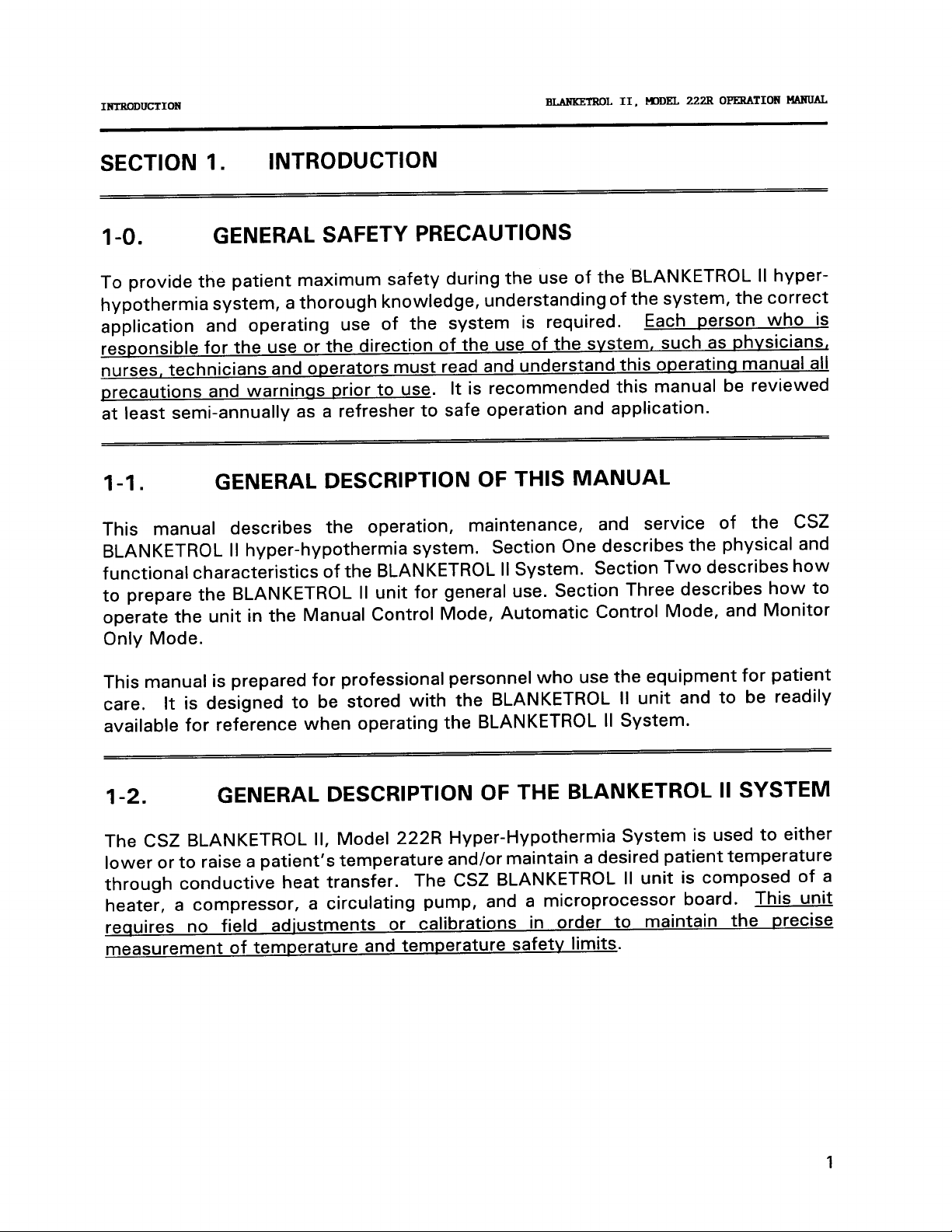
1-o.
To provide the patient maximum safety during the use of the BLANKETROL II
GENERAL SAFETY PRECAUTIONS
hyper-
hypothermia system, a thorough knowledge, understanding of the system, the correct
application and operating use of the system is required. Each person who is
responsible for the use or the direction of the use of the
nurses, technicians and operators must read and understand this
svstem, such as
operatinq
phvsicians,
manual all
precautions and warninss prior to use. It is recommended this manual be reviewed
at least semi-annually as a refresher to safe operation and application.
l-l.
GENERAL DESCRIPTION OF THIS MANUAL
This manual describes the operation, maintenance, and service of the CSZ
BLANKETROL II hyper-hypothermia system. Section One describes the physical and
functional characteristics of the BLANKETROL II System. Section Two describes how
to prepare the BLANKETROL II unit for general use. Section Three describes how to
operate the unit in the Manual Control Mode, Automatic Control Mode, and Monitor
Only Mode.
This manual is prepared for professional personnel who use the equipment for patient
care. It is designed to be stored with the BLANKETROL II unit and to be readily
available for reference when operating the BLANKETROL II System.
l-2.
GENERAL DESCRIPTION OF THE BLANKETROL II SYSTEM
The CSZ BLANKETROL II, Model 222R Hyper-Hypothermia System is used to either
lower or to raise a patient’s temperature and/or maintain a desired patient temperature
through conductive heat transfer.
The CSZ BLANKETROL II unit is composed of a
heater, a compressor, a circulating pump, and a microprocessor board. This unit
requires no field adiustments or calibrations in order to maintain the precise
measurement of temperature and temperature safetv limits.
1
Page 6
INTRODUCTION
B-L
II,
UIDEL
222R
OPERATION
l4ANUAL
l-2. GENERAL DESCRIPTION OF THE BLANKETROL II SYSTEM
(cont’d)
Water is heated or cooled and pumped from the unit to a blanket. The blanket* rests
under and/or on top of the patient and is designed so that the water circulates through
the blanket and returns back to the unit.
If cooled water is circulated through the blanket, the desired effect is to reduce the
patient’s temperature. If warmed water is circulated through the blanket, the desired
effect is to elevate the patient’s temperature.
The BLANKETROL II unit can be set so that it operates based on the temperature of
the circulating water (Manual Control) or it can be set so that it operates based on the
temperature of the patient (Automatic Control).
* The recommended blanket(s) for use is described in Section (I-5.)
1-3. CLINICAL APPLICATIONS
The BLANKETROL II unit is used primarily in hospital Intensive and Coronary Care
Units, in Operating,
Medical/Surgical floors. This hyper-hypothermia system can be used with adult and
pediatric patients to produce normothermia by lowering a patient’s elevated
temperature or raising a patient’s sub-normal temperature. It can also be utilized to
maintain normal body temperature (normothermia) during surgical procedures.
Surgically, this system can be used to produce moderate to profound hypothermia for
such procedures as amputations, cardiopulmonary by-pass surgery, vascular surgery,
and intracranial surgery. Medically, this system can be used to decrease the rate of
circulation, to reduce intracranial pressure, to control cerebral edema, and to reduce
oxygen requirements. This system is also used in the treatment of burns, shock,
cardiac arrest, and gastrointestinal hemorrhage.
Recovery and Emergency Rooms, in Burn Units, and on
Page 7
INTRODUCTION
BLANKETROL II,
mDEL
222R OPERATION MANUAL
l-4.
PHYSICAL DESCRIPTION OF THE BLANKETROL II UNIT
The BLANKETROL II unit is a compact unit with
Dimensions: 17 inches (43.2 cm.) Wide x
x 36 inches (90 cm.) High
Weight: 131 pounds (59.4 kg.)
Cabinet Construction: Powder coated steel
Bottom air discharge.
Storage compartment.
casters.
the following physical features:
17 inches (43.2 cm;) Deep
with plastic top. Dual reservoir.
Molded-in handle. Bumper guards.
Four 5 inch conductive, swivel type
3
Page 8

INTRODUCTION
I-4.1. EXTERNAL FEATURES
BLANKETROL II,
-
FRONT VIEW
HDDEL
222R
OPERATION MANUAL
The external features in Figure (l-l) of the BLANKETROL II unit are described as
follows:
A.
B.
C.
D.
E.
The control panel is composed of pressure sensitive touch switches and
four LED displays. An expanded description of the control panel is
presented in Section (1-4.4.).
The operatinq instructions are printed directly below the control panel.
This layout is designed to increase the operator’s efficient use of the
unit.
The power switch is a bevel rocker switch labeled ON at the top and OFF
at the bottom. The switch lights up green when ON. A circuit breaker
is built into the switch to protect against overload conditions.
storaqe drawer tilts out from the top
The
items such as probes, connector cables,
to provide storage space for
connecting hoses,
the drain
hose, and the Operator’s Manual.
The grille permits air to be drawn into
the unit and pass
over the
condenser. The air is then discharged through the bottom of the unit.
The grille should be kept from being blocked by being cleaned regularly
as described in Section (4-4.) of the Operation/Technical Manual.
F.
G.
H.
I.
The protective bumper quard surrounds the lower edge of the unit and
protects the unit as well as the walls.
Four conductive, swivel casters are specially designed to permit the unit
to move easily and to prevent it from tipping.
The Celsius/Fahrenheit selector switch, abbreviated C/F, is a rocker
switch that permits the operator to select the measurement scale,
Celsius or Fahrenheit, by which the unit functions. Celsius is in the
down position and Fahrenheit is in the up position.
The water fill opening is where the operator pours distilled/sterile water
to fill the reservoir.
Page 9

INTRODDCTION
BLMWZROL
II,-EL
222ROPEWTION
MANIJAL
FIGURE
l-1
BLANKETROL
Ii,
FRONT VIEW
5
Page 10
INTRODUCTION
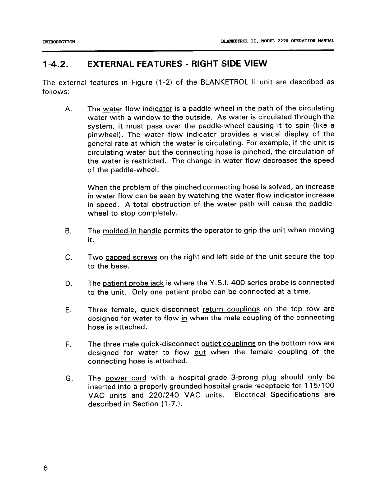
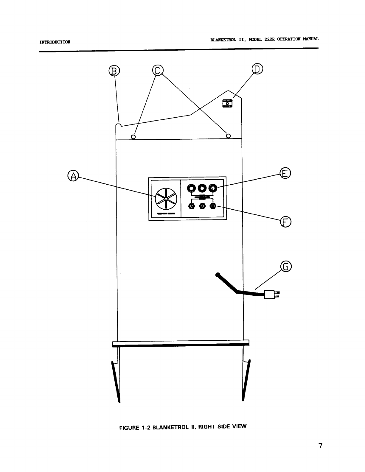
1-4.2.
EXTERNAL FEATURES
BLANKETROL II.
-
RIGHT SIDE VIEW
I%lDEL
222R OPERATION
FlANUAL
The external features in Figure (l-2) of the BLANKETROL II
follows:
A.
The water flow indicator is a paddle-wheel in the
water with a window to the outside. As water is
system, it must pass over the paddle-wheel causing it to spin (like a
pinwheel). The water flow indicator provides a visual display of the
general rate at which the water is circulating. For example, if the unit is
circulating water but the connecting hose is pinched, the circulation of
the water is restricted. The change in water flow decreases the speed
of the paddle-wheel.
When the problem of the pinched connecting hose is solved, an increase
in water flow can be seen by watching the water flow indicator increase
in speed. A total obstruction of the water path will cause the
wheel to stop completely.
B.
The molded-in handle permits the operator to grip the unit when moving
it.
C.
Two capped screws on the right and left side of the unit secure the top
to the base.
unit are described as
path of the circulating
circulated through the
paddle-
D.
E.
F.
G.
The patient probe
iack is where the Y.S.I. 400 series probe is connected
to the unit. Only one patient probe can be connected at a time.
Three female, quick-disconnect return
b
designed for water to flow
when the male coupling of the connecting
couplinns on the top row are
hose is attached.
The three male quick-disconnect outlet
designed for water to flow
out
couplinqs on the bottom row are
when the female coupling of the
connecting hose is attached.
The power cord with a hospital-grade 3-prong plug should
inserted into a properly grounded hospital grade receptacle for 1
VAC units and
220/240
VAC units.
Electrical Specifications are
described in Section (l-7.).
&
15/l
be
00
6
Page 11
1mUCT1ON
222ROPERATION
CIIDEL
BLMKETROL II,
MANUAL
FIGURE 1-2 BLANKETROL II, RIGHT SIDE VIEW
7
Page 12

t-¶lDEL
INTRODUCTION
1-4.3. EXTERNAL FEATURES
BLANKETROL II,
-
REAR VIEW
222R OPERATION MANUAL
The external features in Figure (I-3) of the BLANKETROL II unit are described as
follows:
A.
B.
C.
D.
E.
F.
The maintenance label outlines the periodic checks for the BLANKETROL
II unit.
The specification label outlines the BLANKETROL II unit’s
electrical
requirements.
Two air vents provide air circulation for the microprocessor.
nvlon strap is used to secure and store the coiled power cord when
The
not in use.
The rear enclosure panel secured with four screws provides access to
the interior. The panel is removed to perform maintenance, repair, or
replacement of components.
The serial number label is permanently attached and located along the
bottom of the unit on top of the bumper guard.
8
Page 13

INTRODUCTION
BMNKF3WX
II.FXX.U%
22ZROPERATIONMANUAL
FIGURE 1-3, BLANKETROL II, REAR VIEW
9
Page 14
HDDEL
INTRODUCTION
BLANKETROL
II,
222R OPERATION MANUAL
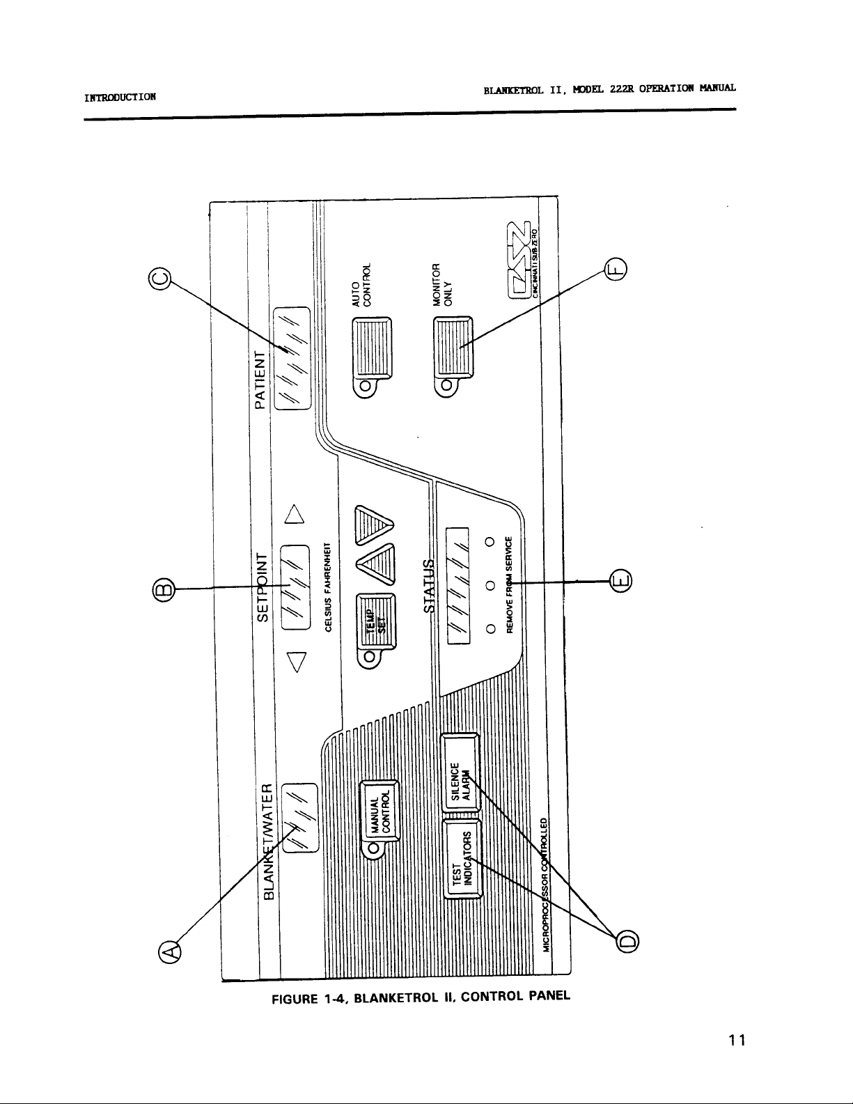
l-4.4. EXPANDED DESCRIPTION OF THE BLANKETROL II
CONTROL PANEL
The control panel as shown in Figure (I-4) is composed of pressure sensitive touch
switches and LED displays.
The control panel is
A.
On the left hand side, the green digital display labeled BLANKET/WATER
shows the actual temperature of the circulating water. The MANUAL
CONTROL switch is used to activate the unit so that operation is based
on the temperature of the circulating water relative to the
temperature.
B.
In the middle, the digital display labeled
temperature of the water or the patient as set by the operator. The
TEMP SET switch and the Up and Down arrow switches are used to set
Setpoint
the
the orange arrow on the right of the
indicator, and the Fahrenheit indicator are only visible under specific
conditions. When visible, each indicator acts as a guide for the operator.
C.
On the right hand side, the orange digital display labeled PATIENT shows
the actual temperature of the patient. The AUTO CONTROL switch is
used to activate the unit so that operation is based on the temperature
of the patient relative to the
layed out as follows:
SETPOINT shows the desired
display. The green arrow on the left of the
Setpoint
Setpoint
temperature.
Setpoint
Setpoint
display,
display, the Celsius
10
D.
E.
F.
The two switches labeled TEST INDICATORS and SILENCE ALARM are
used to confirm that all the indicators on the control panel are working
and to silence the alarm in certain conditions.
The display labeled STATUS reports the status of the unit and/or
indicates changes that the operator should make. The possible status
displays are listed in Section (3-8.). Below the Status display are the
three LED’s colored green, yellow, and red (left to right) that light up
depending on whether the unit is cooling, at setpoint, or heating. A
REMOVE FROM SERVICE indicator is located below the LED and is
visible only if the unit malfunctions in a manner that could be dangerous
to the patient and is not Operator Correctable.
The MONITOR ONLY switch is used to set the unit to monitor the
temperature of the patient without heating, cooling or circulating the
water.
Page 15
AUTO
CONTROL
MONrrcm
ONLY
Page 16
INTRODUCTION
BLANKETROL II,
MJDEL
222R OPERATION MANUAL
l-5.
Operation of the BLANKETROL II unit requires the use of the blanket(s) designed to
circulate warm or cool distilled/sterile water, a connecting hose with quick-disconnect
male and female couplings, and a YSI 400 series thermistor probe (if Automatic
Control Mode is to be utilized). BLANKETROL II System Equipment and accessories
are listed in Figure 3-l.
CSZ offers the widest selection of hyper-hypothermia blankets to serve your needs
providing both reusable and single-patient use blankets. The reusable blanket, the
lightweight
disconnect, error proof male and female couplings. A single-patient use blanket,
MAXI-THERM@, and a reusable connecting hose are also available. All CSZ blankets
offer significantly higher thermal transfer capability than any other brand of
hypothermia blankets.
CSZ also offers a disposable blanket cover, the DISPOSA-COVER’“, that guards
against stains, helps prevent cross-contamination, enhances patient comfort, provides
a moisture barrier, saves on nursing time, and offers greater economy because it
prolongs blanket life and reduces laundry costs.
REQUIRED ACCESSORIES
PLASTIPADB, comes with an integral nine foot extension hose with
quick-
hyper-
Only a Yellow Springs Instrument Company
STERI-PROBE’” single-patient use, should be used with the BLANKETROL II unit. If
a SINGLE-PATIENT probe is used, a REUSABLE CONNECTOR-CABLE is required in
order to connect the disposable probe to the unit. The type of probe may be a
rectal/esophageal or skin surface probe.
Operation of the BLANKETROL II unit requires the use of distilled/sterile water or a
distilled/sterile water-bacteriostatic agent preparation as described in Section (2-4.).
L
NOTE: DO NOT USE DE-IONIZED WATER.
(YSI) 400 Series probe, REUSABLE or
Draining the BLANKETROL II unit requires the use of a drain hose with a female
coupling. This hose is included in the packaging of the unit and can be retained in the
storage compartment of the unit.
l-6.
FUNCTIONAL
DESCRIPTION OF THE BLANKETROL II
SYSTEM
In the Manual Control Mode,
circulating water.
setpoint
temperature. The water circulates through the
The unit either heats or cools the water to reach the desired
the operator sets the desired temperature of the
blanket and either raises or
12
Page 17

INTRODUCTION
BLANKETROL II,
KlDEL
222R OPERATION MANUAL
l-6.
FUNCTIONAL DESCRIPTION OF THE BLANKETROL II
SYSTEM (cont’d)
lowers the temperature of the patient.
be closely monitored. There is no constant relationship between the temperature of
the circulating fluid and the temperature of the patient or the change in temperature
of the patient. In the Automatic Control Mode, the operator sets the desired
temperature of the patient. In addition, the operator must either attach to or insert
into the patient a YSI 400 Series probe.
BLANKETROL II unit. The probe is used to measure the actual temperature of the
patient and this measurement is then compared with the desired
by the unit’s microprocessor. If the actual patient temperature is lower than the
desired patient temperature, the BLANKETROL II unit heats the circulating water so
that the temperature of the patient is elevated to reach the desired Setpoint. At
Setpoint, the unit continues to circulate the water but the heater ceases to operate.
When the patient’s temperature falls outside the
heater/compressor resumes operation, heating/cooling the water until the patient’s
temperature is once again at Setpoint.
If the actual temperature is higher than the desired patient temperature, the
BLANKETROL II unit cools the circulating water so that the temperature of the patient
decreases to the desired
circulate the water, but the compressor stops. When the patient’s temperature falls
outside the
the water until the patient’s temperature is once again at Setpoint.
Setpoint
range, the compressor/heater resumes operation, cooling/heating
Setpoint
temperature.
In this case, the patient’s temperature must
The probe plug is then inserted into the
Setpoint
Setpoint
At Setpoint, the unit continues to
temperature
range, the
In addition, the BLANKETROL II unit can be set to operate in a Monitor Only Mode.
In this mode, the YSI 400 Series probe is attached to or inserted into the patient. The
probe plug is then inserted into the Blanketrol II unit. The operator then sets the
BLANKETROL II unit to monitor and display the patient’s actual temperature. In this
mode, the unit does not heat, cool, or circulate the water.
1-6.1.
The BLANKETROL II heating system consists of an immersion heater, water
temperature control, and three high temperature safety devices. Temperature ranges
are described in Section (l-6.4.).
The immersion heater is located in the circulating reservoir. The water circulating
the reservoir
is operational in the Manual Control or Automatic Control Modes whenever the control
system calls for an increase in the temperature of the circulating water. It is important
to note that the rate of change in the circulating water temperature is not directly pro-
portional to the rate of change in the temperature of the patient.
HEATING SYSTEM
flows around the immersion heater and is warmed. The heating system
in
13
Page 18

INTRODUCTION
BLANKEZTROL
II,
KlDEL
222R OPERATION MANUAL
1-6.2.
COOLING SYSTEM
The BLANKETROL II cooling system is composed of a compressor, a condenser, a
condenser fan, an evaporator coil, water temperature control, solenoid valve, hot gas
bypass valve, and three low temperature safety devices. Temperature ranges are
described in Section (1-6.4.).
The refrigerant of the cooling system flows through the evaporator coil located in the
circulating reservoir.
The water circulating in the reservoir flows over the evaporator
coil and is cooled.
The cooling system is operational in the Manual Control or Automatic Control Modes
whenever the control system calls for a decrease in the temperature of the circulating
water. It is important to note that the rate of change in the circulating water
temperature is not directly proportional to the rate of change in the temperature of the
patient.
CIRCULATING SYSTEM
The BLANKETROL II circulating water system is composed of a magnetically driven
circulating pump, a dual compartment reservoir, a water filter, quick-disconnect
fittings, connecting hose, and hyper-hypothermia blanket(s).
‘/2
The 2 gallon (7
liters) capacity dual compartment reservoir is composed of the circu-
lating reservoir situated under and connected to the replenishing reservoir. When the
operator fills the reservoir with distilled/sterile water
first and holds approximately
%
gallon (1.9 liters) of water. The remaining 1
*,
the circulating reservoir fills
%
gallons
(5.6 liters) are held in the replenishing reservoir. The water moves from the
replenishing reservoir to the circulating reservoir by gravity drain as needed.
The circulating water flows over and around the heating/cooling element located in
the circulating reservoir. The heated or cooled water then flows out of the reservoir
to the circulating pump, through the pump housing, through connecting hoses over
a water temperature sensor to the hyper-hypothermia blanket(s). The water circulates
through the blanket(s) and returns to the unit. The water then passes through the
water flow indicator, through the water filter and returns to the circulating reservoir
to be reheated or
retooled
and then recycled.
In addition, the circulating reservoir contains a low water level sensor which shuts
down the unit and sounds the alarm if the water level drops below a preset amount.
The unit becomes operational again after the water level is restored to normal.
*
Alternate water preparations are described in Section (2-4.)
NOTE: DO NOT USE DE-IONIZED WATER.
14
Page 19

INTRODUCTION
BLANKETROL II,
MODEL
222R
OE'ERATION
l-6.4. TEMPERATURE SAFETY CONTROL SYSTEM
The BLANKETROL II unit is designed to carefully measure and control the temperature
of the circulating water. The unit is engineered so that when the temperature of the
circulating water reaches the desired
setpoint
heating and cooling the water in order to maintain the
is designed not to exceed or fall below the desired temperature.
As a safety precaution, the BLANKETROL II unit has three high temperature safety
devices and three low temperature safety devices. Figure (I-5.) summarizes the high
and low temperature limits.
Each safety device continuously monitors the temperature of the circulating water and
almost any possible failure is protected by a back-up system.
precaution, if the water temperature sensor itself should fail, the unit shuts down and
indicates REMOVE FROM SERVICE. With this safety design, both the patient and the
unit are protected from injury or damage caused by extreme temperatures.
temperature, the unit operates between
setpoint
temperature. The unit
As an additional
MtlNUAL
At the same time, the operator must regularly monitor the patient whenever
hypothermia therapy is used.
hyper-
15
Page 20

INTRODUCTION
BLANKETROL
II, MODEL 222R OPERATION MANUAL
SAFETY CONTROLS FOR PROTECTION FROM HIGH TEMPERATURE
OF)
Circulating water reaches
shuts off heater.
f
42OC
.5OC
(107.6OF
+
microprocessor board
1
Circulating water reaches
44.6OC
1
+
(112OF
OC
+
2O)F, safety device shuts off
heater, status display flashes “HI TEMP” and the microprocessor board beeper is
sounded.
4OF), back-up safety device shuts
+
Circulating water reaches
46OC
+
2OC
(115OF
off the unit and indicates REMOVE FROM SERVICE, HI LIMIT.
SAFETY CONTROLS FOR PROTECTION FROM LOW TEMPERATURE
OF),
+
Circulating water reaches
+
4OC
(39.2OF
1
.5OC
off cooling system.
2”F),
f
Circulating water reaches
3OC
OC
1
+
(37OF
off cooling solenoid and indicates “LOW TEMP.”
Circulating water reaches 1
+
OC
+
1 (34OF .5OC
off the unit and indicates REMOVE FROM SERVICE, LOW LIMIT.
microprocessor board shuts
microprocessor board shuts
OF),
back-up safety device shuts
16
FIGURE
(I
-5) TEMPERATURE SAFETY LIMITS
Page 21

INTRODUCTION
BLANKETROL II,
KlDEL
222R OPERATION MANUAL
1-7.
SPECIFICATIONS OF THE BLANKETROL II UNIT
BLANKETROL
PHYSICAL
Dimensions:
Weight:
17”D
(43.18cm.W
cm.D x
134 Ibs.
91.44cm.H)
(60.3kg.)
36”H
x 17”W x
x 43.18
Cabinet Construction:
Epoxy-coated steel with plastic
top. Dual reservoir. Bottom air
discharge.
Molded-in handle.
Bumper guard. Storage
compartment. Four 5”
360°
conductive,
swivel-type
casters.
CONTROL SYSTEM
Microprocessor controlled,
OF
“ON-OFF” switch,
OC
or
Switch,
Digital LED Read Outs, 6 Alarm
Indications, 4 Mode Indications.
Controller Range:
42OC
to
Water Temp.:
Patient Temp.:
4OC
(39.2OF
to
to
4o”c3o”c
104OF)(86OF to
Display Accuracy:
f
Water Temp.
Patient Temp.
+
.25OC
(k
Display Range:
5o”c
-
Water Temp.
Patient Temp.
Display Type:
o”c
122OF)
-
(32OF
43.5OC
-
IOOC
-
50°F
Digital/Color-Coded
1
IOOF
Temp.Settings:
(.2OF)
OC
.1
Water Temp.
:
Patient Temp.:
Patient Probe Jacks:
Probe Type:
(.2OF)
OC
.I
One
YSI Series 400
Lighted
107.6OF)
l°F)(+
.5OC
.5OF)
II
MODEL 222R FEATURES
THERMAL SYSTEM
Compressor:
Heater:
NOTE: Water cooling rate is approx-
imately
heating rate is approximately 3
per minute.
4OC
CIRCULATING SYSTEM
Dual Reservoirs, 2 gallon (7% liters)
total capacity. Error proof,
disconnect couplings. All circulating
components are non-corrosive.
ELECTRICAL SYSTEM
Electrical Characteristics:
(Std.)
(Opt.)
Power Cord:
Leakage Current: Under 100
Circuit Breaker:
SAFETY SYSTEM
Maximum High Control Setting:
42OC
Primary High:
Secondary High Independent Backup:
2OC
46OC
+
Maximum Low Control Setting:
4OC
Primary Low:
1°C
_+
3OC
Secondary Low Independent Backup:
.5OC
+
1°C
l/3
HP (Copeland)
800 Watts
(8°F)
per minute and the
115V,60Hz.,
220V,50Hz.,
16/3
SJT,
Hospital grade plug
In Power Switch
(107.6OF)
l°C
f
44.6OC
(112OF
(115OF
(39.2OF)
(37OF
(34OF
(6O
OC
quick-
9.6 Amps
5 Amps
pa
2OF)
f
+
4OF)
2O)F
f
l°F)
f
F)
17
Page 22

INTRODUCTION
BIANKETROL
II,
mDEL
222R OPERATION MANUAL
l-7.
SPECIFICATIONS OF THE BLANKETROL II UNIT
BLANKETROL II MODEL 222R FEATURES
Defective or Dislodged Probe Alarm:
&
Audible
Primary
&
Secondary High and
Visual
Secondary Low Limit Failure Alarm:
&
Audible
Low Water Alarm:
Visual
Audible
&
Visual
Defective Water Temp Sensor:
Audible & Visual
Water Flow Indicator: Visual
Optional:
Low Flow Alarm Kit
Audible & Visual
(cont’d)
2 yr.
years
WARRANTY
parts (compressor-additional 3
pro-rated)
18
Page 23

GENEFML
PREPARATION OF THE
BIANKETW
SYSTm
L
II
B-L
II, MODEL
222ROPERATIONMNUAL
SECTION 2.
GENERAL PREPARATION OF THE BLANKETROL II
SYSTEM
2-l.
This section describes the procedures to prepare the BLANKETROL II unit for general
use. This entails unpacking the shipment, arranging all the equipment the first time,
and completing a test routine.
water-bacteriocidal agent preparations, standard safety precautions, and patient
preparation/bedside care when using the hyper-hypothermia blanket(s).
2-2.
Inside the packing carton, the BLANKETROL II unit is covered with a plastic wrap and
is cushioned with foam padding on the top. Corrugated cardboard protectors on the
top, bottom, and four corners. A large envelope with the manuals, warranty card, and
the drain hose is enclosed in the storage compartment of the unit. BE SURE TO
COMPLETE AND RETURN THE WARRANTY CARD.
INTRODUCTION
This section also outlines the optional distilled/sterile
UNPACKING THE SHIPMENT
During the unpacking process, look carefully for signs of shipping damage. If any
damage is found, notify the transportation company immediately and file a claim. The
transportation company is responsible for the shipment after it leaves the factory. If
problems other than shipping damage are found, notify your Cincinnati Sub-Zero
representative or the Cincinnati Sub-Zero office at l-800-989-7373.
2-3. FIRST TIME SET-UP/SYSTEM TEST ROUTINE
This section describes the tasks necessary to inspect and arrange the equipment for
the first time after unpacking and describes a System Test Routine to check out the
control panel.
The System Test Routine can also be used to teach operators unfamiliar with the
equipment how to use the unit.
The following tasks should be completed prior to assigning the unit for floor use:
2-3.1.
a.
INSPECTING AND ARRANGING THE EQUIPMENT
Place the BLANKETROL II unit in an uncluttered work space that is
accessible to the correct power source. Position the unit so that the
control panel faces the operator.
19
Page 24

BLANKFaTROL
TEE
GENERAL PREPARATION OF
II
SYSTEM
BLANKETROL II,
MlDEL
222R OPERATION
MAAUAL
2-3.1.
b.
C.
d.
e.
INSPECTING AND ARRANGING THE EQUIPMENT (cont’d)
If the unit was shipped on its side, permit the unit to rest in an upright
position for approximately one hour before operating.
Review Section (I-4.) to identify the features of the BLANKETROL II
unit.
Collect and arrange the following equipment and supplies:
1.
2. Connecting hose with quick-disconnect fittings if using disposable
3. Distilled/sterile water
Visually inspect the BLANKETROL II unit to determine that there are no
missing parts, unusual dents or punctures.
Hyper-hypothermia blanket(s) described in Section (l-5.)
blanket(s)
a
the distilled/sterile water-bacteriocidal
preparation described in Section (2-4.). DO NOT USE ALCOHOL
or DE-IONIZED WATER. The reservoir holds approximately 2
(7%
gallons
unit requires approximately
liters). Each empty blanket that is connected to the
%
gallon (1.9 liters) of water.
f.
h.
Examine the power cord for cuts or exposed wires and the power plug
(3-prong
for
115/l
00 VAC units, appropriate plug for
220/240
VAC
units) for bent or missing prongs.
Lift the lid of the water fill opening and gradually pour approximately 2
gallons (7
%
liters) of distilled/sterile water
a
the distilled/sterile
water-
bacteriostatic agent preparation into the reservoir. Stop pouring when
the water reaches the strainer visible at the bottom of the water fill
opening.
Connect the blanket(s) to the BLANKETROL II unit by attaching the
quick-disconnect female coupling of the connecting hose to a male outlet
coupling (on the bottom row) of the unit.
Attach the male
quick-
disconnect coupling of the connecting hose to a female return coupling
(on the top row) of the unit.
Each blanket must be connected to one
outlet and one return.
20
Page 25

GENERAL PREPARATION OF THE
LtunsmOL II
B
SYSTm
BLANKETROL
II,KlDEL222ROPEMTIONMANlJAL
2-3.1.
INSPECTING AND ARRANGING THE EQUIPMENT
(cont’d)
To attach the couplings:
Grasp the female coupling of the connecting hose
1.
Slide the collar back towards the hose
2.
Push the female coupling over a male coupling of the unit
3.
Allow the collar to SNAP into place and return to its original
4.
position
Gently pull on the connecting hose to assure a positive connection
5.
Next, push back the collar of a female return hose on the unit
6.
with one hand
With the other hand, insert the male coupling of the connecting
7.
hose
Release the collar of the female return coupling
8.
Push the male coupling until it SNAPS into position
9.
10.
i.
Check that the blanket is laying flat and that the connecting hose to the
Gently pull the connecting hose to assure a positive connection
unit is not twisted or pinched.
j.
Check that the power switch of the unit is OFF.
k.
Insert the 3-prong plug for 1
for
220/240
VAC units) into a properly grounded hospital grade
15/l
00 VAC units (appropriate ground plug
receptacle.
WARNING: DO NOT BY-PASS THE GROUND PLUG. ELECTRICAL HAZARDS
MAY RESULT.
2-3.2. COMPLETING A SYSTEM TEST ROUTINE
After arranging the equipment as described in Section
(2-3.1.),
Test Routine which describes what switches to press and the changes to observe.
a.
Make sure that the power switch is in the “ON” position.
1.
2.
3.
The switch lights up green.
The microprocessor board goes through self-test.
The status display in the center of the control panel flashes CK
SETPT.
4. The Celsius
or Fahrenheit indicator lights up.
complete this System
21
Page 26

H3DEL
GENERAL
PREPARATION OF TEE B
II
SYSTm B-L II, LANZTROL
222R OPERATION MANUAL
2-3.2. COMPLETING A SYSTEM TEST ROUTINE (cont’d)
If any of the above are not observed, consult the Troubleshooting Guide in Section
(6.) of the Operation/Technical Manual. If they are observed, continue with the test
routine.
b.
Press and hold the TEST INDICATOR switch.
1.
The yellow and green arrow, the LED’s in the corner of the
switches, the Celsius/Fahrenheit indicator, and the Remove From
Service indicator flash on and then off.
2. Then, all the displays flash.
The operator should note that all the displays and indicators do light up. If they do not
light up, consult the Troubleshooting Guide in Section (6.) of the Operation/Technical
Manual. If they do light up, continue with the test routine. The Status display
continues to flash CK SETPT.
C.
Press the TEMP SET switch.
1.
2.
3.
4.
The microprocessor board beeps.
The LED in the corner of the switch lights up.
The Status display shows SET TEMP.
The
Setpoint
display shows
a
37OC
98.6OF
(depending upon the
position of the Celsius/Fahrenheit indicator switch). Each
time the operator presses the TEMP SET switch after just having
plugged in the
unit, the
Setpoint
display shows
98.6OF.
a
37OC
22
d.
e.
Change the position
front of the unit).
The
1.
2.
Setpoint
98.6OF
to
The Celsius/Fahrenheit indicator changes from Celsius to
Fahrenheit (or from Fahrenheit to Celsius).
Press
1.
2.
3.
4.
5.
6.
the MONITOR ONLY switch.
The microprocessor board beeps.
The LED in the corner of the switch lights up.
Celsius/Fahrenheit indicator is lit.
The Status display shows MONITOR.
Setpoint
The
For
this
test routine, the Patient display is blank because the
probe is not inserted in the probe jack.
of the Celsius/Fahrenheit Selector switch (on the
display changes from
98.6OF
37OC).
display is blank.
(or from37OC to
Page 27

GENERAL PREPARATION OF TEE BLANKETROL II
SYSTEM
BLANKETROL II,
HDDEL
222R
OPERATION MANUAL
2-3.2.
NOTE:
COMPLETING A SYSTEM TEST ROUTINE (cont’d)
f. Press the TEMP SET switch.
The microprocessor board beeps.
The LED in the corner of the switch lights up.
The Celsius/Fahrenheit indicator is lit.
The
Setpoint
display shows
The Status display shows SET TEMP.
IN ORDER TO CHANGE FROM ONE MODE TO ANOTHER, THE
TEMP
CAN BE SET. For example; to change from Monitor Only Mode to
Manual Control Mode, the Temp Set switch must be pressed first
before the Manual Control Mode switch can be pressed.
1.
2.
3.
4.
5.
6.
7.
8.
9.
SET SWITCH MUST BE PRESSED BEFORE THE NEXT MODE
The microprocessor board beeps.
The LED in the corner of the switch lights up.
The Celsius/Fahrenheit indicator is lit.
Setpoint
The
The
Blanket/Water display shows the temperature of the water in
display shows a temperature reading.
the reservoir.
The green arrow (left of the
The Status display shows COOLING, AT SETPT
depending upon the relationship of the water in the reservoir to
the Setpoint.
A LED corresponding to the Status display lights up green for
COOLING, yellow for AT SETPT, or red for HEATING.
The pump is activated; there is a soft hum.
The heater or compressor may be activated.
The Water Flow indicator on the right side panel begins to move.
The water moves from the unit through the blanket and returns to
the unit.
9.
1.
2.
3.
4.
5.
Press the MANUAL CONTROL switch.
10.
11.
37OC or
Setpoint
98.6OF.
display) lights up.
a
HEATING,
If in the process of filling the blankets the water is no longer visible in the bottom of
the water fill opening, more distilled/sterile water should be added.
23
Page 28

BLANKETFUlL
II GENERAL PREPARATION OF TEE
SYSm
BLANKETROL II,
HDDEL
222R OPERATION MANUAL
2-3.2.
COMPLETING A SYSTEM TEST ROUTINE (cont’d)
If at any time the water falls below a preset limit, the Low Water sensor is activated
and the Status display flashes LO WATER and the alarm sounds. The unit shuts down
and the operator cannot proceed until this is corrected as described in Section (3-8.).
h.
Check the blanket for leaks. If a leak is found, the blanket cannot be
used. The repair of reusable blankets is described in
Set
(4-6) of the
Operation/Technical Manual.
i.
Check the couplings at the unit and at the blanket for positive
connection.
j.
Press the TEMP SET switch
1.
The microprocessor board beeps.
2. The LED in the corner of the switch lights up.
3. The
green arrow left of the
Setpoint
display goes out.
4. The Blanket/Water display goes blank.
5. The Celsius/Fahrenheit indicator is lit.
6. The
7. The
Status display shows SET TEMP.
pump shuts down, the heating/cooling stops.
I.
k.
When the TEMP SET switch is pressed, the operating mode (e.g. Manual
a
Control Mode, Automatic Control Mode
Monitor Only Mode) is
cancelled. The operator is once again at the beginning of the mode
selection procedure.
Press the Up arrow next to the TEMP SET switch.
1.
The microprocessor board beeps each time it
2. The
Setpoint
display changes; the numbers move up the scale.
is pressed.
The longer the switch is pressed the faster the digits change.
When the switch is released and repressed, the digits once again
change slowly and then increase in speed. The highest setting is
or
107.6OF.
42OC
Press the Down arrow next to the TEMP SET switch.
1.
2. The
The microprocessor board beeps each time it is pressed.
Setpoint
display changes; the numbers move down the scale.
The longer the switch is pressed the faster the digits change.
When the switch is released and repressed, the digits once again
change slowly and then increase in speed. The lowest setting is
4OC or
39.2OF.
24
Page 29

2228
TH!?a
BGENERAL PREPARATION OF
LtimxmOL
IISYSTm
B-L
II,
UJDEL
OPERATION
2-3.2. COMPLETING A SYSTEM TEST ROUTINE (cont’d)
klANUAL
m.
n.
0.
Press the Up arrow or Down arrow so that the
-
a number between
display to show
30°C
32.3OC
or
40°C
-
9OoF.
(86OF
104°F). For example, set the
SETPOINT display shows
Insert a YSI 400 series probe jack on the side of the unit.
Press the AUTO CONTROL switch.
1.
2.
3.
Setpoint
The
The alarm sounds.
The Status display flashes CK PROBE.
display goes blank.
The alarm sounds because the patient probe, as held by the operator in the open air,
30°C
for this test routine, detects a reading below
(86°F). The unit will not operate
in the Auto Control Mode unless the probe is properly placed on a patient and reading
above
30°C
Pm
(86°F).
Press the SILENCE ALARM switch.
1.
2.
The alarm stops.
The Status display continues to flash CK PROBE.
The Operator has 5 minutes to correct the problem. In an actual
situation, the operator would check the probe and then continue
operation.
Press
1.
2.
3.
4.
r.
Press
shows a number less than
the TEMP SET switch.
The microprocessor board beeps.
The LED in the corner of the switch lights up.
The
Setpoint
display shows a temperature reading.
The Status display shows SET TEMP.
the Up arrow or the Down arrow so that the
30°C
For example, set the display to show 41
S. Press the AUTO CONTROL switch.
2.
1.
Setpoint
The
The Status display flashes CK SETPT.
display goes blank.
Setpoint
or
106°F.
OC
40°C
display
(104OF).
(86OF) or greater than
25
Page 30

BIANKETROL
II GENERAL PREPARATION OF TEE
SYSTM
BLANKETROL II,
HODEL
222R OPERATION MANUAL
2-3.2.
COMPLETING A SYSTEM TEST ROUTINE (cont’d)
The display flashes because the
Setpoint
Automatic Control Mode temperature range of
104°F).
Setpoint
t.
Press the TEMP SET switch
1.
2.
3.
The unit will not operate in Automatic Control Mode unless the
display shows a number within the range.
The microprocessor board beeps.
The LED in the corner of the switch lights up.
The
Setpoint
display shows a temperature reading.
4. The Status display shows SET TEMP.
U.
Press the MANUAL CONTROL switch.
The microprocessor board beeps.
1.
The LED in the corner of the switch lights up.
2.
The green arrow left of the
3.
4.
The Celsius/Fahrenheit indicator is lit.
The Blanket/Water display shows the temperature of the water in
5.
Setpoint
the reservoir.
The Patient display shows the temperature reading of the probe,
6.
as it is held by the operator, if the probe reading is in the range of
-
-43.5OC
7.
The
Setpoint
8.
The Status display shows COOLING, AT SETPT, or HEATING
(50°F
IOOC
display shows a temperature reading.
110°F).
depending upon the relationship of the water in the reservoir to
the Setpoint.
A LED corresponding to the Status display lights up: green for
9.
COOLING, yellow for AT SETPT, or red for HEATING.
IO.
. 11.
12.
The pump is activated; there is a soft hum.
The heater or compressor may be activated.
The water flow indicator on the right side panel begins to move.
temperature is outside the
30°C-40°C
(86OF-
display lights up.
This step is included to show that the patient display lights up when the probe is
inserted and the unit is in the Manual Control Mode as well as when the unit operates
in the Automatic Control Mode.
V.
To complete this test routine, turn the power switch OFF.
The control panel goes blank.
1.
The green light of the power switch goes out.
2.
26
Page 31

GENF3AL
PREPARATION OF
BLANKETROL II
SYSTENTHE
B-L
II,
kl3DEL
222R OPERATION
2-3.2. COMPLETING A SYSTEM TEST ROUTINE (cont’d)
If the power switch is set ON again without having unplugged the unit
and the Temp Set switch is pressed, the
temperature that was on the display prior to the operator turning the unit
off.
W. Remove the probe from the probe jack, loosely coil it and place it in the
storage drawer in front of the unit.
In an actual situation, the probe is
cleaned as described in Section (4-7.) of the Operation/Technical Manual
before it is stored.
Setpoint
display shows the
MNUAL
X.
Disconnect the power cord from the power source, loosely coil it and
attach it to the back panel using the nylon strap.
-
Y*
For reusable
PLASTIPAD
-
blankets, disconnect the connecting hose
from the unit. Loosely coil the hose lengthwise in the center of the
l/3
blanket. Fold the blanket lengthwise into the center,
side and
l/3
from the right side.
The water can remain in the blanket
from the left
and in the unit between periods of use.
For single-use MAXI-THERM blankets, follow the instructions packaged
with the blanket. The water should be changed monthly
as described in
Section (4-2.) of the Operation/Technical Manual.
The BLANKETROL II System; unit, connecting hose, blanket(s), and
probe are now
ready for patient use.
2-4.
SUGGESTIONS FOR PROTECTING THE RESERVOIR FROM
BACTERIA AND FOR DECONTAMINATION GUIDELINES
If distilled/sterile water is used and changed monthly, there should be no problem with
bacteria forming in the reservoir or blanket(s). If hospital procedures require the use
of a bacteriostatic or bactericidal agent, we suggest Hospital-Approved
Agents which are non-acidic and non-foaming.
Bacteriocidal
NOTE:
DO NOT USE DE-IONIZED WATER. THE MAJORITY OF
DE-IONIZERS DO NOT MAINTAIN A NEUTRAL PH OF 7. IF THE
DE-IONIZED WATER IS ACIDIC, IT WILL CAUSE A BATTERY
EFFECT AND THE COPPER REFRIGERATION LINE WILL BEGIN TO
DETERIORATE AND CAUSE A LEAK IN THE REFRIGERATION
SYSTEM.
27
Page 32

PREPARATION
SYSTm
OF TBE GENERAL
B-
L II
BLMKEXROL II,
MDDEL
222R OPERATION MANUAL
2-4.
SUGGESTIONS FOR PROTECTING THE RESERVOIR
FROM BACTERIA AND FOR DECONTAMINATION
GUIDELINES
SUGGESTED DECONTAMINATION GUIDELINES FOR CINCINNATI SUB-ZERO
EQUIPMENT
(Developed in conjunction with the risk management department
at the Shriners Burn Institute in Cincinnati, Ohio)
Decontamination in the Healthcare environment is of the utmost concern with today’s
array of potential infectious diseases. Cincinnati Sub-Zero has always been aware of
these concerns in conjunction with the water reservoirs and circulatory systems of
a
CSZ equipment.
For this reason,
schedule for flushing and cleaning the water system in an effort to inhibit the growth
of bacteria and fungi.
The following decontamination procedure was developed to effectively rid the water
system of all bacteria and not damage any of the internal components of the
M
equipment.
Steps should be followed as closely as possible. This decontamination
procedure should be conducted every three (3) months.
CSZ equipment have a suggested monthly
The Procedure:
a.
b.
CAUTION:
Drain the water from the reservoir as described in Section (4-2.
Flush the unit three (3) times per the following procedure.
1.
Add one (1) ounce (30 cc) of household bleach
hypochlorite) to the empty water reservoir.
IT IS STRONGLY SUGGESTED THAT APPROPRIATE EYE
PROTECTION AND GLOVES BE WORN WHEN HANDLING AND
USING BLEACH. WEARING AN APRON IS ALSO SUGGESTED TO
PROTECT CLOTHING.
2.
3. Turn the unit on and circulate per the chart below.
Fill the reservoir with warm tap water.
1).
sodium
(
28
Page 33

GENIXAL
PREPARATION OF THE
BLANKETROL
II
SYSTM
BLANKETROL II,
HDDEL
222R
OPEMTION
t4ANUAL
2-4.
C.
d.
e.
f.
SUGGESTIONS FOR PROTECTING THE RESERVOIR
FROM BACTERIA AND FOR DECONTAMINATION
GUIDELINES
UNIT
Blanketrol II
4.
Rinse the unit three (3) times as described in (b) except to omit the
household bleach (sodium hypochlorite).
After the third rinse, drain the unit and add 32 ounces
distilled water to the water reservoir and circulate.
Check the water with “Fat-Chek” Ph strips or other appropriate test
method for detecting bleach. If bleach is detected, repeat steps
Once
Propylene Glycol to the water reservoir per the following chart:
Drain the unit after each flush.
no
bleach is detected, add the appropriate amount of U.S.P. Grade
(cont’d)
MODE
Manual
TEMPERATURE DURATION
lOOoF
5 Min.
(1
liter) of sterile
(c,d,e).
9.
h.
i.
UNIT
Blanketrol II
U.S.P. GRADE PROPYLENE GLYCOL PER UNIT
16 oz. (500 cc)
Continue to fill the water reservoir with sterile distilled water.
Document the maintenance of the unit.
The unit is now ready to be placed back in service.
29
Page 34

GENERAL PREPARATION OF TBE B
LMKETROL II
SYSTR4
BLANKETRDL
II,
KlDEL
222R OPERATION MANUAL
2-5.
UNIT AND PATIENT RELATED PRECAUTIONS
This unit requires both water and electricity to operate.
WARNING: ANYTIME WATER IS FOUND LEAKING INTO OR AROUND THE
UNIT, THE CONNECTING HOSE, AND/OR BLANKET, TURN THE
UNIT OFF, DISCONNECT THE POWER CORD FROM ITS POWER
SOURCE, AND CORRECT THE PROBLEM BEFORE PROCEEDING.
CAUTION: EXERCISE EXTREME CAUTION IF THE UNIT IS USED FOR
PATIENTS WHO ARE ELECTRICALLY SUSCEPTIBLE (PROBE,
CATHETER, OR ELECTRODES DIRECTLY CONNECTED TO THE
HEART).
1.
Test for leakage current prior to general floor use. See Section (5-18.) of
the Operation/Technical Manual.
2.
Anytime a repair is made, make sure that the power cord is disconnected
from the power source before disassembly.
The repair and servicing of the BLANKETROL II unit as described
3.
in Section (5.). requires no special tools.
However, only persons with the
proper skills and knowledge should undertake any repairs, servicing or
maintenance of the unit.
The high and low temperature safety devices protect the patient and the unit
4.
from injury or damage that can be caused by temperature extremes. At the
same time, a patient should be monitored closely when hyper-hypothermia
treatment is used.
Anytime the unit sounds an alarm, the operator should immediately check
5.
the Status display and act accordingly, e.g., add water, remove from
service, check the probe.
The BLANKETROL II unit is equipped with a circuit breaker in the ON/OFF
6.
power switch to protect against current overload.
30
Page 35

GEXERAL
PREPARATION OF TEE B
MNKETROL II
srsm
BLANKETROL II,
HlDEL
222R OPERATION
M4NUAL
2-6.
PATIENT PREPARATION AND BEDSIDE CARE
Effective use of the BLANKETROL II system must include proper patient care prior to
and while using the hyper-hypothermia blanket(s). Standard nursing procedures,
before using the blanket(s), include the following tasks:
CAUTION: THE DESIRED
SETPOINT
TEMPERATURE SHOULD BE SET ONLY AS
PRESCRIBED AND UNDER THE ORDER OF A PHYSICIAN.
a.
b.
C.
d.
e.
A base line recording should be made of vital signs, level of consciousness
and responsiveness.
Lanolin or a lanolin/cold-cream mixture may be applied to the patient’s
exposed skin.
Protective wraps may be used to cover patient’s hands and feet.
As ordered, a retention urinary catheter may be inserted to evaluate renal
function and renal output.
As ordered, an intravenous infusion may be started.
f.
As ordered,
drv
A
sheet or DISPOSA-COVER should be placed between the
preinduction medications may be administered.
hypothermia blanket and the patient.
Standard nursing procedures while using a hyper-hypothermia blanket include the
following tasks:
a.
Patient’s vital signs should be recorded and evaluated frequently. Operating
room, temperature sensitive and pediatric patients may deviate from normal
responses to external applications of heat and cold.
Patient core
temperature and the condition of the skin in contact with the blanket and
blanket water temperature should be checked every twenty minutes.
Operating room, temperature sensitive and pediatric patients should be
checked more frequently. Notify the physician if the patient’s core
temperature does not reach the prescribed temperature in the time
prescribed or deviates from the prescribed temperature range.
hyper-
31
Page 36

222R
THE
BLANKETROL II GENERAL PREPARATION OF
SYSTM
BLANKEZTROL
II,
HJDEL
OPERATION MANUAL
2-6. PATIENT PREPARATION AND BEDSIDE CARE (cont’d)
b.
C.
d.
e.
f.
9.
The position and the placement of the probe should be inspected regularly.
Also, the BLANKETROL II unit activates an alarm when the patient probe
110°F).
-
registers outside the range of
30°C
43.5OC
-
(86OF
Level of consciousness, strength of extremities, changes in cardiac rate,
changes in cardiac rhythms, pupil size, and response should be observed and
recorded.
Changes in skin color, edema, inflammation, or indications of pressure,
especially over bony prominences, should be noted and treated as ordered.
Prevent prolonged tissue pressure and shearing forces over bony
prominences.
The patient should be turned and properly positioned frequentlv.
As ordered, medications to prevent shivering may be administered.
The patient’s nasal passages, air-way and oral cavity should be kept free of
secretions and/or mucus build-up.
WARNING: THE PATIENT SHOULD BE CONSTANTLY ATTENDED. THE MISUSE
OF HYPER-HYPOTHERMIA EQUIPMENT PRESENTS THE POTENTIAL
FOR PATIENT INJURY.
CAUTION:
THE APPLICATION OF HEATING OR COOLING MAY EFFECT THE
TOXICITY OF SOLUTION. PREP SOLUTIONS HAVE BEEN
REPORTED TO INJURE THE SKIN WHEN ALLOWED TO REMAIN
BETWEEN PATIENT AND A WATER-CIRCULATING HEATING
BLANKET DURING PROLONGED PROCEDURES. -- KEEP THE AREA
BETWEEN THE PATIENT AND THE BLANKET
DRY.
32
Page 37

OPERATING TEE
B-TROL
II UNIT
BLANKETROL II.
KIDEL
222R OPERATION
FM.NUAL
SECTION 3
OPERATING THE BLANKETROL II SYSTEM
3-l. INTRODUCTION
This section describes how to operate the BLANKETROL II unit in order to control
your patient’s temperature. First, collect the equipment and prepare the patient.
Second, decide which mode of operation to use. Third, set the appropriate controls;
Automatic Control Mode, Manual Control Mode, or Monitor Only Mode.
3-2.
a.
ARRANGING THE SYSTEM COMPONENTS
Collect all supplies and equipment.
1.
2.
3.
4. Connecting hose, if using MAXI-THERM disposable blanket(s)
5.
6. Connector cable (if using disposable probes)
7. Distilled/sterile water
BLANKETROL II unit
Hyper-hypothermia blanket(s)
Dry sheet, bath blanket or DISPOSA-COVER
YSI 400 series probe
b.
C.
d.
e.
f.
g.
Place the BLANKETROL II unit in the patient area, accessible to the
correct power source.
Review Section (l-4.) that outlines the features of the unit and control
panel.
Check the level of distilled/sterile water in the reservoir. To do so, lift
the cover of the water fill opening and the water should be visible,
touching the strainer.
If needed, carefully add distilled/sterile water. In
addition, if the water falls below a preset level, the alarm sounds and the
Status display flashes LO WATER. The operator cannot proceed until
this is corrected as described in Section (3-8.).
Check that the power switch is in the OFF position.
Inspect the power plug
plug for
220/240
VAC units) for bent or missing prongs.
Insert the 3-prong plug for
220/240
VAC units) into a properly grounded hospital grade receptacle.
(3-prong for
115/l
115/l
00 VAC units, appropriate
00 VAC (appropriate ground plug for
33
Page 38

OPFXATING
TEE BLANKETROL II
UNIT
BIANKETROL
II,
tWDEL
2228
OPERATION MANUAL
3-2.
ARRANGING THE SYSTEM COMPONENTS (cont’d)
WARNING: DO NOT BY-PASS THE GROUND PLUG; ELECTRICAL HAZARDS
MAY RESULT.
h.
i.
j.
k.
I.
m.
Lay the hyper-hypothermia blanket flat with the hose arranged without
kinks towards the unit.
If the blanket is already filled, check that there are no leaks.
Cover the blanket with a dry sheet, bath blanket or DISPOSA-COVER.
Connect the blanket to the BLANKETROL II unit as described
in Section
(2-3.1.),
Step (h).
If a MAXI-THERM single-patient use hyper-hypothermia blanket is used,
connect the color coded couplings of the connecting hose to the blanket
as described in the instructions packaged with each blanket.
Check that the blanket is flat and the connecting hose is not twisted or
pinched.
n.
0.
P-
The hyper-hypothermia blanket may be
positioning the patient.
To do so, operate the unit in Manual Control
precooled or prewarmed before
Mode for a few minutes.
Place the patient on the hyper-hypothermia blanket.
If the patient’s temperature is to be monitored as required in Automatic
Control Mode or Monitor Only Mode, insert into or attach to the patient
a YSI 400 Series probe.
1.
A rectal probe is inserted into the rectum and secured with tape
to the leg of the patient.
2.
The diaphragm of a skin probe is taped to the patient, usually
under the patient’s arm or on the chest.
3.
The esophageal probe is inserted into the patient. It is often
preferred that the patient is comatose or under anesthesia.
The probe should be inspected periodically to insure that it is not
dislodged or impacted. The BLANKETROL II unit sounds an alarm
30°C
when the reading from the probe falls below
(86°F). It is
34
Page 39

OPERATING TEE BLANKETROL II
UNIT
B-L II,
HDDEL
222R OPERATION MANUAL
3-2
ARRANGING THE SYSTEM COMPONENTS
(cont’d)
important that the probe be inserted into or attached to the
patient at least one minute before pressing a Control Mode
switch. This will prevent the accidental triggering of the CK
PROBE Status message.
q.
If a hyper-hypothermia blanket is to be used on top of the patient, cover
it with a DISPOSA-COVER or place a sheet between the patient and the
thermal blanket.
r.
Connect the blanket on top of the patient to the BLANKETROL II unit
following the procedure described in Section (2-3.1.) Step (h).
S. If a hyper-hypothermia blanket is not used on top of the paitent, cover
the patient with a top sheet and/or blanket. Patient preparation and
bedside care are further described in Section (2-6.).
t.
Choose which operating mode to use: Operating in Automatic Control
Mode is described in Section (3-3.). Operating in Manual Control Mode
is described in Section (3-4.). Operating in Monitor Only Mode is
described in Section (3-6.).
3-3. OPERATING THE BLANKETROL II UNIT IN AUTOMATIC
CONTROL MODE
The BLANKETROL II unit can be set so that it operates based upon the actual
temperature of the patient relative to the
desired patient temperature in Celsius or Fahrenheit, insert into or attach to the patient
a probe and press the AUTO CONTROL switch. The BLANKETROL II unit activates
to heat or cool the water, to circulate the water, and to control and monitor the
change in the patient’s temperature.
After arranging the equipment as described in Section
a.
b.
C.
Check the placement of the YSI 400 series probe in or on the patient.
Insert the probe plug into the probe jack on the right side of the unit.
Press the power switch ON
1.
2.
3.
4.
The switch lights up green.
The microprocessor board goes through self test.
The Status display flashes CK SETPT.
The Celsius or Fahrenheit indicator lights up.
SETPOINT temperature. To do so, set the
(3-2.),
proceed as follows:
35
Page 40

OPERATING
TFIE
BLANKETROL II UNIT
BLANKETROL II,
MJDEL
222R OPERATION MANUAL
3-3.
d.
e.
f.
9.
OPERATING THE BLANKETROL II UNIT IN AUTOMATIC
CONTROL MODE (cont’d)
Consult the physician’s orders to determine the desired patient
temperature. As a safety precaution, the
-
set between
30°C
-
40°C
(86OF
Control Mode.
Set the Celsius/Fahrenheit Selector switch (on the front panel) so that
a
the required indicator (Celsius
Fahrenheit) is showing on the control
panel.
Press the TEMP SET switch
The microprocessor board beeps.
1.
The LED in the corner of the switch lights up.
2.
SETPOINT display shows a temperature reading.
The
3.
The Status display shows SET TEMP.
4.
m
Press the Up arrow
Down arrow to change the
the desired patient temperature. The display can only be set between
104OF).
-
3o”c
-4OOC
(86OF
SETPOINT display can only be
104OF) to operate in Automatic
SETPOINT
display to
h.
1.
2. The
Press
1.
2.
3.
4.
5.
6.
7.
8.
9.
10.
The microprocessor board beeps.
SETPOINT display changes.
the AUTO CONTROL switch.
The microprocessor board beeps.
The LED in the corner of the switch lights up.
The yellow arrow to the right of the
SETPOINT display lights up.
The Patient display shows the patient’s actual temperature.
The Blanket/Water display shows the actual temperature of the
circulating water.
The Status display shows COOLING, AT SETPT, or HEATING
depending upon the relationship of the patient’s temperature to
SETPOINT display.
the
A LED corresponding to the Status display lights up: green for
COOLING, yellow for AT SETPT, or red for HEATING.
The pump is activated. There is a soft hum. The heater or
compressor may also be activated.
The Water Flow indicator on the right side panel begins to move.
The water moves from the unit to the blanket and returns to the
unit.
36
Page 41

OPERATING
THE
BLANKETROL II UNIT
BLANKETROL II,
NlDEL
222R OPERATION
t-WNUAL
3-3.
i.
j.
k.
The BLANKETROL II Unit is now operating in Automatic Control Mode. You should
continue to monitor the unit
described in Section (2-6.).
If at any time the Status display shows a message other than the messages described
in Automatic Control Mode procedures, make the changes indicated by the display
and/or consult the list of display messages in Section (3-8.). At any time the unit
sounds an alarm and the Status display flashes a message, make the changes
indicated.
OPERATING THE BLANKETROL II UNIT IN AUTOMATIC
CONTROL MODE
Check the Water Flow indicator to confirm that the water is circulating.
Feel the hyper-hypothermia blanket to confirm that the blanket is
heating/cooling.
To make any changes in the control settings, press the TEMP SET
switch and begin again.
and
(cont’d)
the patient. (Review the suggestions for patient care
To turn off the unit or discontinue hyper-hypothermia treatment, proceed as
described in Section (3-7.).
NOTE:
IN ORDER TO CHANGE FROM AUTOMATIC CONTROL MODE TO
MANUAL CONTROL MODE, FIRST PRESS THE TEMP SET SWITCH
AND THEN PROCEED TO MANUAL CONTROL MODE.
In order to change from Automatic Control Mode to Monitor Only Mode, simply press
the Monitor Only switch.
WARNING: IF AT ALL POSSIBLE, REMOVE THE PROBE FROM PATIENT
CONTACT BEFORE ACTIVATING AN
ELECTROSURGICAL
UNIT.
THE RF INTERFERENCE MAY CAUSE THE PATIENT TEMPERATURE
TO JUMP UP AND DOWN AND CYCLE THE MACHINE FROM
COOLING TO HEATING OR VICE VERSA.
37
Page 42

BLAAICETROL
TEE
OPERATING
II UNIT
BLANKETROL II,
W3DEL
2228
OPERATION MANUAL
3-4.
OPERATING THE BLANKETROL II UNIT IN MANUAL
CONTROL MODE
The BLANKETROL II unit can be set so that it operates based upon the actual
temperature of the circulating water relative to the
set the desired water temperature, in Celsius or Fahrenheit, and depress the MANUAL
CONTROL Switch. The BLANKETROL II unit activates to heat or cool the water and
to circulate the water.
The operator must continue to monitor the patient’s
temperature.
Given the many variables such as patient size, weight, or condition, there is no direct
relationship between the temperature of the circulating water and the patient’s
temperature. Both water temperature and the patient temperature should be closely
monitored.
After arranging the equipment as described in Section
a.
Press the power switch ON.
1.
2.
3.
4.
The switch lights up green.
The microprocessor board goes through self-test.
The Status display flashes CK SETPT.
a
The Celsius
Fahrenheit indictor lights up.
SETPOINT temperature. To do so,
(3-2.),
proceed as follows:
b.
C.
d.
e.
Consult the physician’s orders to determine the desired patient
temperature and the desired water temperature setting.
Set the Celsius/Fahrenheit Selector switch (on the front panel) so the
required indicator (Celsius or Fahrenheit) is showing on the control panel.
Press the TEMP SET switch.
microprocessor board beeps.
I.
2.
3.
4.
Press the Up arrow
The
LED in the corner of the switch lights up.
The
SETPOINT display shows a temperature reading.
The
Status display shows SET TEMP.
The
or Down arrow to change the
SETPOINT
display to
the desired Blanket/Water temperature. As a safety precaution, the
42OC
-
Blanket/Water temperature can only be set between
107.6OF).
-
(39.2OF
4OC
38
Page 43

OPERATING THE
BLAN'KElTROL
II UNIT
B-L II,
M3DEL
222R OPERATION
I-WNUAL
3-4.
OPERATING THE BLANKETROL II UNIT IN MANUAL
CONTROL MODE (cont’d)
1.
2. The
f.
Press the MANUAL CONTROL switch.
1.
2.
3.
4.
5.
6.
7.
8.
9.
The microprocessor board beeps.
SETPOINT display changes.
The microprocessor board beeps.
The LED in the corner of the switch lights up.
The green arrow to the left of the
SETPOINT display lights up.
The BLANKET/WATER display shows the actual temperature of
the circulating water.
The Status display shows COOLING, AT SETPT, or HEATING
depending upon the relationship of the circulating water to the
SETPOINT display.
A LED corresponding to the Status display lights up: green for
COOLING, yellow for AT SETPT, or red for HEATING.
The pump is activated. There is a soft hum. The heater or
compressor may be activated.
The Water Flow indicator on the right side panel begins to move.
The water moves from the unit through the blanket and returns to
the unit.
Check the Water Flow indicator to confirm that the water is circulating.
h.
Touch the hyper-hypothermia blanket to confirm that the blanket is
heating/cooling.
i.
To make any changes in the control setting, press the TEMP SET switch
and begin again.
The BLANKETROL II unit is now operating in Manual Control Mode. The operator
must continue to monitor the change in the patient’s temperature. (Review the
suggestions for patient care described in Section (2-6.).
When operating in Manual Control Mode, the unit should be turned off when the
patient’s temperature is
.5O-1
OC
(lo-2°F)
above the desired patient temperature to
avoid complications associated with temperature drift and after fall.
If at any time the Status display shows a message other than the messages described
in Manual Control procedures, make the changes indicated by the display and/or
consult the list of display messages in Section (3-8.). At any time the unit sounds an
alarm and the Status display flashes a message, make the changes as indicated.
39
Page 44

KIDEL
OPERATING TEE BLANKETROL II UNIT BLANKETROL II,
222R OPERATION MANUAL
3-4. OPERATING THE BLANKETROL II UNIT IN MANUAL
CONTROL MODE (cont’d)
To turn off the unit or discontinue hyper-hypothermia treatment, proceed as described
in Section (3-7.).
NOTE:
IN ORDER TO CHANGE FROM A MANUAL CONTROL MODE TO
AUTOMATIC CONTROL MODE, FIRST PRESS THE TEMP SET
SWITCH AND THEN PROCEED TO AUTOMATIC CONTROL MODE.
In order to change from Manual Control Mode to Monitor Only Mode, simply press the
Monitor Only switch.
3-5. OPERATING THE BLANKETROL II UNIT IN MANUAL
CONTROL MODE WITH THE ADDITION OF THE
PATIENT PROBE
When the BLANKETROL II Unit is set to operate in Manual Control Mode, the patient
probe
operate based upon the temperature of the
Blanket/Water temperature.
After arranging the
can
be inserted to monitor the patient’s temperature. The unit continues to
circulatins water relative to the desired
a.
Check
equipment as described in Section
the placement of the YSI 400 series probe in or on the patient.
(3-2.),
proceed as follows:
b.
C. Follow Steps (a
The BLANKETROL II Unit is now operating in Manual Control Mode while monitoring
the patient’s temperature. However, you must also monitor the patient’s temperature.
(Review the suggestions for patient care described in Section (2-6.).
When operating in Manual Control Mode, the unit should be turned off when the
patient’s temperature is
to avoid complications associated with temperature drift and after fall.
If at any time the Status display shows a message other than the messages described
in Manual Control procedures, make the changes indicated by the display and/or
consult the list of display messages in Section (3-8.). At any time the unit sounds an
alarm and the Status display flashes a message, make the changes as indicated.
40
Insert the probe plug into the probe jack on the right side of the unit.
i)
as described in Section (3-4.). In addition to the
-
Blanket/Water display showing actual water temperature, the Patient
display shows the actual patient temperature.
.5O
(1
O-2OF)
OC
1
-
above the desired patient temperature
Page 45

BLANJETROL
NlDEL
II UNITOPERATING TBE
BLMKEXROL II,
222R OPERATION MANUAL
3-5.
OPERATING THE BLANKETROL II UNIT IN MANUAL
CONTROL MODE WITH THE ADDITION OF THE PATIENT
PROBE (cont’d)
To turn off the unit or discontinue hyper-hypothermia treatment, proceed as described
in Section (3-7.).
NOTE:
In order to change from Automatic Control Mode to Monitor Only Mode, simply press
the Monitor Only switch.
WARNING: IF AT ALL POSSIBLE, REMOVE THE PROBE FROM PATIENT
IN ORDER TO CHANGE FROM AUTOMATIC CONTROL MODE TO
MANUAL CONTROL MODE, FIRST PRESS THE TEMP SET SWITCH
AND THEN PROCEED TO MANUAL CONTROL MODE.
CONTACT BEFORE ACTIVATING AN
ELECTROSURGICAL
UNIT.
THE RF INTERFERENCE MAY CAUSE THE PATIENT TEMPERATURE
TO JUMP UP AND DOWN AND CYCLE THE MACHINE FROM
COOLING TO HEATING OR VICE VERSA.
3-6.
OPERATING THE BLANKETROL II UNIT IN MONITOR ONLY
MODE
The BLANKETROL II unit can be set so it displays the patient’s temperature but does
not heat, cool, or circulate the water. In this operating mode the patient may or may
not already be positioned on a hyper-hypothermia blanket, but the unit and the probe
must be arranged as described in Section (3-2.).
After arranging the equipment, proceed as follows:
a.
b.
C.
Check the placement of the YSI 400 series probe in or on the patient.
Insert the probe plug into the probe jack on the right side of the unit.
Press the power switch ON.
1.
2.
3.
4.
The switch lights up green.
The microprocessor board goes through self-test.
The Status display flashes CK SETPT.
The Celsius or Fahrenheit indicator lights up red.
41
Page 46

BLAN?ZTROL
THE
OPERATING
II UNIT
B-L II,
tmDEL
222R OPERATION
M4NUAL
3-6.
d.
e.
f.
9.
OPERATING THE BLANKETROL II UNIT IN MONITOR
ONLY MODE (cont’d)
Consult the physician’s orders to determine the desired patient
temperature.
Set the Celsius/Fahrenheit selector switch (on the front panel) so that
a
the required
indicator (Celsius
panel.
Press TEMP SET switch.
1.
2.
3. The
4.
microprocessor board beeps.
The
LED in the corner of the switch lights up.
The
SETPOINT display shows a temperature reading.
The Status display shows SET TEMP.
Press the MONITOR ONLY switch.
1.
The microprocessor board beeps.
2. The LED in the corner of the switch lights up.
3. The Status display shows MONITOR.
4.
5. The
The Patient display shows the patient’s temperature.
SETPOINT display goes blank.
Fahrenheit) is showing on the control
h.
To make any changes in the control settings, press the TEMP SET
switch and begin again.
The BLANKETROL II unit is now operating in Monitor Only Mode.
If at any time the Status display shows a message other than the messages described
in Monitor Only Mode procedures, make the changes indicated by the display and/or
consult the list of display messages in Section (3-8.). If at any time the unit sounds
an alarm and the Status display flashes a message, make the changes indicated. To
turn off the unit or discontinue hyper-hypothermia treatment, proceed as described in
Section (3-7.).
NOTE:
IN ORDER TO CHANGE FROM MONITOR ONLY MODE TO
ANOTHER OPERATING MODE, FIRST PRESS THE TEMP SET
SWITCH AND THEN SET THE OPERATING MODE OF CHOICE.
42
Page 47

TEE
BLANKETROL II UNITOPERATING
B-L
II,
HDDEL
222R
OPERATION MANUAL
3-6. OPERATING THE BLANKETROL II UNIT IN MONITOR
ONLY MODE (cont’d)
WARNING: IF AT ALL POSSIBLE, REMOVE THE PROBE FROM PATIENT
CONTACT BEFORE ACTIVATING AN
ELECTROSURGICAL
THE RF INTERFERENCE MAY CAUSE THE PATIENT TEMPERATURE
TO JUMP UP AND DOWN AND CYCLE THE MACHINE FROM
COOLING TO HEATING OR VICE VERSA.
UNIT.
3-7.
CONCLUDING HYPER-HYPOTHERMIA TREATMENT
After the patient temperature reaches the prescribed temperature for the prescribed
amount of time, discontinue the use of the BLANKETROL II unit as ordered. Patient’s
temperature can drift up or down
OC
-
(1
1 .5OC
OF
-
2OF)
after therapy has been
discontinued. The drift may be greater if the patient has been shivering and treatment
is abruptly discontinued. The operator should continue to monitor the patient’s
temperature. To do so, the operator may choose to operate the unit in Monitor Only
Mode as described in Section (3-6.).
To change the mode of operation or to stop the unit, the operator must press
TEMP SET switch or turn the power switch OFF.
When the hyper-hypothermia therapy is concluded and the unit is turned OFF:
a.
Permit the blanket(s) and hose to remain connected to the unit for about
ten minutes. This allows some of the water to drain back into the unit.
b.
Remove the probe from the patient and probe jack. Maintenance of the
REUSABLE probe is described in
Section (4-7.) of the
OperationO/Technical Manual.
the
C.
d.
e.
Disconnect the power cord from the power source, loosely coil it and
attach it to the back panel using the nylon strap.
Disconnect the connecting hose from the unit.
Remove the blanket(s).
43
Page 48

KIDEL
OPERATING TEE BLANKETROL II UNIT
B-L II,
222R OPERATION MANUAL
3-7. CONCLUDING HYPER-HYPOTHERMIA TREATMENT
(cont’d)
f.
3-8.
The Status display located in the center of the BLANKETROL II unit control panel
reports the operating status of the unit or indicates changes the operator must make.
The Status display can show seventeen different messages to guide the operator.
The following list defines each message and describes the changes, if any, the
operator must make:
a.
b.
For reusable
center of the blanket. Fold the blanket lengthwise into the center,
from the left side and
blanket is described in Section (4-6.) of the Operation/Technical
Manual. For Single-Patient Use MAXI-THERM blankets, follow the
instructions packaged with the blanket.
STATUS DISPLAY MESSAGES
AT SETPT: This message occurs when the temperature of the
circulating water (if in Manual Control Mode) or of the patient (if in
Automatic Control Mode) is “AT SETPOINT” temperature.
COOLING:
circulating water (if in Manual Control Mode) or of the patient (if in
Automatic Control Mode) is above the
cooling system is activated.
PLASTIPAD
This message occurs when the temperature of the
blankets, loosely coil the hose lengthwise in the
l/3
from the right side. Maintenance of the
SETPOINT temperature and the
l/3
44
C.
d.
HEATING: This message occurs when the temperature of the
circulating water (if
Automatic Control Mode) is below the
heating system is activated.
CK SETPT: This message occurs when the operator should check the
SETPOINT temperature for two possible reasons:
1.
When the operator turns the unit ON after just having plugged in
the unit, the flashing display indicates that the operator should
check the
by pressing the TEMP SET switch.
in Manual Control Mode) or of the patient (if in the
SETPOINT temperature and the
SETPOINT temperature before proceeding. This is done
Page 49

BLANKETROL
MIDEL
II UNITOPERATING TEE
B-L
II,
222R OPERATION MANUAL
3-8.
e.
STATUS DISPLAY MESSAGES
(cont’d)
2. When the operator presses the AUTO CONTROL switch, the CK
SETPT message flashes if the
SETPOINT display shows a
temperature that is outside the temperature range of the
Automatic Control Mode
30°C
-
40°C
104°F).
-
(86OF
The unit
will not permit the operator to proceed to Automatic Control Mode
operations until the
SETPOINT is checked. To do so, the operator
must press the TEMP SET switch and check/change the
SETPOINT display. If the CK SETPT display flashes for five
minutes, the alarm will sound until the operator proceeds to the
next step. This alarm will also help to notify the operator if there
has been an interruption in power.
CK PROBE: This message occurs when the operator must check the
probe. This message flashes, the alarm sounds and the unit shuts down
30°C
when the probe is sensing a temperature below
(86°F).
This can occur if the probe is not inserted in the probe jack prior to
pressing the AUTO CONTROL switch, if the probe is dislodged from the
patient,
if the patient’s temperature falls below
30°C
(86OF),
if the
probe is defective, or if other than a YSI 400 Series probe was inserted
into the probe jack. After pressing the blue SILENCE ALARM switch and
checking the probe, the operator must press the TEMP SET switch to
proceed.
f. HI TEMP: This message occurs when the water temperature reaches
44.6OC
f
(112OF
l°C
+
2°F).
The message flashes, the
microprocessor board’s beeper sounds and the heater shuts off.
Pressing the silence alarm switch will silence the alarm for five minutes.
HI LIMIT:
This message occurs when the back-up safety device is
triggered because the circulating water and reservoir have reached the
4°F).
high temperature of
+
2OC
46OC
(115OF
+
The message
flashes, the alarm sounds, the unit shuts down and the REMOVE FROM
SERVICE indicator lights up. The operator MUST disconnect the power
cord from the power source;
the alarm continues to sound until this is
done. The unit cannot be used again until it is serviced as described in
the Troubleshooting Guide,
Section (6) of the Operation/Technical
Manual.
45
Page 50

THE
222R
BLANKETROL II UNITOPERATING
BLANKETROL
II,
MDDEL
OPERATION
M4NUAL
3-8.
h.
i.
STATUS DISPLAY MESSAGES (cont’d)
LO TEMP: This message occurs when the water temperature reaches
2OF)
3OC
OC
1
+
+
setting. The message flashes and the microprocessor board’s beeper
sounds. The refrigeration solenoid closes. The operator MUST press the
silence alarm switch or turn the unit off. The alarm continues
to sound until this is done. The SILENCE ALARM switch will silence the
alarm for one (1) minute. If the water temperature has risen more than
1
(2°F)
OC
when the SILENCE ALARM switch is pressed, the unit will
start operating normally.
LO LIMIT: This message occurs when the back-up safety device is
triggered because the water temperature sensor has reached the low
temperature limit of 1
the alarm sounds, the unit shuts down, and the REMOVE FROM
SERVICE indicator lights up. The operator MUST unplug the unit; the
alarm continues to sound until this is done. The unit cannot be used
again until it is serviced as described in the Troubleshooting Guide,
Section (6) of the Operation/Technical Manual.
or more below the maximum low control
(37OF
OF).
+
+
OC
1 (34OF .5OC
The message flashes,
j.
k.
I.
m.
LO WATER: This message occurs when the water in the reservoir is
below a preset level. This message flashes, the alarm sounds and the
unit shuts down until the water level is increased.
To do so, press the SILENCE ALARM switch and pour distilled/sterile
water in the water fill opening until the water reaches the strainer visible
at the bottom. The display changes to show Set Temp. In order to
proceed, the operator must select an Operating Mode.
MONITOR: This message occurs when the unit is operating in the
Monitor Only Mode. The unit does not heat, cool, or circulate water.
SENSOR: This message occurs when the water temperature sensor
malfunctions.
The message flashes, the alarm sounds, the unit shuts
down, and the REMOVE FROM SERVICE indicator lights up. The operator
MUST unplug the unit, the alarm continues to sound until this is done.
The unit cannot be used again until it is serviced as described in Section
(5-7.)of
SET TEMP:
pressed. The
the Operation/Technical Manual.
This message occurs when the TEMP SET switch is
SETPOINT display can now be changed by pressing the Up
or Down arrow.
46
Page 51

OPERATING TBE BLANKETROL II UNIT
KlDEl.
2228
OPERATION MANUAL
BLMXETROL II,
3-8.
(cont’d)
n.
STATUS DISPLAY MESSAGES
BD PROBE: This message occurs if there is a direct short in the probe
circuit. The message flashes, the alarm sounds and the unit shuts down
only if the unit is operating in the Automatic control mode. When the
unit is running in the Manual control mode or monitor only mode, the
patient display will go blank if there is a direct short.
0.
AD BAD: This message occurs if there is a problem in the analog to
digital converter or affiliated circuitry. The unit’s transformer (if
defective) may also cause this message to appear.
P*
NRAM BAD: This message occurs if there is a problem with the NOV
RAM or affiliated circuitry.
q.
CPU BAD: This message occurs if there is a problem with the Central
Processing Unit or affiliated circuitry.
OPTIONAL:
The following messages will appear only on units with serial number
882-6870 and above equipped with a low flow alarm kit.
r.
FLOW OK: This message occurs after positive flow is sensed returning
to the unit. This message will display for thirty seconds after a positive
flow is sensed.
NOTE:
IT IS NECESSARY TO HAVE A POSITIVE FLOW AND SEE THE
“FLOW OK” MESSAGE BEFORE THE LOW FLOW ALARM WILL BE
ACTIVATED.
S. LOW FLOW: This message occurs when the water flow is less than
6 GPH. The message flashes and the alarm sounds until the flow is
increased above 6 GPH.
47
Page 52

276
274
273
286
287
196
194
193
186
168
350
351
351 F
354
356
-
ACCESSORIES
BLANKETS
MAXI-THERM Sinale-Patient Use Blankets
Adult or O.R. Table Size (24” x 60”)
Pediatric Size (22” x 30”)
(12”
5/box,
x 18”)
4 boxes/case
Gaymar or American Unit)
Infant Size
Contents:
Reusable Connecting Hose (for CSZ Unit)
Reusable Connecting Hose (for
PLASTIPAD Molded Plastic Blankets (Polyurethane1
Adult Size (24” x 60”)
Pediatric Size (22” x 30”)
(12”
Infant Size
9’ Blanket Extension Hose with Couplings
PLASTIPAD Patch Kit
x 18”)
DISPOSA-COVERS (Disposable Covers for H/H Blankets)
-
Adult Size
Adult Size
Adult Size
Pediatric Size
Adult Size
Bag Style (for CSZ No. 150)
-
Bag Style
-
Fitted Style (for CSZ No. 151)
-
Bag Style
-
Bag Style
401
402
408
409
440
491B
499B
4900B
4900KB
48
TEMPERATURE PROBES
YSI Reusable Probes
YSI Adult (Esophageal or Rectal)
YSI Infant (Esophageal or Rectal)
-
YSI (Banjo
YSI (Attachable Surface Temperature
Probe Extension
Surface Temperature)
Cord (10’ Length)
-
Tape on Skin)
Disposable. Sinale-Patient Use Temperature Probes
STERI-PROBE, Single-Patient Use Rectal/Esophageal Probe
STERI-PROBE, Single-Patient Use Skin Probe
Contents: 1 O/box, 10 boxes/case
Reusable Connector Cable
Reusable Connector Cable (for American Unit)
-
FIGURE (3-l)
BLANKETROL II SYSTEM ACCESSORIES
(for CSZ and
Gaymar Unit)
 Loading...