

Page 1

OPERATING MANUAL
for
CINCINNATI
ARROW E/DART 500/750 (ERM)
ARROW 500/750/1000/1250C (ERM)
ARROW 1250/1500/2000 (ERD)
VERTICAL MACHINING CENTERS
with
ACRAMA TIC 2100E CNC CONTROL
Release 3.0
PUBLICATION NO. 91203809--001
IMPORTANT
Carefully read the instructions and safety precautions given in this
manual. Do not attempt to operate this machine until you have thoroughly read and understood the material contained in this manual
and all other applicable manuals.
Atthetimeof writing,thebook wascompletelyup--to--date.However,
due to continual improvements in design, it is possible that descriptions contained herein mayvary toa slightextent fromthe systemdelivered toyou. This merelyimplies thatthesystem hasbeenimproved
to betterfulfill your requirements.Youare encouraged tocontact the
nearest Cincinnati Machine representative for clarification.
Patents Notice
Themachineandattachments andpartsthereof illustratedand describedin
this book are manufactured under and protected by issued and pending
British and Foreign Patents and copyright isreserved inany original design
feature thereof and in the contents of this book and every part thereof.
Cincinnati Machine U.K. Limited
P.O. Box 505, Kingsbury Road,
Birmingham, B24 0QU
1998 Cincinnati Machine, a Division of UNOVA Industrial Automation Systems, Inc.
Cincinnati Machine, CINCINNATI, DART, ARROW, SABRE, LANCER and HAWK are
trademarks ofCincinnati Machine, a division of UNOVA IndustrialAutomation Systems, Inc.
ACRAMATIC is a trademark of Vickers E.S.D., Inc.
Printed in England -- EDITION 3 -- January 1999
Page 2

WARNING 1
In order to clearly show
details of this machine,
some covers, shields,
guards, barriers, devices or
doors have either been
removed or shown in an
”open” position. All such
protective components
must be installed in position before operating this
machine.
FOREWORD
The purpose of this manual is to provide the necessary information to
enable suitably experienced personnel, to operate the CINCINNATI
MACHINE ARROW E/DART (ERM) and ARROW (ERD/ERM)
Vertical Machining Centers, when fitted with ACRAMATIC A2100
control.
Information contained inthis manual is not warrantedand is subject to
change without notice.
Themanual hasnotbeen preparedtoenable inexperiencedpersonnelto
operate the machine without further training.
Failure to follow this
instruction may result in
personal injury.
WARNING 2
CUTTING FLUIDS
When soluble coolants are
used, it is important to ensure that recommended
concentration levels are
maintained.
Failure to follow this
instructioncancausecorrosion of safety critical parts,
resulting in machine damage and/or serious personal
injury.
The owner/user is responsible for the training of inexperienced
personnel andfor providing thebackground necessary forexperienced
personnel to safely operate these machines.
The chapter on general safety precautions should be observed at all
times during machine operation and maintenance. Read this chapter
before readingthe remaining chapters inthis manual and operatingthe
machine.
Any questions pertaining to the operation of the machine should be
directed to:
Field Service Department Cincinnati Machine
Cincinnati Machine UK Limited, Marketing Company,
P.O. Box 505, Cincinnati,
Kingsbury Road, Ohio 45209--9988
Birmingham, B24 0QU USA.
England
Tel: 0121--351--3821 Main Tel: (513) 841--8100
Fax: 0121--313--1184 Service Tel: (513) 841 3000
Service Fax: (513) 841 8871
DANGER
HIGH VOLTAGE
Lethal voltages are present in the magnetics and electrical control cabinets when the MACHINE MAIN DISCONNECT is’ON’. Current andvoltage measurements should beattempted only byqualified electrical maintenance personnel.
Before working on any electrical circuits, turn the machine Main Disconnect Device ’OFF’ and lock It.
Capacitors inthe ServoDrives require upto 20minutes tocompletely discharge. Always verifythatdischarge
is complete using a known working and calibrated voltmeter before commencing work on these units.
Unless expressly statedin applicable CincinnatiMachine documentation orby the appropriate CincinnatiMa-
chine Field Service Representative, do NOT work with electrical power ’ON’. If such express statement of
advice exists, working with electrical power ’ON’ should be performed by a Cincinnati Machine Field Service
Representative. Thecustomerand subsequenttransfereesmust determinethat anyother personperforming
work with electrical power ’ON’ is trained and technically qualified.
Failure To Follow This Instruction May Result In Death Or Serious Personal Shock Injury.
-- 1
Page 3

Table of Contents
Chapter 1
Safety Precautions 1--1.........................
Important 1--1...........................................................
General Safety Instructions And Considerations 1--1............................
Personal Safety 1--1...................................................
Work Area Safety 1--2.................................................
Tool Safety 1--2......................................................
Lifting And Carrying Safety 1--2.........................................
Installation And Relocation Safety 1--3....................................
Setup And Operation Safety 1--3.........................................
Maintenance Safety 1--4...............................................
Materials Used With This Product 1--5....................................
LIFTING DEVICES 1--6..................................................
GENERAL 1--6......................................................
EYEBOLTS 1--6.....................................................
HOIST RINGS 1--8...................................................
SPREADER BARS AND LIFTING BEAMS 1--9...........................
CHAIN 1--9.........................................................
CABLE SLINGS 1--11.................................................
SYNTHETIC MATERIAL SLINGS 1--12..................................
P TYPE HOOKS 1--13.................................................
S HOOKS 1--13.......................................................
U TYPE HOOKS 1--15.................................................
GENERAL SAFETY LIFTING INFORMATION 1--16........................
Fluids Used With Machine Tools 1--17........................................
General Considerations 1--17.............................................
Lubricants 1--17.......................................................
Cutting Fluids 1--17....................................................
Sources Of Information -- USA 1--17......................................
Usage Information 1--18................................................
Cutting Fluids -- Preventative Maintenance 1--19................................
See Cautions 1 and 2 1--19...............................................
Water Quality 1--19....................................................
Too Soft 1--19.........................................................
Too Hard 1--19........................................................
Cleaning The Coolant Reservoir 1--19......................................
Lifespan 1--20.........................................................
Tramp Oil 1--20.......................................................
Filtering 1--20.........................................................
Rust Prevention 1--20...................................................
Printed Circuit Board Handling Instructions 1--21................................
General 1--21.........................................................
Recommended Handling Procedure 1--21...................................
Safety Features 1--22......................................................
Perimeter Guarding 1--22................................................
Operator Sliding Door(s) 1--22...........................................
Page 4

Table of Contents
Feed Hold Push Button 1--22.............................................
Emergency Stop Push Button 1--22........................................
Electrical Isolation Device 1--23..........................................
Air Supply Isolation Valve 1--23..........................................
Metric Lifting Points 1--23...............................................
Machine Related Safety And Usage Notes 1--23.................................
Axis Overtravel Condition 1--23..........................................
Through Spindle Coolant Option 1--23.....................................
Tooling Taper -- Spindle 1--23............................................
Inter--drilled Tooling 1--23...............................................
Drive Key Spindle Unit 1--23............................................
Safe Operation Of Multi--part Tooling 1--24.................................
Tool Drum Positioning 1--24.............................................
Tool Storage Drum 1--24................................................
Tool Storage Drum -- Pocket Wear 1--24....................................
Loading Tools into Spindle 1--24..........................................
Loading Tools into Storage Drum Pockets 1--24..............................
Levelling 1--24........................................................
Bolting to Foundation 1--24..............................................
Lithium Batteries 1--25.................................................
Chapter 2
System Information 2--1........................
Introduction 2--1.........................................................
Machine Information 2--2..................................................
Machine Location 2--3.................................................
EMC Directive Requirements 2--3........................................
NC Control 2--3......................................................
Axis Orientation 2--4..................................................
Guard Strength 2--5...................................................
Noise 2--5...........................................................
Work--piece/Work Holding Device Loading/Unloading 2--6....................
Fumes And Coolant Misting 2--6.........................................
Fire Hazard 2--6......................................................
Arrow E/Dart (ERM) Specification 2--7.......................................
Arrow (ERM) Specification 2--9............................................
Arrow (ERD) Specification 2--13.............................................
DART/ARROW (ERM)Table Dimensions 2--19..............................
ARROW (ERD)Table Dimensions 2--23....................................
Tool Holder And Retention Stud 2--24.........................................
JMTBA--BT Tool Holder And Retention S tud 2--25..............................
Motor Rating 2--26........................................................
6000rpm. Spindle
Arrow E/Dart Machine -- Standard Speed Range 2--27......................
6000rpm. Spindle
Arrow Machine -- Standard Speed Range 2--28...........................
8000rpm. Spindle Speed Range
Arrow Machine 2--29................................................
Page 5

Table of Contents
10,000rpm. Spindle Speed Range
Arrow Machine 2--30................................................
5000rpm. Spindle
Arrow Machine -- High Torque Speed Range 2--31........................
Chapter 3
Control Introduction 3--1........................
Operator Station 3--2.....................................................
Operator Station Assembly (OSA) Keypad 3--3.............................
Machine On 3--3......................................................
Machine Off 3--4.....................................................
Emergency Stop 3--4..................................................
Page And Position keys 3--4............................................
Numeric Keys 3--4....................................................
Escape, Help, Control, Alternate 3--5.....................................
The Control Screen 3--6...................................................
Display Areas 3--6....................................................
How Menu Buttons Function 3--7........................................
Production Menu Display 3--8...........................................
Current Menu Display 3--8.............................................
Status Bar 3--8.......................................................
General Mode Button Bar 3--8..............................................
Machine 3--9.........................................................
Edit 3--9............................................................
RAP (Resident Assistant Programmer) 3--13................................
SFP (Shop Floor Programming) 3--16......................................
Tools 3--16...........................................................
Multi--Setup 3--17.....................................................
More (Additional Mode Selections) 3--18...................................
Diagnostics 3--19......................................................
Service 3--20..........................................................
System Configuration 3--21.............................................
File Manager 3--22.....................................................
Mode Specific Button Bar 3--22..............................................
Back 3--22...........................................................
Display 3--22.........................................................
Home 3--22...........................................................
Touch Screen and Keyboards 3--23........................................
Plotter Display 3--24...................................................
Help Information 3--25..................................................
Machine Mode 3--26.......................................................
Display Groups buttons 3--26............................................
Menus 3--26..........................................................
Axis Displays 3--27.......................................................
Current 3--27.........................................................
To Go 3- -27..........................................................
4--View 3--27.........................................................
Page 6

Table of Contents
Limits 3--27..........................................................
Servo 3 --27...........................................................
Servo Setup 3--27......................................................
Program Debug 3--27...................................................
Offset Displays 3--28......................................................
Pallet Offsets Display 3--28..............................................
Multi Setup Offsets 3--28................................................
Fixture Offsets 3--28...................................................
Prog. Coord Offsets 3--28...............................................
Prog. Tool Offsets 3--28.................................................
Machine Offsets 3--28..................................................
Other Displays 3--29.......................................................
Program Display 3--29..................................................
Message 3--29.........................................................
System Registers 3--29..................................................
Variables Display 3--29.................................................
V iew Drawing Display 3--29.............................................
Plotter Display 3--29...................................................
Cycle Parameters 3--29.................................................
Program Parameters 3--29...............................................
Process Control Data Display 3--30........................................
Tables -- General 3--30..................................................
Coordinate Offsets 3--31....................................................
Coordinate Offset Types 3--31............................................
Words and Codes Associated with Offsets 3--32..............................
Entering Values to Offset Tables 3--32......................................
Pallet Offsets 3--33.....................................................
Basic Procedure for Setting Pallet Offsets 3--33..............................
Alternative Method for Setting Pallet Offsets 3--34...........................
Multiple Setup Offsets 3--35.............................................
Basic Procedure for Setting Multiple Setup Offsets 3--35.......................
Alternative Method for Setting Multi--Setup Offsets 3--36......................
Fixture Offsets (H word) 3--37............................................
Basic Procedure for Setting Fixture Offsets 3--37.............................
NC Program Offsets (D word) 3--39.......................................
Combining Offsets 3--40................................................
Offset Table Field Descriptions 3--41......................................
Select Table Display Buttons 3 --41........................................
Pallet Offset Table Definitions 3--42.......................................
Multi--Setup Offset Table Definitions 3--43..................................
Fixture Offset Table Definitions 3--43......................................
NC Program Offset Table Definitions 3--43.................................
Tool Mode 3--44..........................................................
Active Tool Set 3--45...................................................
Tool File 3--45........................................................
Tool Loading and Unloading 3--45........................................
Tool Table Display Fields 3--46...........................................
Page 7

Table of Contents
Serial Number 3--46....................................................
Tool Handling 3--46....................................................
Tool Geometry 3--46...................................................
Tool Setup and Usage 3--46..............................................
Tool History 3--47.....................................................
Tool Sort By 3--47.....................................................
Single 3--47..........................................................
Tool Magazine 3--48...................................................
Inch/Metric Selection 3--48..............................................
Program Management 3--49.................................................
Directory Services (Registry, Import, Export) 3--49...........................
Machine Pendant 3--51.....................................................
Introduction 3--53......................................................
Main Electrical Cabinet 3--62................................................
Optional Operating Devices 3--63............................................
Wash Gun 3- -63..........................................................
Swarf Conveyor 3--63......................................................
Emergency S top -- (Red Push Button with Latch) 3--64........................
Swarf Conveyor Control -- Auto/Manual -- (Selector Switch) 3--64...............
Conveyor Direction -- (Selector Switch, spring centred) 3--64...................
Swarf Management System (Swarf Wash) 3--65..............................
Chapter 4
General Setup Guide 4--1.......................
Setup The Machine 4--1...................................................
Configure System 4--1....................................................
Align Machine 4--2.......................................................
Perform Operating Station Functions 4--2.....................................
Perform Operating Functions 4--2...........................................
Create Manual Data Input 4--2..............................................
Set / Load Tooling 4--3....................................................
Power Feed / Jog Axes 4--3................................................
Setup Part 4--3..........................................................
SetTramSurface 4--4.....................................................
Set Tool Lengths 4--4.....................................................
Find A Program 4--4......................................................
Load Part Program 4--4....................................................
Create Part Program 4--5..................................................
Edit Part Program 4--5....................................................
Position Set 4--5.........................................................
Create Multiple Setup 4--6.................................................
Copy Program 4--7.......................................................
Plot Program 4--7........................................................
Operating Checks 4--7....................................................
Run a Part Program 4--8...................................................
How Do I... 4--9.....................................
Master Controls 4--10......................................................
SwitchOnPower 4--10.................................................
Page 8

Table of Contents
Switch--Off Power 4--11.................................................
Use Emergency Stop Push Button 4--11....................................
Machine Alignment 4--12...................................................
Align the Machine 4--12................................................
Axes Alignment Procedure 4--12..........................................
Mechanism Alignment Procedure 4--13.....................................
Automatic Realignment 4--14............................................
Axes Functions 4--15......................................................
Jog the X or Y Axis 4--15...............................................
Jog the Z, A, or B Axis 4--15.............................................
Power Feed the X or Y Axis 4--16.........................................
Power Feed the Z, A or B Axis 4--16......................................
Move an Axis with the Handwheel 4--17....................................
Override An Overtravel Limit 4--17.......................................
Jog Mechanisms 4--18..................................................
Data Entry 4--19..........................................................
Keying In Data 4--19...................................................
Correcting Typing Mistakes 4--21.........................................
Select Text 4--21......................................................
Perform Operator Station Keypad Operations 4--22...........................
MDI Functions 4--25......................................................
Create A Manual Data Input (MDI) Program 4--25............................
Copy A MDI Program To Edit 4--25.......................................
Tool Functions 4--26.......................................................
Display Tool Table Fields 4--26...........................................
Display Tool Sort 4--27.................................................
Display Single Tool 4--28...............................................
Display Tool Magazine 4--29.............................................
Activate A Tool From Tool File 4--31......................................
Remove Tool From Magazine Display 4--32.................................
Find A Tool 4--35......................................................
Inch / Metric Tool Selection 4--36.........................................
Show Tool 4--36.......................................................
Create New Tool File Entry 4--38.........................................
Create New Tool File 4--39..............................................
Move New Tool File to Active Tool Set 4--40................................
Modify Data In Tool Data Table 4--41......................................
Load Authorized Tool Into Spindle 4--43...................................
Load Unauthorized Tool Into Spindle 4--44.................................
Unload Authorized Tool From Spindle 4--44................................
Unload Un--authorized Tool From Spindle 4--45..............................
Load/Unload Tool Storage Magazine 4--46..................................
SetTramSurface 4--47..................................................
Display Tool Tram Surface 4--49..........................................
Set Tool Length 4--50...................................................
Update Tool Data 4--52.................................................
Coordinate Reset 4--53..................................................
Page 9

Table of Contents
Set Position 4--54......................................................
G92 Position Set -- Z Axis 4--62..........................................
Establish The Home Set Position G28 P4 4--64..............................
Program Activation 4--65...................................................
Find A Program 4--65..................................................
Activate A Part Program 4--66............................................
Program Block Delete Feature 4--67..........................................
Select “Delete A Program Block” Function 4--67.............................
Deselect A “Deleted Program Block” Function 4--67..........................
Running the Active Part Program 4--69........................................
Operating Checks 4--69.................................................
Run a Part Program 4--69................................................
Workpiece Manager 4--70...................................................
Overview 4--70...........................................................
What Workpiece Manager Can Do 4--70....................................
What You Should Know 4--70............................................
How Pallet, Setup, and Fixture Offsets Interact 4--71.............................
To Start Workpiece Manager 4--72........................................
About The V iewer Menus 4--73...........................................
About the Status Bar 4--74...............................................
View Level Display Options 4--75.........................................
Fixture Offsets 4--77.......................................................
View Level Fixture 4--77................................................
Working Only with Fixtures 4--77.........................................
About Fixture Icons 4--78...............................................
About Fixture Buttons 4--78.............................................
Fixture Pattern 4--79....................................................
Using the Fixture Pattern F eature 4--79.....................................
Defining Fixture Machine Coordinates 4--80................................
Fixture Location with Edge Finder 4--80....................................
Fixture Location With Probe Cycles 4--81...................................
Deleting A Fixture 4--82................................................
Deleting a Fixture 4--82.................................................
Editing an Existing Fixture 4--83.........................................
Adding a Fixture 4 --85..................................................
Setups 4--87.............................................................
Overview 4--87........................................................
View Level Setup 4--87.................................................
Selecting Offset Types 4--88.............................................
Setup Definitions 4--88.................................................
About Setup Icons 4--89.................................................
About Setup List Icons 4--90.............................................
Incrementing The Setup List 4--90.........................................
About Setup Buttons 4--91...............................................
Setup Pattern 4--92.....................................................
Using the Setup Feature 4--92............................................
Apply One Program for All Setups 4 --93...................................
Page 10

Table of Contents
Defining Setup Machine Coordinates (One at a time) 4--94.....................
Setup Location with Edge Finder 4--94.....................................
Setup Location With Probe Cycles 4--96....................................
Activating a Setup for Program Execution 4--96..............................
Activating a Setup from the Setup Viewer 4--96..............................
Activating a Setup at the Pendant 4--96.....................................
Setting the Machining Sequence 4--97......................................
Basic Overview of Icons During Cycle Execution 4--97........................
Reorder Setup Machining Sequence 4--98...................................
Changing a Setup Status 4--98............................................
Activate Setup Options 4--99.............................................
Activate Setup Options 4--99.............................................
Editing Setups 4--100....................................................
Edit Existing Setup 4--100................................................
Add a Setup 4--102......................................................
Deleting a Setup 4 --104..................................................
Changing a Setup Program 4--105..........................................
Managing Multiple Machining Work Faces 4--106................................
Automatic Rotation of A or B axis 4--106....................................
How Can I Display Multiple Work Face 4--107...............................
Defining W ork Faces and Sides 4--108......................................
Selecting a Face 4--109..................................................
Apply Setup Pattern to all Faces 4--110......................................
Adding another Setup to a Work Face 4--111.................................
Rotating to a Work Face 4--112............................................
Pallet View 4--113.........................................................
Overview 4--113........................................................
Pallet Viewer 4 --113.....................................................
How Can I Limit Views 4--114............................................
About Pallet Icons 4--114.................................................
About Pallet List Icons 4--116.............................................
About Pallet Buttons 4--117...............................................
Adding Pallets 4--118....................................................
Locating Pallets 4--120...................................................
Changing Pallet Data and Location 4--121...................................
Swapping Pallet Data 0 Locations 4--121....................................
Swapping Pallet Data with Defined Locations 4--123...........................
Reorder Machine Pallet Sequence 4--124....................................
Selecting a Pallet to Run 4--125............................................
How Do I Disable Pallets 4--126...........................................
Pallet View Tips 4--126..................................................
Applying Probe Cycles 4--127................................................
Overview 4--127........................................................
Activating the P robe Menu 4--127..........................................
About the Probe Menu 4--129.............................................
About Probe Icons 4--129................................................
About Probe Buttons 4--130...............................................
Page 11

Table of Contents
Applying Probe Cycles 4--131.............................................
Selecting Probe Cycle Run Options 4--133...................................
Deleting a Probe Cycle 4--134.............................................
Modifying a Probe Cycle 4--135...........................................
Display all Probe Cycles 4--136............................................
Storing Probe Cycle Data 4--137...........................................
MULTIPLE SETUP FEATURE AND DESCRIPTION 4--138.......................
Introduction 4--138.........................................................
Defining the Multi Setup: Step 1 4--139.....................................
Defining the Multi Setup: Step 2a
(Plain Table/Pallet Table Applications) 4--140.............................
Defining the Multi Setup: Step 2b
(Rotary Axis Applications) 4--142......................................
Defining the Multi Setup: Step 3 4--144.....................................
Defining the Offsets 4--145...............................................
Run Defined Multi Setup 4--155...........................................
Chapter 5
Other Setup Information 5--1....................
How Do I... 5--1......................................................
Select Axes Display 5--2...............................................
Inhibit an Axis Using the Screen 5--3.....................................
Inhibit an Axis Using the Pendant 5--4....................................
Plotter 5--5.............................................................
Plotter Screen Setup 5--5...............................................
Plot A Program 5--7...................................................
Track Tool Movement With Plot 5--8.....................................
Program and File Management 5--9..........................................
Create Directory 5--9.....................................................
Transfer a Part Program into the Program Store Area of the Control 5--9.........
Copy (Backup) A Program To Diskette 5--11................................
Copy (Backup) Tool File or Active Tool
Data To Diskette 5 --12...............................................
Restore Active Tool Set from Diskette 5--14................................
Copy (Backup) Offset Tables To Diskette 5--15..............................
Copy (Backup) A Program from Program Store 5--17.........................
Copy Files 5--18..........................................................
Rename Files 5--19........................................................
Delete Files or Directory 5--20...............................................
Delete A Program 5--21.................................................
Execute a Part Program via Continuous Load 5--21..............................
Activate A Program From External Source 5--24.............................
Program Editor 5--26......................................................
Search For/Replace With 5--26...........................................
Edit Cut, Copy, And Paste 5--27..........................................
Copy Programs To Dual Display 5 --27.....................................
Copy A Program To Edit 5--29...........................................
Page 12

Table of Contents
Resequence A Program 5--29.............................................
Save Program Edits 5--30................................................
RAP Functions 5--32......................................................
Create A Rap Session 5--32..............................................
Edit A Rap Process 5--35................................................
Saving A Rap Session 5--36..............................................
Moving A Rap Session 5--37.............................................
Create An NC Program One Block At A Time With RAP 5--38..................
Create An NC Program With RAP 5--39....................................
Duplicating A RAP Process 5--40.........................................
Loading A Rap Process 5--40.............................................
Executing A RAP Process 5--41..........................................
Insert Axes Values in RAP 5--41..........................................
Using The Program Translator 5--42..........................................
Set--up Translator 5--42.................................................
Miscellaneous 5--48.......................................................
Calibrate The Display Screen 5--48........................................
Change Home Menu 5--48...............................................
NC Programming Execution (system configuration) 5--52......................
Activate Security Level 5--54.............................................
Connect a PC to the A2100E Control System 5--59...........................
Search Program For Cycle Execution 5--62..................................
Resume Cycle After Losing Synchronization 5--63...........................
Format A Diskette 5--63....................................................
Change Program Parameters 5--64.........................................
Change Cycle Parameters 5--67...........................................
Set Parts Counter 5--68.................................................
Probe Calibration 5--70.................................................
G72 Set Stylus and Tip Dimensions 5--70...................................
G72 Set Stylus and Tip Dimensions 5--72...................................
G74 Set Probe Length 5--72..............................................
Appendix A
Program Reference Data A--1................
Type I Block Word Addresses A--1...........................................
Type II Block Listing A--2.................................................
G Code Table Listing A--3.................................................
M Code Table Listing A--5.................................................
M Code Listing A--5......................................................
Drilling Cycle Parameter Table A--7..........................................
Tool Data Table A--8......................................................
System Table Names A--12..................................................
Parameter Variable Table Listing A--13........................................
Pallet Table A--14.........................................................
Multiple Setup Table A--14..................................................
Fixture Offsets Table (Used with H Word) A--15.................................
Tool Offsets Table (Used with O Word) A--15...................................
Page 13

Table of Contents
Programmable Offsets Table (Used with D Word) A--15...........................
Machine Offsets Table (Used with D WORD and G98,G98.1) A--15.................
Process Control Data Table A--15.............................................
Other System Variables A--16................................................
Arithmetic Functions A--19..................................................
Appendix B
System Configuration B--1...................
Overview B--1...........................................................
Security B-- 1............................................................
NC Programming Execution B--2............................................
Colon Block -- Colon Required B--2......................................
At Colon Block B--2...................................................
Reset Fixture Offsets B--2...............................................
Reset Programmable Offsets B--2.........................................
Reset Programmed Rotation B--2.........................................
Cutter Diameter Compensation (CDC) B--3....................................
Report CDC Error B--3.................................................
Constant Feedrate B--3.................................................
Glide On/Off B--3.....................................................
Report Alarms B--4....................................................
Report PRT Alarms B--4................................................
Report WTF Alarms B--4...............................................
Report COM Alarms B--4...............................................
Fixture Offset Axis of Rotation B--4......................................
Modes B-- 5.............................................................
Circular B--5............................................................
Endpoint Tolerance B--5................................................
Center Specification B--5...............................................
Linear B--5..............................................................
Collinear Angle B--5...................................................
M70 -- 79 User M Codes Execution (Option) B--6............................
Pulsed B--7..........................................................
Feedback0thru9 B--7.................................................
Page 14

Table of Contents
Fig. 1
Preferred Inch Lifting Eyebolts 1--6......................................
Fig. 2
Preferred Metric Lifting Eyebolts 1--7.....................................
Fig. 3
Eyebolt Loading 1--7..................................................
Fig. 4
Eyebolt I.D. Plates -- Inch and Metric 1--7..................................
Fig. 5
Instruction Plate -- Inch (Part Number 3375984) 1--7.........................
Fig. 6
Instruction Plate -- Metric (Part Number 3375983) 1--7.......................
Fig. 7
Hoist Ring 1--8.......................................................
Fig. 8
Hoist Ring Table 1--8..................................................
Fig. 9
Spreader Bar -- Typical 1--9.............................................
Fig. 10
Steel Alloy Chains 1--10................................................
Fig. 11
Wire Rope Slings 1--11.................................................
Fig. 12
Sling Load Angle Chart 1--12............................................
Fig. 13
“P” Type Lifting Hooks 1--13............................................
Fig. 14
“P” Type Lifting Hooks 1--13............................................
Fig. 15
“S” Hooks 1--14.......................................................
Fig. 16
“S” Hooks 1--14.......................................................
Fig. 17
“U” Type Lifting Hooks 1--15............................................
Fig. 18
“U” Lifting Hook Table 1--15............................................
Fig. 19
Safety Latch 1--16.....................................................
Fig. 20
Arrow Vertical Machining Center 2--1.....................................
Fig. 21
Vertical Machining Center -- Axis Orientation 2 --4..........................
Fig. 22
Range Drawing for Arrow E / Dart / Arrow 500, 750 (ERM) Machines --
Front View 2--15......................................................
Fig. 23
Range Drawing for Arrow E / Dart / Arrow 500, 750 (ERM) Machines --
Right Hand Side View 2--16.............................................
Fig. 24
Range Drawing for Arrow (ERM) 1000, 1250C Machines -- Front View 2--17......
Fig. 25
Range Drawing for Arrow (ERM) 1000, 1250C Machines --
Right Hand Side View 2--18.............................................
Page 15

Table of Contents
Fig. 26
Table Dimensions 2--19.................................................
Fig. 27
Bolt and Tenon Sl ot Dimensions -- Typical 2--19.............................
Fig. 28
Range Drawing for Arrow (ERD) 1250, 1500, 2000 -- Plan View 2--20............
Fig. 29
Range Drawings for Arrow (ERD) 1250, 1500, 2000 -- Front View 2--21..........
Fig. 30
Range Drawing for Arrow (ERD) 1250, 1500, 2000 Machines --
Right Hand End View 2--22..............................................
Fig. 31
Table Dimensions 2--23.................................................
Fig. 32
Bolt and Tenon Sl ot Dimensions 2--23.....................................
Fig. 33
Tool Holder and Retention Stud 2--24......................................
Fig. 34
JMTBA_BT Tool Holder and Retention Stud 2--25...........................
Fig. 35
Spindle power characteristics (Arrow E/Dart Machine -- Standard Speed Range) 2--27
Fig. 36
Spindle power characteristics (Arrow Machine -- Standard Speed Range) 2--28.....
Fig. 37
Spindle power characteristics (8000 rpm Speed Range) 2--29...................
Fig. 38
Spindle power characteristics (10000 rpm Speed Range) 2--30..................
Fig. 39
Spindle power characteristics (High Torque Speed Range) 2--31.................
Fig. 40
Offsets 3--31..........................................................
Fig. 41
Pallet Offset Example 3--33..............................................
Fig. 42
Multiple Setup Offsets Example 3--35......................................
Fig. 43
Fixture Offset Example 3 --37.............................................
Fig. 44
NC Program Offsets Example 3--39.......................................
Fig. 45
Offset Combination Example 3--40........................................
Fig. 46
Swarf Conveyor Control Panel 3--63.......................................
Fig. 47
Orientation 4--43......................................................
Fig. 48
Orientation 4--44......................................................
Fig. 49
Orientation 4--47......................................................
Fig. 50
Offset Interaction 4--71.................................................
Fig. 51
Fixture Pattern Example 4--79............................................
Page 16

Table of Contents
Fig. 52
Setup Icon 4--89.......................................................
Fig. 53
Setup Pattern Example 4--92.............................................
Fig. 54
Setup Rotation 4--106...................................................
Fig. 55
Multi--Setup Example 4--138..............................................
Page 17

Chapter 1 Safety Precautions
Important
WARNING
Read related safety pre cautions before operating
this machine. Failure to
follow safety instructions
may result in serious personal injury.
WARNING
Inorder toclearlyshowdetailsofthis machine,some
covers, shields, guards,
barriers,devices, or doors
have either been removed
or shown in an ”open”
position. All such protective components must be
installedin positionbefore
operating this machine.
Failure to follow this
instruction may result in
serious personal injury.
Thesesafetyprecautions forthis CINCINNATImachinehave beenprepared
to assistthe operator, programmerand maintenancepersonnel inpracticing
good shop safety procedures.
Operator and maintenance personnel must read and understand these
precautions completely beforeoperating, setting up,running, or performing
maintenance on the machine.
Theseprecautions areto beused asaguide tosupplement safety precautions
and warnings in the following:
a. All other manuals pertaining to the machine.
b. Local, plant, and shop safety rules and codes.
c. National safety laws and regulations.
General Safety Instructions And Considerations
Personal Safety
Machineowners, operators,setup men,maintenance,and servicepersonnel
must be aware of the fact that constant day--to--day safety procedures are a
vital part of their job. Accident prevention must be one of the principal
objectives of the job regardless of what activity is involved.
Know and respect your machinery. Read and practice the prescribedsafety
and checkingprocedures. Make sure that everyonewho works for, with, or
near you fully understands and -- more importantly -- complies with the
following safety precautions and procedures when operating this machine.
Sudden movements, loud noises, horseplay, etc., must be avoided. These
distractions may result in unsafe conditions for those working near the
machinery.
Observe and follow safety instructions such as “NO SMOKING”, “High
Voltage”, “DANGER”, etc., in your working area.
Accidents can occur that result in serious personal injury to yourself or
othersdue toclothing andotherarticlesbecomingentangledin cutters,hand
wheels, levers, or moving machineelements. Thefollowing suggestions, if
followed, will help you to avoid such accidents: Neckties, scarfs, gloves
(except as worn for protection when handling sharp edged cutting tools or
rough, sharp or hot parts, see TOOL SAFETY) loose hanging clothing, and
jewelry such as watches, rings, or necklaces must not be worn around
moving machinery. Restrain long hair with a cap or net. Wear gloves only
when handling rough, sharp, or hot parts.
Use safety protective equipment. Wear clean approved eye or face
protection. Safety--toe shoes with slip--proof soles can help you avoid
injury. Keep your protective equipment in good condition.
Neveroperateor servicethisequipment ifaffectedbyalcohol,drugs orother
substances or conditions which decrease alertness or judgment.
Cincinnati Machine 91203809--001 Page 1--1
Page 18

WARNING
Failure to follow instructions on this page may result inserious personal injury.
Work Area Safety
Always keep your work area clean. Dirty work areas with such hazards as
oil, debris,or wateron the floormay cause someone to fall tothe floor,into
the machine, or onto other objects resulting in serious personal injury.
Make sureyour work area is free of hazardousobstructions and be awareof
protruding machine members.
Returntools andsimilarequipment totheirproper storage placeimmediately after use. Keep work benches neat, orderly, and clean.
Report unsafeworking conditions to your supervisor or safety department.
Items such as: worn or broken flooring, ladders, and handrails, unstable or
slippery platforms, or scaffolds must be reported and repaired before use.
Do not use skids, work pieces, stock, machines, tote pans, and boxes as
makeshift climbing aides.
T ool Safety
Sharp edged cutting tools must be handled with gloves or a shop cloth.
Inspect cutting tools before use and reject defective tools.
See WARNING 1.
Remove hand tooling such as wrenches, measuring equipment, hammers,
and other miscellaneous parts from the machine immediately after usage.
WARNING 1
CUTTING TOOLS
Use adequate hand
protection at all times
when handling sharp
edged cutting tools.
Failure to follow this
instruction may result in
serious personal injury.
Lifting And Carrying Safety
Contact supervision if you have any questions or are not sure about the
proper procedures for lifting and carrying.
Before lifting or carrying an object, determine the weight and size by
referringto such things as tags, shipping data, labels, marked information,
or manuals.
Use power hoists or other mechanical lifting and carrying equipment for
heavy,bulky,or hardto handleobjects. Usehookup methodsrecommended
by your safetydepartment and know thesignals for safelydirecting a crane
operator.
Never place any part of your body under a suspended load or move a
suspended load over any part of another person’s body. Before lifting, be
certain that you have a safe spot for depositing the load. Never work on a
component while it is hanging from a crane or other lifting mechanism.
Ifindoubt asto thesizeor typeof liftingequipment,method, andprocedures
for lifting, contact Cincinnati Machine beforeproceeding tolift the machine
or its components.
Always inspectslings, chains, hoists, and other lifting devices prior to use.
Do not use lifting devices found to be defective or questionable.
Page 1--2
Neverexceed thesafety ratedcapacityofcranes, hoists,slings, eyebolts,and
other lifting equipment. Follow, National and local, standards and
instructions applicable to any lifting equipment you use.
Before inserting an eyebolt, be certain that both the eyebolt and the hole
have the same size and type threads. To attain safe working loads, at least
90% of the threaded portion of a standardforged eyebolt must be engaged.
Cincinnati Machine 91203809--001
Page 19

WARNING
Installation And Relocation Safety
Before lifting the machine, consult the machine manual or Cincinnati
Machine for proper methods and procedures.
Failure to follow instructions on this page may result inserious personal injury.
An electrician must read and understand the electrical schematics prior to
connectingthe machineto the powersource. Afterconnecting themachine,
testall aspectsof theelectricalsystem forproper functioning.Always make
sure the machine is grounded properly. Place all selector switches in their
OFF or neutral (disengaged) position. The doors of the main electrical
cabinet must be closed andthe main disconnect switch must be in the OFF
position after the power source connection is complete.
Alwayslock the maindisconnect devicein the OFF position if the machine
is left unattended, unless machine is part of an unmanned manufacturing
system and in a production cycle.
When the machine is installed, be sure that the motors rotate in the proper
indicated direction.
Setup And Operation Safety
Readand understandall the safetyinstructions before settingup, operating,
or servicing this machine. Assign only qualified personnel, instructed in
safety and all machine functions, to operate or service this machine.
Operators and maintenance personnelmust carefullyread, understand, and
fully comply with all machine mounted warning and instruction plates. Do
notpaintover,alter,or defacetheseplatesorremovethemfrom themachine.
Replace all plates which become illegible. Replacement plates can be
purchased from Cincinnati Machine.
Safety guards, shields, barriers, covers, and protective devices must be
connected or in place before operating the machine.
All safety features, disengagements, and interlocks must be in place and
functioningcorrectly priorto operationof this equipment. Never bypassor
wire around any safety device.
When setting up or adjusting a workpiece or fixture, be certain it is a safe
distance away from the cutting tool. Always retract the workpiece a safe
distance from the cutting tool when loading and unloading.
The spindle must bestopped before adjustingthe coolant dischargenozzle.
Neverbrake or slowdown moving machinery withyour hand or withsome
makeshiftdevice.Never usemachinepowerto removea nut from anyshaft.
The spindle and slides must be stopped when measuring work pieces,
changing tools, or removing chips and grit. Remove chips and grit with a
chip rake or brush, not with your hands.
Keepall parts ofyour body offthe machinetable, tableedge, outof thepath
of moving units, trip dogs, trip plungers, and out of the “machining area”
during machining operations. Never lean on a machine or reach over or
througha machine-- you canbecomeentangled intooling and othermoving
elements or you may accidentally activate start buttons, feed controls, rapid
traverse controls, power work holding control, or similar devices.
During operation, be attentive to the machining process. Excessive
vibration, unusual sounds, etc., can indicate problems requiring your
Cincinnati Machine 91203809--001 Page 1--3
Page 20

WARNING
Failure to follow instructions on this page may result inserious personal injury.
immediate attention. Watch for conditions such as packed chips or grit
which can cause breakage of tooling or machine elements.
Shut offpower tothe machinewhen leaving the operatingarea orat the end
of your work period. Never leave the machine running unattended, unless
it hasbeen designedto do so. Turn themasterdisconnect deviceto theOFF
position beforecleaningthe machine atthe end of t he working day orwhen
guards or covers are removed that expose hazardous areas.
Maintenance Safety
See DANGER notice.
Do not attempt to perform maintenance on this machine until you readand
understand all the safety instructions.
Assign only qualified service or maintenance personnel trained by
Cincinnati Machine, to perform maintenance and repair work on this
machine. They should consult the service manual before attempting any
service or repair work and when in doubt contact Cincinnati Machine. Use
only Cincinnati Machine replacement parts; others may impair the safety of
the machine. Before performing maintenance or service work, W arning or
Danger signs must be placed conspicuously about the machine. Before
detachingcounterweightsor drivingmechanisms, vertical slidingmembers
must be blocked properly. See the Service Manual for proper dismantling
procedures.
Before removing or opening any electrical enclosure, cover, plate, or door,
be sure that the Main Disconnect Switch is in the OFF position. If any tool
is required to remove a guard, cover, bracket, or any basic part of this
machine, place the Main Disconnect Switch in the OFF position, lock it in
theOFF position.If possible, post a signat thedisconnect switchindicating
that maintenance is being performed.
Whenever maintenance is to be performed in an area away from the
disconnectandthe disconnectis notlocked,tag allstart buttonstations with
a “DO NOT START” tag. Adequate precautions, such as locks on circuit
breakers, warning notices, or other equally effective means must be taken
to prevent electrical equipment from being electrically activated when
maintenance work is being performed.
Before attempting to adjust, repair, or perform maintenance on electrical
circuits connected with yellow wires, first find the source of power, turn it
off, andlock it in the OFF position. Machine tool interlock control circuits
connected with yellow wires are powered from a source away from the
machine and carryvoltageeven whenthe machine’smain disconnect device
is turned to the OFF position.
Whenremovingelectricalequipment, placenumberorlabeledtags onthose
wiresnotmarked.If wiring, isreplaced, besureit is ofthesame type, length,
size, and has the same current carrying capacity.
Page 1--4
Close andsecurelyfasten all guards, shields, covers,plates, or doorsbefore
power is reconnected.
An electrical technician must analyzethe electrical system to determine the
possible use of power retaining devices such as capacitors. Such power
retaining devices must be disconnected, discharged, or made safe before
maintenance is performed.
Cincinnati Machine 91203809--001
Page 21

WARNING
Failure to follow instructions on this page may result inserious personal injury.
Working space around electrical equipment must be clear of obstructions.
Provide adequate illumination to allow for proper operation and maintenance.
DANGER
HIGH VOLTAGE
Lethal voltagesare present in themagnetics and electrical
control cabinets when theMACHINEMAINDISCONNECT is
’ON’. Current and voltage measurements should be attempted only by qualified electrical maintenance personnel.
Beforeworking on any electrical circuits,turn the machine
Main Disconnect Device ’OFF’ and lock It.
Capacitors in the Servo Drives require up to 20 minutes to
completely discharge. Always verify that discharge is
complete using a known working and calibrated voltmeter
before commencing work on these units.
Unless expressly stated in applicable Cincinnati Machine
documentation or by the appropriate Cincinnati Machine
Field Service Representative, do NOT work with electrical
power ’ON’. If such express statement of advice exists,
working with electrical power ’ON’ should be performed by
a Cincinnati Machine Field Service Representative. The
customerandsubsequenttransfereesmustdeterminethat
any other person performing work with electrical power
’ON’ is trained and technically qualified.
F AILURETO FOLLOW THIS INSTRUCTION MAYRESUL TIN
DEATH OR SERIOUS PERSONAL SHOCK INJURY.
Materials Used With This Product
Variousmaterialsmaybeused withthis product.Beforeusing/mixing/diluting materials with this product, contact the manufacturer/authorized
supplier of the material to determine that the material is suitable for the
intended applicationand requesta Material Safety DataSheet (MSDS) from
the material manufacturer.
Cincinnati Machine 91203809--001 Page 1--5
Page 22
NOTE
The information and tables
contained in this article relate to Cincinnati Machine
methods and standards.
Consult National, Local and
Plant Laws and Regulations
regarding lifting practices.
WARNING
Before inserting an eyebolt, check to be certain
that both the eyebolt and
the hole have the same
sizeandtypethreads. For
example: M12withM12or
.375 -- 16 with .375--16.
To attend safe working
loads, at least 90% of the
threaded portion of a
standard forged eyebolt
must be engaged.
Failure to follow this
instruction may result in
serious injury.
LIFTING DEVICES
GENERAL
The useof lifting devices is subject to certain hazards that cannot be met by
mechanical means but only by the exercise of intelligence, care, and
common sense. It is, therefore, essential to have competent and careful
operators, physically and mentally fit, thoroughly trained to the safe
operation of the equipment and the handling of the loads. Serious hazards
are overloading, dropping or slipping of the load caused by improper
hitching or slinging, standing or crawling under a load, swinging loads,
obstruction to the free passage of the load, using equipment for a purpose
or a manner for which it was not intended or designed..
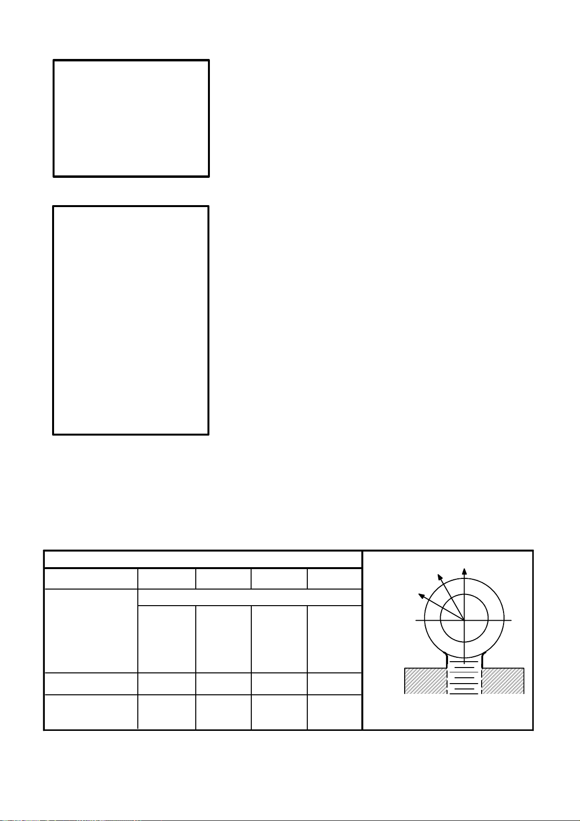
EYEBOLTS
A straight lift is preferred when using eyebolts. An angular lift places
additional stresses on an eyebolt, above that of the load to be hoisted.
Ifthe situationnecessitatesan angularlift, thesafe workingload forangular
lifts shown in Fig. 1 and Fig. 2 should be used.
Whenmultiple eyeboltprovisions aredesignedinto alift, itisrecommended
(in most applications) that a spreader bar be used. (See Fig. 9 which
illustrates a typical spreader bar arrangement.)
No greater stress should be allowed than that given under Safe Working
Load in Fig. 1 and Fig. 2.
To obtain greatest strength from an eyebolt, it must fit reasonably tight in
the hole with at least 90% of the threaded length engaged.
Eyebolts should never be welded or subjected to heat in excess of 900F
[480 C].
Eyebolts should never bepainted orotherwise coatedwhen usedfor lifting,
as such coating will very likely cover up flaws.
Eyebolts should be routinely inspected for defects and if any defects are
found,theyshould bedestroyedby melting,crushing, orcuttingclearacross
the eye.
STRAIGHT SHANK INCH (ANSI/ASMEB18.15)
THREAD .375--16 .500--13 .625--11 1.000--8
SAFE WORKING LBS. [KG]
LOAD
90 DEGREES 1000 1840 2940 7880
[453] [834] [1333] [3573]
60 DEGREES 375 805 1340 3670
[170] [365] [607] [1664]
30 DEGREES 200 470 805 2390
[90] [213] [365] [1083]
PART NUMBER 3449 870 21312 19489
IDENTIFICATION
PLATE NUMBER 3338325 3338326 3338327 3338328
60
30
STRAIGHT SHANK INCH
90
Fig. 1
Preferred Inch Lifting Eyebolts
Page 1--6
Cincinnati Machine 91203809--001
Page 23
SHOULDER METRIC (ISO 3266--1984)
THREAD M12 M16 M20 M30
SPOTDIAMETER 32mm 37mm 42mm 67 mm
1.25 in. 1.50 in. 1.65 in. 2.63 in.
SAFE WORKING [KILOGRAMS] LBS.
LOAD
90 DEGREES [400] [630] [1000] [2500]
882 1389 2205 5512
45 DEGREES [100] [160] [250] [625]
220 352 551 1378
PART NUMBER 6014453--3 6014453--4 6014453--5 6014453--8
45
90
IDENTIFICATION
PLATE NUMBER 3338329 3338330 3338331 3338332
Fig. 2
Preferred Metric Lifting Eyebolts
5 MAX.
LOAD
NO
LOAD
30 MIN.
YES
YES
NO
Fig. 3
Eyebolt Loading
6.00
THIS MACHINE HAS BEEN
MANUFACTURED TO UTILIZE
”INCH” THREAD LIFTING
3.00
DEVICES. ANY EXCEPTION
TO THIS WILL BE LABELED
ADJACENT TO THE LIFT
POINT.
.12
.12
TYP.
NO 21 (.032) GAGE ALUMINUM.-- NO.AL 5052 ALLOY.ETCHED AREA S TO
BEBLACK BAKED ENAMEL. ETCHEDDEPTHTO BE .003 TO .005INCHES
------ OR ------ NO. 21 (.032)GAGE
ALUMINUM WITH METALPHOTOPROCESS.ALL LETTERINGTO BE HELVETICA MEDIUM.
.109 DIA.THRU
4PLACES
3375984
.08
.25
.12 R
Fig. 4
Eyebolt I.D. Plates -- Inch and Metric
3TYP.
NO 21 (.032) GAGE ALUMINUM.-- NO. AL 5052 ALLOY. ETCHED AREAS TO BE BLACK
BAKED ENAMEL. ETCHED DEPTH TO BE .003 to .005 INCHES ------ OR ------ NO. 21 (.032)
GAGE ALUMINUM
WITH METALPHOTO PROCESS. ALL LETTERING TO BE HELVETICAMEDIUM.
SURFACE GRAIN TO RUN PARALLEL TO LETTERING WITH SATINFINISH.
INCH
.375--16 UNC
THIS MACHINE HAS BEEN
MANUFACTURED TO UTILIZE
”METRIC” THREAD LIFTING
DEVICES. ANY EXCEPTION
75
TO THIS WILL BE LABELED
ADJACENT TO THE LIFT
POINT.
1.4
THRU--4
3TYP.
PLACES
3338325
SHOULDER METRIC
ISO METRIC
150
6.3
3375983
2
3R
3338329
M12
Fig. 5
Instruction Plate -- Inch (Part Number 3375984)
Cincinnati Machine 91203809--001 Page 1--7
Fig. 6
Instruction Plate -- Metric (Part Number 3375983)
Page 24
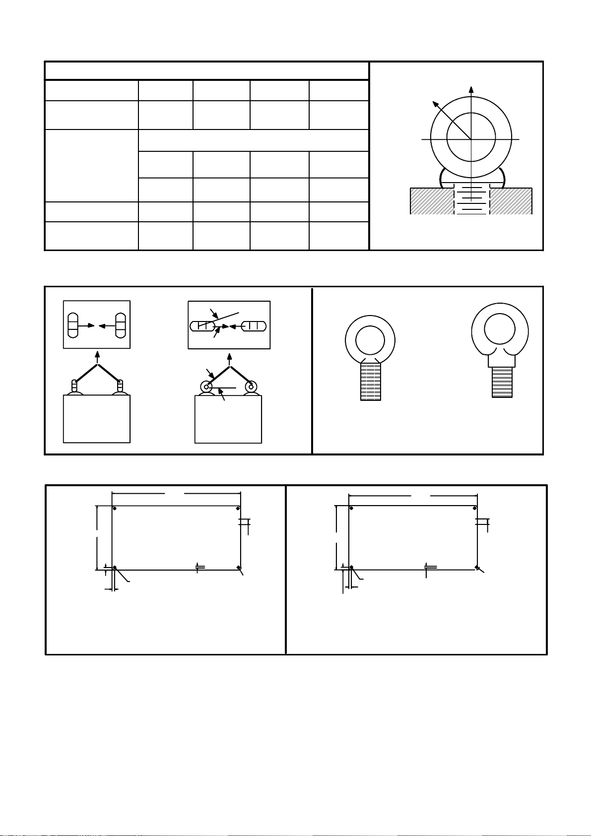
HOIST RINGS
A
PAR
T.N
O
PLATE
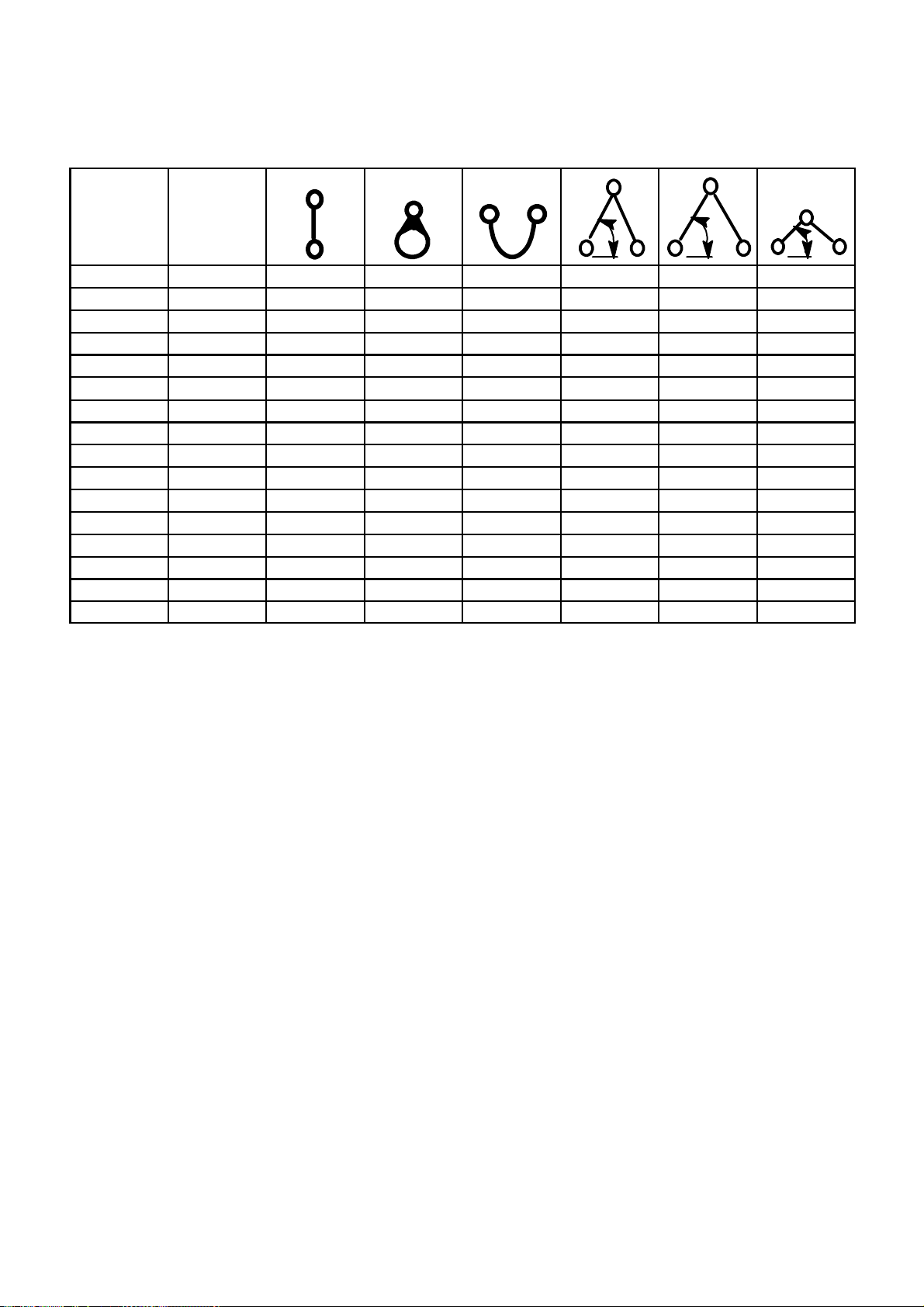
Hoist Rings are superior to eyebolts for angular lifting.
Be certain the thread projection is in accordance with the manufacturer’s
recommendation.
Do not recut any damaged threads on hoist rings.
To obtain the safe working load, torque to the recommended values shown
in the table below.
Fig. 7
Hoist Ring
CM HOIST
RING
PARTNO.
3346225 1 .375--16 12.0 16.3 1000 450 866 390 707 318 500 225 5013055 001
3346225 2 .500--13 28.0 38 2500 1130 2165 975 1767 795 1250 562 5013055 002
3346225 3 .625--11 60.0 81.3 4000 1810 3464 1559 2828 1273 2000 900 5013055 003
3346225 4 1.000--8 230.0 312 10000 4500 8660 3897 7071 3182 5000 2250 5013055 004
3346225 6 M12X1.75 27.0 36.6 2204 991 1908 859 1558 701 1102 496 5013055 006
3346225 7 M16X2 59.0 80 3857 1736 3340 1503 2726 1227 1928 868 5013055 007
3346225 8 M20X2.5 100.0 136 4736 2132 4103 1846 3349 1507 2369 1066 5013055 008
3346225 9 M30X3.5 229.0 310 9257 4166 8016 3607 6544 2945 4628 2083 5013055 009
CM HOIST
RING
PARTNO.
3346225 1 .375--16 12.0 16.3 1000 450 1000 450 1000 450 5013055 001
3346225 2 .500--13 28.0 38 2500 1130 2500 1130 2500 1130 5013055 002
3346225 3 .625--11 60.0 81.3 4000 1810 4000 1810 4000 1810 5013055 003
3346225 4 1.000--8 230.0 312 10000 4500 10000 4500 10000 4500 5013055 004
3346225 6 M12X1.75 27.0 36 2204 991 2204 991 2204 991 5013055 006
3346225 7 M16X2 59.0 80 3857 1736 3857 1736 3857 1736 5013055 007
3346225 8 M20X2.5 100.0 136 4736 2132 4736 2132 4736 2132 5013055 008
3346225 9 M30X3.5 229.0 310 9257 4166 9257 4166 9257 4166 5013055 009
Fig. 8
Hoist Ring Table
THREAD
SIZE
THREAD
SIZE
THREAD
TORQUE
Ft--Lb N--m Lb kg Lb kg Lb kg Lb kg
THREAD
TORQUE
Ft--Lb N--m Lb kg Lb kg Lb kg Ft--Lb N--m
Observe all other safety precautions normally practiced on eyebolts.
FF
90
_
WW
MAX. WT
EACH RING
FF
90
_
WW
MAX. WT
EACH RING
FF
60
_
WW
MAX. WT
EACH RING
FF
90
WW
MAX. WT
EACH RING
FF
45
_
WW
MAX. WT
EACH RING
FF
90
WW
MAX. WT
EACH RING
FF
30
_
WW
MAX. WT
EACH RING
NOTE F=FORCE W=WEIGHT
CM IDENT.
P
CM IDENT.
PART. NO.
.xxx--xx
PLATE
RT. NO.
.xxx--xx
.
Page 1--8
Cincinnati Machine 91203809--001
Page 25

SPREADER BARS AND LIFTING BEAMS
p
y
p
SPREADER
TO LOAD TO LOAD
Fig. 9
S
reader Bar -- T
ical
Spreader bars are used when multiple eyebolts are designed into a lift.
Always observe the following safety precautions when using a spreader bar
or lifting beam
Do not exceed the safe working load.
Use the spreader or beam to handle parts or components only for which it
was designed.
Inspect it before each use.
Do not alter or weld anything to bar or beam.
Store properly to avoid damage.
CHAIN
Selectachain withthe suitablecharacteristics andcapacityforthe load.See
above. Always observe the following safety precautions.
Do not shorten chains with knots, bolts, or any non--approved method.
Never use damaged chain.
Hitch chain securely to the load.
Pad sharpcorners with material of sufficient strengthto withstand loadand
protect chain.
Cincinnati Machine 91203809--001 Page 1--9
Page 26
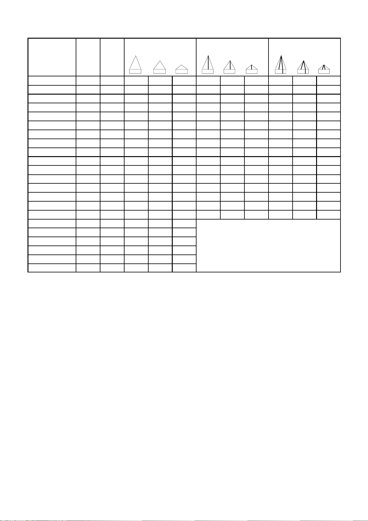
DOUBLE SLING CHAINS
SIZE OF
CHAIN
9/32 in. lbs. 3 250 5 625 4 600 3 250 8 400 6 900 4 875 8400 6900 4 875
.7.2 mm kg. 1 475 2 550 2 085 1 475 3 810 3 130 2 210 3 810 3 130 2 210
3/8 in. lbs. 6 600 11 400 9 300 6 600 17 100 13 950 9 900 17 100 13 950 9 900
9.5 mm kg. 2 995 5 170 4 220 2 995 7 750 6 330 4 490 7750 6 330 4 490
1/2 in. lbs . 11 250 19 700 15 900 11 250 29 250 23 850 16 875 29 250 23 850 16 875
712.7 mm kg. 5 100 8 845 7 210 5 100 13 270 10 820 7650 13 270 10 820 7650
5/8 in. lbs . 16 500 28 600 23 300 16 500 42 900 34 950 24 750 42 900 34 950 24 750
15.9 mm kg. 7 480 12 970 10 570 7 480 19 460 15 850 11 230 19 460 15 850 11 230
3/4 in. lbs . 23 000 39 800 32 500 23 000 59 700 48 750 34 500 59 700 48 700 34 500
19.1 mm kg. 10 430 18 050 14 740 10 430 27 080 22 110 15 650 27 080 22 110 15 650
7/8 in. lbs . 28 750 49 800 40 700 28 750 74 700 61 050 43 125 74 700 61 050 43 125
22.6 mm kg. 13 040 22 590 18 460 13 040 33 880 27 690 19 560 33 880 27 690 19 560
1in. lbs . 38 750 67 100 54 800 38 750 100 650 82 200 58 125 100 660 82 200 58 125
25.4 mm kg. 17 580 30 440 24 860 17 580 45 650 37 290 26 260 45 650 37 290 26 260
1 1/4 in. lbs. 57 500 99 600 81 300 57 500 149 400 121 950 86 250 149 400 121 950 86 250
31.8 mm kg. 26 080 45 180 36 880 26 080 67 770 55 320 39 120 67 770 55 320 39 120
1 1/2 in. lbs. 80 000 138 500 113 000 80 000
38.1 mm kg. 36 290 62 820 51 260 36 290
1 3/4 in. lbs. 100 000 73 200 41 000 100 000
44.5 mm kg. 45 360 78 560 63 960 45 360
2in. lbs . 130 000 225 000 183 000 130 000
50.8 mm kg. 26 750 102 060 83 000 26 750
SINGLE
CHAIN
90
TYPE D
60 45 30
TRIPLE SLING CHAINS
TYPE T
60 45 30
QUAD SLING CHAINS
TYPE Q
60 45 30
Fig. 10
Steel Alloy Chains
Keep hands and fingers from between the chain and load.
Avoidshock l oading --particularlywhenworkingattemperaturesbelow40
F[4 C].
Never pull chain from under load when load is resting on chain.
Correct kinks and twisting in chain before lifting.
Lift from center of hooks. Avoid lifting from the point.
Assurethat loadis freeto movebeforelifting. Keepclearof allobstructions.
When using a basket hitch, balance load and assure that chain legs contain
or support load from the sides above the center of gravity.
Storechains inan areawherethey will not be subjectto mechanical damage
or corrosive action.
Page 1--10
Cincinnati Machine 91203809--001
Page 27
CABLE SLINGS
Select the appropriate size wire rope and hitch. See Table below
CABLE
SIZE
1/4 in. lbs. 980 740 1400 1700 1400 980
6.4 mm kg. 445 335 635 770 635 445
1/2 in. lbs. 3600 2800 5200 6400 5200 3600
712.7 mm kg. 1630 1270 2360 2900 2360 1630
3/4 in. lbs. 7800 5800 11100 13600 11100 7800
19.1 mm kg. 3450 2630 5035 6170 5035 3450
1in. lbs. 13400 1000 18800 22000 18800 13400
25.4 mm kg. 6080 4540 8530 9980 8530 6080
1 1/4 in. lbs. 19600 14800 28000 34000 28000 19600
31.8 mm kg. 8890 6710 12700 15420 12700 6710
1 1/2 in. lbs. 28000 20000 40000 48000 40000 28000
38.1 mm kg. 12700 9070 18140 21770 18140 12700
1 3/4 in. lbs. 38000 28000 54000 66000 54000 38000
44.5 mm kg. 17240 12700 24490 29940 24490 17240
2in. lbs. 50000 36000 70000 86000 70000 50000
50.8 mm kg. 22680 16330 31750 39000 31750 22680
Fig. 11
Wire Rope Slings
ESTIMATED
RATINGCA-
PACITY
(For Exact
Rating Check
Sling Tag)
VERTICAL
CHOKER
HITCH
BASKET
HITCH
60 45
30
Guide loads with a tag line when practical.
When using multiple leg sling, select longest one possible.
Examine for damaged or worn area.
Attach securely to load.
Pad sharp corners to protect wire rope.
Center load in the base (bowl) of the hook to prevent hook point loading.
Do not kink, twist, or loop legs.
Keep hands and fingers from between wire rope and load.
Stand clear of attached load.
Start lift slowly to avoid shock injury.
Do not pull wire rope from under a load when the load is resting on it.
Do notshorten sling byknotting, by wirerope clips, orby any othermeans.
Do notinspect wire rope by passingbare hands overthe body. Brokenwire,
if present, may puncture the hands.
Keep wire rope well--lubricated to prevent corrosion.
Use gloves at all times when handling.
Cincinnati Machine 91203809--001 Page 1--11
Page 28
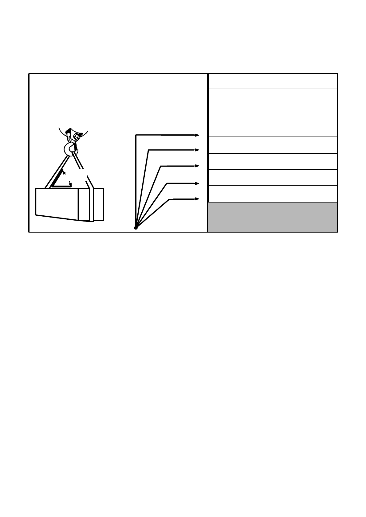
SYNTHETIC MATERIAL SLINGS
Select the sling with the suitable characteristics and capability for the load
and environment. See Fig. 12
AS THE SLING TO LOAD ANGLE
DECREASES, SO DOES THE RATED CAPACITY OF A SLING.
SLING--TO--LOAD ANGLE IS ALWAYS
THE ANGLE BETWEEN THE SLING LEG AND
THE HORIZONTAL SURFACE.
SLING
TO
LOAD
ANGLE
Fig. 12
Sling Load Angle Chart
USE THISCHART
FOR ALL TYPE
SLINGS; ROPE,
CHAIN, OR NYLON.
90
75
60
45
30
RATEDSLING CAPACITY--ONE LEG
SLING
LIFTING
EFFICIENCY
100.0 %
96.6 %
86.6 %
70.7 %
50.0 %
If Sling Ca-
pacity
at 90
is...
(LB. [KG])
1000
[454
]
1000
[454
]
1000
[454
]
1000
[454
]
1000
[454
]
Then Actual
Sling Capacity
is ...
(LB. [KG])
1000
[454
]
968
[439
]
866
[390
]
707
[320
]
500
[225
]
When usinga choker hitch,the sling shall be long enough to assurethat the
choking action is on the webbing.
Slings used in a basket hitch shall have the l oad balanced.
Do not drag slings over the floor or any abrasive surface.
Do not twist or tie knots in slings.
Never pull sling from load when the load is resting on it.
Protect sling from sharp corners and abrasive surfaces.
Do not drop slings.
Store slings in an area where they will not be subject to mechanical or
chemical damage.
Do not use where acid conditions exist.
Do not use polyester and polypropylene slings where caustic conditions
exist.
Do not use polyester and nylon slings at temperatures in excess of 180
F nor polypropylene slings at temperatures in excess of 200 F.
Do not use aluminum fittings where caustic conditions exist.
Page 1--12
Cincinnati Machine 91203809--001
Page 29
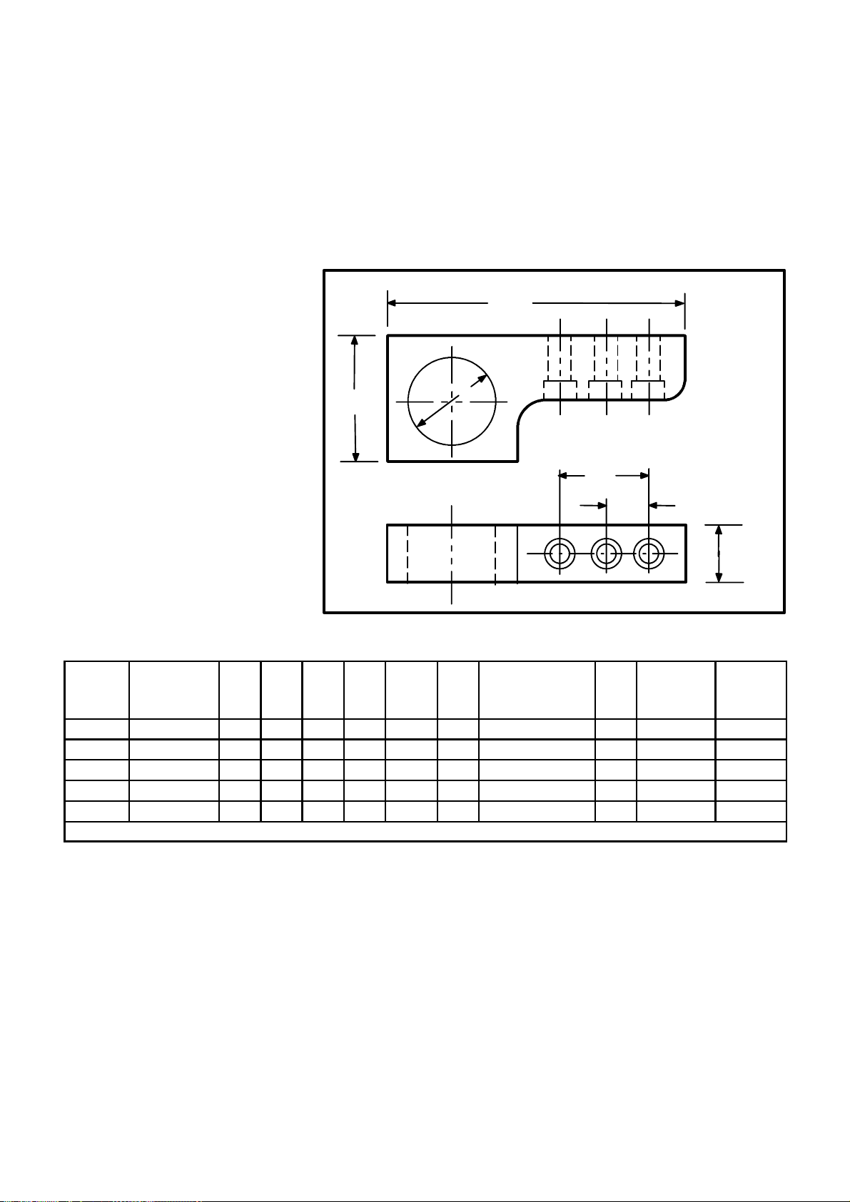
P TYPE HOOKS
N
O
P type hooks are a proprietary design and should be considered for heavy
(machine and unit) lifts.
Fig. 14 givesdimensional data,safe workingloads andscrew torquevalues
for P type hooks.
The use of these hooks must be shown on the assembly drawing, listed in
the Bill of Material and shownin the lifting sectionof the ServiceManual.
B
D
C
F
E
Fig. 13
“P” Type Lifting Hooks
PART
NO.
.
402517 1800 [818] 2.00 9.75 4.50 3.00 2.50 -- -- -- 2415 2 160 217
296513 2500 [1136] 1.75 10.63 4.00 2.50 4.00 -- -- -- 2415 2 160 217
296514 3500 [1590] 2.00 12.25 4.50 3.00 2.50 5.00 2415 3 160 217
402335 5000 [2273] 2.25 12.25 4.50 3.00 5.00 -- -- -- 180139 2 370 502
296515 8000 [3636] 2.25 15.75 4.50 3.00 4.00 7.88 180139 3 370 502
Fig. 14
“P” Type Lifting Hooks
LIFTING SCREW SCREW
CAPACITY
LBS. [KG]
A B C D E F SCREW NO. QTY.
INCH INCH INCH INCH INCH INCH
WHEN DESIGNING METRIC SIZES SEE THE CURRENT LIFTINGMANUAL
TORQUE TORQUE
LB./FT. N--m
S HOOKS
A
The use of S hooks in conjunction with some of the other lifting devices
dictates additional safety rules which must always be practiced.
Never use more than one S hook in a single chain link or hook.
Inspect the S hook before each use and if damaged destroy by cutting into
two pieces.
Neverexceed thesafe working loadwhich should bestamped oneach hook.
Do not paint, weld, or expose an S hook to high heat.
Cincinnati Machine 91203809--001 Page 1--13
Page 30
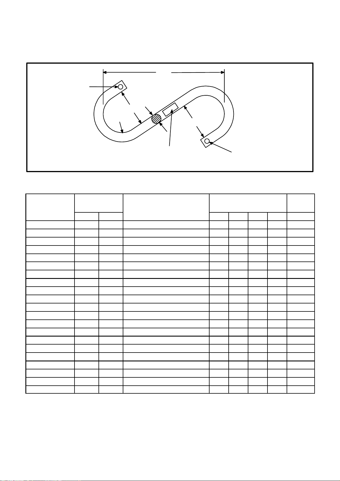
STAMPTO
INDICATE ALLOY
Do not use when either or both S hooks are opened more than 15% of the
normal throat opening or twisted more than 10 from the plane of the
unbent hook.
B
A
C
R(REF.)
STAMPWORKING LOAD LIMIT WITH LOW STRESS
CHARACTERS PER NUCLEAR AMERICAN
SOCIETY OF MECHANICAL ENGINEERS CODE
SECTION III, DIV. 1, PARAGRAPH NA--3766.6 (2)
C
STAMP MFGR. NAME OR TRADEMARK FOR
IDENTIFICATION
Fig. 15
“S” Hooks
PARTNO.
MAX. WORKING
LOAD
LBS. KG
MANUFACTURER AND
CODE NUMBER
ALL DIMENSIONS IN
INCHES
(See Fig 16.)
S--HOOK
WEIGHT
A B C R LBS.
3590535--5 650 294 CM Chain 562250 0.500 7.50 2.00 1.00 0.80
Amer. Chain & Cable 5933--00800 0.500 5.50 1.50 0.75 0.63
3590535--7 1 015 460 CM Chain 562262 0.625 9.00 2.50 1.25 1.60
Amer. Chain & Cable 5933--01000 0.625 7.00 1.88 0.94 1.30
3590535--8 1 465 664 CM Chain 562275 0.750 10.50 3.00 1.50 2.60
Amer. Chain & Cable 5933--01200 0.750 8.25 2.25 1.12 2.10
3590535--9 1 990 902 CM Chain 562287 0.875 12.00 3.50 1.75 4.20
Amer. Chain & Cable 5933--01400 0.875 9.62 2.62 1.31 3.40
3590535--10 2 600 1179 CM Chain 562300 1.000 13.00 4.00 2.00 6.00
Amer. Chain & Cable 5933--01600 1.000 11.00 3.00 1.50 5.10
3590535--12 3 290 1492 CM Chain 562310--B 1.125 15.00 4.50 2.25 8.70
Amer. Chain & Cable 5933--01800 1.125 12.12 3.38 1.69 7.00
3590535--14 4 065 1843 CM Chain 562325--B 1.250 16.00 5.00 2.50 11.70
Amer. Chain & Cable 5933--02000 1.250 13.75 3.75 1.88 10.00
3590535--15 4 915 2229 CM Chain 562337--B 1.375 17.00 5.50 2.75 15.40
Amer. Chain & Cable 5933--02200 1.375 14.88 4.12 2.06 13.00
3590535--16 5 850 2653 CM Chain 562350--B 1.500 18.00 6.00 3.00 19.50
Amer. Chain & Cable 5933--02400 1.500 16.50 4.50 2.25 17.50
3590535--18 9 500 4309 Amer. Chain & Cable 5933--02800 1.750 19.25 5.25 2.62 28.00
3590535--20 12 500 5669 Amer.Chain & Cable 5933--03200 2.000 22.00 6.00 6.00 41.00
3590535--25 19 000 8618 Amer.Chain & Cable 5933--04000 2.500 27.50 7.50 9.75 79.00
Fig. 16
“S” Hooks
Page 1--14
Cincinnati Machine 91203809--001
Page 31

U TYPE HOOKS
U type hooks are a proprietary design and should be considered for heavy
(machine and unit) lifts.
Fig. 17 and Fig. 18 give dimensional data, safe working loads and screw
torque values for U type hooks.
The use of these hooks must be shown on the assembly drawing, listed in
the Bill of Material and shownin the lifting sectionof the ServiceManual.
C
B
D
A
Fig. 17
“U” Type Lifting Hooks
LIFTING SCREW SCREW
PARTNO.
303427 1 500 [680} 2.75 4.00 2.25 1.25 3248 2 45 61
303429 3 500 [1587] 3.25 4.50 2.50 1.50 2400 2 90 122
301269 6 000 [2720] 4.00 6.00 3.75 2.00 2415 2 160 217
301270 8 000 [3600} 5.00 6.50 3.88 2.25 180139 2 570 502
301271 12 000 [5442] 6.00 8.00 4.50 2.50 308196--- 3 2 735 997
301272 16 000 [7256] 7.00 9.50 5.30 3.00 308197--- 4 2 1290 1749
311105 25 000 [11 337] 7.00 14.25 6.00 3.50 308197---4 2 1290 1749
990819 1 500 [680] 75 107 60 32.0 1234074 2 41 30
3988405 3 000 [1360] 90 120 65 38.0 1234100 2 108 80
3990821 6 000 [2720] 105 155 95 50.0 1400264 2 230 170
5024235 8 000 [3600] 130 180 103 57.2 1400400 2 407 300
5025776 14 000 [6500] 170 250 133 76.2 6010088--3 2 1356 1000
5026032 22 500 [10 200] 300/180 380 159 88.9 6010088--3 4 1356 1000
CAPACITY
LB. [KG] in in in in SCREW NO. QTY. LB./FT. N--m
LB. [KG] mm mm mm mm SCREW NO. QTY. N--m LB./FT.
A B C D
TORQUE TORQUE
Fig. 18
“U” Lifting Hook Table
Cincinnati Machine 91203809--001 Page 1--15
Page 32

GENERAL SAFETY LIFTING INFORMATION
Allhooks or cranes orany othertype liftingdeviceshould beequipped with
a safety latch (see Fig. 19) similar to t he one manufactured by the
Harrington Co., Plymouth Meeting, Pennsylvania.
Fig. 19
Safety Latch
Illustrations or descriptions of any special lifting devices or techniques
required for servicing components of a specific machine are found in the
section dealing with the particular component.
Always contact the nearest Cincinnati Machine representative if there are
any questions regarding the lifting of any machine components.
Page 1--16
Cincinnati Machine 91203809--001
Page 33

WARNING
CUTTING FLUIDS
When soluble coolants
areused,it is important to
ensure that recommended concentration
levels are maintained.
Fluids Used With Machine Tools
General Considerations
Variousfluid products, suchas cutting fluids,lubricants, etc., areused with
this machinetool. The correct type andquantity is identified byinstruction
plateson themachineand/or writteninstructions inthesupplied manual(s).
Before using fluids or related products not specifically approved or
recommended with this machine tool, the owner/user should contact the
authorized supplier, closest Cincinnati Machine regional field office for
assistance in determining if the product is suitable for the particular
application.
Lubricants
Only those lubricants (oils and greases) tested and approved by Cincinnati
Machine, should be used in Cincinnati machine tools. For information
concerning latest lubricants manual, contact Cincinnati Machine service
department.
Cutting Fluids
Before filling the machine, ensure that the product is suitable for the
application. Frequently, check for storage, tank unit or hose leaks.
Watermixedfluidsthatcontainemulsifiersmustbeprotectedfromfreezing.
Cutting fluid products should be tailored to eachmachine tool application
and workpiece requirement for maximum efficiency. See WARNING.
Failure to follow this Instruction can cause corrosion of safety critical
parts, resulting in machine damage and/or personal injury.
For assistance in determining the correct cutting fluid, contact nearest
Cincinnati Machine Service Department.
Sources Of Information -- USA
Beforeusinganyfluidproductwiththismachinetool,theowner/usershould
request a Technical Data Product Safety Sheet (for example: OSHA Form
20 or a similar technical data information sheet) from the product
manufacturer. This data should include the following:
Fire and Explosion Hazard Chemical and Trade Name
Data Acute Toxicity Properties
Spill or Leak Procedures Hazardous Ingredients
Special Protective Information Physical Data
Special Precautions Recommended Dilutions
Cincinnati Machine 91203809--001 Page 1--17
Page 34

Listed below are some other sources which can be contacted to obtain
additional up--to--date information concerning the safe use, handling,
storage and disposal of products, materials, chemicals or substances.
Occupational Safety and Health Resource Conservation and
Act (OSHA) Public Law Recovery Act (RCRA) Public Law
Department of Transportation National Institute for
(DOT) Hazard Classification— Occupational Safety and
The Transportation Safety Act Health (NIOSH)
Product Safety Data Sheet Cincinnati Machine
Toxic Substances Control Act P.O. Box 9013
(TSCA) Public Law Cincinnati, Ohio 45209
Federal Insecticide, Fungicide and American National Standards
Rodenticide Act (FIFRA) Public Institute, Inc. (ANSI)
Law
American Conference of
Environmental Protection Agency Governmental Industrial
Hygienists,
Threshold Limit
Federal Hazardous Substances Act Values
Clean Water Act
After receiving the data, analyze andperform the necessaryprocedures to
assure the safe handling, storage, use and disposal of the product.
Emergency/FirstAid proceduresand trainingshould bereadily availableto
personnelhandlingorusing products whichmaybehazardous (flammable),
harmful (toxic) and/or reactive (unstable)
The owner/user should become familiar with and keep informed on all
regulated materials or substances. Copies of the latest regulated material
may be obtained from agencies, such as NIOSH, Registry of Toxic Effects
for Chemical Substances, U.S. Department of Health Education and
Welfare, Public Health Service, Center for Disease Control, and the
National Institute for Occupational Safety and Health.
Usage Information
Products must not be mixed with other products unless permission and/or
instructionshavebeengrantedby themanufacturer(s). Productconcentrates
must be mixed and diluted exactly as instructed by the manufacturer for a
particular approved application.
All productCAUTION, WARNINGand DANGER labels,tags and printed
instructions accompanying the products must be read and followed This
instruction shall remain with the product at all times. Additional product
instruction labels, signs, etc., should be acquired and displayed with
concentrates that are purchased in bulk and then dispensed in small or
diluted quantities
Page 1--18
Cincinnati Machine 91203809 --001
Page 35

Cutting Fluids -- Preventative Maintenance
SeeCautions1and2
CAUTION 1
COOLANTS
It is not recommended that
neat mineral oils be used as
a cutting fluid for this machine.
Failure to heed this warning
could seriously impair the efficiency of both the coolant
and swarf removal systems.
CAUTION 2
COOLANTS
It is not recommended that
coolants having a high demulsification factor, be used
with this machine.
Such coolants must be
checked for compatability
withtheoils andgreasesrecommended for use with this
machine.
Failure to follow this instruction can lead to lubrication
problems, resulting in damage to the machine.
Cutting fluids are designed to cool and lubricate the tool tip while in a cut.
There are many types of cutting fluids, some of which may cause various
problems on a machiningcenter tool, such as corrosion, bacteria build--up,
solid formations of chips and cutting debris, etc. if incorrectly applied.
The user should be aware of these potential problems, and guard against
them.
Two types of cutting fluids can be used on this machine, semi--synthetics,
andemulsions. Each hasitsown advantagesand disadvantagesand theuser
should consider all of them when making a product selection.
Water Quality
Water i s the majoringredient ina water--basedcutting fluid. Its importance
in product performance cannot be ignored.
Corrosion, residue, scum, rancidity, foam, excess concentrate use, in fact
almostany cuttingfluid performanceproblem maybecaused bythe quality
of the water used in making the mix.
Too Soft
Whenthe mixwaterhas atotalhardness oflessthat 75ppm,thecutting fluid
may foam --especiallyinapplicationswherethereisagitation. Foamcauses
problems when it overflows the reservoir, the machining center, the return
trenches,etc. Foammayalsointerfere withsettlingtype separators,obscure
the workpiece, and diminish the cooling capacity of a water--based cutting
fluid. Generally, all products foam more readily in soft water.
Too Hard
Hard water, when combined with some water--based cutting fluids,
promotes the formation of insoluble soaps. The dissolved minerals in the
water combine with anionic emulsifiers in the cutting fluid concentrate to
form these insoluble compounds that appear as a scum in the mix. Such
scum coats the sides of the reservoir, clogs the pipes and filters, covers
machining centers with a sticky residue, and may cause sticking gauges,
pushbuttons, selector switches, and other similar devices.
Hard water can promote corrosion of machine components and should
always beeliminated. De--ionized waterwill helpdeal with theproblem of
hard water, provided advice has been sought.
Cleaning The Coolant Reservoir
The systemrequires periodic attention andservicing. The reservoir should
be drained and cleaned periodically to remove sediments and prevent
conditions that lead to deterioration of the coolant. The reservoir can be
cleaned by removing the used fluid before adding and circulating a
commercial cleaner or as required by adding a suitable cleaner to the used
coolant in the machining center during a shut--down period while the
machineis cycling. Specificcleaning proceduresshould besupplied onthe
label of each cleaning product.
Cincinnati Machine 91203809--001 Page 1--19
Page 36

Lifespan
The lifespan of cutting fluids varies widely and depends on many factors.
Thebasic typeofcoolant, thehardness ofthewater,the typesof metalin the
coolant tank, the cleanliness of the system, and the amount of tramp oil in
the fluid, all are factors that affect lifespan.
Tramp Oil
Tramp oils need to be controlled. Tramp oils in the coolant mix cause a
varying degree of degradation of the coolant quality.
Minimizethe leakageofoils intothe systemthroughproper maintenanceof
sealsand lubricantsystems. If excessquantities ofoilsleak intothesystem,
the metalworking fluid performance can be reduced. Lubricating and
hydraulic oils contain food for bacteria. They may also blanket the fluid,
excluding air, and thereby provide ideal conditions for the growth of odor
producing bacteria. If allowed to build up, extraneous oil causes smoking
and increases residue around the machining center area.
The elimination of tramp oils is even more important if chemical cutting
fluids are used. Hydraulic oil is a contaminant that must be kept out of the
cutting fluid. Hydraulic oils, and particularly some of the additives
formulatedintothem,cancauseseriousdamagetothemachinetooland
cutting fluid when mixed with water.
Iftrampoilbuild--upshouldbecomeaproblem,various commercial devices
are available to remove it.
Filtering
The cleanliness of the coolant is very important in regards to the reliability
of the various coolant valves, tubing, etc. This Machining Center is
equipped witha coolant filter system. It is good practice t o ensure that any
filters are kept in good operating condition.
Rust Prevention
When a machining center tool is sitting idle for a period, the possibility of
corrosionincreases. There arecertain precautionsthat the usermust taketo
prevent damage to the precision ground surfaces on this machine tool.
Under certainconditions, damage canoccur within aslittle time asa day or
two; therefore, it is important that proper precautions be carried out.
Ifthemachining centerisgoing tosit idlefora period,itisimportant towipe
all the coolant off the slideways and then protect them with a good
rust--preventive. On the horizontal axes of themachining center,it may be
necessarytoruntheslidesbackandforthanumberoftimes, wiping theways
each time, until no coolant is seen originating from under the slide.
Page 1--20
After thecoolant is clear fromunder the slide, spraythe rust--preventive on
thewaysandmovetheslideagain, takingthe rust--preventiveback underthe
slide.
Cincinnati Machine 91203809 --001
Page 37

WARNING 1
Donot exposePCBoardsto
electro--static discharge,
as intermittent board failures may occur and cause
erratic machine operation.
Failure to follow this
instruction may result in
personal injury.
WARNING 2
Qualified electrical personnel must disconnect all
electrical power before
printed circuit boards are
replaced. Failure to follow
this instruction may result
in personal injury.
WARNING 3
Do not set PC Boards in
styrofoam, waxed, rubber,
plastic or other high rated
non--conductive(dielectric)
materials. Failure to follow
this instruction may result
in personal injury.
Printed Circuit Board Handling Instructions
General
All integrated circuits are susceptible to electro--static discharge damage.
Because of this condition, special procedures must be used when handling
circuit boards containing integrated circuits, even though there is no
completelyfoolproof system of protectingintegrated circuits. Metal oxide
semi--conductor (MOS) assemblies manufactured byVickers Electronic
Systems Division Incorporated are supplied with a caution sticker. Refer
to the sticker and the information concerning cautions and warnings in the
supplied literature.
NOTE: It is important to emphasize that electro--static discharge to a PC
Board may not completely destroy an assembly component, but
severely de--grade this component to a point where intermittent
failures may occur.
If static discharge occurs at sufficient magnitude (2kV or greater) damage
or degradation will usually occurif recommended handling procedures are
notused. Personnelhandling equipmentin alowhumidity environmentcan
generate static potentials in excess of 10kV. Do not touch any integrated
circuit assembliesat the pins, leads or edgeconnectors, since most damage
is done at these points. See WARNING 1.
Recommended Handling Procedure
Before removing or replacing any PC B oard, a qualified technician must
disconnect all electrical power, including battery back--up devices. Refer
to the machine dedicated electrical diagrams. See WARNING 2.
A recommended procedure before handling printed circuit boards is as
follows:
1. Attach a grounded ”wrist strap” in contact with the skin. This strap
should have a resistor value of 1 megohm (1/2 watt) in series with
the person and grounded to leak off electro--static discharge.
2. When working with static control devices (for example: a bag or
pad), touch the device with your grounded hand. This action will
place you and the static control device assembly at the same
electro--static potential.
Store and transport the printed circuit boards in static control bags. Use
”shortingbars” orconductive foammaterials. Do not usea suspectedstatic
damaged printed circuit board. See W ARNING 3.
Below are examples of electro--static caution symbols which may appear in
areas of concern (for example: packing, shipping or receiving). These
symbols s ignify that the ”Recommended Handling Procedures” must be
used and/or follow any special supplied instruction.
Cincinnati Machine 91203809--001 Page 1--21
Page 38

WARNING 1
Safety Features
PERIMETER GUARDING
It is imperative that this
guarding is kept intact
and in place at all times
during normal operation
of the machine.
In such cases where a
part of the guarding has
toberemoved for maintenance purposes, the
guardingMUSTbere-fitted before the machine
is allowed to go back into
normal operation.
Failure to follow this
instruction may result in
serious personal injury.
WARNING 2
OPERATOR DOORS
POWER LOSS
If machine power is lost
whilst the doors are in
theirclosedposition,they
will remain latched in that
position until powerisre-applied.
The doors can be opened
from the inside using the
special key attached to
the top of the SHOT BOLT
body. Do not attempt to
operate the machine with
the doors open.
Failure to follow this
instruction may result in
serious personal injury.
Perimeter Guarding
A complete set of perimeter guards is supplied and fitted to this machine.
See WARNING 1.
OPERATOR ACCESS TO THE MACHINE is gained at the following
point:--
Operator Doors -- for loading andunloading componentsand for settingup
purposes.
Operator Sliding Door(s)
See WARNING 2.
With the door(s) closed and machine power on, a safety switch is actuated
that allows automatic machine movements to be executed.
It is not possible to open the operator door/s while the machine is in
automatic cycle, due to the latching mechanism of the switch.
With the door(s) open and machine power on, the following conditions
apply:
1. Spindle rotation is inhibited.
2. Power feed of the X, Y, Z axes are limited to 2m/min maximum.
The following functions are also available for selection.
1. Coolant Start
2. Manual clamp/unclamp of the spindle drawbar.
Page 1--22
Cincinnati Machine 91203809--001
Page 39

CAUTION
Emergency Stop
Feed Hold Push Button
Provides logical and safe interruption of the active machine cycle when
actuated.
Emergency Stop Push Button
Actuatingthisbutton withthe
machine in a cutting cycle
may damage cutting tools
and work pieces.
Failure to follow this instruction may resultin damage to
equipment.
DANGER
Electrical Iso latio n
Switch
This switch does not isolate the incoming supply
to the cabinet or the supply to the Transformer
Unit.
It should also be noted
that it may take up to 20
minutes to discharge
completely the condensers mounted in the servo
drives.
See CAUTION.
Providesfastestpractical elimination ofmachinemovements (spindle,axes
and mechanisms etc.).
Electrical Isolation Device
A lockable isolation switch is provided on the main electrical cabinet.
See DANGER.
Air Supply Isolation Valve
A pneumatic isolation valve is required to be provided by the customer to
allow for the removal of air power from the machine.
Metric Lifting Points
This machine has been manufactured to utilise “METRIC” thread lifting
devices. Any exception to this will be labelled adjacent to the lift point.
Cincinnati Machine 91203809--001 Page 1--23
Page 40

Machine Related Safety And Usage Notes
WARNING 1
THROUGH SPINDLE
COOLANT AND SOLID
TOOLING
If through spindle coolant
is selected with a solid
tool in the spindle, the
tool may be ejected from
the tool holder with considerable force.
Failure to follow this
instruction may result in
serious personal injury.
CAUTION
Removing the key will upset
the balance of the unit. Re-fitting this key will not guaranteethatthebalance ofthe
unit is returned to acceptable limits.
Failure to follow this instruction may resultin damage to
equipment.
Axis Overtravel Condition
Care should be taken when power feeding an axis out of axis overtravel
condition,to ensurethatthe directionselectedbringsthe axisawayfrom the
overtravelcondition. Ifthe wrongdirection isselectedit ispossible todrive
theaxis furtherinto overtravelwhichcould resultin damageto themachine.
Through Spindle Coolant Option
See WARNING 1.
Unique tool studs are used with this machine. Refer to Chapter 2 for tool
stud information.
Tooling Taper -- Spindle
To ensure smooth withdrawal of the cutting tool from t he spindle, it is
recommended that the spindle taper be cleaned and lightly lubricated, at
regular intervals.
Inter--drilled Tooling
Inter--drilled tooling should be used wheneverThrough Spindle Coolant is
selected. See WARNING 1.
Drive Key Spindle Unit
Thedrivekeyis anintegral part ofthe balancedspindle unitandas suchmust
not be removed. See CAUTION.
Safe Operation Of Multi--part Tooling
WARNING 2
SAFE OPERATION OF
MULTI PART TOOLING
The maximum spindle
speed of this machine
may exceed the recommended speed ofthemulti tip tools.
Never operate at speeds
higher than those specified by tooling manufactures.
Failure to follow this
instruction may result in
serious personal injury.
See WARNING 2.
Tool Drum Positioning
The operator must ensure that the Tool Drum rotor is positioned so that
Pocket Number1 isadjacent tothe spindle, whentheToolDrum isin its “AT
SPINDLE” position.
Failure to follow t his procedure may result in a Tool Drum misalignment,
resulting in the automatic selection of the wrong tools, with possible
damage to the machine and/or personal injury to t he machine operator.
Tool Storage Drum
All positions of the storage drum should be filled, i.e. 21 positions.
Wherecuttingtools arenot required,dummy tools, consisting of toolholder
and stud only, should be used.
Tool Storage Drum -- Pocket Wear
Every 3 months check tool pockets for visible wear. If excessive wear is
noted, change affected pocket and check alignment to spindle (see
SERVICE MANUAL).
Page 1--24
Cincinnati Machine 91203809--001
Page 41

Loading Tools into Spindle
ANSI -- Ensure NON DIMPLED Drive Slot engages with Spindle
drive key.
ISO/DIN -- Ensure Drive Slot OPPOSITE angled cut out (notch) engages
with Spindle drive key.
Loading Tools into Storage Drum Pockets
ANSI -- Ensure DIMPLED Drive Slot engages with pocket locator.
ISO/DIN -- Ensure Drive Slot ADJACENT to angled cut out (notch) en-
gages with pocket locator.
WARNING
UPPER ANCHOR
BRACKET RELEASE
Ensure cabinet is properly
attached to lower support,
before releasing this
bracket.
Failure to follow this instruction may result in serious personal injury.
Levelling
In order to supportthe ElectricalCabinet during machinetransit andlifting,
an anchor bracket is bolted to the top of the cabinet and machine column.
CAUTION: The machine as received will have these bolts fully tightened.
Before attempting to level the machine ensure that:
1. The electrical cabinet lower support strut and its associated adjusting
screws arein place under the R.H. endof the cabinet and the adjusting
screw is in contact with its support pad -- only applicable to ARROW
1000/1250 (ERM) machines.
2. The anchor bracket is released by slackening off (but NOT removing,
seeWARNING)the fourmounting screwsbetween thebracket andthe
top of the cabinet until they are hand tight.
Bolting to Foundation
Inorderto obtainoptimumperformancefromthe machine, itmust bebolted
down.
Cincinnati Machine 91203809--001 Page 1--25
Page 42

WARNING
Improper handling of lithium batteries may cause
the batteries to explode,
spraying caustic metal,
and causing severe
chemical burns.
Failure to follow this
instruction may result in
serious personal injury.
Lithium Batteries
Lithium batteries contain the hazardous chemical lithium --an extremely
active chemical requiring special handling and disposal. The following
guidelines should be observed when handling lithium batteries:
S Lithium batteries are not rechargeable.
S Do not allow lithium batteries to be heated above 212 degrees F (100
degrees C).
S Do not incinerate lithium batteries.
S Do not expose lithium batteries to water. Water may cause a violent
reaction.
S Do not try to disassemble lithium batteries. Direct contact with the
metal causes severe chemical burns.
Because of the hazardous nature of lithium, disposal must be made
according to applicable federal, state, and local regulations.
Page 1--26
Cincinnati Machine 91203809--001
Page 43

Chapter 2 System Information
Fig. 20
Arrow Vertical Machining Center
WARNING
MISUSE OF THE MACHINE
The machine must not be
adapted to carry out any
formofTURNING orGRINDING operations, as its design and construction does
not allow for these to be
performed safely.
Failureto heedthis warning
could result in serious personal injury if not death.
Introduction
The CINCINNATI MACHINE DART and ARROW range of Machining
Centersaregeneralpurpose cold metalcutting machines,whichuserotating
tools.
The machine has three sliding axes and tool changing capability all under
numerical control.
The machine, integrated with the control, comprises the system and is
referredtoasaMachiningCenter.
The machining center has been designed to automatically change tools in
order tocarry outmilling, drilling, tapping,boring andreaming operations.
Allfunctions of themachinemay becontrolledby theNCprogram, withthe
minimum of operator attention being required.
The perimeter guarding provided, ensures the safety of personnel against
movingparts,coolant, swarfandbroken tooling,whenthe aboveoperations
are being undertaken. See WARNING. See also GUARD STRENGTH.
Cincinnati Machine 91203809--001 Page 2--1
Page 44

WARNING
In order to clearly show
details of this machine,
some covers, shields,
doors or guards have either been removed or
shown in an ’open’ position. All such protective
devices shall be installed
in position before operating this machine. Failure
to follow this instruction
may result in damage to
machine components
and/or personal injury
Main Base Unit The main base is the foundation of the Machining Center structure. In..................
Column Unit The column is bolted to the main base. The two slide ways affixed to the....................
Machine Information
The basic machine consists of the following units:
Fixed base
Sliding Saddle (Y--Axis)
Spindle Carrier (Z--Axis)
Fixed Column
Table (X--Axis)
Tool Storage Unit
Computer Numerical Control Station
Electrical Cabinet
Chip/Coolant Tray
Perimeter Guards
additionto providingrigidityand supportfor thesliding members,machine
alignment is maintained through the precision levelling of this structure.
column provide support for the travelling spindle carrier.
Spindle Carrier Unit The travelling spindle provides vertical (Z--Axis) movement. It also...............
Saddle Unit Thesliding saddle, besidesproviding theY--Axis travel,supports thetable......................
Table Thesliding table providesthe X--Axis traveland is theactual work surface............................
Tool Changer Unit Theautomatic tool storage/changerunit comprises a toolstorage drum that................
Swarf/Coolant Tank Unit/s There will:.........
contains the necessary components to drive the spindle through the speed
range in one (1)RPM increments. Thespindle is poweredby an AC motor.
Motor speed selection is accomplished via CNC.
Thespindle hasa No.40 taper(standard) anda keyeddrive for toolholders.
The built--in automatic power drawbar locks the tool holder in the spindle.
is bolted tothe column and moves to and from the spindleto exchange and
store tools. Up to 21 toolsmay be stored inthe drum. Tools are selectedin
random order and the drum rotates ina direction that results in the shortest
path to the selected tool.
either be two units, one positioned each side of the m achine and
interconnected by means of a large dia tube,
or a single unit positioned across the front of the machine.
Themachineandcontrolare integratedtocomprisean efficientmanufacturingsystem.Thus, machiningcyclescan be completelyautomatic,including
toolselection,toolpositioning,selectionofspindlespeedsandcuttingfeeds,
coolant control with other related auxiliary functions and/or combinations
of control. The machine and controls are completely compatible, each
taking advantage of the capabilities of the other.
Page 2--2
Cincinnati Machine 91203809 --001
Page 45

Machine Location
CAUTION
Avoidlocatingthemachining
center near welding , electrical, or magnetic generating
equipment. Possible generating electricalnoise mayresult in machine control interference.
Failure to follow this instruction may result in damage to
machine components.
See Caution
EMC Directive Requirements
This machine satisfies the EMC Directive by conforming to generic
emissions and immunity standards for the INDUSTRIAL ENVIRONMENT ONLY.
Install the Machining Center in a clean, well lighted area. Ambient
temperatures should remain relatively constant to maintain accurate
alignment between components, and there should be enough air space
around the machining center t o dissipate heat built up during operation.
Avoid particularly a location near shipping doors, etc. where air tempera tures in winter can fluctuate widely.
Ensure there will beenough roomaround themachining centerto access its
componentsfor maintenanceandoperation. Suitable liftingdevices willbe
required for assembly, servicing , and loading/unloading of workpieces.
NC Control
The machineoperating station is mountedand positioned at the front ofthe
machine guarding, Protect the control from dust and extremes of
temperature and humidity.
Amachine pendant control,flexibly connectedto theoperating staiton, can
be either hand held or magnetically attached to the machine guarding.
Cincinnati Machine 91203809--001 Page 2--3
Page 46

Axis Orientation
+X
❤
Fig. 21
Vertical Machining Center -- Axis Orientation
+Z
❤
-- Y
❤
❤
-- X
❤
+Y
❤
-- Z
Carrier (Spindle) vertical movement = Z axis
Saddle horizontal movement = Y axis
Table horizontal movement = X axis
Theaxis orientationphotographenables theoperator toaffixinhis mindthe
conventionalslidedirectionsofmovementfortheverticalmachiningcenter.
The photograph is for axis orientation only and does not represent the
mechanical zero reference points for these axes.
Page 2--4
Cincinnati Machine 91203809 --001
Page 47

WARNING 1
GUARD STRENGTH
For safe use of this
machine the guards must
be in place and properly
maintained. Care must be
taken to ensure that cutters are applied within
their designed safe speed
and that any separate
component parts of cutters are securely clamped
prior to application.
Failuretofollow this guidancemay resultinserious
personal injury; if not
death.
Guard Strength
For Machines with 6000 RPM Spindles
The guards of this machine are designed to prevent access to hazardous
moving parts andto contain the ejection of toolor workpiece fragments up
to a calculated maximum energylevel of 60 Joules. This is equivalent to a
mass of 50 gramsejected from a cutter diamter of 153 millimetres rotating
at 6000 revolutions per minute,for standard speed machines.
For Machines with 8000 and 10000 RPM Spindles
The guards of this machine are designed to prevent access to hazardous
moving parts andto contain the ejection of toolor workpiece fragments up
to a calculated maximum energy level of 100 Joules. This is equivalent to
a mass of 50 (32) grams ejected from a cutter diamter of 153 millimetres
rotating at 8000 (10000) revolutions per minute,for standard speed
machines.
Note: Figures for High speed machines are shown in brackets.
See WARNING 1.
Noise
Noise level for this machine is within a maximum of 78 dB(A).
The operating conditions used to determine this figure were as follows:
1. Machine correctly installed,clearof allnearby reflectingsurfaceswith
all guards f itted and closed.
2. Noise Measurement positions 1.6m high at operator’s work --station
and at 1.5m increments along a peripheral path 1.0m from the outer
surface of the machine.
3. Noise levels measured using an integrating sound level meter.
4. Machine warmed prior to testing by running for at least 30 minutes at
a spindle speed of 66% of max RPM.
5. Noiselevels measuredateach positionunder thefollowingconditions:
a. Spindle running at maximum speed, i.e. no--load test. Sound
Pressure Levels recorded in dB(A) using SLOW setting and
corrected for background level.
b. Machine under standard operating conditions (see below).
Equivalent Continuous Sound Level recorded in L(Aeq) and
corrected for background level.
Cincinnati Machine 91203809--001 Page 2--5
Page 48

WARNING
6. Standard operating conditions:
Work--piece: Free--cutting mild steel, 140--150 Brinell
Tooling: Indexable insert milling cutter
Approach angle 45_
No of inserts: 5
Diameter: 70mm
Side Rake: --7_
Back Rake: 20_
Spindle speed: 570 rev/min
Feedrate: 712 mm/min in X
Depth of cut: 4mm
Width of cut: 60mm
3
Metal removal: 165 cm
/min (app 7.5kW)
7. Corrected noise levels at each position and under running light and
operating conditions will not exceed the specified limit of 78 dB(A)
or 78 L(Aeq).
The operating conditions describedherein are representative of theproduct
and reflect prevailing usage.
Noise levels, under different operating conditions, may vary from the
figures quoted.
NOISE LEVEL
Itispossible that prolonged
use of the machine under
extreme conditions, could
generate noise of a level
deemed to be injurious to
the hearing of operators or
bystanders. Undersuch circumstances the use of
hearing protection is required.
Failureto heedthis warning
could result in serious personal injury.
See WARNING.
Work--piece/Work Holding Device Loading/Unloading
Work--piece/ Work Holding Device loading and unloading should be
undertaken withthe machine table positioned centrallyin the X axisand in
its maximum forwardposition in the Y axis (Y+). Local lifting regulations
must be observed.
Fumes And Coolant Misting
Extraction equipment can be fitted to the machine. When machining
materials which might produce fumes or result in coolant misting, note
should be taken of local health and safety regulations.
Fire Hazard
The machine hasnot been designed to cater for materialswhich, as a result
of the machining application, could combust. It is the owner’s/user’s
responsibility in these circumstances to conform with local safety regulations for handling and machining such materials.
Should further advice be required on any of the above items the request
shouldbeforwarded tooneof theofficesdetailedat thefrontof thismanual.
Page 2--6
Cincinnati Machine 91203809 --001
Page 49

Arrow E/Dart (ERM) Specification
Axis Travel Ranges, X,Y,Z
Longitudinal (table X axis) mm 510 762.............................
Cross (saddle Y axis) mm 510 510..................................
Vertical (spindle carrier Z axis) mm 510 510..........................
Range, spindle gauge line to work surface minimum mm 127 127.........
maximum mm 637 637
Table X- -Axis
Work surface dimensions length mm 700 950..........................
width mm 520 520
Load capacity kg 350 455........................................
Spindle Carrier, Z--Axis
AC Drive Motor (continuous rated) kW 3.7 3.7.......................
Spindle speed range minimum rpm. 60 60...........................
maximum rpm. 6000 6000
Speed selection 1 rpm increments.......................................
Tool holder
Units 500 750
#40 ANSI/ASME B5.50--1985 std...........................................
#40 ISO 7388/1--1983(E) std.
#40 DIN 69 871--1986 (part 1) std
#40 BT40 MAS 403--1982 (option)
Linear Axis Feedrates and Thrust
Rapid traverse rate X,Y,Z m/min 16 16...............................
Axis thrust (duty rated) X,Y kN 2 2............................
Accuracies
Uni--directional positioning per linear axis over full travel mm 0.004 0.004.....
Uni--directional repeatability per linear axis over full travel mm 0.001 0.001....
Automatic Storage/Changer Unit
Storage capacity Number of tools 21 21.........................
Tool selection method Bi--directional rotation of tool.................................
Tool and holder weight maximum kg 6.8 6.8........................
Tool drum load (evenly spaced) maximum kg 68 68..................
Tool length maximum mm 385 385..................................
Tool diameter (adjacent pockets full) mm 80 80......................
Tool diameter (adjacent pockets empty) mm 160 160...................
Automatic tool change time (metal to metal) s 8 8...............
ZkN7 7
drum
Cincinnati Machine 91203809--001 Page 2--7
Page 50

Arrow E/Dart (ERM) Specification
Units 500 750
CNC System
Model and type ACRAMATIC 2100E......................................
Manufacturer Vickers E.S.D., Inc.........................................
Number of contouring axes X, Y, Z.............................
Lubrication System
Axes ballscrew nuts grease P 64 P 64..............................
Spindle bearing lubrication air/oil Automatic Oil Lube P 38........................
Coolant System
Coolant delivery system Flood through nozzles................................
Pump without through spindle coolant 25l/min @ 1 bar....................
with through spindle coolant 27l/min @ 10 bar
Tank capacity l 178 178........................................
Air requirement
Air supply pressure bar 5.5 5.5...................................
Continuous volume standard machine ANR dm
Through spindle (optional)
3
/s 6.6 6.6...............
Electrical Power Requirement
Spindle drive unit kVA 6. 0 6.0.....................................
Axis drive units (including 4th axis) kVA 8.0 8.0......................
Tool drum VA 50 50...........................................
Tool change motor VA 225 225....................................
Coolant pump -- standard kVA 1.8 1.8...............................
Through spindle coolant pump (120 psi) kVA 3.7 3.7...................
Through spindle coolant pump (80 psi) kVA 1.7 1.7....................
Control gear VA 750 750.........................................
Miscellaneous VA 400 400.......................................
Lubrication pump (if fitted) VA 24 24.............................
Machine Weight/Floor Space
Machine net weight approx. kg 3050 3300.............................
Overall machine height (max) m 2.7 2.7...........................
Overall floor space -- width without swarf augers m 2.6 3.4...........
-- width with swarf augers m 2.2 2.8.............
-- depth (cabinet doors open) m 2.92 2.92...........
Allillustrationsand specificationscontained inthisliterature are basedon thelatest product information available at the time of publication.
The right isreserved to makechanges at any time without noticein prices,materials, equipment, specifications,and modelsand todiscontinuemodels. Informationis not warranted andmany item discussed herein maybe optional cost and not necessarilysupplied as standard.
In addition, all dimensions are nominal and can vary with machine model change.
Page 2--8
Cincinnati Machine 91203809--001
Page 51

Arrow (ERM) Specification
Axis Travel Ranges, X,Y,Z
Longitudinal (table X axis) mm 510 762.............................
Cross (saddle Y axis) mm 510 510..................................
Vertical (spindle carrier Z axis) mm 510 510..........................
Range, spindle gauge line to work surface (STD) minimum mm 127 127....
maximum mm 637 637
Raised Z axis minimum mm 227 227................................
maximum mm 737 737
Table X- -Axis
Work surface dimensions length mm 700 950..........................
width mm 520 520
Load capacity kg 500 750........................................
Spindle Carrier, Z--Axis
AC Drive Motor (continuous rated) (standard) kW 5.5 5.5...............
Spindle speed range (standard) rpm. 60--6000 60--6000...........................
A/C Drive Motor (continuous rated) (optional) kW. 9.0 9.0..............
Speed selection 1 rpm increments.......................................
Tool holder
Units 500 750
rpm 60--8000 60--8000
rpm 60--10000 60--10000
rpm 30--5000 30--5000
#40 ANSI/ASME B5.50--1985 std...........................................
#40 ISO 7388/1--1983(E) std.
#40 DIN 69 871--1986 (part 1) std
#40 BT40 MAS 403--1982 (option)
Linear Axis Feedrates and Thrust
Rapid traverse rate X,Y,Z m/min 24 24...............................
Axis thrust (continuous) X,Y kN 2.5 2.5............................
Accuracies
Uni--directional positioning per linear axis over full travel mm 0.004 0.004.....
Uni--directional repeatability per linear axis over full travel mm 0.001 0.001....
Automatic Storage/Changer Unit
Storage capacity Number of tools 21 21.........................
Tool selection method Bi--directional rotation of tool.................................
Tool and holder weight maximum kg 6.8 6.8........................
Tool drum load (evenly spaced) maximum kg 68 68..................
Tool length maximum mm 385 385..................................
Tool diameter (adjacent pockets full) mm 80 80......................
Tool diameter (adjacent pockets empty) mm 160 160...................
Automatic tool change time (metal to metal) s 7.0 7.0...............
Z kN 6.0 6.0
drum
Cincinnati Machine 91203809--001 Page 2--9
Page 52

Arrow (ERM) Specification
Units 500 750
CNC System
Model and type ACRAMATIC 2100E......................................
Manufacturer Vickers E.S.D., Inc.........................................
Number of contouring axes X, Y, Z.............................
Lubrication System
Axes ballscrew nuts grease P 64 P 64..............................
Spindle bearing lubrication air/oil Automatic Oil Lube P 38........................
Coolant System
Coolant delivery system Flood through nozzles................................
Pump without through spindle coolant 25l/min @ 1 bar....................
with through spindle coolant 27l/min @ 10 bar
Tank capacity l 178 178........................................
Air requirement
Air supply pressure bar 5.5 5.5...................................
Continuous volume standard machine ANR dm
Through spindle (optional)
3
/s 6.6 6.6...............
Electrical Power Requirement
Spindle drive unit (5.5/7.5 kW spindle) kVA 12 12...................
Spindle drive unit (9/11 kW spindle) kVA 25 25......................
Axis drive units (including 4th axis) kVA 12 12......................
Tool drum VA 50 50...........................................
Tool change motor VA 225 225....................................
Coolant pump -- standard kVA 1.8 1.8...............................
Through spindle coolant pump (120 psi) kVA 3.7 3.7...................
Through spindle coolant pump (80 psi) kVA 1.7 1.7....................
Conveyor motors (total) VA 920 920................................
Control gear VA 750 750.........................................
Miscellaneous VA 400 400.......................................
Lubrication pump (if fitted) VA 24 24.............................
Machine Weight/Floor Space
Machine net weight approx. kg 3050 3300.............................
Overall machine height (max) m 2.7 2.7...........................
Overall floor space -- width without swarf augers m 2.6 3.4...........
-- width with swarf augers m 2.2 2.8.............
-- depth (cabinet doors open) m 2.92 2.92...........
Allillustrationsand specificationscontained inthisliterature are basedon thelatest product information available at the time of publication.
The right isreserved to makechanges at any time without noticein prices,materials, equipment, specifications,and modelsand todiscontinuemodels. Informationis not warranted andmany item discussed herein maybe optional cost and not necessarilysupplied as standard.
In addition, all dimensions are nominal and can vary with machine model change.
Page 2--10
Cincinnati Machine 91203809--001
Page 53

Arrow (ERM) Specification
Axis Travel Ranges, X,Y,Z
Longitudinal (table X axis) mm 1020 1270.............................
Cross (saddle Y axis) mm 510 510..................................
Vertical (spindle carrier Z axis) mm 560 560..........................
Range, spindle gauge line to work surface (STD) minimum mm 127 127....
maximum mm 687 687
Increased Z range minimum mm 127 127.............................
maximum mm 847 847
Table X- -Axis
Work surface dimensions length mm 1120 1370..........................
width mm 600 600
Load capacity kg 1000 1250........................................
Spindle Carrier, Z--Axis
AC Drive Motor (continuous rated) (standard) kW 5.5 5.5...............
Spindle speed range (standard) rpm. 60--6000 60--6000...........................
A/C Drive Motor (continuous rated) (optional) kW. 9.0 9.0..............
A/C Drive Motor (continuous rated) (optional) kW. 11.0 11.0..............
Speed selection 1 rpm increments.......................................
Tool holder
Units 1000 1250C
rpm 60--8000 60--8000
rpm 60--10000 60--10000
rpm 30--5000 30--5000
rpm 60--8000 60--8000
#40 ANSI/ASME B5.50--1985 std...........................................
#40 ISO 7388/1--1983(E) std.
#40 DIN 69 871--1986 (part 1) std
#40 BT40 MAS 403--1982 (option)
Linear Axis Feedrates and Thrust
Rapid traverse rate X,Y,Z m/min 24 24...............................
Axis thrust (continuous) X,Y kN 2.5 2.5............................
Accuracies
Uni--directional positioning per linear axis over full travel mm 0.004 0.004.....
Uni--directional repeatability per linear axis over full travel mm 0.001 0.001....
Automatic Storage/Changer Unit
Storage capacity Number of tools 21 21.........................
Tool selection method Bi--directional rotation of tool.................................
Tool and holder weight maximum kg 6.8 6.8........................
Tool drum load (evenly spaced) maximum kg 68 68..................
Tool length maximum mm 305 305..................................
Tool diameter (adjacent pockets full) mm 80 80......................
Tool diameter (adjacent pockets empty) mm 160 160...................
Automatic tool change time (metal to metal) s 7.0 7.0...............
Z kN 6.0 6.0
drum
Cincinnati Machine 91203809--001 Page 2--11
Page 54

Arrow (ERM) Specification Units 1000 1250C
CNC System
Model and type ACRAMATIC 2100E......................................
Manufacturer V ickers E.S.D., Inc.........................................
Number of contouring axes X, Y, Z.............................
Lubrication System
Axes ballscrew nuts grease P 64 P 64..............................
Spindle bearings air/oil Automatic -- Oil Lube P38.................................
Coolant System
Coolant delivery system Flood through nozzles................................
Through spindle (optional)
Pump without through spindle coolant 25l/min @ 1 bar....................
with through spindle coolant 27l/min @ 10 bar
Tank capacity l 178 178........................................
Air requirement
Air supply pressure bar 5.5 5.5...................................
Continuous volume standard machine ANR dm
3
/s 6.6 6.6...............
Electrical Power Requirement
Spindle drive unit 5.5/7.5kW kVA 12 12............................
Spindle drive unit 9/11kW kVA 25 25..............................
Spindle drive unit 11/13kW kVA 40 40.............................
Axis drive units (including 4th axis) kVA 12 12......................
Tool drum VA 50 50...........................................
Tool change motor VA 225 225....................................
Coolant pump -- standard kVA 1.8 1.8...............................
Through spindle coolant pump (120 PSI) kVA 3.7 3.7..................
Through spindle coolant pump (80 PSI) kVA 1.7 1.7...................
Conveyor motor No. 1 VA 460 460.................................
Conveyor motor No. 2 VA 460 460.................................
Control gear VA 750 750.........................................
Miscellaneous VA 400 400.......................................
Chiller unit (if supplied) VA 500 500...............................
Machine Weight/Floor Space
Machine net weight approx. kg 4545 5000.............................
Overall machine height (max) -- Std column m 2.75 2.75................
Overall machine height (max) -- Extended column m 2.90 2.90...........
Overall floor space width -- without TSC, without swarf conveyor m 3.10 3.70
width -- with TSC, without swarf conveyor m 3.60 4.10.
width -- with TSC, with swarf conveyor m 5.20 5.50....
depth -- cabinet doors open, no conveyor m 3.35 3.35...
depth -- cabinet doors open, with conveyor m 3.50 3.50.
Allillustrationsand specificationscontained inthisliterature are basedon thelatest product information available at the time of publication.
The right isreserved to makechanges at any time without noticein prices,materials, equipment, specifications,and modelsand todiscontinuemodels. Informationis not warranted andmany item discussed herein maybe optional cost and not necessarilysupplied as standard.
In addition, all dimensions are nominal and can vary with machine model change.
Page 2--12
Cincinnati Machine 91203809--001
Page 55

Arrow (ERD) Specification
Units 1250 1500 2000
Longitudinal (table X axis) mm 1270 1524 2032.............................
Cross (saddle Y axis) mm 762 762 762..................................
Vertical (spindle carrier Z axis) mm 770 770 770..........................
Range, spindle gauge line to work surface minimum mm 175 175 175.........
maximum mm 945 945 945
Table X- -Axis
Work surface dimensions length mm 1504 1754 2254..........................
width mm 765 765 765
Load capacity kg 2000 2500 3000........................................
Spindle Carrier, Z--Axis
AC Drive Motor (continuous rated) (standard) kW 5.5 5.5 5.5...............
Spindle speed range (standard) rpm.
AC Drive Motor (continuous rated) (optional) kW 9.0 9.0 9.0...............
rpm.
rpm 60--10000 60--10000 60--10000
rpm. 30--5000 30--5000 30--5000
Number of speeds Programmable in 1 rpm increments....................................
Tool Holder Type
60--6000 60--6000 60--6000...........................
60--8000 60--8000 60--8000
#40 ANSI/ASME B5.50--1985 std.....................................
#40 ISO 7388/1--1983(E) std.
#40 DIN 69 871--1986 (part 1) std
#40 BT40 MAS 403--1982 (option)
Linear Axis Feedrates and Thrust
Feedrates X,Y,Z mm/min 3--15000 3--15000 3--15000......................................
Rapid traverse rate X,Y,Z m/min 24 24 24...............................
Axis thrust (continuous) X,Y kN 4 4 4............................
Accuracies
Uni--directional positioning Z axis over full travel mm 0.004 0.004 0.004...........
Uni--directional positioning X and Y axis over full travel mm 0.003 0.003 0.003.....
Uni--directional repeatability per linear axis over full travel mm 0.001 0.001 0.001...
Automatic Storage/Changer Unit
Storage capacity Number of tools 21 21 21.........................
Tool selection method Random by programmed tool.................................
Tool and holder weight maximum kg 6.8 6.8 6.8........................
Tool drum load (evenly spaced) maximum kg 68 68 68..................
Tool length maximum mm 385 385 385..................................
Tool diameter (adjacent stations full) mm 80 80 80.....................
Tool diameter (adjacent stations empty) mm 160 160 160...................
Automatic tool change time (metal to metal) s 7.0 7.0 7.0...............
ZkN101010
station number or tool ID
Cincinnati Machine 91203809--001 Page 2--13
Page 56

Arrow (ERD) Specification Units 1250 1500 2000
CNC System
Model and type ACRAMATIC A2100E......................................
Manufacturer VICKERS E.S.D., INC.........................................
Number of contouring axes X, Y and Z.............................
Lubrication System
Axes ballscrew nuts grease P 64 P 64 P64..............................
X,Y,Z axis way bearings grease P 64 P 64 P64..........................
Spindle bearings air/oil Automatic -- Oil Lube P38.................................
Coolant System
Coolant delivery system Flood through nozzles................................
Through spindle (optional)
Pump without through spindle coolant 20l/min @ 1 bar....................
with through spindle coolant 27l/min @ 10 bar
Tank capacity with or without Swarf Conveyor l 730 730 730..............
Air requirement
Air supply pressure bar 5.8 5.8 5.8...................................
Continuous volume standard machine ANR dm
3
/s 6.6 6.6 6.6...............
Electrical Power Requirement
Spindle drive unit kVA 21 21 21.....................................
Axis drive units kVA 31 31 31......................................
Tool drum motor -- indexer kVA 0.9 0.9 0.9.............................
Tool drum motor -- linear kVA 0.5 0.5 0.5...............................
Standard coolant pump kVA 0.88 0.88 0.88................................
Through spindle coolant pump kVA 6.8 6.8 6.8..........................
Conveyor motor 2 off -- OPTION kVA 0.88 0.88 0.88........................
Control gear kVA 0.75 0.75 0.75.........................................
Sundries kVA 0.40 0.40 0.40............................................
Chiller unit (if supplied) kVA 1. 5 1.5 1.5...............................
Machine Wash Motor -- OPTION kVA 2 2 2........................
Machine Weight/Floor Space
Machine net weight approx. kg 8800 9500 11000.............................
Overall machine height from floor m 3.6 3.6 3.6.......................
Overall floor space without swarf conveyor (approx.) m
with swarf conveyor (approx.) m
Allillustrationsand specificationscontained inthisliterature are basedon thelatest product information available at the time of publication.
The right isreserved to makechanges at any time without noticein prices,materials, equipment, specifications,and modelsand todiscontinuemodels. Informationis not warranted andmany item discussed herein maybe optional cost and not necessarilysupplied as standard.
In addition, all dimensions are nominal and can vary with machine model change.
3.7x3.5 4.2x3.5 5.4x3.5.........
3.7x3.8 4.2x3.8 5.4x3.8
Page 2--14
Cincinnati Machine 91203809--001
Page 57

X AXIS
MACHINE
TRAVEL
ARROW E / DART
ARROW
COOLANTNOZZLE TAP POS.
510
500
762
750
The Information shown is general in nature. For
absolute working dimensions refer to Dedicated
Engineering Drawings supplied with the machine
510
Z AXIS TRAVEL
Fig. 22
Range Drawing for Arrow E / Dart / Arrow 500, 750 (ERM) Machines -Front View
X AXIS TRAVEL
GAUGE LINE
160 MAX TOOL
385 MAX TOOL
GAUGE LINE
135 MIN 127 MIN
SWARFTRAY SHOWN IN
FORWARD POSITION.
(BOTHSIDES)
812
520TOOL CHANGEPOS..
Cincinnati Machine 91203809--001 Page 2--15
Page 58

510
YZ
AXIS TRAVEL
510
500
ARROW
MACHINE
ARROW E / DART
510
510
750
The Information shown is general in nature. For
absolute working dimensions refer to Dedicated
Engineering Drawings supplied with the machine
485
SWARF CHUTE
AUGER OPTION.
58
132.
521.
471.
Y AXIS
NOT applicable to
ARROW E/DART machines
143.
TRAVEL.
127.
GAUGE LINE.
Note: Raised machine information
Fig. 23
Range Drawing for Arrow E / Dart / Arrow 500, 750 (ERM) Machines -Right Hand Side View
Page 2--16
520 T/C HEIGHT (STANDARD MACHINE)
620 T/C HEIGHT (RAISED MACHINE)
127 MIN (STD MACHINE)
637 MAX (STD MACHINE)
227 MIN (RAISED MACHINE)
737 MAX (RAISED MACHINE)
812.
Cincinnati Machine 91203809--001
Page 59

1020mm
1270mm
1000
1250C
MACHINE X AXIS TRAVEL
COOLANTNOZZLE TAP POSITION
X AXIS TRAVEL
Z AXIS
TRAVEL
The Information shown is general in nature. For
absolute working dimensions refer to Dedicated
Engineering Drawings supplied with the machine
Fig. 24
Range Drawing for Arrow (ERM) 1000, 1250C Machines -- Front View
127 MIN
GAUGE LINE
385
181 MIN STD COLUMN
347 MIN EXT COLUMN
727 EXTENDED
COLUMN MACHINES
STANDARD MACHINES
567 TOOL CHANGE POS.
839 TABLE
1000
DISCHARGE HEIGHT
Cincinnati Machine 91203809--001 Page 2--17
Page 60

Y AXIS TRAVEL
255
48.8
TRAVEL
AXIS TRAVEL
MACHINE
127.5
539 Z SCALE OPTION
560mm 720mm
Y Z STD Z EXTD
510mm
1000
1250C
127 MIN GAUGE LINE
SWARFTRAY SHOWN IN
OUT POSITION.
MACHINES WITHOUT
CONVEYORONLY.
The Information shown is general in nature. For
absolute working dimensions refer to Dedicated
Engineering Drawings supplied with the machine
Fig. 25
Range Drawing for Arrow (ERM) 1000, 1250C Machines -Right Hand Side View
Page 2--18
GAUGE LINE
839
567T/C HEIGHT (STD MACHINE)
727 T/C HEIGHT (EXT MACHINE)
127 MIN 687 MAX (STD MACHINE)
127 MIN 847 MAX (EXT MACHINE)
Cincinnati Machine 91203809--001
Page 61

DART/ARROW (ERM)Table Dimensions
Tool Broken Sensor Mounting Hole
B
(See Chart for Dimensions)
C
D
Fig. 26
Table Dimensions
Machine
A B C D E No of Slots
Arrow 500 700 520 400 200 60 3
Arrow 750 950 520 400 200 60 3
Arrow 1000 1120 610 400 200 105 3
Arrow 1250C 1370 610 400 200 105 3
Arrow E/Dart 500 700 520 400 200 60 3
Arrow E/Dart 750 950 520 400 200 60 3
12.0
12.7
18.000
18.180
1x45°
H12
12.0
12.7
18.000
18.027
1x45°
E
H8
12.30
11.43
30
32
FRONT AND REAR SLOTS
Fig. 27
Bolt and Tenon Slot Dimensions -- Typical
Cincinnati Machine 91203809--001 Page 2--19
12.30
11.43
30
32
CENTRE SLOT
Page 62

SWARFCONVEYOR
OPTION.
R,H TOOLCHANGER OPTION.
(42 TOOL MACHINE)
SHOWNINPARKPOSITION.
(MOUNTED ON CABINET DOOR)
SPINDLE
CENTRE LINE
ELEC ISOLATOR.
ELEC CABINET
(A2100 SHOWN)
SWARFCONVEYOR
OPTION.
The Information shown is general in nature. For
absolute working dimensions refer to Dedicated
Engineering Drawings supplied with the machine
Fig. 28
Range Drawing for Arrow (ERD) 1250, 1500, 2000 -- Plan View
Page 2--20
CENTRE LINE
SPINDLE
STANDARD L,H TOOLCHANGER.
(21 TOOLS)
SHOWN IN TOOLCHANGE POSITION.
Cincinnati Machine 91203809--001
Page 63

COOLANTTANK
COOLANT NOZZLE TAP.
Z AXIS TRAVEL.770
A2100 CONTROL SHOWN.
X AXIS TRAVEL.
1270
1524
1500
2032
2000
TABLE TOP.
GAUGE LINE
MAX TOOL LENGTH.385
MIN CLEARANCE.443
828 TOOL
CHANGE POSITION.
COOLANTTANK
X AXIS
TRAVEL
1250
MACHINE
The Information shown is general in nature. For
absolute working dimensions refer to Dedicated
Engineering Drawings supplied with the machine
Fig. 29
Range Drawings for Arrow (ERD) 1250, 1500, 2000 -- Front View
Cincinnati Machine 91203809--001 Page 2--21
Page 64

SPINDLE CENTRELINE.
Air
Supply
Panel
127.5
79
710
770
Air
Supply
FLOOR
Y axis travel 762
MACHINE AXIS TRAVEL
YZ
1250
1500
2000
820
820
820
770
770
770
SwarfConveyor
Option
The Information shown is general in nature. For
absolute working dimensions refer to Dedicated
Engineering Drawings supplied with the machine
1000
Fig. 30
Range Drawing for Arrow (ERD) 1250, 1500, 2000 Machines -Right Hand End View
Page 2--22
Cincinnati Machine 91203809--001
Page 65

ARROW (ERD)Table Dimensions
Tool Broken Sensor Mounting Hole
(See Chart for Dimensions)
B
C
D
E
Fig. 31
Table Dimensions
Machine A B C D E No of
Arrow 1250 1524 765 200 330 382 5
Arrow 1500 1778 765 200 330 382 5
Arrow 2000 2286 765 200 330 382 5
Centre TeeSlot Only Front And Rear Tee Slots
36
30
18H8
18.027
18.000
1x45 Typical
A
Slots
18.18
18H12
18.00
1.6x45 Typical
1x45 Typical
14
12
32
30
32
30
Fig. 32
Bolt and Tenon Slot Dimensions
Cincinnati Machine 91203809--001 Page 2--23
Page 66

Tool Holder And Retention Stud
L1
7 /24 TAPER ON DIA.
RETENTION STUD
Fig. 33
Tool Holder and Retention Stud
Machine (Dim=mm)
Arrow/Dart machines 68.4 --68.10 35 19.10--19.00 105.05--104.50 44.85 63.55 -- 63.45 44.70 -- 44.20
L1 L2 L6 L10 D1 D3 D5
GAGE LINE
D1 D5*
TOOL HOLDER
L10
GAGE LINE
L2*
L6
D3
* These dimensions
60
are critical and mustbe
adhered to at all times.
Arrow/Dart
Retention Stud
Part No -- ANSI
Retention Stud
Part No. -- ISO--DIN
Inch Thread 1265674
Metric Thread 1265673 1265675
Torque to 40 ft lbs [54 Nm] 40 ft lbs [54 Nm]
The information shown is general
in nature. For absolute working
dimensions refer to Dedicated
Engineering Drawings supplied
with the machine.
For use with or without Through Spindle Coolant
WARNING
TOOL HOLDER RETENTION STUDS
Use only tool holder retention studs manufactured or ap-
proved by Cincinnati Machine. Non--approved studs may
be of inferior quality resulting in a failure which could
cause the tool holder to be prematurely discharged from
the spindle.
TOOL HOLDERS -- ANSI
Whenusing ANSItool holders,useonlytool holdersmade
to comply with ANSI/ASME STD B 5.50 1985 V FLANGE
with this machine.
Failure to follow this instruction may result in serious
damage to the machine and/or personal injury.
TOOL HOLDERS ISO--DIN
When using ISO--DIN holders, use only tool holders made
to comply with ISO 7388/1 --1983 (E) STANDARD with this
machine.
Failure to follow this instruction may result in serious
damage to the machine and/or personal injury.
Page 2--24
Cincinnati Machine 91203809--001
Page 67

7 IN{ 178 MM]. in 24IN. [610 mm]TAPER ON DIA.
JMTBA--BT Tool Holder And Retention Stud
L2
25 mm
L1
GAGE LINE
3mm
D1
RETENTION STUD
TOOL HOLDER
L10
Fig. 34
JMTBA_BT Tool Holder and Retention Stud
Machine (Dim=mm) L1 L2 L6 L10 D1 D3 D5
Arrow/Dart machines 65.4 --65.10 35 19.10--19.00 104.90--104.34 44.85 63.55 -- 63.45 44.70 -- 44.20
GAGE LINE
D5
D3
ARROW/DART BT RETENTION STUD
Metric Thread Part Number 1265672
Torque to 40 ft lbs [54 Nm]
For use with or without Through Spindle Coolant
The information shown is general
in nature. For absolute working
dimensions refer to Dedicated
Engineering Drawings supplied
with the machine.
WARNING
TOOL HOLDER RETENTION STUDS
Use only tool holder retention studs manufactured or ap-
proved by Cincinnati Machine. Non--approved studs may
be of inferior quality resulting in a failure which could
cause the tool holder to be prematurely discharged from
the spindle.
TOOL HOLDERS
Use only tool holders made to comply with
MAS403 --1982 BT 40/50 STANDARD with this machine.
Failure to follow this instruction may result in serious
damage to the machine and/or personal injury.
Cincinnati Machine 91203809--001 Page 2--25
Page 68

Motor Rating
(
)
The spindle of this machining centre is driven by an electricmotor rated at
a constant torque when operated below the base speed of the motor and
constant power when operated above base speed. When operated below
base speed, the power available depends upon the spindle speed.
The MTD (Machine Tool Duty) rating of the motor is based upon the
amount of powerdelivered in a given amount of time. The following chart
shows spindle motor Continuous and MTD ratings.
Machine
Model
ARROW E/
Spindle Speed
RPM
60 -- 6000 3.7 kW 5.5 kW
Continuous
Rating
MTD
Rating
DART (ERM)
ARROW
(ERD / ERM)
60 -- 6000
Standard
5.5 kW 7.5 kW
60 -- 8000
60 -- 10000
9kW 11 kW
30 -- 5000
Optional
Spindle Speed RPM Speed Range (RPM)
60 -- 6000 (STD) From To
Constant Torque 60 750
Continuous Power 751 4500
60 -- 8000 (OPTIONAL)
From To
60 -- 10000 (OPTIONAL)
Constant Torque 60 750
Page 2--26
Continuous Power 751 6000
30 -- 5000 HI--TORQ
From To
(OPTIONAL)
Constant Torque 30 375
Continuous Power 376 3000
Cincinnati Machine 91203809--001
Page 69

6000rpm. Spindle
Arrow E/Dart Machine -- Standard Speed Range
6
Constant Power (5
.5)
Duty Rated
5
4
Constant Power (3.7)
3
Continuous
3.0
2.2
2
1
0
750
3500
0 1000 2000 3000 4000 5000 6000
SPEED (rpm)
Fig. 35
Spindle power characteristics (Arrow E/Dart Machine -- Standard Speed Range)
Cincinnati Machine 91203809--001 Page 2--27
Page 70

10
6000rpm. Spindle
Arrow Machine -- Standard Speed
Range
9
8
Constant Power (
7.5)
Duty Rated
7
6
Constant Power (5.5)
Continuous
5
4
3
2
1
0
750
0 1000 2000 3000 4000 5000 6000
4.0
3.0
SPEED (rpm)
Fig. 36
Spindle power characteristics (Arrow Machine -- Standard Speed Range)
Page 2--28
Cincinnati Machine 91203809--001
Page 71

15
10
8000rpm. Spindle Speed
Arrow
Machine
Range
Constant Power (11) Duty Rated
Constant Power (
9)
Continuous
9.25
7.25
5
0
750
0 1000 2000 3000 4000 5000 6000 7000 8000
Fig. 37
Spindle power characteristics (8000 rpm Speed Range)
SPEED (rpm)
Cincinnati Machine 91203809--001 Page 2--29
Page 72

15
10,000rpm. Spindle Speed Range
Arrow
Machine
Constant Power (
11)
Duty Rated
10
Constant Power (9)
Continuous
5
750
0
0 1000 2000 3000 4000 5000 6000 7000 8000 9000 10000
7.5
5.5
Fig. 38
Spindle power characteristics (10000 rpm Speed Range)
SPEED (rpm)
Page 2--30
Cincinnati Machine 91203809--001
Page 73

12
5000rpm. Spindle
Arrow Machine -- High Torque Speed
Range
11
10
Constant Power (
Constant Power (9)
11)
Duty Rated
Continuous
9
8
7.5
7
6
5.5
5
4
3
2
1
375
0
0 1000 2000 3000 4000 5000
Fig. 39
Spindle power characteristics (High T orque Speed Range)
SPEED (rpm)
Cincinnati Machine 91203809--001 Page 2--31
Page 74

Chapter 3 Control Introduction
Most of the ACRAMATICR 2100E Operating controls are located in the
front Operator Station. Machine operator controls are located in the hand
held Pendant control, which is mounted magnetically to the front of the
machine. Optional keyboard usage is also accessed at the front of the
machine.
Pendant Control
AcramaticR
2100E
Control
Arrow Vertical Machining Center
Cincinnati Machine 91203809--001 Page 3--1
Page 75

Acramatic 2100
Operator Station
TOUCH SCREEN
Machine: Production
Current Position
X +0.0000
Y +0.0000
Z +0.0000
A +0.0000
F +0.0 1/T +0% H +0 T +0
S +0 CSS +0% D +0 O +0
Msg: ???????????????????????????????
No Program Present
Machine power permission
MACHINE
NC
EDIT
RAP
Command Position
X +0.0000
Y +0.0000
Z +0.0000
A +0.0000
NC
PROG
MDI
TOOLS
SFP
SETUP
Spindle
100%
50%
*
Active M Code
MM
MM
Modal G States
G 0.0 RAPID
G 17.0 XY Plane
G 31.1Nomal Mode
G 40.0 CDC Off
G 46.0 Acc/Dec Off
G 68.0 Positioning
G 71.0 Metric Units
G 91.0 Incremental
Parts Counter 0
Clock Time 00.00.00
MORE
BACK
Home Menu
Production
Display
Current
Display
Servo
Display
Plotter
Offsets
NC
Programs
Edit This
NC
Programs
DISPLAY HOME
1
/
7
8
4
5
1
2
0
--
*
9
+
Esc
?
6
3
.
Ctl
Alt
OSA KEYPAD
Operator interaction for A2100E takes place through the touch screen,
Operator Station Assembly (OSA) Keypad, and machine pendant.
A2100E provides an operator interface which is graphical in nature and
provides all levels of interaction.
Page 3--2
Cincinnati Machine 91203809--001
Page 76

Operator Station Assembly (OSA) Keypad
A2100 providesa fullset of numericand cursorcontrolkeys directlybelow
the screen. These keys providethe operator with the capability to navigate
and modify any data tables within the control, without the requirement of
selecting the on--screen keyboard.
Symbol descriptions for the OSA keypad are as follows:
A2100 OSA BUTTONS
Home
Backspace
Divide
7
4
1
0
Machine On
Machine Off
Emergency Stop
Multiply
/
*
8
9
5
6
2
3
.
Subtract
--
+
Add
Enter
Insert
Delete
Cursor Up
Cursor Left
Shift Tab
Escape
Esc
AltCtl
Page Up
End
Cursor Down
Help
Tab
Shift
Page Down
Cursor Right
WARNING
In the event of an overtravel, ensure thatthe correct
direction of travel is
selectedwhen over--riding
theovertravelswitch. Failure to follow this instruction may result in serious
personal injury.
AlternateControl
Machine On
Pressing this push button activates the machine control. The Main Power
Disconnect Switch must first be in the ON position.
The control will perform various tests,diagnostics and asystem load of the
operating software. Several minutes are required
Ifthe message’Axesunaligned‘ isreported andthe operator mustalign the
machine.
In the event of an axis contacting a final overtravel switch, hold
depressed while operating the Power Feed controls.
NOTE: Direction of travel selected is important -- SEE WARNING.
Pressing
once starts the control and activates startup diagnostics.
When these are completed, an operator message will appear on the screen
topressMachineOnagain. This will activatethemachinehydraulicsystem.
Cincinnati Machine 91203809--001 Page 3--3
Page 77

WARNING
Machine Off does not
remove all power to the
machine’s electrical cabinets. Failure to follow this
instruction may result in
serious personal injury.
Machine Off
Pressing this button shuts off the machine components first and then the
control.
Information in the control such as stored NC programs and tool data are
retained in memory through a power--down condition. However, the data
should be checked when the control is turned back on if Machine Off was
depressed while inputting this information.
For a sequential shut off, wait until the NC cycle has stopped, press the
Emergency Stop button, then press
.
Emergency Stop
This push button is pressed to immediately stop machine cycle and
operation in the event of an emergency.
When this push button is depressed, the feed of all axes is stopped
immediately, if the spindle is rotating, it will stop, a data reset will be
generated, and a message will appear on the screen.
The Emergency Stop must be twisted inthe direction ofthe arrow (onpush
button) inorder torelease itfrom its depressed statebefore themachine can
be restarted.
Insert
Delete
Cursor Up
Cursor
Left
Backspace
7
4
1
Home
Divide
/
8
5
2
0
End
Cusor Down
Multiply
Subtract
--
*
9
+
6
3
.
Page Up
Page
Down
Cursor
Right
Add
Enter
If the Emergency Stop is pressed while the axes areat rest (not in motion),
automatic re--alignment will occur when this button is released to turn on
machine power. If the Emergency S top is pressed while the axes are in
motion, the operator must perform a machine realignment.
Page And Position keys
The page keys (Home, Page Up, Page Down, End) are used to select
different pages (screens) of displayed data tables or directories. During edit
and program searchoperations, thesekeys selectdifferent pagescontaining
program blocks of the active NC Program. Insert and delete key functions
arealso included to correct typing mistakes,insert or deletetext characters.
The cursor keys (Up, Right, Down, Left) are used to position the cursor
forwardor backward asingle row(line)duringdata tableor programstorage
directory viewing/entry and editing.
Numeric Keys
Thisgroupofkeys consistsof digits0 to9, adecimalpoint, divide,multiply,
subtract, addition, backspace and enter. Their primary use is for inputting
numericvaluesinto datatablesandduring MDIblockentryor programedit.
These keys perform similar functions to those found on typing keyboards.
Enter is used to end or place keyed--in values into the control functions.
.
Page 3--4
Cincinnati Machine 91203809--001
Page 78

Escape
Escape, Help, Control, Alternate
Home
Esc
Ctrl
Alt
The Escape keys primary use is to exit (terminate) a lower--level legend and
Help
End
Shift
return tothe next higher level withinthe same control mode. Escape is not
used to completely exit a mode and enter into another, that is the function
of the mode keys. The Escapekey is inhibited whenever a control process
(such as program load, save or transfer) is currently in process. Escape is
also used to erase input values that have not been entered.
Home and End keys move the cursor/user to the beginning or end of the
AlternateControl
current program/mode/document. Shift, when pressed with other keys
allows entry of various upper portion of key characters, cursor movements
an other functions which are described later.
Control (Ctrl) isused toprotect against accidental activation ofcertain menu
buttons/keys. These menu keys, when pressed alone, do not activate their
current functions but instead cause the “Ctrl required” to be posted on the
screen. Only when depressed along with the Ctrl key do these menu keys
perform their function.
Alternate(Alt) is used with rebooting or other Computer/control operating
functions which will be described later, if required.
Cincinnati Machine 91203809--001 Page 3--5
Page 79

The Control Screen
Thetouch screen displayinthe controlis splitinto thedisplayarea,function
menu area, button bar area, and status bar area.
Display Area
Machine: Production
Current Position
X +0.0000
Y +0.0000
Z +0.0000
A +0.0000
Command Position
X +0.0000
Y +0.0000
Z +0.0000
A +0.0000
F +0.0 1/T +0% H +0 T +0
S +0 CSS +0% D +0 O +0
Msg: ?
No Program Present
NC
PROG
MDI
Modal G States
G 0.0 RAPID
G 17.0 XY Plane
G 31.1Nomal Mode
G 40.0 CDC Off
G 46.0 Acc/Dec Off
G 68.0 Positioning
G 71.0 Metric Units
G 91.0 Incremental
Parts Counter 0
Clock Time 00.00.00
Spindle
100%
50%
Active M Code
MM
MM
Function Buttons
Home Menu
Production
Display
Current
Display
Servo
*
NC
NC
Display
Plotter
Offsets
Programs
Edit This
Programs
NC
MACHINE
Production Menu Display Example
EDIT
RAP
General Mode Button Bar
1
SFP
SETUP
MORETOOLS
BACK
DISPLAY
HOME
Status Bar
Button Bar Area
Mode Specific Button Bar
Function Menu
Display Areas
The display area is the main viewing location where the majority of
Acramatic 2100 information takes place. All axis information, program
information and other visual feedback to the operator is provided here.
Selectionof a displayareatakes placeby pressingmode buttons(positioned
at thelower portionof the screen) ormenu buttons withinan active display.
After a display is activated, mode and menu button combinations are used
to select additional pop up menus, or change the present display area
completely.
The mode buttons (screen sensitive touch areas) provides access to each
mode and themethod to change between them. The mode specific buttons
provides buttons that are designed for each mode.
Page 3--6
Cincinnati Machine 91203809--001
Page 80

Within the machining mode, several menus are provided for various
operations including plotter execution, table access, MDI block editing,
general operations and others. The main menu in this mode can be
configuredbythe user. This allows theuser toadd anymenu selectionfrom
anothermenu in themachining modeto the configurablemenu. This menu
isconsideredthe “Home”menu thatprovidesthemost usedor desiredmenu
functions to the operator.
The
NC
PROG
and
buttons allow the operator to quickly select
MDI
between the part PROGRAM and MDI.
How Menu Buttons Function
A2100 provides a single level menu within each mode of operation. Each
menu provides a selection of screen displays or functions to be performed.
Some display buttons may be inactive because the present state of the
systemdoesnot allowthe functionto beinvoked. In thosecases,the buttons
are “grayed--out”; that is, presented in subdued colors, to indicate that t he
function is not presently active.
The function menu area provides the user with a set of buttons (positioned
at the right of the screen area) that allow changes to the display area within
the current mode of operation.
Menus can be changed in one of two ways: by selecting a new menu from
theexisting menu,or byselecting
DISPLAY
onthe modespecific buttonbar.
As you select different display modes, menu buttons will change
characteristics based on the display activated, or pop up menu selection.
Floppy
Drive
Completed
Aborted
Some menu buttons will contain a graphic triangle
square or
check mark.
Generally this symbol indicates a new set of menu buttons can be activated
for the current display. After a menu button is touched, a black dot
will appear in the graphic triangle or square .
This type of menu button will usually require the Green Arrow button
to be touched to activate selection.
When a menu button displays no graphic triangle, the display will changed
when touched.
Cincinnati Machine 91203809--001 Page 3--7
Page 81

Production Menu Display
The standard production display provides specific information for the
current program or MDI block. This display shows the current and
commanded position coordinates, current program block number, current
states of active offsets, a portion of the active program or MDI block, the
current feed and speed overrides, and the active and next tool identifiers.
This display also shows the state of common modal G codes.
Current Menu Display
Thestandardcurrent displayprovidesthe currentmachine coordinates,zero
shift, program current and command coordinates, current feed and speed
overrides and a portion of the active program or MDI block.
Status Bar
Information contained in this display area continually updates as NC
programs blocks are executed.
F +0.0 FPM +150% H +0 T +0
S RPM +115% D +0 O +0
MSG:
RPT
G0 G70 X20 Y20 Z20 T1 M6
G0 G96 X10 Y5 S500 M3 M7
G81G94Z2R10F50
X20
X30
NC
PROG
Modal G States
G 0.0 RAPID
G 17.0 XY Plane
G 31.1Nomal Mode
G 40.0 CDC Off
G 45.0 Acc/Dec Off
G 60.0 Positioning
G 70.0 Inch Units
G 90.0 Absolute
G0X25Y25Z20M30
MDI
Status Bar
General Mode Button Bar
NC
MACHINE
EDIT
RAP
SFP
TOOLS
Active M Code
MM
MM
Parts Counter 0
Clock Time 00.00.00
SETUP
MORE
!
Page 3--8
General mode touch screen buttons are used to provide selections between
control modes of operation. The modes include: machining, editing, shop
floorprogramming, tooling,multiple setup,configuration,and diagnostics.
When a mode is activated, the button color will change to dark gray
indicating the selection is activated. Additional mode selections are seen
when
MORE
is activated.
Cincinnati Machine 91203809--001
Page 82

Machine
MACHINE
This button activates the ProductionMachine Mode. Various displayareas
will show machine axis command and current positions, feedrate, spindle
speed, status of program or manual data input entry. From this mode the
specific mode Display button is used to activate the Select a Display
window.
NC
EDIT
Edit
Activating the Edit mode button allows the user to perform a variety of
operations on part programs. Such as, Cutting and Copying text, Inserting
Programs, Translating Programs, and Resequencing Programs.
NC
EDIT
Edit -- Untitled
:0001 G0 X0 Y0 Z20 B0 M6 T1101
(MSG, LOAD TOOL #1101 -- DRILL .68” HOLE)
X15Y10Z20B0S208M3
G81R11Z1.25M8F50
Unchanged Insert
NC
*
Programs
Save
Run This
Program
Clear
QWERT
ASDFGH
Cap Z X C V
Edit Display Example
A
A
YUIOP
MORE
Enter
More Features
CLOSE
EDIT Menu Buttons
JKL
B
Another feature of Edit is the Dual Display screen. This feature allows
multiple editing operations to be performed on two independent data sets.
When Edit operations are performed (such as cut, copy, and paste) data is
transferred t o the control clipboard. From the clipboard data can be
manipulated to a variety of locations. The clipboard is a temporary data
storage that holds only one piece of information at a time.
NM
Cincinnati Machine 91203809--001 Page 3--9
Page 83

RAP
EDIT 1
EDIT 2
CLIPBOARD
MDI
PROGRAM
Edit Clipboard
Foran example,EDITwill beused toenterthe followingpartprogram. The
part program consists of 4 processes:
DRILL with .68” drill
ROUGH BORE with .8” bore
FINISH BORE with 1” bore
HELICAL MILLING with 1” end mill
NC
Touch
EDIT
enter the following blocks:
:0001 G0 X0 Y0 Z20 B0 M6 T1101
(MSG, LOAD TOOL #1101 -- DRILL .68” HOLE)
X15Y10Z20B0S208M3
G81R11Z1.25M8F50
Make sure you pressed [ENTER] after the last block. Use the arrow keys
to position the cursor to the left of the ”:” (colon) in the first block you
entered.
Touch
the Select Text button.
Press the down arrow key four times. Note how the four blocks are highlighted.
A
A
Touch
the Copy button.
Page 3--10
Touch
the Paste button.
Cincinnati Machine 91203809--001
Page 84

Edit the i nserted blocks as follows:
:0002 G0 X0 Y0 Z20 B0 M6 T1102
(MSG, LOAD TOOL #1102 -- ROUGH BORE .8” HOLE)
X15 Y10 Z20 B0 S1239 M3
G85R11Z1.25M8F70
Position the cursor to the line following G85.
Touch
the Paste button.
Edit the i nserted blocks as follows:
:0003 G0 X0 Y0 Z20 B0 M6 T1103
(MSG, LOAD TOOL #1103 -- FINISH BORE 1” HOLE)
X15 Y10 Z20 B0 S1553 M3
G85R11Z1.25M8F35
Position the cursor to the line following G85.
Touch
the Paste button.
Edit the i nserted blocks as follows:
:0004 G0 X0 Y0 Z20 B0 M6 T1104
(MSG, LOAD TOOL #1104 -- HELICAL MILLING)
X13 Y10 Z11.2 B0 S2674 M3
G1 F75 Z11 M8
Key in the following blocks:
G3 G17 X17 Z10.496 K1.008 I15 J10
G1 Z11.2
G0 X0 Y0 Z20 M2
More Features
Touch
. The entire part program should now be
in the EDIT BUFFER. Touch the More Features button.
10 -- -20 -- -- -- --
Resequence
30 -- -- -- --
Touch
40 -- -- -- --
. to add sequence numbers to the part pro-
gram.
Cincinnati Machine 91203809--001 Page 3--11
Page 85

At this time you should have the following in the EDIT BUFFER:
:0001 G0 X0 Y0 Z20 B0 M6 T1101
N010 (MSG, LOAD TOOL #1101 -- DRILL .68” HOLE)
N020 X15 Y10 Z20 B0 S208 M3
N030G81R11Z1.25M8F50
:0002 G0 X0 Y0 Z20 B0 M6 T1102
N040 (MSG, LOAD TOOL #1102 -- ROUGH BORE .8” HOLE)
N050 X15 Y10 Z20 B0 S1239 M3
N060G85R11Z1.25M8F70
:0003 G0 X0 Y0 Z20 B0 M6 T1103
N070 (MSG, LOAD TOOL #1103 -- FINISH BORE 1” HOLE)
N080 X15 Y10 Z20 B0 S1553 M3
N090G85R11Z1.25M8F35
:0004 G0 X0 Y0 Z20 B0 M6 T1104
N100 (MSG, LOAD TOOL #1104 -- HELICAL MILLING)
N110 X13 Y10 Z11.2 B0 S2674 M3
N120 G1 F75 Z11 M8
N130 G3 G17 X17 Z10.496 K1.008 I15 J10
N140 G1 Z11.2
N150 G0 X0 Y0 Z20 M2
Page 3--12
Cincinnati Machine 91203809--001
Page 86

RAP (Resident Assistant Programmer)
RAP
This mode button provides the capability for the operator/programmer to
program machining features and simple tasks. RAP is a graphical assistant
used to enter G code programs. When a icon is selected, RAP prompts the
user for specific data to satisfy the process.
RAP can be used in MDI to generate single block or single cycle motion,
oritcanbe usedto generatemultipleblockNC programsegmentswhichcan
be pasted into NC programs using the program editor. In either case no
knowledge of programming syntax, G code or M codes is required. The
operator is presented with graphical symbols representing the various
functions and then once selected is prompted for specific data required to
satisfy the function.
Resident Assistant Programmer --
Copy All to
Clipboard
1 / 4 RAP program was loaded Not in Cycle
CM
1
Rapid Linear Circular
Helical
IN/MM
Feedrate
Copy Process
to Clipboard
Delete
Process
NC
2
Rect
3
Patterns
Cir
Patterns
4
Drill
Program
Start
ap Process List RAP Menu Buttons
esident Assistant Programmer Example
Bore Ream
Put Tool
Away
Tool
Change
Tap
Program
End
G80
Cancel
Pocket
Process Selection
CoolantSpindle
Frame
Spindle
Probe
G0
Tool
Probe
Face
Edit Process
A
A
G0
G1
Duplication
Process
Move
Process
Save
Load
RAP display areas are as follows:
PROCESS SELECTION -- Are graphic tile (icon) symbols which define a
RAP process.
RAP MENU BUTTONS -- Perform operations on the process list
RAPPROCESSLIST -- Isaverticalscrolllist usedto collecttilesthatdefine
a RAP session. One or more tiles collected in the RAP Process List form
a session.
Cincinnati Machine 91203809--001 Page 3--13
Page 87

RAP Process Selections
RAP Title
Rapid
Linear
Circular
Helical
Description
G0 Rapid Traverse
G1 Linear Interpolation
G2 [cw], G3 [ccw] Circular
G2 [cw], G3 [ccw] Circular
(Special Case)
CM
IN?MM
Feedrate
Rect
Patterns
Cir
Patterns
G70 [inch], G71 [metric]
G93 I/T Feedrate
G94 Feed per Min.
G95 Feed per Tooth
G38 Rectangular Patterns
G39 Circular Patterns
Page 3--14
M6 Tool Change
Tool
Change
Cincinnati Machine 91203809--001
Page 88

RAP Title Description
G97 Spindle Speed
[S = RPM]
G97.1 Spindle Speed
Spindle
[S= Surface Speed]
M7 [Coolant #2]
M8 [Coolant #1]
M9 [Coolant Off]
M27 [Coolant #3 On]
Coolant
M28 [Coolant #4 On]
M29 [Coolant #5 On]
G72 Set Stylus and Tip DIm
G73 Set Probe Stylus Dim
G74 Set Probe Length
Spindle
Probe
G75 Internal Corner
G76 External Corner
G77 Locate Surface
G78BoreBuss
G79 Pocket or Web
G51 Vector Probe
Drill
Bore Ream
Tap
G80
Cancel
G81 Drill Cycle
G82 Drill Dwell
G83 Deep Hole Drill
G85 Bore/Ream Cycle
G86 Bore/Ream -- Retract
G87 Back Bore Cycle
G88 Web Drill/Bore Cycle
G89 Bore/Ream Dwell
G84 Tap Cycle
G84.1 Tap Cycle (Solid)
G80 Cancel Fixed Cycle
G68 Set Tool Size
Tool
Probe
Cincinnati Machine 91203809--001 Page 3--15
G69 Check Tool Size
Page 89

RAP Title Description
M30
Put Tool
Away
M2
Program
End
G23 Rect. Pocket Center
G23.1 Rect. Pocket Corner
G26.1 Circular Pocket
Pocket
G24 Rect. Inside Center
G24.1 Rect. Inside Corner
G25 Rect. Outside Center
G25.1 Rect. Inside Corner
Frame
G27 Circular Inside Frame
G27.1 Circ. Outside Frame
SFP
TOOLS
G22 Rect. Face Center
G22.1 Rect. Face Corner
Face
G26 Circular Face
SFP (Shop Floor Programming)
Activation of this button provides the optional Shop Floor Programming
mode that is used to generate and maintain part programs. This feature
displays menu items, manages part program data, executes additional data
associated with the generation of part programs and is separate from the
operating system.
Also SFP has background/foregroundcapabilitywhich allows amachining
process to occur while creating a part program with this feature. Refer to
the separate Shop Floor Programming documentation for additional
information.
Tools
Touching thisbutton activatesthe toolingmode management systemwhich
provides the operator with a process oriented view of the tooling.
Page 3--16
Cincinnati Machine 91203809--001
Page 90

Enter the following data in the tables:
Number Pocket Tool ID Type Length Nom Diame-
ter
1 1 +1101 Drill +6.0000
+0.06800
0
2 2 +1102 Bore +6.5000
+0.80000
0
3 3 +1103 Bore +6.5000
+1.00000
0
4 4 +1104 Finish
End
+7.2500
0
+1.00000
Mill
Number Pocket Diam Offset Tip Angle Flute
Length
1 1 +0.00000 +112.000 +5.50000 1
2 2 +0.00000 +0.000 +6.50000 1
3 3 +0.00000 +0.000 +6.00000 1
4 4 +0.00000 +0.000 +2.00000 4
Number Pocket Threads/
Material Size (Pock-
Inch
1 1 0 High Strength Steel 1(Prev0
Next 0)
2 2 10 Carbide Insert 1(Prev0
Next 0)
3 3 0 Carbide Insert 1(Prev0
Next 0)
4 4 0 Carbide Insert 1(Prev0
Next 0)
Number Pocket Material Size
(Pock-
Method
ets)
# Teeth
ets)
Load
1 1 High Strength Steel 1(Prev
Auto Load
0Next
0)
2 2 Carbide Insert 1(Prev
Auto Load
0Next
0)
3 3 Carbide Insert 1(Prev
Auto Load
0Next
0)
4 4 Carbide Insert 1(Prev
Auto Load
0Next
0)
Multi--Setup
SETUP
Touching thisbutton activatesthe optional Multi--setup mode management
system which provides the operator with additional offsets and a process
that can assist with part dominant programming.
Cincinnati Machine 91203809--001 Page 3--17
Page 91

More (Additional Mode Selections)
Additional mode selection can be accessed by touching this button.
Custom Journal 1 1995/2/6 12:00:00
Event Category
ASCII Output
ASCII Output
ASCII Output
ASCII Output
MORE
Multiple log files or journals are separated into two categories. The first
category includes the system journals; startup history, alarm recordingand
system fails.
System Jo u rnals
Code
Program ”[MSG.“Block
Program ”[MSG.“Block
Program ”[MSG.“Block
Program ”[MSG.“Block
6:6
Time
1995/2/6 12:00:00
1995/2/6 12:00:00
1995/2/6 12:00:00
1995/2/6 12:00:00
Alarms
!
Journals
System
Journals
Custom
Journal 1
Custom
Journal 2
Expand
Search
System Journals Example
Print
Purge
The second category includes two user journals to allow recording specific
events that may occur. These events may be going in and out of cycle, tool
changes, program start, program completion, etc. They are stored with all
associated information.
The programming Journal[JRN] block allows the NC program to write
messagesto oneormore oftheJournals torecordsignificant events withthe
associatedtime. These eventscould include timestamped changes in shift,
job, or the program, tool changes, operation beginning and end, entries
before and after program stop or optional stop blocks.
Specificeventscan be definedandrecordedwithinthe twouserjournalsand
a selection list is presented with entry time stamp. User journals can be
printed or saved to a device. User journals require setup level password to
purged and remove old entries. C ursor keys are used to move through the
entries.
Page 3--18
Cincinnati Machine 91203809--001
Page 92

Diagnostics
Diagnostics
Touchingthis buttoncauses theDiagnosticManagerscreento be displayed.
Diagnostic Manager
Name
High Density I/O
Bridge Board [RT]
Hardware Diagnostics Startup Status
Part Number
3--542--1217A
#
Result
11Missing
Passed
Enabled
Enabled
Startup
Diagnostics
Select
Extended
Diagnostics
Interactive
Diagnostics
Expand
Results
Enable
Diagnostics
Start
Diagnostics
Repeat
Continuous
Diagnostics
History
Three areas of Diagnostics are provided which include:
Startup Diagnostics
Tests can be performed without action by the operator, and are
performed on every machine/control startup.
Extended Diagnostics
Performtesting whichis not practical toperform on every startup, due
to the length of time required. These are provided for testing and
trouble--shooting as required.
Interactive Diagnostics
Require action by the user during the test, such as providing a desired
inputfrom akeyboardor touch screen. These wouldbe runas required
to diagnose some control component
Cincinnati Machine 91203809--001 Page 3--19
Page 93

Service
l Serial Number: XXXXXX
Service
This touch button is provided for use by qualified service personnel and
should notbe used bymachine operators.Variousservice functionsinclude
installation of control software, event reviewer, enablers, etc.
Service
Service Tools
ProgramWare
Machine Application Software
Description:
P/N:
Installed:
NC Extension Software
Description:
P/N:
Installed:
Base System Software
Description:
P/N:
Installed:
Install
Software
Un--Install
Software
Enable Floppy
Workstation
?
Event Viewer
Workstation
Setup
Kollmorgen
Spindle Drive
Backup &
Restore
Machine Data
Enable
Remote
Access
Command
Window
Drive
Write
CMOS
ProgramWare
Enable Remote
ProgramWare
Runoff
Write Control
S/N
S/N
Page 3--20
Cincinnati Machine 91203809--001
Page 94

System
Configuration
Security
System Configuration
This touch button provides access to the machine setup and configuration
parameters such as run time preferences, operator preferences, etc. that are
generally setup once and changed only on an infrequent basis.
WhentheConfigurationwindowis activated,a varietyoficon menubuttons
are displayed.Icons which can be selected from the Configurationwindow
aredeterminedbythe password levelyou currently haveactive. An iconthat
is not selectable will appear light gray in color. Toselect Program Defaults,
activatethe NCprogrammingtouch target. Thistargetbecomesactivewhen
the Setup level password is selected.
Configuration
CNC
Communication
Setup
Printers
Touchscreen
NC
NC Programming
Tool
Machine
Application
Axes
C
XRG
+
--
Servo
H
Error
Compensation
M70
Purchased
Window COM
Various compensations (Axis Error Compensation, Backlash, etc.) are
included as are other tables and parameters that are not often modified.
Storage
Devices
M 70’s
Option
Add On
Software
Ports
Public Interface
FEB FEB
1
2
Date / Time
International
Network
Display
Keyboard
Mouse and
Trackball
Servo TDI
Realtime Schedule
Cincinnati Machine 91203809--001 Page 3--21
Page 95

File Manager
File Manager
This touch button provides access to the general computer file management
functions.
File Manager
Filename Directory
Show Files of Type
All files (*.*)
Drive:
C
Create
Directory
File Operations
Copy
Delete
Rename
Create
Directory
Format A
Keyboard
BACK
DISPLAY
1
HOME
Mode Specific Button Bar
These buttons provide specific functions for a given control mode.
Back
Selectsthe previous modeof operation. The BACK buttonis not functional
in certain modes of operation.
Display
Selectsadditional displaysor isusedto customizet he displayandactivation
of the m enu buttons in the active mode.
Home
Reverts the current display to the machine mode, Home menu display.
Page 3--22
Cincinnati Machine 91203809--001
Page 96

Touch Screen and Keyboards
A2100 control provides a touch screen and screen--side keys as part of its
standard interface. Thetouch screen allowstheuser to movethroughout the
system without the requirement for any other keys.
The touch screen provides the capability to display an ”on--screen
keyboard” when alpha--numeric data entry is required. Two on--screen
keyboards are part of the standard interface. One is available while editing
an NC program or MDI, and provides the set of keys needed for program
entry. The second on--screen keyboard is a full “qwerty” keyboard that
makes available all keys. This keyboard is available at data entry into the
system is required.
Program Entry Keys
@
#S&
[
]
<
>
/
{}
NQUVW
?
Program Entry Keys
,
_
”
MORE
X
:
GMST
Y
Z
LER
F
ABCOHD
IJKP
MORE
CLOSE
;
=
CLOSE
A
A
More Features
QWERT
ASDFGH
Cap Z X C V
On--Screen QWERTY Keyboard
Optionally available with A2100 is a 101 style PC keyboard that provides
a full features available at all times.
Cincinnati Machine 91203809--001 Page 3--23
YUIOP
B
JKL
NM
MORE
Enter
CLOSE
Page 97

Plotter Display
The plotter display provides a plane selectable graphical view of the
machiningprocess. IsometricthreeD scalablepartviewsareprovided. This
display provides tool icons together with a scaled trail of the cutter path.
Machine limits, program origin and a scaled ruler are also available.
The plotter continues to record points while the plotter display is not
displayed, allowing the user to change displays and switch back to the
plotter display and not lose data.
Theplotter also providesa redrawcapability thatallows the userto quickly
redraw all the previously displayed data in any of the available views and
including new zoom scaling.
Plotter
Plot
-- +
N T
Control Ready
NC
MACHINE
EDIT
RAP
+0 XYZ+0.00000 +0.00000 +0.00000
SFP
EXIT
MORETOOLS
Demo
?
HELP
DISPLAY
X
Record
X
Change
1
HOME
Page 3--24
Cincinnati Machine 91203809--001
Page 98

Change Plotter Setup
Plotter Options
Y
X
Z
Y
Options
Center
on Tool
X: +2500
Y: +12.50
Z: +20.00
Draw Limits
Draw Origin
Z
X
Z
X
Y
Tool #
XZ
N0001
Draw Rulers
Display
Status
Tool Color List
Draw Tool
With Color
Line Only
Draw Tool
W/O Color
Close
+50.00
10.0 in
Help Information
On line help information is available for most menu buttons and can be
activated as follows:
With control power applied, press and hold the
Ctrl
button.
Touch and hold any display button. Help text will appear as illustrated
below. To activate help information on another display button, continue
holding the CTRL button, then touch another display button.
Cincinnati Machine 91203809--001 Page 3--25
Page 99

Machine Mode
Display Groups
MACHINE
Isusedtoactivatethe ProductionMachineMode.FromthisdisplaytheDISPLAY button is used to activate additional Axis Display information.
Touch
DISPLAY
to select additional information
Display Groups buttons
Areused to selectadditional displays. The Select Axis Displaywill update
as each Display Group button is touched.
Menus
Thesebuttons can beused to change menuselections fora selecteddisplay,
or change the Select Display field.
Useyourscrollbarto viewadditionalinformationontheDisplay Groupbuttons
Select a Display
Menus
Axis Displays
Offset Displays
Other Displays
***
Select Axis Display
Production
Current
To Go
4View
Limits
Servo
Servo Setup
NC
1
11
10
9
8
7
Home
Menu
Coordinate
Setup
Menu
Axis Setup
Menu
Program
Functions
Menu
Counter/
Time Menu
Plotter
Menu
Table
Menu
Drawing
View Menu
Cycle
Parameters
Menu
More Menu
Selections
Program Debug
Page 3--26
Setup Home
Display
Touchingone ofthe DisplayGroupbuttons willchange theSelectAxisDisplay information area.
Cincinnati Machine 91203809--001
Page 100

Display Groups
Axis Displays
Axis Displays
To activate a display, simplyhighlight selection,and pressthe Green Arrow
button.
To cancel this display press the Red X or make another selection.
Offset Displays
Other Displays
***
Select Axis Display
Production
Current
To Go
4View
Limits
Servo
Servo Setup
Production
The production display provides specific information for the current program(or MDIblock). Thisdisplay showsthe current andcommandedposition in program coordinates, the current program block number, current
state of active offsets, a portion of the active program (or MDI block), the
current feed and speed overrides, and the active and next tool identifiers.
This display also shows the state of common modal G codes.
Current
The current display provides the current machine coordinates, and zero
shift. In addition, the program current and command coordinates are also
shown. Thecurrent feed andspeedoverrides andaportion ofthe activeprogram (or MDI block) are also shown.
To Go
Thedistance to go display providesthe absolutedistance stillto be traveled
for each axis forthe current span. The current feed and speed overrides and
a portion of the active program (or MDI block).
4--View
The multi--view displayshows theabsolute programcoordinates,local program coordinates, machine coordinates and distance to go for each axis.
Limits
Thisdisplay providestheoperator withtheCurrent Position,MachinePosition, spindle Speed limits, and Forbidden Zone information.
Servo
This display is provides a variety of information about your servo system.
Servo Setup
This display is usedto setup and display your servo system informationon
each of the servo ports.
Program Debug
This display is used to debug part programs.
Cincinnati Machine 91203809--001 Page 3--27
 Loading...