

Page 1
seruice
mnnuRL
HOD
PARTS
LIST
CATALOG
.—--X
h,
•;-
£^^01
®
[CINCINNATI:
No.
1
Tooimaster
MILLING
MACHINE
Identification
No.
6J-DK
Publication
No.
M-2109
WHEN
ORDERING
REPAIR
PARTS
1.
Give
complete
Serial
Number
of
Machine.
2.
Give
Part
Number
and
Name.
3.
Give
Amount
Required.
UNLESS
THE
ABOVE
DATA
IS
INCLUDED
WE
CANNOT
FILL
YOURORDE
R
THE
CINCINNATI
MILLING
MACHINE
CO
CINCINNATI
9,
OHIO,
U.S
A.
Page 2
Page 3
SERVICE
MANUAL
AND
PARTS LIST
CATALOG
TABLE
OF
CONTENTS
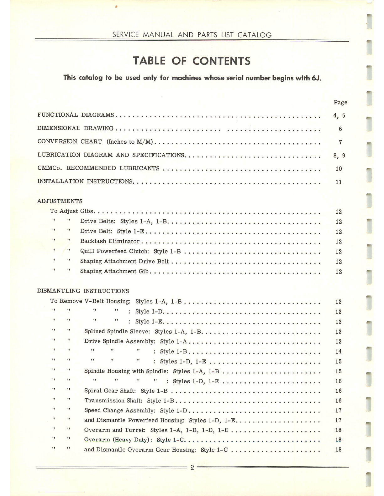
This catalog to be used
only
for machines
whose
serial
number
begins
with
6J.
FUNCTIONAL
DIAGRAMS
DIMENSIONAL
DRAWING
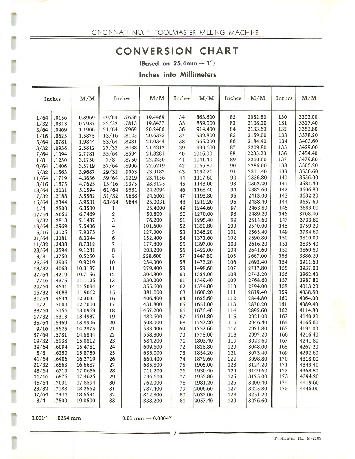
CONVERSION CHART
(InchestoM/M)
LUBRICATION
DIAGRAM
AND
SPECIFICATIONS.
CMMCo.
RECOMMENDED
LUBRICANTS
......
INSTALLATION
INSTRUCTIONS
ADJUSTMENTS
To
Adjust
Gibs
Drive
Belts:
Styles
1-A,
1-B.
. . .
Drive
Belt:
Style
1-E
" "
Backlash
Eliminator
"
Quill
Powerfeed
Clutch:
Style
1-B
" "
Shaping
Attachment
Drive
Belt
. . .
" "
Shaping
Attachment
Gib
DISMANTLING
INSTRUCTIONS
To
Remove
V-Belt
Housing
Styles
1-A,
1-B
Style
1-D
Style
1-E
Splined
Spindle
Sleeve:
Styles
1-A,
1-B.
. . . . . , . .
Drive
Spindle
Assembly:
Style
1-A
:
Style
1-B
:
Styles
1-D,
1-E
Spindle
Housing
with
Spindle:
Styles
1-A,
1-B
. . . .
" :
Styles
1-D,
1-E
...
.
Spiral
Gear
Shaft:
Style
1-B
Transmission
Shaft:
Style
1-B
Speed
Change
Assembly:
Style
1-D
and
Dismantle
Powerfeed
Housing:
Styles
1-D,
1-E.
Overarm
and
Turret:
Styles
1-A,
1-B,
1-D,
1-E
. .
Overarm
(Heavy
Duty):
Style
1-C.
and
Dismantle
Overarm
Gear
Housing:
Style
1-C
. .
Page
4,
5
6
7
8,
9
10
11
12
12
12
12
12
12
12
13
13
13
13
13
14
15
15
16
16
16
17
17
18
18
18
Page 4
CINCINNATI
NO.
1
TOOLMASTER
MILLING
MACHINE
To
Remove
Single
Swivel
Housing
Spindle
and
Drive
—
Without
Hand
Feed:
Style
1-C
" "
Single
Swivel
Housing
Spindle
and
Drive
—
With
Hand
Feed:
Style
1-C
. .
" "
and
Dismantle
Double
Swivel
Housing:
Style
1-C
Table
" "
Table
Leadscrew
" "
Table
Powerfeed
Housing
To
Dismantle
Table
Powerfeed
Housing
To
Remove
Standard
Saddle
" "
Crossfeed
Screw
" "
and
Dismantle
Saddle
When
TableIsEquipped
With
Powerfeed
" " " "
Saddle
Powerfeed
Housing
Elevating
Crank
Shaft
" "
Elevating
Screw
and
Pedestal
Knee
To
Dismantle
Shaping
Attachment
To
Install
Table
or
Saddle
Powerfeed
Motor
KEY
NUMBER
INDEX
HOW
TO
ORDER
REPAIR
PARTS
HIGH
SPEED
HEAD AND
OVERARM
(Unit
6JJR)....
HEAVY
DUTY
HEAD AND
OVERARM
(Unit
6JJS)
. . .
VARI-SPEED
HEAD AND OVERARM (Unit 6JKV). . . .
SADDLE-TABLE
(Unit
6JH)
KNEE (Unit 6JK)
COLUMN
(Unit
6JC)
COOLANT
PUMP
AND
PIPING
(Unit
6JP)
PRECISION MEASURING
EQUIPMENT
(Unit
6JJL).
. .
SHAPING
ATTACHMENT
(Unit
6JHF)
PLAIN,
SWIVEL AND UNIVERSAL VISES (Unit 6JKA)
INDEX
HEAD
AND
TAILSTOCK
(Unit
6JKA)
MACHINE
INSTRUCTION
PLATES
The
design
and
specifications
of
these
machines
are
subjecttochange
without
notice.
Page
18
19
19
19
20
20
21
21
22
22
22
23
23
24
24
24
25-26
27
29-41
43-53
55-67
69-77
79-89
91
91
93-95
97-99
101
103
105
Publication
No.
M-2109
Page 5
SERVICE
MANUAL
AND
PARTS
LIST
CATALOG
SPINDLE
DRIVE
MOTOR
TURRET
SWIVEL
LOCKING
NUTS
OVERARM
POSITIONING
PINION
SERIAL
NUMBER
PUSH
BUTTON
PANEL
TABLE
TRAVERSE
HANDWHEEL
KNEE
CLAMPS
SADDLE
CLAMP
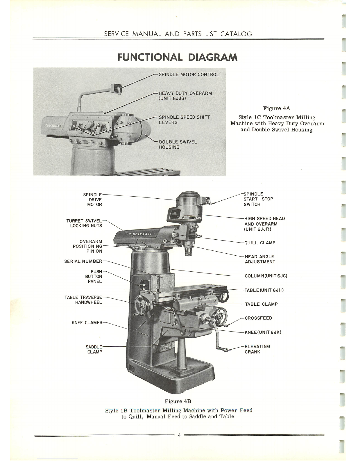
FUNCTIONAL
DIAGRAM
SPINDLE
MOTOR
CONTROL
HEAVY
DUTY
OVERARM
(UNIT6JJS)
SPINDLE
SPEED
SHIFT
LEVERS
DOUBLE
SWIVEL
HOUSING
Figure
4A
Style
1C
Toolmaster
Milling
Machine
with
Heavy
Duty
Overarm
and
Double
Swivel
Housing
PINDLE
START-STOP
SWITCH
HIGH
SPEED
HEAD
AND
OVERARM
(UNIT6JJR)
QUILL
CLAMP
HEAD
ANGLE
ADJUSTMENT
COLUMN(UNIT6JC)
TABLE
(UNIT
6JH)
TABLE
CLAMP
CROSSFEED
KNEE(UNIT6JK)
ELEVATING
CRANK
Figure
4B
Style
IB
Toolmaster
Milling
Machine
with
Power
Feed
to
Quill,
Manual
FeedtoSaddle
and
Table
Page 6
CINCINNATI
NO.
1
TOOLMASTER
MILLING
MACHINE
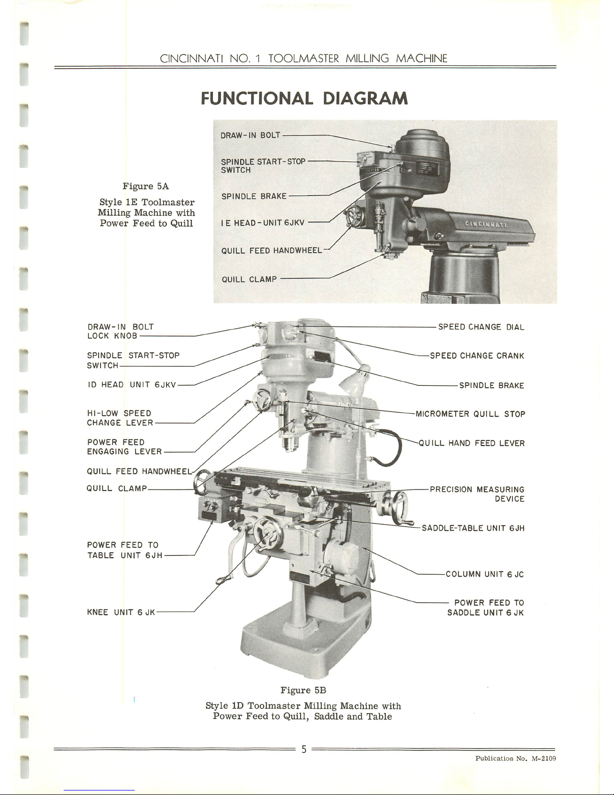
FUNCTIONAL
DIAGRAM
Figure
5A
Style
IE
Toolmaster
Milling
Machine
with
Power
Feed
to
Quill
DRAW-IN
BOLT
LOCK
KNOB
SPINDLE
START-STOP
SWITCH
ID
HEAD
UNIT
6JKV
HI-LOW
SPEED
CHANGE
LEVER
POWER
FEED
ENGAGING
LEVER
QUILL
FEED
HANDWHEEL-
QUILL
CLAMP
POWER
FEED
TO
TABLE
UNIT
6JH
KNEE
UNIT6JK
DRAW-IN
BOLT
SPINDLE
START-STOP
SWITCH
SPINDLE
BRAKE
IE
HEAD-UNIT
6JKV
QUILL
FEED
HANDWHEEL
QUILL
CLAMP
Figure
5B
Style
ID
Toolmaster
Milling
Machine
with
Power
FeedtoQuill,
Saddle
and
Table
Hi:
. \
SPEED
CHANGE
DIAL
SPEED
CHANGE
CRANK
SPINDLE
BRAKE
MICROMETER
QUILL
STOP
QUILL
HAND
FEED
LEVER
PRECISION
MEASURING
DEVICE
SADDLE-TABLE
UNIT
6JH
COLUMN
UNIT6JC
POWER
FEED
TO
SADDLE
UNIT
6JK
Publication
No.
M-2109
Page 7
SERVICE
MANUAL
AND
PARTS
LIST
CATALOG
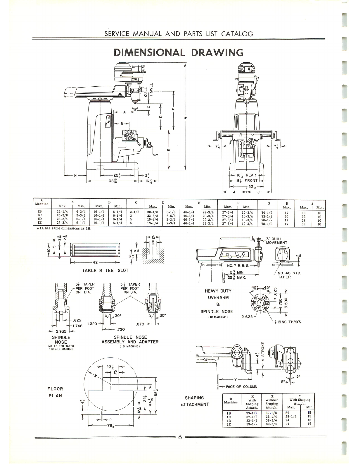
DIMENSIONAL
DRAWING
Machine
Max.
Min.
Max.
B
Min.
C
Max.
3
Min.
J
Max.
S
Min.
Max.
Min.
G
H
Max.
Max.IMin.
-
IB
1C
ID
IE
22-1/4
25-3/8
23-3/4
23-3/4
4-3/4
5-3/8
6-1/4
6-1/4
16-1/4
16-1/4
16-1/4
16-1/4
6-1/4
6-1/4
6-1/4
6-1/4
3-
3
5
5
1/2
20-1/8
22-5/8
19-3/4
19-3/4
3-1/8
5-5/8
2-3/4
2-3/4
46-3/4
46-3/4
46-3/4
46-3/4
29-3/4
29-3/4
29-3/4
29-3/4
27-3/4
27-3/4
27-3/4
27-3/4
10-3/4
10-3/4
10-3/4
10-3/4
74-1/2
73-1/2
78-1/2
78-1/2
17
20
17
17
32
32
32
32
10
10
10
10
*1Ahas
same
dimen.
ionsasIE
<•»
NO.40STD.
TAPER
(ID a IE
MACHINE)
FLOOR
PLAN
TABLE
a
TEE
SLOT
SPINDLE
NOSE
ASSEMBLY
AND
ADAPTER
( IB
MACHINE)
Ar
23^
-*-jll|
\
1
N
\
\
i
1 v
V 1
^
/
7
'i-
m
IO
ID
r
i_
^
1 -
i
— f i
r
^U-2
-*
78i
»~
1
Jx^J^i
^F^
NO.7b.as.
<5jMIN-
J
25 1 MAX.
HEAVY
DUTY
OVERARM
a
SPINDLE
NOSE
1IC
MACHINE)
2.625
SHAPING
ATTACHMENT
J.-13NC
THRD'S.
FACEOFCOLUMN
Machine
X
With
Shaping
Attach.
X
Without
Shaping
Attach.
With
S
Atta
Max.
Taping
ch.
Min.
IB
1C
ID
IE
33-1/2
37-1/8
33-1/2
33-1/2
37-1/8
38-1/4
39-3/4
39-3/4
24
28-1/2
24
24
15
15
15
15
Page 8
o
b
o
on
45.
O
b
3
3
ooo
45.
4=>
to
4i.
H-*
4=>
to
J>
CO
I—"
CO
Co
i-*
to
Co
i—'
NT
NT
h~i
to
NT
t—•
NT
H-»
i—•
i-.
•—.
m
co
•OJ
00
(n
1—i
to
i—*
*-*
en
to
to
-J
to
tn
-^t
CO
t—'
•—»
en
to
-OJ
•^J
OO
en
to
to
•-*
>—»
en
to
to
•^.l
i—'
cn
-J
OO
CO
M
en
to
H-»
-j
CO
cn
i—'
oo
1—1
I—i
\
\
~v
\
\ \ \
\
\ \ \ \ \
"V
-—
\
\
•"—,
*\
S
•^
•\
^^
\,
\.
\.
\^
\
\,
\
^
\
\^
\,
\
^
\,
*\
45.
Ol
to
fft
I—1
Ch
CO
(Ti
(TO
CT
co
Ol
H^
Ch
CO
Ch
NT
CT.
(o
Ch
1—i
CT,
CO
er
(XI
CT
CO
Ch
K-.
Ol
(o
o^
45.
CT,
co
Ch
1—'
CT
Co
CT
00
CT
OO
CT,
i—.
CT
OO
Ol
3
o
o-
<T>
-J
45.
to
45.
CT
4*
to
45.
45.
NT
4»
iDl
4i
NT
4^
4i
to
45.
CTi
45.
NT
45.
45.
to
45.
Ol
45.
NT
45.
45.
NT
45-
Ol
45.
to
45.
45.
NJ
45.
Ol
45.
NJ
45.
-0
~J
^1
Ch
Ch
or
Ch
Or
m
On
en
ejr
CJT
en
tn
cn
*.
45.
45.
45.
45.
45.
OO
Oo
CO
00
oo
CtJ
NT NT
NT
NT
NT
NT
NT
I—.
>-.
H-
h-'
1—'
H-'
o O
o o O
O
Cn
00
t—1
O
00
-J
on
45.
to
O
to
^j
CTl
4^
CO
i—*
O
00
(T,
en
CO
NT
O
to
-J
en
45.
NJ
I-*
to
(X)
CTl
en
CO
1—*
o
(TO
-o
cn
-(5-
to
O
to
^J
CT
45.
OO I—*
0)
O 45.
00
00
-J
i—i
Ol
O
en
to
CO
00
NT
<-^
i—•
en
e->
45-
on
CO
--.1
HI
CTi
o
tn
tn
to
oo
NT
CT,
H-»
en
O
45.
OO
to
-o
>—'
CT
O
On
to
0O
oo
NJ
Ol
1—1
On
o
5
oo
>—*
On
to
CO
Ch
O 45.
oo
H-'
On
to
CO
Or
O
45.
00
i—'
on
to
CO
Ch
O
-p.
00
i—.
C/l
to
Oo
CT
o 45.
00
I-.
On
to
OO
Ol
O
45.
00
i—.
cn
to
co
Ol
lO
00
co
^J
^0
-0
Ch
Ch
on on
On
45.
4^
CO
CO CO
to to
h-'
I—.
h-*
o O
to
to
to
00
oo
-J
•<]
-0
CT
CT
On
On
cn
45.
45.
CO
oo
CO
to
to
H-»
I—.
i-i
o
o
§
O
rr
NT
00
45.
o
Ch
to
OO
45.
e-r
CT,
NT
00
4*
O
-OJ
CO
to
en
h-*
-o
CO
to
CJl
i—,
•~J
CO
to
cn
H-1
^j
to
to
cn
I—.
^J
CO
to
On
t—1 •^T OO
to
cn
I—.
^T
Co
on
(/i
tn
en
cn
Ol
Ch
-J
•o.
-4
00
00
fX)
to to
to
O a
o
O
>-•
h-1
1-^
NT
to
ro
OO
0o
co
45.
45.
45.
en
On
cn cn
cn
CT
CT,
•^l
^t
•-J
00
oo
00
CO
to
to
~"\
O
CO
Ol
to
to
cn
00
i—•
en
0O
>—•
45.
•^J
e-r
to
Or
o
(o
CT.
to
NT
cn
CXI
1—.
C/l
oo
t-»
45.
^j
O
00
or
O
OO CT,
liJ
to
cn
oo
i—'
on
00
)-.
45.
-^J
o
OO
Ol
§
o
1-*
to
4>
On
Ch
^J
to
O
i—1
NT
4>
On
e^
•-]
to
o
h-*
to
45.
on
O-i
~J
to
o
H-*
NT
45.
cn
CT,
-J
to
o
H-*
NJ
45.
en
CT,
^j
to
O
t—'
NJ
-(5.
on
Ol
^J
to
<Tl
CO
CT,
k~»
en
ro
en
en
NJ
tn
i—i
cn
NJ
45.
CO
t—»
I—1
en
to to
^-t
--J
cn
^)
CO
OO
h-.
On
to
oo
00
00
CO
to
to
KT
to
NT
to
NT
NT
NT
NT
\
\
^^
\
—.
\^
-\
\
^s
*\
*-s^
^
*\
~v.
*\
Co
to
)—I
O
to
Of)
-0
Ol
en
45.
CO
NT
H-1
o
to
OS
^J
Ch
en
4i
CO
to
1—.
o
to
to
~J
CT
On
4>
OO
NT
1-^
(T
CO
Ch
K-1
CT
CO
CT,
oo
CT
OJ
OT
1—1
CT
OO
Ol
3
o
n
45.
NT
45.
o^
45.
to
45- 45.
NJ
45.
CT
45.
NJ
45.
to
to
to
tn
to
to
00
00
oo
00
00
00
•~o
^J
•~o
on
CTl
en
(O
NJ
a
to
^4
en
45.
NJ
1—1
tiJ
00
Ol
45.
00
to
•~o
M
Ch
O
cn
to
0J
(X)
NJ
OT
H-1
On
45.
00
h-»
cn
to
Oo
Ch
O 45-
CO
1—»
cn
to
OO
Ol
00
oo
-OJ
-o
o
*0J
Ch
Ch
Ch
CT
en
en
en
en
4i
•£>
4i
45.
to
CO
CO
(O
NT
ro
NT
NT
1—'
i—•
h-'
^—'
CO
00
or
CO
>—•
00
Ch
to
©
oo
en
CO
e-T
r»
en
00
O
00
en
(O
o
^J
cn
to
o
•^1
en
NJ
O
^J
en
NT
NT
NJ
NT
ro
NJ
ro
NJ
NJ
ro
NJ
NJ
NJ
NJ
1—1
h-i
00
to
*o.
to
Ch
M
On
CD
on
to
4*
OO
CO
CO
to
~J
\—>
em
I—.
<-n
o
45.
to
45.
cx>
CO
•~J
to
-~J
h-i
or
o
e-n
cn
45.
45.
oo
CO
OO
ro
NT
i—*
M
•—'
O
CJ
to
to
§
to
00
45.
r->
Ch
to
OO
4*
o
or
to
oo
4^
e-T
CTl
NT
t>0
45.
o
CT,
to
oo
45.
O
CT
NT
00
45.
O
Ch
NT
00
45. O
(T,
NT
on
45.
©
CT
n;
oo
45.
o
CT
NJ
00
45.
o
o o O ©
O
o o
o
<o
<o
o O O O
O
o
o
o O
e-T
o O O
o
o o
o
o o
o o
O
o
O
o
>—•
1—'
H-
NJ
NJ
NJ
OO
oo
CO
45.
45.
45.
^\.
o
©
o
o
o
o
o o o O O
o
o
o
o
o o
O
o
O
a o
a O
o
o O
O o O
o
o
o
CO
Ch
tn
NJ
On
OO
1—»
cn
00
I—.
45.
^1
e_> OO
Ol
g
o
1—.
NJ
45.
en
O-i
^J
to
o
I—1
NJ
45.
cn
Ol
to
00
00
•-0)
-o;
-J
-0.
-0
-o
~0
-OJ
~J
-o
o>
Ch
Ch
Ch
rr,
Ch
CT,
Ch
Ch
CT
cn cn
cn
cn
en
en
en
en
tn
en
45.
45.
45>
45.
4^
45.
45.
45.
45.
45- CO
OO
CO
oo
OO
00
>—i
3
n
t—*
o
to
00
•"J
Ol
On
4»
00
to
*-*
o
to
oo
-J
Ch
On
45- OO
NT
I—.
O
to
oo
•^J
Ch
cn
45.
CO
NT
>—•
o
to
00
-J
CT
cn
45.
OO
NJ
OJ
to
oo
Ol
cn
45.
3-
n
to
o
to
o
to
O
to
to
tn
to
oo
00
00
GO
•~J
-Oj
•OJ
-o
ch
(T.
CT,
CT,
en en
on
45.
45.
45.
45.
CO
to
co
to
NT NT
NT
NT
h->
h-.
(—*
)-*
o
o o
O
to to
to
to
co
00
On
00
<->
00
en
CO
o
-oj
en
to
O
^1
en
to
O
~~4
en
NT
o
^l
45.
NT
to
^o
45.
NT
to
^J
45.
NT
to
-0
45.
l—i
to
fT
45.
h-»
to
CT,
4f
i—1
to
Ul
oo
^
00
Ol
%
-0
to
Ch
1—*
On
o
on
to
4»>
00
OO
oo
to
-Ol
t-*
Ch
H-»
ejr
o
45.
to
45.
OO
OO
~J
NT
-0
I—1
CT, O
cn
O 45-
CO
CO
00
OO
-^1
NJ
Ol
}—•
0)1
c_>
on
to
45.
to
CO
45.
O
Ch
ro
00
4=»
O
Ol
to
oo
45.
o
CTl
NT
oo
4±
o
Ch
NT
00
45. O
or
NT
00
a
o
Ch
NT
00
45.
<n
CT
NT
OO
45.
O
CT
NT
00
45.
o
er
ro
00
45.
o
Oi
%
o
o
o
o o o
o
o o o O
o O
O o
O
o
o
o
o
O o o o
o
o o O
CT
o
O
o
O o
o
O o O O
e_)
e_)
e_J
e_)
o
e_)
O o
OJ
O o
o
o
to
to
to
to
to
NT
to
to
to
NT
O
e-T
o
o
O
o
o
O
rr
o
to
to
to
to
tn
to
tn
tn
to
to
oa
OO
oo
OO
CO
00
oo
oo
•—i
3
n
to
co
-J
cr
On
4*
oo
to
M o
to
00
^J
e^
CJl
42.
CO
to
,—'
o
to
00
^1
er
eji
45.
Oo
NT
h-«
o
to
CO
-J
CT,
On
45.
00
NT
O
to
oo
^j
Ul
Ul
45.
CO
to
3"
n>
CO
oo
00 00
CO
CO
00
CO
CO
to
CO
to
to
NT
NT
NT
NT
NT
ro
NT
NT
NT
NT
IO
NT
NT
NT
NT
NT
NT
NT
NT
NT
NT
N.
NT
NJ
NT
NT
NT
ro
NJ
to
NT
NT
NT
NT
to
ro
to
to
to
NT
M
1—i
1—'
O
O
n
o
tn
tn
tn
tn
(XT
(X)
(X)
00
•^J
^-1
-0
~J
Ch
CT
er
Ch
en
en
en
en
45.
45.
45.
45.
(O
Oo
OO
OO
NJ
NJ
NJ
1-^
h-•
i—i
o
§
-o.
Cn
to
o
•OJ
45.
to
to
-oj
45.
NT
tn
•»)
4^
NT
to
•-4
4=>
>—'
to
IT,
45*
1—>
tn
en
45.
•-»
ten
CT
-P.
M
oo
Ch
CO
1—»
00
Ch
CO
K
on
Ol
OJ
O
00
on
OJ
e_J
00
Ol
\-*
On
o
On
to
45.
00
CO
oo
NT
•~j
i—»
Ch
H-*
on
O
J>
to
45.
(50
CO
-o
to
^j
H-»
eTi
o
cn
O
4>
to
CO
00
CO
•^1
NT
or
H^
or
c_J
to
45.
tu
Oo
OO
"^
Ol
to
00
45.
O
Ol
ro
00
45.
o
Ch
ro
oo
4*
o
Ch
NT
00
45.
O
Ch
NT
ca
-P^
c
en
NT
oo
45.
e-T
CT
NT
00
45.
e-r
CT
NT
00
45.
o
er
NT
00
45.
o
CT
NT
00
§
o
o O O o
o
o o O
o
o
o o o o
O
O o
O
O
o
O o o
o
o
o
o O O
O o
o O
O O
O
o
o
o
OJ
OJ
t_l
t_l
e-J
o
-J
-OJ
-J
-J
-J
»a
rn
Ch
Ch
Ch
(T.
Ch
Ch
Ch
Ch
CT.
cn
en
en
en en
cn
Ol
en
en
en
45.
45.
.J>
45.
45.
45.
45.
45.
45.
45.
CO
CO
CO
to
CjJ
OJ
OO
CjJ
OO CO
3
Cn
45.
Oo
to
H^
o
to
oo
^j
Ch
On
-f^
OO
to
1—'
o CO
00
-J
CTi
cn
45.
00
to
H-.
o
to
OO
-o
Ol
on
45.
U)
NT
!—•
c_>
to
oo
u,
45.
OJ
i—i
©
3"
CA
..!>
*>
J>
45.
45.
4*
45.
45. 45.
4*
4^
4^
4^
4i.
4i
45.
45.
45.
co
CO
(.jj
CO
oo
CO
CO
co
to
CO
co
OO
00
OO
CO
OO
OO
CO
OJ
CO
co
CO
CO
CO
00
CjJ
0O
oo
4>
45.
to
(O
00
CO
to
ro
NT
NT
t—'
i—1
t-*
t—'
O O O
O
to
tn to
to
00
(XI
oo
<X1
-.1
^l
•^i
^)
er
Ch Ch
CT
en
cn
cn
cn
45.
4^
45.
-15.
oo
0o
g
45.
to
Ol
45. I—1
to
oi
45.
1—«
to
CTl
J>
H-
(»
Ol
00
(-.
(TO
Ch
CO
•-'
00
en
CO
i—•
oo
en
CO
o
oo
en
CO
O
(XI
cn
OJ
o
NJ
o
CJl
NJ
o
On
to
45.
00 00
oo
to
~o
t—•
Ch
M
eji
o
4^
to
4*
00
OO
-J
NT
^J
V-«
CT,
o
On
o
45.
to
CO
oo
OO
~J
NT
CT
1—*
O-i
o
cn
to
4^
to
CjJ
oo
£
O
m
NT
00
45.
e->
Ch
NT
no
4±
O
ai
NT
00
4^.
O CT,
NT
00
45.
O
n\
NT
00
45. o
CT
NT
on
455.
(->
Ol
ro
00
45-
o
CT
to
oo
45.
O
CT,
NJ
00
45.
o
o o o o o o ©
O
o O
O
o O
O O
O O
O o o o
o
o
o
o
o
O
O
o
O
O
o o
o
O
o
O
C-J
t_j
OJ
0J
O
c_>
OJ
l_T
o
3
00
n a
• S^
u>
"-
— O
3 3
O
K>
= 3
|
II
O
to
n
>
7*
n
znz
z
>
O
O
O
>
o
>
o
Page 9
SERVICE
MANUAL
AND
PARTS
LIST
CATALOG
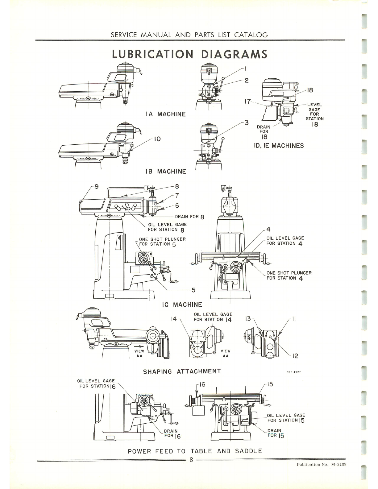
LUBRICATION
DIAGRAMS
OIL
LEVEL
GAGE
FOR
STATION
|6
IC
MACHINE
OIL
LEVEL
GAGE
FOR STATION
|4
SHAPING
ATTACHMENT
16
POWER
FEED
TO
TABLE
AND
SADDLE
OIL
LEVEL
GAGE
FOR
STATION
4
ONE
SHOT
PLUNGER
FOR
STATION
4
OIL
LEVEL
GAGE
FOR STATION
|5
Publication
No.
M-2109
Page 10
CINCINNATI
NO.
1
TOOLMASTER
MILLING
MACHINE
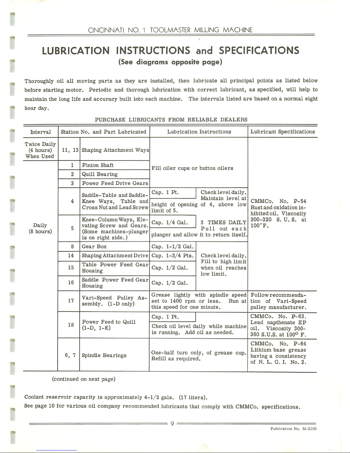
LUBRICATION
INSTRUCTIONS
and
SPECIFICATIONS
(See
diagrams
opposite
page)
Thoroughly
oil
all
moving
parts
as
they
are
installed,
then
lubricate
all
principal
points
as
listed
below
before
starting
motor.
Periodic
and
thorough
lubrication
with
correct
lubricant,
as
specified,
will
help
to
maintain
the
long
life
and
accuracy
built
into
each
machine.
The
intervals
listed
are
based
onanormal
eight
hour
day.
PURCHASE
LUBRICANTS
FROM
RELIABLE
DEALERS
Interval
Twice
Daily
(4
hours)
When
Used
Daily
(8
hours)
Station
No.
and
Part
Lubricated
11,
13
14
15
16
17
18
6,
7
Shaping
Attachment
Ways
Pinion
Shaft
Quill
Bearing
Power
Feed
Drive
Gears
Saddle-Table
and
Saddle-
Knee
Ways,
Table
and
Cross
Nut
and
Lead
Screw
Knee-Column
Ways,
Ele
vating
Screw
and
Gears.
(Some
machines-plunger
isonright
side
„)
Gear
Box
Shaping
Attachment
Drive
Table
Power
Feed
Gear
Housing
Saddle
Power
Feed
Gear
Housing
Vari-Speed
Pulley
As
sembly.
(1-D
only)
Power
Feed
to
Quill
(1-D,
1-E)
Spindle
Bearings
Lubrication
Instructions
Fill
oiler
cupsorbutton
oilers
Cap.1Pt.
Check
level
daily.
Maintain
level
at
height
of
opening
of
4,
above
low
limit
of
5.
Cap.
1/4
Gal.
Cap.
1-1/2
Gal.
Cap.
1-3/4
Pts.
Cap.
1/2
Gal.
Cap.
1/2
Gal.
3
TIMES
DAILY
Pull
out
each
plunger
and
allowitto
return
itself.
Check
level
daily.
Fill
to
high
limit
when
oil
reaches
low
limit.
Grease
lightly
with
spindle
speed
set
to
1400
rpm
or
less.
Run
at
this
speed
for
one
minute.
Cap.1Pt.
Check
oil
level
daily
while
machine
is
running.
Add
oilasneeded.
One-half
turn
only,
of
grease
cup,
Refill
as
required.
Lubricant
Specifications
CMMCo.
No.
P-54
Rust
and
oxidation
in
hibited
oil.
Viscosity
300-320
S.U.S.
at
100°F.
Follow
recommenda
tion
of
Vari-Speed
pulley
manufacturer.
CMMCo.
No.
P-63.
Lead
napthenate
EP
oil.
Viscosity
300-
360
S.U.S.at100°
F.
CMMCo.
No.
P-64
Lithium
base
grease
havingaconsistency
of
N.
L.
G.
I.
No.
2.
(continued on next page)
Coolant
reservoir
capacityisapproximately
4-1/2
gals.
(17
liters).
See page 10
for
various
oil
company
recommended
lubricants
that
comply with CMMCo.
specifications.
9
Publication
No.
M-2109
Page 11
SERVICE
MANUAL
AND
PARTS LIST
CATALOG
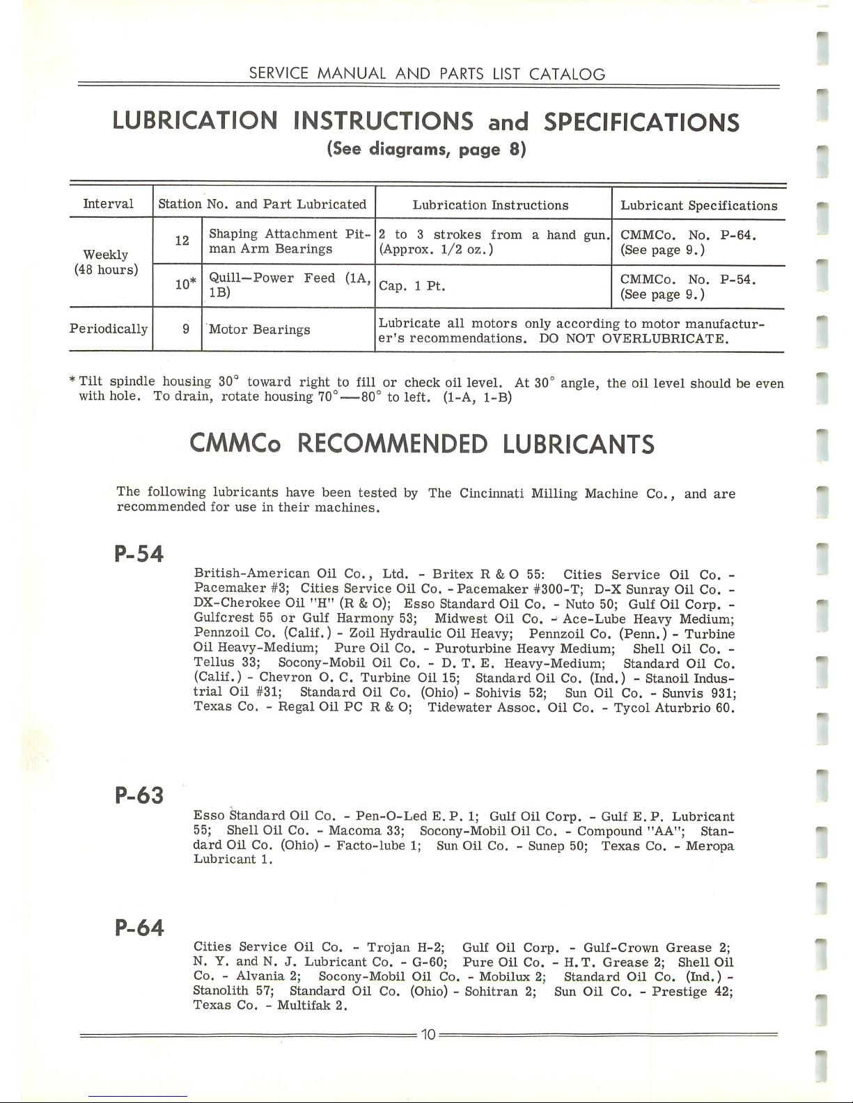
LUBRICATION
INSTRUCTIONS
and
SPECIFICATIONS
(See
diagrams,
page
8)
Interval
Station
No.
and
Part
Lubricated
Lubrication
Instructions
Lubricant
Specifications
Weekly
12
Shaping
Attachment
Pit
man
Arm
Bearings
2 to 3
strokes
from
a
hand
gun.
(Approx.
1/2
oz.)
CMMCo.
No.
P-64.
(See
page
9.)
(48
hours)
10*
Quill—Power
Feed
(1A,
IB)
Cap.1Pt.
CMMCo.
No.
P-54.
(See
page
9.)
Periodically
9
Motor
Bearings
Lubricate
all
motors
only
according
to
motor
manufactur
er's
recommendations.
DO
NOT
OVERLUBRICATE.
*Tilt
spindle housing 30° toward right to fill or check oil level. At 30° angle, the oil level should be even
with hole. To drain,
rotate
housing
70°—80°
to left. (1-A, 1-B)
CMMCo
RECOMMENDED
LUBRICANTS
The
following
lubricants
have
been
tested
by The Cincinnati Milling Machine Co.
recommended
for
useintheir
machines.
and
are
P-54
P-63
P-64
British-American
Oil
Co.,
Ltd.-Britex
R & O 55:
Cities
Service
Oil
Co.
-
Pacemaker
#3;
Cities
Service
Oil Co.
-Pacemaker
#300-T; D-X Sunray Oil Co. -
DX-Cherokee Oil "H" (R &O);
Esso
Standard Oil Co. - Nuto 50; Gulf Oil Corp. -
Gulfcrest
55
or
Gulf Harmony 53; Midwest Oil Co. -
Ace-Lube
Heavy Medium;
Pennzoil Co. (Calif.) - Zoil Hydraulic Oil Heavy; Pennzoil Co. (Penn.) - Turbine
Oil
Heavy-Medium;
Pure
Oil
Co. -
Puroturbine
Heavy Medium;
Tellus
33;
Socony-Mobil
Oil
Co. - D.T.E.
Heavy-Medium;
(Calif.) - Chevron O. C. Turbine Oil 15; Standard Oil Co. (Ind
trial
Oil
#31;
Standard
Oil Co. (Ohio) - Sohivis 52; Sun
Oil
Shell
Oil
Co.
-
Standard
Oil
Co.
) -
Stanoil
Indus-
Co.-Sunvis
931;
Texas
Co. -
Regal
Oil
PC
R & O;
Tidewater
Assoc.
Oil
Co.-Tycol
Aturbrio
60.
Esso
Standard
Oil
Co.-Pen-O-Led
E.P.1; Gulf
Oil
Corp.
- Gulf E.P.Lubricant
55;
Shell
Oil
Co. -
Macoma
33;
Socony-Mobil
Oil
Co. -
Compound
"AA";
Stan
dard
Oil Co. (Ohio) -
Facto-lube
1; Sun Oil Co. - Sunep 50;
Texas
Co. -
Meropa
Lubricant
1.
Cities
Service
Oil
Co.-Trojan
H-2;
N. Y.
andN.J.
Lubricant
Co.-G-60;
Co.-Alvania
2;
Socony-Mobil
Oil
Co.-Mobilux
2
Stanolith
57;
Standard
Oil
Co. (Ohio) -
Sohitran
2;
Texas
Co.-Multifak
2.
10
=
Gulf
Oil
Corp.
-
Gulf-Crown
Grease
2;
Pure
Oil
Co.-H.T.
Grease
2;
Shell
Oil
Standard
Oil
Co.
(Ind.)
-
Sun
Oil
Co.-Prestige
42;
Page 12
CINCINNATI
NO.
1
TOOLMASTER
MILLING
MACHINE
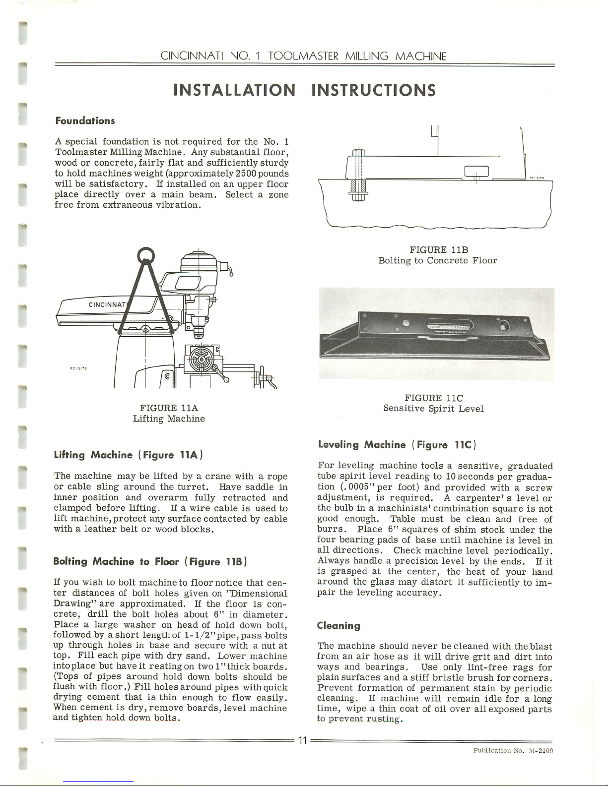
INSTALLATION
INSTRUCTIONS
Foundations
A
special
foundation
is
not
required
for
the
No.
1
Toolmaster
Milling
Machine.
Any
substantial
floor,
woodorconcrete,
fairly
flat
and
sufficiently
sturdy
to
hold
machines
weight
(approximately
2500
pounds
willbesatisfactory.
If
installed
onanupper
floor
place
directly
overamain
beam.
Select
a
zone
free
from
extraneous
vibration.
FIGURE
11A
Lifting
Machine
Lifting Machine (Figure 11A)
The
machine
maybelifted
byacrane
witharope
or
cable
sling
around
the
turret.
Have
saddle
in
inner
position
and
overarm
fully
retracted
and
clamped
before
lifting.
If a
wire
cable
is
used
to
lift
machine,
protect
any
surface
contacted
by
cable
withaleather
belt
or
wood
blocks.
Bolting
Machine
to Floor (Figure TIB)
If
you
wishtobolt
machinetofloor
notice
that
cen
ter
distances
of
bolt
holes
given
on
"Dimensional
Drawing"
are
approximated.
If
the
floor
is
con
crete,
drill
the
bolt
holes
about
6"
in
diameter.
Placealarge
washer
on
headofhold
down
bolt,
followedbya
short
lengthof1-1/2"pipe,
pass
bolts
up
through
holes
in
base
and
secure
withanut
at
top.
Fill
each
pipe
with
dry
sand.
Lower
machine
into
place
but
haveitresting
on
two
l"thick
boards.
(Topsofpipes
around
hold
down
bolts
should
be
flush
with
floor.)
Fill
holes
around
pipes
with
quick
drying
cement
thatisthin
enough
to flow
easily.
When
cementisdry,
remove
boards,
level
machine
and
tighten
hold
down
bolts.
11
FIGURE
11B
Bolting
to
Concrete
Floor
FIGURE
11C
Sensitive
Spirit
Level
Leveling Machine (Figure TIC)
For
leveling
machine
toolsasensitive,
graduated
tube
spirit
level
reading
to 10
seconds
per
gradua
tion
(.0005"
per
foot)
and
provided
withascrew
adjustment,
is
required.
A
carpenter'
s
level
or
the
bulbina
machinists'
combination
squareisnot
good
enough.
Table
must
be
clean
and
free
of
burrs.
Place
6"
squares
of
shim
stock
under
the
four
bearing
pads
of
base
until
machineislevel
in
all
directions.
Check
machine
level
periodically.
Always
handleaprecision
level
by
the
ends.
If
it
is
grasped
at
the
center,
the
heat
of
your
hand
around
the
glass
may
distort
it
sufficientlytoim
pair
the
leveling
accuracy.
Cleaning
The
machine
should
never
be
cleaned
with
the
blast
fromanair
hose
asitwill
drive
grit
and
dirt
into
ways
and
bearings.
Use
only
lint-free
rags
for
plain
surfaces
andastiff
bristle
brush
for
corners.
Prevent
formation
of
permanent
stain
by
periodic
cleaning.
If
machine
will
remain
idle
foralong
time,
wipeathin
coatofoil
over
all
exposed
parts
to
prevent
rusting.
Publication
No.
M-2109
Page 13
SERVICE
MANUAL
AND
PARTS
LIST
CATALOG
ADJUSTMENTS
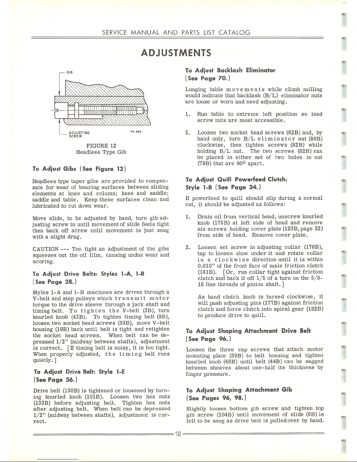
FIGURE
12
Headless
Type
Gib
To
Adjust
Gibs
(See
Figure 12)
Headless
type
taper
gibs
are
provided
to
compen
sate
for
wear
of
bearing
surfaces
between
sliding
elements
at
knee
and
column;
knee
and
saddle;
saddle
and
table.
Keep
these
surfaces
clean
and
lubricated
to
cut
down
wear.
Move
slide,
to
be
adjusted
by
hand,
turn
gib
ad
justing
screwinuntil
movementofslide
feels
tight
then
back
off
screw
until
movement
is
just
snug
withaslight
drag.
CAUTION
—
Too
tight
an
adjustment
of
the
gibs
squeezes
out
the
oil
film,
causing
undue
wear
and
scoring.
To
Adjust
Drive Belts: Styles 1-A, 1-B
(See
Page
28.)
Styles
1-A
and
1-B
machines
are
driven
through
a
V-belt
and
step
pulleys
which
transmit
motor
torquetothe
drive
sleeve
throughajack
shaft
and
timing
belt.
To
tighten
the
V-belt
(3B),
turn
knurled
knob (43B). To
tighten
timing
belt
(9B),
loosen
two
socket
head
screws
(33B),
move
V-belt
housing
(19B)
back
until
beltistight
and
retighten
the
socket
head
screws.
When
belt
can
be
de
pressed
1/2"
(midway
between
shafts),
adjustment
is
correct.
[If
timing
beltisnoisy,itis too tight.
When
properly
adjusted,
the
timing
belt
runs
quietly.]
To
Adjust
Drive Belt:
Style
1-E
(See Page 56.)
Drive
belt
(130B)istightened
or
loosened
by
turn
ing
knurled
knob
(101B).
Loosen
two
hex
nuts
(133B)
before
adjusting
belt.
Tighten
hex
nuts
after
adjusting
belt.
When
belt
can
be
depressed
1/2"
(midway
between
shafts),
adjustment
is
cor
rect.
To
Adjust
Backlash Eliminator
(See Page 70.)
Lunging
table
movements
while
climb
milling
would
indicate
that
backlash
(B/L)
eliminator
nuts
are
loose
or
worn
and
need
adjusting.
1.
Run
table
to
extreme
left
position
so
lead
screw
nuts
are
most
accessible.
2.
Loosen
two
socket
head
screws
(82B)
and,
by
hand
only,
turn
B/L
eliminator
nut
(80B)
clockwise,
then
tighten
screws
(82B)
while
holding
B/L
nut.
The
two
screws
(82B)
can
be
placed
in
either
set
of
two
holes
in
nut
(79B)
that
are
90°
apart.
To
Adjust
Quill
Powerfeed
Clutch:
Style 1-B (See Page 34.)
If
powerfeed
to
quill
should
slip
duringanormal
cut,itshouldbeadjusted
as
follows:
1.
Drain
oil
from
vertical
head,
unscrew
knurled
knob
(175B)atleft
side
of
head
and
remove
six
screws
holding
cover
plate
(123B,page
32)
from
side
of
head.
Remove
cover
plate.
2.
Loosen
set
screw
in
adjusting
collar
(178B),
taptoloosen
shoe
underitand
rotate
collar
in
a
clockwise
direction
until
itiswithin
0.010"
of
the
front
face
of
male
friction
clutch
(181B).
[Or,
run
collar
tight
against
friction
clutch
and
backitoff
1/5
of a
turnonthe
5/8-
18 fine
threads
of pinion
shaft.
]
As
hand
clutch
knob
is
turned
clockwise,
it
will
push
adjusting
pins
(177B)
against
friction
clutch
and
force
clutch
into
spiral
gear
(182B)
to
produce
drivetoquill.
To Adjust Shaping
Attachment
Drive Belt
(See Page
96.)
Loosen
the
three
cap
screws
that
attach
motor
mounting
plate
(39B)tobelt
housing
and
tighten
knurled
knob
(48B)
until
belt
(44B)
can
be
sagged
between
sheaves
about
one-half
its
thickness
by
finger
pressure.
To Adjust Shaping Attachment Gib
(See Pages 96, 98.)
Slightly
loosen
bottom
gib
screw
and
tighten
top
gib
screw
(104B) until movement of slide (8B)
is
felttobe
snugasdrive
beltispulled
overbyhand.
=
12
Page 14
CINCINNATI
NO.1TOOLMASTER
MILLING
MACHINE
DISMANTLING
PROCEDURE
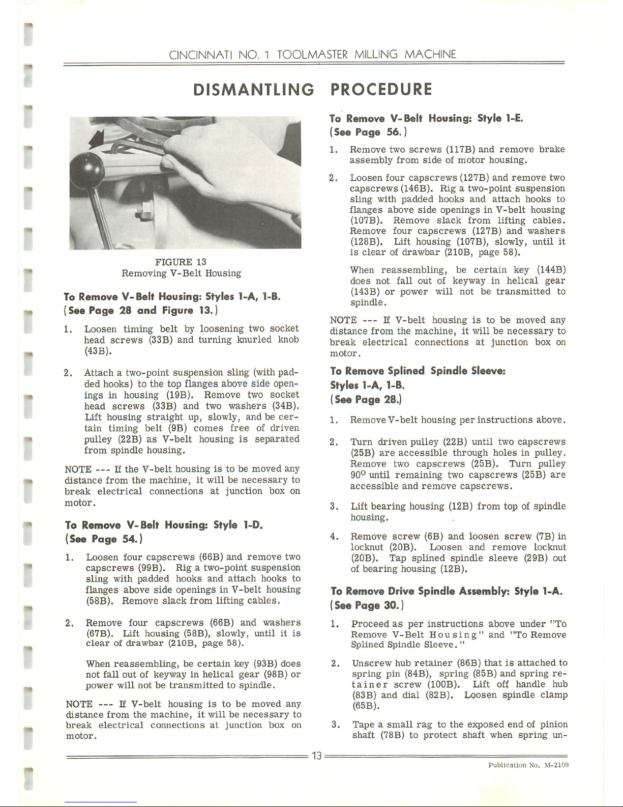
FIGURE
13
Removing
V-Belt
Housing
To
Remove
V-Belt
Housing:
Styles
1-A,
1-B.
(See
Page 28
and
Figure 13.)
1.
Loosen
timing
belt
by
loosening
two
socket
head
screws
(33B)
and
turning
knurled
knob
(43B).
2. Attach a
two-point
suspension
sling (with pad
ded
hooks)tothe
top
flanges
above
side
open
ings
in
housing
(19B).
Remove
two
socket
head
screws
(33B)
and
two
washers
(34B).
Lift
housing
straight
up,
slowly,
andbecer
tain
timing
belt
(9B)
comes
free
of
driven
pulley
(22B)
as
V-belt
housing
is
separated
from
spindle
housing.
NOTE
— If
the
V-belt
housingistobemoved
any
distance
from
the
machine,itwillbenecessary
to
break
electrical
connections
at
junction
box
on
motor.
To
Remove
V-Belt
Housing:
Style
1-D.
(See Page 54.)
1.
Loosen
four
capscrews
(66B)
and
remove
two
capscrews
(99B).
Rigatwo-point
suspension
sling
with
padded
hooks
and
attach
hooks
to
flanges
above
side
openingsinV-belt
housing
(58B).
Remove
slack
from
lifting
cables.
2.
Remove
four
capscrews
(66B)
and
washers
(67B).
Lift
housing
(58B),
slowly,
untilitis
clear
of
drawbar
(210B,
page
58).
When
reassembling,
be
certain
key
(93B)
does
not
fall
outofkeywayinhelical
gear
(98B)
or
power
will
notbetransmitted
to
spindle.
NOTE
— If
V-belt
housing
is
to
be
moved
any
distance
from
the
machine,
it
willbenecessary
to
break
electrical
connections
at
junction
box
on
motor.
13:
To
Remove
V-Belt
Housing:
Style
1-E.
(See
Page
56.)
1.
Remove
two
screws
(117B)
and
remove
brake
assembly
from
sideofmotor
housing.
2.
Loosen
four
capscrews
(127B)
and
remove
two
capscrews
(146B).
Rigatwo-point
suspension
sling
with
padded
hooks
and
attach
hooks
to
flanges
above
side
openings
in
V-belt
housing
(107B).
Remove
slack
from
lifting
cables.
Remove
four
capscrews
(127B)
and
washers
(128B).
Lift
housing
(107B),
slowly,
until
it
is
clearofdrawbar
(210B,
page
58).
When
reassembling,
be
certain
key
(144B)
does
not
fall
out
of
keyway
in
helical
gear
(143B)orpower
will
not
be
transmitted
to
spindle.
NOTE
— If
V-belt
housing
is
to
be
moved
any
distance
from
the
machine,
it
willbenecessary
to
break
electrical
connections
at
junction
box
on
motor.
To
Remove
Splined Spindle
Sleeve:
Styles 1-A, 1-B.
(See Page 28.)
1.
Remove
V-belt
housing
per
instructions
above.
2.
Turn
driven
pulley
(22B)
until
two
capscrews
(25B)
are
accessible
through
holesinpulley.
Remove
two
capscrews
(25B).
Turn
pulley
90°
until
remaining
two
capscrews
(25B)
are
accessible
and
remove
capscrews.
3.
Lift
bearing
housing
(12B)
from
topofspindle
housing.
4.
Remove
screw
(6B)
and
loosen
screw
(7B)
in
locknut
(20B).
Loosen
and
remove
locknut
(20B).
Tap
splined
spindle
sleeve
(29B)
out
of
bearing
housing
(12B).
To
Remove
Drive
Spindle
Assembly:
Style
1-A.
(See Page 30.)
1.
Proceed
as
per
instructions
above
under
"To
Remove
V-Belt
Housing"
and
"To
Remove
Splined
Spindle
Sleeve.
"
2.
Unscrew
hub
retainer
(86B)
thatisattached
to
spring
pin
(84B),
spring
(85B)
and
spring
re
tain
er
screw
(100B).
Lift
off
handle
hub
(83B)
and
dial
(82B).
Loosen
spindle
clamp
(65B).
3.
Tapeasmall
rag
to
the
exposed
endofpinion
shaft
(78B)toprotect
shaft
when
spring
un-
Publication
No.
M-2109
Page 15
SERVICE
MANUAL
AND
PARTS LIST
CATALOG
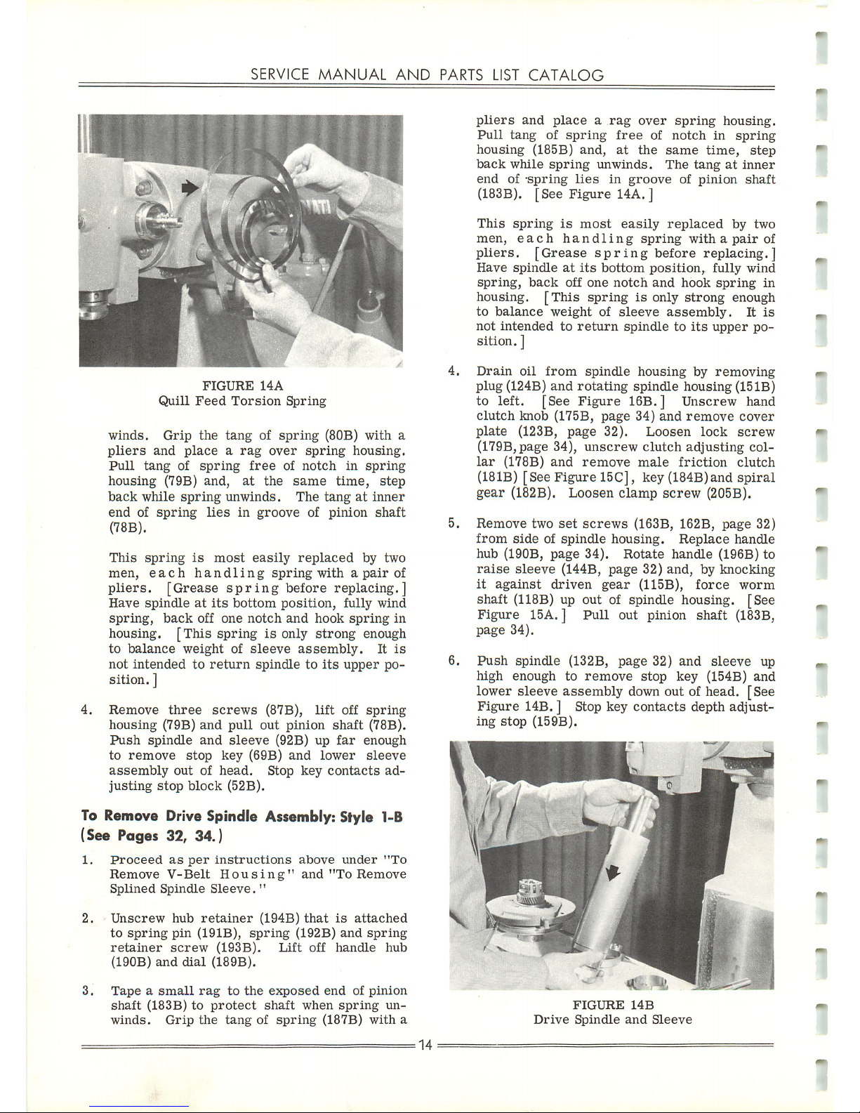
FIGURE
14A
Quill
Feed
Torsion
Spring
winds.
Grip
the
tangofspring
(80B) with a
pliers
and
placearag
over
spring
housing.
Pull
tang
of
spring
free
of
notch
in
spring
housing
(79B)
and,
at
the
same
time,
step
back
while
spring
unwinds.
The
tangatinner
endofspring
lies
in
groove
of
pinion
shaft
(78B).
This
spring
is
most
easily
replaced
by
two
men,
each
handling
spring
withapair
of
pliers.
[Grease
spring
before replacing.]
Have
spindleatits
bottom
position,
fully
wind
spring,
back
off
one
notch
and
hook
spring
in
housing.
[This
springisonly
strong
enough
to
balance
weight
of
sleeve
assembly.
It
is
not
intendedtoreturn
spindletoits
upper
po
sition. ]
4.
Remove
three
screws
(87B),
lift
off
spring
housing
(79B)
and
pull
out
pinion
shaft
(78B).
Push
spindle
and
sleeve
(92B) up
far
enough
to
remove
stop
key
(69B)
and
lower
sleeve
assembly
out
of
head.
Stop
key
contacts
ad
justing
stop
block
(52B).
To
Remove
Drive Spindle
Assembly:
Style 1-B
(See Pages 32, 34.)
1.
Proceed
as
per
instructions
above
under
"To
Remove
V-Belt
Housing"
and
"To
Remove
Splined
Spindle
Sleeve."
2.
Unscrew
hub
retainer
(194B)
that
is
attached
to
spring
pin
(191B),
spring
(192B)
and
spring
retainer
screw
(193B).
Lift
off
handle
hub
(190B)
and
dial
(189B).
3.
Tapeasmall
rag
to
the
exposed
endofpinion
shaft
(183B)toprotect
shaft
when
spring
un
winds.
Grip
the
tangofspring
(187B)
with
a
=
14
pliers
and
placearag
over
spring
housing.
Pull
tang
of
spring
free
of
notch
in
spring
housing
(185B)
and,
at
the
same
time,
step
back
while
spring
unwinds.
The
tangatinner
endof-spring
lies
in
groove
of
pinion
shaft
(183B). [See
Figure
14A. ]
This
spring
is
most
easily
replaced
by
two
men,
each
handling
spring
withapair
of
pliers.
[Grease
spring
before
replacing.]
Have
spindleatits
bottom
position,
fully
wind
spring,
back
off
one
notch
and
hook
spring
in
housing.
[This
springisonly
strong
enough
to
balance
weight
of
sleeve
assembly.
It
is
not
intended
to
return
spindletoits
upper
po
sition.
]
Drain
oil
from
spindle
housing
by
removing
plug (124B)
and
rotating
spindle
housing (15
IB)
to left. [See
Figure
16B.] Unscrew hand
clutch
knob (175B,
page
34)
and
remove
cover
plate
(123B,
page
32).
Loosen
lock
screw
(179B,page 34),
unscrew
clutch
adjusting
col
lar
(178B)
and
remove
male
friction
clutch
(181B)
[See Figure 15C], key (184B)and
spiral
gear
(182B). Loosen
clamp
screw
(205B).
Remove
two
set
screws
(163B, 162B,
page
32)
from
sideofspindle
housing.
Replace
handle
hub (190B, page 34).
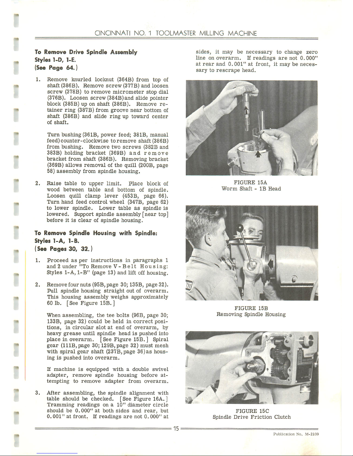
Rotate
handle (196B) to
raise
sleeve
(144B, page 32) and, by knocking
it
against
driven
gear
(115B),
force
worm
shaft
(118B)
up out of spindle housing. [See
Figure 15A. ] Pull out pinion shaft (183B,
page
34).
Push
spindle (132B,
page
32)
and
sleeve
up
high
enough
to
remove
stop
key
(154B)
and
lower sleeve
assembly
down out of head. [See
Figure
14B. ] Stop key contacts depth adjust
ing
stop
(159B).
FIGURE
14B
Drive
Spindle
and
Sleeve
Page 16
CINCINNATI
NO.
1
TOOLMASTER
MILLING
MACHINE
To
Remove
Drive
Spindle
Assembly
Styles
1-D, 1-E.
(See Page 64.)
1.
Remove
knurled
locknut
(364B)
from
top of
shaft
(386B).
Remove
screw
(377B)
and
loosen
screw
(378B) to
remove
micrometer
stop
dial
(376B).
Loosen
screw
(384B)and
slide
pointer
block
(385B) up on
shaft
(386B).
Remove
re
tainer
ring
(387B)
from
groove
near
bottom
of
shaft
(386B)
and
slide
ring
up
toward
center
of
shaft.
Turn
bushing
(361B,
power
feed;
381B,
manual
feed)counter-clockwise
toremove
shaft
(386B)
from
bushing.
Remove
two
screws
(382B
and
383B)
holding
bracket
(369B)
and
remove
bracket
from
shaft
(386B).
Removing
bracket
(369B)
allows
removal
of the quill (200B, page
58)
assembly
from
spindle
housing.
2.
Raise
table
to
upper
limit.
Place
block
of
wood
between
table
and
bottom
of
spindle.
Loosen
quill
clamp
lever
(453B,
page
66).
Turn
hand
feed
control
wheel
(347B,
page
62)
to
lower
spindle.
Lower
table
as
spindle
is
lowered. Support spindle
assembly
[near
top]
beforeitis
clear
of
spindle
housing.
To
Remove
Spindle
Housing
with
Spindle:
Styles
1-A,
1-B.
(See Pages 30,
32.)
1.
Proceed
as
per
instructions
in
paragraphs
1
and2under
"To
Remove
V-Belt
Housing:
Styles 1-A,
1-B"
(page 13) and
lift
off housing.
2.
Remove
four
nuts
(95B,page
30; 135B,
page
32).
Pull
spindle
housing
straight
outofoverarm.
This
housing
assembly
weighs
approximately
60 lb. [See Figure 15B.]
When
assembling,
the
tee
bolts
(96B,
page
30;
133B,
page
32)
couldbeheldincorrect
posi
tions,
in
circular
slot
at
endofoverarm,
by
heavy
grease
until
spindle
headispushed
into
place in
overarm.
[See
Figure
15B.] Spiral
gear
(11
IB,
page
30;
129B,page
32)
must
mesh
with
spiral
gear
shaft
(237B,page
36)ashous
ingispushed
into
overarm.
If
machine
is
equipped
withadouble
swivel
adapter,
remove
spindle
housing
before
at
tempting
to
remove
adapter
from
overarm.
3.
After
assembling,
the
spindle
alignment
with
table
should be
checked.
[See
Figure
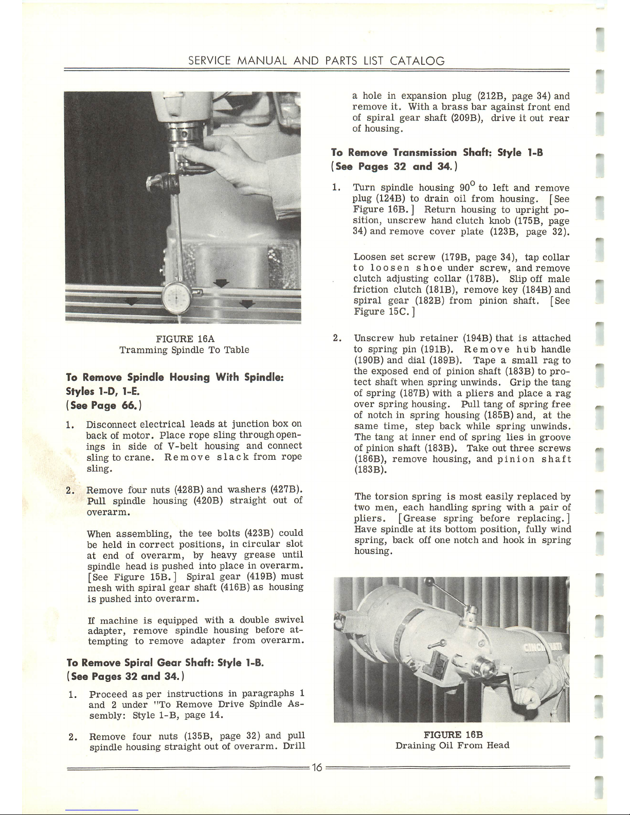
16A. ]
Tramming
readings
ona10"
diameter
circle
should
be
0.000"
at
both
sides
and
rear,
but
0.001"
at
front.
If
readings
are
not
0.000"
at
15
sides,
it
may
be
necessary
to
change
zero
line
on
overarm.
If
readings
are
not
0.000"
at
rear
and
0.001"
at
front,itmaybeneces
sarytorescrape
head.
FIGURE
15A
Worm
Shaft-IB
Head
FIGURE
15B
Removing
Spindle
Housing
FIGURE
15C
Spindle
Drive
Friction
Clutch
Publication
No.
M-2109
Page 17
SERVICE
MANUAL
AND
PARTS
LIST
CATALOG
FIGURE
16A
Tramming
Spindle
To
Table
To
Remove
Spindle
Housing
With
Spindle:
Styles
1-D, 1-E.
(See Page 66.)
1,
Disconnect
electrical
leadsatjunction
box
on
backofmotor.
Place
rope
sling
through
open
ings
in
sideofV-belt
housing
and
connect
slingtocrane.
Remove
slack
from
rope
sling.
2. Remove four
nuts
(428B)
and
washers
(427B).
Pull
spindle
housing
(420B)
straight
out
of
overarm.
When
assembling,
the
tee
bolts
(423B) could
be
heldincorrect
positions,
in
circular
slot
at
end
of
overarm,
by
heavy
grease
until
spindle
headispushed
into
placeinoverarm.
[See Figure 15B.] Spiral gear
(419B)
must
mesh
with
spiral
gear
shaft
(416B)ashousing
is
pushed
into
overarm.
If
machine
is
equipped
withadouble
swivel
adapter,
remove
spindle
housing
before
at
tempting
to
remove
adapter
from
overarm.
To
Remove
Spiral
Gear
Shaft:
Style
1-B.
(See
Pages32and
34.)
1.
Proceed
as
per
instructions
in
paragraphs
1
and2under
"To
Remove
Drive
Spindle
As
sembly:
Style
1-B,
page
14.
2.
Remove
four
nuts
(135B,
page
32)
and
pull
spindle housing
straight
out of
overarm.
Drill
=
16
a
holeinexpansion
plug
(212B,
page
34)
and
remove
it.
Withabrass
bar
against
front
end
of
spiral
gear
shaft
(209B),
driveitout
rear
of
housing.
To
Remove
Transmission
Shaft:
Style
1-B
(See Pages 32
and
34.)
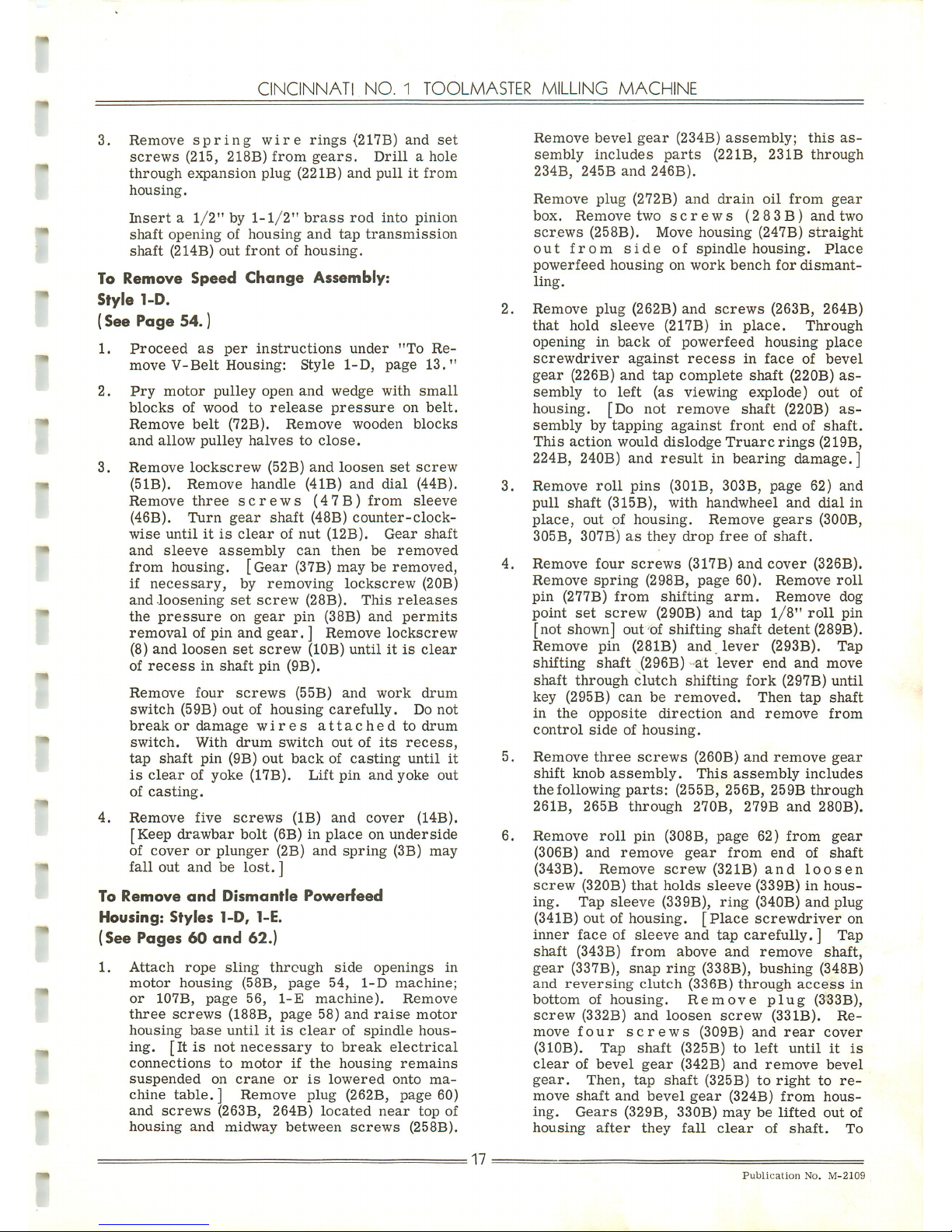
1.
Turn
spindle
housing
90°
to left and
remove
plug
(124B)
to drain oil from housing. [See
Figure
16B. ] Return housing to upright po
sition,
unscrew
hand
clutch
knob
(175B,
page
34) and
remove
cover
plate
(123B, page 32).
Loosen
set
screw
(179B,
page
34),
tap
collar
to
loosen
shoe
under
screw,
and
remove
clutch
adjusting
collar
(178B). Slip off
male
friction
clutch
(18IB),
remove
key
(184B)
and
spiral
gear
(182B)
from
pinion shaft. [See
Figure
15C.]
2.
Unscrew
hub
retainer
(194B)
that
is
attached
to
spring
pin
(191B).
Remove
hub
handle
(190B)
and
dial
(189B).
Tapeasmall
rag
to
the
exposed
endofpinion
shaft
(183B)topro
tect
shaft
when
spring
unwinds.
Grip
the
tang
of
spring
(187B)
withapliers
and
placearag
over
spring
housing.
Pull
tangofspring
free
of
notchinspring
housing
(185B)
and,
at
the
same
time,
step
back
while
spring
unwinds.
The
tangatinner
endofspring
liesingroove
of
pinion
shaft
(183B).
Take
out
three
screws
(186B),
remove
housing,
and
pinion
shaft
(183B).
The
torsion
spring
is
most
easily
replaced
by
two
men,
each
handling
spring
withapair
of
pliers.
[Grease
spring
before
replacing.]
Have
spindle
at
its
bottom
position,
fully
wind
spring,
back
off
one
notch
and
hookinspring
housing.
r~*mi
FIGURE
16B
Draining
Oil
From
Head
Page 18
CINCINNATI
NO.
1
TOOLMASTER
MILLING
MACHINE
3.
Remove
spring
wire
rings
(217B)
and
set
screws
(215,
218B)
from
gears.
Drillahole
through
expansion
plug
(22IB)
and
pullitfrom
housing.
Inserta1/2"by1-1/2"
brass
rod
into
pinion
shaft
opening
of
housing
and
tap
transmission
shaft
(214B)
out
frontofhousing.
To
Remove
Speed
Change
Assembly:
Style
1-D.
(See Page 54.)
1.
Proceed
as
per
instructions
under
"To
Re
move
V-Belt
Housing:
Style
1-D,
page
13."
2.
Pry
motor
pulley
open
and
wedge
with
small
blocks
of
wood
to
release
pressure
on
belt.
Remove
belt
(72B).
Remove
wooden
blocks
and
allow
pulley
halves
to
close.
3.
Remove
lockscrew
(52B)
and
loosen
set
screw
(51B).
Remove
handle
(41B)
and
dial
(44B).
Remove
three
screws
(47B)
from
sleeve
(46B).
Turn
gear
shaft
(48B)
counter-clock
wise
untilitis
clear
of
nut
(12B).
Gear
shaft
and
sleeve
assembly
can
then
be
removed
from housing.
[Gear
(37B)
may be removed,
if
necessary,
by
removing
lockscrew
(20B)
and
loosening
set
screw
(28B).
This
releases
the
pressure
on
gear
pin
(38B)
and
permits
removal of pin and
gear.
] Remove lockscrew
(8)
and
loosen
set
screw
(10B)
untilitis
clear
of
recess
in
shaft
pin
(9B).
Remove
four
screws
(55B)
and
work
drum
switch
(59B)
outofhousing
carefully.
Do
not
break
or
damage
wires
attached
to
drum
switch.
With
drum
switch
outofits
recess,
tap
shaft
pin
(9B)
out
backofcasting
until
it
is
clear
of
yoke
(17B).
Lift
pin
and
yoke
out
of
casting.
4.
Remove
five
screws
(IB)
and
cover
(14B).
[Keep drawbar bolt (6B) in place on underside
of
coverorplunger
(2B)
and
spring
(3B)
may
fall out and be
lost.
]
To
Remove
and
Dismantle
Powerfeed
Housing:
Styles
1-D, 1-E.
(See Pages 60
and
62.)
1.
Attach
rope
sling
through
side
openings
in
motor
housing
(58B,
page
54,
1-D
machine;
or
107B,
page
56,
1-E
machine).
Remove
three
screws
(188B,
page
58)
and
raise
motor
housing
base
untilitis
clear
of
spindle
hous
ing.
[Itisnot
necessary
to
break
electrical
connections
to
motor
if
the
housing
remains
suspended
on
crane
or
is
lowered
onto
ma
chine
table.]
Remove plug (262B, page 60)
and
screws
(263B,
264B)
located
near
top
of
housing
and
midway
between
screws
(258B).
.17
Remove
bevel
gear
(234B)
assembly;
this
as
sembly
includes
parts
(221B,
231B
through
234B,
245B
and
246B).
Remove
plug
(272B)
and
drain
oil
from
gear
box.
Remove
two
screws
(283B)
and
two
screws
(258B). Move
housing
(247B)
straight
out
from
side
of
spindle
housing.
Place
powerfeed
housing
on
work
bench
for
dismant
ling.
Remove
plug
(262B)
and
screws
(263B, 264B)
that
hold
sleeve
(217B) in
place.
Through
opening
in
back
of
powerfeed
housing
place
screwdriver
against
recess
in
face
of
bevel
gear
(226B)
and
tap
complete
shaft
(220B)
as
sembly
to
left
(as
viewing
explode)
out
of
housing. [Do not remove shaft (220B) as
sembly
by
tapping
against
front
endofshaft.
This
action
would
dislodge
Truarc
rings
(219B,
224B, 240B) and
result
in
bearing
damage.]
Remove
roll
pins
(301B,
303B,
page
62)
and
pull
shaft
(315B),
with
handwheel
and
dial
in
place,
outofhousing.
Remove
gears
(300B,
305B,
307B)asthey
drop
freeofshaft.
Remove
four
screws
(317B)
and
cover
(326B).
Remove
spring
(298B,
page
60).
Remove
roll
pin
(277B)
from
shifting
arm.
Remove
dog
point
set
screw
(290B)
and
tap
1/8"
roll
pin
[not shown] out of shifting shaft detent (289B).
Remove
pin
(281B)
and
lever
(293B).
Tap
shifting
shaft
(296B)
at
lever
end
and
move
shaft
through
clutch
shifting
fork
(297B)
until
key
(295B)
can
be
removed.
Then
tap
shaft
in
the
opposite
direction
and
remove
from
control
sideofhousing.
Remove
three
screws
(260B)
and
remove
gear
shift
knob
assembly.
This
assembly
includes
the
following
parts:
(255B,
256B,
259B
through
261B,
265B
through
270B,
279B
and
280B).
Remove
roll
pin
(308B,
page
62)
from
gear
(306B)
and
remove
gear
from
end
of
shaft
(343B).
Remove
screw
(321B)
and
loosen
screw
(320B)
that
holds
sleeve
(339B)inhous
ing.
Tap
sleeve
(339B),
ring
(340B)
and
plug
(341B) out of housing.
[Place
screwdriver
on
inner face of sleeve and tap
carefully.
] Tap
shaft
(343B)
from
above
and
remove
shaft,
gear
(337B),
snap
ring
(338B),
bushing
(348B)
and
reversing
clutch
(336B)
through
access
in
bottom
of
housing.
Remove
plug
(333B),
screw
(332B)
and
loosen
screw
(331B).
Re
move
four
screws
(309B)
and
rear
cover
(310B).
Tap
shaft
(325B)toleft
until
it
is
clear
of
bevel
gear
(342B)
and
remove
bevel
gear.
Then,
tap
shaft
(325B)toright
to
re
move
shaft
and
bevel
gear
(324B)
from
hous
ing.
Gears
(329B,
330B)
maybelifted
out
of
housing
after
they
fall
clear
of
shaft.
To
Publication
No.
M-2109
Page 19
SERVICE
MANUAL
AND
PARTS
LIST
CATALOG
separate
cluster
gear
from
driving
gear,
re
move
ring
(328B).
7.
Remove
screw
(248B,
page
60)
and
loosen
screw
(249B). Remove
roll
pin (250B). Tap
shaft
(253B)
from
inside
housing. As
shaftisre
moved,itwill
force
plug
(254B)
outofhousing.
To
Remove
Overarm
and
Turret:
Styles
1-A,
1-B, 1-D
and
1-E.
(See Pages 36
and
66.)
1.
Attach
rope
sling
through
side
openings
in
motor
housing
in
head
and
connect
sling
to
crane.
Remove
slack
from
sling.
Remove
four
nuts
from
T-bolts
that
hold
headtoover
arm
and
pull
head
straight
out
from
overarm.
2.
Remove
coolant
hose
(27B,
page
90)
and
brac
ket
(23B) if
machineisso equipped. Remove
socket
head
screw
from
top
center
of
over
arm,
insert
an
eyebolt
and
attach
crane
hook.
Wind
overarm
forward
and
slide
out
of
turret
(257B,
page
36).
Make
certain
overarm
is
balanced
asitis
slid
off, to
prevent
damage
to
ways.
Break
electrical
connections,
re
move
four
nuts
(255B)
from
topofturret
and
lift
turret
off
column.
NOTE
—
The
overarm
is
easier
to
balance
while
removing
if
spindle
housing
is
taken
off
first.
However,
by
usingarope
sling
around
spindle
housing
and
fromitto
crane,
itispossibletore
move
overarm
with
housinginplace.
To
Remove
Overarm (Heavy Duty):Style 1-C.
(See Page 42.)
Remove one
1/2"
set
screw
(2B)
from
top of
gear
housing (14B) on
motor
end,
insert
an
eyebolt
and
attach
to a
crane.
Remove
electrical
compartment
cover
(10B)
and
break
electrical
connections.
Wind
overarm
forward
and
slide
out
of
turret.
Make
certain
overarm
is
balanced
as
it
is
slid
off,
otherwise
vee-wayinturret
maybedamaged.
If a
double
swivel
housing
is
being
used,
turn
spindle
housing
soitis
in
line
with
overarm
to
preventatwisting
action
as
overarm
is
removed.
Itisadvisable
to
use
two
eyebolts
in
gear
case
when
lifting
overarm
with
swivel
housing
in
place.
To
Remove
and
Dismantle
Overarm
Gear
Housing:
Style
1-C
(See Pages 42, 44, 46)
1.
Drain
oil
from
gear
housing.
Set
the
center
and
rear
speed
shift
levers
(74B,
68B,page
44)
in
the
number2stops
and
the
forward
lever
(88B)ineither
its
number1or
its
neutral
stop.
Remove
twelve
screws
(5IB)
and
pull
speed
control
plate
(56B)from
overarm.
Mark
=
18
locationofgears
so
they
canbemore
easily
set
when
assembling.
2. Remove two
1/2"
set
screws
(2B, page 42),
insert
two
eyebolts
and
attach
toacrane.
Through
side
opening,
set
couplings (109B,
112B, page 46) so
their
sides
are
vertical,
re
move
fourteen
screws
(IB, 9B,
page
42),
and
raise
gear
housing
outofoverarm.
Overarm
can
be
left
on
turret
while
gear
housingisremoved
but
gear
housing
must
be
in
placetoremove
overarm.
3. Loosen
set
screw,
tap to loosen
lock
shoe,
remove
shoe-type
lock
nut
(148B,page
46)
and
drive
spur
gear
shaft
(142B)
toward
front
of
housing
sufficiently
to
expose
set
screw
in
lock nut (144B). Loosen
set
screw
and tap to
loosen
lock
shoeinnut.
Tap
shaft
(142B) to
rear
into
original
place
and,
usingaspanner
wrenchinthe
side
holes
of
nut
(144B), un
screw
it.
Tap
shaft
forward
and
outofhous
ing.
4. Remove
shoe-type
lock
nut
(137B),
loosen
locknut
(134B)
untilitis
clearofshaft
threads
and
tap
cluster
shaft
(13
IB)
forward
and
out
of
housing.
When
assembling,
set
spur
gear
(132B)
as
far
toward
rear
of
housing
as
possible
so
change
gear
(145B)
does
not
havetoshift
too
far
forward
to
engage
spur
gear
(132B).
If
change
gear
(145B)
moves
too
far
forward,
it
will
rub
against
end
of
change
gear
shaft
(119B).
5.
Remove
coupling
halves
(109B, 112B)
and
hy-
pro
keys
from
ends
of
change
gear
shafts
(105B, 119B).
Remove
shoe-type
locknuts
(108B, 115B)
and
tap
shafts
out
of
housing.
The
flangeofbearing
cup
(106B)
must
have
a
flat
ground
on
one
side
to
miss
the
adjacent
bearing.
To
Remove
Single
Swivel
Housing
Spindle
and
Drive
—Without
Hand Feed:
Style
1-C
(See Pages
44
and
50)
1.
Drain
oil
from
gear
housing.
Set
the
two
rear
speed
change
levers
(74B,
68B,
page
44)inthe
Number2stop
and
the
forward
lever
(88B) in
the
Number
1
stop.
Remove
twelve
screws
(51B)
and
pull
speed
control
plate
(56B)
from
overarm.
Itiseasier
to
align
couplings
when
assembling
if
speed
control
plateisoff.
2.
Unscrew
four
nuts
(211B,
page
50)
and
pull
spindle
housing
(213B)
from
overarm.
Re
move
index
head
gear
(235B)
from
sleeve
ad-
Page 20
CINCINNATI
NO.
1
TOOLMASTER
MILLING
MACHINE
justing
housing
(227B).
Remove
four
screws
(233B)
and
tap
motor
driven
shaft
(224B)
and
sleeve
housing
(227B)
assembly
outofspindle
housing.
After
assembly,
the
gear
(214B)iscorrectly
aligned
and
meshed
by
grinding
the
spacer
(207B)tocorrect
thickness.
3.
Remove
spindle
bearing
cap
(203B),
split
type
spindle
locknut
(205B)
from
topofspindle
and
spindle
cap
(220B)
from
bottom
of
spindle
housing.
Gently
tap
spindle
down
outofhousingtopre
vent
damage
to
thrust
bearing
(219B). It
is
not
necessary
to
remove
spindle
housing
be
fore
removing
spindle.
To
Remove
Single
Swivel
Housing
Spindle
and
Drive
—With
Hand Feed:
Style
1-C
(See Pages 48
and
50.)
This
spindle
housing
is
the
same
one
used
without
hand feed butisrotated
180° before mounting on
overarm.
(See
"Ref."at
bottomofpage
50.)
1.
Proceed
as
per
paragraphs
1
and2directly
above
under
"To
Remove
Single
Swivel
Hous
ing.
"When
assembling,
grind
spacer
(16
IB,
page
48) to
set
spiral
drive
gear
(153B) to
gearonmotor
driven
shaft
(224B,
page
50).
2.
Remove
two
screws
(17IB)
and
draw
bolt
cover
(191B).
Remove
bearing
nut
(193B)
and
locknut
(174B)
and
remove
quill
(169B)
from
spindle.
Loosen
set
screw
(154B)
and
tap
to
free
brass
plug
(155B)
under
it.
Unscrew
quill
adjusting
cap
(199B)
from
topofspindle
housing
and
remove
with
dial
(198B)
and
quill,
adjusting
screw
(184B).
3.
Remove
spindle
bearing
cap
(165B)
and
split
type
locknut
(163B)
from
bottom
of
spindle
(167B).
Turn
spindle housing 180° and gently
tap
spindle
(167B) down
outofhousingtopre
vent
damagetothrust
bearing
(149B).
To
Remove
and
Dismantle
Double
Swivel
Housing:
Style
1-C
(See
Page
52.)
1.
Remove
spindle
housing
(160B,
page
48
or
213B,
page
50)
from
double
swivel
housing
(260B,
page
52).
Remove
end
cap
(266B),
shoe-type
locknut
(265B)
and
tap
spiral
bevel
pinion
(240B)
gently
outofhousing.
If
pinion
is
driven
too
hard,
the
thrust
bearing
(243B)
might
be
damaged.
=
19-
2.
Remove
four
nuts
(258B)
and
pull
swivel
head
out
of
overarm.
Remove
index
head
gear
(247B). Remove
set
screw
(261B) and pull
eccentric
(262B)
from
housing.
Remove
set
screw
(250B),
loosen
set
screw
(25IB)
and
pull
motor
driven
shaft
(254B)
and
bearing
sleeve
(256B)
assembly
outofoverarm.
Remove
shoe-type
locknut
(244B)
and
gently
tap
shaft
outofsleeve
to
prevent
damaging
thrust
bearing
(255B).
3. When
assembling,
gear
(240B)
and
gear
on
motor
shaft
(254B)
are
aligned
by
grinding
spacer
(242B) to
suit
and
moving
bearing
sleeve
(256B) with
eccentric
(262B). Sight
gears
through
opening
left
by
removal
of
ex
pansion
plug
(249B). When
spindle
housing
(160Bor213B)isattachedtoswivel
housing,
it
may
be
necessary
to
readjust
all
gears
to
obtain
proper
running
mesh.
When
inserting
spindle
housinginswivel
housingorthe
latter
into
overarm,
turn
hous
ing 90° to one
side
before
slippingithome.
Thus,
if a
slight
loop
of
the
O-ring
gasket
should
be
squeezed
down
and
cut
by
edge
of
opening,
the
damaged
portion
will
be
above
lubrication
level.
To
Remove
Table
(See Page 68.)
1.
Unscrew
split
type
locknut
(38B)
from
right
endofleadscrew(2IB)
and
remove
handwheel
with
dial.
Remove
key
(22B),
four
cap
screws
(24B)
and
tap
right-hand
apron
(23B)
from
table.
2. Move
tabletorightsoleft
apronisnear
sad
dle.
Remove
four
cap
screws
(18B)
from
left
apron
and
tap
aprontofreeitfrom
table.
Remove
precision
measuring
equipment
from
table,ifso
equipped.
3.
FastenaU-clamp
to
center
of
table
and
at
tachtoa
crane
withaslight
tension.
Remove
gib (12B),
loosen
saddle
clamping
lever
(114B,
page
70)
and
slide
table
(11B)
toward
right
and
off
saddle.
If
tableisequipped
with
powerfeed,
itisfirst
necessary
to
remove
gear
housing
bracket
(144B,
page
72)
and
then
proceed
as
above.
Itisextremely
difficult
to
replace
an
apron
onto
leadscrew
without
damaging
the
oil
seal.
Itisbettertofirst
remove
seal,
install
apron
and
then
replace
seal.
Makearoll
of
thin
shim
stock,
slip
inside
seal,
put
shim
roll
on
endofscrew,
slide
seal
into
placeinapron
and
remove
shim
roll.
Publication
No.
M-2109
Page 21
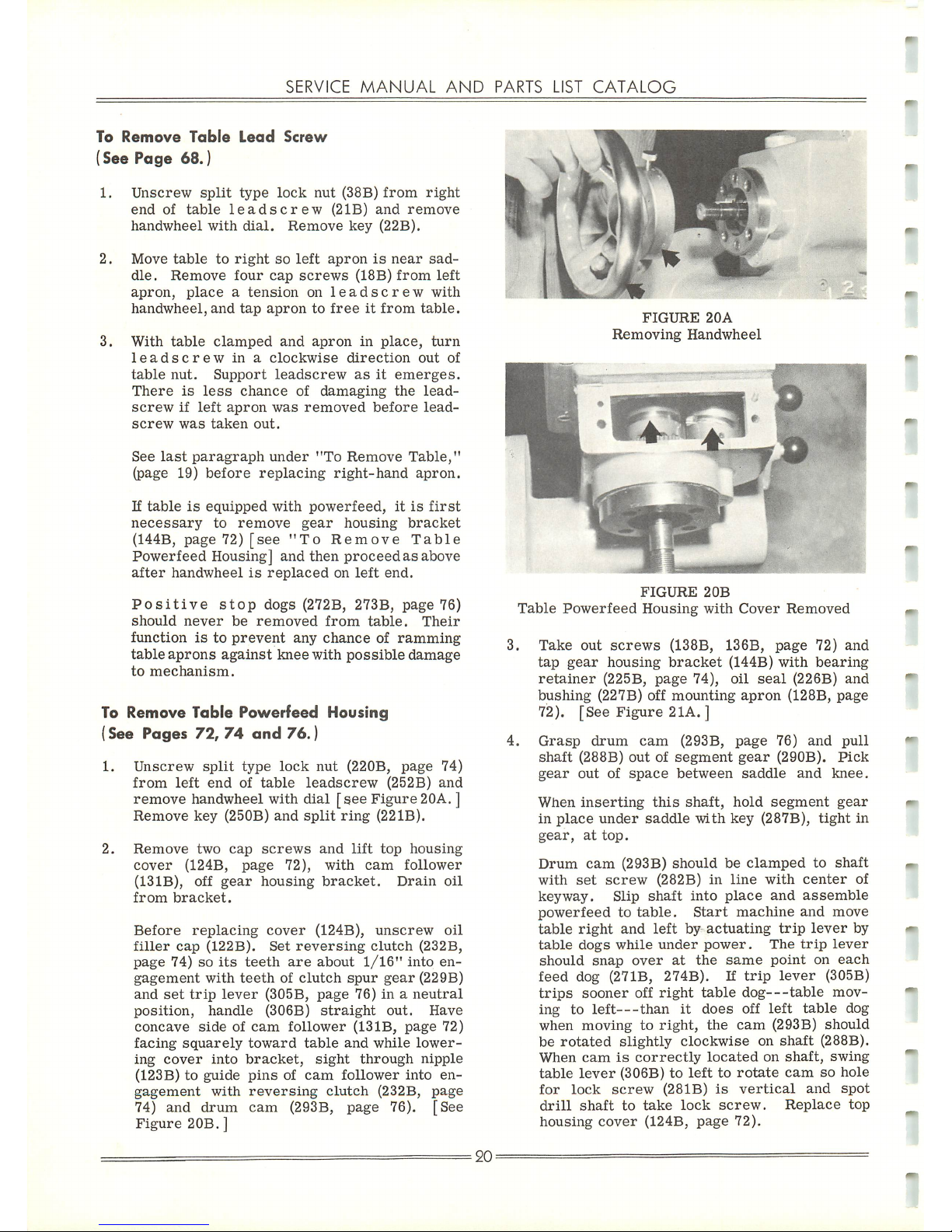
SERVICE
MANUAL
AND
PARTS
LIST
CATALOG
To
Remove
Table
Lead
Screw
(See Page 68.)
1.
Unscrew
split
type
lock
nut
(38B)
from
right
end
of
table
leadscrew
(2IB)
and
remove
handwheel
with
dial.
Remove
key
(22B).
2.
Move
table
to
right
so
left
apronisnear
sad
dle.
Remove
four
cap
screws
(18B)
from
left
apron,
placeatension
on
leadscrew
with
handwheel,
and
tap
aprontofreeitfrom
table.
3.
With
table
clamped
and
apron
in
place,
turn
leadscrew
inaclockwise
direction
out
of
table
nut.
Support
leadscrew
asitemerges.
There
is
less
chance
of
damaging
the
lead-
screwifleft
apron
was
removed
before
lead-
screw
was
taken
out.
See
last
paragraph
under
"To
Remove
Table,"
(page 19)
before
replacing
right-hand
apron.
If
tableisequipped
with
powerfeed,
itisfirst
necessary
to
remove
gear
housing
bracket
(144B, page 72)
[see
"To
Remove
Table
Powerfeed Housing] and then
proceed
as above
after
handwheelisreplaced
on
left
end.
Positive
stop
dogs
(272B,
273B,
page
76)
should
never
be
removed
from
table.
Their
functionisto
prevent
any
chance
of
ramming
table
aprons
against
knee
with
possible
damage
to
mechanism.
To
Remove
Table
Powerfeed
Housing
(See Pages
72,
74
and
76.)
1.
Unscrew
split
type
lock
nut
(220B,
page
74)
from
left
endoftable
leadscrew
(252B)
and
remove handwheel with dial
[see
Figure 20A.]
Remove
key
(250B)
and
split
ring
(221B).
2.
Remove
two
cap
screws
and
lift
top
housing
cover
(124B,
page
72),
with
cam
follower
(13IB),
off
gear
housing
bracket.
Drain
oil
from
bracket.
Before
replacing
cover
(124B),
unscrew
oil
filler
cap
(122B).
Set
reversing
clutch
(232B,
page
74) so
its
teeth
are
about
1/16"
into
en
gagement
with
teethofclutch
spur
gear
(229B)
and
set
trip
lever
(305B,
page
76)ina
neutral
position,
handle
(306B)
straight
out.
Have
concave
sideofcam
follower
(13IB,
page
72)
facing
squarely
toward
table
and
while
lower
ing
cover
into
bracket,
sight
through
nipple
(123B)toguide
pins
of
cam
follower
into
en
gagement
with
reversing
clutch
(232B,
page
74)
and
drum
cam
(293B, page 76). [See
Figure
20B.]
20:
FIGURE
20A
Removing
Handwheel
FIGURE2OB
Table
Powerfeed
Housing
with
Cover
Removed
3.
Take
out
screws
(138B, 136B,
page
72)
and
tap
gear
housing
bracket
(144B)
with
bearing
retainer
(225B,
page
74),
oil
seal
(226B)
and
bushing
(227B) off
mounting
apron
(128B,
page
72). [See
Figure
21A. ]
4.
Grasp
drum
cam
(293B,
page
76)
and
pull
shaft
(288B)
outofsegment
gear
(290B).
Pick
gear
outofspace
between
saddle
and
knee.
When
inserting
this
shaft,
hold
segment
gear
in
place
under
saddle
with
key
(287B),
tight
in
gear,
at
top.
Drum
cam
(293B)
should
be
clamped
to
shaft
with
set
screw
(282B)inline
with
center
of
keyway.
Slip
shaft
into
place
and
assemble
powerfeed
to
table.
Start
machine
and
move
table
right
and
left
by
actuating
trip
lever
by
table
dogs
while
under
power.
The
trip
lever
should
snap
over
at
the
same
point
on
each
feed
dog (27IB, 274B). If
trip
lever
(305B)
trips
sooner
off
right
table
dog—table
mov
ing
to
left—than
it
does
off
left
table
dog
when
movingtoright,
the
cam
(293B)
should
be
rotated
slightly
clockwise
on
shaft
(288B).
When
camiscorrectly
located
on
shaft,
swing
table
lever
(306B)tolefttorotate
camsohole
for
lock
screw
(281B)
is
vertical
and
spot
drill
shaft
to
take
lock
screw.
Replace
top
housing
cover
(124B,
page
72).
Page 22
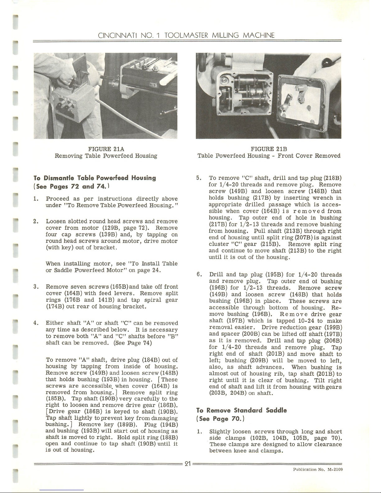
CINCINNATI
NO.
1
TOOLMASTER
MILLING
MACHINE
FIGURE
21A
Removing
Table
Powerfeed
Housing
To Dismantle
Table
Powerfeed
Housing
(See Pages
72
and
74.)
1.
Proceed
as
per
instructions
directly
above
under
"To
Remove
Table
Powerfeed
Housing.
"
2.
Loosen
slotted
round
head
screws
and
remove
cover
from
motor
(129B,
page
72).
Remove
four
cap
screws
(139B)
and,
by
tapping
on
round
head
screws
around
motor,
drive
motor
(with
key)
outofbracket.
When
installing
motor,
see
"To
Install
Table
or
Saddle
Powerfeed
Motor"
on
page
24.
3.
Remove
seven
screws
(165B)and
take
off
front
cover
(164B)
with
feed
levers.
Remove
split
rings
(176B
and
141B)
and
tap
spiral
gear
(174B)
out
rear
of
housing
bracket.
4.
Either
shaft
"A"
or
shaft
"C"
can
be
removed
any
time
as
described
below.
Itisnecessary
to
remove
both
"A"
and
"C"
shafts
before
"B"
shaft
canberemoved.
(See
Page
74)
To
remove
"A"
shaft,
drive
plug
(184B)
out
of
housing
by
tapping
from
inside
of
housing.
Remove
screw
(149B)
and
loosen
screw
(148B)
that
holds bushing (193B) in housing.
[These
screws
are
accessible,
when
cover
(164B)
is
removed
from
housing.]
Remove
split
ring
(185B).
Tap
shaft
(190B)
very
carefullytothe
right
to
loosen
and
remove
drive
gear
(186B).
[Drive
gear
(186B)iskeyed to shaft (190B).
Tap
shaft
lightlytoprevent
key
from
damaging
bushing.] Remove key (189B). Plug (194B)
and
bushing
(193B)
will
start
outofhousing
as
shaftismovedtoright.
Hold
split
ring
(188B)
open
and
continue
to
tap
shaft
(190B)
until
it
is
outofhousing.
21
FIGURE2IB
Table
Powerfeed
Housing-Front
Cover
Removed
5. To
remove
"C"
shaft,
drill
and
tap
plug
(218B)
for
1/4-20
threads
and
remove
plug.
Remove
screw
(149B)
and
loosen
screw
(148B)
that
holds
bushing
(217B) by
inserting
wrench
in
appropriate
drilled
passage
which
is
acces
sible
when
cover
(164B)
is
removed
from
housing.
Tap
outer
end
of
hole
in
bushing
(217B)
for
1/2-13
threads
and
remove
bushing
from
housing.
Pull
shaft
(213B)
through
right
endofhousing
until
split
ring
(207B)isagainst
cluster
"C"
gear
(215B).
Remove
split
ring
and
continuetomove
shaft
(213B)tothe
right
untilitis
outofthe
housing.
6.
Drill
and
tap
plug
(195B)
for
1/4-20
threads
and
remove
plug.
Tap
outer
endofbushing
(196B)
for
1/2-13
threads.
Remove
screw
(149B)
and
loosen
screw
(148B)
that
holds
bushing
(196B)inplace.
These
screws
are
accessible
through
bottom
of
housing.
Re
move
bushing
(196B).
Remove
drive
gear
shaft
(197B)
which
is
tapped
10-24
to
make
removal
easier.
Drive
reduction
gear
(199B)
and
spacer
(200B)
canbelifted
off
shaft
(197B)
asitis
removed.
Drill
and
tap
plug
(206B)
for
1/4-20
threads
and remove plug. Tap
right
end
of
shaft
(201B)
and
move
shaft
to
left; bushing (209B)
will
be
moved
to left,
also,
as
shaft
advances.
When
bushing
is
almost
outofhousing
rib,
tap
shaft
(20IB)
to
right
untilitis
clear
of
bushing.
Tilt
right
endofshaft
and
liftitfrom
housing
with
gears
(203B,
204B)onshaft.
To
Remove
Standard
Saddle
(See
Page
70.)
1.
Slightly
loosen
screws
through
long
and
short
side
clamps
(102B,
104B,
105B,
page
70).
These
clamps
are
designed
to
allow
clearance
between
knee
and
clamps.
Publication
No.
M-2109
Page 23
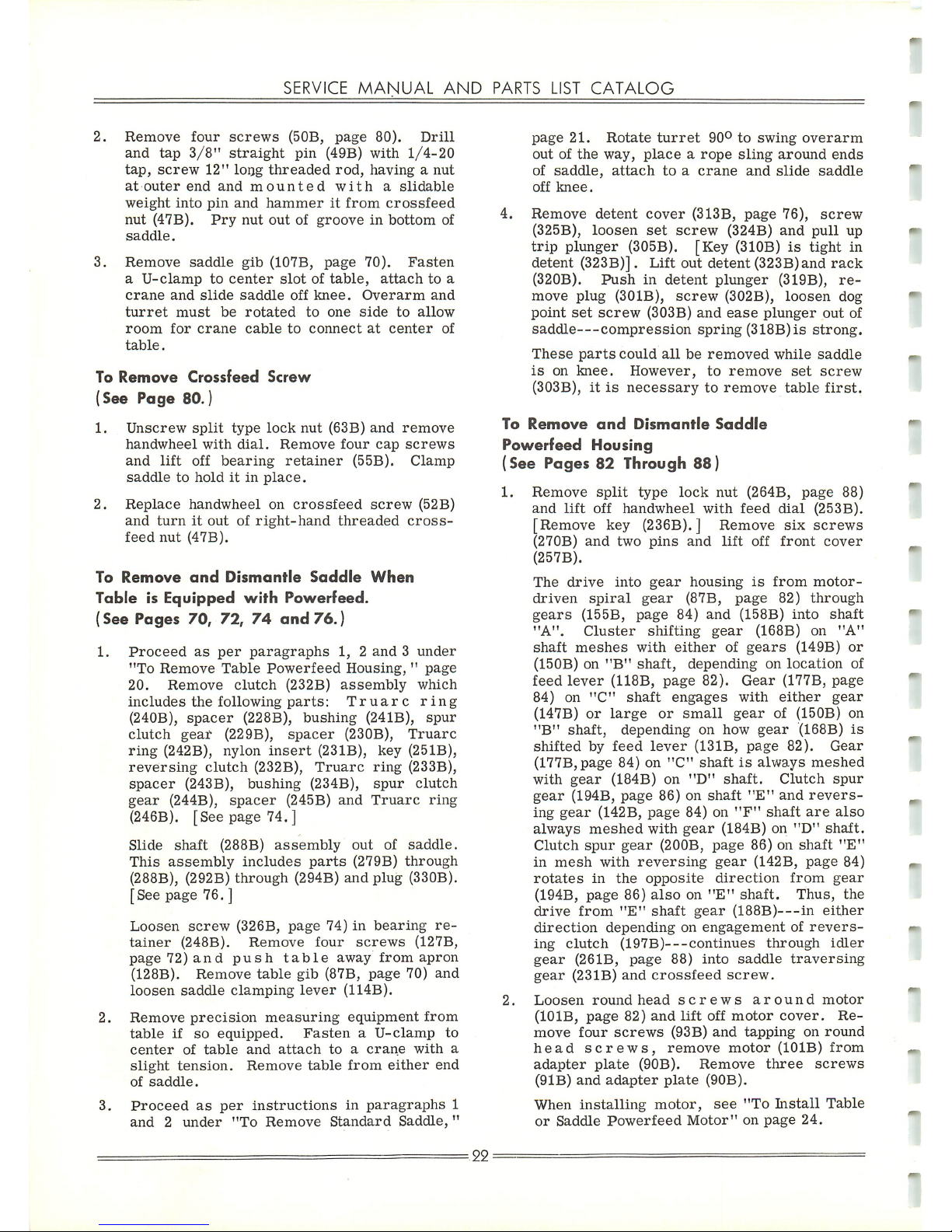
SERVICE
MANUAL
AND
PARTS
LIST
CATALOG
2.
Remove
four
screws
(50B,
page
80).
Drill
and
tap
3/8"
straight
pin
(49B)
with
1/4-20
tap,
screw
12"
long
threaded
rod,
havinganut
at
outer
end
and
mounted
with
a
slidable
weight
into
pin
and
hammer
it
from
crossfeed
nut
(47B).
Pry
nut
outofgrooveinbottom
of
saddle.
3.
Remove
saddle
gib
(107B,
page
70).
Fasten
a
U-clamp
to
center
slotoftable,
attach
to
a
crane
and
slide
saddle
off
knee.
Overarm
and
turret
must
be
rotated
to
one
side
to
allow
room
for
crane
cable
to
connect
at
center
of
table.
To
Remove
Crossfeed
Screw
(See Page 80.)
1.
Unscrew
split
type
lock
nut
(63B)
and
remove
handwheel
with
dial.
Remove
four
cap
screws
and
lift
off
bearing
retainer
(55B).
Clamp
saddle
to
holditin
place.
2.
Replace
handwheel
on
crossfeed
screw
(52B)
and
turnitoutofright-hand
threaded
cross-
feed
nut
(47B).
To
Remove
and
Dismantle
Saddle
When
Table is Equipped
with
Powerfeed.
(See
Pages
70, 72,
74
and
76.)
1.
Proceed
as
per
paragraphs
1, 2
and3under
"To
Remove
Table
Powerfeed
Housing,"page
20.
Remove
clutch
(232B)
assembly
which
includes
the
following
parts:
Truarc
ring
(240B),
spacer
(228B),
bushing
(24IB),
spur
clutch
gear
(229B),
spacer
(230B),
Truarc
ring
(242B),
nylon
insert
(231B),
key
(251B),
reversing
clutch
(232B),
Truarc
ring
(233B),
spacer
(243B),
bushing
(234B),
spur
clutch
gear
(244B),
spacer
(245B)
and
Truarc
ring
(246B). [See page
74.]
Slide
shaft
(288B)
assembly
out
of
saddle.
This
assembly
includes
parts
(279B)
through
(288B), (292B)
through
(294B)
and
plug
(330B).
[See page
76.]
Loosen
screw
(326B,
page
74)in
bearing
re
tainer
(248B).
Remove
four
screws
(127B,
page
72)
and
push
table
away
from
apron
(128B).
Remove
table
gib
(87B,
page
70)
and
loosen
saddle
clamping
lever
(114B).
2.
Remove
precision
measuring
equipment
from
table
if
so
equipped.
Fasten
a
U-clamp
to
center
of
table
and
attach
toacrane
with
a
slight
tension.
Remove
table
from
either
end
of
saddle.
3.
Proceed
as
per
instructions
in
paragraphs
1
and
2
under
"To
Remove
Standard
Saddle,
"
:22:
page
21.
Rotate
turret
90°toswing
overarm
outofthe
way,
placearope
sling
around
ends
of
saddle,
attach
toacrane
and
slide
saddle
off
knee.
4.
Remove
detent
cover
(313B,
page
76),
screw
(325B),
loosen
set
screw
(324B)
and
pull
up
trip
plunger (305B). [Key (310B)istight in
detent (323B)]. Lift out detent (323B)and
rack
(320B).
Push
in
detent
plunger
(319B),
re
move
plug
(301B),
screw
(302B),
loosen
dog
point
set
screw
(303B)
and
ease
plunger
out
of
saddle—compression
spring
(318B)isstrong.
These
parts
could
all
be
removed
while
saddle
is
on
knee.
However,
to
remove
set
screw
(303B),itis
necessary
to
remove
table
first.
To
Remove
and
Dismantle
Saddle
Powerfeed
Housing
(See
Pages 82 Through
88)
1.
Remove
split
type
lock
nut
(264B,
page
88)
and
lift
off
handwheel
with
feed
dial
(253B).
[Remove key (236B). ] Remove
six
screws
(270B)
and
two
pins
and
lift
off
front
cover
(257B).
The
drive
into
gear
housing
is
from
motor-
driven
spiral
gear
(87B,
page
82)
through
gears
(155B,
page
84)
and
(158B)
into
shaft
"A".
Cluster
shifting
gear
(168B) on
"A"
shaft
meshes
with
either
of
gears
(149B)
or
(150B)on"B"
shaft,
depending
on
location
of
feed
lever
(118B,
page
82).
Gear
(177B,
page
84)
on
"C"
shaft
engages
with
either
gear
(147B)
or
large
or
small
gear
of (150B) on
"B"
shaft,
depending
on how
gear
(168B)
is
shifted
by
feed
lever
(131B,
page
82).
Gear
(177B,page
84)on"C"
shaftisalways
meshed
with
gear
(184B) on
"D"
shaft.
Clutch
spur
gear
(194B,
page
86)onshaft
"E"
and
revers
ing
gear
(142B,
page
84)on"F"
shaft
are
also
always
meshed
with
gear
(184B) on
"D"
shaft.
Clutch
spur
gear
(200B,
page
86) on
shaft
"E"
in
mesh
with
reversing
gear
(142B,
page
84)
rotates
in
the
opposite
direction
from
gear
(194B,
page
86)
alsoon"E"
shaft.
Thus,
the
drive
from
"E"
shaft
gear
(188B)—in
either
direction
depending
on
engagement
of
revers
ing
clutch
(197B)
continues
through
idler
gear
(261B,
page
88)
into
saddle
traversing
gear
(23IB)
and
crossfeed
screw.
2.
Loosen
roundhead
screws
around
motor
(101B,
page
82)
and
lift
off
motor
cover.
Re
move
four
screws
(93B)
and
tapping
on
round
head
screws,
remove
motor
(101B)
from
adapter
plate
(90B).
Remove
three
screws
(9IB)
and
adapter
plate
(90B).
When
installing
motor,
see
"To
Install
Table
or
Saddle
Powerfeed
Motor"
on
page
24.
Page 24
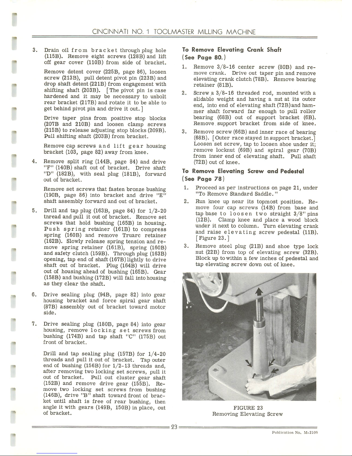
CINCINNATI
NO.
1
TOOLMASTER
MILLING
MACHINE
3.
Drain
oil
from
bracket
through
plug
hole
(115B).
Remove
eight
screws
(128B)
and
lift
off
gear
cover
(HOB)
from
side
of
bracket.
Remove
detent
cover
(225B,
page
86),
loosen
screw
(213B),
pull
detent
pivot
pin
(223B)
and
drop
shaft
detent
(22IB)
from
engagement
with
shifting shaft (203B).
[The
pivot piniscase
hardened
and
it
may
be
necessary
to
unbolt
rear
bracket
(217B)
and
rotateittobeable
to
get behind pivot pin and
drive
it out. ]
Drive
taper
pins
from
positive
stop
blocks
(207B
and
210B)
and
loosen
clamp
screws
(215B) to
release
adjusting
stop
blocks
(209B).
Pull
shifting
shaft
(203B)
from
bracket.
Remove
cap
screws
and
lift
gear
housing
bracket
(103,
page
82)
away
from
knee.
4.
Remove
split
ring
(144B,
page
84)
and
drive
"F"
(HOB)
shaft
outofbracket.
Drive
shaft
"D"
(182B), with
seal
plug
(181B),
forward
outofbracket.
Remove
set
screws
that
fasten
bronze
bushing
(190B,
page
86)
into
bracket
and
drive
"E"
shaft
assembly
forward
and
outofbracket.
5.
Drill
and
tap
plug
(163B,
page
84)
for
1/2-20
thread
and
pullitoutofbracket.
Remove
set
screws
that
hold
bushing
(165B) in
housing.
Push
spring
retainer
(16IB)
to
compress
spring
(160B)
and
remove
Truarc
retainer
(162B). Slowly
release
spring
tension
and
re
move
spring
retainer
(161B),
spring
(160B)
and
safety
clutch
(159B).
Through
plug
(163B)
opening,
tap
endofshaft
(167B)
lightlytodrive
shaft
outofbracket.
Plug
(164B)
will
drive
outofhousing
aheadofbushing
(165B).
Gear
(158B) and bushing (172B) will
fall
into housing
as
they
clear
the
shaft.
6.
Drive
sealing
plug
(94B,
page
82)
into
gear
housing
bracket
and
force
spiral
gear
shaft
(87B)
assembly
outofbracket
toward
motor
side.
7.
Drive
sealing
plug (180B,
page
84) into
gear
housing,
remove
locking
set
screws
from
bushing
(174B)
and
tap
shaft
"C"
(175B)
out
front
of
bracket.
Drill
and
tap
sealing
plug
(157B)
for
1/4-20
threads
and
pullitoutofbracket.
Tap
outer
endofbushing
(156B)
for
1/2-13
threads
and,
after
removing
two
locking
set
screws,
pull
it
outofbracket.
Pull
out
cluster
gear
shaft
(152B) and
remove
drive
gear
(155B). Re
move
two
locking
set
screws
from
bushing
(146B),
drive
"B"
shaft
toward
front
of
brac
ket
until
shaftisfree
of
rear
bushing,
then
angleitwith
gears
(149B, 150B) in
place,
out
of
bracket.
23:
To
Remove
Elevating
Crank
Shaft
(See
Page
80.)
1.
Remove
3/8-16
center
screw
(80B)
and
re
move
crank.
Drive
out
taper
pin
and
remove
elevating
crank
clutch
(78B).
Remove
bearing
retainer
(8IB).
2.
Screwa3/8-16
threaded
rod,
mounted
with
a
slidable
weight
and
havinganutatits
outer
end,
into
endofelevating
shaft
(72B)and
ham
mer
shaft
forward
far
enough
to
pull
roller
bearing
(68B)
out
of
support
bracket
(6B).
Remove
support
bracket
from
side
of
knee.
3.
Remove
screw
(66B)
and
inner
raceofbearing
(68B). [Outer
race
stayed in support bracket.]
Loosen
set
screw,
taptoloosen
shoe
under
it;
remove
locknut
(69B)
and
spiral
gear
(70B)
from
inner
endofelevating
shaft.
Pull
shaft
(72B)
outofknee.
To
Remove
Elevating
Screw
and
Pedestal
(See Page
78)
1.
Proceed
as
per
instructions
on
page
21,
under
"To
Remove
Standard
Saddle.
"
2.
Run
knee
up
near
its
topmost
position.
Re
move
four
cap
screws
(14B)
from
base
and
tap
base
to
loosen
two
straight
3/8"
pins
(12B).
Clamp
knee
and
placeawood
block
underitnexttocolumn.
Turn
elevating
crank
and
raise
elevating
screw
pedestal
(11B).
[Figure
23.]
3.
Remove
steel
plug
(2IB)
and
shoe
type
lock
nut
(22B)
from
top
of
elevating
screw
(32B).
Blockupto
withinafew
inchesofpedestal
and
tap
elevating
screw
down
outofknee.
FIGURE
23
Removing
Elevating
Screw
Publication
No.
M-2109
Page 25
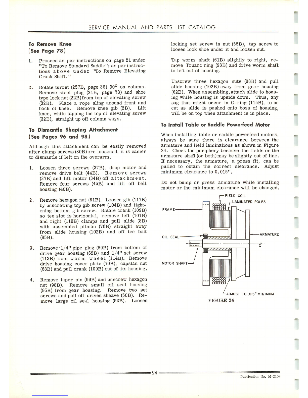
SERVICE
MANUAL
AND
PARTS
LIST
CATALOG
To
Remove
Knee
(See
Page
78)
1.
Proceed
as
per
instructions
on
page21under
"To
Remove
Standard
Saddle";
as
per
instruc
tions
above
under
"To
Remove
Elevating
Crank
Shaft."
2. Rotate
turret
(257B, page 36) 90° on column.
Remove
steel
plug
(2IB,
page
78)
and
shoe
type
lock
nut
(22B)from
top of
elevating
screw
(32B).
Placearope
sling
around
front
and
back
of
knee.
Remove
knee
gib
(2B).
Lift
knee,
while
tapping
the
topofelevating
screw
(32B),
straight
up off
column
ways.
To
Dismantle
Shaping
Attachment
(See Pages 96
and
98.)
Although
this
attachment
can
be
easily
removed
after
clamp
screws
(80B)are
loosened,itis
easier
to
dismantle
if
left
on
the
overarm.
1.
Loosen
three
screws
(37B),
drop
motor
and
remove
drive
belt
(44B).
Remove
screws
(37B)
and
lift
motor
(34B) off
attachment.
Remove
four
screws
(45B)
and
lift
off
belt
housing
(40B).
2. Remove hexagon nut (81B). Loosen gib (117B)
by
unscrewing
top gib
screw
(104B)
and
tight
ening bottom gib
screw.
Rotate
crank
(109B)
so
tee
slotishorizontal,
remove
left
(101B)
and
right
(118B)
clamps
and pull slide (8B)
with
assembled
pitman
(76B)
straight
away
from
slide
housing
(102B)
and
off
tee
bolt
(85B).
3.
Remove
1/4"
pipe
plug
(89B)
from
bottom
of
drive
gear
housing (62B) and
1/4"
set
screw
(113B)
from
worm
wheel
(114B).
Remove
drive
housing
cover
plate
(70B),
capstan
nut
(68B)
and
pull
crank
(109B)
outofits
housing.
4.
Remove
taper
pin
(99B)
and
unscrew
hexagon
nut
(98B).
Remove
small
oil
seal
housing
(95B)
from
gear
housing.
Remove
two
set
screws
and
pull
off
driven
sheave
(50B). Re
move
large
oil
seal
housing
(53B).
Loosen
locking
set
screw
in
nut
(55B),
tap
screw
to
loosen
lock
shoe
under
it
and
loosen
nut.
Tap
worm
shaft
(61B)
slightly
to
right,
re
move
Truarc
ring
(93B)
and
drive
worm
shaft
to
left
outofhousing.
Unscrew
three
hexagon
nuts
(88B)
and
pull
slide
housing
(102B)
away
from
gear
housing
(62B).
When
assembling,
attach
slidetohous
ing
while
housing
is
upside
down.
Thus,
any
sag
that
might
occur
in
O-ring
(115B), to be
cut
as
slide
is
pushed
onto
boss
of
housing,
willbeon
top
when
attachment
isinplace.
To
Install
Table
or
Saddle
Powerfeed
Motor
When
installing
table
or
saddle
powerfeed
motors,
always
be
sure
there
is
clearance
between
the
armature
and
field
laminations
as
showninFigure
24.
Check
the
periphery
because
the
fields
or
the
armature
shaft
(or
both)may
be
slightly
outofline.
If
necessary,
the
armature,
a
press
fit,
can
be
pulled
to
obtain
the
correct
clearance.
Adjust
minimum
clearance
to
0.015".
Do
not
bump
or
press
armature
while
installing
motor
or
the
minimum
clearance
will
be
changed.
FIELD
COIL
^-LAMINATED
POLES
FRAME
OIL
SEAL
MOTOR
SHAFT
=
24
ARMATURE
-ADJUSTTO.015"
MINIMUM
FIGURE
24
Publication
No.
M-2109
Page 26
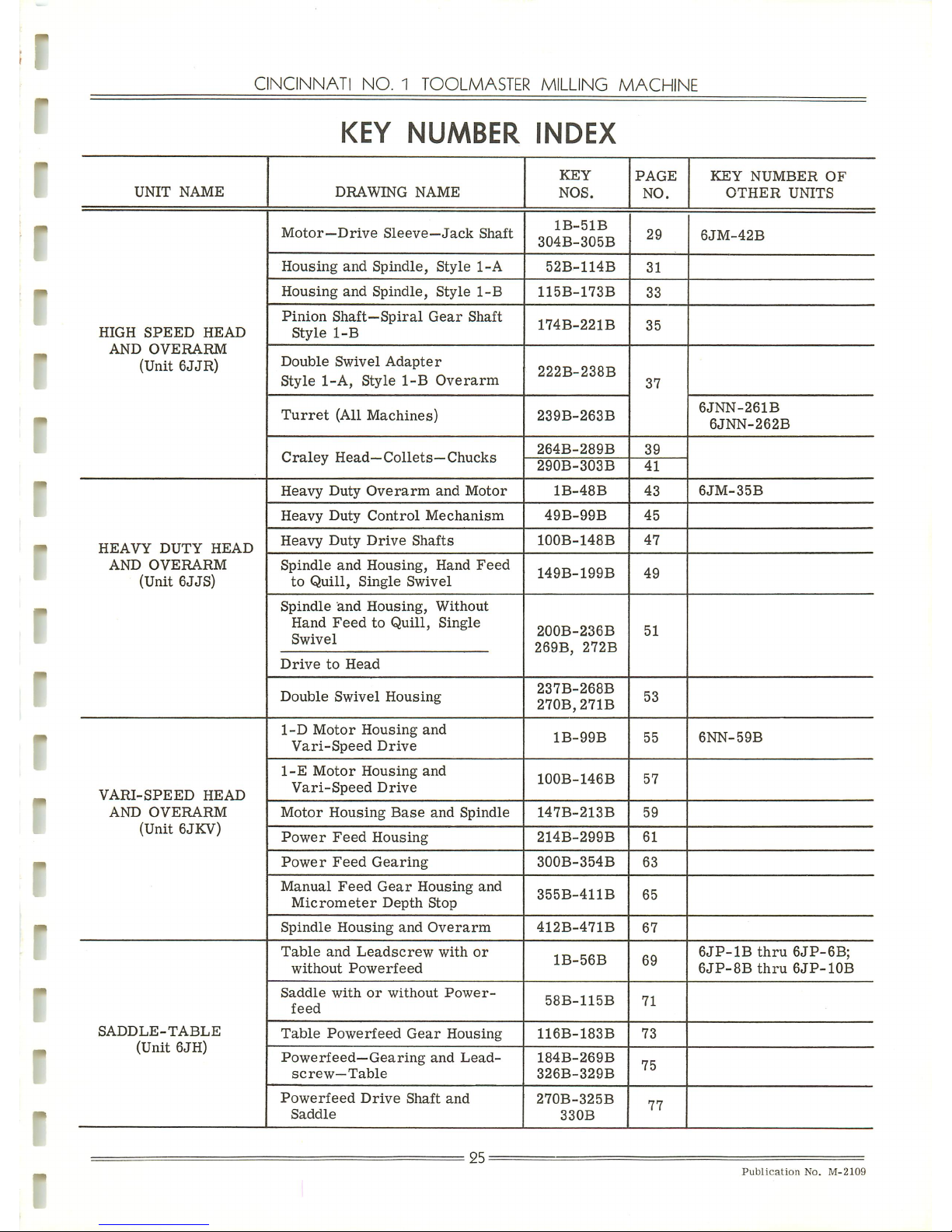
-
I
r
I
r
"
CINCINNATI
NO.
1
TOOLMASTER
MILLING
MACHINE
KEY
NUMBER
INDEX
UNIT
NAME
DRAWING
NAME
KEY
NOS.
PAGE
NO.
KEY
NUMBER
OF
OTHER
UNITS
Motor—Drive
Sleeve—Jack
Shaft
1B-51B
304B-305B
29
6JM-42B
Housing
and
Spindle,
Style
1-A
52B-114B
31
Housing
and
Spindle,
Style
1-B
115B-173B
33
HIGH
SPEED
HEAD
Pinion
Shaft-Spiral
Gear
Shaft
Style
1-B
174B-221B
35
AND
OVERARM
(Unit
6JJR)
Double
Swivel
Adapter
Style
1-A,
Style
1-B
Overarm
222B-238B
37
Turret
(All
Machines)
239B-263B
6JNN-261B
6JNN-262B
Craley
Head—Collets—Chucks
264B-289B
39
290B-303B
41
Heavy
Duty
Overarm
and
Motor
1B-48B
43
6JM-35B
Heavy
Duty
Control
Mechanism
49B-99B
45
HEAVY
DUTY
HEAD
Heavy
Duty
Drive
Shafts
100B-148B
47
AND
OVERARM
(Unit
6JJS)
Spindle
and
Housing,
Hand
Feed
to
Quill,
Single
Swivel
149B-199B
49
Spindle
and
Housing,
Without
Hand
FeedtoQuill,
Single
Swivel
Drive
to
Head
200B-236B
269B,
272B
51
Double
Swivel
Housing
237B-268B
270B,271B
53
1-D
Motor
Housing
and
Vari-Speed
Drive
1B-99B
55
6NN-59B
VARI-SPEED
HEAD
1-E
Motor
Housing
and
Vari-Speed
Drive
100B-146B
57
AND
OVERARM
(Unit
6JKV)
Motor
Housing
Base
and
Spindle
147B-213B
59
Power
Feed
Housing
214B-299B
61
Power
Feed
Gearing
300B-354B
63
Manual
Feed
Gear
Housing
and
Micrometer
Depth
Stop
355B-411B
65
Spindle
Housing
and
Overarm
412B-471B
67
Table
and
Leadscrew
with
or
without
Powerfeed
1B-56B
69
6JP-1B
thru
6JP-6B;
6JP-8Bthru
6JP-10B
Saddle
with
or
without
Power-
feed
58B-115B
71
SADDLE-TABLE
(Unit
6JH)
Table
Powerfeed
Gear
Housing
116B-183B
73
Powerfeed—Gearing
and
Lead-
screw—Table
184B-269B
326B-329B
75
Powerfeed
Drive
Shaft
and
Saddle
270B-325B
330B
77
25-
Publication
No.
M-2109
Page 27
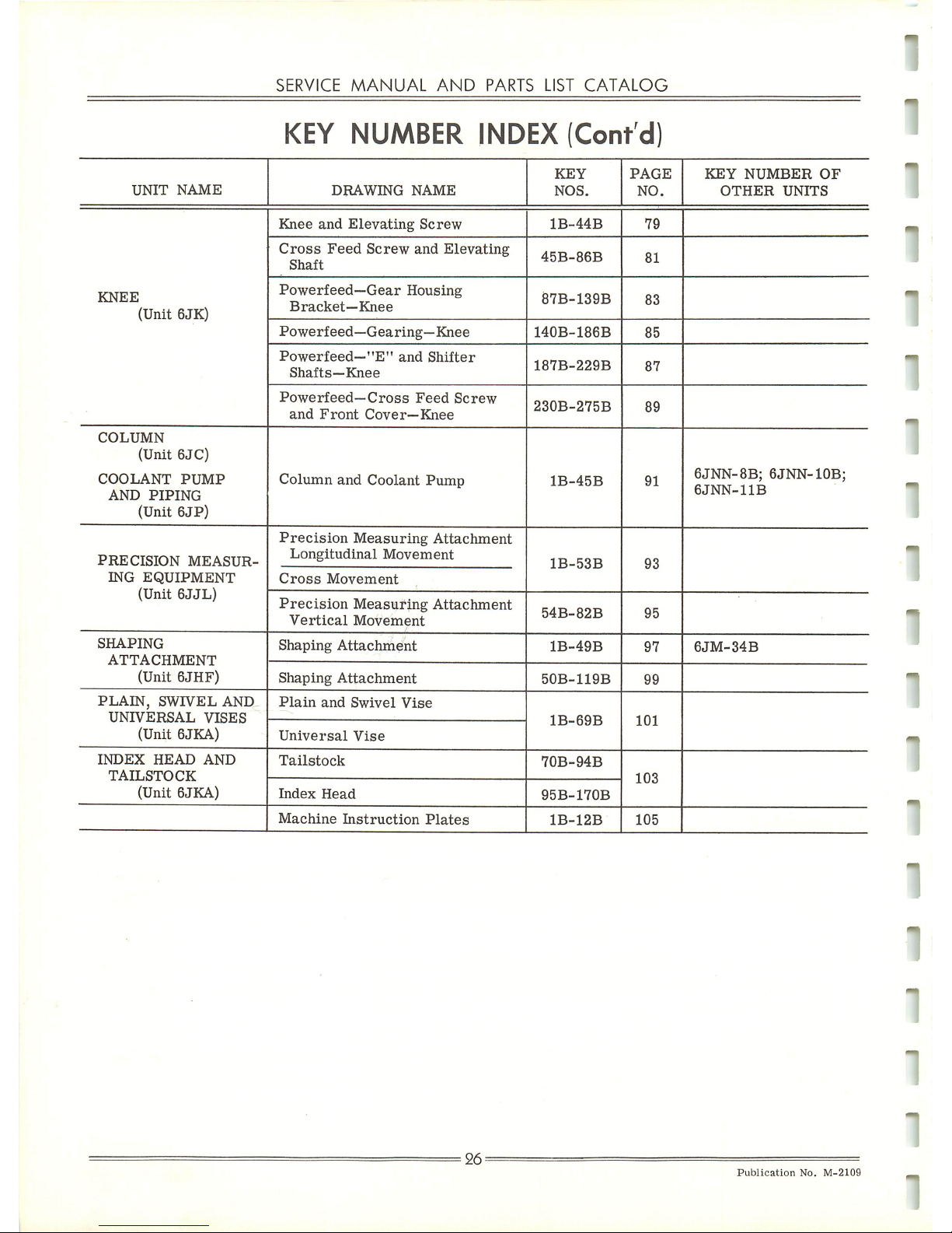
SERVICE
MANUAL
AND
PARTS
LIST
CATALOG
KEY NUMBER INDEX (Cont'd)
UNIT
NAME
DRAWING
NAME
KEY
NOS.
PAGE
NO.
KEY
NUMBER
OF
OTHER
UNITS
Knee
and
Elevating
Screw
1B-44B
79
Cross
Feed
Screw
and
Elevating
Shaft
45B-86B
81
KNEE
(Unit
6JK)
Powerfeed—Gear
Housing
Bracket—Knee
87B-139B
83
Powerfeed—Gearing—Knee
140B-186B
85
Powerfeed-"E"
and
Shifter
Shafts—Knee
187B-229B
87
Powerfeed—Cross
Feed
Screw
and
Front
Cover—Knee
230B-275B
89
COLUMN
(Unit
6JC)
COOLANT
PUMP
AND
PIPING
(Unit
6JP)
Column
and
Coolant
Pump
1B-45B
91
6JNN-8B;
6JNN-10B;
6JNN-11B
PRECISION
MEASUR
ING
EQUIPMENT
(Unit
6JJL)
Precision
Measuring
Attachment
Longitudinal
Movement
Cross
Movement
1B-53B
93
Precision
Measuring
Attachment
Vertical
Movement
54B-82B
95
SHAPING
ATTACHMENT
Shaping
Attachment
1B-49B
97
6JM-34B
(Unit
6JHF)
Shaping
Attachment
50B-119B
99
PLAIN,
SWIVEL
AND
UNIVERSAL
VISES
Plain
and
Swivel
Vise
1B-69B
101
(Unit 6JKA)
Universal
Vise
INDEX
HEAD
AND
TAILSTOCK
Tailstock
70B-94B
103
(Unit 6JKA)
Index
Head
95B-170B
Machine
Instruction
Plates
1B-12B
105
26-
Publication
No.
M-2109
Page 28
CINCINNATI
NO.
1
TOOLMASTER
MILLING
MACHINE
HOW
TO
ORDER
REPAIR
PARTS
You will receive quicker
and
better
service when ordering repair
partsifyou
will adhere to
the
following
instructions
when
ordering
such
replacements.
These
four
requirements
are
essential:
1.
State
amount
wanted.
2.
Give catalog key number, part number and name of part. If ordering parts by part num
ber, please advise where the number was obtained. (See paragraph A, below.)
3.
Give
complete
serial
numberofmachine.
(This
number
will be
found
stamped at top of
column front face between dovetail ways. See Figure 4B)
4. Specify how and where to ship. (See paragraph B, below.)
Paragraph
A
When ordering parts by number, kindly
advise
howthe number was obtained, namely:
Number
stamped
on
part.
Prior
Invoice.
Parts List Catalog. (Give identification and publication numbers on front cover.)
Paragraph
B
Do not say, "Ship quickest way." Be definite and state agency desired, that
is—Air
Mail,
Parcel
Post (Special Delivery),
Parcel
Post (Regular),
Express,
MotorFreight, Rail Freight,
etc.
Specify each individual piece that is required in the order. If only certain parts of a unit
are required, never use the word "complete"; it always raises a question as to how much
of a
unittosupply.
However,insome
cases,
due
to the nature of the part, it
willbenecessary,
and
less
costly
to you, for us to supply additional related pieces, especially if
part
wanted is obsolete.
27
Publication
No.
M-2109
Page 29
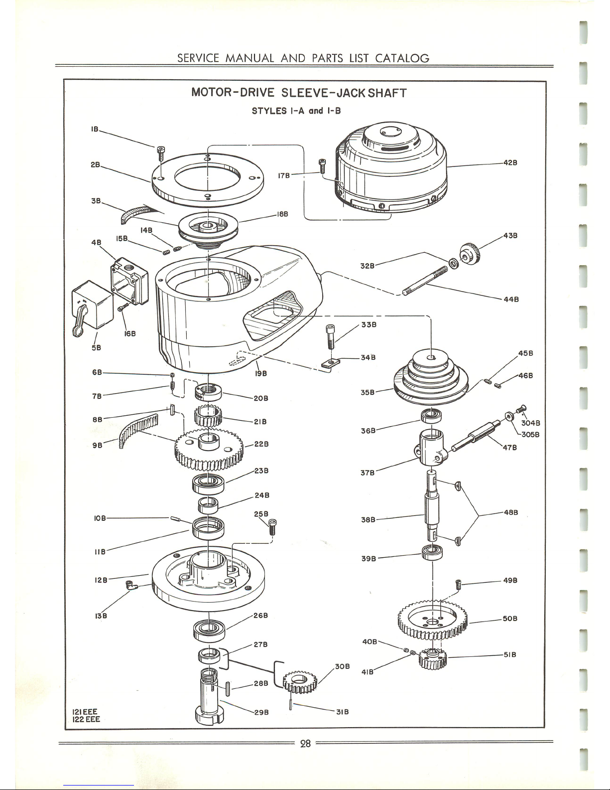
121EEE
122
EEE
SERVICE
MANUAL
AND
PARTS
LIST
CATALOG
MOTOR-DRIVE
SLEEVE-JACK
SHAFT
STYLES
1-A
and
1-B
28
Page 30
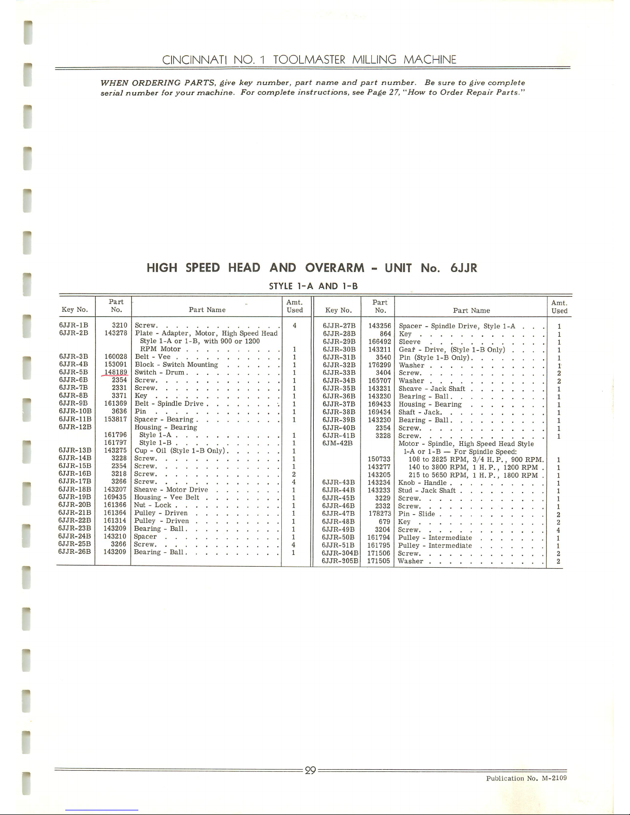
CINCINNATI
NO.
1
TOOLMASTER
MILLING
MACHINE
WHEN
ORDERING
PARTS,
give
key
number,
part
name
and
part
number.
Be
suretogive
complete
serial
number
for
your
machine.
For
complete
instructions,
see
Page
27,
"HowtoOrder
Repair
Parts."
HIGH
SPEED
HEAD
AND
OVERARM
-
UNIT
No.
6JJR
STYLE
1-A
AND
1-B
Key
No.
Part
No.
Part
Name
Amt.
Used
Key
No.
Part
No.
Part
Name
Amt.
Used
6JJR-1B
3210
143278
160028
153091
148189
2354
2331
3371
161369
3636
153817
161796
161797
143275
3228
2354
3218
3266
143207
169435
161366
161364
161314
143209
143210
3266
143209
4
4
1
6JJR-27B
6JJR-28B
6JJR-29B
6JJR-30B
6JJR-31B
6JJR-32B
6JJR-33B
6JJR-34B
6JJR-35B
6JJR-36B
6JJR-37B
6JJR-38B
6JJR-39B
6JJR-40B
6JJR-41B
6JM-42B
6JJR-43B
6JJR-44B
6JJR-45B
6JJR-46B
6JJR-47B
6JJR-48B
6JJR-49B
6JJR-50B
6JJR-51B
6JJR-304B
6JJR-305B
143256
864
166492
143211
3540
176299
3404
165707
143231
143230
169433
169434
143230
2354
3228
150733
143277
143205
143234
143233
3229
2332
178273
679
3204
161794
161795
171506
171505
Spacer-Spindle
Drive,
Style
1-A
. . .
Key
6JJR-2B
Plate-Adapter,
Motor,
High
Speed
Head
Style
1-Aor1-B,
with
900or1200
RPM
Motor
Sleeve
Geaf-Drive,
(Style
1-B
Only) . . . .
Pin
(Style
1-B
Only)
6JJR-3B
Belt-Vee
6JJR-4B
6JJR-5B
6JJR-6B
6JJR-7B
6JJR-8B
Key
6JJR-9B
6JJR-10B
Belt-Spindle
Drive
•.
Pin
Shaft-Jack.
6JJR-11B
Housing-Bearing
Style
1-A
6JJR-12B
Style
1-B
Motor-Spindle,
High
Speed
Head
Style
1-Aor1-B—For
Spindle
Speed:
108 to 2825 RPM,
3/4H.P.,
900 RPM.
140 to 3800
RPM,
1 H. P. , 1200
RPM
.
215 to
5650
RPM,
1 H.P.,
1800
RPM
.
6JJR-13B
6JJR-14B
Cup - Oil
(Style
1-B
Only)
Screw
6JJR-15B
6JJR-16B
6JJR-17B
6JJR-18B
6JJR-19B
Sheave-Motor
Drive
Nut-Lock
Stud-Jack
Shaft
6JJR-20B
6JJR-21B
6JJR-22B
Bearing-Ball
Pin-Slide
Key
2
2
6JJR-23B
4
6JJR-24B
1
1
2
6JJR-25B
6JJR-26B
Bearing-Ball
2
•29--
Publication
No.
M-2109
Page 31

121
EEE
SERVICE
MANUAL
AND
PARTS LIST
CATALOG
HOUSING
AND
SPINDLE
STYLE
1-A
78
B
30
86B
Page 32

Key
No.
6JJR-52B
6JJR-53B
6JJR-54B
6JJR-55B
6JJR-56B
6JJR-57B
6JJR-58B
6JJR-59B
6JJR-60B
6JJR-61B
6JJR-62B
6JJR-63B
6JJR-64B
6JJR-65B
6JJR-66B
6JJR-67B
6JJR-68B
6JJR-69B
6JJR-70B
6JJR-71B
6JJR-72B
6JJR-73B
6JJR-74B
6JJR-75B
6JJR-76B
6JJR-77B
6JJR-78B
6JJR-79B
6JJR-80B
6JJR-81B
CINCINNATI
NO.
1
TOOLMASTER
MILLING
MACHINE
WHEN
ORDERING
PARTS,
give
key
number,
part
name
and
part
number.
Be
suretogive
complete
serial
number
for
your
machine.
For
complete
instructions,
see
Page
27,
"HowtoOrder
Repair
Parts."
HIGH
SPEED
HEAD
AND
OVERARM - UNIT No.
6JJR
(Continued)
STYLE
1-A
Part
No.
143217
153081
143216
153080
166496
166495
166494
3396
30060
100239
165708
165709
165711
2355
165710
78907
141
143219
143220
153080
143213
3246
3810
3809
153804
153808
153806
143218
3270
152340
143249
143247
2255
Part
Name
Stop-Adjusting
Depth
English
Metric
Screw-Lead,
Depth
Stop
English
Metric
Pin
Sleeve-Mounting.
Shaft-Lock
Screw
Ball-Steel
Spring
Shoe-Clamp
Shoe-Clamp
Spacer-Clamp
....
Screw
Screw-Clamp
Lever
Pin-Taper
Stud-Locking,
Depth
Stop.
Wheel-Thumb,
Depth
Stop
English
Metric
Key-Stop
Screw
Nut-Lock
Washer-Lock
Cap-Bearing
Bearing-Ball
Spacer-Quill
Nut-Locking,
Depth
Stop
.
Pin
Shaft-Pinion
Housing-Spring
....
Spring-Torsion
....
Screw-Thumb
....
Amt.
Used
Key
No.
6JJR-82B
6JJR-83B
6JJR-84B
6JJR-85B
6JJR-86B
6JJR-87B
6JJR-88B
6JJR-89B
6JJR-90B
6JJR-91B
6JJR-92B
6JJR-93B
6JJR-94B
6JJR-95B
6JJR-96B
6JJR-97B
6JJR-98B
6JJR-99B
6JJR-100B
6JJR-101B
6JJR-102B
6JJR-103B
6JJR-104B
6JJR-105B
6JJR-106B
6JJR-107B
6JJR-108B
6JJR-109B
6JJR-110B
6JJR-111B
6JJR-112B
6JJR-113B
6JJR-114B
Part
No.
159959
153079
143245
143252
3942
143250
3198
4356
4341
228994
3228
166493
2339
4357
3479
3311
3442
224865
166499
143251
140
170785
168055
153807
153805
153802
153807
152362
153803
2321
143235
1383
166491
170511
Part
Name
Dial-Spring
Cover
English
Metric
Hub-Handle
Pin-Spring
Spring
Retainer-Hub
Screw
Knob-Lever,
Handfeed
Plate-Name
Cup -
Oil,
Style
1-A.
. . .
Screw
Sleeve-Spindle
Quill
Feed
Screw
Washer,
Knob-Lever
. . .
Nut
Bolt-"T"
Washer
Cup-Oil
Housing - Spindle (Style 1-A) .
Screw-Spring
Retainer
Pin-Taper
Lever-Handfeed
Knob-Lever,
Handfeed
. .
Bearing-Ball,
Lower
. . .
Spacer-Outer,
Lower
Bearings
Spacer-Inner,
Lower
Bearings
Bearing-Ball,
Lower
. . .
Seal-Bearing
Nut-Lock
Screw
Gear-Spiral
Pin
Spindle-Drive
Nut-Spindle
Amt.
Used
31
Publication
No.
M-2109
Page 33

122
EEE
SERVICE
MANUAL
AND
PARTS LIST
CATALOG
HOUSING
AND
SPINDLE
STYLE
1-B
I73B
WRENCH
ALSO
USED
FOR
SPINDLE
NUT
ON
STYLE
1-A
HOUSING
=•
32
Page 34

Key
No.
6JJR-115B
6JJR-116B
6JJR-117B
6JJR-118B
6JJR-11SB
6JJR-120B
6JJR-121B
6JJR-122B
6JJR-123B
6JJR-124B
6JJR-125B
6JJR-126B
6JJR-127B
6JJR-128B
6JJR-129B
6JJR-130B
6JJR-131B
6JJR-132B
6JJR-133B
6JJR-134B
6JJR-135B
6JJR-136B
6JJR-137B
6JJR-138B
6JJR-139B
6JJR-140B
6JJR-141B
6JJR-142B
6JJR-143B
6JJR-144B
6JJR-145B
6JJR-146B
6JJR-147B
CINCINNATI
NO.
1
TOOLMASTER
MILLING
MACHINE
WHEN
ORDERING
PARTS,
give
key
number,
part
name
and
part
number.
Be
suretogive
complete
serial
number
for
your
machine.
For
complete
instructions,
see
Page
27,
"HowtoOrder
Repair
Parts."
HIGH
SPEED
HEAD
AND
OVERARM
STYLE
1-B
UNIT
No.
6JJR
(Continued)
Part
No.
143268
2291
153819
143269
143266
143498
255822
143281
143271
76645
3396
170511
1383
2321
143235
152362
153803
166491
3311
3442
3379
3232
2332
3230
2332
2341
2316
101732
30060
166493
2339
3810
3809
Part
Name
Gear-Driven
Pin
Sleeve-Thrust
. . . .
Shaft-Worm
Bushing-Sleeve
. . . .
Washer
Plug
Gasket
Plate-Cover
Plug
Screw
Nut-Spindle
Pin
Screw
Gear-Spiral
Washer
Nut-Lock
Spindle-Drive
. . . .
Bolt-Tee
Washer
Nut
Screw
Screw
Screw
Screw
Screw
Screw
Spring-Compression
.
Ball-Steel
Sleeve-Spindle
Quill
Feed
Screw
Nut-Lock
Washer-Lock
Amt.
Used
Key
No.
6JJR-148B
6JJR-149B
6JJR-150B
6JJR-151B
6JJR-152B
6JJR-153B
6JJR-154B
6JJR-155B
6JJR-156B
6JJR-157B
6JJR-158B
6JJR-159B
6JJR-160B
6JJR-161B
6JJR-162B
6JJR-163B
6JJR-164B
6JJR-165B
6JJR-166B
6JJR-167B
6JJR-168B
6JJR-169B
6JJR-170B
6JJR-171B
6JJR-172B
6JJR-173B
Part
No.
153804
153808
153806
166497
166495
30060
143213
100239
153805
153802
153807
143217
153081
143216
153080
3228
3229
2333
143218
3270
143219
143220
153082
166496
166494
3396
2355
3246
143538
Part
Name
Cap-Bearing
Bearing-Ball
Spacer-Quill
Housing-Spindle,
Style
1-B
.
Sleeve-Mounting
Ball-Steel
Key-Stop
Spring
Spacer-Outer,
Lower
Bearings
Spacer-Inner,
Lower
Bearings
Bearing-Ball,
Lower
.
Stop-Adjusting
Depth
English
Metric
Screw-Lead,
Depth
Stop
English
Metric
Screw
Screw
Screw
Nut-Locking,
Depth
Stop
.
Pin
Stud-Locking,
Depth
Stop.
Wheel-Thumb,
Depth
Stop
English
Metric
Pin
Shaft-Lock
Screw
Screw
Screw
Wrench
Amt.
Used
33^
Publication
No.
M-2109
Page 35

122
EEE
SERVICE
MANUAL
AND
PARTS
LIST
CATALOG
PINION
SHAFT-SPIRAL
GEAR
SHAFT
STYLE
1-B
.208B
209B
2I2B
34
Page 36

"
CINCINNATI
NO.
1
TOOLMASTER
MILLING
MACHINE
WHEN
ORDERING
PARTS,
give
key
number,
part
name
and
part
number.
Be
suretogive
complete
serial
number
for
your
machine.
For
complete
instructions,
see
Page
27,
"HowtoOrder
Repair
Parts."
Key
No.
6JJR-174B
6JJR-175B
6JJR-176B
6JJR-177B
6JJR-178B
6JJR-179B
6JJR-180B
6JJR-181B
6JJR-182B
6JJR-183B
6JJR-184B
6JJR-185B
6JJR-186B
6JJR-187B
6JJR-188B
6JJR-189B
6JJR-190B
6JJR-191B
6JJR-192B
6JJR-193B
6JJR-194B
6JJR-195B
6JJR-196B
/
HIGH
SPEED
HEAD
AND OVERARM -
UNIT
No. 6JJR (Continued)
STYLE
1-A
AND
1-B
Part
No.
3530
143242
700449
143240
143241
2333
143243
143239
143238
152342
3280
143249
3198
143247
2255
159959
153079
143245
143252
3942
143251
143250
140
170785
Part
Name
Plug
Knob-Hand
Clutch
. .
Seal-Oil
Pin-Adjusting
. .
Collar-Clutch
Adjusting
Screw
Shoe
Clutch-Friction
Male
.
Gear-Spiral
....
Shaft-Pinion
....
Key
Housing-Spring
.
Screw
Spring-Torsion
. .
Screw-Thumb
Dial-Spring
Cover
English
Metric
Hub-Handle
....
Pin-Spring
....
Spring
Screw-Spring
Retainer
Retainer-Hub.
. . .
Pin-Taper
Handle-Handfeed
Amt.
Used
Key
No.
6JJR6JJR6JJR6JJR6JJR6JJR-
6JJR6JJR6JJR-
6JJR6JJR6JJR-
6JJR-
6JJR6JJR-
6JJR-
6JJR6JJR-
6JJR-
6JJR-
6JJR6JJR6JJR-
6JJR-
6JJR-
197B
198B
199B
200B
201B
202B
203B
204B
205B
206B
207B
208B
209B
210B
211B
212B
213B
214B
215B
216B
217B
218B
219B
220B
221B
Part
No.
155655
168055
4357
4356
4341
165708
165709
165711
165710
141
78907
143260
143259
143258
143266
143265
143266
143264
2341
143267
119764
2341
143263
143266
143265
Part
Name
Shaft - Shifter . . .
Knob-Handfeed
.
Washer
Knob-Handfeed
. .
Plate-Name
.
Shoe-Clamp
.
Shoe-Clamp
. . .
Spacer-Shoe
Clamp,
Screw-Clamp.
. .
Pin-Taper.
. .
Lever
Sleeve-Thrust
. .
Shaft-Spiral
Gear
.
Gear-Shifter
. . .
Bushing-Sleeve
.
Plug-Expansion
.
Bushing-Sleeve
.
Shaft-Transmission
Screw
Gear-Transmission
Ring-Spring
Wire
.
Screw
Gear-Spiral
. . .
Bushing-Sleeve
.
Plug-Expansion
.
Amt.
Used
35
=
Publication
No.
M-2109
-
Page 37

I5EEE
76
EEE
TURRET
ALL
MACHINES
28
EEE
SERVICE
MANUAL
AND
PARTS
LIST
CATALOG
222B
223B
224
B
DOUBLE
SWIVEL
ADAPTER
229B
23IB
230B
STYLE
1-A,
STYLE
1-B
OVERARM
235B
242
B
251B
254B
252B
253B
246B
245B\247B
244B
243B
36
249
B
232B
Page 38

•
•
•
Key
No.
6JJR-222B
6JJR-223B
6JJR-224B
6JJR-225B
6JJR-226B
6JJR-227B
6JJR-228B
6JJR-229B
6JJR-230B
CINCINNATI
NO.
1 TOOLMASTER MILLING
MACHINE
WHEN
ORDERING
PARTS,
give
key
number,
part
name
and
part
number.
Be
suretogive
complete
serial
number
for
your
machine.
For
complete
instructions,
see
Page
27,
"HowtoOrder
Repair
Parts."
HIGH
SPEED
HEAD
AND OVERARM -
UNIT
No. 6JJR (Continued)
STYLE
1-A
AND
1-B
Part
No.
153085
153084
153085
3479
3442
3311
143235
2321
3233
Part
Name
Bushing
....
Shaft-Spiral
Gear
Bushing
....
Nut
Washer
....
Bolt-Tee
. . .
Gear-Spiral.
. .
Screw
Screw
Amt.
Used
Key
No.
6JJR-231B
6JJR-232B
6JJR-233B
6JJR-234B
6JJR-235B
6JJR-236B
6JJR-237B
6JJR-238B
TURRET
Part
No.
143279
1383
161756
2248
105147
161755
148623
148624
Part
Name
Adapter-Overarm
.
Pin
Overarm-Style
1-Aor1-B
Screw-Set
Screw
Bushing
Shaft-Spiral
Gear
. . .
Bushing
Amt.
Used
Key
No.
Part
No.
Part
Name
Amt.
Used
Key
No.
Part
No.
Part
Name
Amt.
Used
6JJR-239B
150700
151458
151461
151460
2343
2355
2343
2316
151459
148717
151457
152376
3605
Handle-#6
Williams
Crank
Shaft-Pinion
6JJR-251B
6JJR-252B
6JJR-253B
6JJR-254B
6JJR-255B
6JJR-256B
6JJR-257B
6JJR-258B
6JJR-259B
6JJR-260B
6JNN-261B
6JNN-262B
6JJR-263B
3480
161746
161754
153491
3480
1040
151451
3228
2332
1387
150703
3199
143424
Nut
2
6JJR-240B
6JJR-241B
2
2
6JJR-242B
6JJR-243B
Nut
.
1
4
6JJR-244B
6JJR-245B
Turret
(Altered
per
Drawing
143447 if
4
6JJR-246B
6JJR-247B
6JJR-248B
Roll-Pin
1
1
6JJR-249B
Bushing-Connector
With
Shaping
Attachment
Without
Shaping
Attachment
Pin
2
1
2
6JJR-250B
Bolt-Tee
21-
Publication
No.
M-2109
Page 39

SERVICE
MANUAL
AND
PARTS
LIST
CATALOG
"
Page 40

'
m
Key
No.
6JJR-264B
6JJR-265B
6JJR-266B
6JJR-267B
6JJR-268B
6JJR-269B
6JJR-270B
6JJR-271B
6JJR-272B
6JJR-273B
6JJR-274B
6JJR-275B
6JJR-276B
6JJR-277B
6JJR-278B
6JJR-279B
6JJR-280B
6JJR-281B
6JJR-282B
6JJR-283B
CINCINNATI
NO.
1
TOOLMASTER
MILLING
MACHINE
WHEN
ORDERING
PARTS,
give
key
number,
part
name
and
part
number.
Be
suretogive
complete
serial
number
for
your
machine.
For
complete
instructions,
see
Page
27,
"HowtoOrder
Repair
Parts."
HIGH
SPEED
HEAD
AND
OVERARM-UNIT
No. 6JJR (Continued)
STYLE
1-A
AND
1-B
Part
No.
153459
170511
157751
153099
153450
153451
153452
153453
153454
153455
153456
153098
153457
153458
153460
170511
157750
153462
153463
153464
153465
153466
153467
153468
153469
153470
153471
153472
153097
153461
2354
3228
152344
152343
152345
Part
Name
Adapter-No.3Craley
Head
Nut-Spindle
Head-No.3Craley
Offset
Boring
. . .
Bar-Boring
(No. 2
Bar
for
No. 3
Craley
Head)
Bar-Boring
(No. 3
Bar
for
No. 3
Craley
Head)
Bar-Boring
(No. 4
Bar
for No. 3
Craley
Head)
. . . .
Bar-Boring
(No. 5
Bar
for
No. 3
Craley
Head)
Bar-Boring,
Two
Lip
(For
No. 3
Craley
Head)
(A-l)-1/8"
Across
Lips
- Min.
Bore
.
(A-2) -
3/16"
Across
Lips
- Min.
Bore
(A-3)-1/4"
Across
Lips-Min.
Bore
.
(A-4) -
5/16"
Across
Lips
- Min.
Bore
(A-5)-3/8"
Across
Lips-Min.
Bore
.
(A-6) -
1/2"
Across
Lips
- Min.
Bore
.
(A-7) -
5/8"
Across
Lips
- Min.
Bore
.
Adapter-No.0Craley
Head
Nut-Spindle
Head
- No. 0
Craley
Offset
Boring
. . .
Bar-Boring
(No. 3
Bar
for
No. 0
Craley
Head)
Bar-Boring
(No. 4
Bar
for
No. 0
Craley
Head)
Bar-Boring
(No. 1
Bar
for
No. 0
Craley
Head)
Bar-Boring
(No. 5
Bar
for
No. 0
Craley
Head)
Bar-Boring,
Two
Lip
(For
No. 0
Craley
Head)
(A-l)-1/8"
Across
Lips-Min.
Bore
.
(A-2) -
3/16"
Across
Lips
- Min.
Bore
(A-3) -
1/4"
Across
Lips
- Min.
Bore
.
(A-4) -
5/16"
Across
Lips
- Min.
Bore
(A-5)-3/8"
Across
Lips-Min.
Bore
.
(A-6)-1/2"
Across
Lips-Min.
Bore
.
(A-7) -
5/8"
Across
Lips
- Min.
Bore
.
Unit-Craley
No. 3
Offset
Boring
Head
No. 0
Offset
Boring
Head
Screw
Screw
Adapter-Shell
End
Mill
1/2"
Diameter
Hole
Shell
End Mill . .
3/4"
Diameter
Hole
Shell
End
Mill
. .
1"
Diameter
Hole
Shell
End
Mill
. . .
Amt.
Part
Used
Key
No.
No.
1
6JJR
•284B
1
152351
1
152350
152349
1
6JJR
285B
4167
1
4168
4169
1
6JJR
-286B
152346
1
152347
152348
6JJR
•287B
1
152352
1
152353
1
152354
1
152355
1
6JJR-
288B
2301
1
6JJR
•289B
1
156218
1
156219
1
156220
1
156221
152107
1
156222
156223
1
132108
157031
1
157032
156224
1
157033
157026
157034
1
157027
1
157028
1
157035
1
157036
1
157029
1
157030
1
158150
158151
1
158152
1
158153
1
1
1
1
1
Part
Name
Collar-Arbor
1/2"
Diameter
Hole
Shell
End
Mill
3/4"
Diameter
Hole
Shell
End
Mill
1"
Diameter
Hole
Shell
End
Mill
.
Screw-Arbor
1/2"
Diameter
Hole
Shell
End
Mill
3/4"
Diameter
Hole
Shell
End
Mill
1"
Diameter
Hole
Shell
End
Mill
.
Pin-Driving
1/2"
Diameter
Hole
Shell
End
Mill
3/4"
Diameter
Hole
Shell
End
Mill
1"
Diameter
Hole
Shell
End
Mill
.
Adapter-End
Mill
3/8"
End
Mill
1/2"
End
Mill
5/8"
End
Mill
3/4"
End
Mill
Screw
Collet
3mmHole
4mmHole
5mmHole
6mmHole
7mmHole
8mmHole
10mmHole
13mmHole
14mmHole
15mmHole
16mmHole
18mmHole
20mmHole
22mmHole
24mmHole
25mmHole
26mmHole
28mmHole
30mmHole
32mmHole
#3
Morse
Taper
Hole
("C"
Series).
#2
Morse
Taper
Hole
("C"
Series).
#7 B and S
Taper
Hole
("C"
Series)
#5 B and S
Taper
Hole
("C"
Series)
*
Part
No. 153097 - Unit
consists
of key
numbers
264B
through
270B, 271B (A-5) and
wrenches.
**
Part
No. 153461 - Unit
consists
of key
numbers
272B
through
278B, 279B (A-5) and
wrenches.
Amt.
Used
39^
Publication
No.
M-2109
Page 41

264B
265
B
26
6B
SERVICE
MANUAL
AND
PARTS
LIST
CATALOG
CRALEY
HEAD-COLLETS-CHUCKS
272B
<
27
3B
274
B
2jsj
m
L
I 1 1
a
i
r—i
E
267B
268B
269B
270B
27IB
275B
276B
277B 278B 279B / 295B
28IB-
282B
283B
284B
285B
37EEE
45EEE
286B
287B
288B
299B
300B
289B
292B
/rtl
290B
^-^.
1
m^z™
Itr-294B
30IB
40
Page 42

'
•
"
Key
No.
6JJR-290B
6JJR-291B
6JJR-292B
6JJR-293B
6JJR-294B
6JJR-295B
6JJR-296B
CINCINNATI
NO.
1
TOOLMASTER
MILLING
MACHINE
WHEN
ORDERING
PARTS,
give
key
number,
part
name
and
part
number.
Be
suretogive
complete
serial
number
for
your
machine.
For
complete
instructions,
see
Page
27,
"HowtoOrder
Repair
Parts."
HIGH
SPEED
HEAD
AND
OVERARM-UNIT
No. 6JJR (Concluded)
STYLE
1-A
AND
1-B
Part
No.
864
864
814
152365
152367
3647
152357
152356
152358
152366
152368
152369
152364
1341
3693
177525
128930
161837-1
128931
161837-2
128932
161837-3
128933
161837-4
128934
161837-5
128935
161837-6
128936
153849
161841-1
153848
161841-2
153847
161841-3
161841-4
128937
128938
128939
128940
Part
Name
Key
3/4"
Stub
Arbor
7/8"
Stub
Arbor
1"
Stub
Arbor
Collar-Arbor
Spacing
1/2"
Wide
3/4"
Stub
Arbor
7/8"
Stub
Arbor.
1"
Stub
Arbor
Arbor-Stub
3/4"
Stub
Arbor
7/8"
Stub
Arbor
1"
Stub
Arbor
Collar-Arbor
Spacing
1/4"
Wide
3/4"
Stub
Arbor
7/8"
Stub
Arbor
1"
Stub
Arbor
Nut-Arbor
3/4"
Stub
Arbor
7/8"
Stub
Arbor
1"
Stub
Arbor
Adapter-Small
Collet,
"A"
Series
Collet
"A"
Series
1/8"
Hole
5/32"
Hole
3/16"
Hole
7/32"
Hole
1/4"
Hole
9/32"
Hole
5/16"
Hole
11/32"
Hole
3/8"
Hole
13/32"
Hole
7/16"
Hole
15/32"
Hole
1/2"
Hole
"C"
Series
3/8"
Hole
13/32"
Hole
7/16"
Hole
15/32"
Hole
1/2"
Hole
17/32"
Hole
9/16"
Hole
5/8"
Hole
3/4"
Hole
7/8"
Hole
'
1"
Hole
Amt.
Used
Key
No.
6JJR-297B
6JJR-299B
6JJR-300B
6JJR-301B
6JJR-302B
6JJR-303B
Part
No.
177526
152374
101759
152373
158151
158150
603023-1
603023-2
603023-4
603023-5
603023-7
603023-8
603023-11
603023-12
603023-15
603023-16
603023-19
603023-20
Part
Name
Nut-Small
Collet
Adapter,
"A"
Series
Block
- 3
Adapter
Wrench-Spanner
Block
- 4
Adapter
Collet-With
Jacobs
Chuck
#2
Morse
Taper
#3
Morse
Taper
Jacobs
Chuck
Chuck-Drill0"-
1/4"
#2
Morse
Taper
Chuck-Drill
0" -
1/4"
#3
Morse
Taper
Chuck-Drill0"-
3/8"
#2
Morse
Taper
Chuck-Drill0"-
3/8"
#3
Morse
Taper
Chuck-Drill0"-
1/2"
#2
Morse
Taper
Chuck-Drill
0" -
1/2"
#3
Morse
Taper
Chuck-Drill
3/32"-5/8"
#2
Morse
Taper
Chuck-Drill
3/32"-5/8"
#3
Morse
Taper
Chuck-Drill
3/32"-3/4"
#2
Morse
Taper
Chuck-Drill
3/32"-3/4"
#3
Morse
Taper
Chuck-Drill
3/8"
- 1"
#2
Morse
Taper
Chuck-Drill
3/8"
- 1"
#3
Morse
Taper
Amt.
Used
"A"
Series
collets
require
use of
small
collet
adapter
- Key No. 6JJR-295B; "C"
Series
collets
fit
directly
into spindle.
41
Publication
No.
M-2109
Page 43

TURRET
117
EEE
I63EEE
SERVICE
MANUAL
AND
PARTS
LIST
CATALOG
HEAVY
DUTY
OVERARM
AND
MOTOR
STYLE
IC
42
p
Page 44

CINCINNATI
NO.
1
TOOLMASTER
MILLING
MACHINE
WHEN
ORDERING
PARTS,
give
key
number,
part
name
and
part
number.
Be
suretogive
complete
serial
number
for
your
machine.
For
complete
instructions,
see
Page
27,
"HowtoOrder
Repair
Parts."
HEAVY
DUTY
HEAD
AND
OVERARM
-
UNIT
No.
6JJS
Key
No.
Part
No.
Part
Name
Amt.
Used
Key
No.
Part
No.
Part
Name
Amt.
Used
6JJS-1B
3521
3251
3987
167039
143317
2209
23173
1664
3266
143301
3266
105147
216607
167876
143295
3266
148624
243749
168165
243749
148624
97264
227570
93235
2343
2
2
1
1
1
4
2
2
12
1
2
2
6JJS-26B
6JJS-27B
6JJS-28B
6JJS-29B
6JJS-30B
6JJS-31B
6JJS-32B
6JJS-33B
6JJS-34B
6JM-35B
6JJS-36B
6JJS-37B
6JJS-38B
6JJS-39B
6JJS-40B
6JJS-41B
6JJS-42B
6JJS-43B
6JJS-44B
6JJS-45B
6JJS-46B
6JJS-47B
6JJS-48B
2355
139787
221123
122094
3400
143298
122094
4247
1432B9
143292
3307
161806
143294
143296
3233
2356
93235
70656
4243
143537
143297
3342
2320
Screw
Ring-"O"
....
6JJS-2B
6JJS-3B
6JJS-4B
Plug
Plate-Name
Housing-Gear
Plug
Pin
6JJS-5B
6JJS-6B
6JJS-7B
6JJS-8B
Retainer-Oil
Seal
Nut-Lock
Motor-Heavy
Duty,
Style
1-C
Machine,
2 H.P.,
1200R.P.M
Key
.
6JJS-9B
6JJS-10B
6JJS-11B
Cover-Electrical
Compartment.
6JJS-12B
6JJS-13B
Plug-Pipe
Overarm-Heavy
Duty
Cover-Plate,
Rear
Screw
Key
6JJS-14B
6JJS-15B
6JJS-16B
Shaft-Motor
6JJS-17B
6JJS-18B
Ring-"O"
Seal
Oil
6JJS-19B
Shaft-Spiral
Gear
Ring-"O"
6JJS-20B
6JJS-21B
6JJS-22B
6JJS-23B
Coupling-Center
6JJS-24B
Seal-Oil
4
6JJS-25B
43
=
Publication
No.
M-2109
Page 45

49B
75B
74
B
73B
V
72B
V
78B
83B
82B
I7EEE
SERVICE
MANUAL
AND
PARTS LIST
CATALOG
HEAVY
DUTY
CONTROL
MECHANISM
STYLE
IC
76
B
77B
af£-J
8IB
\
8°B
/ (
79B
84B
58B
85B
57
B
66
B
55B
65B
64
B
63B
62B
61 B
60B
-7IB
59B
X
"70B
-69B
68B
67B
44
REF.14B
93B
Page 46

"
"
"
Key
No.
6JJS-49B
6JJS-50B
6JJS-51B
6JJS-52B
6JJS-53B
6JJS-54B
6JJS-55B
6JJS-56B
6JJS-57B
6JJS-58B
6JJS-59B
6JJS-60B
6JJS-61B
6JJS-62B
6JJS-63B
6JJS-64B
6JJS-65B
6JJS-66B
6JJS-67B
6JJS-68B
6JJS-69B
6JJS-70B
6JJS-71B
6JJS-72B
6JJS-73B
6JJS-74B
CINCINNATI
NO.
1
TOOLMASTER
MILLING
MACHINE
WHEN
ORDERING
PARTS,
give
key
number,
part
name
and
part
number.
Be
suretogive
complete
serial
number
for
your
machine.
For
complete
instructions,
see
Page
27,
"HowtoOrder
Repair
Parts."
HEAVY
DUTY
HEAD
AND
OVERARM-UNIT
No. 6JJS (Continued)
Part
No.
2209
178250
2320
1966
115591
143304
143303
178251
143332
143329
143311
78600
3335
129871
143313
236956
143314
143312
151453
150732
122163
150734
143319
143329
151453
150732
Part
Name
Screw-Drive
Plate-Speed
Screw
Pin
Gage-Sight
Bijur
. . .
Stop-Speed
Change
. . .
Stop-Speed
Change
.
Plate-Speed
Control
. .
Gasket-Speed
Control
Plate
Roll
Pin
Roll
Pin
Screw-Set
Letter-"B"
Ring-"O"
Shaft-Speed
Shift
"B"
. .
Ring-Truarc
Arm-Speed
Shifter
"B"
.
Fork-Shifter
"B"
. . .
Knob-Hand
Lever-Speed
Selector
.
Spring
Pin-Index
Roll
Pin
Roll
Pin
Knob-Hand
Lever-Speed
Selector
.
Amt.
Used
4
1
12
2
Key
No.
6JJS-75B
6JJS-76B
6JJS-77B
6JJS-78B
6JJS-79B
6JJS-80B
6JJS-81B
6JJS-82B
6JJS-83B
6JJS-84B
6JJS-85B
6JJS-86B
6JJS-87B
6JJS-88B
6JJS-89B
6JJS-903
6JJS-91B
6JJS-92B
6JJS-93B
6JJS-94B
6JJS-95B
6JJS-96B
6JJS-97B
6JJS-98B
6JJS-99B
Part
No.
122163
150734
143311
78600
236956
143310
143309
3334
129871
143300
143319
143329
151453
150732
122163
150734
236956
143310
143315
78600
143311
3336
129871
143308
143319
Part
Name
Spring
Pin-Index
....
Roll
Pin
Screw-Set....
Ring-Truarc
.
Arm-Speed
Shifter
"A
Fork-Shifter
.
Letter-"A"
Ring-"O"
....
Shaft-Speed
Shift
"A"
Roll
Pin
Roll
Pin
Knob-Hand
Lever-Speed
Selector
Spring
Pin-Index
....
Ring-Truarc
.
Arm-Speed
Shifter
"C
Fork-Shifter
"C"
.
Screw-Set
....
Roll
Pin
Letter-"C"
. . .
Ring-"O"
....
Shaft-Speed
Shift
"C"
Roll
Pin
Amt.
Used
45^
Publication
No.
M-2109
Page 47

REF
5B
23
EEE
SERVICE
MANUAL
AND
PARTS
LIST
CATALOG
HEAVY
DUTY
DRIVE
SHAFTS
STYLE
IC
46
124
B
I48B
Page 48

Key
No.
6JJS-100B
6JJS-101B
6JJS-102B
6JJS-103B
6JJS-104B
6JJS-105B
6JJS-106B
6JJS-107B
6JJS-108B
6JJS-109B
6JJS-110B
6JJS-111B
6JJS-112B
6JJS-113B
6JJS-114B
6JJS-115B
6JJS-116B
6JJS-117B
6JJS-118B
6JJS-119B
6JJS-120B
6JJS-121B
6JJS-122B
6JJS-123B
6JJS-124B
CINCINNATI
NO.
1
TOOLMASTER
MILLING
MACHINE
WHEN
ORDERING
PARTS,
give
key
number,
part
name
and
part
number.
Be
suretogive
complete
serial
number
for
your
machine.
For
complete
instructions,
see
Page
27,
"HowtoOrder
Repair
Parts."
HEAVY
DUTY
HEAD
AND
OVERARM-UNIT
No. 6JJS (Continued)
Part
No.
113079
143330
202876
202877
143321
158507
143320
202877
202876
4242
225482
3280
3400
168146
97264
225482
4242
202876
202877
3280
143320
143328
202877
202876
143330
113079
Part
Name
Ring-Truarc
.
Washer-Change
Gear
Cone-Bearing
Cup-Bearing
.
Gear-Change
With60Cycle
Motor
With50Cycle
Motor
Shaft-Change
Gear
.
Cup-Bearing
.
Cone-Bearing
Nut-Lock
....
Coupling
Key
Screw
Coupling
Center-Coupling.
Coupling
Nut-Lock
....
Cone-Bearing
Cup-Bearing
.
Key
Shaft-Change
Gear
.
Gear-Change.
Cup-Bearing
.
Cone-Bearing
Washer-Change
Gear
Ring-Truarc
.
Amt.
Used
Key
No.
6JJS-125B
6JJS-126B
6JJS-127B
6JJS-128B
6JJS-129B
6JJS-130B
6JJS-131B
6JJS-132B
6JJS-133B
6JJS-134B
6JJS-135B
6JJS-136B
6JJS-137B
6JJS-138B
6JJS-139B
6JJS-140B
6JJS-141B
6JJS-142B
6JJS-143B
6JJS-144B
6JJS-145B
6JJS-146B
6JJS-147B
6JJS-148B
Part
No.
2322
3400
4243
108345
202877
814
143322
143323
143324
158508
221399
202877
108345
4243
4243
108345
202877
3281
143325
143326
4245
143327
202877
202876
4242
Part
Name
Screw
Screw
Nut-Lock
....
Cone-Bearing
Cup-Bearing
.
Key
Shaft-Cluster
Change
Gear-Spur.
Gear-Cluster
Spur
With60Cycle
Motor
With50Cycle
Motor
Nut-Lock
....
Cup-Bearing
.
Cone-Bearing
Nut-Lock
....
Nut-Lock
....
Cone-Bearing
Cup-Bearing
.
Key
Shaft-Spur
Gear
. .
Gear-Spur.
Nut-Lock
....
Gear-Change
.
Cup-Bearing
.
Cone-Bearing
Nut-Lock
....
Amt.
Used
41-
Publication
No.
M-210
Page 49

I58B
128
EEE
SERVICE
MANUAL
AND
PARTS
LIST
CATALOG
SPINDLE
AND
HOUSING
HAND
FEED
TO
QUILL
SINGLE
SWIVEL
STYLE
IC
48
I90B
I98B
I99B
Page 50

Key
No.
6JJS-149B
6JJS-150B
6JJS-151B
6JJS-152B
6JJS-153B
6JJS-154B
6JJS-155B
6JJS-156B
6JJS-157B
6JJS-158B
6JJS-159B
6JJS-160B
6JJS-161B
6JJS-162B
6JJS-163B
6JJS-164B
6JJS-165B
6JJS-166B
6JJS-167B
6JJS-168B
6JJS-169B
6JJS-170B
6JJS-171B
6JJS-172B
6JJS-173B
CINCINNATI
NO.
1
TOOLMASTER
MILLING
MACHINE
WHEN
ORDERING
PARTS,
give
key
number,
part
name
and
part
number.
Be
suretogive
complete
serial
number
for
your
machine.
For
complete
instructions,
see
Page
27,
"How
to Order
Repair
Parts."
HEAVY
DUTY
HEAD
AND
OVERARM-UNIT
No. 6JJS (Continued)
Part
No.
217925
168160
78388
78387
143342
3453
1844
69448
143300
2057
3342
168151
102727
76659
103308
3218
78925
3396
168152
168159
168153
168154
168156
168157
2361
60062
168163
Part
Name
Bearing-Ball,
Thrust
Seat-Spring
.
Spring-Spindle
.
Seat-Spring
.
Gear-Spiral
Drive
.
Screw-Set....
Plug-Brass
.
Plug-Expansion
.
Washer
Nut-Hex
....
Fitting-Alemite
.
Housing-Spindle
.
Spacer
Bearing-Ball
Nut-Spindle,
Lock
.
Screw
Cap-Spindle,
Bearing
Screw
Spindle
Bolt-Tee
....
Quill
#9 B
andSTaper
.
#7 B
andSTaper
.
Bolt-Draw
#9 B and S
Taper
.
t*7 B
andSTaper
.
Screw
Cup-Oiler
....
Pin
Amt.
Used
Key
No.
6JJS-174B
6JJS-175B
6JJS-176B
6JJS-177B
6JJS-178B
6JJS-179B
6JJS-180B
6JJS-181B
6JJS-182B
6JJS-183B
6JJS-184B
6JJS-185B
6JJS-186B
6JJS-187B
6JJS-188B
6JJS-189B
6JJS-190B
6JJS-191B
6JJS-192B
6JJS-193B
6JJS-194B
6JJS-195B
6JJS-196B
6JJS-197B
6JJS-198B
6JJS-199B
Part
No.
76676
76675
93167
93166
168164
2341
4331
4327
2123
150744
150743
3396
78920
76667
3858
76664
3537
171355
171371
76677
93168
93166
2333
1550
76666
95250
168155
Part
Name
Nut-Lock
....
Washer-Lock.
Spacer-Bearing
.
Washer-Thrust
.
Bearing-Ball.
Screw
Plate-Name
.
Knob-Small
. . .
Washer-Lock.
Lever-Quill
Adjustin:
Screw-Quill
Adjustin:
Screw
Retainer-Dial
Key-Square
.
Shoe
Screw-Handle
Pin-Handle
.
Cover-Draw
Bolt
Head-Draw
Bolt.
.
Nut -
Bearing,
Lock
.
Spacer-Bearing
.
Washer-Thrust
. .
Screw
Plug
Dial-Quill
Adjusting
English
Metric
Cap-Quill
Adjusting
Amt.
Used
:49:
Publication
No.
M-2109
Page 51

200B
20IB
202
B
203
B
204B
205
B
206
B
207B
128
EEE
SERVICE
MANUAL
AND
PARTS
LIST
CATALOG
SPINDLE
AND
HOUSING
STYLEIC
WITHOUT
HAND
FEED
TO
QUILL
SINGLE
SWIVEL
-REF.224B
220
B
DRIVE
TO
HEAD
232B
231
B
233B
269B
50
Page 52

CINCINNATI
NO.
1 TOOLMASTER MILLING MACHINE
WHEN
ORDERING
PARTS,
give
key
number,
part
name
and
part
number.
Be
suretogive
complete
serial
number
for
your
machine. For complete instructions, see Page 27, "How to Order Repair Parts."
Key
No.
6JJS6JJS-
6JJS-
6JJS6JJS6JJS6JJS6JJS6JJS-
6JJS-
6JJS'
6JJS
6JJS
6JJS
200B
201B
202B
•203B
•204B
•205B
•206B
•2D7B
•208B
•209B
-210B
-211B
-212B
-213B
6JJS-214B
6JJS-215B
6JJS-216B
6JJS-217B
6JJS-218B
6JJS-219B
6JJS-220B
6JJS-221B
6JJS-222B
HEAVY
DUTY
HEAD
AND
OVERARM-UNIT
No.
6JJS (Continued)
Part
No.
70059
70058
168161
78925
78986
103308
76659
102727
3279
3396
3218
2057
143300
168151
143342
78387
78388
168159
168160
217925
78982
168152
70049
Part
Name
Head-Arbor
Nut-Arbor
Bolt-Draw
In
Cap -
Spindle
Bearing
Plug-Draw
In
Nut-Spindle
Lock
Bearing-Ball
Spacer
Key
Screw
Screw
Nut
Washer
Housing-Spindle
without
Hand
Feed
to
Quill
Gear-Spiral
Drive
Seat-Spring
Spring-Spindle
Bolt-Tee
Seat-Spring
Bearing-Ball
Cap-Spindle
Spindle
Key-Arbor
Amt.
Used
Key
No.
6JJS-223B
6JJS-224B
6JJS-225B
6JJS-226B
6JJS-227B
6JJS-228B
6JJS-229B
6JJS-230B
6JJS-231B
6JJS-232B
6JJS-233B
6JJS-234B
6JJS-235B
6JJS-236B
6JJS-269B
6JJS-272B
Part
No.
3396
168162
102729
78394
168141
3543
251229
4244
3227
93233
3158
78394
168147
3543
178952
179037
179038
179039
179040
179041
179042
179043
179044
Part
Name
Screw
Shaft-Motor
Driven
Spacer-Bearing
Bearing-Ball
Housing-Sleeve
Adjusting
Pin
Ring-"O"
Nut-Lock
Screw
Seal-Oil
Screw
Bearing-Ball
Gear-Index
Head
Pin
Spacer
Holder-End
Mill
(No. 40 MM
Std.
taper)
3/16"
Dia.
Hole
3/8"
Dia.
Hole
1/2"
Dia.
Hole
5/8"
Dia.
Hole
3/4"
Dia.
Hole
7/8"
Dia.
Hole
1"
Dia.
Hole
1-1/4"
Dia.
Hole
Amt.
Used
51 :
Publication
No.
M-2109
Page 53

SERVICE
MANUAL
AND
PARTS LIST
CATALOG
DOUBLE
SWIVEL
HOUSING
STYLE
IC
246B
258B
267B'
268B
128
EEE
52
Page 54

-
'
•
-
I
CINCINNATI
NO.
1
TOOLMASTER
MILLING
MACHINE
WHEN
ORDERING
PARTS,
give
key
number,
part
name
and
part
number.
Be
suretogive
complete
serial
number
for
your
machine.
For
complete
instructions,
see
Page
27,
"HowtoOrder
Repair
Parts."
HEAVY
DUTY
HEAD
AND OVERARM -
UNIT
No. 6JJS (Concluded)
Key
No.
Part
No.
Part
Name
Amt.
Used
Key
No.
Pan
No.
Part
Name
Amt.
Used
6JJS-237B
170764
148045
170765
170763
148417
102729
78394
4244
3227
93233
168147
3543
69448
1911
3211
3311
251229
4
1
6JJS-254B
6JJS-255B
6JJS-256B
6JJS-257B
6JJS-258B
6JJS-259B
6JJS-260B
6JJS-261B
6JJS-262B
6JJS-263B
6JJS-264B
6JJS-265B
6JJS-266B
6JJS-267B
6JJS-268B
6JJS-270B
6JJS-271B
168145
252554
167900
252554
2057
143300
167875
3232
150741
3342
78394
4246
143337
3342
3217
178950
178951
Shaft-Motor
.
1
6JJS-238B
Pin-Roll
Bearing-Ball
Nut
1
6JJS-239B
6JJS-240B
Shaft
1
I
6JJS-241B
Pin-Roll
4
6JJS-242B
Spacer-Bearing
Bearing-Ball
Nut-Lock
4
6JJS-243B
6JJS-244B
Housing-Swivel
1
1
6JJS-245B
Eccentric-Stud
Fitting-Alemite
Bearing-Ball
Nut-Lock
6JJS-246B
Seal-Oil
6JJS-247B
6JJS-248B
Pin
1
6JJS-249B
1
6JJS-250B
Fitting-Alemite
1
6JJS-251B
Bolt-Tee
4
6JJS-252B
Spacer-Bearing
Spacer-Bearing
1
6JJS-253B
Ring-"0"
1
53
=
Publication
No.
M-2109
Page 55

SERVICE
MANUAL
AND
PARTS
LIST
CATALOG
1-D
MOTOR
HOUSING
AND
VARI-SPEED
DRIVE
54
Page 56

Key
No.
6JKV-1B
6JKV-2B
'6JKV-3B
6JKV-4B
6JKV-5B
6JKV-6B
6JKV-7B
6JKV-8B
6JKV-9B
6JKV-10B
6JKV-11B
6JKV-12B
6JKV-13B
6JKV-14B
6JKV-15B
6JKV-16B
6JKV-17B
6JKV-18B
6JKV-19B
6JKV-20B
6JKV-21B
6JKV-22B
6JKV-23B
6JKV-24B
6JKV-25B
6JKV-26B
6JKV-27B
6JKV-28B
6JKV-29B
6JKV-30B
6JKV-31B
6JKV-32B
6JKV-33B
6JKV-34B
6JKV-35B
6JKV-36B
6JKV-37B
6JKV-38B
6JKV-39B
6JKV-40B
6JKV-41B
6JKV-42B
6JKV-43B
6JKV-44B
6JKV-45B
6JKV-46B
6JKV-47B
6JKV-48B
CINCINNATI
NO.
1
TOOLMASTER
MILLING
MACHINE
WHEN
ORDERING
PARTS,
give
key
number,
part
name
and
part
number.
Be
suretogive
complete
serial
number
for
your
machine.
For
complete
instructions,
see
Page
27,
"HowtoOrder
Repair
Parts."
Part
No.
3266
170760
229763
2301
Example
167320
Example
2332
167488
3229
171386
167349
167477
167331
167321
167492
167348
259598
176255
2354
175386
167471
152449
158617
2123
4327
4331
2332
2008
176253
175395
2301
173888
3399
171353
171365
167344
158587
167346
3279
167343
167480
167319
167317
175397
175272
167486
167347
2371
167345
VARI-SPEED
HEAD
AND
OVERARM
- UNIT
No.
STYLE
1-D
6JKV
Part
Name
Screw
Plunger
....
Spring
....
Screw
Screw
Bar-Draw
Bolt
.
Motor
(*)...
Screw
Shaft-Pin
. . .
Screw
Shoe-Lock.
Nut
Shoe-Lock.
. .
Cover
Knob-Draw
Bolt.
Pin-Roll
. . .
Yoke
Bushing
....
Shaft-Brake
. .
Screw
Bracket-Brake
.
Washer
....
Pin-Roll
. . .
Lever
Washer
....
Knob
Plate
Screw
Plug
Shoe-Brake
.
Plunger
....
Screw
Spring
....
Screw
Dial-Metal
. .
Bushing-Metal
Dial
Gear
60
Cycle
. . .
50
Cycle
. . .
Pin-Gear
. . .
Key
Sleeve
....
Handle
....
Pin-Roll
. . .
Stud-Spinning
Knob
Dial-Plastic
60
Cycle
. . .
50
Cycle
. . .
Pin-Roll
. . .
Sleeve
....
Screw
Shaft-Gear
. .
Amt.
Used
Key
No.
6JKV-49B
6JKV-50B
6JKV-51B
6JKV-52B
6JKV-53B
6JKV-54B
6JKV-55B
6JKV-56B
6JKV-57B
6JKV-58B
6NN-59B
6JKV-60B
6JKV-61B
6JKV-62B
6JKV-63B
6JKV-64B
6JKV-65B
6JKV-66B
6JKV-67B
6JKV-68B
6JKV-69B
6JKV-70B
6JKV-71B
6JKV-72B
6JKV-73B
6JKV-74B
6JKV-75B
6JKV-76B
6JKV-77B
6JKV-78B
6JKV-79B
6JKV-80B
6JKV-81B
6JKV-82B
6JKV-83B
6JKV-84B
6JKV-85B
6JKV-86B
6JKV-87B
6JKV-88B
6JKV-89B
6JKV-90B
6JKV-91B
6JKV-92B
6JKV-93B
6JKV-94B
6JKV-95B
6JKV-96B
6JKV-97B
6JKV-98B
6JKV-99B
Part
No.
146390
171364
3229
2332
166214
4331
3268
147822
167317
175501
148189
170508
172740
3228
2332
166214
4331
3404
3257
3228
2354
1632
173873
158588
167336
166819
167340
170496
Example
167327
173872
166819
3223
171363
167330
167323
167326
167325
239553
167328
260528
167315
141016
167316
3280
2371
167310
118579
158594
175398
3346
Part
Name
Bearing-Ball
Ring-Retaining
. . . .
Screw
Screw
Knob
Plate-Knob
Screw
Pin-Roll
Stud-Spinning
Knob
.
Housing
Switch-Drum
Plate-Switch
Handle
Screw
Screw
Knob
Plate-Knob
Screw
Washer
Screw
Screw
Key
Plug
Belt-Var^-Speed
. . .
Pulley
Spring
Retainer
Ring-Truarc
Key
(Furnished
with
Motor
Bearing-Ball
Pulley
Spring
Fitting-Lubrication.
Ring-Retaining
".
Sleeve
Sleeve-Bearing
.
Retainer
Bearing-Ball
Ring-Truarc
Retainer
Ring-Truarc
...
Pulley
Ring-"O"
Pulley
Key
Screw
Retainer
Ring-Truarc
Bearing
Gear-Helical
Screw
Amt.
Used
When
ordering
specifyH.P.,
frame
size,
voltage
and
cycle.
55
=
Publication
No.
M-2109
Page 57

IOOB
I48EEE
I49EEE
I30B
SERVICE
MANUAL
AND
PARTS
LIST
CATALOG
1-E
MOTOR
HOUSING
AND
VARI-SPEED
DRIVE
56
KEY
NO.
I87B
MOTOR
HOUSING
BASE
MSB
I26B
KEY
NO.
202B
BACK
GEAR
COVER
)y
I46B'
Page 58

CINCINNATI
NO.
1
TOOLMASTER
MILLING
MACHINE
WHEN
ORDERING
PARTS,
give
key
number,
part
name
and
part
number.
Be
suretogive
complete
serial
number
for
your
machine.
For
complete
instructions,
see
Page
27,
"HowtoOrder
Repair
Parts."
VARI-SPEED
HEAD
AND
OVERARM-UNIT
No. 6JKV (Continued)
STYLE
1-E
Key
No.
Part
No.
Part
Name
Amt.
Used
Key
No.
Part
No.
Part
Name
Amt.
Used
6JKV-100B
141
240480
175390
3473
175387
Example
2135
175375
176254
175386
167471
2330
152449
158617
2123
4327
4331
3399
175395
2301
173888
176253
2369
148189
Pin-Roll
4
1
6JKV-124B
6JKV-125B
6JKV-126B
6JKV-127B
6JKV-128B
6JKV-129B
6JKV-130B
6JKV-131B
6JKV-132B
6JKV-133B
6JKV-134B
6JKV-135B
6JKV-136B
6JKV-137B
6JKV-138B
6JKV-139B
6JKV-140B
6JKV-141B
6JKV-142B
6JKV-143B
6JKV-144B
6JKV-145B
6JKV-146B
175393
175394
148189
3405
2038
175385
175391
175389
3442
3479
2343
2370
175392
175378
175377
4245
175384
152813
152813
175379
175522
963
175388
3346
Plate
Switch
.
1
6JKV-101B
6JKV-102B
Shaft-Knob
Handle-Switch
Drum
1
1
4
6JKV-103B
Nut
6JKV-104B
Nut
4
6JKV-105B
Motor
(*)
Pulley
....
1
6JKV-106B
Belt-Vee
1
6JKV-107B
2
6JKV-108B
Shaft-Brake
2
6JKV-109B
Bracket-Brake
Nut
2
6JKV-110B
1
6JKV-111B
4
6JKV-112B
Pin-Roll
Plate-Brake
.
6JKV-113B
Handle
Spacer-Inner,
Bearing
6JKV-114B
6JKV-115B
Knob
6JKV-116B
Plate-Knob
Pulley
. .
6JKV-117B
6JKV-118B
6JKV-119B
6JKV-120B
6JKV-121B
Shoe-Brake
6JKV-122B
Key
.
6JKV-123B
Pin
2
When
ordering
specifyH.P.,
frame
size,
voltage
and
cycle.
57
=
Publication
No.
M-2109
Page 59

SPINDLE
HOUSING
KEY
NO.
420B
I50EEE
SERVICE
MANUAL
AND
PARTS LIST
CATALOG
MOTOR
HOUSING
BASE
AND
SPINDLE
STYLE
ID
AND
IE
202B
203B
204B
205B
206B-
207B
208B
209B
2IOB
2MB
-
2I2B-
--_J
2I3B-
~~~J
58
Page 60

CINCINNATI
NO.
1
TOOLMASTER
MILLING
MACHINE
WHEN
ORDERING
PARTS,
give
key
number,
part
name
and
part
number.
Be
suretogive
complete
serial
number
for
your
machine.
For
complete
instructions,
see
Page
27,
"HowtoOrder
Repair
Parts."
VARI-SPEED
HEAD
AND OVERARM -
UNIT
No. 6JKV (Continued)
STYLE
1-D
AND
1-E
Key
No.
6JKV6JKV6JKV6JKV-
6JKV6JKV6JKV6JKV6JKV6JKV6JKV6JKV-
6JKV-
6JKV-
6JKV6JKV-
6JKV6JKV-
6JKV-
6JKV-
6JKV6JKV-
6JKV6JKV6JKV-
6JKV-
6JKV.
6JKV6JKV6JKV
6JKV
6JKV
6JKV
6JKV
6JKV
6JKV
147B
148B
149B
150B
151B
152B
153B
154B
155B
156B
157B
158B
159B
160B
161B
162B
163B
164B
165B
166B
167B
168B
169B
170B
171B
•172B
•173B
174B
•175B
•176B
•177B
•178B
•179B
•180B
•181B
•182B
6JKV-183B
6JKV-184B
Part
No.
3218
2133
170906
158566
1664
167454
167334
3447
161729
145424
140
161741
2263
172730
2339
147865
167455
2311
4331
4327
167456
151493
161741
151486
167457
173328
2368
2378
167314
167309
161745
151488
123820
167313
158591
161748
175380
167312
3280
167311
Part
Name
Screw
Washer
Pin
Gear
- Spur Driven
Pin (1-D Head
Only)
Bushing-Oilite
Shaft-Spline
Key
Ring-Truarc
Bearing-Ball
Pin
Bushing-Oilite
Screw-Drive
Plate-Instruction,
Grease
. . .
Screw
Pin
Shaft
Screw
Plate
Knob
Lever-Shifter
Spring
Bushing-Oilite
Pin-Detent
Plate-Instruction,
Speed
English
Metric
Screw
Screw
(1-D
Head
Only)
Cover-Back
Gear
(1-D
Head
Only)
Shaft-Spur
Gear
Shifter-Back
Gear
Arm-Gear
Shifter
Ring-Truarc
Retainer
Ring-Truarc
Bearing-Ball
Gear-Helical
60
Cycle
50
Cycle
Key
Gear-Spur
Amt.
Used
Key
No.
6JKV-185B
6JKV-186B
6JKV-187B
6JKV.
6JKV.
6JKV.
6JKV
6JKV
6JKV.
6JKV
6JKV
6JKV
6JKV
6JKV
6JKV
6JKV
6JKV
6JKV
6JKV
6JKV
6JKV
6JKV
6JKV
6JKV
6JKV
6JKV
188B
189B
190B
191B
192B
193B
194B
195B
196B
197B
198B
•199B
•200B
201B
•202B
203B
•204B
205B
206B
•207B
•208B
•209B
•210B
6JKV-211B
6JKV-212B
6JKV-213B
6JKV-472B
Part
No.
158593
158591
167338
178254
1929
145424
158572
172704
147821
158573
30060
1213
100239
158583
158592
158574
167493
2339
175376
1384
3266
158590
158650
158584
158590
167509
171369
175383
167342
94602
3484
179037
179038
179039
179040
179041
179042
179043
179044
Part
Name
Bearing-Ball
Ring-Truarc
Base-Motor
Housing
1-D
Head
1-E
Head
Screw
Bearing-Ball
Gear-Helical
(Power
Feed
Only) . . .
Bushing (Manual
Feed
Only)
Pin
(Power
Feed
Only)
Sleeve-Detent
Ball
Screw
Spring
Nut-Lock,
Bearing
Bearing-Ball
Spacer
Quill
Screw
Cover-Back
Gear
(1-E
Head Only) . .
Pin
(1-E
Head
Only)
Screw
(1-E
Head
Only)
Bearing-Ball
Spacer-Inner
Spacer-Outer
Bearing-Ball
Nut-Lock
Bar-Draw
1-D
Head
1-E
Head
Spindle
Key
Screw
Holder-End
Mill
(No. 40 MM
Std.
Taper)
3/16"
Dia.
Hole
3/8"
Dia.
Hole
1/2"
Dia.
Hole
5/8"
Dia.
Hole
3/4"
Dia.
Hole
7/8"
Dia.
Hole
1"
Dia.
Hole
1-1/4"
Dia.
Hole
Amt.
Used
:59
=
Publication
No.
M-2109
I
Page 61

2I4B
2I5B
SERVICE
MANUAL
AND
PARTS
LIST
CATALOG
POWER
FEED
HOUSING
style
id
and
ie
60
HELICAL
GEAR
KEY
NO.
I90B
SPINDLE
HOUSING
KEY
NO.
420B
I20EEE
I23EEE
Page 62

CINCINNATI
NO.
1
TOOLMASTER
MILLING
MACHINE
WHEN
ORDERING
PARTS,
give
key
number,
part
name
and
part
number.
Be
suretogive
complete
serial
number
for
your
machine.
For
complete
instructions,
see
Page
27,
"HowtoOrder
Repair
Parts."
VARI-SPEED
HEAD
AND
OVERARM-UNIT
No.
6JKV (Continued)
STYLE
1-D
AND
1-E
Key
No.
Part
No.
Part
Name
Amt.
Used
Key
No.
Part
No.
Part
Name
6JKV6JKV6JKV6JKV6JKV6JKV6JKV6JKV6JKV-
6JKV-
6JKV6JKV6JKV-
6JKV6JKV-
6JKV6JKV6JKV6JKV6JKV6JKV6JKV-
6JKV-
6JKV6JKV6JKV-
6JKV-
6JKV6JKV6JKV-
6JKV-
6JKV-
6JKV-
6JKV6JKV6JKV-
6JKV-
6JKV-
6JKV-
6JKV-
6JKV-
6JKV-
6JKV-
214B
215B
216B
217B
218B
219B
220B
221B
222B
223B
224B
225B
226B
227B
228B
229B
230B
231B
232B
233B
234B
235B
236B
237B
238B
239B
240B
241B
242B
243B
244B
245B
246B
247B
248B
249B
250B
251B
252B
253B
254B
-255B
256B
2301
110389
166229
166228
79526
140228
170475
166231
158697
116965
140228
158696
158695
3279
158697
158696
158694
161748
166233
266706
166230
173331
116965
79526
166227
158601
140228
170477
170476
170488
76645
166232
161748
166203
2332
3228
147865
171388
166238
166239
34387
172721
2364
Screw.
Plug
....
Ring
....
Sleeve
Bearing
.
Ring
....
Shaft
....
Gear-Helical.
Hub
....
Bearing
.
Ring
....
Spring-Clutch
Gear-Bevel
.
Key
....
Hub
....
Spring-Clutch
Gear-Bevel
.
Bearing-Ball.
Ring
....
Pin-Roll
. .
Gear-Bevel
.
Pin
...
.
Bearing
.
Bearing
.
Bushing-Pinion
Spacer
Ring
....
Gear-Spiral
.
Bearing
.
Bushing-Pinion
Plug
....
Sleeve
Bearing-Ball.
Housing
.
Screw.
Screw.
Pin-Roll
. .
Gear-Spiral
.
Bushing
.
Shaft
....
Plug
....
Plate-Stop.
.
Screw.
.
6JKV-
6JKV-
6JKV-
6JKV6JKV6JKV-
6JKV-
6JKV-
6JKV-
6JKV-
6JKV-
6JKV6JKV6JKV6JKV6JKV6JKV-
6JKV-
6JKV-
6JKV-
6JKV6JKV-
6JKV-
6JKV6JKV6JKV6JKV6JKV6JKV6JKV-
6JKV-
6JKV-
6JKV-
6JKV-
6JKV6JKV6JKV.
6JKV
6JKV
6JKV.
6JKV6JKV-
6JKV-
257B
258B
259B
260B
261B
262B
263B
264B
265B
266B
267B
268B
269B
270B
271B
272B
273B
274B
275B
276B
277B
278B
279B
280B
281B
282B
283B
284B
285B
•286B
•287B
•288B
289B
-290B
•291B
292B
•293B
294B
-295B
296B
297B
298B
299B
2209
3175
169447
170495
169448
76644
2332
3229
3338
171367
237417
218832
3539
172722
166246
76644
166450
246308
173341
166451
147898
173339
154160
173313
152449
169445
3399
3543
1844
158618
253007
166249
173343
106035
4331
4327
158617
247090
3279
173342
173340
166248
98826
Screw
Screw
Ring
Screw
Bushing-Pinion
....
Plug
Screw
Screw
Arrow
Knob-Gear
Shift....
Spring
Ball
Pin
Gasket-Detent
....
Bushing-Pinion
....
Plug
Shaft
Ring
Bushing-Bronze
....
Arm-Detent
Pin-Roll
Arm-Shifting
Pin-Roll
Fork-Gear
Shift....
Pin-Roll
Plate-Instruction,
English
Screw
Pin
Plug
Pin
Ring
Pin
Detent-Shifting
Shaft
. .
Screw-Dog
Point
Plate
Knob
Lever
Ring
Key
Shaft-Shifting
Fork-Clutch
Shifting
. .
Spring
Pin
Amt.
Used
61
Publication
No.
M-2109
Page 63

309B
I20EEE
I23EEE
300B
SERVICE
MANUAL
AND
PARTS
LIST
CATALOG
POWER
FEED
GEARING
style
id
and
ie
30IB
303B
304B
353B
354B
62
Page 64

I
I
I
I
I
I
I
"
"
CINCINNATI
NO.1TOOLMASTER
MILLING
MACHINE
WHEN
ORDERING
PARTS,
give
key
number,
part
name
and
part
number.
Be
suretogive
complete
serial
number
for
your
machine.
For
complete
instructions,
see
Page
27,
"HowtoOrder
Repair
Parts."
VARI-SPEED
HEAD
AND OVERARM -
UNIT
No. 6JKV (Continued)
STYLE
1-D
AND
1-E
Key
No.
Part
No.
Part
Name
Amt.
Used
Key
No.
Part
No.
Part
Name
Amt.
Used
6JKV-300B
170487
150577
170486
150577
170483
170484
170478
170485
152449
3218
166225
166475
170486
3229
2332
170482
166474
3218
143496
170494
3228
2332
170490
236956
170489
170493
166217
143599
248065
2
1
6JKV-329B
6JKV-330B
6JKV-331B
6JKV-332B
6JKV-333B
6JKV-334B
6JKV-335B
6JKV-336B
6JKV-337B
6JKV-338B
6JKV-339B
6JKV-340B
6JKV-341B
6JKV-342B
6JKV-343B
6JKV-344B
6JKV-345B
6JKV-346B
6JKV-347B
6JKV-348B
6JKV-349B
6JKV-350B
6JKV-351B
6JKV-352B
6JKV-353B
6JKV-354B
170492
170491
3229
2332
76644
259598
166205
170481
170480
236956
166209
244178
166211
170479
166210
2331
1994
143319
150815
259598
166220
166219
171384
171385
166214
166213
4331
6JKV-301B
Pin-Roll
6JKV-302B
Bushing-Pinion
Pin-Roll
6JKV-303B
6JKV-304B
Plug
6JKV-305B
Bushing-Pinion
Clutch-Reversing
6JKV-306B
6JKV-307B
6JKV-308B
Pin-Roll
6JKV-309B
6JKV-310B
6JKV-311B
6JKV-312B
Plug
6JKV-313B
6JKV-314B
Shaft
. .
6JKV-315B
Shaft
6JKV-316B
Plug
.
6JKV-317B
Pin-Roll
.
6JKV-318B
Gage-Oil
6JKV-319B
6JKV-320B
Bushing-Pinion
Bushing-Pinion
Seal-Oil
6JKV-321B
6JKV-322B
6JKV-323B
Dial-Hand
Feed
6JKV-324B
6JKV-325B
Shaft
Knob
.
6JKV-326B
Shaft
.
6JKV-327B
Pin-Roll
Plate
.
6JKV-328B
:63
=
Publication
No.
M-2109
Page 65

39IB
©3S»-iI
400B
I37EEE
V
SERVICE
MANUAL
AND
PARTS LIST
CATALOG
STYLE
ID AND IE
MANUAL
FEED
GEAR
HOUSING
AND
MICROMETER
DEPTH
STOP
364B
376
B
4I0B
4MB
64
Page 66

Key
No.
6JKV
6JKV
6JKV
6JKV
6JKV
6JKV
6JKV
6JKV
6JKV6JKV-
6JKV-
6JKV6JKV-
6JKV6JKV6JKV6JKV-
6JKV-
6JKV6JKV6JKV-
•355B
•356B
•357B
•358B
•359B
•360B
-361B
-362B
363B
364B
365B
366B
367B
368B
369B
370B
371B
372B
373B
374B
375B
6JKV-376B
6JKV-377B
6JKV-378B
6JKV-379B
6JKV-380B
6JKV-381B
CINCINNATI
NO.
1
TOOLMASTER
MILLING
MACHINE
WHEN
ORDERING
PARTS,
give
key
number,
part
name
and
part
number.
Be
suretogive
complete
serial
number
for
your
machine.
For
complete
instructions,
see
Page
27,
"HowtoOrder
Repair
Parts."
VARI
SPEED
HEAD
AND
OVERARM
UNIT
No. 6JKV (Continued)
STYLE
1-D
AND
1"E
Part
No.
147865
3543
170486
170487
150577
170486
171360
173314
173315
3178
165671
172701
222029
171359
166476
165673
266693
172717
3178
1406
3178
165675
172741
171361
171362
106035
2330
3541
124975
172703
Part
Name
*Pin-Roll
*Pin
♦Bushing
♦Gear
-
Spiral
♦Pin
-
Roll
*Bushing
Bushing
(Power
Feed
Only)
Scale-Depth
English
Metric
Screw
Nut-Lock
*Washer
Spring
Block
Shim
Bracket-Shaft
. . . .
Pin
Pointer
Screw
Pin
Screw
Pointer
Manual
Feed
Power
Feed
Dial-Micrometer
Stop
English
Metric
Screw
Screw
Pin
Screw
*Bushing
Amt.
Used
Key
No.
6JKV6JKV-
6JKV6JKV-
6JKV6JKV6JKV6JKV6JKV6JKV-
6JKV6JKV-
6JKV6JKV6JKV-
6JKV6JKV6JKV-
6JKV6JKV6JKV6JKV6JKV6JKV-
6JKV-
6JKV-
382B
383B
384B
385B
386B
387B
388B
389B
390B
391B
392B
393B
394B
395B
396B
397B
398B
399B
400B
401B
402B
403B
404B
405B
406B
407B
6JKV-408B
6JKV-409B
6JKV-410B
6JKV-411B
Part
No.
124975
3396
3204
165674
165680
236956
165677
3229
2332
171388
166225
2332
3228
172700
170486
2331
1994
143319
3218
3175
34387
166238
166239
3266
172713
171384
171385
150815
166214
166213
4331
Part
Name
Screw.
Screw.
Screw.
Block-Pointer
Shaft
....
Ring-Truarc
.
Bearing
.
♦Screw.
♦Screw.
♦Gear
-
Spiral
,
♦Cover.
♦Screw.
♦Screw.
♦Housing
-
Gear
♦Bushing
.
♦Screw.
♦Plug
-
Brass
.
♦Pin
-
Roll
. .
♦Screw.
♦Screw.
♦Plug
....
♦Bushing
.
♦Shaft
....
♦Screw.
♦Shaft
....
Dial-Hand
Feed
♦English
. .
♦Metric
♦Handwheel
.
♦Knob
-
Spinning
♦Shaft
....
♦Plate
....
Amt.
Used
♦
Manual
Feed
Only.
:65^
Publication
No.
M-2109
Page 67

TURRET
I23EEE
SERVICE
MANUAL
AND
PARTS
LIST
CATALOG
SPINDLE
HOUSING
AND
OVERARM
style
id
and
ie
,4I2B
"
66
Page 68

-
Key
No.
6JKV
6JKV
6JKV
6JKV.
6JKV.
6JKV-
6JKV^
6JKV.
6JKV.
6JKV.
6JKV6JKV6JKV-
6JKV6JKV-
6JKV-
6JKV-
6JKV6JKV-
6JKV-
6JKV6JKV3JKV3JKV6JKV6JKV6JKV6JKV-
•412B
•413B
•414B
•415B
•416B
•417B
•418B
•419B
420B
421B
422B
423B
424B
425B
426B
427B
428B
429B
430B
431B
432B
433B
434B
435B
436B
43
7B
438B
439B
6JKV-440B
CINCINNATI
NO.
1
TOOLMASTER
MILLING
MACHINE
WHEN
ORDERING
PARTS,
give
key
number,
part
name
and
p£.rt
number.
Be
suretogive
complete
serial
number
for
your
machine.
For
complete
instructions,
see
Page
27,
"HowtoOrder
Repair
Parts."
VARI-SPEED
HEAD
AND
OVERARM-UNIT
No.
6JKV (Concluded)
STYLE
1-D
AND
1-E
Part
No.
2248
161756
161755
105147
148623
148624
2321
143235
167339
1383
167460
3311
2301
167465
169416
3442
3479
169420
3280
2301
2332
3228
169417
158684
158699
2290
169415
169413
169414
1550
Part
Name
Screw
Overarm
Bushing
Screw
Shaft-Spiral
Bushing
Screw
Gear-Spiral
Housing-Spindle....
Pin
Plug
Bolt-Tee
Screw
Clamp-Quill,
R. H.
Thread
Spring
Washer
Nut
Shaft
Key
Screw
Screw
Screw
Pinion
Bushing-Pinion
....
Spring
Ball
Housing-Spring
....
Dial-Hand
Feed
English
Metric
Plug
Amt.
Used
Key
No.
6JKV6JKV6JKV6JKV-
6JKV-
6JKV-
6JKV-
6JKV6JKV6JKV-
6JKV6JKV-
6JKV-
6JKV-
6JKV-
6JKV6JKV-
6JKV6JKV-
6JKV-
6JKV6JKV6JKV-
5JKV6JKV-
6JKV6JKV6JKV6JKV6JKV6JKV-
441B
442B
443B
444
B
445B
446B
447B
448B
449B
450B
451B
452B
453B
454B
455B
456B
457B
458B
459B
460B
461B
462B
463B
464B
465B
466B
467B
468B
469B
470B
471B
Part
No.
109182
718
170510
3246
154160
171387
169419
169418
167464
167462
167461
2339
167463
4327
4331
4341
4356
4357
168055
171368
169409
167889
173307
169412
171370
171375
158682
240852
171380
3541
251177
Part
Name
Screw
Spring
Screw
Screw
Pin-Roll
Clutch
Seal-Oil
Bushing-Pinion
....
Clamp-Quill,
L.H.
Thread
Screw-Quill
Clamp
.
Bushing-Quill
Clamp
.
Screw
Lever-Quill
Clamp
. . .
Knob
Plate
Plate-Name
Knob-Lever
Washer
Knob-Lever
Lever-Hand
Feed
. . .
Shifter
Pin-Roll
Pin-Roll
Clutch
Hub
Bushing-Detent
....
Ring-Truarc
Ring-Truarc
Cover-Hub
Pin
Screw
Amt.
Used
61--
Publication
No.
M-2109
Page 69

SERVICE
MANUAL
AND
PARTS
LIST
CATALOG
Page 70

CINCINNATI
NO.
1
TOOLMASTER
MILLING
MACHINE
WHEN
ORDERING
PARTS,
give
key
number,
part
name
and
part
number.
Be
suretogive
complete
serial
number
for
your
machine.
For
complete
instructions,
see
Page
27,
"HowtoOrder
Repair
Parts."
SADDLE
TABLE-UNIT
No.
6JH
WITH
OR
WITHOUT
POWERFEED
TO
TABLE
Part
Amt.
Part
Key
No.
No.
Part
Name
Used
Key
No.
No.
6JP-1B
Gasket-Splash
Guard
6JH-22B
679
143443
22"
Table
Travel
6JH-23B
155650
143445
16"
Table
Travel
6JH-24B
3400
6JP-2B
3198
6JH-25B
6JH-26B
145428
6JP-3B
Guard-Splash
2321
143442
22"
Table
Travel
6JH-27B
1383
143444
16"
Table
Travel
6JH-28B
1383
6JP-4B
2363
158156
6JH-29B
6JH-30B
2321
6JP-5B
Trough-Coolant
143374
6JP-6B
143382
6JH-31B
143375
6JH-7B
143381
Cover-Drain,
Coolant,
without
6JH-32B
143376
6JH-33B
143374
6JP-8B
3203
161753
6JH-34B
6JP-9B
Spout-Coolant
6JP-10B
143384
Gasket-Coolant
Spout
143371
6JH-11B
Table-Withorw/o
PowerfeedtoTable
143372
155652
155653
22"
Travel
6JH-35B
6JH-36B
6JH-37B
94710
16"
Travel
2008
6JH-12B
Gib-Table
157557
153095
6JH-38B
124501
143356
6JH-39B
3202
6JH-13B
Screw-Gib,
Adjusting
6JH-40B
143373
153092
3/4"
Diameter
Head
(Standard)
. . .
6JH-41B
163680
143293
6JH-42B
163689
6JH-14B
Dial-Feed,
Long,
Withorw/o
6JH-43B
3202
Powerfeed
to
Table
6JH-44B
124501
143371
16"or22"
Table
Travel
(English).
. .
6JH-45B
163681
143372
16"or22"
Table
Travel
(Metric)
. . .
6JH-46B
163680
6JH-15B
2008
94710
Plug
6JH-47B
6JH-48B
157557
6JH-16B
91898
6JH-17B
145428
6JH-49B
3328
6JH-18B
3400
155650
6JH-50B
6JH-19B
Apron-Table
w/o
PowerfeedtoTable.
106576
6JH-20B
679
Key
6JH-51B
124181
6JH-21B
Leadscrew
201112
143362
16"
Table
Travel
without
PowerfeedtoTable
(English).
. . .
6JH-52B
143359
22"
Table
Travel
without
PowerfeedtoTable
(English).
. . .
106579
106582
143363
16"
Table
Travel
without
6JH-53B
106575
PowerfeedtoTable
(Metric)
....
6JH-54B
103321
143360
22"
Table
Travel
without
6JH-55B
3441
PowerfeedtoTable
(Metric)
....
6JH-56B
3478
Part
Name
Key
Apron-Table
w/o
PowerfeedtoTable.
Screw
Pin-Double
Diameter
Screw
Pin
Pin
Screw
Retainer-Bearing
Bearing-Ball
Bearing-Ball
Retainer-Bearing
Dial-Feed,
Long,
Withorwithout
Powerfeed
to
Table
16"or22"
Table
Travel
(English).
.
16"or22"
Table
Travel
(Metric)
.
Screw-Thumb
Plug
Handwheel-7"
Nut-Lock
Screw
Spacer-Handwheel
Handle-Spool
Spool-Handle
Screw
Nut-Lock
Stud-Handle
Handle-Spool
Handwheel-7"
Wrench
Bolt-Tee
Dial-Positive
Stop
English
Metric
Pin
Block-Stop,
16"or22"
Table
without
Powerfeed
to
Table
Left
Hand
Right
Hand
Screw-Stop
Block
Screw-Set
Washer
Nut
Amt.
Used
=69=
Publication
No.
M-2109
Page 71

94B
94EEE
53EEE
SERVICE
MANUAL
AND
PARTS
LIST
CATALOG
SADDLE
WITH
OR
WITHOUT
POWERFEED
70
66Ek^©
Page 72

Key
No.
6JH-58B
6JH-59B
6JH-60B
6JH-61B
6JH-62B
6JH-63B
6JH-64B
6JH-65B
6JH-66B
6JH-67B
6JH-68B
6JH-69B
6JH-70B
6JH-71B
6JH-72B
6JH-73B
6JH-74B
6JH-75B
6JH-76B
6JH-77B
6JH-78B
6JH-79B
6JH-80B
6JH-81B
6JH-82B
6JH-83B
6JH-85B
6JH-86B
CINCINNATI
NO.1TOOLMASTER
MILLING
MACHINE
WHEN
ORDERING
PARTS,
give
key
number,
part
name
and
part
number.
Be
suretogive
complete
serial
number
for
your
machine.
For
complete
instructions,
see
Page
27,
"HowtoOrder
Repair
Parts."
Part
No.
77197
219984
214300
214304
77411
3401
112300
77196
214304
214294
77196
214304
214294
158174
220004
214304
214294
214304
214300
3401
1385
143365
143368
3441
3400
156187
1.65110
143385
153092
SADDLE
TABLE-UNIT
No.
6JH
(Continued)
WITH
OR
WITHOUT
POWERFEED
TO
TABLE
Part
Name
Bushing
Bushing
Bushing - Compression
Sleeve
- Compression
Plug
Screw
Block-Junction
Plug-Drip
Sleeve-Compression
Nut-Compression
Plug-Drip
Sleeve-Compression
Nut-Compression
Tubing-List
Plug-Drip
Sleeve-Compression
Nut-Compression
Sleeve-Compression
Bushing-Compression
Screw
Pin
Nut-Leadscrew
Nut -
Leadscrew,
Backlash
Eliminator
Washer
Screw
Saddle-Table,
16"or22"
Table
Travel
With
Coolant
Without
Coolant
Pin-Positive
Stop
Screw
- Gib
Adjusting
Amt.
Used
Key
No.
6JH-87B
6JH-88B
6JH-89B
6JH-90B
6JH-91B
6JH-92B
6JH-93B
6JH-94B
6JH-95B
6JH-96B
6JH-97B
6JH-98B
6JH-99B
6JH-100B
6JH-101B
6JH-102B
6JH-103B
6JH-104B
6JH-105B
6JH-106B
6JH-107B
6JH-108B
6JH-109B
6JH-110B
6JH-111B
6JH-112B
6JH-113B
6JH-114B
6JH-115B
Part
No.
153095
111460
3912
3986
Example
96257
3218
3514
170780
168055
4358
4356
4333
111378
143353
143355
3266
160047
143354
3266
153094
153092
219984
2245
237701
143352
125645
157070
78907
141
Part
Name
Gib-Table
Screen-One
Shot
Nipple
Cap-Oil
Filler
Gasket
(Supplied
with
Pump)
. . .
Pump-Lubricator
Screw
Screw
Lever
Knob
Washer
Knob
Plate
Stud-Clamping
Shoe-Clamping
Saddle
Clamp-Side,
Long
Screw
Clamp
- R. H.
Rear
......
Clamp-Side,
Short
Screw
Gib-Saddle
Screw-Gib
Adjusting
Bushing
Plug
Gage-Oil
Sight
Shoe-Clamping,
Table
Screw-Clamping
Without
Precision
Long.
Meas.
Att
With
Precision
Long.
Meas.
Att.
.
Lever-Clamping,
Saddle
....
Pin
Amt.
Used
71
Publication
No.
M-2109
Page 73

33
EEE
160
EEE
158
EEE
SERVICE
MANUAL
AND
PARTS
LIST
CATALOG
TABLE
POWERFEED
GEAR
HOUSING
®
II6B
I25B
I26B I27B
I28B
=•72i=
I2IB
I62B
Page 74

Key
No.
6JH-116B
6JH-117B
6JH-118B
6JH-119B
6JH-120B
6JH-121B
6JH-122B
6JH-123B
6JH-124B
6JH-125B
6JH-126B
6JH-127B
6JH-128B
6JH-129B
6JH-130B
6JH-131B
6JH-132B
6JH-133B
6JH-134B
6JH-135B
6JH-136B
6JH-137B
6JH-138B
6JH-139B
6JH-140B
6JH-141B
6JH-142B
6JH-143B
6JH-144B
6JH-145B
6JH-146B
6JH-147B
6JH-148B
CINCINNATI
NO.
1
TOOLMASTER
MILLING
MACHINE
WHEN
ORDERING
PARTS,
give
key
number,
part
name
and
part
number.
Be
suretogive
complete
serial
number
for
your
machine.
For
complete
instructions,
see
Page
27,
"HowtoOrder
Repair
Parts."
Part
No.
152308
79524
152309
79524
152330
3529
3986
3912
163649
2320
3162
3251
176275
152543
170521
158459
3230
151496
158460
1629
3266
223053
3251
124975
3219
170520
129835
238349
152305
170759
143496
76644
3329
2355
SADDLE
TABLE-UNIT
No.
6JH
(Continued)
WITH
POWERFEED
TO
TABLE
Part
Name
Shaft-Drive
Gear
Bearing-Roller
Gear-Drive
Bearing-Roller
Spacer-Drive
Gear
Plug
Cap
Nipple
Cover-Housing,
Top
Screw
Pin
Screw
Apron-Mounting
Motor
Key
Follower-Cam
Screw
Pin-Cam
Pin-Follower
Pin
Screw
Pin
Screw
Screw
(With
single
phase
motors
or
Standard
Electric
three
phase
motor)
Screw
(With
Fairbanks-Morse
three
phase
motor)
Bushing-Nylon
Ring-Truarc
Ring-Truarc
Bearing-Ball
Bracket-Gear
Housing
Gage-Oil
Sight
Plug-Pipe
Pin-Cotter
Screw
Amt.
Used
Key
No.
6JH-149B
6JH-150B
6JH-151B
6JH-152B
6JH-153B
6JH-154B
6JH-155B
6JH-156B
6JH-157B
6JH-158B
6JH-159B
6JH-160B
6JH-161B
6JH-162B
6JH-163B
6JH-164B
6JH-165B
6JH-166B
6JH-167B
6JH-168B
6JH-169B
6JH-170B
6JH-171B
6JH-172B
6JH-173B
6JH-174B
6JH-175B
6JH-176B
6JH-177B
6JH-178B
6JH-179B
6JH-180B
6JH-181B
6JH-182B
6JH-183B
73
=
Part
No.
2343
140
151491
151489
151490
151486
151493
151494
4327
130145
152303
140
2123
4331
151470
151469
2320
3329
151490
140
3543
151486
151493
151494
4327
176317
152300
140228
151492
151488
130145
152304
140
2123
4331
Part
Name
Screw
Pin-Taper.
. .
Fork-Shifter
Gear
Arm-Shifting.
Spacer
....
Pin-Detent
Spring
....
Lever-Feed
. .
Knob-Lever
.
Ring-"O"
. . .
Pin-Lever.
. .
Pin-Taper.
. .
Washer-Lock.
Plate-Name
.
Gasket-Cover
Cover
Screw
Pin-Cotter
. .
Spacer
....
Pin-Taper.
Pin
Pin-Detent
Spring
....
Lever-Feed
.
Knob-Lever
.
Gear-Spiral
.
Bearing-Ball.
.
Ring-Truarc
.
Fork-Shifting.
.
Arm-Shifter
.
Ring-"O"
. . .
Pin-Lever.
Pin-Taper.
.
Washer-Lock.
Plate-Name
. .
Amt.
Used
Publication
No.
M-2109
Page 75

94EEE
I24EEE
SERVICE
MANUAL
AND
PARTS
LIST
CATALOG
POWER
FEED-GEARING
a
LEADSCREW-TABLE
=»
74
Page 76

Key
No.
6JH-184B
6JH-185B
6JH-186B
6JH-187B
6JH-188B
6JH-189B
6JH-190B
6JH-191B
6JH-192B
6JH-193B
6JH-194B
6JH-195B
6JH-196B
6JH-197B
6JH-198B
6JH-199B
6JH-200B
6JH-201B
6JH-202B
6JH-203B
6JH-204B
6JH-205B
6JH-206B
6JH-207B
6JH-208B
6JH-209B
6JH-211B
6JH-212B
6JH-213B
6JH-214B
6JH-215B
6JH-216B
6JH-217B
6JH-218B
6JH-219B
6JH-220B
6JH-221B
6JH-222B
6JH-223B
6JH-224B
6JH-225B
6JH-226B
6JH-227B
6JH-228B
6JH-229B
6JH-230B
6JH-231B
CINCINNATI
NO.
1
TOOLMASTER
MILLING
MACHINE
WHEN
ORDERING
PARTS,
give
key
number,
part
name
and
part
number.
Be
suretogive
complete
serial
number
for
your
machine.
For
complete
instructions,
see
Page
27,
"HowtoOrder
Repair
Parts."
Part
No.
76680
237219
156147
156146
237219
3279
156138
152325
152319
152331
152307
152307
152327
152335
156205
152333
152334
152323
3280
152321
152322
152331
152307
237219
237219
153237
76680
152327
152317
151495
152318
151495
152331
152307
3202
124501
237432
2008
94710
143371
143372
143374
239435
158493
152315
158186
152315
158518
SADDLE
TABLE-UNIT
No. 6JH (Continued)
WITH
POWERFEED
TO
TABLE
Part
Name
Plug
Ring-Truarc
Gear-Drive,
Shaft
"A"
. . .
Bushing
Ring-Truarc
Key
Shaft-"A"
Key
Gear-Cluster,
"A"
Bushing-Bronze
Plug
Plug
Bushing-Bronze
......
Shaft-Drive
Gear
Key
Gear-Drive
Reduction....
Spacer
Shaft-Gear
and
"B"
Key
Gear-Cluster
Intermediate,
"B"
Gear-Cluster
Intermediate,
"B"
Bushing-Bronze
Plug
Ring-Truarc
Ring-Truarc
Bushing
Plug
Bushing-Bronze
Shaft-"C"
.
Bushing-Oilite
Gear-Cluster,
"C"
Bushing-Oilite
Bushing-Bronze
Plug
Screw
Nut-Lock
Ring-Truarc
Plug
Screw-Thumb
Dial-Feed,
Long
16"or22"
Table
Travel,
English
16"or22"
Table
Travel,
Metric
Retainer-Bearing
Seal
Bushing
Spacer
Gear-Spur
Clutch
Spacer
Insert-Nylon
.......
Amt.
Used
Key
No.
6JH-232B
6JH-233B
6JH-234B
6JH-235B
6JH-236B
6JH-237B
6JH-238B
6JH-239B
6JH-240B
6JH-241B
6JH-242B
6JH-243B
6JH-244B
6JH-245B
6JH-246B
6JH-247B
6JH-248B
6JH-249B
6JH-250B
6JH-251B
6JH-252B
6JH-253B
6JH-254B
6JH-255B
6JH-256B
6JH-257B
6JH-258B
6JH-259B
6JH-260B
6JH-261B
6JH-262B
6JH-263B
6JH-264B
6JH-265B
6JH-266B
6JH-267B
6JH-268B
6JH-269B
6JH-326B
6JH-327B
6JH-328B
6JH-329B
Part
No.
158519
237432
247565
163680
163681
157557
1383
2321
23
7432
247565
237432
152315
158187
152315
237432
4185
176276
143375
679
157762
157766
157765
157764
157763
679
55650
3400
145428
143376
143374
2321
1383
94710
2008
143371
143372
157557
124501
3202
143373
163680
163681
3202
176277
122604
176278
Part
Name
Clutch-Reversing
Ring-Truarc
Bushing
Handle-Spool
Stud-Spool
Handle
Handwheel
Pin
Screw
Ring-Truarc
Bushing
Ring-Truarc
Spacer
Gear-Spur
Clutch
Spacer
Ring-Truarc
Nut-Lock
Retainer-Bearing
Bearing-Ball
Key
Key
Leadscrew
16"
Table
Travel,
English
. . .
16"
Table
Travel,
Metric
. . .
22"
Table
Travel,
English
. . .
22"
Table
Travel,
Metric
. . .
Key
Apron-Table
Screw
Pin
Bearing-Ball
Retainer-Bearing
Screw
Pin
Screw-Thumb
Plug
Dial-Feed,
Long
16"or22"
Table
Travel,
English
16"or22"
Table
Travel,
Metric
Handwheel
Nut-Lock
Screw
Spacer-Handwheel
Handle-Spool
Stud-Spool
Handle
Screw
Retainer-Seal
Screw
Seal
Amt.
Used
75
--
Publication
No.
M-2109
Page 77

330B
I58EEE
I60EEE
280B
279
B
ll
SERVICE
MANUAL
AND
PARTS
LIST
CATALOG
POWERFEED
DRIVE
SHAFT
AND
SADDLE
270B
27IB
OOOB
284B
282B
283B
/
28IB
/
294B
76
*...
274B
300B
299B/
272
B
^Sa>
277B
276B
ooir,
i\
/
29IB
275B
290B
289
B
288B
/
REF.
320B
324B
325B
273B
278B
309B
Page 78

CINCINNATI
NO.
1
TOOLMASTER
MILLING
MACHINE
WHEN
ORDERING
PARTS,
give
key
number,
part
name
and
part
number.
Be
suretogive
complete
serial
number
for
your
machine.
For
complete
instructions,
see
Page
27,
"HowtoOrder
Repair
Parts."
SADDLE
TABLE-UNIT
No. 6JH (Concluded)
WITH
POWERFEED
TO
TABLE
Key
No.
Part
No.
Part
Name
Amt.
Used
Key
No.
Part
No.
Part
Name
Amt.
Used
6JH-270B
6JH-271B
6JH-272B
6JH-273B
3220
151482
151485
176315
151484
664
3636'
3199
3636
101615
2332
3228
2333
101615
152306
158479
101615
1632
158176
124255
152339
124255
236956
152337
152310
143365
143366
1385
3401
Bolt-Tee
Dog-Feed,
Right
Hand
Dog-Positive
Stop,
Left
Hand
....
Dog-Positive
Stop,
Right
Hand.
. . .
Dog-Feed,
Left
Hand
Nut
2
6JH-298B
6JH-299B
6JH-300B
6JH-301B
6JH-302B
6JH-303B
6JH-304B
6JH-305B
6JH-306B
6JH-307B
6JH-308B
6JH-309B
6JH-310B
6JH-311B
6JH-312B
6JH-313B
6JH-314B
6JH-315B
6JH-316B
6JH-317B
6JH-318B
6JH-319B
6JH-320B
6JH-321B
6JH-322B
6JH-323B
6JH-324B
6JH-325B
6JH-330B
143368
143369
3441
3400
76644
2332
3229
157582
151476
170777
4357
4356
4336
77281
158455
158457
151479
3202
158452
3235
1917
213270
158456
152338
151487
152336
156185
3228
2354
3529
Nut-Leadscrew,
Back
Lash
Eliminator
16"or22"
Table
Travel,
English
. . .
16"or22"
Table
Travel,
Metric
. . .
6JH-274B
6JH-275B
6JH-276B
Pin
6JH-277B
6JH-278B
Pin
Saddle-16"or22"
Table
Travel
. . .
6JH-279B
6JH-280B
6JH-281B
6JH-282B
Handle
.
6JH-283B
6JH-284B
Key
6JH-285B
Pin
. .
6JH-286B
6JH-287B
Key
6JH-288B
Shaft
(Powerfeed
DrivetoTable).
. . .
6JH-289B
Pin
6JH-290B
6JH-291B
6JH-292B
Bushing-Oilite
Detent
6JH-293B
6JH-294B
6JH-295B
Gear-Spur
Nut-Leadscrew
16"or22"
Table
Travel,
English
. . .
16"or22"
Table
Travel,
Metric
. . .
Pin
6JH-296B
6JH-297B
Plug
11--
Publication
No.
M-2109
Page 79

I56EEE
SERVICE
MANUAL
AND
PARTS
LIST
CATALOG
KNEE
AND
ELEVATING
SCREW
*
78
TO
WAYS
44B
-TO
ELEVATING
CRANK
SUPPORT
Page 80

-
-
CINCINNATI
NO.
1
TOOLMASTER
MILLING
MACHINE
WHEN
ORDERING
PARTS,
give
key
number,
part
name
and
part
number.
Be
suretogive
complete
serial
number
for
your
machine.
For
complete
instructions,
see
Page
27,
"How
to Order
Repair
Parts."
KNEE-UNIT
No.
6JK
WITH
OR
WITHOUT
POWERFEED
TO
SADDLE
Key No.
Part
No.
Part
Name
Amt.
Used
Key
No.
Part
No.
Part
Name
Amt.
Used
6JK-1B
6JK-2B
6JK-3B
153092
153093
170767
170757
3266
143401
143402
88799
96855
603983
172427
3369
645
3251
3267
3211
96198
12838
153089
96855
143396
4184
113515
Gib-Knee
1
1
2
2
4
1
1
2
1
1
1
2
2
4
4
6JK-24B
6JK-25B
6JK-26B
6JK-27B
6JK-28B
6JK-29B
6JK-30B
6JK-31B
6JK-32B
6JK-33B
6JK-34B
6JK-35B
6JK-36B
6JK-37B
6JK-38B
6JK-39B
6JK-40B
6JK-41B
6JK-42B
6JK-43B
6JK-44B
113516
170756
113516
113515
143394
201636
172427
175267
143389
143390
3497
220003
220004
214294
214304
94473
158185
115596
143414
3227
214300
77197
Knee
(Without
Power
Feed)
1
1
1
6JK-4B
6JK-5B
Gear-Spiral,
Elevating
Crank
....
Washer-Felt
1
1
6JK-6B
6JK-7B
6JK-8B
1
1
1
6JK-9B
6JK-10B
6JK-11B
6JK-12B
Elbow
Pin
Screw-Elevating
Metric
Key
. . . .
1
1
1
6JK-13B
Pin
Plug-Drip
No. 2
Plug-Drip
No.
0
Plug-Drip
No.
3
2
6JK-14B
6JK-15B
6JK-16B
4
6JK-17B
6JK-18B
6JK-19B
Elbow
1
1
6JK-20B
6JK-21B
Elbow
Plug-Steel
1
2
6JK-22B
6JK-23B
2
3
=79=
Publication
No.
M-2109
Page 81

SERVICE
MANUAL
AND
PARTS
LIST
CATALOG
CROSSFEED
SCREW
8
ELEVATING
SHAFT
WITHOUT
POWERFEED
REF.6B
65B
73
B
I47EEE
86B
80
Page 82

•
'
•
Key
No.
6JK-45B
6JK-46B
6JK-47B
6JK-48B
6JK-49B
6JK-50B
6JK-51B
6JK-52B
6JK-53B
6JK-54B
6JK-55B
6JK-56B
6JK-57B
6JK-58B
6JK-59B
6JK-60B
6JK-61B
6JK-62B
6JK-63B
CINCINNATI
NO.
1 TOOLMASTER MILLING
MACHINE
WHEN
ORDERING
PARTS,
give
key
number,
part
name
and
part
number.
Be
suretogive
complete
serial
number
for
your
machine.
For
complete
instructions,
see
Page
27,
"HowtoOrder
Repair
Parts."
Part
No.
3478
143418
143408
143409
2245
3369
3251
1844
143405
143406
679
143375
143374
2320
1383
94710
2008
157557
3202
143371
143372
124501
KNEE-UNIT
No. 6JK (Continued)
Part
Name
Nut
(Without
Powerfeed)
Stop -
Positive
(Without
Powerfeed).
.
Nut -
Crossfeed
(Without
Powerfeed)
English
Metric
Plug
(Without
Powerfeed)
Pin
(Without
Powerfeed)
Screw
(Without
Powerfeed)
Plug
(Without
Powerfeed)
Screw-Crossfeed
(Without
Powerfeed)
English
Metric
Key
(Without
Powerfeed)
Bearing-Ball
(Without
Powerfeed).
.
Retainer-Bearing
(Without
Powerfeed)
Screw
(Without
Powerfeed)
Pin
(Without
Powerfeed)
Screw-Thumb
(Without
Powerfeed)
Plug
(Without
Powerfeed)
Handwheel
(Without
Powerfeed)
. . .
Screw
(Without
Powerfeed)
Dial-Feed
(Without
Powerfeed)
English
Metric
Nut -
Lock
(Without
Powerfeed)
. . .
Amt.
Used
Key
No.
6JK-64B
6JK-65B
6JK-66B
6JK-67B
6JK-68B
6JK-69B
6JK-70B
6JK-71B
6JK-72B
6JK-73B
6JK-74B
6JK-75B
6JK-76B
6JK-77B
6JK-78B
6JK-79B
6JK-80B
6JK-81B
6JK-82B
6JK-83B
6JK-84B
6JK-85B
6JK-86B
Part
No.
163680
163681
3396
239914
231587
4242
143395
679
143397
143375
94710
2008
143399
143400
642
143417
153075
3514
143374
2320
1383
3504
3505
3503
Part
Name
Handle
- Spool (Without
Powerfeed).
.
Stud-Spool
Handle
(Without
Powerfeed)
Screw
Washer
Bearing-Roller
.
Nut-Lock
Gear-Spiral,
Elevating
Crank
. . .
Key
. .
Shaft-Elevating
Crank
Bearing-Ball
Screw-Thumb
Plug
Dial-Feed,
Elevating
English
Metric
Pin
Clutch-Elevating
Crank
Crank-Elevating
Screw
Retainer-Bearing
Screw
Pin
Collar-Spool
Handle
Handle-Spool
Stud-Spool
Handle
Amt.
Used
81 =
Publication
No.
M-2109
Page 83

SERVICE
MANUAL
AND
PARTS LIST
CATALOG
POWER
FEED-GEAR
HOUSING
BRACKET-KNEE
94B^^(f^
95B^@l
96B
^
I22B
39EEE
40EEE
97EEE
I59EEE
87B
I37B
I38B
=•
82
I6B'
II7B
/"
MSB
7^
I3IB
I20B
I32B
I2IB
I33B
I34B
I39B
Page 84

Key
No.
6JK-87B
6JK-88B
6JK-89B
6JK-90B
6JK-91B
6JK-92B
6JK-93B
6JK-94B
6JK-95B
6JK-96B
6JK-97B
6JK-98B
6JK-99B
6JK-100B
6JK-101B
6JK-102B
6JK-103B
6JK-104B
6JK-105B
6JK-106B
6JK-107B
6JK-108B
6JK-109B
6JK-110B
6JK-111B
CINCINNATI
NO.
1 TOOLMASTER
MILLING
MACHINE
WHEN
ORDERING
PARTS,
give
key
number,
part
name
and
part
number.
Be
suretogive
complete
serial number for your machine. For complete instructions, see Page 27,"How to Order Repair Parts."
Part
No.
176317
152305
137926
170758
3210
170521
124975
3219
153061
140228
152300
3329
151489
140
170520
152543
3229
152396
3369
3403
151491
153064
151490
3987
152397
130145
KNEE-UNIT
No.
6JK
(Continued)
WITH
POWERFEED
Part
Name
Gear-Spiral
Bearing-Ball
Retainer-Truarc
Plate-Adapter
Screw
Key (Supplied
with
Motor)
Screw
(With
Single
Phase
Motors
or
Standard
Electric
Three-Phase
Motors).
Screw
(With
Fairbanks-Morse
Three-Phase
Motors)
Plug
Retainer
Bearing-Ball
Pin-Cotter
Arm-Gear
Shifter
Pin-Taper
Bushing-Nylon
Motor
Screw
Bracket-Gear
Housing
Pin
Screw
Fork-Gear
Shifter
Gasket
Spacer
Plug-Oil
Filler
Cover-Gear
Housing
Ring-"O"
Amt.
Used
Key
No.
6JK-112B
6JK-113B
6JK-114B
6JK-115B
6JK-116B
6JK-117B
6JK-118B
6JK-119B
6JK-120B
6JK-121B
6JK-122B
6JK-123B
6JK-124B
6JK-125B
6JK-126B
6JK-127B
6JK-128B
6JK-129B
6JK-130B
6JK-131B
6JK-132B
6JK-133B
6JK-134B
6JK-135B
6JK-136B
6JK-137B
6JK-138B
6JK-139B
Part
No.
152303
140
3543
76645
151486
151493
151494
2123
4327
4331
143496
2343
2355
3329
151488
151490
2320
151486
151493
151494
2123
4327
4331
151492
140
130145
152304
140
Part
Name
Pin-Lever,
Short
Pin-Taper.
. .
Pin
Plug
Pin-Detent
. .
Spring
....
Lever-Feed
.
Washer-Lock.
.
Knob-Lever
. .
Plate-Name
. .
Gage-Oil
Sight
.
Screw-Set.
. .
Screw-Set.
. .
Pin-Cotter
. .
Arm-Gear
Shifter
Spacer
....
Screw
Pin-Detent
. .
Spring
....
Lever-Feed
. .
Washer-Lock.
.
Knob-Lever
. .
Plate-Name
. .
Fork-Gear
Shifter
Pin-Taper.
. .
Ring-"O"
. . .
Pin-Lever,
Long
Pin-Taper.
. .
Amt.
Used
=
83^
Publication
No.
M-2109
Page 85

SERVICE
MANUAL
AND
PARTS
LIST
CATALOG
POWER
FEED-GEARING-KNEE
I44B
I57B
I59EEE
*
84
Page 86

Key
No.
6JK-140B
6JK-141B
6JK-142B
6JK-143B
6JK-144B
6JK-145B
6JK-146B
6JK-147B
6JK-148B
6JK-149B
6JK-150B
6JK-151B
6JK-152B
6JK-153B
6JK-154B
6JK-155B
6JK-156B
6JK-157B
6JK-158B
6JK-159B
6JK-160B
6JK-161B
6JK-162B
6JK-163B
CINCINNATI
NO.
1
TOOLMASTER
MILLING
MACHINE
WHEN
ORDERING
PARTS,
give
key
number,
part
name
and
part
number.
Be
suretogive
complete
serial
number
for
your
machine.
For
complete
instructions,
see
Page
27,
"HowtoOrder
Repair
Parts."
Part
No.
152378
152306
152310
158479
236956
152307
152389
152380
3280
152321
152322
152387
152391
156205
175567
175562
152388
152307
175561
175557
603984
175556
236956
175566
KNEE-UNIT
No.
6JK (Continued)
WITH
POWERFEED
Part
Name
Amt.
Used
Key
No.
Part
No.
Part
Name
Shaft-"F"
. . .
Bearing-Needle
.
Gear-Reversing.
Spacer
....
Retainer-Truarc
Plug
Bushing-Bronze
.
Shaft-Gear
and
"B"
Key
Gear-Cluster.
Gear-Cluster.
Bushing-Bronze
.
Shaft-Cluster
Gear
Key
Spacer
....
Gear-Drive
. .
Bushing-Bronze
.
Plug
Gear
Clutch-Safety.
.
Spring
....
Retainer-Spring.
Ring-Truarc
.
Plug
6JK-164B
6JK-165B
6JK-166B
6JK-167B
6JK-168B
6JK-169B
6JK-170B
6JK-171B
6JK-172B
6JK-173B
6JK-174B
6JK-175B
6JK-176B
6JK-177B
6JK-178B
6JK-179B
6JK-180B
6JK-181B
6JK-182B
6JK-183B
6JK-184B
6JK-185B
6JK-186B
3830
152388
152325
175560
152319
237219
175565
179049
179050
152307
152386
152317
151495
152318
151495
152386
76680
158533
152379
79524
152390
79524
152383
Plug
Bushing-Bronze.
Key
Shaft-"A"
....
Gear-Cluster
Shifting
Ring-External
Truarc
Bushing-Bronze
.
Ring-Truarc
. . .
Bushing-Nylon
.
Plug
Bushing
Shaft-"C"
....
Bushing-Oilite
.
Gear-Cluster
"C"
.
Bushing-Oilite
.
Bushing
Plug
Plug-Seal
....
Shaft-"D"
....
Bearing-Roller
.
Gear-"D"
Drive
. .
Bearing-Roller
.
Bushing-Bronze
.
Amt.
Used
=85=
Publication
No.
M-2109
Page 87
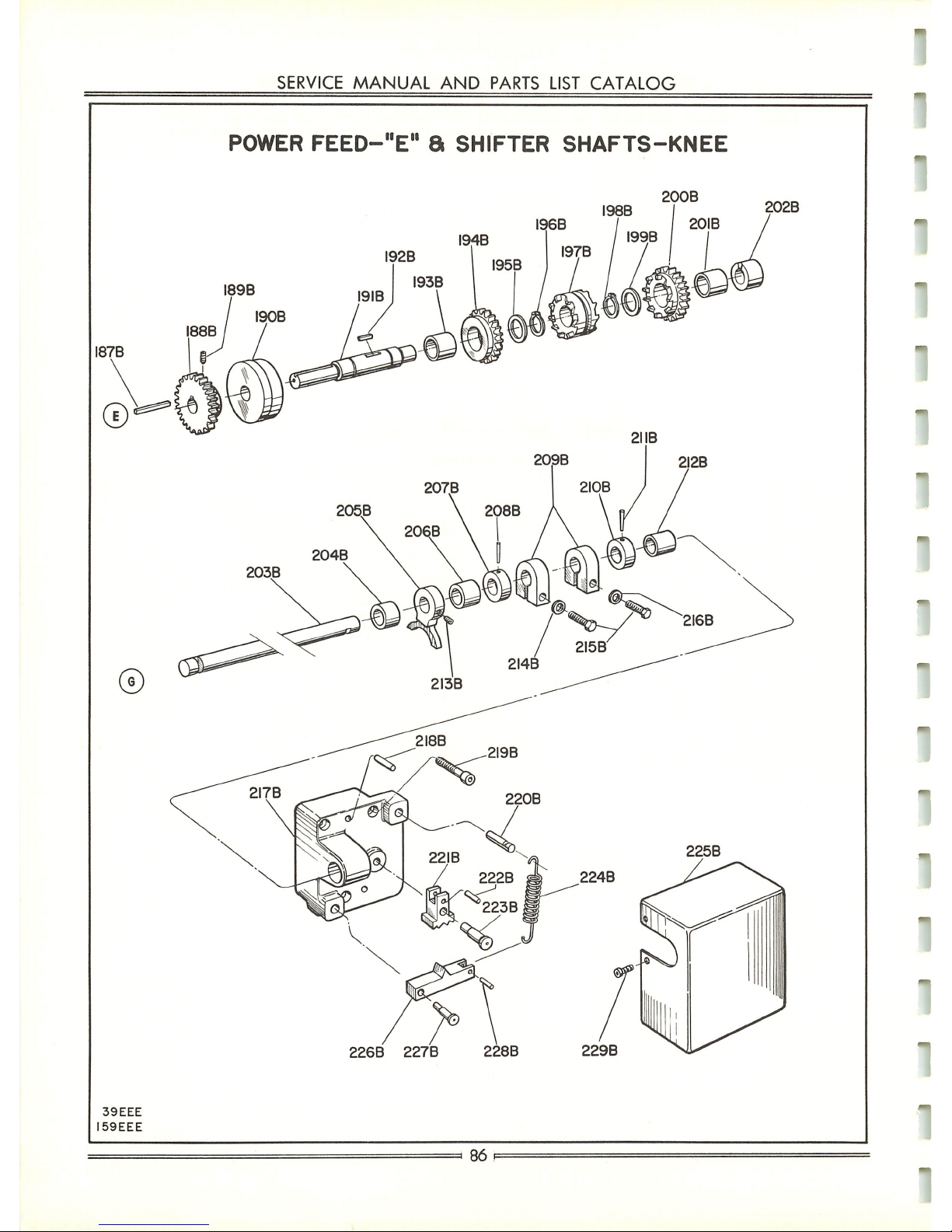
I87B
©
39EEE
I59EEE
SERVICE
MANUAL
AND
PARTS LIST
CATALOG
POWER
FEED-"E"
8
SHIFTER
SHAFTS-KNEE
I94B
207.B
205B
209B
200B
I98B
I96B / I 201B
I99B
I97B
2MB
2I2B
226B
227B
228B
229B
=>
86
202B
Page 88

Key
No.
6JK-187B
6JK-188B
6JK-189B
6JK-190B
6JK-191B
6JK-192B
6JK-193B
6JK-194B
6JK-195B
6JK-196B
6JK-197B
6JK-198B
6JK-199B
6JK-200B
6JK-201B
6JK-202B
6JK-203B
6JK-204B
6JK-205B
6JK-206B
6JK-207B
6JK-208B
CINCINNATI
NO.
1 TOOLMASTER MILLING
MACHINE
WHEN
ORDERING
PARTS,
give
key
number,
part
name
and
part
number.
Be
suretogive
complete
serial
number
for
your
machine.
For
complete
instructions,
see
Page
27,
"HowtoOrder
Repair
Parts."
Part
No.
99199
152399
3226
157761
157759
157762
247565
158182
152315
237432
158183
237432
152315
158181
247565
152383
154422
124668
152382
124668
153070
663
KNEE-UNIT
No. 6JK (Continued)
Part
Name
Key
Gear-Drive
. . .
Screw
Bushing-Bronze
.
Shaft-"E"
. . . .
Key
Bushing-Oilite
.
Gear-Spur
Clutch
.
Spacer
Ring-Truarc
.
Clutch-Reversing
.
Ring-Truarc
. . .
Spacer
Gear-Reversing.
Bushing-Oilite
.
Bushing-Bronze
.
Shaft-Shifting.
. .
Bushing-Bronze
.
Fork-Shifter
. . .
Bushing-Bronze
.
Block-Positive
Stop
Pin-Taper.
WITH
POWERFEED
Amt.
Used
Key
No.
6JK-209B
6JK-210B
6JK-211B
6JK-212B
6JK-213B
6JK-214B
6JK-215B
6JK-216B
6JK-217B
6JK-218B
6JK-219B
6JK-220B
6JK-221B
6JK-222B
6JK-223B
6JK-224B
6JK-225B
6JK-226B
6JK-227B
6JK-228B
6JK-229B
Part
No.
153071
153070
663
154418
3229
246088
1062
246088
150824
3543
2300
3382
157040
230058
154420
93970
154421
155656
155657
3431
3194
Part
Name
Block-Adjusting
Stop
Block-Positive
Stop
Pin-Taper.
. . .
Bushing-Oilite
.
Screw
Washer
Screw
Washer
Bracket-Rear
Pin
Screw
Pin-Spring
Detent-Shifting
Shaft
Pin
Pin-Pivot,
Detent
.
Spring
Cover-Detent.
.
Arm-Detent
. .
Pin-Detent
Arm
. .
Pin
Screw
Amt.
Used
=87=
Publication
No.
M-2109
Page 89

SERVICE
MANUAL
AND
PARTS LIST
CATALOG
POWER
FEED-CROSSFEED
SCREW
a
FRONT
COVER-KNEE
231B
os
30B
\ ^
263B
^Z
266B
39EEE
40EEE
97EEE
269B
270B
y4
A
243
B /
244B
245B
275
B
Page 90

CINCINNATI
NO.
1
TOOLMASTER
MILLING
MACHINE
WHEN
ORDERING
PARTS,
give
key
number,
part
name
and
part
number.
Be
suretogive
complete
serial
number
for
your
machine.
For
complete
instructions,
see
Page
27,
"HowtoOrder
Repair
Parts."
KNEE-UNIT
No. 6JK (Concluded)
WITH
POWERFEED
Key
No.
Part
No.
Amt.
Part
Name
Used
Key
No.
Part
No.
Part
Name
Amt.
Used
6JK-230B
153052
152398
2320
1383
143374
143375
679
679
153067
153068
170756
247024
153072
153476
1844
3251
3369
1900
153060
157563
642
169208
4357
4356
Gear-Saddle
Traversing
1
6JK-252B
6JK-253B
6JK-254B
6JK-255B
6JK-256B
6JK-257B
6JK-258B
6JK-259B
6JK-260B
6JK-261B
6JK-262B
6JK-263B
6JK-264B
6JK-265B
6JK-266B
6JK-267B
6JK-268B
6JK-269B
6JK-270B
6JK-271B
6JK-272B
6JK-273B
6JK-274B
6JK-275B
4352
143371
143372
2008
94710
153051
152393
83512
1266
143701
152394
153050
3202
124501
4093
163681
163680
143377
93985
3399
1383
3229
153053
230058
153073
1
6JK-231B
6JK-232B
Dial-Feed
6JK-233B
Pin
2
6JK-234B
Key
1
Plug
6JK-235B
6JK-236B
Indicator-Cross
Movement
Cover-Front
Oiler
6JK-237B
Key
1
6JK-238B
Screw-Crossfeed
English
1
Bushing-Oilite
Gear-Idler
6JK-239B
Knee
(Alter
per
158521) 1
Plug
1
6JK-240B
Shaft-Idler
Gear
6JK-241B
Nut-Crossfeed
6JK-242B
Plug
1
6JK-243B
6JK-244B
Pin
1
6JK-245B
Pin
1
Plug
6JK-246B
Shaft-Shifter
Arm
1
Bushing-Shifter
Shaft
1
Pin
1
6JK-247B
Pin
6JK-248B
6JK-249B
6JK-250B
6JK-251B
Knob
1
L
=89=
Publication
No.
M-2109
Page 91

SERVICE
MANUAL
AND
PARTS
LIST
CATALOG
COLUMN
AND
COOLANT
PUMP
TURRET
90
Page 92

CINCINNATI
NO.
1
TOOLMASTER
MILLING
MACHINE
WHEN
ORDERING
PARTS,
give
key
number,
part
name
and
part
number.
Be
suretogive
complete
serial
number
for
your
machine.
For
complete
instructions,
see
Page
27,
"HowtoOrder
Repair
Parts."
COLUMN
"
UNIT
No.
COOLANT
PUMP
AND
PIPING
6JC
UNIT
No.
6JP
Key
No.
Part
No.
Part
Name
Amt.
Used
Key
No.
Part
No.
Part
Name
Amt.
Used
6JC-1B
143421
3198
143440
143439
176342
158511
175266
156195
273171
163671
3198
161768
238325
107875
29810
113111
143433
150704
143432
143434
143435
2260
143436
1040
Cover-Drain,
Without
Coolant
Pump
. 1
4
1
1
1
1
1
1
4
1
4
1
2
1
1
1
1
1
1
1
1
1
1
2
6JP-25B
6JP-26B
6JP-27B
6JP-28B
6JP-29B
6JP-30B
6JP-31B
6JP-32B
6JP-33B
6JP-34B
6JP-35B
6JP-36B
6JP-37B
6JP-38B
6JP-39B
6JP-40B
6JP-41B
6JP-42B
6JP-43B
6JP-44B
6JP-45B
Ill
80486
143431
52054
143536
130962
38856
855
3479
166812
10051
24024
143536
80486
143429
133089
89138
143428
2118
3463
153999
156429
6JP-2B
Hose-Neoprene
Valve
Connector-Male
Elbow
Clamp-Supply
Pipe
6JP-3B
6JP-4B
6JP-5B
6JC-6B
6JC-7B
Screen-Coarse
Mesh
Screen-Fine
Mesh
Screw-Stop
Column
(Altered
per
175271
for
Vertical
Movement
Only)
Cover-Electrical
Screw
Cover
(Without
Disconnect
Switch)
. . .
6JNN-8B
Nut
6JC-9B
6JNN-10B
6JNN-11B
Nipple-Close
Elbow-90°
Connector-Male
Tubing-1/2"
Fitting-Adapter
(1/2"
N. P. T. to
1/2"
Tubing)
Bushing-Shoulder
(1/2"to3/4")
. . .
6JP-12B
6JP-13B
6JP-14B
6JP-15B
6JP-16B
6JP-17B
Elbow
Hose-Flexible,
Coolant
6JC-18B
Cover
(Without
Coolant
Pump)
....
Shaft-Pipe
Clamp
6JP-19B
6JP-20B
4
4
6JP-21B
6JP-22B
Pump-Coolant
6JP-23B
Bracket-Pipe
Clamp
Shaft
1
6JP-24B
9\
Publication
No.
M-2109
Page 93

87EEE
7B
SERVICE
MANUAL
AND
PARTS LIST
CATALOG
PRECISION
MEASURING
ATTACHMENT
LONGITUDINAL
MOVEMENT
\>B
23B
2IB
20B
CROSS
MOVEMENT
28B
48B
49B
50B
5IB
52B
53B
92
Page 94

•
CINCINNATI
NO.
1
TOOLMASTER
MILLING
MACHINE
WHEN
ORDERING
PARTS,
give
key
number,
part
name
and
part
number.
Be
suretogive
complete
serial
number
for
your
machine.
For
complete
instructions,
see
Page
27,
"HowtoOrder
Repair
Parts."
PRECISION MEASURING EQUIPMENT
LONGITUDINAL
MOVEMENT
UNIT
No.
6JJL
Key
No.
Part
No.
Part
Name
Amt.
Used
Key
No.
Part
No.
Part
Name
Amt.
Used
6JJL-1B
6JJL-2B
6JJL-3B
143463
2320
3314
143448
664
152060
152061
153975
3486
3314
152301
68266
68265
161846
161847
161848
161849
162323
Trough
- On
Table
Bolt-Tee
1
2
6JJL-14B
6JJL-15B
6JJL-16B
6JJL-17B
6JJL-18B
6JJL-19B
6JJL-20B
6JJL-21B
6JJL-22B
6JJL-23B
6JJL-24B
6JJL-25B
6JJL-26B
6JJL-27B
162324
163640
163641
163643
163644
68270
143460
151499
68716
3277
3329
68269
68271
68267
3399
664
1421
3266
50
M/M
Metric
100
M/M
Metric
200
M/M
Metric
Micrometer
6JJL-4B
6JJL-5B
Nut
6JJL-6B
Dial-Indicator
6JJL-7B
6JJL-8B
Pin-Stop
Pin
6JJL-9B
Bolt-Tee
6JJL-10B
Pin
6JJL-11B
Pin-Lid
6JJL-12B
Screw-Stop,
Indicator
Bracket
....
6JJL-13B
Rod
1"
English
2"
English
8"
English
25
M/M
Metric
2
Nut
1
Pin
2
Screw
2
CROSS
MOVEMENT
Key
No.
Part
No.
Part
Name
Amt.
Used
Key
No.
Part
No.
Part
Name
Amt.
Used
6JJL-28B
6JJL-29B
158505
158503
143458
2320
1421
68270
163643
161846
161847
161848
161849
162323
162324
163640
163641
68265
68266
Knee
Alternation
Bracket-Stop
Pin
1
1
2
2
1
1
1
1
1
1
1
1
1
1
1
1
6JJL-37B
6JJL-38B
6JJL-39B
6JJL-40B
6JJL-41B
6JJL-42B
6JJL-43B
6JJL-44B
6JJL-45B
6JJL-46B
6JJL-47B
6JJL-48B
6JJL-49B
6JJL-50B
6JJL-51B
6JJL-52B
6JJL-53B
152060
152061
68716
3277
143454
2320
1421
3399
143455
3399
1421
3399
68267
143453
68271
68269
3329
153975
Dial-Indicator
6JJL-30B
Pin
6JJL-31B
Pin
6JJL-32B
Pin-Stop
Trough
- On
Knee
6JJL-33B
2
6JJL-34B
Rod
Pin
2
2
2"
English
1
2
8"
English
25
M/M
Metric
50
M/M
Metric
100
M/M
Metric
200
M/M
Metric
Pin
2
2
6JJL-35B
Screw-Stop,
Indicator
Bracket
....
Bracket-Dial,
Indicator
Screw-Indicator
Fastening
Pin-Lid
6JJL-36B
Pin
Cotter
93
=
Publication
No.
M-2109
Page 95

58
EEE
59
EEE
SERVICE
MANUAL
AND
PARTS
LIST
CATALOG
PRECISION
MEASURING
ATTACHMENT
VERTICAL
MOVEMENT
54B
55B
64B
65B
TV
™76B77BK
7IB
72B
/
73B
I
74
B
.
80B
8IB
~94
-78B
-79B
82B
Page 96

•
Key
No.
6JJL-54B
6JJL-55B
6JJL-56B
6JJL-57B
6JJL-58B
6JJL-59B
6JJL-60B
6JJL-61B
6JJL-62B
6JJL-63B
6JJL-64B
6JJL-65B
6JJL-66B
6JJL-67B
6JJL-68B
CINCINNATI
NO.
1 TOOLMASTER MILLING
MACHINE
WHEN
ORDERING
PARTS,
give
key
number,
part
name
and
part
number.
Be
suretogive
complete
serial
number
for
your
machine.
For
complete
instructions,
see
Page
27,
"HowtoOrder
Repair
Parts."
PRECISION
MEASURING
EQUIPMENT-UNIT
No. 6JJL (Concluded)
VERTICAL
MOVEMENT
Part
No.
158520
143465
68271
79004
152060
152061
679
68266
68265
151467
122184
3206
3232
143452
2253
143449
78456
161846
161847
161848
Part
Name
Knee
Alternation
Column
Alteration
Screw-Indicator
Fastening
Case-Indicator
....
Dial-Indicator
English
Metric
Key
Spring-Compression
. .
Plunger-Indicator
Bracket
Screw-Bushing
....
Washer
Screw
Screw
Bracket-Indicator
Dial
Screw
Shaft-Vertical
....
Clip
Rod
1"
English
2"
English
4"
English
Amt.
Used
Key
No.
6JJL-69B
6JJL-70B
6JJL-71B
6JJL-72B
6JJL-73B
6JJL-74B
6JJL-75B
6JJL-76B
6JJL-77B
6JJL-78B
6JJL-79B
6JJL-80B
6JJL-81B
6JJL-82B
Part
No.
161849
162323
162324
163640
163641
163643
163644
68270
143450
151467
122184
3206
3232
3277
68716
68715
158501
1421
3266
75042
Part
Name
8"
English
25
M/M
Metric.
. . .
50
M/M
Metric.
. . .
100
M/M
Metric
. . .
200
M/M
Metric
. . .
Micrometer
English
Metric
Pin-Stop
Bracket-Vertical
Shaft
.
Screw-Bushing
.
Washer
Screw
Screw
Pin
Nut-Pin
Clamping
.
Bolt
Bracket-Stop
Pin
. . .
Pin
Screw
Case-For
Precision
Rods
Amt.
Used
=
95:
Publication
No.
M-2109
Page 97

34B
18
EEE
20
EEE
SERVICE
MANUAL.
AND
PARTS LIST
CATALOG
SHAPING
ATTACHMENT
9B
IOB MB
37B
38B
36B
\-
49
B
96
REF62B
'^"
I
>
\\
'[UJ
y
Ǥ?
28B
t\29B
^O30B
3IB
32B
Page 98

Key
No.
6JHF-1B
6JHF-2B
6JHF-3B
6JHF-4B
6JHF-5B
6JHF-6B
6JHF-7B
6JHF-8B
6JHF-9B
6JHF-10B
6JHF-11B
6JHF-12B
6JHF-13B
6JHF-14B
6JHF-15B
6JHF-16B
6JHF-17B
6JHF-18B
6JHF-19B
6JHF-20B
6JHF-21B
6JHF-22B
6JHF-23B
6JHF-24B
CINCINNATI
NO.
1
TOOLMASTER
MILLING
MACHINE
WHEN
ORDERING
PARTS,
give
key
number,
part
name
and
part
number.
Be
suretogive
complete
serial
number
for
your
machine.
For
complete
instructions,
see
Page
27,
"HowtoOrder
Repair
Parts."
Part
No.
36714
143526
143527
143525
121121
121122
121123
121124
121125
121126
121127
121128
121129
121130
3518
3228
143477
143486
143485
143483
3218
2278
143482
3480
225188
240381
143489
3544
143488
3541
143508
143509
3203
SHAPING
ATTACHMENT
-
UNIT
No.
6JHF
Part
Name
Block-For
Shaping
Tools
. . .
Clamp-Tool,
Outer
Pin-Tool
Stop
Clamp-Tool,
Inner
Tool-Shaping,
Solid
Tool
Holder
1/8"
Parting
3/16"
Parting
1/4"
Square
5/16"
Square
3/8"
Square
1/2"
Square
1/4"
Round
3/8"
Round
1/2"
Round
75° Angle
Pointer
Screw
Slide
Handle-Wrench
Wrench-Stroke
Adjusting
.
Rack-Stroke
Adjusting.
Screw
Screw
Plate-Instruction
Nut
Washer-Heat
Stud
Clamp-Outer
Pin
Clamp-Inner
Pin
Dial-Tool
Index
Bar-Tool
Support
Screw
Amt.
Used
Key
No.
6JHF-25B
6JHF-26B
6JHF-27B
6JHF-28B
6JHF-29B
6JHF-30B
6JHF-31B
6JHF-32B
6JHF-33B
6JM-34B
6JHF-35B
6JHF-36B
6JHF-37B
6JHF-38B
6JHF-39B
6JHF-40B
6JHF-41B
6JHF-42B
6JHF-43B
6JHF-44B
6JHF-45B
6JHF-46B
6JHF-47B
6JHF-48B
6JHF-49B
Part
No.
143511
2333
143510
137917
143512
143513
3227
150709
150710
150711
150712
150713
150714
150715
Example
4093
1632
49
3441
166485
143478
2332
3230
143514
166484
2321
143481
143484
125141
140
Part
Name
Spring - Clapper
Screw
Block-Clapper
Pin-Pivot
Lug-Tool
Clamp
Washer-Tool
Clamp
. . .
Screw
Tool-Clapper
Box
Tool
Holder
Left
Diamond
Point.
. . .
Right
Diamond
Point
. .
Straight,
Round
Nose
. . .
Round
Nose
Diamond
Point
Parting,
Straight
....
Block-For
Shaping
Tools
.
Motor-Shaping
Attachment
(*)
Screw
Key
Screw
Washer
Plate-Motor
Mounting
. .
Housing-Belt
Screw
Screw
Sheave-Motor
Drive
Belt-Vee
Screw
Pin-Belt
Adjusting
....
Screw-Belt
Adjusting
. . .
Knob-Knurled
Pin
Amt.
Used
When
ordering
specify
H. P. ,
frame
size,
voltage
and
cycle.
-91--
Publication
No.
M-2109
Page 99

SERVICE
MANUAL
AND
PARTS
LIST
CATALOG
SHAPING
ATTACHMENT
50B
5IB
98
Page 100

Key
No.
6JHF-50B
6JHF-51B
6JHF-52B
6JHF-53B
6JHF-54B
6JHF-55B
6JHF-56B
6JHF-57B
6JHF-58B
6JHF-59B
6JHF-60B
6JHF-61B
6JHF-62B
6JHF-63B
6JHF-64B
6JHF-65B
6JHF-66B
6JHF-67B
6JHF-68B
6JHF-69B
6JHF-70B
6JHF-71B
6JHF-72B
6JHF-73B
6JHF-74B
6JHF-75B
6JHF-76B
6JHF-77B
6JHF-78B
6JHF-79B
6JHF-80B
6JHF-81B
6JHF-82B
6JHF-83B
6JHF-84B
6JHF-85B
CINCINNATI
NO.
1 TOOLMASTER MILLING MACHINE
WHEN
ORDERING
PARTS,
give
key
number,
part
name
and
part
number.
Be
suretogive
complete
serial
number
for
your
machine.
For
complete
instructions, see Page 27, "How to Order Repair Parts."
Part
No.
143515
3158
225409
143518
143517
4242
221593
108367
3230
2332
1632
143516
143475
143496
3228
95586
95585
3809
3810
143495
143494
3203
3342
143502
143501
4236
143503
143492
76645
143524
741
3480
143506
143505
143504
143507
SHAPING
ATTACHMENT-UNIT
No.
6JHF
(Concluded)
Part
Name
Sheave-Driven
Screw
Seal-Oil
Housing-Oil
Seal,
Large
. .
Gasket-Housing,
Large
. .
Nut-Lock
Cone-Bearing
Cup-Bearing
Screw
Screw
Key
Worm-Shaft
Housing-Gear
Gage-Oil
Sight
Screw
Cup-Bearing
Cone-Bearing
Washer-Lock
Nut
Gasket-Drive
Housing.
Plate-Drive
Housing,
Cover.
Screw
Fitting-Alemite
Pin-Pitman
Mounting
.
Bushing-Pitman,
Small
.
Screw
Pitman
Bolt-Tee
Plug-Pipe
(1/4")
. . . .
Clamp-Screw
Screw
Nut
Washer-Pitman
Bearing
.
Bushing-Pitman,
Large
. .
Sleeve-Bearing
Bolt-Tee
Amt.
Used
Key
No.
6JHF-
6JHF-
6JHF6JHF6JHF6JHF6JHF6JHF6JHF-
6JHF-
6JHF6JHF-
6JHF-
6JHF-
6JHF-
6JHF-
6JHF6JHF6JHF-
6JHF-
6JHF6JHF6JHF-
6JHF-
6JHF-
6JHF6JHF6JHF-
6JHF-
6JHF-
6JHF-
6JHF-
6JHF-
6JHF-
86B
87B
88B
89B
90B
91B
92B
93B
94B
95B
96B
97B
98B
99B
100B
101B
102B
103B
104B
105B
106B
107B
108B
109B
HOB
111B
112B
113B
114B
115B
116B
117B
118B
119B
Part
No.
3274
3442
3479
76645
97288
97289
143519
237219
143520
143521
3218
143522
143523
2291
4236
143487
153499
143476
44980
381
3399
1383
3221
3281
143493
143499
108365
108366
2333
143497
143500
3399
143491
143490
3611
Part
Name
Bolt-Tee
Washer
Nut
Plug
Cup-Bearing
Cone-Bearing
. . . .
Spacer-Worm
Shaft.
Ring-Retaining
.
Gasket-Housing,
Small
Housing-Oil
Seal,
Small
.
Screw
Seal-Oil,
Garlock
. . .
Nut-Eccentric,
Locating
.
Pin
Screw
Clamp-Left,OnHousing
English
Metric
Housing-Slide
.
Oiler
Screw
Screw
Pin
Screw
Key
Crank
Seal-Oil,
Garlock
. . .
Cone-Bearing
. . . .
Cup-Bearing
Screw
Worm-Wheel
Ring-"O"
Screw
Gib-Taper
Clamp-Right,OnHousing
Wrench
Amt.
Used
=
99=
Publication
No.
M-2109
 Loading...