

Page 1

THE CHRYSLER
PACIFICA 2017 USER GUIDE
Page 2

IF YOU ARE THE FIRST REGISTERED RETAIL OWNER OF YOUR VEHICLE, YOU
MAY OBTAIN A COMPLIMENTARY PRINTED COPY OF THE OWNER’S MANUAL,
NAVIGATION/ UCONNECT MANUALS OR WARRANTY BOOKLET BY CALLING
1-800-247-9753 (U.S.) OR 1-800-387-1143 (CANADA) OR BY CONTACTING
YOUR DEALER.
The driver’s primary responsibility is the safe operation of the vehicle. Driving while distracted can
result in loss of vehicle control, resulting in a collision and personal injury. FCA US LLC strongly
recommends that the driver use extreme caution when using any device or feature that may take
their attention o the road. Use of any electrical devices, such as cellular telephones, computers,
portable radios, vehicle navigation or other devices, by the driver while the vehicle is moving is
dangerous and could lead to a serious collision. Texting while driving is also dangerous and should
never be done while the vehicle is moving. If you find yourself unable to devote your full attention
to vehicle operation, pull o the road to a safe location and stop your vehicle. Some states or
provinces prohibit the use of cellular telephones or texting while driving. It is always the driver’s
responsibility to comply with all local laws.
IMPORTANT: This User Guide is intended to familiarize you with the important
features of your vehicle. The DVD enclosed contains your Owner’s Manual, Navigation/
Uconnect Manuals, Warranty Booklets, Tire Warranty and Roadside Assistance (new
vehicles purchased in the U.S.) or Roadside Assistance (new vehicles purchased in
Canada) in electronic format. We hope you find it useful. U.S. residents can purchase
replacement DVD kits by visiting www.techauthority.com and Canadian residents can
purchase replacement DVD kits by calling 1-800-387-1143.
Page 3

TABLE OF CONTENTS
INTRODUCTION
WELCOMEFROMFCAUSLLC .......3
CONTROLS AT A GLANCE
DRIVER COCKPIT ...............6
INSTRUMENT CLUSTER ...........8
GETTING STARTED
VEHICLE USER GUIDE
(U.S. MARKET ONLY) ............10
RKEKEYFOB .................12
REMOTE START — IF EQUIPPED ......17
VEHICLE SECURITY ALARM ........17
KEYLESS ENTER-N-GO — PASSIVE
ENTRY .....................18
KEYLESS ENTER-N-GO — IGNITION . . . 22
SEAT BELT SYSTEMS .............23
SUPPLEMENTAL RESTRAINT SYSTEM
(SRS)—AIRBAGS ..............24
CHILD RESTRAINTS .............31
HEAD RESTRAINTS .............38
FRONTSEATS .................39
REAR SEATS ..................45
HEATED/VENTILATED SEATS .......54
STEERING WHEEL ..............56
OPERATING YOUR VEHICLE
ENGINE BREAK-IN
RECOMMENDATIONS ............58
HEADLIGHT SWITCH ............59
MULTIFUNCTION LEVER ..........61
WINDSHIELD WIPER AND WASHERS . . . 62
SPEED CONTROL ..............64
ADAPTIVE CRUISE CONTROL (ACC) . . . 66
FORWARD COLLISION WARNING
(FCW) .....................70
NINE-SPEED AUTOMATIC
TRANSMISSION ................71
ELECTRIC PARK BRAKE (EPB) .......72
MANUAL CLIMATE CONTROLS ......74
AUTOMATIC TEMPERATURE
CONTROLS (ATC) ..............76
PARKSENSE FRONT AND REAR PARK
ASSIST .....................78
PARKVIEW REAR BACK UP CAMERA —
IF EQUIPPED .................79
SURROUND VIEW CAMERA SYSTEM —
IF EQUIPPED .................80
BLIND SPOT MONITORING ........83
TRI-PANE VISTA VIEW SUNROOF —
IF EQUIPPED .................84
WIND BUFFETING ..............87
ELECTRONICS
YOUR VEHICLE'S SOUND SYSTEM ....88
CYBERSECURITY ...............90
IDENTIFYING YOUR RADIO ........91
UCONNECT ACCESS ............92
UCONNECT 5.0 ...............103
UCONNECT 5.0 VOICE RECOGNITION
QUICKTIPS..................107
UCONNECT 8.4/8.4 NAV ..........114
UCONNECT 8.4/8.4 NAV VOICE
RECOGNITION QUICK TIPS ........127
UCONNECT PHONE . . ..........138
UCONNECT THEATER — IF EQUIPPED
STEERING WHEEL AUDIO CONTROLS
AUX/USB/MP3 CONTROL .........155
INSTRUMENT CLUSTER DISPLAY .....156
PROGRAMMABLE FEATURES .......157
GARAGE DOOR OPENER — IF
EQUIPPED ..................158
POWER INVERTER — IF EQUIPPED ....161
POWER OUTLETS ..............161
. . 148
. . 154
UTILITY
STOW ‘N VAC INTEGRATED VACUUM —
IF EQUIPPED . . . . . . ...........164
TRAILER TOWING WEIGHTS
(MAXIMUM TRAILER WEIGHT
RATINGS) ...................171
RECREATIONAL TOWING .........171
WHAT TO DO IN EMERGENCIES
ROADSIDE ASSISTANCE ..........173
WARNING AND INDICATOR LIGHTS . . . 173
IF YOUR ENGINE OVERHEATS ......181
TIRE SERVICE KIT — IF EQUIPPED ....181
JACKING AND TIRE CHANGING —
IF EQUIPPED .................188
JUMP-STARTING ..............200
MANUAL PARK RELEASE . . .......203
TOWING A DISABLED VEHICLE .....204
FREEING A STUCK VEHICLE .......206
ENHANCED ACCIDENT RESPONSE
SYSTEM (EARS) ...............207
EVENT DATA RECORDER (EDR) .....207
MAINTAINING YOUR VEHICLE
HOOD ....................208
ENGINE COMPARTMENT — 3.6L . . . . . 210
FLUIDCAPACITIES .............212
FLUIDS AND LUBRICANTS .........212
FLEXIBLE FUEL — IF EQUIPPED .....214
MAINTENANCE PROCEDURES ......214
MAINTENANCE SCHEDULE ........214
FUSES .....................219
ADDING FUEL . . ..............223
TIRES — GENERAL INFORMATION . . . 224
REPLACEMENT BULBS ...........227
Page 4

TABLE OF CONTENTS
CONSUMER ASSISTANCE
FCA US LLC CUSTOMER CENTER ....228
FCA CANADA INC. CUSTOMER
CENTER ...................228
ASSISTANCE FOR THE HEARING
IMPAIRED ..................228
PUBLICATIONS ORDERING ........228
REPORTING SAFETY DEFECTS IN THE
UNITEDSTATES ...............229
MOPAR® ACCESSORIES
AUTHENTIC ACCESSORIES BY MOPAR
. . 230
FAQ’S
FREQUENTLY ASKED QUESTIONS ....231
INDEX
...................232
2
Page 5

INTRODUCTION
WELCOME FROM FCA US LLC
Congratulations on selecting your new FCA US LLC (“FCA US”) vehicle. Be assured that it
represents precision workmanship, distinctive styling, and high quality.
Your new FCA US vehicle has characteristics to enhance thedriver's control under some driving
conditions. These are to assistthe driver and arenever a substitute for attentivedriving. They can
never take the driver's place. Always drive carefully.
Your new vehicle hasmanyfeaturesfor the comfort and convenienceofyou and your passengers.
Some of these should not be used when driving because they take your eyes from the road or
your attention from driving.Nevertext while driving ortakeyour eyes more than momentarilyoff
the road.
This guide illustratesand describes the operation of features andequipment that are either standard
or optional on this vehicle. This guide may also include adescription of featuresand equipment that
are no longer available or were not ordered on this vehicle. Please disregard any features and
equipment described in this guide that are notavailable on this vehicle. FCAUS reserves the rightto
make changes in designandspecifications and/or make additions toor improvements to its products
without imposing any obligation upon itself to install them on products previously manufactured.
This User Guide has been prepared to help you quickly become acquainted with the important
features of your vehicle. It contains mostthings you will needto operate and maintain thevehicle,
including emergency information.
The DVD includes a computer application containing detailed Owner's information which can
be viewed on a personalcomputeror MAC computer.Themultimedia DVDalso includes videos
which can be played on any standard DVD player (including the Uconnect Touchscreen Radios
if equipped with DVD player capabilities).AdditionalDVDoperationalinformation is located on
the back of the DVD sleeve.
For complete owner information, refer toyour Owner's Manual on the DVDin the owner’s
kit provided at the time of new vehicle purchase. For your convenience, the information
contained on the DVD may also be printed and saved for future reference.
FCA US is committed to protecting our environment and natural resources. By converting from
paper to electronic delivery for the majority ofthe user information for your vehicle,together we
greatly reduce the demand for tree-based products and lessen the stress on our environment.
3
Page 6
INTRODUCTION
VEHICLES SOLD IN CANADA
With respect to any vehicles sold in Canada, the name FCA US LLC shall be deemed to be
deleted and the name FCA Canada Inc. used in substitution (excluding legal lines).
WARNING!
• Pedals that cannot move freely can cause loss of vehicle control and increase the risk of
serious personal injury.
• Always make sure that objects cannot fall into the driver foot well while the vehicle is
moving. Objects canbecome trapped under thebrakepedal and accelerator pedalcausing
a loss of vehicle control.
• Failure to properly follow floor mat installation or mounting can causeinterference with the
brake pedal and accelerator pedal operation causing loss of control of the vehicle.
• Never leave children alone in a vehicle, or with access to an unlocked vehicle. Allowing
children to be in a vehicle unattended is dangerous for a number of reasons. A child or
others could be seriously or fatally injured. Children should be warned not to touch the
parking brake, brake pedal or the transmission gear selector.
• Do not leavethe key fob in ornear the vehicle, or in alocation accessible to children. Achild
could operate power windows, other controls, or move the vehicle.
• Never use the ‘PARK’ position as a substitute for the parking brake. Always apply the
parking brake fully when parked to guard against vehicle movement and possible injury or
damage.
• Refer to your Owner's Manual on the DVD for further details.
4
Page 7

INTRODUCTION
USE OF AFTERMARKET PRODUCTS (ELECTRONICS)
The use of aftermarket devices including cell phones, MP3 players, GPS systems, or chargers
may affect the performance of on-board wireless features including Keyless Enter-N-Go and
Remote Start range. If you are experiencing difficulties with any of your wireless features, try
disconnecting your aftermarket devicesto see if thesituation improves. If your symptomspersist,
please see an authorized dealer.
When it comes to service, remember that your authorized dealer knows your vehicle best, has
factory-trained technicians and genuine MOPAR® parts, and cares about your satisfaction.
5
Page 8

CONTROLS AT A GLANCE
DRIVER COCKPIT
1. Headlight Switch pg. 59
2. Turn Signal/High Beams Lever (behind steering wheel) pg. 61
3. Instrument Cluster Display pg. 8
4. Windshield Wiper And Washers pg. 62
5. Keyless Enter-N-Go — Ignition pg. 22
6. Identifying Your Audio System pg. 91
7. Storage Compartment
6
Page 9

CONTROLS AT A GLANCE
8. Switch Panel
• Park Assist pg. 78
• ParkSense pg. 78
• Keyless Enter-N-Go — Ignition pg. 22
• LaneSence OFF
• Electronic Stability Control (ESC) OFF
9. Climate Controls pg. 76
10. Gear Selector pg. 71
11. Speed Controls pg. 64
12. Instrument Cluster Display Controls pg. 156
13. Driver Seat Memory Settings pg. 43
14. Power Window/Door Lock switch Panel
7
Page 10

CONTROLS AT A GLANCE
INSTRUMENT CLUSTER
1. Tachometer
2. Temperature Gauge
3. Instrument Cluster Display
(See page 173 for more Instrument Cluster Warning Light information.)
8
Page 11

CONTROLS AT A GLANCE
4. Fuel Gauge
5. Speedometer
(See page 177 for more Instrument Cluster Indicator Light information.)
9
Page 12

GETTING STARTED
VEHICLE USER GUIDE (U.S. MARKET ONLY)
Access your Owner’s Information – right through your Uconnect 8.4 or 8.4 NAV touchscreen
system — If Equipped (See page 91 for Identifying your radio).
To access the Vehicle User Guide on your Uconnect Touchscreen: Push the Uconnect Apps
button, then push the Vehicle User Guide icon on your touchscreen.
NOTE:
Vehicle User Guide featuresarenotavailable while the vehicle is moving.Ifyoutry to access while
the vehicle is in motion, thesystemwill display: Featurenot available while the vehicle is inmotion.
Pre-Installed Features
•
Your User Guide — Updated in real-time
•
Touchscreen convenience
•
Maintenance schedules and information
•
Comprehensive icon & symbol glossary
•
Available when and where you need it
•
Customizable interface
•
Multilingual
Vehicle User Guide Home Screen
Once you launch your Vehicle User Guide, you will be able to explore your warranty information
and radio manual when and where you need them. Your Uconnect radio will display the Vehicle
User Guide on your touchscreen radio to assist in better understanding your vehicle. There’s no
app to download, no phone to connect and no external device needed for playback. Plus, it’s
updated throughout the year, in real-time, so it never goes out of date.
10
Page 13

GETTING STARTED
Features/Benefits
• Pre-installed on your Uconnect touchscreen radio
• Enhanced search and browsing capability
• Robust NAV application — If Equipped
• Add selected topics to a fast-access Favorites category
• Icon and symbol glossary
• Warranty information
• Crucial driver information and assistance:
•
Operating Instructions
•
Warranty Information
•
Fluid Level Standards
Tip: When viewing a topic, tap the star icon to add it to your Favorites, for easy access in the
future.
•
Maintenance Schedules
•
Emergency Procedures
•
911 Contact and More
Enhanced Search And Browsing Capability Icon And Symbol Glossary
11
Page 14

GETTING STARTED
RKE KEY FOB
Description Of RKE Key Fob
The keyless ignition system consists of a Key Fob with Remote Keyless Entry (RKE) transmitter
(RKE Key Fob) and a keyless push button Ignition system.
NOTE:
Key fob features may vary depending upon
vehicle build options, refer to your Owner’s
Manual on the DVD for additional information
regarding your key fob features.
Locking The Doors With A RKE Key Fob
Push and release the LOCK button onthe RKE
Key Fob to lock all doors and liftgate. The turn
signal lights will flash and the horn will chirp to
acknowledge the signal.
NOTE:
Refer to “Uconnect Settings” in “Multimedia” in
your Owner’s Manual on the DVD for further
information to program your preferred settings
for the light flash and horn chirp functions.
If the vehicle is equipped with Passive Entry,
refer to “Keyless Enter-N-Go — Passive Entry”
in this guide for further information.
Key Fob With Remote Control And
Integrated Vehicle Key
If one or more doors are open, or the liftgate is
open, the doors will lock. This is signaled by a quick flash of the turn signals.
Vehicles Equipped With Keyless Enter-N-Go — Passive Entry
If one or more doors are open, or the liftgate is open, the doors will lock. The doors will unlock
again only if the key fob is inside the passenger compartment.
NOTE:
• The default lock setting can be changed within Uconnect Settings so that the system will
allow/inhibit the ability to lock the doors when one or more doors/liftgate are open.
• For additional information, refer to “Uconnect Settings” in “Multimedia” in your Owner’s
Manual on the DVD.
1 — Unlock
2—Lock
3 — Remote Start
4 — Right Power Sliding Side Door
5 — Panic Alarm
6 — Emergency Key
7 — Left Power Sliding Side Door
8 — Liftgate
RKE Key Fob
12
Page 15

GETTING STARTED
Unlocking The Doors With A RKE Key Fob
NOTE:
The key fob unlock procedure is programmable through your “Uconnect Setting” for either of
the following programmable setting:
• 1st press of the RKE Key Fob unlocks only the driver side passenger entry doors (front/side
sliding doors).
• 1st press of the RKE Key Fob unlocks “ALL” passenger entry doors and liftgate.
1st Push Of RKE Key Fob Unlocks Driver Side Passenger Entry Doors
Push and release the UNLOCK button on the RKE Key Fob once to unlock the driver front and
driver side passenger entry doors. The turn signal lights will flash to acknowledge the unlock
signal. The illuminated entry system will be activated
Push and release the UNLOCK button on the RKE Key Fob twice within five seconds to unlock
all doors and liftgate. The turn signal lights will flash to acknowledge the unlock signal. The
illuminated entry system will be activated.
1st Push Of RKE Key Fob Unlocks All Passenger Entry Doors And Liftgate
Push and release the UNLOCK button on the RKE Key Fob once to unlock “ALL” passenger
entry doors and liftgate. The turn signal lights will flash to acknowledge the unlock signal. The
illuminated entry system will be activated
NOTE:
For additional programming information, refer to “Uconnect Settings” in “Multimedia” in your
Owner’s Manual on the DVD.
Panic Alarm
Push the PANIC button once to turn the Panic Alarm on.
To cancel the Panic Alarm wait approximately three seconds and push the PANIC button a
second time to turn the Panic Alarm off.
13
Page 16

GETTING STARTED
Power Liftgate
Unlocking/Enter The Liftgate Using The RKE Key Fob
The power liftgate may be opened by pulling the liftgate release or by using the button on the
RKE Key Fob. Push the button twice within five seconds, to open the power liftgate.
The power liftgate may also be opened by pushing the button located on the overhead console.
NOTE:
• If anythingobstructs the power liftgate while it isclosing or opening, the liftgate will automatically reverse to the closed or open position, provided it meets sufficient resistance.
• There are also pinch sensors attached to the side of the liftgate opening. Light pressure
anywhere along these strips will cause the liftgate to return to the open position.
• During power operation, whether liftgate is fully open or fully closed, the liftgate chime will
beep several times indicating power operation is in progress.
• The powerliftgate must be in thefull open or closepositions for any of the buttons to operate.
If the liftgate is not in the full open or close positions, it must be opened or closed manually.
• If the liftgate release button is activated while the power liftgate is closing, the liftgate will
reverse to the full open position.
• The power liftgate buttons will not operate if the gear selector is in gear or the vehicle speed
is above 0 mph (0 km/h).
• The power liftgate will not operate in temperatures below −12° F (−24° C) or temperatures
above 143° F (62° C). Be sure to remove any buildup of snow or ice from the liftgate before
pushing any of the power liftgate buttons.
• If the power liftgate encounters multiple obstructions within the same cycle, the system will
automatically stop and must be opened or closed manually.
• In the event of a power malfunction to the liftgate, an emergency liftgate latch release can be
used to open the liftgate. The emergency liftgate latch release can be accessed through a
snap-in cover located on the liftgate trim panel.
• If the liftgate is left open for an extended period of time, the liftgate may need to be closed
manually to reset power liftgate functionality.
WARNING!
• Driving with the liftgate open can allow poisonous exhaust gases into your vehicle. You and
your passengers could be injured by these fumes. Keep the liftgate closed when you are
operating the vehicle.
• If youarerequired to drive with theliftgate open, make surethat all windows are closed,and
the climate control blower switch is set at high speed. Do not use the recirculation mode.
Gas props support the liftgate in the open position. However, because the gas pressure drops with
temperature, it may be necessary to assist the props when opening the liftgate in cold weather.
14
Page 17

GETTING STARTED
Power Sliding Doors
Push the LEFT or RIGHT Power Sliding Door button twice within five seconds to power
open/close the Power Sliding Door. If the button is pushed again while the door is being power
closed, the door will reverse to the full open position.
KeySense Features – If Equipped
This feature provides the vehicle owner with the ability to identify a specific vehicle
key for which a customized category of vehicle settings can be applied to determine
the driving experience for other drivers of the vehicle. The vehicle settings are
protected by a unique 4-digit PIN, which the vehicle owner creates when accessing
the specific settings for the first time.
This feature also has additional featuresthat are always enabled when the specific key
is in use that cannot be set by the vehicle owner. While this specific key is in use, the
vehicle will respondaccordingly to thecustomized vehicle settingsand mandatory features. This
includes enhanced driving assistance features, increased driver alerts, and the locking of certain
optional features.
KeySense Unique Splash Screen
At start-up theKeySense splash screen should inform thedriver that the vehicle will be functioning in KeySense mode when the KeySense key is in use.
Start Up Instrument Cluster Display Features
• Unique splash screen graphic
• Telltale illuminated
• After unique splash screen, and after stored messages are cycled, then start-up KeySense
messages (Range & Max Speed) are displayed.
The following features are always enabled when this key is in use:
• Entertainment Audio Muted if 1st row Seatbelts are not Fastened
• Consistent Seat belt Unfastened Chime
• Maximum Radio Volume
• Daytime Running Lights
Please refer to “Keys” in “GettingTo Know Your Vehicle” in your Owner’s Manualon the DVD for
further information.
Key-
Sense
Telltale
Emergency Key
Should the battery in the vehicle or the RKE Key Fob godead, there is anemergency key located
in the RKE Key Fob that can be used for locking and unlocking the doors. To remove the
emergency key, slide the button at the top of the RKE Key Fob sideways with your thumb and
then pull the key out with your other hand.
The emergency key is used to unlock/lock the driver's door and the glove compartment.
15
Page 18
GETTING STARTED
In case the RKE Key Fob battery is dead, use the emergency key to open the door. If the vehicle
is equipped with Keyless Enter-N-Go — Ignition, remove the keyless ignition push button by
inserting the metal partofthe emergency key under the buttonbezel at the 6 o’clock positionand
gently pry the button loose.
NOTE:
The keyless ignition push button should only be removed or inserted with the ignition in the
LOCK position (OFF position for Keyless Enter-N-Go — Ignition).
With the keyless ignition push button removed, start the vehicle by inserting the emergency Key
Fob in the ignition and turning to the Start position.
CAUTION!
• If your vehicle battery becomes low or dead, your Key Fob will become locked in the
ignition.
• Do not attempt to remove the Key Fob while in this condition, damage could occur to the
Key Fob or ignition module.Only remove the emergency key for locking and unlocking the
doors.
• Leave the Key Fob in the ignition and either:
• Jump Start the vehicle.
• Charge the battery.
• Contact your authorized dealer for assistance on how to remove the Key Fob using
the manual override method.
WARNING!
• Never leave children alone in a vehicle, or with access to an unlocked vehicle. Allowing
children to be in a vehicle unattended is dangerous for a number of reasons. A child or
others could be severely injured or killed. Children should be warned not to touch the
parking brake, brake pedal, or the transmissiongear selector.Donot leave the RKE Key Fob
inside the vehicle, or in a location accessible to children, and do not leave the ignition of a
vehicle equipped with Keyless Enter-N-Go in the ACC or ON/RUN mode. A child could
start the vehicle, operate power windows, other controls, or move the vehicle.
• Do not leavechildrenor animals inside parked vehicles inhot weather.Interiorheatbuild-up
may cause them to be severely injured or killed.
• Keep RKE Key Fobs away from children. Operationof the Remote Start System, windows,
door locks or other controls could cause serious injury or death.
• Driving with the liftgate open can allow poisonous exhaust gases into your vehicle. You and
your passengers could be injured bythese fumes.Keep the flipperglassclosed when you are
operating the vehicle.
16
Page 19
GETTING STARTED
REMOTE START — IF EQUIPPED
Push the REMOTE START button on the RKE Key Fob twice within five seconds. Pushing
the REMOTE START button a third time shuts the engine off.
To drive the vehicle, push the UNLOCK button on the RKE Key Fob, place the ignition in the
ON/RUN position by pushing the keyless push button.
With Remote Start, the engine will only run for 15 minutes (timeout) unless the keyless push
button ignition is placed in the ON/RUN position.
The vehicle mustbe started with thekeyless push button ignitionafter two consecutive timeouts.
WARNING!
• Do not start or run an engine in a closed garage or confined area. Exhaust gas contains
Carbon Monoxide (CO) which is odorless and colorless. Carbon Monoxide is poisonous
and can cause you or others to be severely injured or killed when inhaled.
• Keep RKE Key Fobs away from children. Operationof the Remote Start System, windows,
door locks or other controls could cause you and others to be severely injured or killed.
VEHICLE SECURITY ALARM
The Vehicle SecurityAlarmmonitorsthe vehicle doors for unauthorized entryandtheignition for
unauthorized operation. While the Vehicle Security Alarm is armed, interior switches for door
locks and liftgate releasearedisabled. If something triggers thealarm, the VehicleSecurity Alarm
will provide the following audible and visible signals: the horn will pulse, the park lamps and/or
turn signals will flash, and the Vehicle Security Light in the instrument cluster will flash.
To Arm Your Alarm
Push the keyless ignition push buttonuntilthe instrument cluster display indicatesthatthe vehicle
ignition is “OFF.” Push the power door lock switch while the door is open, push the RKE Key Fob
LOCKbutton, or with one of theRKE Key Fobs located outside the vehicle andwithin 5 ft (1.5 m)
of the driver's and passenger front door handles, push the passive entry button located on the
door handle.
NOTE:
After pushing the RKE Key Fob LOCK button, you must wait two seconds before you can lock
or unlock the vehicle via the door handle.
To Disarm Your Alarm
Push the UNLOCK buttonon the RKE KeyFobor with one of the RKE Key Fob located outside
the vehicle and within 5 ft (1.5 m) of the driver's and passenger front door handles, grab the
Keyless Enter-N-Go — Passive Entry door handle and enter the vehicle, then push the keyless
push button ignition (requires at least one valid RKE Key Fob in the vehicle).
17
Page 20

GETTING STARTED
KEYLESS ENTER-N-GO — PASSIVE ENTRY
The Keyless Enter-N-Go system is an enhancementtothe vehicle’s Remote Keyless Entry (RKE)
feature. This feature allows you to lock and unlock the vehicle's door(s) and liftgate without
having to push the RKE Key Fob LOCK or UNLOCK buttons, as well as starting and stopping
the vehicle with the push of a button.
To Unlock From The Driver or Passenger Side
With a valid RKE Key Fob located outside the
vehicle and within 5 ft (1.5 m) of the driver or
passenger side door handle, grab either front
door handle to unlock the door automatically.
Grab The Door Handle To Unlock
To Lock The Vehicle
The passive entry front door and sliding door handles have buttons located on the outside of the
handle. With one ofthe vehicles RKE KeyFobslocated outside the vehicle and within 5ft (1.5 m)
of the driver's (front and sliding door) or passenger (front and sliding door) handles, push the
door handle button to lock all four doors and liftgate.
NOTE:
The passive entry system my be programed through Uconnect Setting to meet your needs.
Refer to “Uconnect Customer Programmable Features” for further information.
18
Page 21

GETTING STARTED
DO NOT grab the door handle, when pushing the door handle button. This could unlock the
door(s).
Push The Door Handle Button To Lock
NOTE:
• After pushing the door handle button, you must wait two seconds before you can lock or
unlock the doors, using either Passive Entry door handle. This is done to allow you to check if
the vehicle is locked by pulling the door handle, without the vehicle reacting and unlocking.
• The Passive Entry system will not operate if the RKE Key Fob battery is dead.
The vehicle doors can also be locked by using the RKE Key Fob lock button, or the lock button
located on the vehicles interior door panel.
Do Not Grab The Door Handle When Locking
Lock Or Unlock The Power Liftgate
With a valid Passive Entry RKEKeyFobwithin 5 ft (1.5 m)of the liftgate, cycle the handleto open
the liftgate and pull the liftgate open with one fluid motion.
NOTE:
•
All doors will remain locked when the liftgate release handle is pushed regardless of the driver’s
door unlock preference setting (“Unlock Driver Door 1st Press” or “Unlock All Doors 1st Press”).
• Refer to “Keyless Enter-N-Go — Passive Entry” in “Getting To Know Your Vehicle” in your
Owner's Manual on the DVD for further information.
19
Page 22

GETTING STARTED
Hands-Free Sliding Doors – If Equipped
Hands-Free Feature
Make sure you have an RKE Key Fob within 3 ft (1 m) of the sliding side doors.
1. Move your foot under and away from the
center of the sliding door detection area in a
single-kick motion. Do not move your foot
sideways or the sensors may not detect the
motion.
2. The sliding side doors will power open or
close.
NOTE:
Allow the power system toopenthe sliding side
door(s). Manually pushing orpullingthe sliding
side door may activate the system’s obstacle
detection feature and stop the poweroperation
or reverse its direction. Manually interfering with the sliding side door motion may also cause an
open/close failure.
NOTE:
Splashing water may cause the Hands-Free Sliding Door to open. Keep the RKE Key Fob away
from the rear bumper detection area when washing your vehicle.
Obstacle Detection
The system stops when it detects an obstacle. Two short tones soundand the system will reverse
to the open or closed position. When you remove the obstacle, you canpower open or close the
sliding side door.
If the sliding side door encounters multiple obstructions within the same cycle, the system will
automatically stop. If this occurs, the sliding side door must be opened or closed manually.
The sliding side door will not power open or close if the gear selector is in gear or the vehicle
speed is above 0 MPH (km/h).
NOTE:
Entering your vehicle while the sliding side door is closing can cause your vehicle to bounce and
activate obstacle detection. To prevent this, let the sliding side door close completely before you
enter your vehicle. Before driving off, check the instrument cluster for a sliding side door ordoor
open message or warning indicator. Failure to do this could result in unintentionally leaving the
sliding side door open while driving.
NOTE:
Disable the Hands-Free Sliding Door feature through Uconnect during the following:
• Vehicle Servicing
• Jacking and Tire Changing
Hands-Free Sliding Doors
20
Page 23

GETTING STARTED
Hands-Free Liftgate – If Equipped
To open or close the liftgate using hands-free activation, use a gentle straight forward and back
kicking motion under the vehicle activation zone in the general location below the liftgate door
handle. Do not move your foot sideways or in a sweeping motion or the sensors may not detect
the motion.
NOTE:
If your vehicle is equipped with theTrailer Tow Package, the hands-freeactivation zone(s) for the
Power Liftgate will be located on the left and right side of the receiver. Use the same gentile
straight kicking motion under either activation zone to open/close the Hands-Free Liftgate.
Hands-Free Liftgate Activation Zone Hands-Free Liftgate Activation Zones With
Trailer Tow package
To open or close the Hands-Free Liftgate requires a valid Passive Entry RKE Key Fob within 3 ft
(1 m) of the door handle. If a valid Passive Entry RKE Key Fob is not within 3 ft (1 m), the liftgate
will not respond to any kicks.
1. Move your foot straight forward and back under the rear bumper activation zone in a gentle
single-kicking motion. Do not move your foot sideways or the sensors may not detect the
motion.
2. The liftgate powers open or close.
NOTE:
Allow the power system toopen the liftgate. Manually pushing or pullingthe liftgate may activate
the system’s obstacle detection feature and stop the power operation or reverse its direction.
Manually interfering with the liftgate motion may also replicate a gas strut failure.
NOTE:
Splashing water may cause the Hands-Free Liftgate to open. Keep the RKE Key Fob away from
the rear bumper detection area when washing your vehicle.
21
Page 24

GETTING STARTED
Obstacle Detection
The system stops when it detects an obstacle. Two short tones sound and the system reverses to
the open or closed position. When you remove the obstacle, you can power open or close the
liftgate.
NOTE:
Entering your vehicle while the liftgate is closing can cause your vehicle to bounce and activate
obstacle detection. To prevent this, let theliftgate closecompletelybeforeyou enter your vehicle.
Before driving off, check the instrument cluster for a liftgate or door open message or warning
indicator. Failure to do this could result in unintentionally leaving the liftgate open while driving.
NOTE:
Disable the Hands-Free Liftgate feature through Uconnect during the following:
• Vehicle Servicing
• Jacking and Tire Changing
KEYLESS ENTER-N-GO — IGNITION
Starting
Perform the following starting procedure with a Remote Keyless Entry(RKE) Key Fob insidethe
vehicle:
1. Place the gear selector in PARK or NEUTRAL.
2. While depressing the brake pedal, push the ENGINE START/STOP button once. If the
engine fails to start, the starter will disengage automatically after 10 seconds.
3. To stop the cranking of the engine prior to the engine starting, push the button again.
Stopping
1. Bring the vehicle to a complete stop.
2. Shift the transmission to PARK (P).
3. Push the ENGINE START/STOP button once. The ignition switch will return to the OFF
position.
NOTE:
If the transmission is not in PARK and the vehicle is in motion, the ENGINE START/STOP
button must be held for two seconds with the vehicle speed above 5 mph (8 km/h) before the
engine will shut off.
22
Page 25
GETTING STARTED
SEAT BELT SYSTEMS
Lap/Shoulder Belts
All seating positions in your vehicle are equipped with lap/shoulder belts.
Be sure everyone in your vehicle is in a seat and using a seat belt properly.
Position the lap belt so that it is snug and lies low across your hips, below your abdomen. To
remove slack in the lap belt portion, pull up on the shoulder belt. To loosen the lap belt if it is too
tight, tilt the latch plateand pull on the lap belt. A snugseat belt reduces the risk of sliding under
the seat belt in a collision.
Position the shoulder belt across the shoulder and chest with minimal, if any slack so that it is
comfortable and not resting on your neck. The retractor will withdraw any slack in the shoulder
belt.
Seat Belt Pretensioner
The front seat belt system is equipped with pretensioning devices that are designed to remove
slack from the seat belt in the event of a collision.
A deployed pretensioner or a deployed air bag must be replaced immediately.
WARNING!
• In a collision, you and your passengers can suffer much greater injuries if you are not
properly buckled up. You can strike the interior of your vehicle or other passengers, or you
can be thrown out of the vehicle. Always be sure you and others in your vehicle arebuckled
up properly.
• A shoulderbelt placed behind you willnotprotect you from injury duringa collision. You are
more likely to hit your head in a collision if you do not wear your shoulder belt. The lap and
shoulder belt are meant to be used together.
• A seat belt that is too loose will not protect youproperly. In a suddenstop, you could move
too far forward, increasing the possibility of injury. Wear your seat belt snugly.
• A frayed or torn seat belt could rip apart in a collision and leave you with no protection.
Inspect the seat belt system periodically, checking for cuts, frays, or loose parts. Damaged
parts must be replaced immediately. Do not disassemble or modify the system. Seat belt
assemblies must be replaced after a collision.
23
Page 26

GETTING STARTED
SUPPLEMENTAL RESTRAINT SYSTEM (SRS) — AIR BAGS
Air Bag System Components
Your vehicle may be equipped with the following air bag system components:
• Occupant Restraint Controller (ORC)
• Air Bag Warning Light
• Steering Wheel and Column
• Instrument Panel
• Knee Impact Bolsters
• Advanced Front Air Bags
• Supplemental Side Air Bags
• Supplemental Knee Air Bags
• Front and Side Impact Sensors
• Seat Belt Pretensioners
• Seat Belt Buckle Switch
• Seat Track Position Sensors
• Occupant Classification System
Advanced Front Air Bags
This vehicle has Advanced Front Air Bags for both the driver and front passenger as a supplement to the seat beltrestraintsystems.The Advanced Front Air Bags will not deployinevery type
of collision.
Advanced Front Air Bags are designed to provide additional protection by supplementing the
seat belts. Advanced Front Air Bags are not expected to reduce the risk of injury in rear, side, or
rollover collisions.
The Advanced Front Air Bags will not deploy in all frontal collisions, including some that may
produce substantial vehicle damage — for example, some pole collisions, truck underrides, and
angle offset collisions.
On the other hand, depending on the type and location of impact, Advanced Front Air Bags may
deploy in crashes with little vehicle front-end damage but that produce a severe initial deceleration.
Because air bag sensors measure vehicle deceleration over time, vehicle speed and damage by
themselves are not good indicators of whether or not an air bag should have deployed
Seat belts are necessary for your protection in all collisions, and alsoare needed tohelp keep you
in position, away from an inflating air bag.
After any collision, the vehicle should be taken to an authorized dealer immediately.
24
Page 27
GETTING STARTED
Do not drive your vehicleafterthe air bags have deployed.Ifyou are involved in another collision,
the air bags will not be in place to protect you.
If it is necessaryto modify the airbag system for personswith disabilities, contact your authorized
dealer.
Refer to the Owner's Manual on the DVD for further details regarding the Supplemental
Restraint System (SRS).
Occupant Classification System
This vehicle is equipped with a right front passenger Occupant Classification System (“OCS”)
that is designed to provide Passenger Advanced Front Air Bag output appropriate to the
occupant’s seated weight input, as determined by the OCS.
The Occupant Classification System (OCS) consists of the following:
• Occupant Restraint Controller (ORC)
• Occupant Classification Module (OCM) and Sensor located in the front passenger seat
• Air Bag Warning Light
The OCS will NOT prevent deployment of the Passenger Advanced Front Air Bag. The OCS may
reduce the inflation rate of the Passenger Advanced Front Air Bag if the OCS estimates that:
• The front passenger seat is unoccupied or has very light objects on it; or
• The front passenger seat is occupied by a small passenger, including a child; or
• The front passenger seat is occupied by a rear-facing child restraint; or
• The front passenger is not properly seated or his or her weight is taken off of the seat for a
period of time.
Front Passenger Seat Occupant Status Front Passenger Air Bag Output
Rear-facing child restraint Reduced-power deployment
Child, including a child in a forward-facing child
restraint or booster seat*
Properly seated adult
Unoccupied seat Reduced-power deployment
Reduced-power deployment OR Full-power
deployment
Full-power deployment OR reduced-power
deployment
* It is possible for a child to be classified as an adult, allowing a full-power Passenger Advanced
Front Air Bag deployment. Never allow children to ride in the front passenger seat and never
install a child restraint system, including a rear-facing child restraint, in the front passenger seat.
The OCS determines the front passenger’s most probable classification.
25
Page 28

GETTING STARTED
The OCS estimates the seated weight on the front passenger seat and where that weight is
located. The OCS communicates the classification status to the ORC. The ORC uses the
classification to determine whether the Passenger Advanced Front Air Bag inflation rate should
be adjusted. In order for the OCS to operate as designed, it is important for the front passenger
to be seated properly and properly wearing the seat belt. Properly seated passengers are:
• Sitting upright
• Facing forward
• Sitting in the center of the seat with their feet comfortably on or near the floor
• Sitting with their back against the seatback and the seatback in an upright position
Lighter Weight Passengers
(Including Small Adults)
When a lighter weight passenger, including a
small adult, occupies the front passenger seat,
the OCS may reduce the inflation rate of the
Passenger Advanced Front Air Bag. This does
not mean that the OCS is working improperly.
Do not decrease OR increase the front passenger’s seated weight on the front passenger
seat
The front passenger’s seated weight must be properly positioned on the front passenger seat.
Failure to do so may result in serious injury or death. The OCS determines the most probable
classification of the occupant that it detects. The OCS will detect the front passenger’s decreased or increased seated weight, which may result in an adjusted inflation rate of the
Passenger Advanced Front Air Bag in a collision. This does not mean that the OCS is working
improperly. Decreasing the front passenger’s seated weight on the front passenger seat may
result in a reduced-power deployment of the Passenger Advanced Front Air Bag. Increasing the
front passenger’s seated weight on the front passenger seat may result in a full-power deployment of the Passenger Advanced Front Air Bag. Examples of improper front passenger seating
include:
• The front passenger’s weight is transferred to another part of the vehicle (like the door, arm
rest or instrument panel).
• The front passenger leans forward, sideways, or turns to face the rear of the vehicle.
• The front passenger’s seatback is not in the full upright position.
• The front passenger carries or holds an object while seated (e.g., backpack, box, etc.).
• Objects are lodged under the front passenger seat.
• Objects are lodged between the front passenger seat and center console.
• Accessories that may change the seated weight on the front passenger seat are attached to
the front passenger seat.
• Anything that may decrease or increase the front passenger’s seated weight.
Seated Properly
26
Page 29
GETTING STARTED
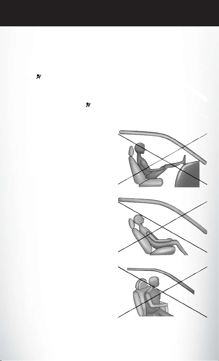
The OCS determines the front passenger’s most probable classification. If an occupant in the
front passenger seat isseatedimproperly, theoccupant may provide an output signalto the OCS
that is different from the occupant’s properly seated weight input, for example:
The Air Bag Warning Light in the instrument
panel
unable to classify the front passenger seat status. A malfunction in the OCS may affect the
operation of the air bag system.
If the Air Bag Warning Light
come on, or stays on after you start the vehicle,
or it comes on as you drive, take the vehicle to
an authorized dealer for service immediately.
The passenger seat assembly contains critical
OCS components that may affect the Passenger Advanced Front Air Bag inflation. In order
for the OCS to properly classify the seated
weight of a front seat passenger, the OCS
components must function as designed.
Do not make any modifications to the front
passenger seat components, assembly, or to
the seat cover. If the seat,trim cover,or cushion
needs service for any reason,takethevehicle to
your authorized dealer. Only FCA US LLC
approved seat accessories may be used.
The following requirements must be strictly
followed:
• Do not modify the front passenger seat as-
• Do not use prior or future model year seat
• Do not replace the seat cover or cushion
• Do not add a secondary seat cover or mat.
• At no time should any Supplemental Re-
will turn on whenever the OCS is
does not
sembly or components in any way.
covers or cushions not designated by FCA
US LLC for the specific model being repaired. Always use the correct seat cover
and cushion specified for the vehicle.
with an aftermarket seat cover or cushion.
straint System (SRS) component or SRS related component or fastener be modified or
replaced with any part except those which
are approved by FCA US LLC.
Not Seated Properly
Not Seated Properly
Not Seated Properly
Not Seated Properly
27
Page 30
GETTING STARTED
Supplemental Knee Air Bags
This vehicle is equipped with a Supplemental Driver Knee Air Bag mounted in the instrument
panel below the steering column and a Supplemental Passenger Knee Air Bag mounted in the
instrument panel below the glove compartment. The Supplemental Knee Air Bags provide
enhanced protection duringa frontal impactby working togetherwith the seatbelts, pretensioners, and Advanced Front Air Bags.
WARNING!
• Relying on the air bags alone could lead to more severe injuries in a collision. The air bags
work with your seat beltto restrain you properly.In somecollisions,theair bags won't deploy
at all. Always wear your seat belts even though you have air bags.
• Being too close to the steering wheel or instrument panel during Advanced Front Air Bag
deployment could cause serious injury, including death. Air bags need room to inflate.
Sit back, comfortably extending your arms to reachthe steering wheel or instrument panel.
• No objects should be placed over or near the air bag on the instrument panel or steering
wheel because any such objects could cause harm if the vehicle is in a collision severe
enough to cause the air bag to inflate.
Supplemental Side Air Bags
This vehicle is equipped with Supplemental Seat-Mounted Side Air Bags (SABs) located in the
outboard side of the front seats. The SABs are marked with a SRS AIRBAG or AIRBAG label
sewn into the outboard side of the seats.
This vehicle is equipped with Supplemental Side Air Bag Inflatable Curtains (SABICs) located
above the side windows. Thetrim covering the SABICs is labeledSRS AIRBAG or AIRBAG. The
SABICs may help reduce the risk of partial or complete ejection of vehicle occupants through
side windows in certain rollover or side impact events.
The SABICs and SABs (“Side Air Bags”) are designed to activate in certain side impacts and
certain rollover events. The Occupant Restraint Controller (“ORC”) determines whether the
deployment of the SideAir Bags in aparticular side impact orrolloverevent is appropriate, based
on the severity and type of collision. Vehicle damage by itself is not a good indicator of whether
or not Side Air Bags should have deployed.
28
Page 31

GETTING STARTED
WARNING!
• Side Air Bags need room to inflate. Do not lean against the door or window. Sit upright in
the center of the seat.
• Being too close to the Side Air Bags during deployment could cause you to be severely
injured or killed.
• Relying onthe Side Air Bagsalone could lead tomore severe injuries in acollision. The Side
Air Bags work with your seat belt to restrain you properly. In some collisions, Side Air Bags
won’t deploy at all. Always wear your seat belt even though you have Side Air Bags.
• This vehicle is equipped with left and right Supplemental Side Air Bag Inflatable Curtains
(SABICs). Do not stack luggageor other cargo up highenough to block the deploymentof
the SABICs. The trim covering above the side windows where the SABIC and its deployment path are located should remain free from any obstructions.
• This vehicle is equipped with SABICs. In order for the SABICs to work as intended, do not
install any accessory items in your vehicle which could alter the roof. Do not add an
aftermarket sunroof to your vehicle. Do not add roof racks that require permanent attachments (bolts or screws) for installation on the vehicle roof. Do not drill into the roof of the
vehicle for any reason.
• Do not use accessory seat covers or place objects between you and the Side Air Bags; the
performance could beadversely affected and/or objectscould be pushed into you, causing
serious injury.
Enhanced Accident Response System
In the event of an impact, if the communication network remains intact, and the power remains
intact, depending on the nature of the event, the ORC will determine whether to have the
Enhanced Accident Response System perform the following functions:
• Cut off fuel to the engine.
• Flash hazard lights aslong as the battery has power or until the hazard light button is pressed.
The hazard lights can be deactivated by pressing the hazard light button.
• Turn on the interior lights, which remain on as long as the battery has power.
• Unlock the power door locks.
Enhanced Accident Response System Reset Procedure
In order to reset the Enhanced Accident Response System functions after an event, the ignition
switch must be changed from ignitionSTART or ON/RUN to ignition OFF. Carefully check the
vehicle for fuel leaks in the engine compartment and on the ground near the engine compartment and fuel tank before resetting the system and starting the engine.
29
Page 32

GETTING STARTED
Air Bag Warning Light
The air bags must be ready to inflate for your protection in a collision. The Occupant Restraint
Controller (ORC) monitors the internal circuits and interconnecting wiring associated with air
bag system electrical components.
The ORC monitors the readiness of the electronic parts of the air bag system whenever the
ignition switch isin the START or ON/RUN position. If the ignition switch isin the OFFposition
or in the ACC position, the air bag system is not on and the air bags will not inflate.
The ORC turns on the Air Bag Warning Light in the instrument panel for approximately four to
eight seconds for a self-check when the ignition switch is first turned to the ON/RUN position.
After the self-check,the Air Bag Warning Light will turn off. If the ORC detects a malfunction in
any part ofthe system, it turnson the Air Bag WarningLight, either momentarily orcontinuously.
A single chime will sound to alert you if the light comes on again after initial startup.
If the Air Bag Warning Light in the instrument panel is not on during the four to eight seconds
when the ignition switch is first turned to the ON/RUN position, stays on, or turns on while
driving, have the vehicle serviced by an authorized service center immediately.
NOTE:
If the speedometer, tachometer, or any engine related gauges are not working, the Occupant
Restraint Controller (ORC) may also bedisabled. In this condition the air bagsmay not be ready
to inflate for your protection. Have an authorized dealer service the air bag system immediately.
Event Data Recorder (EDR)
This vehicle is equipped with an event data recorder (EDR). The main purpose of an EDR is to
record, in certain crash or near crash-like situations, such as an air bag deployment or hitting a
road obstacle, data that will assist in understanding how avehicle’s systems performed. The EDR
is designed to record data related to vehicle dynamics and safety systems for a short period of
time, typically 30 seconds or less. The EDR in this vehicle is designed to record such data as:
• How various systems in your vehicle were operating;
• Whether or not the driver and passenger safety belts were buckled/fastened;
• How far (if at all) the driver was depressing the accelerator and/or brake pedal; and,
• How fast the vehicle was traveling.
These data can help provide a better understanding of the circumstances in which crashes and
injuries occur.
30
Page 33

GETTING STARTED
NOTE:
EDR data are recorded by your vehicle only if a non-trivial crash situation occurs; no data are
recorded by theEDR under normal driving conditions and no personal data (e.g., name, gender,
age, and crash location) are recorded. However, other parties, such as law enforcement, could
combine the EDR data with the type of personally identifying data routinely acquired during a
crash investigation.
To read datarecorded by an EDR,special equipment isrequired, and access tothe vehicle or the
EDR is needed. In addition to the vehicle manufacturer, other parties, such as law enforcement,
that have the specialequipment,can read the information if theyhave access to the vehicleorthe
EDR.
CHILD RESTRAINTS
Children 12 years or youngershouldride properly buckled up in arearseat, if available. According
to crash statistics, children are safer when properly restrained in the rear seats rather than in the
front.
Every state in the United States and all Canadian provinces require that small children ride in
proper restraint systems. This is the law, and you can be prosecuted for ignoring it.
NOTE:
• For additional information, refer to www.Seatcheck.org or call:
1-866-732-8243
• Canadian residents should refer to Transport Canada’s website for additional information:
http://www.tc.gc.ca/eng/motorvehiclesafety/safedrivers-childsafety-index-53.htm
LATCH – Lower Anchors And Tethers For CHildren
• Your vehicle is equipped with the child restraint anchorage system called LATCH, which
stands for Lower Anchors and Tethers for CHildren.
• The second row seating postions, the third row right side outboard position and the third row
center position have lower anchors and top tether anchors.
• The third row center tether may alternately be used by a child restraint, installed with the
seatbelt, in the left side outboard position.
LATCH System Weight Limit
You may use the LATCH anchorage system until the combined weight of the child and the child
restraint is 65 lbs (29.5 kg). Use the seat belt and tether anchor instead of the LATCH system
once the combined weight is more than 65 lbs (29.5 kg).
31
Page 34

GETTING STARTED
Locating LATCH Anchorages
The lower anchorages areround bars that arefound at the rear ofthe seat cushion whereit meets
the seatback, below the anchorage symbols on the seatback. They are just visible when you lean
into the rear seat to install the child restraint. You will easily feel them if you run yourfinger along
the gap between the seatback and seat cushion.
2nd Row Lower Anchorages 2nd Row Lower Anchorages
32
3rd Row Lower Anchorages
Page 35

GETTING STARTED
Locating Tether Anchorages
There are tetherstrap anchorages located behind all second row seating positions. Thethird row
has a tether anchor on the 40% seat for the right outboard position and in the center of the 60%
seat for either the center or left outboard seating position. All tether anchorages are located on
the back of the seat, near the floor.
2nd Row Buckets Tether Anchorages 2nd Row 3 Across Tether Anchorages
3rd Row Tether Anchorages
33
Page 36

GETTING STARTED
Center Seat LATCH
This vehicle has 4 lower LATCH anchorages in the third row, rear seat. Anchorages A and B are
used for the right outboard position behind the front passenger (1). Anchorages C and D are
used for the center seating position (2). The left outboard position (3) does not have lower
anchorages. Do not install a child restraint using anchorages B and C. This is not a LATCH
position in your vehicle.
If a child restraint installed in the center position blocks the seat belt webbing or buckle for the
outboard position, do not use that outboard position. If a child seat in the center position blocks
the outboard LATCH anchors or seat belt, do not install a child seat in that outboard position.
3rd Row Center LATCH Anchorages
WARNING!
• Use anchorages C andDto install a LATCH-compatiblechildrestraintin the center seating
position (2). Do not install a LATCH-compatible child restraint using anchorages B and C.
This is not a LATCH-compatible position in your vehicle.
•
Never use the same lower anchorage to attach more than one child restraint. Please refer to
“Installing The LATCH-CompatibleChild Restraint System” fortypical installation instructions.
Installing The Child Restraint Using The LATCH Lower Anchors
Never “share” a LATCH anchorage with two or more child restraints.
1. Loosen the adjusters on the lower straps and on the tether strap of the child seat so that you
can more easily attach the hooks or connectors to the vehicle anchorages.
2. Attach the lower hooks or connectors of the child restraint to the lower anchorages in the
selected seating position.
3. If the child restraint has a tether strap, connect it to the top tether anchorage. See below for
directions to attach a tether anchor.
34
Page 37

GETTING STARTED
4. Tighten all of the straps as you push the child restraint rearward and downward into the seat.
Remove slack in the straps according to the child restraint “manufacturer’s instructions”.
5. Test that the childrestraint is installedtightly by pulling back and forth on the child seat at the
belt path. It should not move more than 1 inch (25.4 mm) in any direction.
Installing The Child Restraint Using The Vehicle Seat Belts
The seat belts in the passenger seating positions are equipped with a Switchable Automatic
Locking Retractor (ALR) that isdesigned to keep the lap portion of the seatbelt tight around the
child restraint. Any seat belt system will loosen with time, so check the belt occasionally, and pull
it tight if necessary.
Tether Weight Limit
Always use the tether anchor when using the seat belt to install a forward facing childrestraint, up
to the recommended weight limit of the child restraint.
To Install A Child Seat Using An ALR
1. Pull enough of the seat belt webbing from the retractor to pass it through the belt path of the
child restraint. Do not twist the belt webbing in the belt path.
2. Slide the latch plate into the buckle until you hear a “click.”
3. Pull on the webbing to make the lap portion tight against the child seat.
4. To lock theseatbelt, pull down on the shoulderpartof the belt until you havepulledall the seat
belt webbing out of the retractor. Then, allow the webbing to retract back into the retractor.
As the webbing retracts, you will hear a clicking sound. This means the seat belt is now in the
Automatic Locking mode.
5. Tryto pull the webbing outofthe retractor.Ifit is locked, you should notbe able to pull outany
webbing. If the retractor is not locked, repeat the last step.
6. Finally, pull up on any extra webbing to tighten the lap portion around the child restraintwhile
you push the child restraint rearward and downward into the vehicle seat.
If the child restraint has a top tether strap and the seating position has a top tether anchorage,
7.
connect the tether strapto the anchorage and tightenthe tether strap. See below fordirections to
attach a tether anchor.
8. Test that the child restraint is installed tightly by pulling back and forth on thechild seat at the
belt path. It should not move more than 1 inch (25.4 mm) in any direction.
Attaching The Top Tether Strap (With Either Lower Anchors Or Vehicle Seat Belt)
When installing a forward-facing child restraint, always secure the top tether strap, up to the
tether anchor weight limit, whether the child restraint is installed with the lower anchors or the
vehicle seat belt.
35
Page 38

GETTING STARTED
Tether Strap Attachment
1. Route the tetherstrap toprovide themostdirectpath for the strap between the anchorandthe
child seat.
2. If your vehicle is equipped with adjustable rear head restraints, raise the head restraint, and
where possible, route the tether strap under the head restraint and between the two posts.
If not possible, lower the head restraint and pass the tether strap around the outboard side of
the head restraint.
3. Attach the tether strap hook of the child restraint to the top tether anchorage and remove
slack in the tether strap according to the child restraint manufacturer’s instructions.
Third Row Tether Attachment
The tether anchorage found on the back of the 60% seat in the third row may be used by either
the left outboard or the center seating position. Only tether one child restraint to the tether
anchorage at a time.
To connect the tether strap hook to the tether anchorage for either seating position on the 60%
third row seat:
1. Route the tetherstrap toprovide themostdirectpath for the strap between the anchorandthe
child seat.
2.
If the car seat is in the center, raise or remove the center head restraint and route the tether strap
around the inboard (right) side of the head restraint support posts, as shown in the diagram.
3. Attach the tether strap hook of the child restraint to the top tether anchorage as shown in the
diagram.
4. Remove slack in the tether strap according to the child restraint manufacturer’s instructions.
Center Tether Attachment – 3rd Row
36
Outboard Tether Attachments – 3rd Row
Page 39

GETTING STARTED
WARNING!
Do not connect the tether strap for more than one child restraint to the tether anchorage on
the 60% seat in the third row. This anchorage is intended for one child restraint at a time.
NOTE:
If the folding, non-adjustable head restraint
interferes with the installation of the child restraint, the head restraint may be folded and
the child seat installed in front of it.
Child Restraint Installed In Front Of
Folded Head Restraint
WARNING!
Always make sure the head restraint is in its upright position when the seat is to be used by an
occupant who is not in a child restraint. Sitting in a seat with the head restraint in its lowered
position could result in serious injury or death in a collision.
WARNING!
• In a collision, an unrestrained child, even a tiny baby, can become a projectile inside the
vehicle. The force required to hold even an infant on your lap could become so great that
you could not hold the child, no matter how strong you are. The child and others could be
severely injured or killed. Any child riding in your vehicle should be in a proper restraint for
the child's size.
• Never place a rear-facing child restraint in front of an air bag. A deploying Passenger
Advanced Front Air Bag can cause death or serious injury to a child 12 years or younger,
including a child in a rear-facing child restraint.
• Only use a rear-facing child restraint in a vehicle with a rear seat.
• Improper installation of a child restraint to the LATCHanchorages can lead to failure of an
infant or child restraint. The child could be severely injured or killed. Follow the manufacturer’s directions exactly when installing an infant or child restraint.
• An incorrectly anchored tether strap could lead to increased head motion and possible
injury to the child. Use only the anchor positions directly behind the child seat to secure a
child restraint top tether strap.
• If yourvehicle is equippedwith a split rear seat, make surethe tether strap does not slip into
the opening between the seatbacks as you remove slack in the strap.
37
Page 40

GETTING STARTED
HEAD RESTRAINTS
Head restraints are designed to reduce the risk of injury by restricting head movement in the
event of a rear impact. Head restraints should be adjusted so that the top of the head restraint is
located above the top of your ear.
WARNING!
The head restraints for all occupants must be properly installed and adjusted prior to
operating the vehicle or occupying a seat. Head restraints shouldnever be adjusted while the
vehicle is in motion. Driving a vehicle withthe head restraints improperly adjusted or removed
could cause serious injury or death in the event of a collision.
Head Restraints — Front Seats
The front driver and passenger seats are equipped with four-way head restraints.
To raise the headrestraint,pull upward on thehead restraint. To lower thehead restraint, push the
adjustment button, located at the base of the head restraint, and push downward on the head
restraint. Front head restraints are also adjustable forward and rearward.
NOTE:
To remove the head restraint, raise it as far as it can go then push the release button and the
adjustment button at the base of each post while pulling the head restraint up. Seatback angle
may need tobe adjusted tofully remove the head restraint. To reinstall thehead restraint, put the
head restraint posts into the holes and push downward. Then adjust the head restraint to the
appropriate height.
WARNING!
• A loosehead restraint thrown forward in acollision or hard stop couldcause serious injury or
death to occupants of the vehicle. Always securely stow removed head restraints in a
location outside the occupant compartment.
• ALL the head restraints MUST be reinstalled in the vehicle to properly protect the
occupants. Follow the re-installation instructions above prior to operating the vehicle or
occupying a seat.
Head Restraints — Second Row
The second row outboard head restraintsare non-adjustable. Theremovable 8th passenger seat
(if equipped) has an adjustable head restraint.
38
Page 41

GETTING STARTED
Head Restraints — Third Row
The outboard head restraints can be manually folded forward for improved visibility while in
reverse. Pull the release strap to fold them forward.
NOTE:
• The head restraints must be raised manually when occupying the third row.
• Do not fold if there are passengers seated in the third row seats.
The head restraint in the center position can be raised and lowered for tether routing or height
adjustment. Refer to “Occupant Restraint Systems” in “Safety” in your Owner’s Manual on the
DVD for further information.
Power Folding Third Row Head Restraints — If Equipped
For improved visibility, the third row outboard head restraints can be folded using the Uconnect
System.
Press the “Controls” button located on the bottom of the Uconnect display.
Press the Head Restraint Fold button
NOTE:
•
The head restraints canbe folded downward using theHead Restraint button or usingthe manual
release strap. The head restraints must be raised manually when occupying the third row.
• Do not fold if there are passengers seated in the third row seats.
to power fold the third row head restraints.
FRONT SEATS
Manual Adjustment (Front Seats)
WARNING!
• Adjusting a seat while the vehicle is moving is dangerous. The sudden movement of the
seat could cause you to lose control. The seat belt might not be adjusted properly and you
could be injured. Adjust the seat only while the vehicle is parked.
• Do not ride with the seatback reclined so that the shoulder belt is no longer resting against
your chest. In a collision you could slide under the seat belt and be seriously or even fatally
injured. Use the recliner only when the vehicle is parked.
39
Page 42

GETTING STARTED
Manual Front Adjuster
Both front seats are adjustable forward or rearward. The manual seat adjustment handle is
located under the seat cushion at the front edge of each seat.
While sitting in the seat, pull up on the handle
and slide the seat forward or rearward. Release
the bar once you have reached the desired
position. Then, using body pressure, move forward and rearward on the seat to be sure that
the seat adjusters have latched.
Manual Seat Adjuster
WARNING!
• Adjusting a seat while driving may be dangerous. Movinga seat while drivingcould result in
loss of control which could cause a collision and serious injury or death.
• Seats should be adjusted before fastening the seat belts and while the vehicle is parked.
Serious injury or death could result from a poorly adjusted seat belt.
Manual Reclining Seats — If Equipped
For models equipped with manual seats, the recline lever is located on the outboard side of the
seat.
To recline, lean forward slightly, lift the lever,
then push back to the desired position and
release the lever. Lean forwardand lift the lever
to return the seatback to its normal position.
Using body pressure, lean forward and rearward on the seat to be sure the seatback has
latched.
Manual Recline Lever
40
Page 43

GETTING STARTED
WARNING!
Do not ride with the seatback reclined so that the shoulder belt is no longer resting against
your chest. In a collisionyou could slideunder the seat belt, which could resultin serious injury
or death.
Seat Height Adjustment
The driver’s seatheight can be raised or lowered by using a lever, located onthe outboard side of
the seat. Pump the leverupwardtoraise the seat height, or pumpthe lever downward to lower the
seat height.
Power Adjustment (Front Seats) — If Equipped
Some models may be equipped witheight-way
power seats for the driver and front passenger.
The power seat switches are located on the
outboard side of the seat. The switches control
the movement of the seat cushion and the
seatback.
Driver Power Seat Switches
1 — Seat Switch
2 — Seatback Switch
3 — Lumbar Switch
CAUTION!
Do not place any article under a power seat or impede its ability to move as it may cause
damage to the seat controls. Seat travel may become limited if movement is stopped by an
obstruction in the seat's path.
41
Page 44

GETTING STARTED
WARNING!
• Adjusting a seat while driving may be dangerous. Movinga seat while drivingcould result in
loss of control which could cause a collision and serious injury or death.
• Seats should be adjusted before fastening the seat belts and while the vehicle is parked.
Serious injury or death could result from a poorly adjusted seat belt.
• Do not ride with the seatback reclined so that the shoulder belt is no longer resting against
your chest. In a collision you could slide under the seat belt, which could result in serious
injury or death.
Adjusting The Seat Forward Or Rearward
The seat can be adjusted both forward and rearward. Push the seat switch forward or rearward.
The seat will move in the direction ofthe switch. Release theswitch when the desired positionhas
been reached.
Adjusting The Seat Up Or Down
The height of the seats can be adjusted up or down. Pull upward or push downward on the seat
switch, the seat will move in the direction of the switch. Release the switch when the desired
position has been reached.
Tilting The Seat Up Or Down
The angle of the seat cushion can be adjusted in four directions. Pull upward or push downward
on the front or rear of the seat switch, the front or rear of the seat cushion will move in the
direction of the switch. Release the switch when the desired position has been reached.
Reclining The Seatback
The angle of the seatback can be adjusted forward or rearward. Push the seatbackswitch forward
or rearward, the seat will move in the direction of the switch. Release the switch when the desired
position is reached.
CAUTION!
Do not place any article under a power seat or impede its ability to move as it may cause
damage to the seat controls. Seat travel may become limited if movement is stopped by an
obstruction in the seat's path.
42
Page 45

GETTING STARTED
WARNING!
• Adjusting a seat while driving may be dangerous. Movinga seat while drivingcould result in
loss of control which could cause a collision and serious injury or death.
• Seats should be adjusted before fastening the seat belts and while the vehicle is parked.
Serious injury or death could result from a poorly adjusted seat belt.
• Do not ride with the seatback reclined so that the shoulder belt is no longer resting against
your chest. In a collision you could slide under the seat belt, which could result in serious
injury or death.
Power Lumbar — If Equipped
Vehicles equipped with power driver or passenger seats may be equipped with power lumbar.
The power lumbar switch is located on the outboard side of the power seat. Push the switch
forward or rearward to increase or decrease the lumbar support. Push the switch upward or
downward to raise or lower the lumbar support.
Driver Memory Seat — If Equipped
The Memory Buttons 1 and 2on the driver's door panel can beprogrammed to recall thedriver's
seat, outside mirrors, and radio station preset settings. Your Remote Keyless Entry (RKE) Key
Fobs can also be programmedto recall the samepositions when the UNLOCK button is pushed.
Your vehicle may have been delivered with two
RKE Key Fobs, one RKE KeyFobcan be linked
to each of the memory positions.
Programming The Memory Feature
To create a new memory profile, perform the
following:
1. Cycle the vehicles ignition to the ON/RUN
position (do not start the engine).
2. Adjustall memory profile settings to desired
preferences (i.e., driver’s seat, outside mirrors and radio station presets).
3. Push and release the S (Set) button on the memory switch.
4. Within five seconds,push and release eitherof the memory buttons(1) or (2). The Instrument
Cluster Display will show which memory position has been set.
NOTE:
• Memory profiles can be set without the vehicle in PARK, but the vehicle must be in PARK to
recall a memory profile.
• To set a memory profile to your RKE Key Fob, refer to “Linking And Unlinking The Remote
Keyless Entry Key Fob To Memory” in this section.
Driver Memory Switch
43
Page 46

GETTING STARTED
Linking And Unlinking The Remote Keyless Entry Key Fob To Memory
Your RKE Key Fob can be programmed to recall oneoftwo pre-programmedmemory profiles by
pushing the UNLOCK button on the RKE Key Fob.
NOTE:
Before programming your RKE Key Fob you must select the “Personal Settings Linked to Key
Fob” feature through the Uconnect Settings. Refer to “Uconnect Settings” in “Multimedia” in
your Owner’s Manual on the DVD for further information.
To program your RKE Key Fob, perform the following:
1. Cycle the vehicle’s ignition to the OFF position.
2. Select a desired memory profile (1) or (2).
NOTE:
If a memory profile has not alreadybeenset, refer to "Programming The Memory Feature" in this
section for instructions on how to set a memory profile.
3. Once the profile has been recalled, push and release the SET (S) button on the memory
switch.
4. Push and release button (1) or (2) accordingly. “Memory Profile Set” (1 or 2) will display in the
instrument cluster.
5. Push and release the LOCK button on the RKE Key Fob within 10 seconds.
NOTE:
Your RKE KeyFobcan be unlinkedto your memorysettings by pushing the SET (S) button, and
within 10 seconds, followed by pushing the UNLOCK button on the RKE Key Fob.
Memory Position Recall
NOTE:
The vehicle mustbe in PARK to recall memory positions. If a recall is attemptedwhen the vehicle
is not in PARK, a message will be displayed in the Instrument Cluster Display.
To recall the memory settings for driverone,push MEMORY button 1 on the driver's dooror the
UNLOCK button on the RKE Key Fob linked to memory position 1.
To recall the memory setting for driver two, push MEMORY button 2 on thedriver's door or the
UNLOCK button on the RKE Key Fob linked to Memory Position 2.
A recall can be cancelled by pushing any of the MEMORY buttons on the driver's door during
a recall (S, 1, or 2). Whenarecall is cancelled, the driver's seatstopmoving. A delay of one second
will occur before another recall can be selected.
NOTE:
Pushing the mirror adjust switch will cancel the memory mirror recall.
44
Page 47

GETTING STARTED
Easy Entry/Exit Seat (Available With Memory Seat Only)
This feature provides automatic driver seat positioning toenhance driver mobilitywhen entering
and exiting the vehicle.
The distance the driver seat moves depends on where you have the driver seat positioned when
you cycle the vehicle’s ignition to the OFF position.
• When the ignition switch transitions to the LOCK position, the driver seat will move about
2.4 inches (60 mm) rearward if the driver seat position is greater than or equal to 2.7 inches
(67.7 mm) forward of the rear stop. The seat will return to its previously set position when the
ignition switch transtions out of the LOCK position.
• When the ignition switch transitions out of the LOCK position, the driver seat will move to a
position 0.3 inches (7.7 mm) forward of the rear stop if the driver seat position is between
0.9 – 2.7 inches (22.7 – 67.7 mm) forward of the rear stop. The seat will return to its previously
set position when the ignition switch transitions out of the LOCK position.
The Easy Entry/Easy Exit feature is disabled when the driver seat position is less than 0.9 inches
•
(22.7 mm) forward of therear stop. At this position, thereis no benefit tothe driver by movingthe
seat for Easy Exit or Easy Entry.
Each stored memory setting will have an associated Easy Entry and Easy Exit Position.
NOTE:
The Easy Entry/Easy Exit feature can be enabledor disabled through the programmable features
in the Instrument Cluster Display. For further information refer to “Display” in “Getting To Know
Your Instrument Panel” in your Owner’s Manual on the DVD.
REAR SEATS
Manual Adjustment (Rear Seats)
Manual Adjustment Precautions
WARNING!
• Adjusting a seat while the vehicle is moving is dangerous. The sudden movement of the
seat could cause you to lose control. The seat belt might not be adjusted properly and you
could be injured. Adjust the seat only while the vehicle is parked.
• Do not ride with the seatback reclined so that the shoulder belt is no longer resting against
your chest. In a collision you could slide under the seat belt and be seriously or even fatally
injured. Use the recliner only when the vehicle is parked.
45
Page 48

GETTING STARTED
Manual Recline
To recline, lean forward slightly, lift the lever,
then push back to the desired position and
release the lever. Lean forwardand lift the lever
to return the seatback to its normal position.
Using body pressure, lean forward and rearward on the seat to be sure the seatback has
latched.
Recline Lever
WARNING!
Do not ride with the seatback reclined so that the shoulder belt is no longer resting against
your chest. In a collision you could slideunder the seat belt, which could resultin serious injury
or death.
Fold-Flat
To fold the seat, lift the recliner lever to the full upward position and push the seatback forward
until it rests on the seat cushion.
NOTE:
• The seatback may lock into the foldflat position. Use the recline lever to unlock the seatback.
• When returning the seat to the original position, the headrest must be folded back to the
original position.
46
Page 49

GETTING STARTED
Easy Entry
Easy Tilt Seat — With Or Without Child Seat Installed
The 2nd row seats can be tilted forward for easy entry into the third row with or without a child
seat installed.
1. Located in the seatback of the second row
seat is a handle thatprovideseasier access to
the third row by tilting the seat forward.
2. To put the seat back into original position,
just pull back on the seatback and lock the
seat into position.
Easy Tilt Seat Handle
WARNING!
Do not use this feature with a child in seat. Serious injury or death my occur.
Easy Entry — With The Seat Folded Flat
The seats can be folded and tiltedformore accessibility for passengers to enterandexit the third row.
1. Without a child seat installed, you can fold the seat by pulling the recliner handle on the
bottom part of theseat.Before pulling the recliner lever, make sure the arm restsarefolded up.
2. Pull thestrapon the back ofthe seat and the
seat will tilt forward.
3. To put it back into position, pull back on the
folded seat and make sure that it locks into
position. Then pull the seatback toward the
back and fold down the arm rests.
Pull Strap
47
Page 50

GETTING STARTED
Exit For 3rd Row Passengers
Forpassengers seated in the third row,thereis a pull strap located ontheoutboard side of the seat
near the bottom of the seat back. Third row passengers can pull on the strap and push the seat
forward for folding the seatback down and tilting the seat to the floor.
NOTE:
This process is for when there is no child seat installed. Use the easy entry lever if a child seat is
installed.
Stow 'n Go Seating
On vehicles equippedwith Stow 'n Go seating, the secondand third row seatscan be folded into
the floor for convenient storage.
Stow ‘n Go Assist — If Equipped
On vehicles equipped with the Stow ‘n Go Assist feature, the front seat will move forward
automatically to a location that will allow the second row Stow ‘n Go seat movement, without
interference by the frontseat. After the second rowStow ‘n Go seatmovement is completed, the
front seat will automatically move backtothe previous location once the Stow‘nGo Assist button
is pushed again.
The Stow ‘n Go Assist feature is available to both the front driver and passenger power seats.
WARNING!
During power seat operation, personal injury or cargo damage may occur. Ensure the front
seat is not occupied and the seat travel path is clear.
A one-touch Stow ‘n Go Assist button is located on the B-pillar trim panel, just in front of the
power sliding door.
Using the Stow ‘n Go Assist Feature
NOTE:
• The button is only functional when the
power sliding door is open and the vehicle is
in PARK. If the door is not open or the
vehicle is not in PARK when the button is
pushed, the front seat will not move and a
message will be displayed in Instrument
Cluster Display.
• If the power sliding door is closing when the
button is pushed, the front seat will not
move and a message will be displayed in the Instrument Cluster Display.
Stow ‘n Go Assist button
48
Page 51

GETTING STARTED
1. Push andrelease the Stow ‘n Go Assist button. The front seatcushion and seat back will move
as necessary to a location that will allow space for the second row Stow ‘n Go seat movement.
2. Perform the second row Stow ‘n Go seat movement. Refer to “Second Row Stow ‘n Go” for
further information.
3. Push and release the Stow ‘n GoAssist button a second time. The front seat cushion and seat
back will return to the original starting location.
NOTE:
• To abort seat operation while seat is in motion, push the Stow n’ Go Assist button, or push the
front power seat button to stop the seat movement. Pushing the Stow ‘n Go Assist button
again will return the front seat to the original starting location.
• The Stow ‘n Go Assist system includes obstacle detection. When the system detects an
obstacle, the seat will stop, reverse direction, and return to the previous location. A message
will be displayed in the instrument cluster indicating that an obstacle has been detected.
• If the front seat is already in a location that will allow space for Stow ‘n Go of the second row
seat, the front seat will not move and a message will be displayed in the instrument cluster.
• If calibration of the front seat is lost, the seat will automatically re-calibrate when the Stow ‘n
Go Assist button is pushed.Thismay result in the seat cushionmovingforward and downward,
before moving to the location that will allow space for the second row Stow ‘n Go seat
movement.
Second Row Stow 'n Go
For Manual Seats: To stow the seat in thefloor, move the frontseat all the wayforward using the
manual seat adjustment bar. Move the seat back all the way forward using the recliner handle
located on the outboard side of the cushion. Move the seat height to at least mid position using
the height adjuster handle in the outboard side of the cushion.
For Power Seats: Push the Stow ‘n Go Assist button located on the B pillar trim (if equipped.)
Refer to "Stow 'n Go Assist - If Equipped" in this section for instructions.
1. To access the storage bin, place the lock rod in the locked position.
NOTE:
• Push the lock rod inward for the locked position.
• Pull outward on the lock rod for the unlocked position.
• For information on storage bin function with the seats rearward refer to “Internal Equipment” in “Getting To Know Your Vehicle” in the Owner’s Manual on the DVD for further
information.
2. Pull the latch located near the second row seat to open the floor panel.
3. Pull the floor panel and position it toward the front seats while folding the top half down and
rest it against the front seats.
4. Stow the seat by grabbing the strap on the lower part of the backseat and guide the seat into
the tub.
49
Page 52

GETTING STARTED
5. Push down on the seat back to lock the seat in the tub.
6. Close the floor by pulling the floor panel backwards by the bottom corner edge of the panel.
7. Push down on floor panel to lock into place.
8. Readjust the front seat as needed.
Refer to “Stow ‘n Go” in “Getting to Know Your Vehicle” in the Owner’s Manual on the DVD for
additional information.
CAUTION!
• The storage bin cover must be locked and flat to avoid damage from contact with the front
seat tracks, which have minimal clearance to the cover.
• Do notsit on the secondrow seat when itis in the stowed position with theseatback upright
otherwise damage to the seat may occur.
WARNING!
In a collision, serious injury could result if the seat storage bin covers are not properly latched:
• Do not drive the vehicle with the storage bin covers open.
• Keep the storage bin covers closed and latched while the vehicle is in motion.
• Do not use a storage bin latch as a tie down.
To Unstow Second Row Seats
For Manual Seats: To unstow the seat from the floor, move the front seat all the way forward
using the manual seat adjustment bar.
For Power Seats: Push the Stow ‘n Go Assist button located on the B pillar trim (if equipped).
Refer to "Stow 'n Go Assist - If Equipped" in this section for instructions.
1. To access the storage bin, place the lock rod in the locked position.
NOTE:
• Push the lock rod inward for the locked position.
• Pull outward on the lock rod for the unlocked position.
2. Pull the latch located near the second row seat to open the floor panel.
3. Pull the floor panel and position it toward the front seats while folding the top half down and
rest it against the front seats.
4. Pull the strap located on the seat and pull the seat out of the storage bin. Push the seat
rearward making sure that it locks into the floor. Fold the seatback into the upright position
and pull the headrest up.
50
Page 53

GETTING STARTED
NOTE:
The seatback may be locked, if it is, it will be necessary to use the recliner handle to unlock the
back before folding into the upright position.
5. To position the floor panel back into its original state, grab the bottom corner and extend it
outward.
6. Lay the floor panel flat and push down until it clicks into position. Replace the floor mat as
needed.
7. Readjust the front seat as needed.
Refer to “Stow ‘n Go” in “Getting to Know Your Vehicle” in the Owner’s Manual on the DVD for
additional information.
WARNING!
• In a collision, you or others in your vehicle could be injured if seats are not properly latched
to their floor attachments. Always be sure the seats are fully latched.
• Sitting in a seat with the head restraintin its lowered position could result in seriousinjury or
death in a collision. Always make sure the headrestraints are in their upright positions when
the seat is to be occupied.
Second Row Removable 8th Seat — If Equipped
While the 8th seat does not stow inthe floor, it is foldable and removable for added cargo space.
The release strap is located on the front of the seat, near the floor. To remove the seat, pull the
release strap torelease the rear latches.The seat assemblycan now beremoved from the vehicle
by moving it in a rearward direction from the detent positions in the floor.
NOTE:
Seat can be removed easier with one outboard seat stowed in the load floor.
To reinstall the seat, align the seat into the detent positions on the floor. Tilt seat rearward to lock
the seat back into its original position.
WARNING!
If not properly latched, the seat could become loose. Personal injuries could result.
Manually Folding Third Row Seats — If Equipped
1. Lower the center head restraint down to the seatback by pushing the button on the guideand
pushing the head restraint down.
2. Pull release strap marked “1” to release the anchors.
3. Pull release strap marked “2” and tumble the seat rearward into the storage bin.
51
Page 54

GETTING STARTED
To Unfold Third Row Seats
1. Pull up on the assist strapto lift the seat out of the storage bin and push the seat forward until
the anchors latch.
2. Pulling strap “2” releases the seatback to return to its full upright position.
3. Raise the head restraint to its upright position.
WARNING!
• In a collision, you or others in your vehicle could be injured if seats are not properly latched
to their floor attachments. Always be sure the seats are fully latched.
• Sitting in a seat with the head restraintin its loweredposition could result in serious injury or
death in a collision. Always make sure the headrestraints are in their upright positions when
the seat is to be occupied.
Power Adjustment (Rear Seats) — If Equipped
WARNING!
• Adjusting a seat while driving may be dangerous. Movinga seat while drivingcould result in
loss of control which could cause a collision and serious injury or death.
• Seats should be adjusted before fastening the seat belts and while the vehicle is parked.
Serious injury or death could result from a poorly adjusted seat belt.
• Do not ride with the seatback reclined so that the shoulder belt is no longer resting against
your chest. In a collision you could slide under the seat belt, which could result in serious
injury or death.
CAUTION!
Do not place any article under a power seat or impede its ability to move as it may cause
damage to the seat controls. Seat travel may become limited if movement is stopped by an
obstruction in the seat's path.
Third Row Power Recline — If Equipped
The power recline feature, located on the trim panel next to the seat, adjusts the seatback angle
forward/rearward for occupant comfort.
Reclining The Seatback
The angle of the seatback can be adjusted forward or rearward. Push and hold the forward or
rearward button, the seat will move in the direction of the button push. Releasethe button when
the desired position is reached.
52
Page 55

GETTING STARTED
Third Row Power Stow ‘n Go Seat — If Equipped
A one-touch power folding seat switch is located in the right rear trim panel as part of a switch
bank.
NOTE:
• The outer head restraints will lower automatically as necessary when the power seat begins to
move.
• The center head restraint raises and lowers manually but will not lower automatically.
• The headrestraintcan also be lowered manuallyusing the pull strap located atthe back off the
seat. Refer to "Head Restraints - Third Row" in "Head Restraints" for further information.
The switch is only functional when the liftgate is open and the vehicle is in PARK.
The rear switch bank allowsmultiplepower folding and unfolding positionsforthe third row seats.
Left and right third row seats can be folded individually or together.The third row power folding
seat adjusts to the following positions using the switch bank located on the left rear trim panel:
To move the selected seat(s) to the Normal
(seated) position, push and release the Normal
button. The seat will automatically stop when
the Normal position is reached.
To move the selected seat(s) to the stow position, push and release the Stow button. The seat
will automatically stop when the Stow position is
reached.
To move the selected seat(s) back in the forward or reverse direction, push and hold the
Fold forward or rearward button. Release the
button when the desired position is reached.
NOTE:
• Disconnect the center shoulder belt from
the small buckle before attempting to fold/
stow the power third row seats.
• To abortseat operation while seat is in motion,push a different seat position selector switchto
stop the seat. Once the seat stops moving, then the desired position can be selected.
• The third row power seat system includes obstacle detection. When the system detects an
obstacle, the motors will stop and reverse direction. Should this occur, remove the obstacle
before pushing the button again.
Rear Panel Power Switch Bank
1 — Open To Normal
2 — Stow
3 — Fold Forward/Rearward
4 — Right/Left Seats/Both Seats
53
Page 56

GETTING STARTED
HEATED/VENTILATED SEATS
Front Heated Seats — If Equipped
The front heated seats control buttons are located within the climate or controls screen of the
touchscreen.
You can choose from HI, LO or OFF heat settings. The indicator lightsineach switch indicate the
level of heat in use. Two indicator lights will illuminate for HI, one for LO and none for OFF.
• Press the heated seat button
• Press the heated seat button
• Press the heated seat button
If the HI-level setting is selected, the system will automatically switch to LO-level after approximately 60 minutes of continuous operation. At that time, the display will change from HI to LO,
indicating the change. The LO-level setting will turn OFF automatically after approximately
45 minutes.
NOTE:
• Once a heat setting is selected, heat will be felt within two to five minutes.
• The engine must be running for the heated seats to operate.
Vehicles Equipped With Remote Start
On models that are equipped withremotestart,the heated seats can be programmed to come on
during a remote start.
This feature can be programmed through the Uconnect system. Refer to “Uconnect Settings” in
“Multimedia” in the Owner's Manual on the DVD.
once to turn the HI setting ON.
a second time to turn the LO setting ON.
a third time to turn the heating elements OFF.
WARNING!
• Persons who are unable to feel pain to the skin because of advanced age, chronic illness,
diabetes, spinal cord injury, medication, alcohol use, exhaustion or other physical condition
must exercise care whenusing the seat heater. It maycause burns even atlow temperatures,
especially if used for long periods of time
•
Do not place anything on the seat or seatback that insulates against heat, such as a blanket or
cushion. This may cause the seat heater to overheat. Sitting in a seat that has been overheated
could cause serious burns due to the increased surface temperature of the seat.
54
Page 57

GETTING STARTED
Rear Heated Seats — If Equipped
On some models, the second row seats are equipped with heaters. There are two heated seat
switches that allow the second row passengers to operate the seats independently. The heated
seat switches are located on the sliding side door handle trim panels.
You can choose from HI, LO or OFF heat
settings. Amber indicator lights in each switch
indicate the level of heat in use. Two indicator
lights will illuminate for HI, one for LO and
none for OFF.
Push the switch onceto select HI-level heating.
Push the switch a second time to select LOlevel heating. Push the switch a third time to
shut the heating elements OFF.
NOTE:
Once a heat setting is selected, heat will be felt
within two to five minutes.
When the HI-level setting isselected,the heater will provide a boosted heatlevelduring the initial
stages of operation.Then, the heat output will drop to the normal HI-level.If the HI-level setting
is selected, the system will automatically switch to LO-level after approximately 60 minutes of
continuous operation. Atthat time, the displaywill change fromHI to LO,indicating the change.
The LO-level setting will turn OFF automatically after approximately 45 minutes.
Second Row Heated Seat Switch
Ventilated Seats — If Equipped
Located in the first row seat cushions are small fans that draw the air from the passenger compartment and move air through fine perforations in the seat cover to help keep the driver and front
passenger cooler in higher ambient temperatures. The fans operate at two speeds, HI and LO.
The front ventilated seats control buttons are located withinthe climate or controls screen ofthe
touchscreen.
• Press the ventilated seat button
• Press the ventilated seat button
• Press the ventilated seat button
NOTE:
The engine must be running for the ventilated seats to operate.
Vehicles Equipped With Remote Start
On models that are equipped with remote start, the ventilated seats can be programed to come
on during a remote start.
This feature can be programmed through the Uconnect system. Refer to “Uconnect Settings” in
“Multimedia” in the Owner's Manual on the DVD.
once to choose HI.
a second time to choose LO.
a third time to turn the ventilated seat OFF.
55
Page 58

GETTING STARTED
STEERING WHEEL
Tilt/Telescoping Steering Column
This feature allows you to tilt the steering column upward or downward. It also allows you to
lengthen or shorten the steering column. The tilt/telescoping lever is located left of the steering
wheel at the end of the steering column.
To unlock the steering column, push the lever
downward (toward the floor). To tilt the steering column, move thesteering wheel upward or
downward as desired. To lengthen or shorten
the steering column, pull the steering wheel
outward or push it inward as desired.To lock the
steering column in position, push the lever upward until fully engaged.
Tilt/Telescoping Lever
WARNING!
Do not adjust the steering column while driving. Adjusting the steering column while driving
or driving with the steering column unlocked, could cause the driver to lose control of the
vehicle. Failure to follow this warning may result in serious injury or death.
56
Page 59

GETTING STARTED
Heated Steering Wheel
The steering wheel contains a heating element that helps warm your hands in cold weather. The
heated steering wheel has only one temperature setting. Once the heated steering wheel has
been turned on it can operatefor up toapproximately 120 minutes before automatically shutting
off. The heated steering wheel can shut off early or may not turn on when the steering wheel is
already warm.
The heated steering wheel control button is located within the Uconnect controls screen.
• Press the heated steering wheel button
• Press the heated steering wheel button
NOTE:
The engine must be running for the heated steering wheel to operate.
Vehicles Equipped With Remote Start
On models that are equipped with remote start, the heated steering wheel can be programedto
come on during a remote start. Refer to“Uconnect Settings” in “Multimedia” in your Owner’s
Manual on the DVD for further information.
• Persons who are unable to feel pain to the skin because of advanced age, chronic illness,
diabetes, spinal cord injury, medication, alcohol use, exhaustion, or other physical conditions must exercise care when using the steering wheel heater. It may cause burns even at
low temperatures, especially if used for long periods.
• Do notplace anything on thesteering wheel that insulates against heat, suchas a blanket or
steering wheel coversof any type andmaterial. This may cause the steering wheel heater to
overheat.
once to turn the heating element ON.
a second time to turn the heating element OFF.
WARNING!
57
Page 60

OPERATING YOUR VEHICLE
ENGINE BREAK-IN RECOMMENDATIONS
3.6L Engine Break-In
For vehicles equipped with the 3.6L, use the following engine break-in recommendations:
A long break-in period is not required for the drivetrain (engine, transmission, clutch, and rear
axle) in your new vehicle.
Drive moderately during the first 300 miles (500 km). After the initial 60miles (100 km), speeds
up to 50 or 55 mph (80 or 90 km/h) are desirable.
While cruising, brief full-throttle acceleration withinthe limits oflocal traffic laws contributes to a
good break-in. However, wide-open throttle acceleration in low gear can be detrimental and
should be avoided.
The engine oil, transmission fluid, and axle lubricant installed at the factory is high-quality and
energy-conserving. Oil, fluid, and lubricant changes should be consistent with anticipated
climate and conditions underwhich vehicle operations willoccur. For the recommended viscosity
and quality grades, refer to “Maintenance Procedures” in “Maintaining Your Vehicle”.
CAUTION!
Never use Non-Detergent Oil or Straight Mineral Oil in the engine or damage may result.
NOTE:
A new engine may consumesomeoil during its first fewthousandmiles (kilometers) of operation.
This should be considered a normal part of the break-in and not interpreted as an indication of
difficulty. Please checkyour oil level with theengine oil indicator oftenduring the break in period.
Add oil as required.
58
Page 61

OPERATING YOUR VEHICLE
HEADLIGHT SWITCH
The headlight switch is located on the left side of the instrument panel. The switch controls the
operation of the headlights, parking lights, instrument panel lights, interior lights and the fog lights.
Rotate the headlight switch clockwise to the
second detent for parking light and instrument
panel light operation. Rotate the headlight
switch to thethird detent for headlight,parking
light and instrument panel operation.
Automatic Headlights
This system automatically turns your headlights
on or off based on ambient light levels. To turn
the system on, turn the headlight switch to the
extreme clockwise positionaligning the indicator
with the AUTO on the headlight switch. When
the system is on, the Headlight Time Delay feature is also on. This means your headlights will
stay on for up to 90 seconds after you turn the
ignition switch OFF. To turn the Automatic System off, turn the headlight switch counterclockwise to the O (OFF) position.
NOTE:
The engine must be running before the headlights will come on in the Automatic mode.
1 — Rotate Headlight Switch
2 — Ambient Dimmer Control
3 — Instrument Panel Dimmer
4 — Fog Lamps Button
Headlight Switch
Automatic High Beam — If Equipped
The Automatic High Beam system provides increased forward lighting at night by automating
high beam control through the use of a digital camera mounted on the windshield. This camera
detects vehicle specific light and automatically switches from high beams to low beams until the
approaching vehicle is out of view.
NOTE:
Broken, muddy or obstructed headlights and taillights of vehicles in the field of view will cause
headlights to remain on longer (closer to the vehicle). Also, dirt, film and other obstructions on
the windshield or camera lens will cause the system to function improperly.
59
Page 62

OPERATING YOUR VEHICLE
To Activate
1. Select “Automatic High Beams — ON” through the Uconnect system. Refer to "Uconnect
Settings” in “Multimedia” in your Owner’s Manual on the DVD for further information.
2. Rotate the headlight switch counterclockwise to the AUTO (A) position.
3. Push the multifunctionleveraway from you to switch theheadlightsto the high beam position.
Refer to “Multifunction Lever” in this section for further information.
NOTE:
This system will not activate until the vehicle is at, or above, 25 mph (40 km/h).
To Deactivate
Perform either of the following steps to deactivate the Automatic High Beam system.
1. Select “Automatic High Beams — OFF” through the Uconnect System. Refer to “Uconnect
Settings” in “Multimedia” in your Owner’s Manual on the DVD for further information.
2. Pull themultifunction lever toward you to switch the headlightsfrom the high beam to the low
beam position.
3. Rotate the headlight switch clockwise from the AUTO to the on position.
Instrument Panel Dimmer Control
The instrument panel dimmer control ispart of theheadlight switch andis located onthe driver’s
side of the instrument panel.
With the parking lights or headlights on, rotating the instrument panel dimmer control upward
will increase the brightness of the instrument panel lights.
Ambient Light Control — If Equipped
Rotate the ambient dimmer control upward or downward to increase or decrease the brightness
of the ambient light located in the overhead console, door handle lights, under I/P lights, door
map pocket lights, and cubby bin lights.
Interior Lighting Off
Rotate the right (instrument panel) dimmer control to the off position (extreme bottom). The
interior lights will remain off when the doors or liftgate are open.
Parade Mode (Daytime Brightness Feature)
Rotate the instrument panel dimmer control upward to the first detent. This feature brightens all
text displays such asthe odometer, Instrument Cluster Display,and radio when the positionlights
or headlights are on.
60
Page 63

OPERATING YOUR VEHICLE
MULTIFUNCTION LEVER
The multifunction lever is located on the left
side of the steering column. The multifunction
lever controls the turn signals, headlight beams
and flash-to-pass functions.
Turn Signals
Move the multifunction lever up or down and
the arrows on each side of the instrument cluster flash to show proper operation of the front
and rear turn signal lights.
NOTE:
If either light remains on and does not flash, or
there is a very fast flash rate, check for a defective outside light bulb. If an indicator fails to light
when the lever is moved, it would suggest that the indicator bulb is defective.
Turn Signal Warning
If the vehicle electronics sense that the vehicle has traveled at over 18 mph (29 km/h) for about
1 mile (1.6km) with the turnsignals on, a chimewill sound and a message will display in the cluster
to alert the driver.
Lane Change Assist — If Equipped
Tap the lever up or down once, without moving beyond the detent, and the turn signal (right or
left) will flash three times then automatically turn off.
Multifunction Lever
High/Low Beam Switch
When the headlights are turned on, pushing the multifunction lever toward the instrument panel
will switch from low beams to high beams. Pulling back to the neutral position returns the
headlights to the low beam operation.
61
Page 64

OPERATING YOUR VEHICLE
WINDSHIELD WIPER AND WASHERS
The wipers and washers are operated by a switch within the wiper lever. Rotate the end of the
wiper lever to select the desired wiper speed.
NOTE:
Always remove any buildup of snow that prevents the windshield wiper blades from returning to the off position. If the windshield wiper
switch is turned off and the blades cannot return to the off position, damage to the wiper
motor may occur.
Washer And Wiper Controls
WARNING!
Sudden loss of visibility through the windshield could lead to a collision. You might not see
other vehicles or other obstacles. To avoid sudden icing of the windshield during freezing
weather, warm the windshield with the defroster before and during windshield washer use.
Intermittent Wiper System
Use the intermittent wiper when weather conditions make a single wiping cycle with a variable
pause between cyclesdesirable. Rotate the endof the wiper lever to the firstdetent position, and
then turn the end of the lever to select the desired delay interval. There are four delay settings,
which allow you to regulate the wipe interval from a minimum of one cycle every second to a
maximum of approximately 36 seconds between cycles. The delay intervals will double in
duration when the vehicle speed is 10 mph (16 km/h) or less.
Windshield Wiper Operation
Rotate the end ofthe lever upward, to thefirst detent past the intermittentsettings for low-speed
wiper operation. Rotate the end of the lever upward to the second detent past the intermittent
settings for high-speed wiper operation.
Windshield Washers
To use the Washer, pull the lever rearward toward you and holdwhile spray is desired. If the lever
is pulled while on the intermittent setting, the wipers will turn on and operate for several wipe
cycles after the lever is released, and then resume the intermittent interval previously selected. If
the lever is pulled while the wipers are in the off position, the wipers will operate several wipe
cycles, then turn off.
62
Page 65

OPERATING YOUR VEHICLE
Mist Feature
Use the Mist feature when weather conditions make occasional usage of the wipers necessary.
Push the lever upward to the Mist position and release for a single wiping cycle.
NOTE:
The mist feature doesnot activate the washer pump;therefore,no washer fluid willbe sprayed on
the windshield. The wash functionmustbe used in order tospraythe windshield with washer fluid.
Rear Wiper And Washer
Rear Windshield Wiper Operation
Rotate the windshield wiper lever center ringupwardstooperatethe rear window wiper as follows:
• In intermittent mode when the front window wiper is not operating.
• In continuous mode with reverse engaged.
With the windshield wipers on and reverse gear engaged, rear window wiping will be continuous
in the same way.
Rear Windshield Washer Operation
Pushing the windshield wiper leverforwardactivates the rear window washer. Keep the windshield
wiper lever pushed for more than quarter a second to activate the rear window wiper as well.
Releasing the windshield wiper lever will activatethe smart washing function, as described forthe
windshield wipers.
The function stops when the windshield wiper lever is released.
Rain Sensing Wipers — If Equipped
This feature senses moisture on the windshield and automatically activates the wipers for the
driver.This feature is especially useful forroadsplash or overspray from thewindshieldwashers of
the vehicle ahead. Rotate the end of the multifunction lever toone of the four intermittent wiper
sensitivity settings to activate this feature.
The sensitivity of the system is adjustable from the multifunction lever. Wipersensitivity position
3 has been calibrated for best overall wiping sensitivity. If the operator desires more wiping
sensitivity, they may select sensitivity positions 4. If the operator desires less wiping sensitivity,
they may select sensitivitypositions 2 or 1. Placethemultifunction lever in the OFFposition when
not using the system.
NOTE:
• The Rain Sensing feature will not operate when the wiper speed is in the low or high position.
• The Rain Sensing feature may not function properly when ice or dried saltwater is present on
the windshield.
• Use of Rain-X or products containing wax or silicone may reduce rain sensor performance.
•
The Rain Sensing feature can be turned on and off through the Uconnect System. Refer to
“Uconnect Settings” in “Multimedia” in theOwner’s Manual on the DVD forfurther information.
63
Page 66

OPERATING YOUR VEHICLE
The Rain Sensingsystem has protective features forthe wiper blades and arms. It will notoperate
under the following conditions:
• Low Temperature Wipe Inhibit — The Rain Sensing feature will not operate when the
ignition is first switched ON,andthe vehicle is stationary, and the outside temperature is below
32°F (0°C), unless the wiper control on the multifunction lever is moved, the vehicle speed
becomes greater than 0 mph (0 km/h), or the outside temperature rises above freezing.
• Neutral Wipe Inhibit — The Rain Sensing feature will not operate when the ignition is ON,
and the transmission gear selector is in the NEUTRAL position, and the vehicle speed is less
than 3 mph (5 km/h), unless the wiper control on the multifunction lever is moved, thevehicle
speed is greater than 3 mph (5 km/h), or the gear selector is moved out of the NEUTRAL
position.
• Remote Start Mode Inhibit — On vehicles equipped with Remote Starting system, Rain
Sensing wipers are not operational when the vehicle is in the remote start mode. Once the
operator is in the vehicle and has placed the ignition switch in the RUN position, rain sensing
wiper operation can resume, if it hasbeenselected, and no other inhibit conditions(mentioned
previously) exist.
SPEED CONTROL
When engaged, theSpeed Control takes overaccelerator operations at speeds greater than 25mph
(40 km/h).
The Speed Control buttons are located on the right side of the steering wheel.
NOTE:
In order to ensure proper operation, the Speed
Control System has been designed to shut
down if multiple Speed Control functions are
operated at the same time. If this occurs, the
Speed Control System can be reactivated by
pushing the Speed Control ON/OFF button
and resetting the desired vehicle set speed.
To Activate
Push the ON/OFF button to activate the
Speed Control. The Cruise Indicator Light in
the Instrument Cluster Display will illuminate.
To turn the system off, push the ON/OFF
button a second time. The Cruise Indicator
Light will turnoff. The system should beturned
off when not in use.
64
Speed Control Switches
1 — Push Cancel
2 — Push Set+/Accel
3 — Push Resume
4 — Push On/Off
5 — Push Set-/Decel
Page 67

OPERATING YOUR VEHICLE
WARNING!
Leaving the Speed Control system onwhen not in use isdangerous.You could accidentallyset
the system orcause it to gofaster than you want.You could losecontrol and have anaccident.
Always leave the system OFF when you are not using it.
To Set A Desired Speed
Turn the Speed Control ON.
NOTE:
The vehicle should be travelingat asteadyspeed and on level ground before pushing the SET (+)
or SET (-) button.
When the vehicle hasreachedthe desired speed, push theSET(+) or SET (-) buttonand release.
Release the accelerator and the vehicle will operate at the selected speed.
To Vary The Speed Setting
To Increase Speed
When the Speed Control is set, you can increase speed by pushing the SET + button.
The driver’s preferred units can be selected through the Uconnect system if equipped. The
speed increment shown is dependant on the chosen speed unit of U.S. (mph) or Metric (km/h):
U.S. Speed (mph)
• Pushing the SET+button once will result in a 1mphincreasein set speed. Each subsequent tap
of the button results in an increase of 1 mph.
• If the button is continually pushed, the set speed will continue to increase until the button is
released, then the new set speed will be established.
Metric Speed (km/h)
• Pushing the SET + button once will result in a 1 km/h increase in set speed. Each subsequent
tap of the button results in an increase of 1 km/h.
• If the button is continually pushed, the set speed will continue to increase until the button is
released, then the new set speed will be established.
To Decrease Speed
When the Speed Control is set, you can decrease speed by pushing the SET - button.
The driver’s preferred units can be selected through the Uconnect system if equipped. The
speed increment shown is dependant on the chosen speed unit of U.S. (mph) or Metric (km/h):
U.S. Speed (mph)
• Pushing the SET - button once will result in a 1 mph decrease in set speed. Each subsequent
tap of the button results in a decrease of 1 mph.
• If the button is continually pushed, the set speed will continue to decrease until the button is
released, then the new set speed will be established.
65
Page 68

OPERATING YOUR VEHICLE
Metric Speed (km/h)
• Pushing the SET - button once will result in a 1 km/h decrease in set speed. Each subsequent
tap of the button results in a decrease of 1 km/h.
• If the button is continually pushed, the set speed will continue to decrease until the button is
released, then the new set speed will be established.
To Accelerate For Passing
Press the accelerator as you would normally. When the pedal is released, thevehicle will returnto
the set speed.
To Resume Speed
To resume a previously set speed, push the RES button and release. Resume can be used at any
speed above 20 mph (32 km/h).
To Deactivate
A soft tap on the brake pedal, pushing the CANCEL button, or normal brake pressure while
slowing the vehicle will deactivatetheSpeed Control without erasing the set speedfrommemory.
Pushing the ON/OFFbutton or turning the ignition switch OFF erases the set speed from memory.
ADAPTIVE CRUISE CONTROL (ACC)
If your vehicle is equipped with Adaptive Cruise
Control the controls operate exactly the same as
the electronic speed control withonly a couple of
differences. With this option you can set aspecified distance you would like to maintain between
you and the vehicle in front of you.
If the ACC sensor detects a vehicle ahead, ACC
will apply limited braking or acceleration automatically to maintain a preset following distance,
while matching the speed of the vehicle ahead.
If the sensordoes not detecta vehicle ahead of
you, ACC will maintain a fixed set speed.
ACC ON/OFF
• Push and release the Adaptive Cruise Control (ACC) ON/OFF button.
ACC READY will appear in the Instrument
Cluster Display to indicate the ACC is on.
• Push and release the Adaptive Cruise Control (ACC) ON/OFF button a second time
to turn the system off.
Adaptive Cruise Control (ACC)Off will appear inthe Instrument Cluster Display to indicatethe
ACC is off.
1 — Adaptive Cruise Control (ACC) On/Off
2 — Distance Setting – Decrease
3 — Distance Setting – Increase
Adaptive Cruise Switches
66
Page 69

OPERATING YOUR VEHICLE
To Vary The Speed Setting
To Increase Speed
While ACC is set, you can increase the set speed by pushing the SET + button.
The drivers preferred units can be selected through the instrument panel settings if equipped.
Refer to “Uconnect Settings” in “Multimedia” in your Owner’s Manual on the DVD for more
information. The speed increment shown is dependant on the speed of U.S. (mph) or Metric
(km/h) units:
U.S. Speed (mph)
• Pushing the SET+button once will result in a 1mphincreasein set speed. Each subsequent tap
of the button results in an increase of 1 mph.
• If thebutton is continually pushed, the set speedwill continue to increase in 5 mphincrements
until the button is released. The increase in set speed is reflected in the Instrument Cluster
Display.
Metric Speed (km/h)
• Pushing the SET + button once will result in a 1 km/h increase in set speed. Each subsequent
tap of the button results in an increase of 1 km/h.
• If the button is continually pushed, the set speed will continue to increase in 10 km/h
increments until thebutton is released. The increase in set speedis reflected inthe Instrument
Cluster Display.
To Decrease Speed
While ACC is set, the set speed can be decreased by pushing the SET - button.
The drivers preferred units can be selected through the instrument panel settings if equipped.
Refer to “Uconnect Settings” in “Multimedia” in your Owner’s Manual on the DVD for more
information. The speed increment shown is dependant on the speed of U.S. (mph) or Metric
(km/h) units:
U.S. Speed (mph)
• Pushing the SET - button once will result in a 1 mph decrease in set speed. Each subsequent
tap of the button results in a decrease of 1 mph.
•
If the button is continually pushed, the set speed will continue to decrease in 5 mph decrements until
the button is released. The decrease in set speed is reflected in the Instrument Cluster Display.
Metric Speed (km/h)
• Pushing the SET - button once will result in a 1 km/h decrease in set speed. Each subsequent
tap of the button results in a decrease of 1 km/h.
•
If the button is continually pushed,theset speed will continue to decrease in10 km/hdecrementsuntil
the button is released. The decrease in set speed is reflected in the Instrument Cluster Display.
67
Page 70

OPERATING YOUR VEHICLE
NOTE:
• When youoverrideand push the SET+button or SET - buttons, the new SetSpeed will be the
current speed of the vehicle.
• When you use the SET - button todecelerate, if the engine’sbraking power does not slow the
vehicle sufficiently toreach the set speed, the brake systemwill automatically slow the vehicle.
• The ACC system decelerates the vehicle to a full stop when following a target vehicle. If an
ACChost vehicle follows a target vehicle toa standstill, after two seconds the driverwill either
have to push the RES (resume) button, or apply the accelerator pedal to reengage the ACC
to the existing Set Speed.
• The ACC system maintains set speed when driving up hill and down hill. However, a slight
speed change on moderate hills is normal. In addition, downshifting may occur while climbing
uphill or descending downhill. This is normal operation and necessary to maintain set speed.
When driving up hill and down hill, the ACC system will cancel if the braking temperature
exceeds normal range (overheated).
Distance Setting (ACC Only)
The specified following distance forACC canbe set by varying the distancesettingbetween four
bars (longest), three bars (long), two bars (medium) and one bar (short). Using this distance
setting and the vehicle speed, ACC calculates and sets the distance to the vehicle ahead. This
distance setting displays in the Instrument Cluster Display.
• To increase the distance setting,push the Distance Setting—Increase button and release. Each
time the button is pushed, the distance setting increases by one bar (longer).
• To decrease the distance setting, push the Distance Setting—Decrease button and release.
Each time the button is pushed, the distance setting decreases by one bar (shorter).
ACC Operation At Stop
If the ACC system brings your vehicle to a standstill while following a target vehicle, if the target
vehicle starts moving within two seconds of your vehicle coming to a standstill, your vehicle will
resume motion without the need for any driver action.
If the target vehicle does not start moving within two seconds of your vehicle coming to a
standstill, the driver will either have to push the RES (resume) button, or apply the accelerator
pedal to reengage the ACC to the existing Set Speed.
NOTE:
After the ACC system holds your vehicle at a standstill for approximately three consecutive
minutes, the parking brake will be activated, and the ACC system will be cancelled.
While the ACC system is holding your vehicle at a standstill, ifthe driver seatbeltis unbuckled or
the driver door is opened, the parking brake will be activated, and the ACC system will be
cancelled.
68
Page 71

OPERATING YOUR VEHICLE
Changing Modes (ACC Only)
If desired, the Adaptive Cruise Control mode can be turned off and the system can be operated as a
normal (Fixed Speed) SpeedControlmode. When in the normal(Fixed Speed) Speed Control mode
the distance setting feature will be disabled and the system will maintain the speed you set.
• To change between the different cruise control modes, push the ADAPTIVE CRUISE
CONTROL (ACC) ON/OFF button which turns the ACC and the normal (Fixed Speed)
Speed Control OFF.
• Pushing the normal(Fixed Speed) SPEED CONTROL ON/OFF buttonwill result in turning
ON (changing to) the normal (Fixed Speed) Speed Control mode.
Refer to your Owner's Manual on the DVD for further information.
WARNING!
Adaptive Cruise Control (ACC) is a convenience system. It is not a substitute for active
driving involvement. It is always the driver’s responsibility to be attentive of road, traffic, and
weather conditions, vehicle speed, distanceto the vehicle ahead;and, most importantly,brake
operation to ensure safe operation of the vehicle under all road conditions. Your complete
attention is always required while driving to maintain safe control of your vehicle. Failure to
follow these warnings can result in a collision and death or serious personal injury.
The ACC system:
• Does not react to pedestrians, oncoming vehicles, and stationary objects (e.g., a stopped
vehicle in a traffic jam or a disabled vehicle).
• Cannot take street, traffic, and weather conditions into account, and may be limited upon
adverse sight distance conditions.
• Does not always fully recognize complex driving conditions, which can result in wrong or
missing distance warnings.
• Will bring the vehicle to a complete stop while following a target vehicle and hold the
vehicle for approximately 3 minutes in the stop position. If the target vehicle does not start
moving within 3 minutes the parking brake will be activated, and the ACC system will be
cancelled.
You should switch off the ACC system:
• When driving in fog, heavy rain, heavy snow, sleet, heavy traffic, and complex driving
situations (i.e., in highway construction zones).
• When entering a turn lane or highway offramp; when drivingon roads that are winding, icy,
snow-covered, slippery, or have steep uphill or downhill slopes.
• When towing a trailer up or down steep slopes.
• When circumstances do not allow safe driving at a constant speed.
The Cruise Control system has two control modes:
• Adaptive Cruise Control mode for maintaining an appropriate distance between vehicles.
• Normal (fixed speed)electronic speedcontrolmodefor cruising at a constant presetspeed.
For additional information, refer to “Normal (Fixed Speed) Cruise Control Mode” section
in the Owner’s Manual on your DVD.
Normal (fixed speed) electronic speed control will not react to preceding vehicles. Always be
aware of the mode selected.
You can change the mode by using the Cruise Control buttons. The two control modes
function differently. Always confirm which mode is selected.
69
Page 72

OPERATING YOUR VEHICLE
FORWARD COLLISION WARNING (FCW)
The Forward Collision Warning (FCW) system provides the driver with audible warnings and
visual warnings within the Instrument Cluster Display, to warn the driver when it detects a
potential frontal collision. The warnings are intended to provide the driver with enough time to
react, avoid or mitigate the potential collision.
NOTE:
FCW monitors the information from the forward looking sensors as well as the Electronic Brake
Controller (EBC), to calculatetheprobabilityof a forward collision. When the systemdetermines
that a forward collision is probable, the driver will be provided with audible and visual warnings.
Turning FCW ON Or OFF
The forward collision button is located in the Uconnect display in the controls settings.
• To turntheFCW system OFF,pressthe forward collision button once toturn the system OFF.
• To turnthe FCW systemback ON, press theforward collision button again to turn the system
ON.
NOTE:
• The default status of FCW is “On”, this allows the system to warn you of a possible collision
with the vehicle in front of you.
• Changing the FCW status to “Off ” prevents the system from warning you of a possible
collision with the vehicle in front of you. If FCWis set to “Off”, “FCW OFF” will be displayed
in the Instrument Cluster Display.
Changing FCW Status
The FCW feature has three settings and can be changed within the Uconnect System Screen:
•Far
• Medium
• Near
Far
The far setting provides warnings for potential collisions more distant in front of the vehicle,
allowing the driver to have the most reaction time to avoid a collision.
More cautious drivers that do not mind frequent warnings may prefer this setting.
NOTE:
This setting gives you the most reaction time.
Medium
The default status of FCW is the “Medium” setting and the Active Braking is in the “On” setting.
This allows the system to warn the driver of a possible collision with the vehicle in front using
audible/visual warnings and it applies autonomous braking.
70
Page 73

OPERATING YOUR VEHICLE
Near
Changing the FCW status to the “Near” setting, allows the system to warn you of a potential
frontal collision when you are much closer.
This setting provides less reaction time than the “Far” setting, which allows for a more dynamic
driving experience.
More dynamic oraggressive drivers thatwant to avoid frequent warnings may prefer this setting.
NOTE:
Changing the Active Braking status to “Off” prevents the system from providing autonomous
braking, or additional brake support if the driver is not braking adequately in the event of a
potential frontal collision. Active braking can be turned “Off” in the Uconnect controls settings.
Refer to the Owner's Manual on the DVD for further details.
WARNING!
Forward Collision Warning (FCW) is not intended to avoid a collision on its own, nor can
FCW detect every type of potential collision. The driver has the responsibility to avoid a
collision by controlling the vehiclevia braking and steering. Failure to follow thiswarningcould
lead to serious injury or death.
NINE-SPEED AUTOMATIC TRANSMISSION
The transmission is controlled using a rotary electronic gear selector located on the center
console. The transmission gear range (PRNDL) is displayed both above the gear selector and in
the Instrument Cluster Display.
To select a gear range, simply rotate the gear
selector.
NOTE:
You must press the brake pedal to shift the
transmission out of PARK or from NEUTRAL
into DRIVE or REVERSE (when stopped or
moving at low speeds).
Push down on thegear selector and then rotate
to access the L position.
Select the DRIVE range for normal driving.
Transmission Gear Selector
71
Page 74

OPERATING YOUR VEHICLE
WARNING!
• Never usethePARKposition as a substitute forthe parking brake. Always apply theparking
brake fully when parked to guard against vehicle movement and possible injury or damage.
• Your vehicle could move and injure you and others if it is not in PARK. Make sure the
transmission is in PARK before leaving the vehicle.
• It is dangerous to shift out of PARK or NEUTRAL if the engine speed is higher than idle
speed. If your foot is notfirmlypressingthe brake pedal, the vehicle could accelerate quickly
forward or in reverse. You could lose control of the vehicle and hit someone or something.
Only shift into gear when the engine is idling normally and your foot is firmly pressing the
brake pedal.
• Unintended movement of a vehicle could injure those in or near the vehicle. As with all
vehicles, you should never exitavehicle while the engine isrunning. Before exiting a vehicle,
always apply the parking brake, shift the transmission into PARK, turn the engine OFF, and
remove the Key Fob. When the ignition is in the OFF position, the transmission is locked in
PARK, securing the vehicle against unwanted movement.
• When leaving the vehicle, always make sure the ignition is in the OFFposition, remove the
Key Fob from the vehicle, and lock the vehicle.
• Never leave children alone in a vehicle, or with access to an unlocked vehicle. Allowing
children to be in a vehicle unattended is dangerous for a number of reasons. A child or
others could be seriously or fatally injured. Children should be warned not to touch the
parking brake, brake pedal or the transmission gear selector.
• Do notleave the Key Fobin or near the vehicle (or in a location accessible to children), and
do not leave the ignition in the ACC or ON/RUN position. A child could operate power
windows, other controls, or move the vehicle.
ELECTRIC PARK BRAKE (EPB)
Your vehicle is equipped with an Electric Park Brake System (EPB) that offers simple operation,
and some additional features that make the parking brake more convenient and useful. The
Electric Park Brake Switch is located in the center console.
To engage the park brake manually, push the
Electric Park Brake Switch.
To release the park brake manually, the ignition
switch must be in theON/RUN position. Press
on the brake pedal, then pushtheparkingbrake
switch down momentarily.
The parking brakewill disengage automatically
when the ignition switch in the RUN position,
the transmission is in DRIVE or REVERSE, the
driver seat belt is buckled, and an attempt is
made to drive away by pressing the accelerator
pedal.
Electric Park Brake Switch
72
Page 75

OPERATING YOUR VEHICLE
NOTE:
• You may hear a slight whirring sound from the back of the vehicle while the parking brake
engages or disengages.
• Once the parking brake is fully engaged, the BRAKE warning lamp in the instrument cluster
and the LED indicator on the switch will illuminate. Once the park brake is fully disengaged,
the BRAKE warning lamp in the instrument cluster and the LED indicator on the switch will
extinguish.
• If your footis on the brake pedalwhile you are engaging ordisengagingthe parking brake, you
may notice a small amount of brake pedal movement.
• The park brake can be engaged even when the ignition switch isOFF. However, itcan only be
disengaged when the ignition switch is in the ON/RUN position.
• The EPBfault lamp will illuminateif the EPB switch is held forlonger than 20 secondsin either
the released or applied position. The light will extinguish upon releasing the switch.
• Refer to “ParkingBrake” in “Starting AndOperating” located on the vehicle’sOwner’s Manual
on the DVD for further details.
CAUTION!
If the Brake System Warning Lightremains on with theparking brake released, abrake system
malfunction is indicated. Have the brake system serviced by anauthorized dealerimmediately.
WARNING!
• Never usethePARKposition as a substitute forthe parking brake. Always apply theparking
brake fully when parked to guard against vehicle movement and possible injury or damage.
• When leaving the vehicle, always make sure the ignition is in the OFF mode, remove the
Key Fob from the vehicle, and lock your vehicle.
• Never leave children alone in a vehicle, or with access to an unlocked vehicle. Allowing
children to be in a vehicle unattended is dangerous for a number of reasons. A child or
others could be seriously or fatally injured. Children should be warned not to touch the
parking brake, brake pedal or the transmission gear selector.
• Do notleave the Key Fob in ornear the vehicle, (orin a location accessibleto children), and
do not leave the ignition in the ACC or ON/RUN mode. A child could operate power
windows, other controls, or move the vehicle.
• Be sure the parking brake is fully disengaged before driving; failure to do so can lead to
brake failure and a collision.
• Always fully apply the parking brake when leaving your vehicle, or it may roll and cause
damage or injury. Also be certain to leave the transmission in PARK. Failure to do so may
allow the vehicle to roll and cause damage or injury.
• Driving thevehicle with the parking brake engaged, or repeateduse of the parking brake to
slow the vehicle may cause serious damage to the brake system.
73
Page 76

OPERATING YOUR VEHICLE
MANUAL CLIMATE CONTROLS
Uconnect 8.4 Manual Climate Controls
1 — MAX A/C Button
2 — A/C Button
3 — Air Recirculation Button
4 — Front Defroster Button
5 — Rear Defroster Button
6 — Rear Climate Control Button
7 — Passenger Temperature Control Up
Button
8 — Passenger Temperature Control Down
Button
9 — Sync Button
10 — Blower Control Buttons
11 — Mode Control Buttons
12 — Climate Control Off Button
13 — Driver Temperature Control Down
Button
14 — Driver Temperature Control Up
Button
74
Page 77

OPERATING YOUR VEHICLE
Manual Climate Controls
1 — A/C Button
Driver Temperature Control Up Button
2—
3 — Climate Control Off Button
4 — Mode Control Button
5 — Blower Control Knob
6 — Passenger Temperature Control Up
Button
7 — FRONT Defroster Button
8 — REAR Window Defroster Button
9 — Passenger Temperature Control Down
Button
10 — Driver Temperature Control Down
Button
11 — Air Recirculation Button
SYNC Temperature Button
• Press the “SYNC” button once to control driver and passenger temperatures simultaneously.
• Press the “SYNC” button a second time to control the temperatures individually.
Air Recirculation
• Use Recirculation for maximum A/C operation.
• For window defogging, turn the Recirculation button off.
• Recirculation is allowed in floor mode and defrost/floor (mix mode) for approximately five
minutes.
Heated Mirrors
The mirrors are heated tomelt frost or ice. Thisfeatureis activated whenever youturnon the rear
window defroster.
75
Page 78

OPERATING YOUR VEHICLE
AUTOMATIC TEMPERATURE CONTROLS (ATC)
Uconnect 8.4 Touchscreen Automatic Climate Controls
1 — MAX A/C Button
2 — A/C Button
3 — Air Recirculation Button
4 — Automatic Temperature Control
Button
5 — Front Defroster Button
6 — Rear Defroster Button
7 — Rear Climate Control Button
8 — Passenger Temperature Control Up
Button
9 — Passenger Temperature Control Down
Button
10 — Sync Button
11 — Blower Control Buttons
12 — Mode Control Buttons
13 — Climate Control Off Button
14 — Driver Temperature Control Down
Button
15 — Driver Temperature Control Up
Button
76
Page 79

OPERATING YOUR VEHICLE
Automatic Climate Controls
1 — A/C Button
Driver Temperature Control Up Button
2—
3 — Climate Control Off Button
4 — Mode Control Button
5 — Blower Control Knob
6 — Automatic Temperature Control Button
7 — Passenger Temperature Control Up
Button
8 — FRONT Defroster Button
9 — REAR Window Defroster Button
10 — Passenger Temperature Control Down
Button
11 — Driver Temperature Control Down
Button
12 — Air Recirculation Button
Automatic Operation
The climate system will automatically adjust settings to achieve and maintain comfort.
• Press the AUTO button.
• Select the desired temperature by pushing the Temperature Controls for the driver and/or
passenger.
Air Conditioning (A/C)
If the air conditioning button is pressed while in AUTO mode, the system will exit AUTO mode
and stay in A/C. Themodeand blower will be set attheclosestmode and blower position that the
system was operating in AUTO.
MAX A/C
MAX A/C sets the control for maximum cooling performance.
• Press and release to toggle between MAX A/C and the prior settings. The button on the
touchscreen illuminates when MAX A/C is ON.
In MAX A/C, the blower level and mode position can be adjusted to desired user settings.
Pressing other settings will causethe MAX A/C operation to switch to the prior settings and the
MAX A/C indicator will turn off.
77
Page 80

OPERATING YOUR VEHICLE
SYNC Temperature Button
• Press the “SYNC” button once to control driver and passenger temperatures simultaneously.
• Press the “SYNC” button a second time to control the temperatures individually.
Air Recirculation
• Use Recirculation for maximum A/C operation.
• For window defogging, turn the Recirculation button off.
• If the Recirculation button is pushed while in the AUTO mode, the indicator light may flash
three times to indicate thecabin air is being controlled automatically. The Recirculation button
will be greyed out in these conditions.
Heated Mirrors
The mirrors are heated tomelt frost or ice. Thisfeatureis activated whenever youturnon the rear
window defroster.
PARKSENSE FRONT AND REAR PARK ASSIST
ParkSense can be enabled and disabled by pushing the ParkSense switch located below the
climate controls, on the switch panel.
The four ParkSense sensors, located in the rear
fascia/bumper, monitor the area behind the
vehicle that is within the sensors field of view.
The sensors can detect obstacles from approximately 12 inches (30 cm) up to 79 inches (200
cm) from the rear fascia/bumper in the horizontal direction, depending on the location,
type and orientation of the obstacle.
The six ParkSense sensors, located in the front
fascia/bumper, monitor the area in front of the
vehicle that is within the sensors’ field of view.
The sensors can detect obstacles from approximately 12 inches (30 cm) up to 47 inches (120 cm) from the front fascia/bumperin the horizontal
direction, depending on the location, type and orientation of the obstacle.
When an object is detected within 79 inches (200 cm) behind the rear bumper while the vehicle
is in REVERSE, a warning will display in the Instrument Cluster Display. In addition a chime will
sound (when Sound and Display is selected from the Customer Programmable Features section
of the Uconnect System screen). As the vehicle moves closer to the object, the chime rate will
change from single 1/2 second tone (for rear only), to slow (for rear only), to fast, to continuous.
Refer to your Owner's Manual on the DVD for further details.
ParkSense Switch
78
Page 81

OPERATING YOUR VEHICLE
ParkSense Rear Park Assist — If Equipped
The ParkSense Rear Park Assist system provides visual and audible indications of the distance
between the rear fascia and a detected obstacle when backing up, e.g. during a parking
maneuver. If your vehicle is equipped with this feature, the vehicle brakes may be automatically
applied and released when performing a reverse parking maneuver if the system detects a
possible collision with an obstacle.
The automatic braking function can be enabled/disabled from the Customer-Programmable
Features section of the Uconnect System.
ParkSense can be active only when the gear selector is in REVERSE. If ParkSense is enabled at
this gear selector position, the system will remain active until the vehicle speed is increased to
approximately 7 mph (11 km/h) or above. When in REVERSE and above the system's operating
speed, a warning will appear within the Instrument ClusterDisplay indicating the vehicle speed is
too fast. The systemwillbecome active again ifthevehicle speed is decreased to speeds lessthan
approximately 6 mph (9 km/h).
Cleaning The ParkSense Sensors
If “PARKSENSE UNAVAILABLE WIPE REARSENSORS"or "PARKSENSEUNAVAILABLE
WIPE FRONT SENSORS” appears in the “Instrument Cluster Display,” clean the ParkSense
sensors with water, car wash soap and asoft cloth. Do not use rough or hard cloths. Do notscratch
or poke the sensors. Otherwise, you could damage the sensors.
PARKVIEW REAR BACK UP CAMERA — IF EQUIPPED
Your vehicle maybe equipped with the ParkViewRear Back Up Camerathat allows you tosee an
on-screen image of the rear surroundings of your vehicle whenever the gear selector is put into
REVERSE. The image will be displayed on the touchscreen display along with a caution note
“Check Entire Surroundings” across the top of the screen. After five seconds this note will
disappear.The ParkView camera is located on the rear ofthe vehicle above therear license plate.
NOTE:
The ParkView Rear Back Up Camera has programmable modes of operation that may be
selected through the Uconnect System. Refer to “Uconnect Settings” in “Multimedia” in the
Owner’s Manual on the DVD for further information.
When the vehicle is shifted out of REVERSE (with camera delay turned OFF), the rear camera
mode is exited and the navigation or audio screen appears again.
When the vehicle is shifted out of REVERSE (with camera delay turned ON), the cameraimage
will continue to be displayed for up to 10 seconds after shifting out of REVERSE unless the
vehicle speed exceeds 8 mph (13 km/h), the vehicle is shifted into PARK or the ignition is
switched to the OFF position.
79
Page 82

OPERATING YOUR VEHICLE
A touch screen button to disable display of the camera image is made available when the vehicle
is not in REVERSE gear. Display of the camera image after shifting out of REVERSE can be
disabled via a touch screen button personalization entry in the camera settings menu.
When enabled, active guide lines are overlaid on the image to illustrate the width of the vehicle
and its projected backup path based on the steering wheel position.
Different colored zones indicate the distance to the rear of the vehicle.
NOTE:
If snow, ice, mud, or any foreign substance builds up on the camera lens, clean the lens,rinse with
water, and dry with a soft cloth. Do not cover the lens.
CAUTION!
• To avoid vehicle damage, ParkView should only be used as a parking aid. The ParkView
camera is unable to view every obstacle or object in your drive path.
• To avoidvehicle damage, the vehicle must be drivenslowly when using ParkView to be able
to stop in time when an obstacle is seen. It is recommended that the driver look frequently
over his/her shoulder when using ParkView.
WARNING!
Drivers must be careful when backing up even when using the ParkView Rear Back Up
Camera. Always check carefully behind your vehicle, and be sure to check for pedestrians,
animals, other vehicles, obstructions,or blind spots beforebacking up. You areresponsible for
the safety of your surroundings and must continue to pay attention while backing up. Failure
to do so can result in serious injury or death.
SURROUND VIEW CAMERA SYSTEM — IF EQUIPPED
Your vehicle may be equipped with the Surround View Camera System that allows you tosee an
on-screen image of the surroundings and top view of your vehicle whenever the gear selector is
put into REVERSE or a different view is selected through the "on screen soft buttons". The top
view of the vehicle will show which doors are open. The image will be displayed on the
touchscreen display along with a caution note;“Check Entire Surroundings” across thetop of the
screen. After five seconds this note will disappear. The Surround View Camera System is
comprised of 4 sequential cameras located in the front grille, rear liftgate and side mirrors.
NOTE:
The Surround View Camera System has programmable settings that may be selected through
the Uconnect System. Refer to “Uconnect Settings” in “Multimedia” in the Owner’s Manual on
the DVD for further information.
80
Page 83

OPERATING YOUR VEHICLE
When the vehicleis shifted into REVERSE,the rear camera view& top view is the default viewof
the system.
When the vehicle is shifted out of REVERSE (with camera delay turned ON), the cameraimage
will continue to be displayed for up to 10 seconds after shifting out of REVERSE unless the
vehicle speed exceeds 8 mph (13 km/h), the vehicle is shifted into PARK or the ignition is
switched to the OFF position.
When the vehicle isshifted out of REVERSE (withcameradelay turned OFF),the surround view
camera mode is exited and the last known screen appears again. There is a touch screen button
(X) to disable the display of the camera image.
When enabled, active guide lines are overlaid on the image to illustrate the width of the vehicle,
including the side view mirrors and its projected backup path based on the steering wheel
position.
Different colored zones indicate the distance to the rear of the vehicle.
Modes of Operation
Additional camera modes can be selected when the vehicle is in any gear and the surround view
camera system is activatedby pressing the soft key located in the“Controls” screen or the “Apps”
screen in the Uconnect system.
Top View
The Top view will show in the Uconnect System with Rear View and Front View in a split view
display. There is integrated ParkSense arcs in the image at the front and rear of the vehicle.
The arcs will change color from yellow to red corresponding the distance zones tothe oncoming
object.
NOTE:
• Front tires will be in image when the tires are turned.
• Due to wide angle cameras in mirror, the image will appear distorted.
• Top view will show which sliding doors are open.
• Open Front doors will remove outside image.
Rear View
This is the Default view of the system in REVERSE and is paired with a Top view of the vehicle
with active guide lines for the projected path when enabled.
Rear Cross Path View
Pressing the Rear Cross Path soft key will give the driver a wider angle view of the rear camera
system. The Top view will be disabled when this is selected.
81
Page 84

OPERATING YOUR VEHICLE
Front View
The Front view will show you what is immediately in front of the vehicle with guide lines for the
projected path when enabled.
Front Cross Path View
Pressing the Front Cross Path soft key will give the driver a wider angle view of the front camera
system. The Top view will be disabled when this is selected.
Deactivation
The system can be deactivated in the following conditions:
• The speed of the vehicle reaches greater than 8 mph (13 km/h).
• The vehicle is out of REVERSE for greater than 10 seconds.
• Shift the vehicle into PARK from a different gear.
• Press the “X” button if the vehicle is in any gear.
NOTE:
• If snow, ice, mud, or any foreign substance builds up on the camera lenses, clean the lenses,
rinse with water, and dry with a soft cloth. Do not cover the lenses.
• If a malfunction with the system has occurred, see your nearest authorized dealer.
CAUTION!
• To avoid vehicle damage, Surround View should only be used as a parking aid. The
Surround View camera is unable to view every obstacle or object in your drive path.
• To avoidvehicledamage, the vehicle must bedrivenslowly when using Surround View tobe
able to stop in time when an obstacle is seen. It is recommended that the driver look
frequently over his/her shoulder when using Surround View.
WARNING!
Drivers must be careful whenbackingup even when using theSurroundViewCamera. Always
check carefully behind your vehicle, and be sure to check for pedestrians, animals, other
vehicles, obstructions, or blind spots before backing up. You are responsible for the safety of
your surroundings and must continue to pay attention while backing up. Failure to do so can
result in serious injury or death.
82
Page 85

OPERATING YOUR VEHICLE
BLIND SPOT MONITORING
The Blind Spot Monitoring (BSM) system uses two radar-based sensors, located inside the rear
bumper fascia, to detectHighwaylicensable vehicles (automobiles, trucks, motorcycles etc.)that
enter the blind spot zones from the rear/front/side of the vehicle.
The BSM detection zone covers approximately one lane width on both sides of the vehicle
12 ft (3.8 m). The zone length starts at the outside rear view mirror and extends approximately
10 ft (3 m)beyondthe rear bumper of the vehicle.TheBSM system monitors the detectionzones
on both sides of the vehicle when the vehicle speed reaches approximately 6 mph (10 km/h) or
higher and will alert the driver of vehicles in these areas.
When the vehicle is started, the BSM warning light will momentarily illuminate in both outside
rear view mirrors to let the driver know that the system is operational. The BSM system sensors
operate when the vehicleis in any forwardgear or REVERSE and enters stand by mode whenthe
vehicle is in PARK.
The BSM warning light, located in the outside mirrors, will illuminate if a vehicle moves into a
blind spot zone.
The BSM system can also be configured to soundan audible (chime) alert and mute the radio to
notify you of objects that have entered the detection zones.
Rear Cross Path (RCP)
The Rear Cross Path (RCP) feature is intended to aid the driver when backing out of parking
spaces where the visionof oncoming vehicles maybe blocked. Proceed slowly and cautiously out
of the parking space until the rear end of the vehicle is exposed. The RCP system will then have
a clear view of the cross traffic and if an oncoming vehicle is detected, will alert the driver. When
RCP is on and the vehicle is in REVERSE, the driver is alerted using both the visual and audible
alarms, including reducing the radio volume.
Refer to “Active Safety Features” in “Safety” in the Owner's Manual on the DVD for more
information.
83
Page 86

OPERATING YOUR VEHICLE
TRI-PANE VISTA VIEW SUNROOF — IF EQUIPPED
The Tri-Pane Vista View Sunroof switch is located
to the left between the sun visors onthe overhead
console.
The Power Shade switch is located to the right
between the sun visors on the overhead console.
Tri-Pane Vista View Sunroof And Power
1 — Sunroof Switch
2 — Power Shade Switch
Shade Switches
WARNING!
• Never leave children unattended in a vehicle, or with access to an unlocked vehicle. Never
leave the Key Fob in or near the vehicle,or in a location accessible to children. Do not leave
the ignition of a vehicleequipped withKeylessEnter-N-Go in the ACC or ON/RUN mode.
Occupants, particularly unattended children, can becomeentrapped by thepower sunroof
while operating the power sunroof switch. Such entrapment may result in serious injury or
death.
• In acollision, there is agreater risk of beingthrown from a vehiclewith an open sunroof. You
could also beseriously injured or killed.Always fasten your seat belt properly and make sure
all passengers are also properly secured.
• Do not allow small children to operate the sunroof. Never allow your fingers, other body
parts, or any object, to project through the sunroof opening. Injury may result.
84
Page 87

OPERATING YOUR VEHICLE
Opening Sunroof
Express Mode
Push the switch rearward and release it within one second. The sunroof and sunshade will open
automatically from any position. Thesunroofand sunshade will open fullyandstop automatically.
This is called “Express Open.” During Express Open operation, any other actuation of the
sunroof switch will stop the sunroof.
NOTE:
If the sunshade is in the closed position when the vent switch is pushed, the sunshade will automatically cycle to the halfway open position prior to the sunroof opening to the Vent position.
Manual Mode
To open the sunroof, pushand hold the switchrearwardto full open. Anyrelease of the switchwill
stop the movement. The sunroof and sunshade will remain in a partially opened condition until
the sunroof switch is pushed again.
Venting Sunroof — Express
Push and release the "Vent" button within one second and the sunroof will open to the vent
position. This is called “Express Vent”, and it will occur regardless of sunroof position.
NOTE:
If the sunshade is in the closed position when the vent switch is pushed, the sunshade will automatically cycle to the halfway open position prior to the sunroof opening to the Vent position.
Closing Sunroof
Express Mode
Push the switch forward andrelease it within one secondand the sunroof will closeautomatically
from any position. The sunroof will close fully and stop automatically. This is called “Express
Close.” During Express Close operation, any other actuation of the switch will stop the sunroof.
Manual Mode
To close the sunroof, push and hold the switch in the forward position. Any release of the switch
will stop the movementandthe sunroof will remain in apartially closed condition until thesunroof
switch is pushed again.
85
Page 88

OPERATING YOUR VEHICLE
Power Sun Shade — If Equipped
Opening Power Shade — Express Mode
Push the shade switch rearward and release it within one second and the shade will open
automatically from any position. The shade will open and stop automatically at the half-open
position. Push the shadeswitch rearward again and releaseit within one secondand the shade will
open automatically to the full-open position. This is called “Express Open”. During Express
Open operation, any other actuation of the shade switch will stop the shade.
Opening Power Shade — Manual Mode
To open the shade, push and hold the switch rearward. The shade will open and stop automatically at the half-open position. Push and hold the shade switch rearward again and the shade will
open automatically to the full-open position. Any release of the switch will stop the movement
and the shade will remain in a partially opened condition until the switch is pushed again.
Closing Power Shade — Express Mode
Push the switch forward and release it within one second and the shade will close automatically
from any position. If the sunroof is completely closed the shade will close fully and stop
automatically. This is called “Express Close”. During Express Close operation, any other actuation of the switch will stop the shade.
NOTE:
If the sunroof is open, the shade will close to the half-open position. Pushing the shade close
button again will automatically close both the sunroof and shade completely.
Closing Power Shade — Manual Mode
To close the shade,push and hold theswitch in the forward position. Anyrelease of the switch will
stop the movement and the shade will remain in a partially closed condition until the switch is
pushed again.
Pinch Protect Feature
This feature will detect an obstruction in the opening of the sunroof during Express Close
operation. If an obstruction in the path of the sunroof is detected, the sunroof will automatically
retract. Remove the obstruction if this occurs.
NOTE:
If three consecutive sunroof close attempts result in Pinch Protect reversals, Pinch Protect will
disable and the sunroof must be closed in Manual Mode.
86
Page 89

OPERATING YOUR VEHICLE
Sunroof Maintenance
Use only a non-abrasive cleaner and a soft cloth to clean the glass panel.
Ignition OFF Operation
The power sunroof switch willremain active for up toapproximatelyten minutes after the ignition
switch is turned to the LOCK position. Opening either front door will cancel this feature.
NOTE:
Ignition Off time is programmable through the Uconnect System. Refer to “Uconnect Settings”
in “Mulitmedia” in your Owner’s Manual on the DVD for further information.
WIND BUFFETING
Wind buffeting can be described as a helicopter-type percussion sound. If buffeting occurs with
the rear windows open, adjust the front and rear windows together.
If buffeting occurswith the sunroof open, adjust the sunroof opening, or adjust any window. This
will minimize buffeting.
87
Page 90

ELECTRONICS
YOUR VEHICLE'S SOUND SYSTEM
1. Uconnect Phone Button pg. 138
2. Uconnect Voice Command Button pg. 108
3. Phone Hang Up Button
4. Steering Wheel Audio Controls (Left – Behind Steering Wheel) pg. 154
5. Steering Wheel Audio Controls (Right – Behind Steering Wheel) pg. 154
6. Identify Your Radio pg. 91
7. Audio Volume Control Knob
8. Touchscreen Off Button
88
Page 91

ELECTRONICS
9. Browse/Tuner Control Knob
10. Back Button
11. USB Port pg. 155
12. Audio/AUX Jack pg. 155
13. Media Hub USB Port pg. 155
14. Front Power Outlet pg. 161
15. Front USB Charge Port pg. 161
89
Page 92

ELECTRONICS
CYBERSECURITY
Your vehicle may be a connected vehicle and may be equipped with both wired and wireless
networks. These networks allow your vehicle to send and receive information. This information
allows systems and features in your vehicle to function properly.
Your vehicle may be equipped with certain security features to reduce the risk of unauthorized
and unlawful access to vehicle systems and wireless communications. Vehicle software technology continues to evolve over time and FCA US LLC, working with its suppliers, evaluates and
takes appropriate steps as needed. Similar to a computer or other devices, your vehicle may
require software updates to improve the usability and performance of your systems or to reduce
the potential risk of unauthorized and unlawful access to your vehicle systems.
The risk of unauthorized and unlawful access to your vehicle systems may still exist, even if the
most recent version of vehicle software (such as Uconnect software) is installed.
WARNING!
• It is not possible to know or to predict all of the possible outcomes if your vehicle’s systems
are breached. It may be possible that vehicle systems, including safety related systems,
could be impaired or a loss of vehicle control could occur that may result in an accident
involving serious injury or death.
• ONLY insert media (e.g., USB, SD card, or CD) into your vehicle if it came from a trusted
source. Media of unknown origin could possibly contain malicious software, and if installed
in your vehicle, it may increase the possibility for vehicle systems to be breached.
• As always, if you experience unusual vehicle behavior, take your vehicle to your nearest
authorized dealer immediately.
NOTE:
• FCA US LLC or your dealer may contact you directly regarding software updates.
• To help further improve vehicle security and minimize the potential risk of a security breach,
vehicle owners should:
• Routinely check www.driveuconnect.com/software-update to learn about available
Uconnect software updates.
• Only connect and use trusted media devices (e.g. personal mobile phones, USBs, CDs).
Privacy of any wireless and wired communications cannot be assured. Third parties may unlawfully intercept information and private communications without your consent. For further information, refer to “Privacy Practices - If Equipped withUconnect8.4 Radio” in “Multimedia” in your
Owner’s Manual Radio Supplement and “Onboard Diagnostic System (OBD II) Cybersecurity”
in “Getting To Know Your Instrument Panel” in your Owner’s Manual on the DVD.
90
Page 93

IDENTIFYING YOUR RADIO
Uconnect 5.0
• 5” Touchscreen
Three buttons on the faceplate on either side
•
of the display
Uconnect 8.4
• 8.4” Touchscreen
• HD Buttonwill not be visibleon right side of
screen when viewing AM or FM
SiriusXM Travel Link feature not listed within
•
Apps (US Market Only)
ELECTRONICS
Uconnect 5.0
Uconnect 8.4 NAV
• 8.4” Touchscreen
• HD Button will be visible on right side of
screen when viewing AM or FM
• SiriusXM Travel Link feature listed within
Apps (US Market Only)
Uconnect 8.4
Uconnect 8.4 NAV (HD Radio)
91
Page 94

ELECTRONICS
UCONNECT ACCESS
Uconnect Access — If Equipped (Available On Uconnect 8.4/8.4 NAV — U.S. Residents Only)
WARNING!
ALWAYS drive safely withyourhands on the wheel. You have fullresponsibilityand assume all
risks related to the use of the Uconnect features and applications in this vehicle. Only use
Uconnect when it is safe to do so. Failure to do so may result in an accident involving serious
injury or death.
WARNING!
ALWAYS obey traffic laws and pay attention to the road. Some Uconnect Access services,
including 9-1-1 and Assist, will NOT work without an operable 1X (voice/data) or 3G (data)
network connection.
NOTE:
Your vehicle may be transmitting data as authorized by the subscriber.
Uconnect Access enhances your ownershipanddriving experience by connecting yourvehicleto
an operable 1X (voice/data) or 3G (data) network. When connected to an operable 1X (voice/
data) or 3G (data) network, you can:
• Place a call to a local 9-1-1 Operator for emergency assistance.
• Remotely lock/unlock your doors and start your vehicle from virtually anywhere, using the
Uconnect Access App from your device. You can also do so by logging into your owner site,
or by calling Uconnect Access Care when your vehicle has anoperable 1X (voice/data) or 3G
(data) network connection. Services can only be used where coverage is available; see
coverage map for details.
• Turn your vehicle into a WiFi Hotspot and connect your devices to the internet.
• Receive text or email notifications if your vehicle's security alarm goes off.
• Receive stolen vehicle assistance, using GPS technology to help authorities locate your
vehicle if it is stolen.
• Listen to your text messages or send free-form text messages with your voice while keeping
your hands on the wheel, using the Voice Texting feature. Requires a device that supports
Bluetooth Message Access Profile (MAP).
Search for places to eat, shop, relax andplay with Yelp, usingyour voice or on-screenmenu. Then
•
navigate to them (navigation standard on Uconnect 8.4 NAV, optional on Uconnect 8.4).
• Get operator assistance using the ASSIST button on your interior rearview mirror.
92
Page 95

ELECTRONICS
Before you drive, familiarize yourself with the easy-to-use Uconnect Access services.
1. The ASSISTand9-1-1 buttons are located on yourrearviewmirror. TheASSISTbutton is used
for contacting Roadside Assistance, Vehicle Care and Uconnect Access Care. The 9-1-1
button connects you to emergency services.
NOTE:
Vehicles sold in Canada and Mexico DO NOT have 9-1-1 call system capabilities. 9-1-1 or other
emergency line operators in CanadaandMexico may not answer orrespondto 9-1-1 system calls.
2. The Uconnect “Apps
touchscreen. This is where you can manage your Apps and purchase WiFi on demand.
3. The Uconnect Voice Command and Uconnect Phone buttons are located on the left side of
your steering wheel. These buttons let you use your voice to give commands, make phone
calls, send and receive text messages hands-free, enter navigation destinations, and control
your radio and media devices.
Included Trial Period For New Vehicles
Your new vehicle may come with an included trial period for use of the Uconnect Access Services
starting at the date of vehicle purchase (date based on vehicle sales notification from your dealer).
To activate the trial, youmust first register with Uconnect Access.Afterthe trial period, if you
wish to continue your Uconnect Access Services you can choose to purchase a subscription.
Uconnect Access Subscription
• After the trial period, you can subscribe by pushing the ASSIST button on the rear-view
mirror and speaking with a Uconnect Access Care agent or by visiting the owner site
moparownerconnect.com. If you need assistance, U.S. residents can call Uconnect Access
Care at 1-855-792-4241 .
• For the latest information on packages and pricing information: U.S. residents visit
DriveUconnect.com.
” button is located in the center of the menu bar of the radio
Uconnect Access Registration (Uconnect 8.4/8.4 NAV, U.S. 48 Contiguous States, Alaska And Hawaii)
To unlock the full potential of Uconnect Access in your vehicle, you first need to register with
Uconnect Access.
1. Push the ASSIST button on your rearview
mirror.
2. Press the “Uconnect Care” button on the
touchscreen.
3. A helpfulUconnect Care Agent willregister
your vehicle and handle all of the details.
Signing up is easy! Simply follow the steps
above. Or, press the “Apps
touchscreen, then select the Uconnect registration app to “Register By Web” and complete
the process using your device or computer.
” button on the
ASSIST Button
93
Page 96

ELECTRONICS
Why sign up for Uconnect Access? Here are just a few examples of things you’ll be able to do:
• Know that help, if you need it, is only a button press away.
• Lock and unlock your vehicle doors from hundreds of miles away.
• Discover great, new places around you using Yelp.
• Dictate and send text messages by speaking out loud (all while keeping both hands on the
wheel!)
• Enjoy the best in music and entertainment from around the world with apps like Pandora.
For further information please visit DriveUconnect.com.
Download The Uconnect Access App
You’re only a few steps away from using remote commands and playing your favorite music in
your vehicle.
To link your internet radio accounts:
1. Download the Uconnect Access App on
your device.
2. Press the Via Mobile icon on the navigation
bar at the bottom of the app.
3. Press the app you’d like to connect to your
vehicle.
4. Enter your login information for the se-
lected app and press Link.
5. Next time you’re in your vehicle, enable
Bluetooth, pair your device and select the
Via Mobile app you want to play from the
Uconnect touchscreen to stream your personalized music.
NOTE:
• You can also complete this process on the web. Simply visit moparownerconnect.com login
and click Link My Internet Radio Accounts (Pandora, iHeartRadio, Slacker Radio, Aha)
(under Quick Links).
• Once you download the app to your compatible device, you will also be able to start your
vehicle and lock/unlock its doors from virtually anywhere.
Mobile App
Via Mobile Apps — If Equipped
• Aha by HARMAN — Aha by HARMAN makes it easy to instantly access your favorite Web
content on the go. Choose from over 40,000+ stations spanning internet radio, personalized
music, news, entertainment, hotels, weather, audiobooks, Facebook, Twitter, and more.
• iHeartRadio — iHeartRadio provides instant access to more than 1,500 live radio stations
from across the country and allows listeners to create custom music stations inspired by their
favorite artists or songs.
94
Page 97

ELECTRONICS
• Pandora — Pandora gives people the music and comedy they love anytime, anywhere.
Personalized stations launch instantly, with the input of a favorite artist, track, comedian, or
genre.
• Slacker Radio — Enjoy millions of songs and hundreds of handcrafted stations.
NOTE:
For detailed information on how to use Via
Mobile apps visit the Mopar Owner Connect
website moparownerconnect.com and login
using the username and password you set up
when registering for Uconnect Access.
Via Mobile
Renewing Subscriptions And Purchasing WiFi Hotspot (Uconnect
8.4/8.4 NAV, U.S. 48 Contiguous States, Alaska And Hawaii)
Subscriptions, and WiFi Hotspot, canbe purchased from the UconnectStore within your vehicle,
and online at Mopar Owner Connect. Ifyou need help push the ASSIST button on the rearview
mirror, then select Uconnect Care (or dial 1-855-792-4241 ).
NOTE:
You must setup a Uconnect AccessPayment Account online (loginto
go to Edit Profile, then UconnectPayment Account, to setup and manageyour Payment Account).
moparownerconnect.com
,
Getting Started With Apps
Applications (Apps for short) in your Uconnect Access system are designed to deliver the
features and services that you want. There are two basic categories:
1. Built-In Features — use the 1X (voice/data)or3G (data) network on yourUconnect8.4or 8.4
NAV radio.
2. Uconnect Access Via Mobile — use the Uconnect Access App and your device's data plan
to access your personal Pandora, iHeartRadio, Aha and Slacker accountsfrom the vehicle and
control them using the touchscreen. Customer's data plan charges will apply. Available on
Uconnect 8.4 and 8.4 NAV Radios (if equipped).
95
Page 98

ELECTRONICS
Apps Main Menu
Press the “Apps
will be able to access all of your available Apps. To access an App directly, press the corresponding button on thetouchscreenand you will bedirectedto that App. To view therestof your Apps,
press the page forward or page back button.
” button onthe touchscreen to openthe Apps main menu,in this screen you
Uconnect Apps
1 — Apps Button 2 — Page Forward Button
App Manager
Press the “App Manager” button to access the following categories:
FavoriteApps — This is the defaultscreenwhen you first press the “AppManager”button on the
touchscreen, and is a good place to put the apps you use most frequently. To make an App a
“favorite”, press the “star” button on the touchscreen on the right side of the App.
All Apps — All of your available Apps will reside in the “All Apps” folder.
Running Apps — Press this tab to see which apps are currently running.
96
Page 99

ELECTRONICS
Maintaining Your Uconnect Access Account
Selling Your Vehicle
When you sell your vehicle, we recommend that you remove your Uconnect Access Account
information from the vehicle. You can do this on the Mopar Owner Connect website
moparownerconnect.com. Removing your account information cancels your subscription and
makes your vehicle factory-ready for a new owner/subscriber.
For additional information on Uconnect, visit DriveUconnect.com or call 1-877-855-8400 .
Built-In Features
WARNING!
ALWAYS drive safely withyourhands on the wheel. You have fullresponsibilityand assume all
risks related to the use of the Uconnect features and applications in this vehicle. Only use
Uconnect when it is safe to do so. Failure to do so may result in an accident involving serious
injury or death.
WARNING!
• ALWAYS obey traffic laws and pay attentionto the road.Some Uconnect Accessservices,
including 9-1-1 andAssist, will NOT work without an operable 1X(voice/data) or 3G (data)
network connection.
• Ignoring the rearviewmirror light could mean you maynot have 9-1-1 Call serviceif needed.
If the rearview mirror light is illuminated, have an authorized dealer service the 9-1-1 Call
system immediately.
• The Occupant Restraint Controller (ORC ) turns on the Air Bag Warning Light on the
instrument panel if a malfunction is detected in any part of the airbag system. If the Air Bag
Warning Light is illuminated, the air bag system may not be working properly and the 9-1-1
system may not send a signal to a 9-1-1 operator if an air bag is deployed. If the Air Bag
Warning Light is illuminated, have an authorized dealer service your vehicle immediately.
• If anyone in the vehicle could be in danger (e.g., fire or smoke is visible, dangerous road
conditions or location), do not wait for voice contact from a 9-1-1 operator. All occupants
should exit the vehicle immediately and move to a safe location.
• The 9-1-1 Call system is embedded into the vehicle’s electrical system. Do not add
aftermarket electrical equipment to the vehicle’s electrical system. This may prevent your
vehicle from sending a signal to initiate an emergency call. To avoid interference that can
cause the 9-1-1 Call system to fail, never add aftermarket equipment (e.g., two-way mobile
radio, CB radio, data recorder, etc.) to your vehicle’s electrical system or modify the
antennas on your vehicle.
• IF YOUR VEHICLE LOSES BATTERY POWER FOR ANY REASON (INCLUDING
DURING OR AFTER AN ACCIDENT), the Uconnect features, apps and services,
among others, will not operate.
97
Page 100

ELECTRONICS
NOTE:
Your vehicle may be transmitting data as authorized by the subscriber.
1. Assist Call (8.4/8.4 NAV) — The rearview mirror contains an ASSIST push button, and the
touchscreen contains a Uconnect Access App, which will automatically connect the vehicle
occupants to one of these predefined destinations for immediate support:
• Roadside Assistance Call — If you get
a flat tire, or need a tow, you’ll be connected to someone who can help anytime. Additional fees may apply. Additional information in this section.
• Uconnect Access Care — In vehicle
support for Uconnect Access System,
Apps and Features.
• Vehicle Care — Total support for your
FCA US LLC vehicle.
2. Emergency 9-1-1 Call (If Equipped) —
The rearview mirror contains a 9-1-1 button
that, when pressed, may place a call from
your vehicle to a local 9-1-1 operator to request help from local police, fire or ambulance personnel. If this button is accidentally pressed, you will have 7 seconds to stop the call.
To cancel, press the 9-1-1 Call button again or press the “Cancel” button shown on the
touchscreen. After 7 seconds has passed, the 9-1-1 call will be placed and only the 9-1-1
operator can cancelit. The LED light on the rearview mirror willturn green once a connection
to a 9-1-1 operator has been made. The green LED light will turn off once the 9-1-1 call is
terminated. Have an authorized dealer service the vehicle if the rearview mirror light is
continuously red. On equipped vehicles, this feature requires a functioning electrical system
and an operable 1X (voice/data) or 3G (data) network connection to function properly. If a
connection is made betweena 9-1-1 operator and your vehicle, you understand and agree
that 9-1-1 operators may, like any other9-1-1 call, record conversations andsounds in and
near your vehicle upon connection.
3. Roadside Assistance(If Equipped) — If your vehicleis equipped with this feature and has an
operable 1X (voice/data) or 3G (data) network connection, you may be able to connect with
Roadside Assistance by pushing the "ASSIST" button on the rearview mirror. You will be
presented with Assist Care options. Make a selection by pressing the prompts displayed on
the radio. If Roadside Assistance is provided to your vehicle, you agree to be responsible for
any additional roadside assistance service costs that you may incur. In order to provide
Uconnect Services to you, we may record and monitor your conversations with Roadside
Assistance, Uconnect Care or Vehicle Care, whethersuch conversations areinitiated through
the Uconnect Services in your vehicle, your device or via a landline device, and may share
information obtained through such recording and monitoring in accordance with regulatory
requirements.You acknowledge, agree and consent toanyrecording, monitoring or sharing of
information obtained through any such call recordings.
1 — 9-1-1 Button
2 — ASSIST Button
9-1-1 Button And ASSIST
98
 Loading...