

Chrysler New Yorker 1994, Vision 1994, LH New Yorker 1994,LHS 1994,Concorde 1994,Intrepid 1994,Vision 1994 User Manual
Page 1

:HOFRPHWRWKH
/+1HZ<RUNHU/+6&RQFRUGH
,QWUHSLG9LVLRQDQG6XSSOHPHQWV
(OHFWURQLF6HUYLFH0DQXDO
Click on logo to begin
CLICK HERE
FOR INSTRUCTIONS
Page 2

LUBRICATION AND MAINTENANCE 0 - 1
LUBRICATION AND MAINTENANCE
CONTENTS
page page
CHASSIS AND BODY .................... 15
DRIVETRAIN ........................... 13
ENGINE ................................ 7
GENERAL INFORMATION
PARTS AND LUBRICANT RECOMMENDATIONS
When service is required, Chrysler Corporation recommends that only Mopart brand parts, lubricants
and chemicals be used. Mopar provides the best engineered products for servicing Chrysler Corporation
vehicles.
SEVERE SERVICE
If a vehicle is operated under any of the following
conditions, it is considered severe service.
• Extremely dusty areas.
• 50% or more of vehicle operation in 32°C (90°F) or
higher temperatures.
• Prolonged idling (such as, vehicle operation in stop
and go traffic).
• Frequent short running periods. Not allowing engine to warm to operating temperatures.
• Police or taxi usage.
FUEL USAGE
All Chrysler Corporation engines require the use of
unleaded fuel to reduce exhaust emissions. See Engine section of this group and Group 14, Fuel for fuel
recommendations.
GENERAL INFORMATION .................. 1
JUMP STARTING, HOISTING AND TOWING ... 5
MAINTENANCE SCHEDULES ............... 2
API QUALITY CLASSIFICATION.
• SG service engine oil is a high quality crankcase
lubricant designed for use in all naturally aspirated
engines.
• SG/CD service engine oil is a high performance
crankcase lubricant designed for use in all gasoline or
diesel engines.
GEAR LUBRICANTS
SAE ratings also apply to multiple grade gear lubricants. In addition, API classification defines the lubricants usage.
LUBRICANTS AND GREASES
Lubricating grease is rated for quality and usage by
the NLGI. All approved products have the NLGI symbol on the label.
At the bottom NLGI symbol is the usage and quality identification letters. Wheel bearing lubricant is
identified by the letter ‘‘G’’. Chassis lubricant is identified by the letter ‘‘L’’. The letter following the usage
letter indicates the quality of the lubricant. The following symbols indicate the highest quality.
NLGI SYMBOL
CLASSIFICATION OF LUBRICANTS
Only lubricants that are endorsed by the following
organization should be used to service a Chrysler
Corporation vehicle.
• Society of Automotive Engineers (SAE)
• American Petroleum Institute (API)
• National Lubricating Grease Institute (NLGI)
ENGINE OIL
SAE GRADE RATING INDICATES ENGINE OIL VISCOSITY
• SAE 30 = single grade engine oil.
• SAE 5W-30 = multiple grade engine oil.
PARTS REQUIRING NO LUBRICATION
Many components on a Chrysler Corporation vehicle require no periodic maintenance. Some components are sealed and permanently lubricated. Rubber
bushings can deteriorate or limit damping ability if
lubricated. The following list of components require
no lubrication:
Page 3

0 - 2 LUBRICATION AND MAINTENANCE
• Air Pump
• Generator Bushings
• Drive Belts
• Drive Belt Idler/Tensioner Pulley
• Wheel Bearings
• Rubber Bushings
• Starter Bearings/Bushings
• Suspension Strut Bearings
• Throttle Control Cable
• Throttle Linkage
• Water Pump Bearings
MAINTENANCE SCHEDULES
INTRODUCTION
Chrysler Corporation has compiled recommended
lubrication and maintenance schedules and procedures to help reduce premature wear or failure over a
broad range of operating conditions. When selecting
the proper maintenance schedule, the climate and
operating conditions must be considered. A vehicle
subjected to severe usage requires service more frequently than a vehicle used for general transportation.
GENERAL SERVICE MAINTENANCE
AT EACH STOP FOR GASOLINE CHECK
• Engine oil level and add as required.
• Windshield washer solvent and add if required.
FLUID CAPACITIES
Fuel Tank..............................................68 L (18 gal.)
Engine Oil
3.3L ...........................................................4.7L (5 qts.)
3.5L ........................................................5.2L (5.5 qts.)
Cooling System
3.3L ................................................10.74L (10.17 qts.)
3.5L.................................................12.46L (11.80 qts.)
Includes heater and coolant pressure bottle
Transmission.......................................9.4L (9.9 qts.)
Differential..............................................0.95L (1 qt)
15,000 MILES (24 000 KM) OR AT 12 MONTHS
• Check engine coolant level, hoses and clamps.
• Change engine oil.
• Replace engine oil filter.
• Adjust the belt tension of non-automatic tensioning
drive belts.
• Rotate tires.
• Check exhaust system.
22,500 MILES (36 000 KM) OR AT 18 MONTHS
• Check engine coolant level, hoses and clamps.
• Change engine oil.
• If it has been 12 months since your last oil filter
change, replace the filter at this mileage.
• Rotate tires.
• Check exhaust system.
ONCE A MONTH
• Check tire pressure and look for unusual wear or
damage.
• Inspect battery and clean and tighten terminals as
required.
• Check fluid levels of coolant pressure bottle, brake
master cylinder, power steering and transmission.
Add fluid as needed.
• Check all lights and all other electrical items for
correct operation.
7,500 MILES (12 000 KM) OR AT 6 MONTHS
• Check engine coolant level, hoses and clamps.
• Change engine oil.
• If it has been 12 months since your last oil filter
change, replace the filter at this mileage.
• Rotate tires.
• Check exhaust system.
30,000 MILES (48 000 KM) OR AT 24 MONTHS
• Replace air cleaner filter.
• Replace spark plugs.
• Check engine coolant level, hoses and clamps.
• Change engine oil.
• Replace engine oil filter.
• Replace the PCV filter (if equipped).
• Adjust the belt tension of non-automatic tensioning
drive belts.
• Rotate tires.
• Check exhaust system.
37,500 MILES (60 000 KM) OR AT 30 MONTHS
• Check engine coolant level, hoses and clamps.
• Change engine oil.
• If it has been 12 months since your last oil filter
change, replace the filter at this mileage.
• Rotate tires.
• Check exhaust system.
Page 4

LUBRICATION AND MAINTENANCE 0 - 3
45,000 MILES (72 500 KM) OR AT 36 MONTHS
• Flush and replace engine coolant at 36 months,
regardless of mileage.
• Flush and replace engine coolant.
• Check engine coolant hoses and clamps.
• Change engine oil.
• Replace engine oil filter.
• Adjust the belt tension of non-automatic tensioning
drive belts.
• Rotate tires.
• Check exhaust system.
52,500 MILES (84 500 KM) OR AT 42 MONTHS
• Flush and replace engine coolant if not done at 36
months.
• Check engine coolant system hoses and clamps.
• Change engine oil.
• If it has been 12 months since your last oil filter
change, replace the filter at this mileage.
• Rotate tires.
• Check exhaust system.
60,000 MILES (96 500 KM) OR AT 48 MONTHS
• Replace air cleaner filter.
• Replace ignition cables.
• Replace spark plugs.
• Check and replace the PCV valve if necessary (see
note 1 at the end of this chart).
• Replace the PCV filter (if equipped).
• Check engine coolant level, hoses and clamps.
• Change engine oil.
• Replace engine oil filter.
• Replace non-automatic tensioning drive belts.
• Check and replace as needed all automatic tension-
ing drive belts.
• Rotate tires.
• Check exhaust system.
67,500 MILES (108 500 KM) OR AT 54
MONTHS
• Check engine coolant level, hoses and clamps.
• Change engine oil.
• If it has been 12 months since the oil filter was
changed, replace the filter at this mileage.
• Rotate tires.
• Check exhaust system.
75,000 MILES (120 500 KM) OR AT 60
MONTHS
• Flush and replace engine coolant if it has been
30,000 miles or 24 months since last change.
• Check engine coolant hoses and clamps.
• Change engine oil.
• Replace engine oil filter.
• Adjust the belt tension of non-automatic tensioning
drive belts.
• Check and replace as needed all automatic tensioning drive belts (see note 2 at the end of this chart).
• Rotate tires.
• Check exhaust system.
82,500 MILES (133 000 KM) OR AT 66
MONTHS
• Flush and replace engine coolant if it has been
30,000 miles or 24 months since last change.
• Check engine coolant system hoses and clamps.
• Change engine oil.
• If it has been 12 months since the engine oil filter
was changed, replace the filter at this mileage.
• Rotate tires.
• Check exhaust system.
90,000 MILES (145 000 KM) OR AT 72
MONTHS
• Replace air cleaner filter.
• Replace spark plugs.
• Check and replace the PCV valve if necessary (see
note 1 at the end of this chart).
• Check engine coolant level, hoses and clamps.
• Change engine oil.
• Replace engine oil filter.
• Adjust the belt tension of non-automatic tensioning
drive belts.
• Check and replace as needed all automatic tensioning drive belts (see note 2 at the end of this chart).
• Rotate tires.
• Check exhaust system.
97,500 MILES (157 000 KM) OR AT 78
MONTHS
• Check engine coolant level, hoses and clamps.
• Change engine oil.
• If it has been more than 12 months since the
engine oil filter was changed, replace the filter at this
mileage.
• Rotate tires.
• Check exhaust system.
NOTE 1
On a California vehicle, this maintenance is recommended by Chrysler to the owner but is not required
to maintain the warranty on the timing belt or the
PCV valve.
NOTE 2
This maintenance is not required if the belt was
previously replaced.
Page 5

0 - 4 LUBRICATION AND MAINTENANCE
SEVERE SERVICE MAINTENANCE
Follow the Severe Service recommendations if
you operate your vehicle under ANY of the following conditions
• Stop and go driving
• Extensive idling
• Driving in dusty conditions
• Frequent short trips
• Trailer towing
• Operating at sustained high speeds during hot
weather above 90°F (32°C).
3,000 MILES(5 000KM)
• Change engine oil.
• Inspect CV joints and front suspension ball joints.
6,000 MILES (12 000KM)
• Change engine oil.
• Replace engine oil filter.
• Inspect CV joints and front suspension ball joints.
9,000 MILES (14 000KM)
• Change engine oil.
• Inspect CV joints and front suspension ball joints.
• Inspect front and rear brake linings.
12,000 MILES (19 000KM)
• Change engine oil.
• Replace engine oil filter.
• Inspect CV joints and front suspension ball joints.
15,000 MILES (24 000KM)
• Change engine oil.
• Inspect CV joints and front suspension ball joints.
• Change automatic transmission fluid and filter. Ad-
just bands (if equipped).
• Replace air cleaner air filter.
18,000 MILES (29 000KM)
• Change engine oil.
• Replace engine oil filter.
• Inspect CV joints and front suspension ball joints.
• Inspect front and rear brake linings.
21,000 MILES (34 000KM)
• Change engine oil.
• Inspect CV joints and front suspension ball joints.
24,000 MILES (38 000KM)
• Change engine oil.
• Replace engine oil filter.
• Inspect CV joints and front suspension ball joints.
27,000 MILES (43 000KM)
• Change engine oil.
• Inspect CV joints and front suspension ball joints.
• Inspect front and rear brake linings.
30,000 MILES (48 000KM)
• Change engine oil.
• Replace engine oil filter.
• Inspect CV joints and front suspension ball joints.
• Change automatic transmission fluid and filter. Ad-
just bands (if equipped).
• Inspect the PCV valve and replace, if necessary.
33,000 MILES (53 000KM)
• Change engine oil.
• Inspect CV joints and front suspension ball joints.
36,000 MILES (58 000KM)
• Change engine oil.
• Replace engine oil filter.
• Inspect CV joints and front suspension ball joints.
• Inspect front and rear brake linings.
39,000 MILES (62 000KM)
• Change engine oil.
• Inspect CV joints and front suspension ball joints.
42,000 MILES (67 000KM)
• Change engine oil.
• Replace engine oil filter.
• Inspect CV joints and front suspension ball joints.
45,000 MILES (72 000KM)
• Change engine oil.
• Inspect CV joints and front suspension ball joints.
• Inspect front and rear brake linings.
• Replace automatic transmission fluid and filter.
Adjust bands (if equipped).
• Replace air cleaner air filter.
48,000 MILES (77 000KM)
• Change engine oil.
• Replace engine oil filter.
• Inspect CV joints and front suspension ball joints.
Page 6

LUBRICATION AND MAINTENANCE 0 - 5
JUMP STARTING, HOISTING AND TOWING
JUMP STARTING PROCEDURE
WARNING: REVIEW ALL SAFETY PRECAUTIONS
AND WARNINGS IN GROUP 8A, BATTERY/STARTING/CHARGING SYSTEMS DIAGNOSTICS.
DO NOT JUMP START A FROZEN BATTERY, PERSONAL INJURY CAN RESULT.
DO NOT JUMP START WHEN BATTERY INDICATOR DOT IS YELLOW OR BRIGHT COLOR.
DO NOT ALLOW JUMPER CABLE CLAMPS TO
TOUCH EACH OTHER WHEN CONNECTED TO A
BOOSTER SOURCE.
DO NOT USE OPEN FLAME NEAR BATTERY.
REMOVE METALLIC JEWELRY WORN ON HANDS
OR WRISTS TO AVOID INJURY BY ACCIDENTAL
ARCHING OF BATTERY CURRENT.
WARNING:
ING DEVICE, DO NOT ALLOW DISABLED VEHICLE’S
BATTERY TO EXCEED 16 VOLTS. PERSONAL INJURY
OR DAMAGE TO ELECTRICAL SYSTEM CAN RESULT.
CAUTION: When using another vehicle as a booster,
do not allow vehicles to touch. Electrical systems
can be damaged on either vehicle.
TO JUMP START A DISABLED VEHICLE:
(1) Raise hood on disabled vehicle and visually inspect engine compartment for:
• Battery cable clamp condition, clean if necessary.
• Frozen battery.
• Yellow or bright color test indicator, if equipped.
• Low battery fluid level.
• Generator drive belt condition and tension.
• Fuel fumes or leakage, correct if necessary.
CAUTION: If the cause of starting problem on disabled vehicle is severe, damage to booster vehicle
charging system can result.
(2) When using another vehicle as a booster source,
turn off all accessories, place gear selector in park or
neutral, set park brake or equivalent and operate
engine at 1200 rpm.
(3) On disabled vehicle, place gear selector in park
or neutral and set park brake or equivalent. Turn
OFF all accessories (Keyless Entry system must be
turned OFF manually).
(4) Connect jumper cables to booster battery. RED
clamp to positive terminal (+). BLACK clamp to negative terminal (-). DO NOT allow clamps at opposite
end of cables to touch, electrical arc will result (Fig.
1). Review all warnings in this procedure.
(5) On disabled vehicle, connect RED jumper cable
clamp to positive (+) terminal. Connect BLACK
WHEN USING A HIGH OUTPUT BOOST-
jumper cable clamp to engine ground as close to the
ground cable attaching point as possible (Fig. 1).
Fig. 1 Jumper Cable Clamp Connections
CAUTION: Do not crank starter motor on disabled
vehicle for more than 15 seconds, starter will overheat and could fail.
(6) Allow battery in disabled vehicle to charge to at
least 12.4 volts (75% charge) before attempting to
start engine. If engine does not start within 15 seconds, stop cranking engine and allow starter to cool
(15 min.), before cranking again.
DISCONNECT CABLE CLAMPS AS FOLLOWS:
• Disconnect BLACK cable clamp from engine
ground on disabled vehicle.
• When using a Booster vehicle, disconnect BLACK
cable clamp from battery negative terminal. Disconnect RED cable clamp from battery positive terminal.
• Disconnect RED cable clamp from battery positive
terminal on disabled vehicle.
HOISTING RECOMMENDATIONS
Refer to Owner’s Manual provided with vehicle for
proper emergency jacking procedures.
WARNING: THE HOISTING AND JACK LIFTING
POINTS PROVIDED ARE FOR A COMPLETE VEHICLE. WHEN THE ENGINE OR REAR SUSPENSION
IS REMOVED FROM A VEHICLE, THE CENTER OF
GRAVITY IS ALTERED MAKING SOME HOISTING
CONDITIONS UNSTABLE. PROPERLY SUPPORT OR
SECURE VEHICLE TO HOISTING DEVICE WHEN
THESE CONDITIONS EXIST.
Page 7

0 - 6 LUBRICATION AND MAINTENANCE
CAUTION: Do not position hoisting device on suspension components, damage to vehicle can result.
TO HOIST OR JACK VEHICLE SEE FIG. 2
Fig. 2 Hoisting and Jacking Points
TOWING RECOMMENDATIONS
RECOMMENDED TOWING EQUIPMENT
To avoid damage to bumper fascia and air dams use
of a wheel lift or flat bed towing device (Fig. 3) is
recommended. When using a wheel lift towing device,
be sure the rear end of disabled vehicle has at least
100 mm (4 in.) ground clearance. If minimum ground
clearance cannot be reached, use a towing dolly. If a
flat bed device is used, the approach angle should not
exceed 15 degrees.
A towed vehicle should be raised until lifted wheels
are a minimum 100 mm (4 in) from the ground. Be
sure there is adequate ground clearance at the opposite end of the vehicle, especially when towing over
rough terrain or steep rises in the road. If necessary,
remove the wheels from the lifted end of the vehicle
and lower the vehicle closer to the ground, to increase
the ground clearance at the opposite end of the vehicle. Install lug nuts on wheel attaching studs to
retain braking discs.
SAFETY PRECAUTIONS
The following safety precautions must be considered
when preparing for and during a vehicle towing operation:
• Do NOT tow vehicle with front wheels on the
ground. The transaxle can be damaged.
• Secure loose and protruding parts from a disabled
vehicle.
• Always use a safety chain system that is independent of the lifting and towing equipment.
• Do not allow any of the towing equipment to contact the fuel tank of the vehicle being towed.
• Do not go under the vehicle while it is lifted by the
towing equipment.
• Do not allow passengers to ride in a vehicle being
towed.
• Always observe all state and local laws pertaining
to warning signals, night illumination, speed, etc.
• Do not attempt a towing operation that could jeopardize the operator, bystanders or other motorists.
• Do not exceed a towing speed of 48 km/h (30mph).
• Avoid towing distances of more than 24 km (15
miles), whenever possible.
• Never attach tow chains or a tow sling to the
bumper, steering linkage, or constant velocity joints.
TIE DOWN LOCATIONS FOR FLAT BED
TOWING
There are three reinforced elongated holes on each
side of the vehicle designed to serve as hold down
locations. These locations can safely hold the vehicle
to the towing device using T or R-hooks.
• Bottom of the front frame rail forward of the engine cradle.
• Bottom of the forward torque box between the front
frame rail and the rocker panel.
• Bottom of the rearward torque box forward of the
rear wheel.
Fig. 3 Recommended Towing Devices
GROUND CLEARANCE
CAUTION: If vehicle is towed with wheels removed,
install lug nuts to retain brake drums or rotors.
FRONT TOWING PROCEDURES
CAUTION: Do Not tow vehicle from the front with
sling type towing device. Damage to bumper fascia
will result.
Always tow vehicle with front wheels off the ground
as shown (Fig. 4).
Page 8

Use a flat bed towing device when wheel lift towing
device is not available.
REAR TOWING PROCEDURES
CAUTION: Do not tow vehicle with the rear end
lifted.
If damage to the vehicle prevents front towing, use
a flat bed towing device.
CAUTION: Do not push the vehicle with another
vehicle as damage to the bumper fascia and transaxle can result.
ENGINE
page page
LUBRICATION AND MAINTENANCE 0 - 7
Fig. 4 Towing
INDEX
Battery ................................ 12
Crankcase Ventilation System ................ 11
Drive Belts .............................. 12
Emission Control System ................... 12
Engine Air Cleaner ........................ 10
Engine Cooling System ..................... 9
Engine Oil ............................... 7
FREQUENCY OF ENGINE OIL AND FILTER
CHANGES
ENGINE OIL
Road conditions as well as your kind of driving
affect the interval at which your oil should be
changed. Check the following to determine if any
apply to you:
• Frequent short trip driving less than 8 kilometers
(5 miles)
• Frequent driving in dusty conditions
• Frequent trailer towing
• Extensive idling (such as vehicle operation in stop
and go traffic)
• More than 50% of your driving is at sustained high
speeds during hot weather, above 32°C (90°F)
If any of these apply to you then change your
engine oil every 4 800 kilometers (3,000 miles) or 3
months, whichever comes first.
If none of these apply to you then change your oil
every 12 000 kilometers (7,500 miles) or 6 months,
whichever comes first.
If none of these apply and the vehicle is in commercial type service such as, Police, Taxi or Limousine
used for highway driving of 40 kilometers (25 miles)
or more between stations, the engine oil should be
changed every 8 000 kilometers (5,000 miles) or 6
months.
Engine Oil Filter ........................... 9
Frequency of Engine Oil and Filter Changes ...... 7
Fuel Filter .............................. 12
Fuel Recommendations ....................11
Ignition Cables ........................... 12
Rubber and Plastic Component Inspection ......13
Spark Plugs ............................. 12
FLEXIBLE FUEL VEHICLES
Flexible fuel is corrosive and contributes to engine
oil contamination. When flexible fuel is being used,
the engine oil should be changed every 8 000 kilometers (5,000 miles) or 6 months, whichever comes first.
OIL FILTER
The engine oil filter should be replaced with a new
filter at every second oil change.
ENGINE OIL
WARNING: NEW OR USED ENGINE OIL CAN BE
IRRITATING TO THE SKIN. AVOID PROLONGED OR
REPEATED SKIN CONTACT WITH ENGINE OIL.
CONTAMINANTS IN USED ENGINE OIL, CAUSED BY
INTERNAL COMBUSTION, CAN BE HAZARDOUS TO
YOUR HEALTH. THOROUGHLY WASH EXPOSED
SKIN WITH SOAP AND WATER.
DO NOT WASH SKIN WITH GASOLINE, DIESEL
FUEL, THINNER, OR SOLVENTS, HEALTH PROBLEMS CAN RESULT.
DO NOT POLLUTE, DISPOSE OF USED ENGINE
OIL PROPERLY. CONTACT YOUR DEALER OR GOVERNMENT AGENCY FOR LOCATION OF COLLECTION CENTER IN YOUR AREA.
Page 9

0 - 8 LUBRICATION AND MAINTENANCE
BREAK-IN PERIOD
CAUTION: Wide open throttle operation in low
gears, before engine break-in period is complete,
can damage engine.
On a Chrysler Corporation vehicle an extended
break-in period is not required. Driving speeds of not
over 80-90 km/h (50-55 mph) for the first 100 km (60
miles) is recommended. Hard acceleration and high
engine rpm in lower gears should be avoided.
SELECTING ENGINE OIL
CAUTION: Do not use non-detergent or straight mineral oil when adding or changing crankcase lubricant. Engine or Turbocharger failure can result.
The factory fill engine oil is a high quality, energy
conserving, crankcase lubricant. The Recommended
SAE Viscosity Grades chart defines the viscosity
grades that must be used based on temperature in
the region where vehicle is operated and optional
equipment.
NON-FLEXIBLE FUEL VEHICLES
Chrysler Corporation recommends that Mopar motor oil, or equivalent, be used when adding or changing crankcase lubricant. The API symbol (Fig. 1) on
the container indicates the viscosity grade, quality
and fuel economy ratings of the lubricant it contains.
Use ENERGY CONSERVING II motor oil with API
SERVICE SG or SG/CD classification.
• SAE 5W-30 engine oil is recommended for use in
3.3L engines in temperatures below 38°C (100°F) to
reduce low temperature cranking effort. SAE 5W-30
is recommended for use in 3.5L engines in temperatures below 0°C (32°F). SAE 5W-30 engine oil is NOT
recommended for use in 3.5L engines in temperatures
above 0°C (32°F).
• SAE 10W-30 engine oil is recommended for use in
3.5L engine in temperatures above -18°C (0°F).
RECOMMENDED VISCOSITY GRADES
Fig. 1 API Symbol
FLEXIBLE FUEL VEHICLES
CAUTION: If motor oils that DO NOT meet or exceed
MS-9214 are used in engines operated on M85 fuel,
premature engine failure can result.
Vehicles operated using Flexible Fuel (M85) require
engine oil that meet or exceed Chrysler Standard
MS-9214. Mopar Flexible Fuel engine oil or equivalent should be used when adding or changing crankcase lubricant. The API symbol (Fig. 1) on the container indicates the viscosity grade, quality and fuel
economy ratings of the lubricant it contains. Equivalent commercial flexible-fuel motor oils may be labeled as Multi-fuel, Variable-fuel or Flexible-fuel. Refer to Recommended Viscosity Grades chart to
determine proper motor oil viscosity based on temperature.
ENGINE OIL ADDITIVES
Chrysler Corporation recommends that Mopar Engine Oil Supplement or equivalent be used when friction and corrosion reducing materials added to the
crankcase lubricant is desired.
CRANKCASE OIL LEVEL INSPECTION
CAUTION: Do not overfill crankcase with engine oil,
oil foaming and oil pressure loss can result.
Inspect engine oil level approximately every 800
kilometers (500 miles). Position vehicle on level surface. With engine OFF, allow enough time for oil to
settle to bottom of crankcase, remove engine oil level
indicator (dipstick) and wipe clean. Install dipstick
and verify it is seated in the tube. Remove dipstick,
with handle above tip, take oil level reading (Fig. 2).
Add oil only if level is below MIN or ADD mark on
dipstick.
ENGINE OIL CHANGE
Change engine oil at mileage and time intervals
described in the Maintenance Schedules.
TO CHANGE ENGINE OIL:
(1) Position the vehicle on a level surface.
Page 10

Fig. 2 Oil Level Indicator Dipstick—Typical
(2) Hoist and support vehicle on safety stands. Refer to Hoisting and Jacking Recommendations in this
group.
(3) Place a suitable 3.8 liter (4 qt.) drain pan under
crankcase drain.
(4) Remove drain plug from crankcase and allow oil
to drain into pan. Inspect drain plug threads for
stretching or other damage. Replace drain plug and
gasket if damaged.
(5) Install drain plug in crankcase.
(6) Lower vehicle and fill crankcase with specified
type and amount of engine oil described in this section.
(7) Start engine and inspect for leaks.
(8) Stop engine and inspect oil level.
ENGINE OIL FILTER
SELECTING OIL FILTER
Chrysler Corporation recommends a Mopar or
equivalent oil filter be used when replacement is required. A replacement filter must be designed to withstand 1756 kPa (256 psi) of internal pressure.
OIL FILTER REMOVAL
(1) Position a drain pan under the oil filter.
(2) Using a suitable oil filter wrench (Fig. 3) loosen
filter.
(3) When filter separates from adapter nipple, tip
gasket end upward to minimize oil spill. Remove filter
from vehicle.
(4) With a wiping cloth, clean the gasket sealing
surface (Fig. 4) of oil and grime. Wipe off oil residue
from below oil filter adapter.
OIL FILTER INSTALLATION:
(1) Lightly lubricate oil filter gasket with engine oil
or chassis grease.
(2) Thread filter onto adapter nipple. When gasket
makes contact with sealing surface, tighten filter one
full turn. If necessary use a filter wrench, do not over
tighten.
(3) Add oil, verify crankcase oil level and start engine. Inspect for oil leaks.
LUBRICATION AND MAINTENANCE 0 - 9
Fig. 3 Remove Oil Filter
Fig. 4 Install Oil Filter
ENGINE COOLING SYSTEM
WARNINGS AND PRECAUTIONS
WARNING: ANTIFREEZE IS AN ETHYLENE GLYCOL
BASE COOLANT AND IS HARMFUL IF SWALLOWED
OR INHALED. IF SWALLOWED, DRINK TWO
GLASSES OF WATER AND INDUCE VOMITING. IF
INHALED, MOVE TO FRESH AIR AREA. SEEK MEDICAL ATTENTION IMMEDIATELY. DO NOT STORE IN
OPEN OR UNMARKED CONTAINERS. WASH SKIN
AND CLOTHING THOROUGHLY AFTER COMING IN
CONTACT WITH ETHYLENE GLYCOL. KEEP OUT OF
REACH OF CHILDREN.
DISPOSE OF GLYCOL BASE COOLANT PROPERLY, CONTACT YOUR DEALER OR GOVERNMENT
AGENCY FOR LOCATION OF COLLECTION CENTER
IN YOUR AREA.
DO NOT OPEN A COOLING SYSTEM WHEN THE
ENGINE IS AT RUNNING TEMPERATURE, PERSONAL INJURY CAN RESULT.
AVOID RADIATOR COOLING FAN WHEN ENGINE
COMPARTMENT RELATED SERVICE IS PERFORMED, PERSONAL INJURY CAN RESULT.
CAUTION: Do not use straight antifreeze as engine
coolant, inadequate engine running temperatures
can result.
Do not operate vehicle without proper concentration of recommended ethylene glycol coolant, high
running temperatures and cooling system corrosion
can result.
Page 11

0 - 10 LUBRICATION AND MAINTENANCE
The engine cooling system will develop internal
pressure of 97 to 123 kPa (14 to 18 psi) at normal
operating temperature. Allow the vehicle approximately one half hour to cool off before opening the
cooling system. As an indicator of pressure, squeeze
the upper radiator hose between index finger and
thumb. If it collapses with little effort the system
would have low internal pressure and should be safe
to open to the first safety notch of the coolant pressure bottle cap. Refer to Group 7, Cooling System.
COOLING SYSTEM INSPECTION
Coolant level (Fig. 5) should be inspected when
other engine compartment service is performed or
when coolant leak is suspected. Coolant pressure
bottle level should be inspected when the engine is
cold. The COLD FILL LEVEL mark is located on the
side of the coolant pressure bottle. Cooling system
freeze protection should be tested at the onset of the
winter season or every 12 months. Service is required
if coolant is low, contaminated, rusty or freeze protection is inadequate. To properly test cooling system,
see Group 7, Cooling System.
adequate protection. A mix table on the coolant container indicates the amount of antifreeze required to
winterize the cooling system based on the capacity,
see Capacity Chart in General Information section of
this group.
SELECTING ANTIFREEZE
Chrysler Corporation recommends Mopar
Antifreeze/Summer Coolant, or equivalent be used to
winterize and protect cooling system.
PRESSURE CAP
The pressure cap must be secure for the engine
cooling system to perform properly. Inspect and test
pressure cap when cooling system service is performed or when a problem is suspected.
COOLING SYSTEM SERVICE
The cooling system should be drained, flushed and
filled with the proper coolant mixture at the intervals
described in the Lubrication and Maintenance Schedules. Refer to General Information section of this
group. For proper service instructions see Group 7,
Cooling System.
Fig. 5 Coolant Pressure Bottle
The cooling system factory fill is a mixture of 50%
Glycol base antifreeze with silicate inhibitor and 50%
water. Using a suitable hydrometer, measure antifreeze concentration in the coolant pressure bottle
when the engine is cool. If the cooling system has
recently been serviced, allow coolant to circulate for
at least 20 minutes before taking hydrometer reading.
Properly mixed coolant will protect the cooling system
to -37°C (-35°F). If the freeze protection is above
-28°C (-20°F), drain enough coolant from the cooling
system to allow room to add antifreeze to achieve
ENGINE AIR CLEANER
The engine air cleaner should be serviced at the
intervals described in the Lubrication and Maintenance Schedules. Refer to General Information section of this group. Additional information can be
found in Group 14, Fuel System and Group 25, Emission System. Inspect all air cleaner hoses or tubes for
damage or leaks when other engine compartment service is performed. Replace faulty components.
AIR CLEANER SERVICE
CAUTION: The air cleaner cover must be installed
properly for the emissions system and engine controller to function correctly.
Do not immerse paper air filter element or temperature sensor in cleaning solvents, damage can
result.
TO SERVICE AIR CLEANER
(1) Raise hood of vehicle and inspect all air cleaner
components for damage or improper attachment.
(2) Remove air cleaner lid (Fig. 6).
(3) Remove paper air filter element from air
cleaner body. Hold a shop light on throttle body side
of element. Inspect air intake side of element. If light
is visible through element, blow dust from element
(Fig. 7) and reuse. If element is saturated with oil or
light is not visible, replace filter. If element is saturated with oil, perform crankcase ventilation system
tests. Refer to Group 25, Emission Control Systems
for proper procedure.
Page 12

LUBRICATION AND MAINTENANCE 0 - 11
(4) Clean inside of air cleaner lid and body with
vacuum or compressed air. If oily, wash with solvent.
To Install, reverse the preceding operation.
circuit. PCV system should be inspected at every oil
change. Service PCV system if engine oil is discharged into air cleaner.
PCV SYSTEM TEST
Refer to group 25, Emission Control System for
proper procedures to test PCV system.
Fig. 8 PCV System—3.3L Engine
Fig. 6 Air Cleaner
Fig. 7 Cleaning Air Filter Element
CRANKCASE VENTILATION SYSTEM
Engine crankcase pressure and emissions are
vented into combustion chambers through the positive crankcase ventilation (PCV) system (Fig. 8 or 9).
The PCV system should have enough volume to overcome crankcase pressure created by piston backwash.
If a PCV system becomes plugged, the crankcase
pressure will increase and force engine oil past the
piston rings creating oil consumption. Blockage of
PCV system can occur at the vacuum source coupling,
PCV valve or a collapsed hose.
Chrysler Corporation recommends that a PCV valve
not be cleaned. A new Mopar or equivalent PCV valve
should be installed when servicing is required. Over a
period of time, depending on the environment where
vehicle is used, deposits build up in the PCV vacuum
Fig. 9 PCV System—3.5L Engine
FUEL RECOMMENDATIONS
Chrysler Corporation recommends that only fuel
purchased from a reputable retailer be used. Use high
quality, unleaded gasoline to provide satisfactory
driveability and highest fuel economy. Gasoline containing detergent and corrosion control additives are
desireable. If the engine develops spark knock (audible ping), poor performance, hard starting or stalling, purchase fuel from another source. Engine performance can vary when using different brands of
gasoline with the same octane rating. Occasional light
engine spark knock under heavy acceleration, at low
speed or when vehicle is heavily loaded is not harmful. Extended periods of spark knock under moderate
acceleration or at cruising speed can dam-
Page 13

0 - 12 LUBRICATION AND MAINTENANCE
age the engine. The cause of excessive spark knock
condition must be diagnosed and corrected. For diagnostic proedures refer to Group 14, Fuel System and
Powertrain Diagnostic Procedures manual.
3.3 L ENGINES
Use only unleaded gasoline having a minimum oc-
tane rating of 87.
3.5 L ENGINES
Use of mid-grade unleaded fuel with minimum octane rating of 89 is recommended. Regular unleaded
gasoline having a minimum octane rating of 87 can be
used. Regular fuel can reduce engine performance
and fuel mileage. Premium unleaded gasoline having
a minimum octane rating of 91 can be used if desired.
Refer to Group, 14 for additional information.
FLEXIBLE FUEL ENGINES
CAUTION: Do not use 100% methanol, damage to
fuel system can result.
Use unleaded regular gasoline having a minimum
octane rating of 87 (R=M)/2 and M85 fuel that is 85%
methanol and 15% unleaded gasoline, or a mixture of
these two.
SELECTING GASOLINE
CAUTION: Do not use fuel containing METHANOL
(methyl or wood alcohol) in non-flexible fuel engines, damage to fuel system will result.
Do not use leaded gasoline, damage to catalytic
converter will result and vehicle will not conform to
emission control standards.
ETHANOL, MTBE OR ETBE BLENDS
All Chrysler Corporation vehicles are designed to
use unleaded gasoline ONLY. Gasohol blends, containing 10% Ethanol (ethyl or grain alcohol) 90%
unleaded gasoline can be used provided it has adequate octane rating.
Fuel blends containing up to 15% MTBE (Methyl
Tertiary Butyl Ether) and 85% unleaded gasoline can
be used. Fuel blends containing up to 17% ETBE
(Ethyl Tertiary Butyl Ether) and 83% unleaded gasoline can also be used.
Fuel blended with ethanol, MTBE or ETBE are also
referred to as reformulated or clean air gasoline.
These fuels contribute less emissions to the atmosphere. Chrysler Corporation recommends that
blended fuels be used when available.
nents will result. Methanol induced problems are not
the responsibility of Chrysler Corporation and may
not be covered by the vehicle warranty.
FUEL FILTER
The fuel filter requires service only when a fuel
contamination problem is suspected. For proper diagnostic and service procedures refer to Group 14, Fuel
System.
IGNITION CABLES
Inspect and test ignition cables when the spark
plugs are replaced. Oil and grime should be cleaned
from the ignition cables and coil to avoid possible
spark plug fouling. Mopar Foamy Engine Degreaser,
or equivalent is recommended for cleaning the engine
compartment. For proper service and diagnostic procedures refer to Group 8D, Ignition Systems.
SPARK PLUGS
Ignition spark plugs should be replaced at the mileage interval described in the Lubrication and Maintenance Schedules. Refer to the General Information
section of this group. For proper service procedures
refer to Group 8D, Ignition Systems.
DRIVE BELTS
Inspect and adjust drive belts at the interval described in the Lubrication and Maintenance Schedules. Refer to General Information section of this
group. For proper inspection and adjustment procedures refer to Group 7, Cooling System.
EMISSION CONTROL SYSTEM
Inspect all emission control components and hoses
when other under hood service is performed. Refer to
emission system Vacuum Hose Label located on the
inside of the hood in the engine compartment and
Group 25, Emission Control Systems for proper service procedures.
BATTERY
Inspect battery tray, hold down and terminal connections when other under hood service is performed.
For proper diagnostic procedures refer to Group 8A,
Battery/Starting/Charging System Diagnostics. For
service and cleaning procedures refer to Group 8B,
Battery/Starter Service.
METHANOL BLENDS
Using gasoline blended with methanol in nonflexible fuel engines can result in starting and driveability problems. Deterioration of fuel system compo-
Page 14

LUBRICATION AND MAINTENANCE 0 - 13
RUBBER AND PLASTIC COMPONENT INSPECTION
CAUTION: Plastic hoses or wire harness covers will
melt or deform when exposed to heat from exhaust
system or engine manifolds.
Position plastic or rubber components away from
moving parts in engine compartment or under vehicle, or damage will result.
Do not allow rubber engine mounts or other components to become oil contaminated, repair cause
of oil contamination and clean area.
All rubber and plastic components should be inspected when engine compartment or under vehicle
service is performed. When evidence of deterioration
exists, replacement is required. To reduce deteriora-
DRIVETRAIN
INDEX
page page
Automatic Transaxle ....................... 13
Differential .............................. 14
Drive Shaft Boots ......................... 14
tion of rubber components, Chrysler Corporation recommends Mopar Foamy Engine Degreaser or equivalent be used to clean engine compartment of oil and
road grime.
EXHAUST SYSTEM ISOLATOR AND HANGER
The exhaust system should be inspected when under vehicle service is performed. The exhaust system
should not make contact with under body, brake
cables, brake/fuel lines, fuel tank or suspension components. Slight cracking in rubber isolator or hanger
is acceptable. Severely cracked or broken rubber components must be replaced. For proper service procedures see Group 11, Exhaust System and Intake
Manifold.
Tires ..................................14
Wheel Bearings .......................... 14
AUTOMATIC TRANSAXLE
The automatic transaxle should be inspected for
fluid leaks and proper fluid level when other under
hood service is performed.
CAUTION: To minimize fluid contamination, verify
that dipstick is seated in the fill tube after fluid level
reading is taken.
TO INSPECT THE TRANSAXLE FLUID LEVEL:
(1) Position the vehicle on a level surface.
(2) Start engine and allow to idle in PARK for at
least 60 seconds. The warmer the transaxle fluid, the
more accurate the reading.
(3) While sitting in driver seat, apply brakes and
place gear selector in each position. Return gear selector to park.
(4) Raise hood and remove transaxle fluid level
indicator (dipstick) and wipe clean with a suitable
cloth.
(5) Install dipstick and verify it is seated in fill
tube (Fig. 1).
CAUTION: Do not overfill automatic transaxle, fluid
leak or damage can result.
(6) Remove dipstick, with handle above tip, take
fluid level reading (Fig. 2). If the vehicle has been
driven for at least 15 minutes before inspecting fluid
level, transaxle can be considered hot and reading
should be above the WARM mark. If vehicle has run
for less than 15 minutes and more than 60 seconds
transaxle can be considered warm and reading should
be above ADD mark. Add fluid only if level is below
ADD mark on dipstick when transaxle is warm.
The automatic transaxle does not require periodic
maintenance when used for general transportation. If
the vehicle is subjected to severe service conditions,
the automatic transaxle will require fluid/filter
change and band adjustments every 24 000 km
(15,000 miles). For additional information, refer to
Severe Service paragraph and Lubrication and Maintenance Schedules in General Information section of
this group. The fluid and filter should be changed
when water contamination is suspected. If fluid has
foamy or milky appearance, it is probably contaminated. If the fluid appears brown or dark and a foul
odor is apparent, the fluid is burned, transaxle requires maintenance or service. A circular magnet located in the transaxle pan, collects metallic particles
circulating in the oil. For proper diagnostic and service procedures, refer to Group 21, Automatic Transaxle.
SELECTING AUTOMATIC TRANSAXLE FLUID
Chrysler Corporation recommends Mopar ATF Plus
(automatic transmission fluid type 7176) be used to
add to or replace automatic transaxle fluid. If ATF
Page 15

0 - 14 LUBRICATION AND MAINTENANCE
Plus is not available use Dexront II or Dexron IIe
Automatic Transmission Fluid or equivalent.
Fig. 1 Transaxle Fill tube
Fig. 3 Differential Fill Plug
Fig. 2 Transaxle Dipstick—Typical
DIFFERENTIAL
The differential should be inspected for oil leaks
and proper oil level when other under vehicle service
is performed. To inspect the differential oil level, position the vehicle on a level surface and remove fill plug
(Fig. 3). The oil level should be at the bottom edge of
oil fill opening.
The differential does not require periodic maintenance when subjected to normal driving conditions.
The oil should be changed when water contamination
is suspected. If oil has foamy or milky appearance it
probably is contaminated. For proper diagnostic and
service procedures, refer to Group 21, Transaxle.
SELECTING LUBRICANT
Chrysler Corporation recommends Mopar Gear
Lube, SAE 80W-90, or equivalent, be used to fill the
differential.
DRIVE SHAFT BOOTS
The front drive shaft constant velocity and tripod
joint boots (Fig. 4) should be inspected when other
under vehicle service is performed. Inspect boots for
cracking, tears, leaks or other defects. If service repair is required, refer to Group 2, Suspension.
Fig. 4 Drive Shaft Boots
WHEEL BEARINGS
The wheel bearings are permanently sealed, requiring no lubrication. For proper diagnostic and service
procedures refer to Group 2, Suspension.
TIRES
The tires should be inspected at every engine oil
change for proper inflation and condition. The tires
should be rotated at the distance intervals described
in the Lubrication and Maintenance Schedules of the
General Information section in this group. For tire
inflation specifications refer to the Owner’s Manual. A
Tire Inflation sticker is located in the driver door
opening. For proper diagnostic procedures, see Group
22, Wheels and Tires.
TIRE ROTATION
The Forward Cross rotation method is recommended
for use on Chrysler Corporation vehicles (Fig. 5). Other
rotation methods can be used, but may not have the
benefits of the recommended method. Only the four tire
Page 16

rotation method can be used if the vehicle is equipped
with a space saver spare tire.
LUBRICATION AND MAINTENANCE 0 - 15
Fig. 5 Tire Rotation
CHASSIS AND BODY
INDEX
page page
Body Lubrication ......................... 17
Brakes ................................. 16
Headlamps ............................. 16
Power Steering .......................... 15
STEERING LINKAGE
INSPECTION
The steering linkage and steering gear should be
inspected for wear, leaks or damage when other under
vehicle service is performed. The rack and pinion
steering gear end boots should not have excess oil or
grease residue on the outside surfaces or surrounding
areas. If boot is leaking, it should be repaired. For
proper service procedures refer to Group 19, Steering.
The tie rod end ball joints are permanently sealed,
requiring no lubrication. For proper diagnostic and
service procedures refer to Group 2, Suspension.
SUSPENSION BALL JOINTS
The ball joints are permanently sealed, requiring no
lubrication. For proper diagnostic and service procedures refer to Group 2, Suspension.
Steering Linkage .........................15
Supplemental Airbag System ................ 17
Suspension Ball Joints ..................... 15
POWER STEERING
The power steering fluid level should be inspected
when other under hood service is performed. If the
fluid level is low and system is not leaking, use
Mopar Power Steering Fluid or equivalent. The power
steering system should be inspected for leaks when
other under vehicle service is performed. For proper
service procedures refer to Group 19, Steering.
The power steering pump drive belt should be inspected at the time and distance interval described in
the Lubrication and Maintenance Schedules. Refer to
the General Information section of this group.
POWER STEERING FLUID INSPECTION
WARNING: ENGINE MUST NOT BE RUNNING WHEN
INSPECTING POWER STEERING FLUID LEVEL,
PERSONAL INJURY CAN RESULT.
Page 17

0 - 16 LUBRICATION AND MAINTENANCE
CAUTION: Do not over fill power steering reservoir
when adding fluid, seal damage and leakage can
result.
TO INSPECT FLUID LEVEL
(1) Position vehicle on a level surface with engine
at normal running temperature.
(2) Turn OFF engine and remove ignition key.
(3) Using a wiping cloth, clean oil and dirt residue
from around power steering reservoir cap.
(4) Remove reservoir cap or dipstick and wipe off
fluid.
(5) Install cap or dipstick.
(6) Remove cap or dipstick. Holding handle or cap
above tip of dipstick, read fluid level (Fig. 1). Add
fluid if reading is below cold level mark on dipstick.
and Maintenance Schedules. Refer to General Information section of this group. A hose must be replaced
if it has signs of cracking, chafing, fatigue or bulging.
For proper service procedures, refer to Group 5,
Brakes.
BRAKE LINE INSPECTION
The metal brake lines should be inspected when
other under vehicle service is preformed. If a line is
pinched, kinked, or corroded, it should be repaired.
For proper service procedures, refer to Group 5,
Brakes.
BRAKE RESERVOIR LEVEL INSPECTION
WARNING: DO NOT ALLOW PETROLEUM OR WATER BASE LIQUIDS TO CONTAMINATE BRAKE
FLUID, SEAL DAMAGE AND BRAKE FAILURE CAN
RESULT.
The brake reservoir level should be inspected when
other under hood service is performed. It is normal
for the reservoir level to drop as disc brake pads wear.
When fluid must be added, use Mopar Brake Fluid or
equivalent. Use only brake fluid conforming to DOT
3, Federal, Department of Transportation specification. To avoid brake fluid contamination, use fluid
from a properly sealed container.
If fluid level should become low after several thousand kilometers (miles), fill the reservoir to level
marks on the side of the reservoir (Fig. 2).
Fig. 1 Power Steering Reservoir Dipstick
BRAKES
BRAKE PAD AND LINING INSPECTION
The brake pads and linings should be inspected at
distance intervals described in the Lubrication and
Maintenance Schedules. Refer to the General Information section of this group. If brake pads or linings
appear excessively worn, the brakes would require
service. For proper service procedures, refer to Group
5, Brakes.
BRAKE HOSE INSPECTION
WARNING: IF FRONT WHEEL, REAR AXLE, OR
ANTI-LOCK UNIT BRAKE HOSE OUTER COVER IS
CRACKED, CHAFED, OR BULGED, REPLACE HOSE
IMMEDIATELY. BRAKE FAILURE CAN RESULT.
The front wheel, rear axle and anti-lock unit (if
equipped) brake hoses should be inspected at time
and distance intervals described in the Lubrication
Fig. 2 Brake Reservoir—Typical
HEADLAMPS
The headlamps should be inspected for intensity
and aim whenever a problem is suspected. When
luggage compartment is heavily loaded, the headlamp
aim should be adjusted to compensate for vehicle
height change. For proper service procedures, refer to
Group 8L, Lamps.
Page 18

LUBRICATION AND MAINTENANCE 0 - 17
SUPPLEMENTAL AIRBAG SYSTEM
WARNING: FAILURE TO HAVE THE AIRBAG SYSTEM PROMPTLY SERVICED BY AN AUTHORIZED
DEALER SHOULD ONE OF THE FOLLOWING CONDITIONS EXIST CAN LEAD TO POSSIBLE INJURY IN
THE EVENT OF AN ACCIDENT.
If the AIRBAG indicator lamp does not light at all,
stays lit or lights momentarily or continuously while
driving, a malfunction may have occurred. Prompt
service is required. Refer to Group 8M, Restraint
Systems for proper diagnostic procedures.
BODY LUBRICATION
Body mechanisms and linkages should be inspected,
cleaned and lubricated as required to maintain ease
of operation and to prevent corrosion and wear.
Before a component is lubricated, oil, grease and
dirt should be wiped off. If necessary, use solvent to
clean component to be lubricated. After lubrication is
complete, wipe off excess grease or oil.
During winter season, external lock cylinders
should be lubricated with Mopar Lock Lubricant or
equivalent to assure proper operation when exposed
to water and ice.
To assure proper hood latching component operation, use engine oil to lubricate the latch, safety catch
and hood hinges when other under hood service is
performed. Mopar Multi-purpose Grease or equivalent
should be applied sparingly to all pivot and slide
contact areas.
USE ENGINE OIL ON
• Door hinges—Pivot points.
• Hood hinges—Pivot points.
• Trunk lid hinges—Pivot points.
USE MOPAR LUBRIPLATE OR EQUIVALENT ON
• Ash receiver slides.
• Door check straps.
• Park brake mechanism.
• Front seat tracks.
• Trunk latch.
Page 19

Page 20

SUSPENSION AND DRIVESHAFTS 2 - 1
SUSPENSION AND DRIVESHAFTS
CONTENTS
page page
DRIVESHAFTS ......................... 40
FRONT SUSPENSION ..................... 4
FRONT SUSPENSION SERVICE PROCEDURES . 6
GENERAL INFORMATION
Throughout this group, references may be made to
a particular L.H. platform vehicle by letter or number
designation. A chart showing the breakdown of these
designations is included in the Introduction section at
the front of this Service Manual.
The L.H. platform vehicles have a MacPherson gas
pressurized strut front suspension design (Fig. 1).
The MacPherson strut shock absorber assembly includes the following components. A rubber isolated
top mount, seat and bearing assembly and a coil
spring insulator. The MacPherson strut assembly is
attached to the vehicle at the shock tower using 3
studs which are part of the isolated top mount. The
lower end of the MacPherson strut assembly is attached to the upper leg of the steering knuckle. Attachment of the MacPherson strut assembly to the
steering knuckle is by 2 serrated bolts. A forged lower
GENERAL INFORMATION .................. 1
REAR SUSPENSION ..................... 53
SPECIFICATIONS ....................... 72
control arm assembly (Fig. 1) is attached to the front
cradle and steering knuckle. A tension strut (Fig. 1)
connects the lower control arm assembly to the front
cradle.
A sealed for life front hub and bearing assembly is
attached to the front steering knuckle. The outer C/V
joint assembly is splined to the front hub and bearing
assembly and is retained by a prevailing torque nut.
CAUTION: ONLY FRAME CONTACT HOISTING
EQUIPMENT CAN BE USED ON L.H. PLATFORM VEHICLES. The L.H. platform vehicles have a fully independent rear suspension. The L.H. platform vehicles can not be hoisted using equipment designed
to lift a vehicle by the rear axle. If this type of
hoisting equipment is used damage to rear suspension components will occur.
Page 21

2 - 2 SUSPENSION AND DRIVESHAFTS
Fig. 1 L.H. Platform Front Suspension
Page 22

SUSPENSION AND DRIVESHAFTS 2 - 3
SUSPENSION/STEERING/DIAGNOSIS FRONT WHEEL DRIVE
Page 23

2 - 4 SUSPENSION AND DRIVESHAFTS
FRONT SUSPENSION
FRONT SUSPENSION MAJOR COMPONENTS
(FIG. 2)
STRUT ASSEMBLY
The front strut and suspension of the vehicle is
supported by coil springs positioned around the
struts. The springs are contained between an upper
seat, located just below the top strut mount assembly
(Fig. 2) and a lower spring seat on the strut lower
housing.
The top of each strut assembly is bolted to the
upper fender reinforcement (shock tower) through a
rubber isolated mount.
The bottom of the strut assembly attaches to the
top of the steering knuckle with two serrated
through bolts and prevailing torque nuts. Caster is a
fixed setting (net build) on all vehicles and is not
adjustable.
STEERING KNUCKLE
The steering knuckle (Fig. 2) is a single casting
with legs machined for attachment to the front strut
assembly and lower control arm ball joint. The steering knuckle also has machined abutments on the
casting to support and align the front brake caliper
assembly. The knuckle also holds the front drive
shaft outer C/V joint hub and bearing assembly. The
hub is positioned through the bearing and knuckle,
with the constant velocity stub shaft splined through
the hub. The outer C/V joint is retained to the hub
and bearing assembly using a prevailing torque nut.
LOWER CONTROL ARM
The lower control arm (Fig. 2) is a steel forging
with 2 rubber bushings isolating the lower control
arm from the front cradle assembly. The isolator
bushings consist of a metal encased pivot bushing
and a solid rubber tension strut bushing. The lower
control arm is bolted to the cradle assembly using a
pivot bolt through the center of the rubber pivot
bushing and at the tension strut isolator bushing
(Fig. 2).
The ball joint is an integral part of the control arm
and has a non-tapered stud with a notch for clamp
bolt clearance. The stud is clamped and locked into
the steering knuckle leg with a clamp bolt. The ball
joint used on the L.H. Platform vehicle is nonserviceable and if defective must be serviced as part
of the lower control arm.
DRIVESHAFTS
A left and right driveshaft is attached inboard to
the transaxle differential output (or stub) shaft, and
outboard to the driven wheel hub and bearing assembly.
To deliver driving force from the transaxle to the
front wheels during turning maneuvers and suspension movement. Both shafts are constructed with constant velocity universal joints at both ends.
Both shafts have a Tripod (sliding) joint at the
transaxle end and C/V joints (with splined stub
shafts) on the hub ends. Due to the transaxle location the connecting shafts between the C/V joints are
of different length and construction. The left shaft is
longer than the right. Both the left and right drive
shafts are of the solid bar type. No tubular drive
shafts are used on any available L.H. platform vehicle and powertrain combinations.
TENSION STRUTS
The L.H. platform vehicle uses a tension strut (Fig.
2) on each side of the vehicles front suspension. The
tension strut controls longitudinal (for-and-aft) movement of the front wheels of the vehicles. Controlling
the longitudinal movement of the wheels reduces
harshness when wheels hit sudden irregularities in
the road surface.
STABILIZER BAR (SWAY BAR)
The stabilizer bar (Fig. 2) interconnects the front
strut assemblies of the vehicle. The purpose of a
stabilizer bar is to control the body roll of the vehicle.
STABILIZER BAR LINK ASSEMBLY
The stabilizer bar link assembly (Fig. 2) is used to
attach the stabilizer bar to the front strut assemblies.
This reduces the fore-and-aft rate of the sway bar
from the rest of the suspension.
Page 24

SUSPENSION AND DRIVESHAFTS 2 - 5
Fig. 2 L.H. Platform Front Suspension
Page 25

2 - 6 SUSPENSION AND DRIVESHAFTS
FRONT SUSPENSION SERVICE PROCEDURES
INDEX
page page
Ball Joints .............................. 20
Front Suspension Serviceable Components ...... 6
Front Wheel Alignment ...................... 6
Hub and Bearing Assembly ................. 34
Lower Control Arm Bushing Service ........... 18
Lower Control Arm Service .................. 12
Servicing Stabilizer Bar and Bushings .......... 21
FRONT SUSPENSION SERVICEABLE COMPONENTS
The following components may be replaced either
individually or as an assembly.
• Gas pressurized front strut must be replaced as an
assembly. The strut is not serviceable. It is not necessary to replace strut assemblies in pairs.
• Strut assembly upper mounts are replaceable.
• Bearing and seat assemblies may be replaced indi-
vidually.
• Coil springs may be replaced individually from the
strut assemblies.
• Coil spring lower isolator may be replaced individually.
• Front wheel hub and bearing assemblies are individually replaceable.
• Front lower control arm assemblies are replaceable. The ball joint is integral to the control arm and
will require replacement of the control arm if defective. The ball joint seal is individually replaceable.
Lower control arm bushings are serviced as individual components of lower control arm assembly, and
do not require replacement of lower control arm if
defective.
• Tension struts are replaceable as are the tension
strut to cradle assembly isolator bushings. Tension
strut washers at the lower control arm and cradle are
replaceable, with proper approved replacement parts
ONLY.
• Front stabilizer bar is replaceable. Front stabilizer
bar isolator bushings, clamps and stabilizer bar link
assemblies are also replaceable.
• Driveshaft seal and boot replacement, is the only
service to be performed on the driveshaft assemblies.
Any failure of an internal driveshaft component will
require the replacement of the driveshaft assembly.
FRONT WHEEL ALIGNMENT
Front wheel alignment is the proper settings of all
the interrelated suspension angles affecting the running and steering of the front wheels of the vehicle.
On the L.H. platform vehicle the only adjustable suspension setting is wheel TOE.
Servicing Wheel Studs ..................... 37
Steering Knuckle Service ................... 29
Strut Damper Assembly .....................7
Suspension Coil Springs ................... 12
Tension Strut Service ......................15
Wheel Alignment Service Procedure ............7
The method of checking front alignment will vary
depending on the type of equipment being used. The
instructions furnished by the manufacturer of the
equipment should always be followed. With the exception that the alignment specifications recommended
by Chrysler Corporation be used.
There are six basic factors which are the foundation
to front wheel alignment. These are vehicle height,
caster, camber, toe-in, steering axis inclination and
toe-out on turns. Of the six basic factors only TOE
IN is mechanically adjustable on the L.H. platform vehicle (Fig. 1).
CAUTION: Do not attempt to modify any suspension
or steering components by heating or bending of
the component.
Wheel alignment adjustments can only be
made for the Toe In setting on the L.H. platform
vehicles.
Toe is measured in degrees or inches and is the
distance the front edges of the tires are closer (or
farther apart) than the rear edges. See Front Wheel
Drive Specifications for Toe settings.
PRE-ALIGNMENT
Before any attempt is made to change or correct
front wheel alignment. The following inspection and
necessary corrections must be made on those parts
which influence the steering of the vehicle.
(1) Check and inflate tires to recommended pressure. All tires should be the same size and in good
condition and have approximately the same wear.
Note type of tread wear which will aid in diagnosing,
see Wheels and Tires, Group 22.
(2) Check front wheel and tire assembly for radial
runout.
(3) Inspect lower ball joints and all steering linkage
for looseness.
(4) Check for broken or front and rear springs.
Alignment must only be checked after the vehicle
has had the following checked or adjusted. Tires set
Page 26

to recommended pressures, full tank of fuel, no passenger or luggage compartment load and is on a level
floor or alignment rack.
Just prior to each alignment reading. The vehicle
should be bounced (rear first, then front) by grasping
bumper at center and jouncing each end an equal
number of times. Always release bumpers at bottom
of down cycle.
SUSPENSION AND DRIVESHAFTS 2 - 7
Fig. 2 Front Wheel Toe Adjustment Location
Fig. 1 L.H. Platform Toe Adjustment
WHEEL ALIGNMENT SERVICE PROCEDURE
FRONT WHEEL TOE ADJUSTMENT
(1) Prepare vehicle as described in the PreAlignment procedure.
(2) Center steering wheel and hold with steering
wheel clamp.
(3) Loosen tie rod adjustment sleeve jamnuts. Rotate adjustment sleeve to align toe to specifications
(Fig. 2).
CAUTION: When setting Toe on vehicle, the maximum dimension of exposed threads allowed on inner and outer tie rod can not exceed the distance
shown in (Fig. 3). If the maximum distance is exceeded, inadequate retention of either inner or outer
tie rod may result. Ensure that adjustment sleeve
jam nuts are torqued to required specification when
Toe setting procedure is completed.
Fig. 3 Tie Rod Adjustment Sleeve Thread
Engagement
(4) Tighten tie rod adjustment sleeve locknuts to 75
Nzm (55 ft. lbs.) torque.
(5) Remove steering wheel clamp.
STRUT DAMPER ASSEMBLY
REMOVAL
(1)
Raise vehicle on jackstands or centered on a
frame contact type hoist. See Hoisting in the Lubrication and Maintenance section of this manual, for
the required lifting procedure to be used for this
vehicle.
(2) Remove front wheel and tire assembly from the
vehicle.
(3) Remove the stabilizer bar attaching link at the
strut assembly (Fig. 1).
(4) Loosen but do not remove the outer tie rod end
to strut assembly steering arm attaching nut (Fig. 2).
Then remove outer tie rod end from steering arm
using Puller, Special Tool MB-990635 or equivalent
(Fig. 2).
(5) If vehicle is equipped with Anti-Lock brakes.
Remove speed sensor cable routing bracket from front
strut assembly (Fig. 3).
(6) Remove brake caliper assembly from steering
knuckle and braking disc. Refer to the Brake Section
Page 27

2 - 8 SUSPENSION AND DRIVESHAFTS
Fig. 1 Stabilizer Bar Link Removed From Strut
some other method, do not let caliper assembly hang
by brake hose (Fig. 4). Remove front braking disc
from hub.
Fig. 2 Removing Outer Tie Rod From Steering Arm
Fig. 4 Removal And Storage Of Front Caliper
CAUTION: The strut assembly to steering knuckle
bolts are serrated where they go through strut assembly and steering knuckle. When removing bolts,
turn nuts off bolts DO NOT TURN BOLTS IN STEERING KNUCKLE. If bolts are turned damage to steering knuckle will result.
(7) Remove the strut assembly to steering knuckle
attaching bolts (Fig. 5).
Fig. 3 Speed Sensor Cable Routing Bracket
in this service manual for the required caliper removal and storage procedure. Support caliper assembly by hanging it from frame of vehicle with wire or
Fig. 5 Strut Assembly To Steering Knuckle
Attaching Bolts
Page 28

SUSPENSION AND DRIVESHAFTS 2 - 9
(8) Remove the 3 strut assembly upper mount to
shock tower mounting nut and washer assemblies
(Fig. 6).
Fig. 6 Strut Assembly Mounting To Shock Tower
(9) Remove the strut assembly from the vehicle for
inspection and or disassembly.
INSPECTION
Inspect for evidence of fluid running from the upper
end of the reservoir. (Actual leakage will be a stream
of fluid running down the side and dripping off lower
end of unit). A slight amount of seepage between the
strut rod and strut shaft seal is not unusual and does
not affect performance of the strut assembly.
bly to steering knuckle attaching bolts (Fig. 7).
Torque the caliper assembly attaching bolts to 19
Nzm (192 in. lbs.).
Fig. 7 Front Disc Brake Caliper Mounting Bolts
(5) If the vehicle is equipped with Anti-Lock
brakes. Install the front speed sensor cable routing
bracket onto the front strut assembly (Fig. 3).
(6) Install outer tie rod on steering arm of strut
assembly (Fig. 8). Install tie rod to steering arm
attaching nut on tie rod. Torque the tie rod to steering
arm attaching nut to 37 Nzm (27 ft. lbs.).
(7) Install stabilizer bar link assembly onto strut
assembly (Fig. 8). Torque the stabilizer link assembly
to strut assembly attaching nut to 95 Nzm (70 ft. lbs.).
INSTALLATION
(1) Install front strut assembly into shock tower.
Install the 3 strut assembly upper mount to shock
tower attaching nuts (Fig. 6). Torque the 3 strut
mount to shock tower attaching nuts (Fig. 6) to 33
Nzm (25 ft. lbs.) torque.
(2) Position steering knuckle neck into strut assembly.
CAUTION: The strut assembly to steering knuckle
bolts are serrated were they go through strut assembly and steering knuckle. When installing bolts,
turn nuts onto bolts DO NOT TURN BOLTS IN
STEERING KNUCKLE. If bolts are turned damage to
steering knuckle will result.
(3) Install the strut assembly to steering knuckle
attaching bolts (Fig. 5). Install nuts on attaching bolts
(Fig. 5). Torque the strut assembly to steering
knuckle attaching bolt nuts to 169 Nzm (125 ft. lbs.).
TURN NUTS ON BOLTS DO NOT TURN BOLTS.
Install braking disc back on front hub and
(4)
bearing assembly. Install front brake caliper assembly on steering knuckle. Install the 2 caliper assem-
Fig. 8 Tie Rod And Stabilizer Bar Link Installation
(8) Install the wheel and tire assembly.
(9) Tighten the wheel mounting stud nuts in proper
sequence (Fig. 9) until all nuts are torqued to half
specification. Then repeat the tightening sequence to
the full specified torque of 129 Nzm (95 ft. lbs.).
(10) Lower vehicle.
Page 29

2 - 10 SUSPENSION AND DRIVESHAFTS
Fig. 9 Tightening Wheel Nuts
DISASSEMBLY (STRUT DAMPER)
The front strut is not serviced and must be replaced
as an assembly if found to be defective. The strut is
available with 2 calibrations, be sure strut is replaced
with an assembly of the same calibration.
The components of the strut assembly listed below
are replaceable if found to be defective.
• Coil spring (Coil springs come in a standard and
high rate be sure spring is replaced with a spring of
the correct rate.)
• Dust shield
• Mount assembly
• Seat And Bearing
• Jounce Bumper
• Lower Spring Isolator
• Shaft Nut
(1) Remove strut assembly requiring service from
the vehicle. Refer to Strut Assembly Removal in Servicing Rear Struts, in this section of the service
manual.
(2) Position strut assembly in a vise, by clamping
strut assembly by the steering arm (Fig. 1). Using
paint or equivalent, mark the strut unit, lower spring
isolator, spring and upper strut mount for indexing of
the parts at assembly.
(3) Position Spring Compressors, Special Tool
C-4838 on the strut assembly spring (Fig. 1). Compress coil spring until all load is removed from upper
strut mount assembly.
(4) Install Strut Rod Socket, Special Tool, L-4558 or
L-4558A on strut shaft nut (Fig. 2). Using a 10 mm
socket on end of strut shaft to keep strut shaft from
turning (Fig. 2), remove strut shaft nut.
(5) Remove upper strut mount assembly from strut
shaft (Fig. 3).
Fig. 1 Compressing Strut Assembly Coil Spring
Fig. 2 Remove Strut Shaft Nut
Fig. 3 Upper Strut Mount Removal
Page 30

(6) Remove the jounce bumper and the seat/bearing
and dust shield as an assembly, from the strut assembly (Fig. 4).
Fig. 4 Jounce Bumper and Seat/Bearing And Dust
Shield
(7) Remove the coil spring and the spring compressor as an assembly from the strut unit (Fig. 5).
SUSPENSION AND DRIVESHAFTS 2 - 11
Fig. 6 Lower Spring Isolator
(2) Install compressed coil spring onto strut assembly aligning paint mark on spring with paint mark on
strut assembly (Fig. 7).
Fig. 5 Removing Coil Spring And Compressor From
Strut
(8) Remove lower spring isolator from strut assem-
bly lower spring seat (Fig. 6).
Inspect all disassembled components for signs of
abnormal wear or failure replacing any components
as required. Inspect strut unit for signs of abnormal
oil leakage and for loss of gas charge. To check for loss
of gas charge in strut unit. Push strut shaft into body
of strut and release, strut shaft should return to its
fully extended position. If strut shaft does not return
to its fully extended position replace strut unit.
STRUT REASSEMBLY
(1) Install original or new, lower spring isolator on
strut unit (Fig. 6).
Fig. 7 Spring Installation On Strut Assembly
(3) Install the strut bearing into the bearing seat
(Fig. 8). Bearing must be installed into seat with
notches on bearing facing down (Fig. 8).
Fig. 8 Bearing Installation Into Seat
Page 31

2 - 12 SUSPENSION AND DRIVESHAFTS
(4) Lower seat/bearing and dust shield onto strut
assembly and spring. Align paint mark on
seat/bearing and dust shield, with paint mark on the
strut spring (Fig. 9).
(7) Install Strut Rod Socket, Special Tool, L-4558 or
L-4558A on strut shaft nut (Fig. 2). Using a 10 mm
socket on end of strut shaft to keep strut shaft from
turning (Fig. 2), torque strut shaft nut to 94 Nzm (70
ft. lbs.).
(8) Equally loosen the Spring Compressors, Special
Tool C-4838 until spring is seated on upper strut
mount and all tension is relieved from the spring
compressors.
(9) Install the strut assembly back into the vehicle.
Refer to Strut Assembly Removal in Servicing Front
Struts in this section of the service manual.
SUSPENSION COIL SPRINGS
Springs are rated separately for each side of vehicle
depending on optional equipment and type of service.
During service procedures where both springs are
removed, mark springs (Chalk, Tape, etc.) (Fig. 11) to
ensure installation in original position. If the coils
springs require replacement. Be sure that the
springs needing replacement, are replaced with
springs meeting the correct load and spring
rate for the vehicle.
During service procedures requiring the removal or installation of a coil spring with
Spring Compressor, Special Tool C-4838. It is
required that five coils be captured within the
jaws of the tool (Fig. 11).
Fig. 9 Seat/Bearing And Dust Shield Installation
(5) Install original or replacement jounce bumper
onto shaft of strut assembly (Fig. 10).
Fig. 10 Jounce Bumper Installation
(6) Install the upper strut mount assembly onto the
strut shaft, aligning paint marks (Fig. 3). Install the
upper strut mount to strut shaft retaining nut on
strut shaft.
Fig. 11 Identifying Coil Springs
LOWER CONTROL ARM SERVICE
The lower control arm if damaged, is serviced only
as a complete component. Do not attempt to repair or
straighten a broken or bent lower control arm.
The only serviceable components of the lower control arm are, the pivot bushing, ball joint seal and
tension strut bushing. The service procedure to replace these components is detailed in the specific
component sections of this group.
Page 32

REMOVAL (ASSEMBLY)
(1) Raise vehicle on jackstands or centered on a
frame contact type hoist. See Hoisting in the Lubrication and Maintenance section of this manual, for the
required lifting procedure to be used for this vehicle.
(2) Remove the wheel and tire assembly from the
vehicle.
(3) Remove the ball joint stud to steering knuckle
clamp nut and bolt (Fig. 1).
SUSPENSION AND DRIVESHAFTS 2 - 13
Fig. 2 Separating Ball Joint From Steering Knuckle
Fig. 1 Control Arm To Steering Knuckle Attachment
CAUTION: When lower control arm is separated
from steering knuckle, do not let ball joint seal hit
up against steering knuckle. If ball joint seal hits
steering knuckle, seal damage may occur. If ball
joint seal becomes torn, replace seal before assembling lower control arm to knuckle.
(4) Carefully insert a pry bar between lower control
arm and steering knuckle (Fig. 2). Push down on pry
bar to separate ball joint stud from steering knuckle
(Fig. 2). Note: Use caution when separating ball
joint stud from steering knuckle so ball joint
seal does not get cut.
CAUTION: Pulling steering knuckle out from vehicle
after releasing from ball joint can separate inner C/V
joint. See Driveshafts.
(5) Remove tension strut to cradle attaching nut
and washer from end of tension strut (Fig. 3). When
removing tension strut nut, keep strut from turning
by holding tension strut at flat using open end
wrench (Fig. 3). Discard tension strut to cradle
retaining nut. A NEW tension strut to cradle nut
must be used when installing tension strut.
(6) Loosen and remove lower control arm pivot
bushing to cradle assembly pivot bolt (Fig. 4).
Fig. 3 Tension Strut To Cradle Mounting
Fig. 4 Lower Control Arm Pivot Bolt
Page 33

2 - 14 SUSPENSION AND DRIVESHAFTS
(7) Separate lower control arm and tension strut
from the cradle as an assembly. Lower control arm is
removed from cradle, by first removing pivot bushing
from cradle and then sliding tension strut out of
isolator bushing (Fig. 5).
Fig. 5 Lower Control Arm Removal From Cradle
Inspect lower control arm and tension strut (Fig. 6)
for distortion. Check all bushings for signs of sever
deterioration. Replace any bushings that show signs
of sever deterioration.
CAUTION: Pulling steering knuckle out from vehicle
after releasing from ball joint can separate inner C/V
joint. See Driveshafts.
CAUTION: When ball joint stud is installed into
steering knuckle, do not let ball joint seal hit up
against steering knuckle. If ball joint seal hits steering knuckle, seal damage may occur. If ball joint
seal becomes torn, replace seal before assembling
lower control arm to knuckle.
(4) Install lower ball joint stud into steering
knuckle. Install steering knuckle to lower ball joint
stud, clamp bolt and nut into steering knuckle (Fig.
7). Torque clamp bolt to 55 Nzm (40 ft. lbs.).
Fig. 6 Lower Control Arm And Tension Strut
INSTALLATION (ASSEMBLY)
(1) Install the lower control arm on the cradle using the following sequence. Install tension strut and
isolator bushing into cradle first, then install lower
control arm pivot bushing into bracket on cradle (Fig.
5).
(2) Install the lower control arm to cradle bracket
attaching bolt and nut (Fig. 4). Do not tighten the
lower control arm to cradle bracket attaching
bolt at this time.
(3) Install washer on end of tension strut (Fig. 3).
Install a NEW tension strut to cradle bracket nut, on
tension strut (Fig.3). Torque tension strut to cradle
bracket retaining nut to 150 Nzm (110 ft. lbs.). When
torquing tension strut nut, keep tension strut from
turning by holding tension strut at flat using an open
end wrench (Fig. 3).
Fig. 7 Control Arm To Steering Knuckle Attachment
(5) Install the wheel and tire assembly.
(6) Tighten the wheel mounting stud nuts in proper
sequence (Fig. 8) until all nuts are torqued to half
specification. Then repeat the tightening sequence to
the full specified torque of 129 Nzm (95 ft. lbs.).
Fig. 8 Tightening Wheel Nuts
Page 34

(7) Lower vehicle so the suspension is supporting
vehicles weight (control arm at design height). Torque
the lower control arm pivot bushing to cradle bracket
attaching bolt (Fig. 9) to 123 Nzm (90 ft. lbs.).
Fig. 9 Lower Control Arm Pivot Bolt
TENSION STRUT SERVICE
To remove tension strut from vehicle for replacement, the tension strut and lower control arm first
MUST be removed as an assembly from the vehicle.
SUSPENSION AND DRIVESHAFTS 2 - 15
Fig. 10 Tension Strut Installed In Lower Control
Arm.
When torquing tension strut nut, keep tension strut
from turning by holding tension strut at flat using an
open end wrench (Fig. 11).
TENSION STRUT
REMOVAL AND REPLACEMENT
(1) Remove lower control arm and tension strut as
an assembly from the vehicle. See Lower Control Arm
Removal in this section of the service manual for the
required removal procedure.
(2) Separate the tension strut from the lower control arm assembly.
(3) Inspect tension strut bushing in lower control
arm for excessive wear or deterioration. If tension
strut bushing is found to be defective replace lower
control tension strut bushing at this time. Refer to
Lower Control Arm Bushing Service in this section of
the service for tension strut removal and installation
procedure.
(4) Install replacement tension strut into tension
strut bushing on lower control arm assembly. Position
tension strut in lower control as shown in (Fig. 10),
with word FRONT stamped in tension strut positioned away from control arm (Fig. 10). With an open
end wrench on flat of tension strut to keep tension
strut from turning. Torque NEW tension strut to
lower control retaining nut to 150 Nzm (110 ft. lbs.).
(5) Install lower control arm and tension strut as
an assembly back on the vehicle. See Lower Control
Arm Installation in this section of the service manual
for the required installation procedure.
(6) Install washer on end of tension strut (Fig. 11).
Install a NEW tension strut to cradle bracket nut, on
tension strut (Fig. 11). Torque the tension strut to
cradle bracket retaining nut to 150 Nzm (110 ft. lbs.).
Fig. 11 Tension Strut To Cradle Mounting
(7) Install the wheel and tire assembly.
(8) Tighten the wheel mounting stud nuts in proper
sequence (Fig. 12) until all nuts are torqued to half
specification. Then repeat the tightening sequence to
the full specified torque of 129 Nzm (95 ft. lbs.).
(9) Lower vehicle so the suspension is supporting vehicles weight (control arm at design height). Torque the
lower control arm pivot bushing to cradle bracket attaching bolt (Fig. 13) to 123 Nzm (90 ft. lbs.).
TENSION STRUT TO CRADLE BUSHING
REMOVE
To remove tension strut to cradle bushings from
vehicle for replacement, the tension strut and lower
control arm first MUST be removed as an assembly
from the vehicle.
(1) Remove lower control arm and tension strut as
Page 35

2 - 16 SUSPENSION AND DRIVESHAFTS
Fig. 12 Tightening Wheel Nuts
Fig. 13 Lower Control Arm Pivot Bolt
an assembly from the vehicle. See Lower Control Arm
Removal in this section of the service manual for the
required removal procedure.
(2) Remove failed tension strut to cradle, isolator
bushing from tension strut. Install replacement isolator bushing on tension strut until it is seated against
retaining washer (Fig. 14).
(3) Remove the failed tension strut to cradle isolator bushing from the cradle assembly. Install replacement tension strut to cradle isolator bushing into
cradle, until squarely seated against cradle assembly
(Fig. 15).
Fig. 14 Tension Strut Bushing Installed On Tension
Strut
Fig. 15 Tension Strut Bushing Installed In Cradle
When torquing tension strut nut, keep tension strut
from turning by holding tension strut at flat using an
open end wrench (Fig. 16).
INSTALL
(1) Install lower control arm and tension strut as
an assembly back on the vehicle. See Lower Control
Arm Installation in this section of the service manual
for the required installation procedure.
(2) Install washer on end of tension strut (Fig. 16).
Install a NEW tension strut to cradle bracket nut, on
tension strut (Fig. 16). Torque the tension strut to
cradle bracket retaining nut to 150 Nzm (110 ft. lbs.).
Fig. 16 Tension Strut To Cradle Mounting
(3) Install the wheel and tire assembly.
Page 36

(4)
Tighten the wheel mounting stud nuts in
proper sequence (Fig. 17) until all nuts are torqued
to half specification. Then repeat the tightening sequence to the full specified torque of 129 Nzm (95 ft.
lbs.).
Fig. 17 Tightening Wheel Nuts
(5)
Lower vehicle so the suspension is supporting
vehicles weight (control arm at design height).
Torque the lower control arm pivot bushing to cradle
bracket attaching bolt (Fig. 18) to 123 Nzm (90 ft.
lbs.).
SUSPENSION AND DRIVESHAFTS 2 - 17
(2) Separate the tension strut from the lower con-
trol arm assembly (Fig. 19).
Fig. 19 Tension Strut And Lower Control Arm
Bushing
(3) Replace tension strut to lower control arm isolator bushing. Refer to Lower Control Arm Bushing
Service in this section of the service manual for tension strut isolator bushing removal and installation
procedure.
(4) Install tension strut into tension strut bushing
on lower control arm assembly. Position tension strut
in lower control arm as shown in (Fig. 20), with word
FRONT stamped in tension strut positioned away
from control arm (Fig. 20). With an open end wrench
on flat of tension strut, to keep tension strut from
turning. Torque NEW tension strut to lower control
arm retaining nut to 150 Nzm (110 ft. lbs.)
Fig. 18 Lower Control Arm Pivot Bolt
TENSION STRUT TO LOWER CONTROL ARM
BUSHING
To remove tension strut to lower control arm bushing for replacement, the tension strut and lower control arm MUST first be removed as an assembly from
the vehicle.
REMOVE
(1) Remove lower control arm and tension strut as
an assembly from the vehicle. See Lower Control Arm
Removal in this section of the service manual for the
required removal procedure.
Fig. 20 Tension Strut Installed In Lower Control
Arm.
INSTALL
(1) Install lower control arm and tension strut as
an assembly back on the vehicle. See Lower Control
Arm Installation in this section of the service manual
for the required installation procedure.
Page 37

2 - 18 SUSPENSION AND DRIVESHAFTS
(2) Install washer on end of tension strut (Fig. 21).
Install a NEW tension strut to cradle bracket nut, on
tension strut (Fig. 21). Torque the tension strut to
cradle bracket retaining nut to 150 Nzm (110 ft. lbs.).
When torquing tension strut nut, keep tension strut
from turning by holding tension strut at flat using an
open end wrench (Fig. 21).
Fig. 21 Tension Strut To Cradle Mounting
(3) Install the wheel and tire assembly.
(4) Tighten the wheel mounting stud nuts in proper
sequence (Fig. 22) until all nuts are torqued to half
specification. Then repeat the tightening sequence to
the full specified torque of 129 Nzm (95 ft. lbs.).
Fig. 23 Lower Control Arm Pivot Bolt
LOWER CONTROL ARM BUSHING SERVICE
PIVOT BUSHING
REMOVE
To perform removal and replacement of the lower
control arm pivot bushing. The control arm and tension strut assembly must be removed from the vehicle. The removal and replacement of the lower control arm pivot bushing must be performed using an
arbor press.
(1) Remove lower control arm and tension strut as
an assembly from the vehicle. See Lower Control Arm
Removal in this section of the service manual for the
required removal procedure.
(2) Separate the tension strut from the lower control arm assembly.
(3) Position lower control arm in arbor press with
large end of pivot bushing inside Receiver, Special
Tool MB-990799, and special tool supporting lower
control arm (Fig. 1). Position Remover, Special Tool,
6642-2 on top of pivot bushing (Fig. 1). Using arbor
press, press on lower control arm pivot bushing until
it falls free of lower control arm.
(4) Remove the pressed out lower control arm pivot
bushing from the Receiver, Special Tool MB-990799
and discard.
Fig. 22 Tightening Wheel Nuts
(5) Lower vehicle so the suspension is supporting
vehicles weight (control arm at design height). Torque
the lower control arm pivot bushing to cradle bracket
attaching bolt (Fig. 23) to 123 Nzm (90 ft. lbs.).
INSTALL
(1) Turn the lower control arm over in the arbor
press. So it is positioned on Receiver, Special Tool,
MB-990799 as shown in (Fig. 2).
Position new pivot bushing in lower control
(2)
arm so it is square with the bushing hole. Position
Installer, Special Tool 6644-1 on top of pivot bushing,
with pivot bushing setting in recessed area of Installer (Fig. 2). Bring down ram of arbor press until
it is close to Installer, Special Tool. Then square face
Page 38

SUSPENSION AND DRIVESHAFTS 2 - 19
Fig. 1 Lower Control Arm Pivot Bushing Removal
of Installer, Special Tool 6644-1 with end of ram on
arbor press and start to press bushing into lower
control arm.
Fig. 2 Installing Lower Control Arm Pivot Bushing
(3) Press lower control arm pivot bushing into
lower control arm until Installer, Special Tool 6644-1
squarely bottoms against surface of lower control arm
(Fig. 3). When Installer, Special Tool, 6644-1
squarely touches surface of control arm stop
installing bushing. When Installer, Special Tool
6644-1 squarely bottoms on control arm, bushing is
installed to the correct position in control arm.
(4) Install tension strut into tension strut bushing
on the lower control arm assembly. Position tension
strut in lower control as shown in (Fig. 4), with word
FRONT stamped in tension strut positioned away
from control arm. With an open end wrench on flat of
tension strut to stop tension strut from turning.
Torque NEW tension strut to lower control retaining
nut to 150 Nzm (110 ft. lbs.)
(5) Install lower control arm and tension strut as
an assembly back on the vehicle. See Lower Control
Fig. 3 Pivot Bushing Installed In Lower Control Arm
Fig. 4 Tension Strut Installed In Lower Control Arm.
Arm Installation in this section of the service manual
for the required installation procedure.
TENSION STRUT BUSHING
REMOVE
To perform removal and replacement of the lower
control arm tension strut bushing. The control arm
and tension strut assembly must be removed from the
vehicle. The removal and replacement of the lower
control arm tension strut bushing must be performed
using an arbor press.
(1) Remove lower control arm and tension strut as
an assembly from the vehicle. See Lower Control Arm
Removal in this section of the service manual for the
required removal procedure.
(2) Separate the tension strut from the lower control arm assembly.
(3) Position lower control arm in arbor press with
tension strut bushing inside Receiver, Special Tool
MB-990799 and special tool supporting lower control
arm (Fig. 5). Position Remover, Special Tool, 6644-4
on top of tension strut bushing (Fig. 5). Using the ar-
Page 39

2 - 20 SUSPENSION AND DRIVESHAFTS
bor press, press Remover, Special Tool, 6644-4 down
through the tension strut bushing until the arbor
press can push it no farther. As Remover, Special
Tool, 6644-4 is pressed down through tension strut
bushing it will cut the bushing into two pieces.
Fig. 5 Removing Lower Control Arm Tension Strut
Bushing
(4) Remove lower control arm assembly from arbor
press. Remove pieces of tension strut and Remover,
Special Tool 6644-4, from lower control arm.
INSTALL
(1) Thoroughly lubricate the replacement tension
strut bushing, lower control arm and Installer, Special Tool 6644-3 using Mopart Silicone Spray Lube or
an equivalent.
(2) By hand, install tension strut bushing into large
end of Installer, Special Tool 6644-3. Press bushing
into installer as far as it will go by hand.
(3) Position lower control arm in arbor press, so
tension strut hole in lower control arm is centered on
Receiver, Special Tool MB-990799. (Fig. 6). Position
Installer, Special Tool 6644-3 with previously installed bushing, inside of tension strut bushing hole
in lower control arm (Fig. 6). Position Installer, Special Tool 6644-2 on top of tension strut bushing (Fig.
6). Using the arbor press, press the tension strut
bushing into the lower control arm. As the bushing is
being pressed into the control arm a pop will be
heard. When the pop is heard Installer, Special Tool
6644-3 will slightly move up off the control arm. At
this time remove the control arm assembly from the
arbor press and pull Special Tool 6644-3 off the tension strut bushing in the control arm. Tension strut
bushing is now installed.
Fig. 6 Installing Tension Strut Bushing Into Lower
Control Arm
joint is found to be defective, the entire lower control
arm will need to be replaced. Do not attempt any type
of repair on the ball joint assembly.
INSPECTION BALL JOINT WEAR
Raise front of vehicle using jack stands or a frame
contact type hoist, until front suspension is in full
rebound and tires are not in contact with the ground.
Grasp tire at top and bottom, and apply an in and out
on the wheel and tire. While applying force to the
tire, look for any movement between the lower ball
joint and lower control arm. If any movement is evident the lower ball joint is worn and the lower control
arm requires replacement.
BALL JOINT SEAL INSTALLATION
(1) By hand, initially install the ball joint seal on
the lower control arm.
(2) Lower control arm is to be supported using a 1
1/4 inch socket (Fig. 7). Position the 1 1/4 inch socket,
lower control arm and Seal Installer, Special Tool
MB-990800 in an arbor press (Fig. 7).
BALL JOINTS
The lower front suspension ball joints operate with
no free play. See Inspection Ball Joint Wear to determine if the ball joint is worn and requires replacement.
The ball joints are not replaceable as a separate
component of the lower control arm assembly. If a ball
Fig. 7 Installing Ball Joint Seal
Page 40

SUSPENSION AND DRIVESHAFTS 2 - 21
(3) Using Installer, Special Tool MB-990800, press
seal onto ball joint housing until it is squarely seated
against top surface of control arm (Fig. 7).
SERVICING STABILIZER BAR AND BUSHINGS
The stabilizer bar interconnects the front MacPherson strut assemblies of the vehicle and attaches to the
front cradle of the vehicle (Fig. 1).
Jounce and rebound movements affecting one wheel
are partially transmitted to the opposite wheel to
stabilize body roll.
Attachment of stabilizer bar to cradle assembly, is
through rubber-isolated bushings (Fig. 1). Stabilizer
bar to strut assembly attachment is done utilizing a
stabilizer bar link (Fig. 1).
All parts are serviceable, and the stabilizer bar to
cradle isolator bushings are split for easy removal
and installation. The split in the stabilizer bar to
crossmember bushing should be positioned toward the
front of the vehicle.
Page 41

2 - 22 SUSPENSION AND DRIVESHAFTS
Fig. 1 Front Stabilizer Bar And Stabilizer Bar Mounting
Page 42

SUSPENSION AND DRIVESHAFTS 2 - 23
STABILIZER BAR ISOLATOR BUSHING
SERVICE
If only the stabilizer bar isolator bushings require
service without any service to the stabilizer bar. The
stabilizer bar isolator bushings can be removed from
the stabilizer bar without requiring the stabilizer bar
to be removed from the vehicle.
ISOLATOR BUSHING REMOVAL
(1) Remove the 2 bolts each, attaching the stabilizer bushing retainer and bushing to cradle assembly
(Fig. 2).
stabilizer bar, so lower part of stabilizer bar is centered in the middle of the cradle assembly. Failure to
do this may cause stabilizer bar to come in contact
with other suspension components.
(2) Align the stabilizer bar bushing retainers with
the mounting holes in the cradle assembly (Fig. 2).
Install but do not tighten the 4 bushing retainer
to cradle assembly mounting bolts. The 4 retaining bolts will be torqued when vehicle is lowered to the ground.
(3) Lower vehicle to the ground.
(4) With the full weight of the vehicle supported by
the suspension. Use a long extension, and torque the
4 stabilizer bar bushing retainer to cradle assembly
attaching bolts to 55 Nzm (40 ft. lbs.).
STABILIZER BAR REMOVAL
When removing the front stabilizer bar from the
L.H. platform vehicle, it is necessary to remove the
entire front cradle module (Fig. 4) from vehicle.
Fig. 2 Stabilizer Bar Isolator Bushing Attachment To
Cradle
(2) Remove the stabilizer bar isolator bushing re-
tainers from the isolator bushings.
(3) Inspect for broken or distorted retainers and
bushings. If bushing replacement is required, bushing
can be removed by opening slit in bushing and removing bushing from around stabilizer bar. The stabilizer
bar to cradle assembly bushings, should be positioned
on stabilizer bar, so slit in bushing is positioned toward front of vehicle (Fig. 3).
Fig. 3 Isolator Bushings Installed On Stabilizer Bar
ISOLATOR BUSHING INSTALLATION
(1) Install the isolator bushing retainers back on
the stabilizer bar isolator bushings.
CAUTION: When stabilizer bar is installed. Position
Fig. 4 L.H. Platform Front Cradle
SUPPORTING ENGINE
To allow for removal of the cradle module assembly
from the vehicle. It will be necessary to support the
engine and transaxle assembly using Fixture, Engine
Support, Special Tool 7137 or equivalent. Refer to
(Fig. 5 to 9) for engine supporting locations depending
on engine application.
CAUTION: No attempt should be made to support or
lift either engine application using the intake manifold, or any other location on engine not specified
below.
3.3 LTR ENGINE
(1) Mount Fixture, Engine Support Special Tool
7137 or equivalent across engine compartment (Fig.
5). Using nylon webbing material such as seat belt
Page 43

2 - 24 SUSPENSION AND DRIVESHAFTS
material or equivalent, mount it to the following locations on the 3.3 ltr. engine.
(2) Remove bolt attaching A/C compressor bracket
to front of engine. Install webbing material hook on
A/C compressor bolt, install bolt and tighten (Fig. 5
and 6).
(3) Loosen but do not remove generator to engine
mounting bolt, remove spacer between generator and
engine. Install webbing material hook between generator and engine, re-install and tighten original bolt
(Fig. 5 and 6).
(4) Remove electronic ignition coil, mounting
bracket bolt from rear of engine. Install webbing material hook on bracket bolt and re-install and tighten
bolt. Note: Route webbing material between fuel
injector rail and valve cover, not between fuel
injector rail and intake manifold.
(5) Mount remaining piece of webbing material to
left cylinder head using threaded hole on back of
cylinder head. Using a bolt of the correct thread size
and length, install webbing hook on bolt. Then install
bolt into threaded hole on back of cylinder head and
tighten bolt.
(6) Securely attach pieces of webbing material to
hook on engine holding fixture (Fig. 5). Tighten hook
on engine holding fixture until all slack is removed
from all 4 pieces of webbing material.
Fig. 6 Front Engine Support Attaching Locations 3.3
Ltr.
of the correct thread size and length, install webbing
hook on bolt. Then install bolt into threaded hole on
back of cylinder heads and tighten bolt.
(5) Securely attach pieces of webbing material to
hook on engine holding fixture (Fig. 7). Tighten hook
on engine holding fixture until all slack is remove
from all 4 pieces of webbing material.
Fig. 5 Engine Supporting Fixture Installed 3.3 Ltr.
3.5 LTR ENGINE
(1) Mount Fixture, Engine Support Special Tool
7137 or equivalent across engine compartment (Fig.
7). Using nylon webbing material such as seat belt
material or equivalent, mount it to the following locations on the 3.5 ltr. engine.
(2) Remove bolt attaching timing belt housing to
front of engine assembly (Fig. 7 and 8). Install webbing material hook on timing belt housing attaching
bolt, install bolt and tighten (Fig. 7 and 8).
(3) Remove generator to generator mounting
bracket attaching nut and bolt (Fig. 9). Install webbing material hook on generator mounting bolt, reinstall and tighten original nut and bolt (Fig. 9).
(4) Mount remaining pieces of webbing material to
back of right and left cylinder head using the
threaded hole on back of cylinder heads. Using a bolt
Fig. 7 Engine Supporting Fixture Installed 3.5 Ltr.
CRADLE ASSEMBLY REMOVAL ALL ENGINES
(1) Raise vehicle on jackstands or centered on a
frame contact type hoist. See Hoisting in the Lubrication and Maintenance section of this manual, for the
required lifting procedure to be used for this vehicle.
(2) Remove both front wheel and tire assemblies
from the vehicle.
Page 44

Fig. 8 Front Engine Support Attachment To Timing
Belt Housing
SUSPENSION AND DRIVESHAFTS 2 - 25
CAUTION: When lower control is separated from
steering knuckle, do not let ball joint seal hit up
against steering knuckle. If ball joint seal hits steering knuckle, seal damage may occur. If ball joint
seal becomes torn, replace seal before assembling
lower control arm to knuckle.
(4) Carefully insert a pry bar between lower control
arm and steering knuckle (Fig. 11), to separate ball
joint stud from steering knuckle (Fig. 11). Note: Use
caution when separating ball joint stud from
steering knuckle so ball joint seal does not get
cut.
CAUTION: Pulling steering knuckle out from vehicle
after releasing from ball joint can separate inner
tripod joint. See Driveshafts.
Fig. 9 Front Engine Support Attachment To
Generator Bracket
(3) Remove left and right ball joint stud to steering
knuckle clamp nut and bolt (Fig. 10).
Fig. 10 Control Arm To Steering Knuckle
Attachment
Fig. 11 Separating Ball Joint From Steering Knuckle
(5) Remove ground strap from cradle assembly.
Ground strap is located on right side of cradle below
half shaft (Fig. 12).
Fig. 12 Ground Strap
Page 45

2 - 26 SUSPENSION AND DRIVESHAFTS
(6) Remove the 4 nuts attaching motor mounts to
cradle assembly (Fig. 13).
Fig. 15 Stabilizer Bar Isolator Bushing Attachment
To Cradle
MOVE CRADLE WITHOUT USING JACK STANDS
TO SUPPORT COMPONENTS.
(9) Position a jack stand under front of cradle and
at center of transaxle to cradle assembly mount (Fig.
16). Raise jack stand at transaxle mount until transaxle mount just lifts off cradle assembly.
Fig. 13 Motor Mount To Cradle Assembly
Attachment
(7) Remove the 4 bolts attaching transaxle mount
to rear of cradle assembly (Fig. 14).
Fig. 14 Transmission Mount To Cradle Assembly
Mounting Bolts
(8) Remove the 2 bolts each, attaching the stabilizer bushing retainer and bushing to cradle assembly
(Fig. 15).
WARNING:
SUPPORT CRADLE ASSEMBLY AND TRANSAXLE
ASSEMBLY DURING CRADLE ASSEMBLY REMOVAL FROM VEHICLE. DO NOT ATTEMPT TO RE-
THE JACK STANDS ARE REQUIRED TO
Fig. 16 Jack Stands Supporting Cradle And
Transaxle
(10) Cradle assembly is now ready to be removed
from vehicle using the following procedure. A helper
will be required when removing cradle assembly from
vehicle.
• Loosen but do not fully remove the 2 rear cradle
assembly to body attaching bolts (Fig. 17).
• Loosen and remove the 2 front cradle assembly to
body attaching bolts (Fig. 17).
• With a helper supporting rear of cradle assembly
and the jack stand supporting transaxle. Remove the
2 rear cradle assembly to body attaching bolts (Fig.
17).
Page 46

SUSPENSION AND DRIVESHAFTS 2 - 27
• Slowly lower front jack stand until weight of engine is supported by engine support fixture and motor
mount bolts are clear of cradle assembly. With a
helper at rear of cradle assembly, lift front of cradle
assembly off jack stand and remove from vehicle.
bushing from around stabilizer bar. The stabilizer bar
to cradle assembly bushings, should be positioned on
stabilizer bar, so slit in bushing is positioned toward
front of vehicle (Fig. 19).
Fig. 19 Isolator Bushings Installed On Stabilizer Bar
CRADLE ASSEMBLY INSTALLATION ALL ENGINES
(1) Install stabilizer bar, isolator bushings and retainers back in vehicle as an assembly (Fig. 18). Be
sure stabilizer bar in installed through openings in
splash shields (Fig. 18). Install the stabilizer bar link
to stabilizer bar attaching nuts. Torque stabilizer bar
link to stabilizer bar attaching nut to 95 Nzm (70 ft.
lbs.).
(2) Tie stabilizer bar up against the 2 transaxle to
engine block brackets (Fig. 20). This will keep stabilizer bar out of the way when installing cradle assembly.
Fig. 17 Cradle Assembly To Body Attaching
Locations
(11) After cradle assembly is removed from vehicle.
Remove the 2 stabilizer bar, to stabilizer bar link
attaching nuts (Fig. 18). Remove stabilizer bar assembly from vehicle.
Fig. 18 Stabilizer Bar Removal And Installation
STABILIZER BAR AND BUSHING INSPECTION
Inspect for broken or distorted retainers and bushings. If bushing replacement is required, bushing can
be removed by opening slit in bushing and removing
Fig. 20 Stabilizer Bar Stored For Cradle Installation
(3) With the aid of a helper raise cradle assembly
(Fig. 1) back up into vehicle, resting front of cradle
assembly on a jack stand. Then use following procedure to install cradle assembly back into vehicle.
• With the aid of a helper, raise rear of cradle assembly up far enough by hand to start the 2 rear cradle
assembly to body attaching bolts (Fig. 21). Install
bolts far enough to securely hold cradle assembly in
place but DO NOT TIGHTEN.
Page 47

2 - 28 SUSPENSION AND DRIVESHAFTS
• Using jack stand raise front of cradle assembly up
against bottom of motor mounts. Be sure all 4 motor
mount studs come through holes in cradle assembly.
• Continue to raise cradle assembly and engine using
jack stand until the 2 front cradle assembly to body
attaching bolts (Fig. 21) can be started.
• Lower transaxle and align transaxle mount with
the 4 transaxle mount attaching holes in the cradle
assembly. Install BUT DO NOT TIGHTEN the 4 transaxle mount to cradle assembly attaching bolts (Fig.
14). The 2 long bolts go in the front cradle as-
sembly to transaxle mount holes.
CAUTION: Before tightening cradle assembly to
body attaching bolts. Check that all 4 cradle assembly to body mounting bolts are installed straight into
mounting plates in frame rails and mounting plates
are not cocked inside the frame rails.
• Using a crisscross pattern, tighten all 4 cradle
assembly to body attaching bolts (Fig. 21) until cradle
is seated up against body. Then repeating the crisscross pattern, torque all 4 cradle assembly to body
mounting bolts to 155 Nzm (115 ft. lbs.).
Fig. 22 Transmission Mount To Cradle Assembly
Mounting Bolts
CAUTION: When stabilizer bar is installed. Position
stabilizer bar, so lower part of stabilizer bar is centered in the middle of the cradle assembly. Failure to
do this may cause stabilizer bar to come in contact
with other suspension components.
(5) Untie the stabilizer bar from brackets and position it on cradle assembly. Align the stabilizer bar
bushing retainers with the mounting holes in the
cradle assembly (Fig. 15). Install but do not tighten
the 4 bushing retainer to cradle assembly mounting
bolts. The 4 retaining bolts will be torqued when
vehicle is lowered to the ground.
(6) Install the 4 motor mount to cradle assembly
attaching nuts (Fig. 13). Torque the 4 nuts to 61 Nzm
(45 ft. lbs).
(7) Install ground strap on cradle assembly (Fig.
12). Be sure ground strap to cradle screw is securely
tightened.
Fig. 21 Cradle Assembly To Body Attaching Bolts
(4) Tighten the 4 transaxle mount to cradle assem-
bly mounting bolts (Fig. 22).
CAUTION: Pulling steering knuckle out from vehicle
after releasing from ball joint can separate inner C/V
joint. See Driveshafts.
CAUTION: When ball joint stud is installed into
steering knuckle, do not let ball joint seal hit up
against steering knuckle. If ball joint seal hits steering knuckle, seal damage may occur. If ball joint
seal becomes torn, replace seal before assembling
lower control arm to knuckle.
(8) Install lower ball joint studs into steering
knuckles. Install steering knuckle to lower ball joint
stud, clamp bolts and nuts into steering knuckles
(Fig. 23). Torque clamp bolt to 55 Nzm (40 ft. lbs.).
(9) Install the wheel and tire assembly.
(10) Tighten the wheel mounting stud nuts in
proper sequence (Fig. 24) until all nuts are torqued to
half specification. Then repeat the tightening sequence to the full specified torque of 129 Nzm (95 ft.
lbs.).
(11) Lower vehicle to the ground.
Page 48

Fig. 23 Control Arm To Steering Knuckle
Attachment
SUSPENSION AND DRIVESHAFTS 2 - 29
The front suspension knuckle is not a serviceable
component. Do not attempt to straighten or repair the
front suspension knuckle in any way.
Service repair or replacement of the front (drive)
hub and bearing, can be done with the front suspension knuckle remaining on the vehicle.
Fig. 24 Tightening Wheel Nuts
(12) With the full weight of the vehicle supported
by the suspension. Use a long extension, and torque
the 4 stabilizer bar bushing retainer to cradle assembly attaching bolts to 55 Nzm (40 ft. lbs.).
(13) Remove the webbing material from the engine
and the engine support fixture from the vehicle.
(14) Position vehicle on an alignment rack and
check that the vehicles Toe is within specifications.
Adjust the vehicle Toe setting if not within specifications.
STEERING KNUCKLE SERVICE
The front suspension knuckle (Fig. 1) provides for
steering control of the vehicle. Supports the brake
caliper and absorbs the loads exerted during vehicle
braking. It also supports the front (driving) hub and
bearing and stub axle assembly.
The front suspension knuckle also provides the ability to align the front wheels of the vehicle. This is
done by allowing for front wheel Toe adjustment.
Fig. 1 Front Knuckle Assembly
REMOVE
(1)
Raise vehicle on jackstands or centered on a
frame contact type hoist. See Hoisting in the Lubrication and Maintenance section of this manual, for
the required lifting procedure to be used for this
vehicle.
(2) Remove the front wheel and tire assembly from
the vehicle.
(3) Remove the front caliper assembly from the
front steering knuckle assembly (Fig. 2). Refer to
Front Disc Brake Service in the Brake Section of this
service manual for caliper removal procedure.
(4) Remove front braking disk (rotor) from hub, by
pulling it straight off wheel mounting studs (Fig. 3).
(5)
Remove screw attaching ABS speed sensor
head to steering knuckle. Speed sensor head
should be removed from steering knuckle, to
avoid damage to speed sensor by outer C/V
joint when hub and bearing is removed.
(6) Carefully, remove sensor head from steering
knuckle. If the sensor has seized, due to corrosion,
Page 49

2 - 30 SUSPENSION AND DRIVESHAFTS
Fig. 2 Disc Brake Caliper Mounting
Fig. 3 Removing Braking Disc
DO NOT USE PLIERS ON SENSOR HEAD. Use a
hammer and punch (Fig. 4) to tap edge of sensor ear,
rocking sensor side to side until free.
(7) Remove the hub and bearing to stub axle re-
taining nut (Fig. 5).
(8) Remove the 3 steering knuckle to hub and bear-
ing assembly attaching bolts (Fig. 6).
Fig. 4 Speed Sensor Head Removal (Typical)
Fig. 5 Hub And Bearing To Stub Axle Retaining Nut
CAUTION: If metal seal (Fig. 7) on hub and bearing
assembly is seized to steering knuckle and becomes dislodged on hub and bearing assembly during bearing removal. The hub and bearing assembly
MUST not be re-used and MUST be replaced with a
new hub and bearing assembly. Also if flinger disc
(Fig. 7) becomes damaged (bent or dented) during
removal, hub and bearing assembly must be replaced with a new hub and bearing assembly.
Fig. 6 Hub And Bearing Assembly Retaining Bolts
(9) Remove hub and bearing assembly from steering knuckle. It is removed by sliding it straight out of
steering knuckle and off end of stub axle (Fig. 8). If
hub and bearing assembly will not slide out of
knuckle, insert a pry bar between hub and bearing
Page 50

SUSPENSION AND DRIVESHAFTS 2 - 31
Fig. 9 Prying Hub And Bearing Assembly From
Steering Knuckle
Fig. 7 Hub And Bearing Assembly Seal
assembly and steering knuckle (Fig. 9) and gently pry
hub and bearing from knuckle. If stub shaft is frozen
to hub and bearing assembly tap end of stub shaft
with soft face hammer to free it from hub and bearing
spline.
Fig. 8 Hub And Bearing Assembly Removal And
Installation
(10) Remove the ball joint stud to steering knuckle
clamp nut and bolt (Fig. 10).
CAUTION: When lower control arm is separated
from steering knuckle, do not let ball joint seal hit
up against steering knuckle. If ball joint seal hits
steering knuckle, seal damage may occur. If ball
joint seal becomes torn, replace seal before assembling lower control arm to knuckle.
Fig. 10 Control Arm To Steering Knuckle
Attachment
(11) Carefully insert a pry bar between lower control arm and steering knuckle (Fig. 11). Push down on
pry bar to separate ball joint stud from steering
knuckle (Fig. 11). Note: Use caution when sepa-
rating ball joint stud from steering knuckle so
ball joint seal does not get cut.
CAUTION: The strut assembly to steering knuckle
bolts are serrated were they go through strut assembly and steering knuckle. When removing bolts,
turn nuts off bolts DO NOT TURN BOLTS IN STEERING KNUCKLE. If bolts are turned damage to steering knuckle will result.
(12) Remove the strut assembly to steering knuckle
attaching bolts (Fig. 12).
(13) Remove the steering knuckle from the vehicle.
INSTALL
(1) Install steering knuckle on ball joint stud. Install steering knuckle to lower ball joint stud, clamp
Page 51

2 - 32 SUSPENSION AND DRIVESHAFTS
(2) Position steering knuckle neck into strut assembly.
CAUTION: The strut assembly to steering knuckle
bolts are serrated where they go through strut assembly and steering knuckle. When installing bolts,
turn nuts onto bolts DO NOT TURN BOLTS IN
STEERING KNUCKLE. If bolts are turned damage to
steering knuckle will result.
(3) Install the strut assembly to steering knuckle
attaching bolts (Fig. 12). Install nuts on attaching
bolts (Fig. 12). Torque the strut assembly to steering
knuckle attaching bolt nuts to 169 Nzm (125 ft. lbs.).
TURN NUTS ON BOLTS DO NOT TURN BOLTS.
Fig. 11 Separating Ball Joint From Steering Knuckle
Fig. 12 Strut Assembly To Steering Knuckle
Attaching Bolts
bolt and nut into steering knuckle (Fig. 13). Torque
clamp bolt to 55 Nzm (40 ft. lbs.).
CAUTION: Hub and bearing assembly mounting surfaces on steering knuckle and halfshaft (Fig. 14)
must be smooth and completely free of foreign material or nicks.
Fig. 14 Hub And Bearing Assembly Mounting
Surfaces
CAUTION: When installing hub and bearing assembly into steering knuckle, be careful not to damage
the flinger disc (Fig. 7) on hub and bearing assembly. If flinger disc becomes damaged, hub and bearing assembly MUST not be used and MUST be replaced with a new hub and bearing assembly.
Fig. 13 Control Arm To Steering Knuckle
Attachment
(4) Install hub and bearing assembly onto stub
shaft and into steering knuckle until squarely seated
on face of steering knuckle. (Fig. 8).
(5) Install the 3 steering knuckle to hub and bearing assembly attaching bolts (Fig. 15). Equally
tighten all 3 mounting bolts until hub and bearing
assembly is squarely seated against front of steering
knuckle. Then torque all 3 hub and bearing assembly
mounting bolts to 110 Nzm (80 ft.lbs.)
Page 52

Fig. 15 Hub And Bearing Assembly Retaining Bolts
CAUTION: The hub and bearing assembly to stub
shaft retaining nut (Fig. 16) is a prevailing torque nut
and can not be re-used. A NEW retaining nut MUST
be used when assembled.
SUSPENSION AND DRIVESHAFTS 2 - 33
(6) Install a NEW hub and bearing assembly to
stub shaft retaining nut (Fig. 16). Tighten, but do
not torque the hub nut at this time.
Fig. 16 Hub And Bearing To Stub Axle Retaining Nut
(7) Coat speed sensor head with High Temperature
Multi-purpose E.P. Grease before installing into the
steering knuckle. Install speed sensor head into steering knuckle. Install screw tighten to 7 Nzm (60 in.
lbs.).
(8) Install the braking disk back on the hub and
bearing assembly (Fig. 17).
(9) Install front brake caliper back over braking
disc and align with caliper mounting holes on steering knuckle (Fig. 18). Refer to Front Disc Brake Service in the Brake Section of this service manual for
caliper installation procedure. Install the caliper to
steering knuckle attaching bolts and torque to 19 Nzm
(168 in. lbs.).
Fig. 17 Installing Braking Disc
Fig. 18 Disc Brake Caliper Mounting
(10) Install wheel and tire assembly on vehicle.
Tighten the wheel mounting stud nuts in proper sequence (Fig. 19) until all nuts are torqued to half
specification. Then repeat the tightening sequence to
the full specified torque of 129 Nzm (95 ft. lbs.).
(11) Lower vehicle to the ground.
Page 53

2 - 34 SUSPENSION AND DRIVESHAFTS
Fig. 19 Tightening Wheel Nuts
CAUTION: When torquing hub and bearing assembly to stub shaft retaining nut, do not exceed the
maximum torque of 176 Nzm (130 ft. lbs.). If the
maximum torque is exceeded this may result in a
failure of the drive shaft.
(12) With the vehicle brakes applied to keep vehicle
from moving. Tighten the NEW stub shaft to hub and
bearing assembly retaining nut to 163 Nzm ± 14 (120
ft. lbs. ± 10) (Fig. 20).
1994 New Yorker, LHS, Concorde, Intrepid and Vision
Publication No. 81-270-4140
TSB 02-13-94 September 23, 1994
(2) Remove the front wheel and tire assembly from
the vehicle.
(3) Remove the front caliper assembly from the
front steering knuckle assembly (Fig. 1). Refer to
Front Disc Brake Service in the Brake Section of this
service manual for caliper removal procedure.
Fig. 1 Disc Brake Caliper Mounting
(4) Remove front braking disk (rotor) from hub, by
pulling it straight off wheel mounting studs (Fig. 2).
Fig. 20 Tighten Hub And Bearing Retaining Nut
HUB AND BEARING ASSEMBLY
This unit is serviced only as a complete assembly. It
is mounted to the steering knuckle by 3 mounting
bolts that are removed from the rear of the steering
knuckle.
REMOVAL
(1) Raise vehicle on jackstands or centered on a
frame contact type hoist. See Hoisting in the Lubrication and Maintenance section of this manual, for the
required lifting procedure to be used for this vehicle.
Fig. 2 Removing Braking Disc
(5) Remove the hub and bearing to stub axle re-
taining nut (Fig. 3).
(6) Remove the 3 steering knuckle to hub and bear-
ing assembly attaching bolts (Fig. 4).
Page 54

Fig. 3 Hub And Bearing To Stub Axle Retaining Nut
SUSPENSION AND DRIVESHAFTS 2 - 35
Fig. 4 Hub And Bearing Assembly Retaining Bolts
CAUTION: If metal seal (Fig. 5) on hub and bearing
assembly is seized to steering knuckle and becomes dislodged on hub and bearing assembly during bearing removal. The hub and bearing assembly
MUST not be reused and MUST be replaced with a
new hub and bearing assembly.
CAUTION: When removing hub and bearing assembly from steering knuckle, be careful not to damage
the flinger disc (Fig. 5) on hub and bearing assembly. If flinger disc becomes damaged, hub and bearing assembly MUST not be used and MUST be replaced with a new hub and bearing assembly.
(7) Remove hub and bearing assembly from steering knuckle, by sliding it straight out of steering
knuckle and off end of stub axle (Fig. 6). If hub and
bearing assembly will not slide out of knuckle. Insert
a pry bar between hub and bearing assembly and
steering knuckle (Fig. 7) and gently pry hub and
bearing from knuckle. If stub shaft is frozen to hub
Fig. 5 Hub And Bearing Assembly Seal
and bearing assembly tap end of stub shaft with soft
face hammer to free it from hub and bearing spline.
Fig. 6 Hub And Bearing Assembly Removal And
Installation
INSTALLATION
CAUTION: Hub and bearing assembly mounting surfaces on steering knuckle and halfshaft (Fig. 8) must
be smooth and completely free of foreign material or
nicks.
CAUTION: When installing hub and bearing assembly into steering knuckle, be careful not to damage
the flinger disc (Fig. 5) on hub and bearing assembly. If flinger disc becomes damaged, hub and bearing assembly MUST not be used and MUST be replaced with a new hub and bearing assembly.
Page 55

2 - 36 SUSPENSION AND DRIVESHAFTS
Fig. 7 Prying Hub And Bearing Assembly From
Steering Knuckle
Fig. 8 Hub And Bearing Assembly Mounting
Surfaces
(1) Install hub and bearing assembly onto stub
shaft and into steering knuckle until squarely seated
on face of steering knuckle. (Fig. 6).
(2) Install the 3 hub and bearing assembly to steering knuckle attaching bolts (Fig. 9). Equally tighten
all 3 mounting bolts until hub and bearing assembly
is squarely seated against front of steering knuckle.
Then torque all 3 hub and bearing assembly mounting bolts to 110 Nzm (80 ft.lbs.)
Fig. 9 Hub And Bearing Assembly Retaining Bolts
Fig. 10 Hub And Bearing To Stub Axle Retaining Nut
CAUTION: The hub and bearing assembly to stub
shaft retaining nut (Fig. 10) is a prevailing torque nut
and can not be re-used. A NEW retaining nut MUST
be used when assembled.
(3) Install a NEW hub and bearing assembly to
stub shaft retaining nut (Fig. 10). Tighten, but do
not torque the hub nut at this time.
(4) Install the braking disk back on the hub and
bearing assembly (Fig. 11).
Fig. 11 Installing Braking Disc
Page 56

(5) Install front brake caliper back over braking
disc and align with caliper mounting holes on steering knuckle (Fig. 12). Refer to Front Disc Brake Service in the Brake Section of this service manual for
caliper installation procedure. Install the caliper
adapter to steering knuckle attaching bolts and
torque to 19 Nzm (168 in. lbs.).
1994 New Yorker, LHS, Concorde, Intrepid and Vision
SUSPENSION AND DRIVESHAFTS 2 - 37
Publication No. 81-270-4140
TSB 02-13-94 September 23, 1994
maximum torque of 176 Nzm (130 ft. lbs.). If the
maximum torque is exceeded this may result in a
failure of the drive shaft.
(8) With the vehicle brakes applied to keep vehicle
from moving. Torque the NEW stub shaft to hub and
bearing assembly retaining nut to 163 Nzm ± 14 (120
ft. lbs. ± 10) (Fig. 14).
Fig. 12 Disc Brake Caliper Mounting
(6) Install wheel and tire assembly on vehicle.
Tighten the wheel mounting stud nuts in proper sequence (Fig. 13) until all nuts are torqued to half
specification. Then repeat the tightening sequence to
the full specified torque of 129 Nzm (95 ft. lbs.).
Fig. 13 Tightening Wheel Nuts
(7) Lower vehicle to the ground.
CAUTION: When torquing hub and bearing assembly to stub shaft retaining nut, do not exceed the
Fig. 14 Tighten Hub And Bearing Retaining Nut
(9) Check the Toe setting on the vehicle and reset if
not with in specifications.
SERVICING WHEEL STUDS
The L.H. platform vehicles use a one piece, lubri-
cated for life hub and bearing assembly.
CAUTION: If wheel attaching stud needs to be replaced in the hub and bearing assembly the studs
CAN NOT be hammered out of the hub flange. If a
stud is removed by hammering it out of the bearing
flange, damage to the hub and bearing assembly
will occur leading to premature bearing failure.
The following procedure and special tools shown
MUST be used when replacing wheel attaching
studs.
The hub and bearing assembly does not require
removal from the steering knuckle to replace wheel
attaching studs in the hub and bearing assembly.
REMOVE
(1)
Raise vehicle on jackstands or centered on a
frame contact type hoist. See Hoisting in the Lubrication and Maintenance section of this manual, for
the required lifting procedure to be used for this
vehicle.
(2) Remove the front wheel and tire assembly from
the vehicle.
(3) Remove the front caliper assembly from the
front steering knuckle assembly (Fig. 1). Refer to
Page 57

2 - 38 SUSPENSION AND DRIVESHAFTS
Front Disc Brake Service in the Brake Section of this
service manual for caliper removal procedure.
Fig. 1 Disc Brake Caliper Mounting
(4) Remove front braking disk (rotor) from hub, by
pulling it straight off wheel mounting studs (Fig. 2).
Fig. 3 Removing Wheel Stud From Hub And Bearing
INSTALL
(1) Install replacement wheel stud into flange of
hub and bearing assembly. Install washers on wheel
stud, then install a wheel lug nut on stud with flat
side of lug nut against washers (Fig. 4).
Fig. 2 Removing Braking Disc
(5) Install a lug nut on the wheel stud to be removed from the hub and bearing assembly (Fig. 3) so
the threads on stud are even with end of lug nut.
Install Remover, Special Tool C-4150 on hub and
bearing assembly flange and wheel stud (Fig. 3).
(6) Tighten down on special tool, pushing wheel
stud out of the hub and bearing assembly flange.
When shoulder of wheel stud is past flange remove
special tool from hub and bearing assembly. Remove
lug nut from stud and remove wheel stud from flange.
Fig. 4 Installing Wheel Stud Into Hub And Bearing
(2) Tighten the wheel lug nut, pulling the wheel
stud into the flange of the hub and bearing assembly.
When the head of the stud is fully seated against the
bearing flange, remove lug nut and washers from
wheel stud.
Page 58

(3) Install the braking disk back on the hub and
bearing assembly (Fig. 5).
SUSPENSION AND DRIVESHAFTS 2 - 39
Fig. 5 Installing Braking Disc
(4) Install front brake caliper back over braking
disc and align with caliper mounting holes on steering knuckle (Fig. 6). Refer to Front Disc Brake Service in the Brake Section of this service manual for
caliper installation procedure. Install the caliper
adapter to steering knuckle attaching bolts and
torque to 19 Nzm (168 in. lbs.).
(5) Install wheel and tire assembly on vehicle.
Tighten the wheel mounting stud nuts in proper sequence (Fig. 7) until all nuts are torqued to half
specification. Then repeat the tightening sequence to
the full specified torque of 129 Nzm (95 ft. lbs.).
(6) Lower vehicle to the ground.
Fig. 6 Disc Brake Caliper Mounting
Fig. 7 Tightening Wheel Nuts
Page 59

2 - 40 SUSPENSION AND DRIVESHAFTS
DRIVESHAFTS
INDEX
page page
Driveshaft Reconditioning Procedure .......... 46
General Information ....................... 40
Inner Tripod Joint Seal Boot .................46
GENERAL INFORMATION
All L.H. platform vehicles are equipped with an unequal length drive shaft system (Fig. 1). The left side of
the vehicle is equipped with a longer drive shaft than
the right side of the vehicle. The L.H. platform uses solid
interconnecting shafts on both sides of the vehicle.
The driveshaft assemblies are three piece units.
Each driveshaft has a Tripod Joint, an Interconnecting Shaft and a outer C/V joint. The Tripod Joint is
splined onto the transaxle stub shaft, and the outer
C/V joint has a stub shaft that is splined into the
front wheel hub and bearing assembly.
Outer C/V Joint Sealing Boot Service .......... 50
Service Procedures ....................... 42
Servicing Driveshafts ...................... 42
The inner tripod joint boots, on the L.H. platform vehicle are of different materials. The left
inner boot is made of high temperature application silicone, and the right inner boot is made of
hytrel plastic. When drive shaft boots are replaced be sure boots of the correct material are
used on the correct side of the vehicle.
The driveshafts used on the L.H. platform vehicles
are supplied by Saginaw Division for all available
drivelines.
Fig. 1 L.H. Platform Driveshafts (Halfshafts)
Page 60

SUSPENSION AND DRIVESHAFTS 2 - 41
SUSPENSION/STEERING/DIAGNOSIS FRONT WHEEL DRIVE
Page 61

2 - 42 SUSPENSION AND DRIVESHAFTS
SERVICE PROCEDURES
Procedures for removal and installation of driveshafts on the L.H. platform vehicles are different and
somewhat easier, then those on other front wheel
drive vehicles. This new drive shaft design, allows
both drive shafts to be removed from the vehicle
without dismantling the transaxle.
CAUTION: Boot sealing is vital to retain special lubricants and to prevent foreign contaminants from entering the C/V joint. Mishandling, such as allowing the
assemblies to dangle unsupported, pulling or pushing
the ends can cut boots or damage C/V joints. The L.H.
platform driveshafts use no retention system to retain
the spider assembly in the tripod housing. During removal and installation procedures always support both
ends of the driveshaft to prevent damage or disengaging tripod joint. Therefore, do not pull on the interconnecting shaft when attempting to remove drive shafts
from vehicle.
SERVICING DRIVESHAFTS
REMOVE
(1) Raise vehicle on jackstands or centered on a
frame contact type hoist. See Hoisting in the Lubrication and Maintenance section of this manual, for the
required lifting procedure to be used for this vehicle.
(2) Remove the front wheel and tire assembly from
the vehicle.
(3) Remove the front caliper assembly from the
front steering knuckle assembly (Fig. 1). Refer to
Front Disc Brake Service in the Brake Section of this
service manual for caliper removal procedure.
Fig. 2 Removing Braking Disc
Fig. 3 Speed Sensor Cable Routing Bracket
Fig. 1 Disc Brake Caliper Mounting
(4) Remove front braking disk (rotor) from hub, by
pulling it straight off wheel mounting studs (Fig. 2).
(5) Remove the speed sensor cable routing bracket
from the strut assembly (Fig. 3).
(6) Remove the hub and bearing to stub axle retaining nut (Fig. 4).
Fig. 4 Hub And Bearing To Stub Axle Retaining Nut
Page 62

SUSPENSION AND DRIVESHAFTS 2 - 43
(7) Dislodge inner tripod joint from stub shaft retaining snap ring on transaxle assembly (Fig. 5). Inner tripod joint is dislodged from stub shaft retaining
snap ring, by inserting a pry bar between transaxle
case and inner tripod joint and prying on tripod joint.
Only disengage the inner tripod joint from the
retaining snap ring. Do not attempt to remove
the inner tripod joint from the transmission
stub shaft at this time.
CAUTION: When removing outer C/V joint from hub
and bearing assembly, do not allow the flinger disk
(Fig. 7) on hub and bearing assembly to become
damaged. Damage to the flinger disk will cause dirt
and water intrusion into bearing and premature
bearing failure.
(10) Hold outer C/V joint assembly with one hand.
Grasp steering knuckle with other and rotate it out
and to the rear of the vehicle, until outer C/V joint
clears hub and bearing assembly (Fig. 7).
Fig. 5 Inner Tripod Joint Removal From Stub Shaft
CAUTION: The strut assembly to steering knuckle
bolts are serrated were they go through strut assembly and steering knuckle. When removing bolts,
turn nuts off bolts DO NOT TURN BOLTS IN STEERING KNUCKLE. If bolts are turned damage to steering knuckle will result.
(8) Remove the strut assembly to steering knuckle
attaching bolts (Fig. 6).
Fig. 6 Strut Assembly To Steering Knuckle
Attaching Bolts
(9) Remove the top of the steering knuckle from the
strut assembly.
Fig. 7 Outer C/V Joint Removal From Hub and
Bearing
(11) Remove drive shaft inner tripod joint from
transaxle stub shaft. When removing drive shaft,
do not pull on interconnecting shaft to remove
inner tripod joint from stub shaft. Removal in
this manner will separate the spider assembly
from the tripod joint housing. Grasp inner tripod joint (Fig. 8) and interconnecting shaft and
pull on both pieces at the same time.
INSTALL
CAUTION: The inboard tripod joint retaining circlip
and O-Ring seal (Fig. 9) on the transaxle stub shaft
are not re-usable. Whenever the inboard tripod joint
is removed from the stub shaft, the retaining circlip
and O-Ring seal MUST BE REPLACED. The retaining
circlip and O-Ring seal is included in all service kits
requiring removal of the inboard tripod joint from
the stub shaft.
(1) Replace O-Ring seal and tripod joint retaining
circlip (Fig. 9) on the transaxle stub shaft.
Page 63

2 - 44 SUSPENSION AND DRIVESHAFTS
Fig. 8 Inner Tripod Joint Removal From Stub Shaft
Fig. 9 Tripod Joint Retaining Circlip And O-Ring
Seal
(2) Evenly apply a bead of grease, such as Mopar
Multi-Purpose Lubricant or an equivalent, around
spline of inner tripod joint (Fig. 10), where the O-Ring
seats against tripod joint. This will spread grease
onto stub shaft during tripod joint installation preventing corrosion and help to seal the O-ring.
(3) Install drive shaft through hole in splash shield.
Grasp inner tripod joint in one hand and interconnecting shaft in the other. Align inner tripod joint
spline with stub shaft spline on transaxle (Fig. 11).
Use a rocking motion with the inner tripod joint, to
get it past the circlip on the transaxle stub shaft.
(4) Continue pushing tripod joint onto transaxle
stub shaft until it stops moving. The O-Ring seal on
the stub should not be visible when inner tripod joint
is fully installed on stub shaft. To check that inner
tripod joint retaining circlip is locked into tripod joint, grasp inner tripod joint and pull on it
by hand. If circlip is locked into tripod joint,
tripod joint will not move on stub shaft.
Fig. 10 Grease Applied To Inner Tripod Joint
Housing Spline
Fig. 11 Inner Tripod Joint Installation On Stub Shaft
CAUTION: When installing outer C/V joint into the
hub and bearing assembly, do not allow the flinger
disk (Fig. 12) on hub and bearing assembly to become damaged. Damage to the flinger disk can
cause dirt and water intrusion into bearing and premature bearing failure.
(5) Hold outer C/V joint assembly with one hand.
Grasp steering knuckle with other hand and rotate it
out and to the rear of the vehicle. Install outer C/V
joint into the hub and bearing assembly (Fig. 12).
(6) Install the top of the steering knuckle into the
strut assembly. Align the steering knuckle to strut
assembly mounting holes.
CAUTION: The strut assembly to steering knuckle
bolts are serrated where they go through strut assembly and steering knuckle. When installing bolts,
turn nuts onto bolts DO NOT TURN BOLTS IN
STEERING KNUCKLE. If bolts are turned damage to
steering knuckle will result.
Page 64

Fig. 12 Outer C/V Joint Installation Into Hub and
Bearing
(7) Install the strut assembly to steering knuckle
attaching bolts (Fig. 13). Install nuts on attaching
bolts (Fig. 13). Torque the strut assembly to steering
knuckle attaching bolt nuts to 169 Nzm (125 ft. lbs.).
TURN NUTS ON BOLTS DO NOT TURN BOLTS.
SUSPENSION AND DRIVESHAFTS 2 - 45
Fig. 14 Hub And Bearing To Stub Axle Retaining Nut
(9) Install speed sensor cable routing bracket on
front strut assembly. Then install and securely
tighten routing bracket attaching screw (Fig. 3).
(10) Install the braking disk back on the hub and
bearing assembly (Fig. 15).
Fig. 13 Strut Assembly To Steering Knuckle
Attaching Bolts
CAUTION: The hub and bearing assembly to stub
shaft retaining nut (Fig. 14) is a prevailing torque nut
and can not be re-used. A NEW retaining nut MUST
be used when assembled.
(8) Install a NEW hub and bearing assembly to
stub shaft retaining nut (Fig. 14). Tighten but do
not torque the hub nut at this time.
Fig. 15 Installing Braking Disc
(11) Install front brake caliper back over braking
disc and align with caliper mounting holes on steering knuckle (Fig. 16). Refer to Front Disc Brake Service in the Brake Section of this service manual for
caliper installation procedure. Install the caliper to
steering knuckle attaching bolts and torque to 19 Nzm
(168 in. lbs.).
(12) Install wheel and tire assembly on vehicle.
Tighten the wheel mounting stud nuts in proper sequence (Fig. 17) until all nuts are torqued to half
Page 65

2 - 46 SUSPENSION AND DRIVESHAFTS
Fig. 16 Disc Brake Caliper Mounting
specification. Then repeat the tightening sequence to
the full specified torque of 129 Nzm (95 ft. lbs.).
1994 New Yorker, LHS, Concorde, Intrepid and Vision
Publication No. 81-270-4140
TSB 02-13-94 September 23, 1994
Fig. 18 Tighten Hub And Bearing Retaining Nut
DRIVESHAFT RECONDITIONING PROCEDURE
The only service which is to be performed on
the driveshaft assemblies is the replacement of
the drive shaft seal boots.
If any failure of internal driveshaft components is
diagnosed during a vehicle road test or disassembly of
the drive shaft, the drive shaft will need to be replaced as an assembly.
Note: that lubricant requirements and quantities are different for Inner Joints than for Outer
Joints. Use only the recommended lubricants.
See (Fig. 1) for the exploded view of the front drive
shaft components and there location in the assembly.
Fig. 17 Tightening Wheel Nuts
(13) Lower vehicle to the ground.
CAUTION: When torquing hub and bearing assembly to stub shaft retaining nut, do not exceed the
maximum torque of 176 Nzm (130 ft. lbs.). If the
maximum torque is exceeded this may result in a
failure of the drive shaft.
(14) With the vehicle brakes applied to keep vehicle
from moving. Torque the NEW stub shaft to hub and
bearing assembly retaining nut to 163 Nzm ± 14 (120
ft. lbs. ± 10) (Fig. 18).
INNER TRIPOD JOINT SEAL BOOT
REMOVE
To remove sealing boots from driveshafts for replacement, the drive shaft assemblies must be removed from the vehicle. See Servicing Driveshaft in
this section of the service manual for the required
drive shaft removal and replacement procedure.
The Saginaw inner tripod joints used on the L.H.
platform vehicles use no internal retention in the
tripod housing to keep the spider assembly in the
housing. Therefore do not pull on the interconnecting
shaft to disengage tripod housing from transmission
stub shaft. Removal in this manner will cause damage to inboard boots.
(1) Remove the driveshaft requiring boot replacement from the vehicle. See Servicing Driveshaft in
this section of the service manual for the required
drive shaft removal procedure.
Remove large boot clamp which retains inner
(2)
tripod joint sealing boot to tripod joint housing (Fig.
2) and discard. Then remove small clamp which retains inner tripod joint sealing boot to interconnect-
Page 66

SUSPENSION AND DRIVESHAFTS 2 - 47
Fig. 1 L.H. Platform Driveshaft Components
Page 67

2 - 48 SUSPENSION AND DRIVESHAFTS
ing shaft (Fig. 2) and discard. Remove the sealing
boot from the tripod housing and slide it down the
interconnecting shaft.
Fig. 2 Inner Tripod Joint Sealing Boot Clamps
CAUTION: When removing the spider joint from the
tripod joint housing. Hold the rollers in place on the
spider trunions to prevent the rollers and needle
bearings from falling away.
Fig. 4 Spider Assembly Retaining Snap Ring
Removal
(6) Thoroughly clean and inspect spider assembly,
tripod joint housing and interconnecting shaft for any
signs of excessive wear. If any parts show signs of
excessive wear, the driveshaft assembly will require replacement. Component parts of the L.H.
platform driveshaft assemblies are not serviceable.
(3) Slide the interconnecting shaft and spider as-
sembly out of the tripod joint housing (Fig. 3).
Fig. 3 Spider Assembly Joint Removal From
Housing
(4) Remove snap ring which retains spider assembly to interconnecting shaft (Fig. 4). Then remove the
spider assembly from interconnecting shaft. If spider
assembly will not come off interconnecting shaft by
hand, it can be removed by tapping the end of the
spider body with a brass drift. Do not hit the outer
tripod bearings in an attempt to remove spider
assembly from interconnecting shaft.
(5) Slide failed sealing boot off the interconnecting
shaft.
INSTALL
The inner tripod joint sealing boots used on
the L.H. platform vehicles are made from 2 different types of material. High temperature applications use silicone rubber where as standard temperature applications use hytrel
plastic. The silicone sealing boots are soft and
pliable. The Hytrel sealing boots are stiff and
rigid. The replacement sealing boot MUST BE
the same type of material as the sealing boot
which was removed.
(1) Slide inner tripod joint seal boot retaining
clamp, onto interconnecting shaft. Then slide replacement inner tripod joint sealing boot onto the interconnecting shaft. Inner tripod joint seal boot MUST
be positioned on interconnecting shaft, so only
the thinnest (sight) groove on interconnecting
shaft is visible (Fig. 5).
(2) Install the spider assembly onto the interconnecting shaft. Spider assembly must be installed on
interconnecting shaft far enough to fully install the
retaining snap ring. If spider assembly will not fully
install on interconnecting shaft by hand, it can be
installed by tapping the spider body with a brass
drift. Do not hit the outer tripod bearings in an
attempt to install spider assembly on interconnecting shaft.
(3) Install the spider assembly to interconnecting
shaft retaining snap ring into groove on end of interconnecting shaft (Fig. 6). Be sure the snap ring is
fully seated into groove on interconnecting shaft.
Page 68

SUSPENSION AND DRIVESHAFTS 2 - 49
Fig. 5 Seal Boot Correctly Positioned On
Interconnecting Shaft
Fig. 6 Spider Assembly Retaining Snap Ring
Installation
(4) Distribute 1/2 the amount of grease provided in
the seal boot service package (DO NOT USE ANY
OTHER TYPE OF GREASE) into tripod housing. Put
the remaining amount into the sealing boot.
(5) Slide the spider assembly and the interconnecting shaft into the tripod joint housing (Fig. 7).
(6) Install inner tripod joint seal boot to interconnecting shaft clamp evenly on sealing boot.
(7) Clamp sealing boot onto interconnecting shaft
using Crimper, Special Tool C-4975 and the following
procedure. Place crimping tool C-4975 over bridge of
clamp (Fig. 8). Tighten nut on crimping tool C-4975
until jaws on tool are closed completely together, face
to face (Fig. 9).
Fig. 7 Spider Assembly Installed In Housing
Fig. 8 Crimping Tool Installed On Sealing Boot
Clamp
CAUTION: Seal must not be dimpled, stretched or
out of shape in any way. If seal is NOT shaped
correctly, equalize pressure in seal and shape it by
hand.
Fig. 9 Sealing Boot Retaining Clamp Installed
Page 69

2 - 50 SUSPENSION AND DRIVESHAFTS
(8) Position the sealing boot into the tripod housing
retaining groove (Fig. 10). Install seal boot retaining
clamp evenly on sealing boot.
Fig. 10 Boot and Clamp Positioning
(9) Before crimping sealing boot to tripod housing
clamp, the inner tripod joint must be at the cor-
rect stroke positioned (Fig. 11). This procedure is
required to ensure that the proper amount of air is
inside sealing boot before clamp is crimped. Failure
to perform this operation will result in inner
tripod sealing boot failure.
Fig. 11 Proper Inner Tripod Joint Stroke Position
OUTER C/V JOINT SEALING BOOT SERVICE
REMOVE
To remove outer C/V joint sealing boot from a driveshaft for replacement, the drive shaft assembly must
be removed from the vehicle. See Servicing Driveshaft
in this section of the service manual for the required
drive shaft removal and replacement procedure.
(1) Remove driveshaft assembly requiring boot replacement from vehicle. See Servicing Driveshaft in
this section of the service manual for the required
driveshaft removal procedure.
(2) Remove large boot clamp, retaining C/V joint
sealing boot, to C/V joint housing (Fig. 1) and discard.
Remove small clamp which retains outer C/V joint
sealing boot to interconnecting shaft and discard. Remove sealing boot from outer C/V joint housing and
slide it down interconnecting shaft.
(10) Clamp sealing boot onto tripod housing using
Crimper, Special Tool C-4975 and the following procedure. Place crimping tool C-4975 over bridge of clamp
(Fig. 8). Tighten nut on crimping tool C-4975 until
jaws on tool are closed completely together, face to
face (Fig. 9).
(11) Install the driveshaft requiring boot replacement back into the vehicle. See Servicing Driveshaft
in this section of the service manual for the required
drive shaft installation procedure.
Fig. 1 Outer C/V Joint Seal Boot Clamps
(3) Wipe away grease to expose outer C/V joint to
interconnecting shaft retaining ring (Fig. 2). Spread
ears apart on C/V joint assembly to interconnecting
shaft retaining snap ring (Fig. 2). Slide outer C/V
joint assembly off end of interconnecting shaft.
(4) Slide failed sealing boot off interconnecting
shaft.
(5) Thoroughly clean and inspect outer C/V joint
assembly and interconnecting joint for any signs of
excessive wear. If any parts show signs of exces-
sive wear, the driveshaft assembly will require
replacement. Component parts of the L.H. platform driveshaft assemblies are not serviceable.
INSTALL
(1) Slide a new seal boot to interconnecting shaft
retaining clamp, onto the interconnecting shaft. Then
slide the replacement outer C/V joint assembly sealing boot onto the interconnecting shaft.
(2) Install outer C/V joint assembly onto interconnecting shaft. Joint is installed on interconnecting
Page 70

SUSPENSION AND DRIVESHAFTS 2 - 51
Fig. 2 Outer C/V Joint Removal From
Interconnecting Shaft
shaft, by pushing interconnecting shaft into outer
C/V joint, until retaining snap ring is seated in
groove on interconnecting shaft (Fig. 3). Be sure the
snap ring is fully seated into groove on interconnecting shaft.
Fig. 3 Outer C/V Joint Installed On Interconnecting
Shaft
(3) Distribute 1/2 the amount of grease provided in
seal boot service package (DO NOT USE ANY
OTHER TYPE OF GREASE) into outer C/V joint
assembly housing. Put the remaining amount into the
sealing boot.
(4) Install outer C/V joint seal boot retaining
clamp, onto interconnecting shaft. Then install replacement outer C/V joint sealing boot onto interconnecting shaft. Outer C/V joint seal boot MUST be
positioned on interconnecting shaft, so only the
thinnest (sight) groove on interconnecting shaft
is visible (Fig. 4).
(5) Clamp sealing boot on interconnecting shaft using Crimper, Special Tool C-4975 and the following
procedure. Place crimping tool C-4975 over bridge of
Fig. 4 Seal Boot Correctly Positioned On
Interconnecting Shaft
clamp (Fig. 5). Then tighten nut on crimping tool
C-4975 until jaws on tool are closed completely together, face to face (Fig. 6).
Fig. 5 Crimping Tool Installed On Sealing Boot
Clamp
Fig. 6 Sealing Boot Retaining Clamp Installed
Page 71
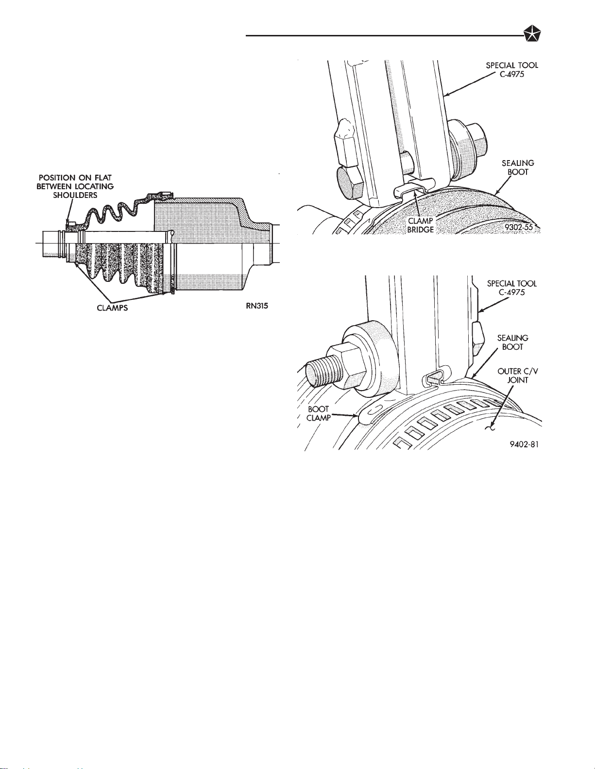
2 - 52 SUSPENSION AND DRIVESHAFTS
CAUTION: Seal must not be dimpled, stretched or
out of shape in any way. If seal is NOT shaped
correctly, equalize pressure in seal and shape it by
hand.
(6) Position outer C/V joint seal boot, into boot retaining groove on outer C/V joint housing (Fig. 7).
Then install seal boot to outer C/V joint retaining
clamp evenly on sealing boot.
Fig. 8 Crimping Tool Installed On Sealing Boot
Clamp
Fig. 7 Boot and Clamp Positioning
(7) Clamp sealing boot onto outer C/V joint housing
using Crimper, Special Tool C-4975 and the following
procedure. Place crimping tool C-4975 over bridge of
clamp (Fig. 8). Tighten nut on crimping tool C-4975
until jaws on tool are closed completely together, face
to face (Fig. 9).
(8) Install the driveshaft requiring boot replacement back on the vehicle. See Servicing Driveshaft in
this section of the service manual for the required
drive shaft installation procedure.
Fig. 9 Sealing Boot Retaining Clamp Installed
Page 72

SUSPENSION AND DRIVESHAFTS 2 - 53
REAR SUSPENSION
INDEX
page page
General Information ....................... 53
Rear Crossmember ....................... 66
Rear Spindle ............................ 61
Rear Stabilizer Bar ........................ 68
GENERAL INFORMATION
The rear suspension used on the L.H. platform is a
fully independent rear suspension. The suspension
utilizes a MacPherson strut assembly at each rear
wheel of the vehicle.
CAUTION: Only frame contact hoisting equipment
can be used on L.H. platform vehicles. The L.H.
platform vehicles have a fully independent rear suspension. The L.H. platform vehicles can not be
hoisted using equipment designed to lift a vehicle
by the rear axle. If this type of hoisting equipment is
used damage to rear suspension components will
occur.
A forged rear spindle bolts to each rear strut assembly. The movement of the rear spindle is controlled laterally using lateral links going from the
front and rear of the spindle to the rear cross member. Fore and aft movement of the spindle is controlled by a trailing arm.
Rear Wheel Toe Setting Procedure ............ 55
Servicing Lateral Links ..................... 69
Servicing Rear Struts ...................... 55
Suspension Coil Springs ................... 61
The lateral links and trailing arm have rubber isolator bushings at each end. The lateral links are
attached to the rear crossmember and spindle, using
a common bolt and nut assembly at each end. The
trailing arm bolts to the bottom of the spindle and to
a bracket attached to the floor pan of the vehicle.
Lateral links, trailing arms and spindles are normally replaced only when the part has been damaged
or when the vehicle has been involved in an accident.
If a suspension part has been damaged, be sure to
check the underbody dimensions of the car. If the
underbody dimensions are not correct, the frame of
the vehicle must be straightened, before replacement
suspension components are installed.
Note: If a rear suspension component becomes
bent, damaged or fails, no attempt should be
made to straighten or repair it. Always replace
with a new component.
Page 73

2 - 54 SUSPENSION AND DRIVESHAFTS
Fig. 1 L.H. Platform Fully Independent Rear Suspension
Page 74

REAR WHEEL TOE SETTING PROCEDURE
Rear Wheel alignment adjustments can only
be made for the Toe In setting on the L.H. platform vehicles.
Toe is measured in degrees or inches and is the
distance the front edges of the tires are closer (or
farther apart) than the rear edges. See Front Wheel
Drive Specifications for Toe settings.
REAR WHEEL TOE ADJUSTMENT
(1) Prepare vehicle as described in the PreAlignment procedure.
(2) Loosen lateral link, adjustment link jamnuts
(Fig. 1). Rotate adjustment links as required to set
rear wheel Toe to specifications. Do not exceed the
maximum length dimensions of the lateral links
shown in (Fig. 2). Both dimensions must be
checked to ensure they do not exceed maximums allowed.
SUSPENSION AND DRIVESHAFTS 2 - 55
Fig. 2 Lateral Link Maximum Length Dimensions
(2) Remove the rear wheel and tire assembly from
the vehicle.
(3) If vehicle is equipped with rear disc brakes,
remove the rear caliper assembly from the adapter.
Refer to Rear Disk Brakes in Group 5 Brakes of this
Service manual for required caliper removal procedure. After removing caliper assembly store caliper by
hanging it from vehicle (Fig. 1). Do not let rear caliper assembly hang from flexible brake hose. If vehicle
is equipped with rear drum brakes, remove the brake
flex hose bracket from the support plate and wheel
cylinder (Fig. 2).
Fig. 1 Rear Wheel Toe Adjustment At Lateral Links
CAUTION:
The maximum lengths of the adjustable lateral link
at the locations shown in (Fig. 2) must not be
exceeded. If these maximum lengths are exceeded,
inadequate retention of adjustment link to the inner
and outer link may result. Ensure that the adjustment sleeve jam nuts are torqued to the required
specifications when the Toe setting procedure is
completed.
(3) Tighten lateral link, adjustment link locknuts to
65 Nzm (48 ft.lbs.) torque.
When setting rear (Toe In( on vehicle.
SERVICING REAR STRUTS
REMOVAL
(1) Raise vehicle on jackstands or centered on a
frame contact type hoist. See Hoisting in the Lubrication and Maintenance section of this manual, for the
required lifting procedure to be used for this vehicle.
Fig. 1 Storing Rear Caliper Assembly
(4) If vehicle is equipped with rear disc brakes,
remove rear braking disc from hub.
(5) If vehicle is equipped with rear disc brakes.
Remove the speed sensor cable routing tube on trailing arm and the routing bracket on the trailing arm
bracket to spindle (Fig. 3). If spindle and trailing
arm assembly is lowered from strut with the
Page 75

2 - 56 SUSPENSION AND DRIVESHAFTS
Fig. 2 Brake Hose Bracket And Tube
speed sensor cable attached damage to speed
sensor cable may occur.
taching link stud nut, at the stabilizer bar (Fig. 5).
The attaching link does not have to be removed from
strut assembly.
Fig. 5 Attachment Link To Stabilizer Bar Attaching
(8) Loosen and fully remove, the rear spindle to
strut assembly pinch bolt (Fig. 6).
Fig. 3 Speed Sensor Routing Tube And Bracket
(6) Remove the bolt (Fig. 4) attaching the lateral
links to the rear spindle assembly.
Fig. 4 Lateral Links To Spindle Attaching Bolt
(7) Install a thin open end wrench, on hex of attaching link stud to keep stud from spinning in link.
Remove the rear strut assembly to stabilizer bar at-
Fig. 6 Spindle To Strut Assembly Pinch Bolt
CAUTION: When inserting center punch into rear
spindle, use care so point of center punch does not
puncture strut assembly.
(9) Insert a center punch into the hole on the
spindle (Fig. 7). Center punch must be tapped into
spindle until jammed into hole. This will spread
spindle casting allowing it to be removed from strut
assembly.
(10) Using a hammer, tap on top surface of spindle
driving it down and off the end of the strut assembly
(Fig. 8).
(11) Let the rear spindle and assembled components hang from trailing arm (Fig. 9) while strut
assembly is out of the vehicle.
(12) Lower vehicle.
Page 76

Fig. 7 Center Punch Installed In Spindle
SUSPENSION AND DRIVESHAFTS 2 - 57
Fig. 8 Removing Spindle From Strut Assembly
NOTE: When removing rear strut assembly
from vehicle, access for the 3 rear strut assembly to strut tower attaching nuts is through the
trunk of the vehicle. See (Fig. 10) for access
location of the strut assembly attaching nuts in
trunk of vehicle.
(13) Remove the 3 rear strut assembly to rear strut
tower mounting nuts (Fig. 10) and then remove strut
assembly from vehicle.
INSPECTION
Inspect for evidence of fluid leakage from upper end
of reservoir. (Actual leakage will be a stream of fluid
running down and leaking off lower end). Slight seepage is not unusual and will not effect performance.
INSTALLATION
(1) Position strut assembly back in vehicle with the
3 studs on strut mount assembly through holes in
rear strut tower of vehicle. Install the 3 strut mount
to body attaching nuts onto mount studs (Fig. 10).
Fig. 9 Spindle Assembly Removed From Strut
Fig. 10 Rear Strut Assembly To Strut Tower
Mounting Nuts
Using a crow foot and 3/8 in. torque wrench, torque
the 3 strut mount to strut tower attaching nuts to 28
Nzm (20 ft. lbs).
(2) Install spindle onto bottom of the strut assembly. Push and or tap spindle assembly onto strut,
until notch in spindle is tightly seated against locating tap on strut assembly (Fig. 11). Then remove
center punch from hole in spindle. Install spindle to
strut assembly pinch bolt into spindle (Fig. 11).
Torque spindle to strut assembly pinch bolt to 55 Nzm
(40 ft. lbs.).
(3) Install the lateral links to spindle attaching bolt
(Fig. 12). Torque the lateral links to spindle attaching
bolt to 140 Nzm (105 ft. lbs.).
(4) Install stabilizer bar attaching link onto stabilizer bar (Fig. 13). Install stabilizer link to stabilizer
Page 77

2 - 58 SUSPENSION AND DRIVESHAFTS
(5) Mount rear speed sensor cable routing tube to
rear trailing arm (Fig. 14). Then mount speed sensor
cable routing clip (Fig. 14) to the trailing arm to rear
spindle bracket.
Fig. 11 Spindle Mounted To Strut Assembly
Fig. 12 Lateral Links To Spindle Attaching Bolt
bar attaching nut (Fig. 13). Torque the stabilizer link
to stabilizer bar attaching nut to 95 Nzm (70 ft. lbs.).
Fig. 14 Speed Sensor Routing Tube And Bracket
(6) If vehicle is equipped with rear disc brakes,
install rear braking disc on hub. Carefully install rear
brake caliper over braking disc and install on adapter.
Tighten rear caliper assembly to adapter mounting
bolts to 22 Nzm (192 in. lbs.). If required, refer to Rear
Disc Brakes in Group 5 Brakes of this service manual
for required rear brake caliper installation procedure.
(7) If vehicle is equipped with rear drum brakes
install rear brake flex hose onto wheel cylinder and
support plate (Fig. 15). First torque brake hose to
wheel cylinder tube nut to 17 Nzm (145 in. lbs.). Then
torque brake hose bracket to brake support plate bolt
to8Nzm (75 in. lbs).
Fig. 13 Attachment Link To Stabilizer Bar Attaching
Fig. 15 Brake Hose Bracket And Tube Nut
(8) If vehicle has rear drum brakes, brake system
will require bleeding. Refer to Bleeding Brake System
in the Service Adjustments Section of Group 5 Brakes
in this service manual.
(9) Install wheel and tire assembly on vehicle. Then
torque all wheel mounting stud nuts in proper sequence (Fig. 16) until all nuts are torqued to half
Page 78

specification. Then repeat tightening sequence to full
specified torque of 129 Nzm (95 ft. lbs.).
Fig. 16 Tightening Wheel Nuts
(10) Lower vehicle to the ground.
(11) Check and reset rear wheel TOE to specifica-
tions if required.
SUSPENSION AND DRIVESHAFTS 2 - 59
STRUT DISASSEMBLY
The rear strut is not serviced and must be replaced
as an assembly if found to be defective. The strut is
available with 2 calibrations, be sure strut is replaced
with an assembly of the same calibration.
The components of the strut assembly listed below
are replaceable if found to be defective.
• Coil spring (Coil springs come in a standard and
high rate be sure spring is replaced with a spring of
the correct rate.)
• Dust shield
• Mount assembly
• Jounce Bumper
• Lower Spring Isolator
• Shaft Nut
(1) Remove strut assembly requiring service from
the vehicle. Refer to Strut Assembly Removal in Servicing Rear Struts, in this section of the service
manual.
(2) Position strut assembly in a vise (Fig. 1). Using
paint or equivalent, mark the strut unit, lower spring
isolator, spring and upper strut mount for indexing of
the parts at assembly.
(3) Position Spring Compressors, Special Tool
C-4838 on the strut assembly spring (Fig. 1). Compress coil spring until all load is removed from upper
strut mount assembly.
(4) Install Strut Rod Socket, Special Tool, L-4558
on strut shaft nut (Fig. 2). Usea8mmallen wrench
inserted into end of strut shaft to keep strut shaft
from turning (Fig. 2). Remove strut shaft nut from
shaft.
(5) Remove upper strut mount assembly from strut
shaft (Fig. 3).
Fig. 1 Compressing Strut Assembly Coil Spring
Fig. 2 Removing Strut Shaft Nut
(6) Remove the coil spring and spring compressor
as an assembly from the strut (Fig. 4).
(7) Remove the plate, dust shield and jounce
bumper as an assembly from the strut unit (Fig. 5).
(8) Remove lower spring isolator from strut assem-
bly (Fig. 6).
Inspect all disassembled components for signs of
abnormal wear or failure replacing any components
as required. Inspect strut unit for signs of abnormal
oil leakage and for loss of gas charge. To check for
loss of gas charge in strut unit. Push strut shaft into
Page 79

2 - 60 SUSPENSION AND DRIVESHAFTS
Fig. 3 Upper Strut Mount Removal
Fig. 4 Coil Spring Remove And Replace
body of strut and release, strut shaft should return to
its fully extended position. If strut shaft does not
return to its fully extended position replace strut
unit.
STRUT REASSEMBLY
(1) Install original or new, lower spring isolator on
strut unit (Fig. 6). If installing original isolator align
paint marks on isolator and strut unit.
(2) Install jounce bumper into dust shield (Fig. 7).
Install plate on top of dust shield and into jounce
bumper (Fig. 8).
(3) Install the dust shield, jounce bumper and top
plate as an assembly onto the strut unit (Fig. 5).
(4) Lower the coil spring and compressor onto the
strut unit (Fig. 4) Align the paint mark on the spring
with the paint mark on the strut unit (Fig. 1).
Fig. 5 Plate, Dust Shield And Jounce Bumper
Remove And Replace
Fig. 6 Lower Spring Isolator
(5) Install the upper strut mount assembly onto the
strut shaft, aligning paint marks (Fig. 3). Install the
upper strut mount to strut shaft retaining nut on
strut shaft.
(6) Using Strut Rod Socket, Special Tool, L-4558 and a
8 mm allen wrench to keep strut shaft from turning.
Torque the strut shaft nut to 95 Nzm (70 ft. lbs.).
(7) Equally loosen the Spring Compressors, Special
Tool C-4838 until spring is seated on upper strut
mount and all tension is relieved from the spring
compressors.
(8) Install the strut assembly back into the vehicle.
Refer to Strut Assembly Removal in Servicing Rear
Struts in this section of the service manual.
(9) Check and reset rear wheel TOE to specifications if required.
Page 80

SUSPENSION AND DRIVESHAFTS 2 - 61
Fig. 7 Jounce Bumper Installed Into Dust Shield
Fig. 8 Plate Installation Into Jounce Bumper And
Dust Shield
SUSPENSION COIL SPRINGS
Springs are rated separately for each side of vehicle
depending on optional equipment and type of service.
During service procedures where both springs are
removed, mark springs (Chalk, Tape, etc.) (Fig. 9) to
ensure installation in original position. If the coils
springs require replacement. Be sure that the
springs needing replacement, are replaced with
springs meeting the correct load and spring
rate for the vehicle.
During service procedures requiring the removal or installation of a coil spring with
Spring Compressor, Special Tool C-4838. It is
required that five coils be captured within the
jaws of the tool (Fig. 9).
Fig. 9 Identifying Coil Springs
tion and Maintenance section of this manual, for the
required lifting procedure to be used for this vehicle.
(2) Remove the rear wheel and tire assembly from
the vehicle.
(3) If vehicle is equipped with rear disc brakes,
remove the rear caliper assembly from the adapter.
Refer to Rear Disk Brakes in Group 5 Brakes of this
Service manual for required caliper removal procedure. After removing caliper assembly store caliper by
hanging it from frame of vehicle (Fig. 1). Do not let
weight of rear caliper assembly hang from flexible
brake hose. If vehicle is equipped with rear drum
brakes, remove the brake flex hose bracket from the
support plate and wheel cylinder (Fig. 2).
REAR SPINDLE
REMOVE
(1) Raise vehicle on jackstands or centered on a
frame contact type hoist. See Hoisting in the Lubrica-
Fig. 1 Storing Rear Caliper Assembly
Page 81

2 - 62 SUSPENSION AND DRIVESHAFTS
Fig. 2 Brake Hose Bracket And Tube
(4) If vehicle is equipped with rear disc brakes,
remove rear braking disc from hub. If vehicle is
equipped with rear drum brakes, remove the brake
drum from the hub.
(5) On all rear brake applications, remove rear hub
and bearing assembly cotter pin and nut retainer.
Then remove hub retaining nut and washer from
spindle (Fig. 3). Then remove hub and bearing assembly from spindle.
Fig. 4 Brake Support Plate Mounting Bolts
Fig. 3 Rear Hub And Bearing Retaining Nut and
Washer Removal
(6) On vehicles equipped with rear drum brakes.
Remove the 4 bolts attaching the rear brake support
plate to the rear spindle (Fig. 4). Then remove rear
brake support plate with parking brake cable attached, from rear spindle.
(7) If vehicle is equipped with Anti-Lock brakes.
Remove speed sensor head from the rear disc brake
adapter (Fig. 5).
(8) On vehicles equipped with rear disc brakes. Remove the 4 bolts attaching the disc brake adapter to
Fig. 5 Speed Sensor Head Removal From Adapter
the rear spindle (Fig. 6). Then remove the adapter,
disc shield, park brake shoes and park brake cable as
an assembly from spindle.
Fig. 6 Disc Brake Adapter Mounting
Page 82

(9) If vehicle is equipped with Anti-Lock brakes.
Remove the speed sensor cable routing tube on trailing arm and the routing bracket on the trailing arm
bracket to spindle (Fig. 7). If trailing arm is low-
ered from strut with the speed sensor cable attached damage to speed sensor cable may occur.
Fig. 7 Speed Sensor Routing Tube And Bracket
(10) Remove bolt attaching trailing arm to trailing
arm bracket on bottom of spindle (Fig. 8).
SUSPENSION AND DRIVESHAFTS 2 - 63
Fig. 9 Lateral Links To Spindle Attaching Bolt
Fig. 8 Trailing Arm To Spindle Bracket Bolt
(11) Remove the bolt (Fig. 9) attaching the lateral
links to the rear spindle assembly.
(12) Loosen and fully remove, the rear spindle to
strut assembly pinch bolt (Fig. 10).
CAUTION: When inserting center punch into rear
spindle, use care so point of center punch does not
puncture strut assembly.
(13) Insert a center punch into the hole on the
spindle (Fig. 11). Center punch must be tapped into
spindle until jammed into hole. This will spread
spindle casting allowing it to be removed from strut
assembly.
(14) Using a hammer, tap on top surface of spindle
driving it down and off the end of the strut assembly
(Fig. 12).
Fig. 10 Spindle To Strut Assembly Pinch Bolt
Fig. 11 Center Punch Installed In Spindle
INSTALLATION
(1) Install spindle onto the bottom of the strut assembly (Fig 13). Push and or tap spindle assembly
onto strut, until notch in spindle is tightly seated
against locating tap on strut assembly (Fig. 13). Then
Page 83

2 - 64 SUSPENSION AND DRIVESHAFTS
Fig. 12 Removing Spindle From Strut Assembly
remove center punch from hole in spindle. Install
spindle to strut assembly pinch bolt into spindle (Fig.
13). Torque spindle to strut assembly pinch bolt to 55
Nzm (40 ft. lbs.).
Fig. 13 Spindle Mounted To Strut Assembly
(2) Install the lateral links to spindle attaching bolt
(Fig. 14) Torque the lateral links to spindle attaching
bolt to 140 Nzm (105 ft. lbs.).
(3) Install bolt attaching trailing arm to trailing
arm bracket on bottom of spindle (Fig. 15). Torque
trailing arm to trailing arm bracket attaching bolt to
100 Nzm (74 ft. lbs.).
(4) If vehicle is equipped with Anti-Lock Brakes.
Mount rear speed sensor cable routing tube to the
rear trailing arm and speed sensor cable routing
bracket to trailing arm bracket at rear spindle (Fig.
16).
(5) On vehicles equipped with rear drum brakes.
Install the rear brake support plate onto the spindle
(Fig. 17). Install the 4 bolts attaching the rear brake
support plate to the rear spindle (Fig. 17). Torque the
brake support plate to spindle mounting bolts to 115
Nzm (85 ft. lbs.).
Fig. 14 Lateral Links To Spindle Attaching Bolt
Fig. 15 Trailing Arm To Spindle Bracket Bolt
Fig. 16 Speed Sensor Routing Tube And Bracket
(6) On vehicles equipped with rear disc brakes. In-
stall the disc brake adapter back on the spindle (Fig.
18) Install the 4 bolts attaching the disc brake
adapter to the rear spindle (Fig. 18). Torque the disc
brake adapter to spindle mounting bolts to 115 Nzm
(85 ft. lbs.).
(7) If vehicle is equipped with Anti-Lock brakes.
Install the speed sensor head into the rear disc brake
Page 84

SUSPENSION AND DRIVESHAFTS 2 - 65
(8) Install the rear hub and bearing assembly on
the rear spindle. Install hub and bearing assembly
retaining washer and nut on spindle (Fig. 20). Torque
hub and bearing retaining nut to 168 Nzm (124 ft.
lbs).
Fig. 17 Brake Support Plate Mounting Bolts
Fig. 18 Disc Brake Adapter Mounting
adapter (Fig. 19). Torque speed sensor head to
adapter attaching bolt to 7 Nzm (60 in. lbs.).
Fig. 20 Rear Hub And Bearing Retaining Nut and
Washer Removal
(9) If vehicle is equipped with rear disc brakes,
install rear braking disc on hub. If vehicle is equipped
with rear drum brakes, install the brake drum on
hub.
(10) If vehicle is equipped with rear disc brakes,
install rear braking disc on hub. Carefully install rear
brake caliper over braking disc and install on adapter.
Tighten the caliper assembly to adapter mounting
bolts to 22 Nzm (192 in. lbs.). Refer to Rear Disc
Brakes in Group 5 Brakes in this service manual for
required caliper installation procedure.
(11) If vehicle is equipped with rear drum brakes
install rear brake flex hose onto wheel cylinder and
support plate (Fig. 21). Torque the brake hose to
wheel cylinder tube nut to 17 Nzm (145 in. lbs.).
Torque the brake hose bracket to support plate bolt to
8Nzm (75 in. lbs).
(12) If vehicle has rear drum brakes, brake system
will require bleeding. Refer to Bleeding Brake System
in the Service Adjustments Section of Group 5 Brakes
in this service manual.
(13) Install wheel and tire assembly on vehicle.
Tighten the wheel mounting stud nuts in proper sequence (Fig. 22) until all nuts are torqued to half
specification. Then repeat the tightening sequence to
the full specified torque of 129 Nzm (95 ft. lbs.).
(14) Lower vehicle to the ground.
(15) Check and reset rear wheel TOE to specifications if required.
Fig. 19 Speed Sensor Head Installed In Adapter
Page 85

2 - 66 SUSPENSION AND DRIVESHAFTS
REAR CROSSMEMBER
The L.H. platform vehicles are available with two
different rear crossmembers depending on the suspension package the vehicle was built with. The
crossmembers visually look the same between the
standard and performance suspension packages, but
the mounting location for the lateral links is different. The performance suspension crossmember is
identified by a identification hole in the crossmember (Fig. 1). The performance crossmember identification hole is located on left side of crossmember on
the rear vertical wall. If crossmember is replaced
be sure the correct crossmember is installed or
handling of the vehicle will be adversely affected.
Fig. 21 Brake Hose Bracket And Tube Nut
Fig. 22 Tightening Wheel Nuts
REMOVE
(1) Raise vehicle on jackstands or centered on a
frame contact type hoist. See Hoisting in the Lubrication and Maintenance section of this manual, for the
required lifting procedure to be used for this vehicle.
(2) Remove both rear wheel and tire assemblies
from the vehicle.
(3) Position a transmission jack under the fuel tank
just forward of the crossmember to help support fuel
tank when crossmember is removed.
(4) Remove the nut and bolt on each side of vehicle
attaching the lateral links to the spindle (Fig. 2).
(5) Remove the 4 bolts attaching rear crossmember
to frame rails (Fig. 3)
(6) Lower the crossmember and lateral links as an
assembly out of the vehicle.
Fig. 1 Rear Suspension Crossmember
Page 86

Fig. 2 Lateral Link Attachment To Spindle
SUSPENSION AND DRIVESHAFTS 2 - 67
(3) Align lateral links with spindles and install the
lateral link to spindle attaching bolts (Fig. 2). Torque
the lateral link to spindle attaching bolts to 140 Nzm
(105 ft. lbs.).
(4) Remove transmission jack supporting fuel tank.
(5) Install wheel and tire assembly on vehicle.
Tighten the wheel mounting stud nuts in proper sequence (Fig. 4) until all nuts are torqued to half
specification. Then repeat the tightening sequence to
the full specified torque of 129 Nzm (95 ft. lbs.).
Fig. 3 Crossmember To Frame Rail Attaching Bolts
(7) Transfer lateral links to the replacement crossmember before installing crossmember back in vehicle. Adjustable lateral link to be positioned to
the rear of vehicle on crossmember. Torque the
lateral links to crossmember attaching bolts to 140
Nzm (105 ft. lbs.). Install lateral link to crossmem-
ber bolts so head of bolt will be to front of
vehicle when crossmember is installed.
INSTALL
(1) Install the crossmember and lateral links back
into vehicle as an assembly.
(2) Position crossmember on frame rails and install
the 4 crossmember to frame rail attaching bolts (Fig.
3). Torque the crossmember to frame rail attaching
bolts to 95 Nzm (70 ft. lbs.).
Fig. 4 Tightening Wheel Nuts
(6) Lower vehicle to the ground.
(7) Check and reset rear wheel TOE to specifica-
tions if required.
Page 87

2 - 68 SUSPENSION AND DRIVESHAFTS
REAR STABILIZER BAR SERVICE
REMOVE
(1) Raise vehicle on jackstands or centered on a
frame contact type hoist. See Hoisting in the Lubrication and Maintenance section of this manual, for the
required lifting procedure to be used for this vehicle.
(2) Remove both rear wheel and tire assemblies
from the vehicle.
(3) Position a transmission jack under the fuel tank
just forward of the crossmember to help support fuel
tank when crossmember is removed.
(4) Remove the 4 crossmember to frame rail attaching bolts (Fig. 1).
Fig. 2 Stabilizer Bar To Link Attaching
bar attaching nut (Fig. 2). Torque the stabilizer link
to stabilizer bar attaching nut to 95 Nzm (70 ft. lbs.).
(3) Install fuel tank back in vehicle. Refer to Group
14 Fuel, in this service manual for the required fuel
tank installation procedure.
Fig. 1 Crossmember To Frame Rail Attaching Bolts
(5) Remove fuel tank. Refer to Group 14 Fuel, in
this service manual for the required fuel tank removal procedure.
(6) Remove the stabilizer bar to link assembly attaching nuts (Fig. 2)
(7) Remove stabilizer bar and isolator bushings as
an assembly from the vehicle.
STABILIZER BAR AND BUSHING INSPECTION
Inspect for broken or distorted retainers and bushings. If bushing replacement is required, bushing can
be removed by opening slit in bushing and removing
bushing from around stabilizer bar.
CAUTION: The sway bar bracket bolts must be replaced after loosening or removing them. Only use
original equipment bolts as replacements.
(4) Position crossmember on frame rails and install
the 4 crossmember to frame rail attaching bolts (Fig.
1). Torque the crossmember to frame rail attaching
bolts to 95 Nzm (70 ft. lbs.).
(5) Remove transmission jack supporting fuel tank.
(6) Install wheel and tire assembly on vehicle.
Tighten the wheel mounting stud nuts in proper sequence (Fig. 3) until all nuts are torqued to half
specification. Then repeat the tightening sequence to
the full specified torque of 129 Nzm (95 ft. lbs.).
INSTALL
(1) Install the stabilizer bar and isolator bushings
back into the vehicle as an assembly. Position stabilizer bar so it is centered in the vehicle so it does not
contact other suspension components or vehicle body.
(2) Install the stabilizer bar attaching link onto
stabilizer bar. Install the stabilizer link to stabilizer
Fig. 3 Tightening Wheel Nuts
(7) Lower vehicle to the ground.
(8) Check and reset rear wheel TOE to specifica-
tions if required.
Page 88

SUSPENSION AND DRIVESHAFTS 2 - 69
Fig. 1 Rear Suspension Lateral Links
SERVICING LATERAL LINKS
The lateral links are only serviced as complete assemblies. The isolator bushings used in the lateral
links are not serviced as separate components. The
left and right lateral links are serviced using different
procedures. See procedures below for the side of the
vehicle requiring service to the lateral links.
LEFT LATERAL LINKS
REMOVE
Raise vehicle on jackstands or centered on a
(1)
frame contact type hoist. See Hoisting in the Lubrication and Maintenance section of this manual, for
the required lifting procedure to be used for this
vehicle.
(2) Remove left rear wheel and tire assembly from
the vehicle.
(3) Remove the nut and bolt attaching left lateral
links to the spindle (Fig. 2).
(4) Remove the nut and bolt attaching the left lateral links to the rear crossmember (Fig. 3) Remove
lateral links from vehicle.
Fig. 2 Lateral Link Attachment To Spindle
Fig. 3 Left Lateral Links To Crossmember Bolt
INSTALL
(1) Replacement lateral links are installed on the
crossmember in the following order.
• Solid lateral link is installed on crossmember toward the front of the vehicle.
• The adjustable lateral link is installed on crossmember toward rear of vehicle, with the adjustable
link positioned toward the spindle (Fig. 1).
Page 89

2 - 70 SUSPENSION AND DRIVESHAFTS
(2) Install the lateral link attaching bolt at the
spindle and crossmember. Note: Both lateral link
attaching bolts must be install, so head of bolt is
facing front of vehicle (Fig. 2 and 3).
(3) Torque both lateral link attaching bolts to 140
Nzm (105 ft. lbs.).
(4) Install wheel and tire assembly on vehicle.
Tighten the wheel mounting stud nuts in proper sequence (Fig. 4) until all nuts are torqued to half
specification. Then repeat the tightening sequence to
the full specified torque of 129 Nzm (95 ft. lbs.).
Fig. 5 Lateral Link Attachment To Spindle
Fig. 4 Tightening Wheel Nuts
(5) Lower vehicle to the ground.
(6) Check and reset rear wheel TOE to specifications if required.
RIGHT LATERAL LINKS
To allow for removal of right rear lateral links to
rear crossmember attaching bolt. The rear crossmember will have to be lowered so attaching bolt will clear
fuel tank for removal and installation.
REMOVE
(1) Raise vehicle on jackstands or centered on a
frame contact type hoist. See Hoisting in the Lubrication and Maintenance section of this manual, for the
required lifting procedure to be used for this vehicle.
(2) Remove right rear wheel and tire assembly from
the vehicle.
(3) Remove the nut and bolt attaching right lateral
links to the spindle (Fig. 5).
(4) Position a transmission jack under the fuel tank
just forward of the crossmember to help support fuel
tank when crossmember is lowered.
(5) Remove the 4 crossmember to frame rail attaching bolts (Fig. 6).
(6) Lower rear crossmember far enough so right
lateral links to crossmember attaching bolt will clear
fuel tank.
Fig. 6 Crossmember To Frame Rail Attaching Bolts
(7) Remove the nut and bolt attaching the right
lateral links to the rear crossmember (Fig. 7) Remove
lateral links from vehicle.
INSTALL
(1) Replacement lateral links are installed on the
crossmember in the following order.
• Solid lateral link is installed on crossmember toward the front of the vehicle.
• The adjustable lateral link is installed on crossmember toward rear of vehicle, with the adjustable
link positioned toward the spindle (Fig. 1).
(2) Install the right lateral links attaching bolt at
the crossmember. Note: Right lateral link attach-
ing bolts MUST be install, so head of bolt is
facing front of vehicle (Fig. 5 and 7).
Page 90

Fig. 7 Right Lateral Links To Crossmember Bolt
(3) Position crossmember on frame rails and install
the 4 crossmember to frame rail attaching bolts (Fig.
6). Torque the crossmember to frame rail attaching
bolts to 95 Nzm (70 ft. lbs.).
(4) Torque the lateral links to crossmember attach-
ing bolt to 140 Nzm (105 ft. lbs.).
(5) Align right lateral links with spindle and install
the lateral link to spindle attaching bolt (Fig. 5).
Torque the lateral link to spindle attaching bolt to
140 Nzm (105 ft. lbs.).
SUSPENSION AND DRIVESHAFTS 2 - 71
(6) Install wheel and tire assembly on vehicle.
Tighten the wheel mounting stud nuts in proper sequence (Fig. 8) until all nuts are torqued to half
specification. Then repeat the tightening sequence to
the full specified torque of 129 Nzm (95 ft. lbs.).
Fig. 8 Tightening Wheel Nuts
(7) Lower vehicle to the ground.
(8) Check and reset rear wheel TOE to specifications if required.
Page 91

2 - 72 SUSPENSION AND DRIVESHAFTS
ALIGNMENT SPECIFICATIONS AT CURB HEIGHT
1994 New Yorker, LHS, Concorde, Intrepid and Vision
Publication No. 81-270-4140
TSB 02-13-94 September 23, 1994
SPECIFICATIONS
FRONT SUSPENSION TORQUE SPECIFICATIONS
REAR SUSPENSION TORQUE SPECIFICATIONS
Page 92

BRAKES 5 - 1
BRAKES
CONTENTS
page page
ANTI-LOCK BRAKE SYSTEM—TEVES MARK IV
SYSTEM ............................. 75
BRAKE DISC (ROTOR) ................... 47
BRAKE SUPPORT ASSEMBLY ............. 22
FRONT DISC BRAKES .................... 28
GENERAL INFORMATION .................. 1
HYDRAULIC SYSTEM CONTROL VALVES .... 24
KELSEY HAYES DOUBLE PIN CALIPER
ASSEMBLY ........................... 31
GENERAL INFORMATION
Throughout this group, references may be made to
a particular L.H. platform vehicle by letter or number
designation. A chart showing the break down of these
designations is included in the Introduction Section
at the front of this service manual.
The L.H. platform vehicles are available with 4
different types of brake systems. The standard brake
system consists of front disc brakes and rear drum
brakes which are not available with Anti-Lock. The
second optional brake system is 4 wheel disc brakes
without Anti-Lock. The third optional brake system is
Anti-Lock brakes, which is only available with front
and rear disc brakes. The fourth optional brake system is 4 wheel disc brakes with traction control. The
traction control system is dependent on the Anti-Lock
system and is not available without Anti-Lock.
Standard brake equipment consists of:
• Double pin floating caliper front disc brakes.
• Rear automatic adjusting drum brakes.
• Proportioning valve on non Anti-Lock brakes.
• Master cylinder.
• Vacuum power booster.
• Double pin floating caliper rear disc brakes are
available on some models and standard with AntiLock.
The Anti-Lock braking system, uses the standard
power brake system caliper assemblies, braking
discs, pedal assembly, brake lines and hoses. The
unique parts of the Anti-Lock braking system consists of the following components. Unique proportioning valves, wheel speed sensors, tone wheels,
electronic control unit, hydraulic control unit and
the conventional master cylinder and power booster.
MASTER CYLINDER ..................... 69
PARKING BRAKES ...................... 51
POWER BRAKES ........................ 72
REAR DISC BRAKES ..................... 38
REAR WHEEL DRUM BRAKES ............. 15
SERVICE ADJUSTMENTS .................. 4
WHEEL BEARINGS ...................... 74
WHEEL CYLINDERS ..................... 20
These components will be described in detail in the
Anti-Lock brake section in this group of the service
manual.
The front disc brake shoes have non-asbestos semi-
metallic linings.
The hydraulic brake system (Fig. 1 2 and 3) is
diagonally split on both the Non-ABS and ABS braking system. With the left front and right rear brakes
on one hydraulic system and the right front and left
rear on the other.
Fig. 1 Diagonally Split Braking System
(Typical Non-ABS System)
All available brake systems on the L.H. platform
vehicles, except rear drum brakes use the same type
of brake line fittings and tubing flares. The brake line
and fittings used is double wall tubing with ISO
Page 93

5 - 2 BRAKES
Fig. 2 Proper Tube Nut Thread Size And Tube Routing (Non-ABS Equipped)
style tubing flares and fittings at all tubing joint
locations. See (Figs. 2 and 3) for specific joint locations and tube fitting size.
Vehicles equipped with rear drum brakes. Use conventional double inverted style flares at the brake
flex hose to wheel cylinder connections.
Avoid scuffing the brake tubes when servicing.
Scuffing the brake tubes will scrape off the anticorrosion coating on the brake tubes.
CAUTION: At no time when servicing a vehicle, can
a sheet metal screw, bolt or other metal fastener be
installed in the shock tower to take the place of an
original plastic clip. Also, NO holes can be drilled
into the front shock tower in the area shown in (Fig.
4), for the installation of any metal fasteners into the
shock tower.
Because of the minimum clearance in this area
(Fig.4) installation of metal fasteners could damage
the coil spring coating and lead to a corrosion failure of the spring. If a plastic clip is missing, or is
lost or broken during servicing a vehicle, replace
only with the equivalent part listed in the Mopar
parts catalog.
The L.H. platform front disc brakes, use a double
pin, single piston floating caliper design supplied by
Kelsey-Hayes. The front disc brake caliper assembly
mounts directly to rails on the steering knuckle and
is secured to the steering knuckle using 2 bolts.
CAUTION: Caliper pistons, boots and seals for the
different caliper assemblies used on the front and
rear disc brake assemblies are not interchangeable.
Misusage could result in a complete brake system
failure. Be sure that the parts are replaced with the
correct replacement parts, refer to the parts book
for the type and model year of the vehicle being
worked on.
The master cylinder is anodized, lightweight aluminum, with a bore size of 23.8mm (15/16 in.).
Page 94

BRAKES 5 - 3
Fig. 3 Proper Nut Thread Size And Tube Routing (ABS Equipped)
Fig. 4 Shock Tower To Spring Minimum Clearance
Area
Page 95

5 - 4 BRAKES
SERVICE ADJUSTMENTS
INDEX
page page
Adjusting Rear Service Brakes ................4
Bleeding Brake System ..................... 5
Brake Hose and Tubing ..................... 7
Master Cylinder Fluid Level ..................4
MASTER CYLINDER FLUID LEVEL
NON-ABS AND ABS BRAKES
Check master cylinder reservoir brake fluid level a
minimum of twice a year.
Master cylinder brake fluid reservoirs used on all
L.H. platform vehicles include a brake fluid level
sensor. The brake fluid level sensor location is in the
body of the brake fluid reservoir (Fig. 1). In the event
of low brake fluid level in the brake fluid reservoir,
the RED brake warning light in the instrument panel
will turn on.
Master cylinder assembly, brake fluid reservoirs on
both standard and Anti-Lock brake systems. Are
marked with a MAX fill line indicating the brake
fluid reservoirs proper fluid level (Fig. 1).
When filling brake fluid reservoir, use only
Mopart brake fluid or an equivalent stored in a
tightly sealed container. Brake fluid must conform to DOT 3, specifications.
If necessary, add brake fluid to brake fluid reservoir, bringing brake fluid level to the MAX fill line
shown on fluid reservoir (Fig. 1).
DO NOT use brake fluid with a lower boiling point
then DOT 3, as brake failure could result during
prolonged hard braking.
DO NOT use petroleum-based fluid because seal
damage in the brake system will result.
Road Wheel Stud Nut Tightening ..............6
Stop Lamp Switch Adjustment ................ 9
Testing Application Adjuster Operation .......... 5
Testing for Brake Fluid Contamination ........... 6
Fig. 1 Master Cylinder Fluid Level
(ABS And Non-ABS)
ADJUSTING REAR SERVICE BRAKES
Normally, self adjusting drum brakes will not
require manual brake shoe adjustment. Although in the event of a brake reline it is advisable to make the initial adjustment manually to
speed up the adjusting time.
(1) Raise the vehicle so all wheels are free to turn.
See Hoisting Recommendations in the Lubrication
And Maintenance Section, at the front of this service
manual.
(2) Remove rear brake adjusting hole rubber plug
(Fig. 1), from the rear brake shoe support plate.
(3) Be sure parking brake lever is fully re-
leased.
(4) Insert a medium blade screwdriver (Fig. 2) or
equivalent through the adjusting hole in support
plate and against star wheel of adjusting screw. Move
Fig. 1 Brake Adjusting Hole Plug
handle of tool downward until a slight drag is felt
when the road wheel is rotated.
(5) Insert a thin screwdriver or piece of welding rod
into brake adjusting hole (Fig. 2). Push adjusting
lever out of engagement with star wheel. Care
should be taken so as not to bend adjusting
lever or distort lever spring. While holding adjust-
ing lever out of engagement with star wheel, back off
star wheel to ensure a free wheel with no brake shoe
drag.
Page 96

Fig. 2 Rear Brake Shoe Adjustment
(6) Repeat above adjustment at the other rear
wheel. Install adjusting hole rubber plugs (Fig. 1) in
rear brake supports.
TESTING APPLICATION ADJUSTER OPERATION
Place the vehicle on a hoist with a helper in the
driver’s seat to apply the brakes. Remove the access
plug from the rear adjustment slot in each brake
support plate (Fig. 1) to provide visual access to brake
adjuster star wheel. Then, to eliminate the possibility
of maximum adjustment, where the adjuster does not
operate because the closest possible adjustment has
been reached. Back the star wheel off approximately
30 notches. It will be necessary to hold the adjuster
lever away from the star wheel to permit this adjustment.
Spin the wheel and brake drum in the forward
direction, and with a greater than normal force apply
the brakes suddenly. This sudden application of force
will cause the leading brake shoe to leave the anchor.
The wrap up effect will move the leading shoe, and
the spring will pull the adjuster lever down. Upon
application of the brake pedal, the lever should move
down, turning the star wheel. Thus, a definite rotation of the adjuster star wheel can be observed if the
automatic adjuster is working properly. If one or more
adjusters do not function properly, the respective
drum must be removed for adjuster servicing.
BRAKES 5 - 5
PRESSURE BLEEDING
Before removing the master cylinder cover, wipe it
clean to prevent dirt and other foreign matter from
dropping into the master cylinder.
CAUTION: Use bleeder tank Special Tool C-3496-B
or equivalent, with Snap-On adapter BB400-9A or
equivalent (Fig. 1 and 2), to pressurize the brake
hydraulic system for bleeding.
Fig. 1 Pressure Bleeding Adapter Mounted On Fluid
Reservoir
BLEEDING BRAKE SYSTEM
CAUTION: For bleeding the L.H. platform Anti-Lock
brakes hydraulic system, see the Anti-Lock Brake
system service procedures in this group of the service manual. It describes in detail the required procedure which needs to be followed when bleeding
the Anti-Lock brake system.
Fig. 2 Pressure Bleeding Vehicle Brake System
Follow pressure bleeder manufacturer’s instructions, for use of pressure bleeding equipment.
When bleeding the brake system. Some air may be
trapped in the brake lines or valves far upstream. As
much as ten feet from the bleeder screw (Fig. 3).
Therefore, it is essential to have a fast flow of a large
Page 97

5 - 6 BRAKES
volume of brake fluid when bleeding the brakes. This
will ensure all the air is bled from the brakes hydraulic system.
Fig. 3 Trapped Air in Brake Line
(1) Remove rubber dust caps from all 4 bleeder
screws.
(2) Attach a clear hose to the bleeder screw at one
wheel and feed the hose into a clear jar containing
fresh brake fluid (Fig. 4).
Enough fluid has not passed through the system to
expel all the trapped air. Be sure to monitor the fluid
level in the pressure bleeder. It must stay at the
proper level so air will not be allowed to re-enter the
brake system through the master cylinder.
(6) Replace all 4 bleeder screw rubber dust caps.
BLEEDING WITHOUT A PRESSURE BLEEDER
If a pressure bleeder is not available. A good brake
fluid flow can be obtained by manual bleeding of the
brake hydraulic system, following these steps.
(1) Remove rubber duct caps from all 4 bleeder
screws.
(2) Attach a clear hose to the bleeder screw at one
wheel and feed the hose into a clear jar containing
fresh brake fluid (Fig. 4).
(3) Pump the brake pedal three or four times and
hold it down before the bleeder screw is opened.
(4) Then open the bleeder screw at least 1 full turn.
When the bleeder screw opens the brake pedal will
drop all the way to the floor.
(5) Release the brake pedal only after the bleeder
screw is closed.
(6) Repeat steps 1 through 3, four or five times at
each bleeder screw. This should pass a sufficient
amount of fluid to expel all the trapped air from the
brakes hydraulic system. Be sure to monitor brake
fluid level in master cylinder fluid reservoir, to ensure
it stays at a proper level. This will ensure air does not
re-enter brake hydraulic system through master cylinder.
(7) Only after a short stroke and solid brake pedal
feel is obtained. Test drive vehicle to ensure brakes
are operating correctly and brake pedal is solid.
(8) Replace all 4 bleeder screw dust caps.
Fig. 4 Proper Method for Purging Air From Brake
System (Typical)
CAUTION: Just cracking the bleeder screw often
restricts fluid flow, and a slow, weak fluid discharge
will NOT get all the air out.
(3) Open bleeder screw (Fig. 4) on caliper assembly
or wheel cylinder, at least one full turn or more to
obtain an adequate flow of brake fluid.
(4) After 4 to 8 ounces of brake fluid has been bled
through an individual wheel’s brake hydraulic system. And an air-free flow (no bubbles) is maintained
in the clear plastic hose and jar, this will indicate a
good bleed of this individual hydraulic circuit.
(5) Repeat the procedure at all the other remaining
bleeder screws. Then check the pedal for travel. If
pedal travel is excessive or has not been improved.
TESTING FOR BRAKE FLUID CONTAMINATION
Indications of fluid contamination are swollen or
deteriorated rubber parts.
Swollen rubber parts indicate the presence of a
petroleum based fluid mixed in with the brake fluid.
To test for contamination, put small amount of
drained brake fluid in clear glass jar. If fluid separates into layers, there is petroleum based fluid contamination of the brake fluid.
If contaminated, drain and thoroughly flush system.
Replace master cylinder, proportioning valve, caliper
seals, wheel cylinder seals and all hoses.
ROAD WHEEL STUD NUT TIGHTENING
(1) Install the wheel and tire assembly.
(2) Tighten the wheel mounting stud nuts in proper
sequence (Fig. 5) until all nuts are torqued to half
specification.
(3) Then repeat the tightening sequence to the full
specified torque of 129 Nzm (95 ft. lbs.).
Page 98

Fig. 5 Tightening Wheel Nuts Fig. 1 Anti-Lock Equipped Vehicle Flex Hoses
BRAKE HOSE AND TUBING
INSPECTION OF BRAKE HOSE AND TUBING
Flexible rubber hose is used at both the front
brakes and rear brakes. Inspection of brake hoses
should be performed whenever the brake system is
serviced and every 7,500 miles or 12 months, whichever comes first (every engine oil change). Inspect
hydraulic brake hoses for severe surface cracking,
scuffing, or worn spots. Should the fabric casing of
the rubber hose be exposed due to cracks or abrasions
in the rubber hose cover, the hose should be replaced
immediately. Eventual deterioration of the hose can
take place with possible burst failure. Faulty installation can cause twisting and wheel, tire or chassis
interference.
The steel brake tubing should be inspected periodically for evidence of physical damage or contact with
moving or hot components.
The L.H. platform vehicles equipped with Anti-Lock
brakes, uses flexible hose to connect the master cylinder to the hydraulic control unit (HCU) (Fig. 1).
These hoses have a flexible stainless steel braid over
the brake hose and tube assemblies. These hoses also
must be inspected as noted above for any signs of
damage or deterioration.
BRAKES 5 - 7
Banjo connector to the caliper assembly. Then attach
the remaining hose end bracket to the vehicle frame
to minimize hose twisting. Then hand start the steel
brake tube fitting into the hose end fitting. Tighten
all attachment screws and tube fittings to specified
torque. The frame bracket is keyed so that it will only
fit one way.
On vehicles equipped with rear drum brakes, first
install rear brake flex hose into wheel cylinder then
attach bracket to brake support plate. Then attach
brake hose end bracket to vehicle frame to minimize
hose twisting. Then hand start the steel brake tube
fitting into the hose end fitting. Tighten all attachment screws and tube fittings to their specified torque
(See Specifications Section) at the end of this group
for the required fitting torques.
Vehicles equipped with rear disc brakes have brake
flex hoses attached to the brake caliper on each side
of vehicle. The brake flex hose should be first attached to the Banjo bolt at the caliper and then
secured the flex hose/bracket at the vehicle frame.
Then attach the steel brake tubing to the hose fitting.
Tighten all attachment screws and brake line tube
fittings to their specified torque (See Specifications
Section) at the end of this group for the required
fitting torques.
INSTALLATION OF BRAKE HOSE
Always use factory recommended brake hose to ensure quality, correct length and superior fatigue life.
Care should be taken to make sure that the tube and
hose mating surfaces are clean and free from nicks
and burrs. Front and rear right and left side
hoses, are not interchangeable.
Connections should be correct and properly made.
Use new copper seal washers on all connections using
Banjo Bolts and tighten all fittings to their specified
torques.
The flexible front hydraulic brake hose should always be installed on the vehicle by first attaching the
REPAIR AND INSTALLATION OF BRAKE
TUBING
Only double wall 4.75mm (3/16 in.) steel tubing
should be used for replacement. L.H. platform
brake tubes are coated with a zinc alloy and
aluminum rich coating referred to as Prokote
2000. If brake line tubing requires replacement, brake line tubing with this same coating
should only be used as a service replacement.
Care should be taken when replacing brake tubing,
to be sure the proper bending and flaring tools and
procedures are used, to avoid kinking. Do not route
the tubes against sharp edges, moving components or
Page 99

5 - 8 BRAKES
into hot areas. All tubes should be properly attached
with recommended retaining clips.
Care must be taken during the removal and replacement of components on a vehicle equipped with
Anti-Lock brakes. To avoid damage to the flexible
stainless steel hoses between the master cylinder and
Anti-Lock hydraulic control unit.
HYDRAULIC BRAKE LINE TUBING FLARES
All available brake systems used on L.H. platform
vehicles use ONLY ISO STYLE TUBING FLARES
(FIG. 2) at all hydraulic tubing to component locations. Except the rear drum brake flex hose to
wheel cylinder connection.
CAUTION: ALWAYS USE THE PROPER TYPE OF ISO
FLARING TOOL AND REQUIRED PROCEDURE,
WHEN TUBE FLARING IS REQUIRED WHEN SERVICING THE VEHICLES HYDRAULIC BRAKE SYSTEM. THIS IS REQUIRED TO ENSURE THE INTEGRITY OF THE VEHICLE’S HYDRAULIC BRAKING
SYSTEM.
Fig. 3 Cutting and Flaring of Brake Line Tubing
Fig. 2 I.S.O. Style Tubing Flare And Fitting Connec-
tion
TO REPAIR OR FLARE TUBING (I.S.O. STYLE)
Using Tubing Cutter, Special Tool C-3478-A or
equivalent, cut off damaged seat on tubing (Fig. 3).
Ream out any burrs or rough edges showing on inside
of tubing. This will make the ends of tubing square
(Fig. 4) and ensure better seating of flared end tubing. PLACE TUBE NUT ON TUBING BEFORE
FLARING THE TUBING.
ISO TUBING FLARE
CAUTION: All ISO style tubing flares (Fig. 2) are of
metric dimensions. When performing any service
procedures on a vehicle using ISO style tubing
flares, metric size tubing of 4.75 mm MUST be used
with metric ISO tube flaring equipment.
Fig. 4 Brake Tube Preparation For Flaring
To create a (metric) ISO style tubing flare, Use
Snap-On Flaring Tool TFM-428, (Fig. 3) or equivalent. See (Fig. 5) and proceed with the steps listed
below. Be sure to place the tubing nut on tube
before proceeding to flare the tubing.
(1) Carefully prepare the end of the tubing to be
flared. Be sure the end of the tubing to be flared is
square and all burrs on the inside of the tubing are
removed (Fig. 4). This preparation is essential to
obtain the correct form of a (metric) ISO tubing
flare.
(2) Open the jaws of the Flaring Tool. Align the
mating size jaws of the flaring tool around the size of
the tubing to be flared. Close the jaws of the Flaring
Tool around the tubing to keep it from sliding out of
the flaring tool, but do not lock the tubing in place.
See (Fig. 3 and 5)
Page 100

(3) Position tubing in jaws of the Flaring Tool so
that it is flush with top surface of flaring tool bar
assembly. (See Fig. 5).
(4) Install the correct size adaptor for the brake
tubing being flared, on the feed screw of the yoke
assembly. Center the yoke and adapter over the end
of the tubing. Apply lubricant to the adapter area
that contacts brake tubing. Making sure the adapter
pilot is fully inserted in the end of the brake tubing.
Screw in the feed screw of the yoke assembly until
the adaptor has seated squarely on the surface of the
bar assembly (Fig. 5). This process has created the
(metric) ISO tubing flare.
STOP LAMP SWITCH ADJUSTMENT
The stop lamp switch incorporates a self adjusting
feature. If adjustment or replacement is required,
proceed as follows: Install the switch in the retaining
bracket and push the switch forward as far as it will
go. The brake pedal will move forward slightly (Fig.
6). Gently pull back on the brake pedal bringing the
striker back toward the switch until the brake pedal
will go back no further. This will cause the switch to
ratchet backward to the correct position. Very little
movement is required, and no further adjustment is
necessary.
BRAKES 5 - 9
Fig. 5 ISO Tubing Flare Process
Fig. 6 Stop Lamp Switch
 Loading...