

Chrysler 300 SRT - 2014 User Manual

THE CHRYSLER
300
2014 USER GUIDE
INCLUDES SRT

IF YOU ARE THE FIRST REGISTERED RETAIL OWNER OF YOUR
VEHICLE, YOU MAY OBTAIN A COMPLIMENTARY PRINTED COPY
OF THE OWNER’S MANUAL, NAVIGATION/UCONNECT® MANUALS
OR WARRANTY BOOKLET BY CALLING 1-800-247-9753 (U.S.) OR
1-800-387-1143 (CANADA) OR BY CONTACTING YOUR DEALER.
The driver’s primary responsibility is the safe operation of the vehicle. Driving while distracted can
result in loss of vehicle control, resulting in a collision and personal injury. Chrysler Group LLC
strongly recommends that the driver use extreme caution when using any device or feature that
may take their attention o the road. Use of any electrical devices such as cell phones, computers,
portable radios, vehicle navigation or other devices by the driver while the vehicle is moving is
dangerous and could lead to a serious collision. Texting while driving is also dangerous and should
never be done while the vehicle is moving. If you find yourself unable to devote your full attention
to vehicle operation, pull o the road to a safe location and stop your vehicle. Some States or
Provinces prohibit the use of cellular telephones or texting while driving. It is always the driver’s
responsibility to comply with all local laws.
IMPORTANT: This User Guide is intended to familiarize you with the important features of
your vehicle. The DVD enclosed contains your Owner’s Manual, Navigation/Uconnect®
Manuals, Warranty Booklets, Tire Warranty and Roadside Assistance (new vehicles
purchased in the U.S.) or Roadside Assistance (new vehicles purchased in Canada) in
electronic format. We hope you find it useful. Replacement DVD kits may be purchased by
visiting www.techauthority.com. Copyright 2014 Chrysler Group LLC.

TABLE OF CONTENTS
INTRODUCTION/WELCOME
WELCOME FROM CHRYSLER
GROUPLLC ..................2
CONTROLS AT A GLANCE
DRIVER COCKPIT ...............4
INSTRUMENT CLUSTER ...........6
GETTING STARTED
KEYFOB ....................8
REMOTE START ...............10
KEYLESS ENTER-N-GO™ ..........10
SECURITY ALARM ..............13
SEATBELT ...................14
SUPPLEMENTAL RESTRAINT
SYSTEM (SRS) — AIR BAGS .........14
CHILD RESTRAINTS .............15
FRONTSEATS ................18
REAR SEAT ...................21
HEATEDSEATS ................21
HEATED AND COOLED CUPHOLDERS
ADJUSTABLE PEDALS ............23
TILT/TELESCOPING STEERING
COLUMN ...................24
..22
OPERATING YOUR VEHICLE
ENGINE BREAK-IN
RECOMMENDATIONS ............25
TURN SIGNAL/WIPER/WASHER/HIGH
BEAM LEVER . ................26
HEADLIGHT SWITCH ............27
SPEED CONTROL ..............28
ELECTRONIC SHIFTER – 3.6L ENGINE . . 32
TRANSMISSION MODES/AUTOSTICK® . . 33
CLIMATE CONTROLS ............35
BLIND SPOT MONITORING ........36
POWER SUNROOF ..............37
WIND BUFFETING ..............39
ELECTRONICS
YOUR VEHICLE'S SOUND SYSTEM ....40
IDENTIFYING YOUR RADIO ........42
Uconnect® 8.4 & 8.4N AT A GLANCE ....42
RADIO .....................44
SiriusXM SATELLITE RADIO .........45
STEERING WHEEL AUDIO CONTROLS . . 47
SETTING THE ANALOG CLOCK .....47
iPod®/CD/AUX CONTROLS .........48
GARMIN® NAVIGATION (8.4N Only) ....48
SiriusXM TRAVEL LINK (8.4N ONLY) . . . . 51
PLAYING iPod/USB/MP3 DEVICES .....52
Uconnect® PHONE (Bluetooth® HANDS FREE
CALLING) ...................54
Uconnect® VOICE COMMAND
(8.4&8.4NONLY) ...............57
ELECTRONIC VEHICLE INFORMATION
CENTER (EVIC ) ...............60
PROGRAMMABLE FEATURES .......61
UNIVERSAL GARAGE DOOR OPENER
(HomeLink®) ..................62
POWER OUTLETS ..............64
UTILITY
TRAILER TOWING WEIGHTS (MAXIMUM
TRAILER WEIGHT RATINGS) . ......66
RECREATIONAL TOWING (BEHIND
MOTORHOME, ETC.) . . ..........66
SRT
AUTOSTICK® .................67
ELECTRONIC CONTROL DAMPING
SYSTEM ....................68
PERFORMANCE FEATURES ........69
SUMMER/THREE-SEASON TIRES ......71
WHAT TO DO IN EMERGENCIES
ROADSIDE ASSISTANCE ..........72
INSTRUMENT CLUSTER WARNING
LIGHTS .....................72
IF YOUR ENGINE OVERHEATS .......76
JACKING AND TIRE CHANGING .....76
TIREFIT KIT ..................82
BATTERY LOCATION ............87
JUMP-STARTING ...............88
SHIFT LEVER OVERRIDE — 5 SPEED
TRANSMISSION ...............90
TOWING A DISABLED VEHICLE . . ....92
FREEING A STUCK VEHICLE ........93
EVENT DATA RECORDER (EDR) . . . . . . 93
MAINTAINING YOUR VEHICLE
OPENING THE HOOD . . . ........95
FUEL DOOR RELEASE ...........95
ENGINE COMPARTMENT .........97
FLUIDSANDCAPACITIES .........100
MAINTENANCE SCHEDULE . . . . . . . 103
FUSES .....................112
TIRE PRESSURES ...............117
WHEEL AND WHEEL TRIM CARE . . . . . 117
EXTERIOR BULBS ..............118
CONSUMER ASSISTANCE
CHRYSLER GROUP LLC CUSTOMER
CENTER ....................119
CHRYSLER CANADA INC. CUSTOMER
CENTER ....................119
PUBLICATIONS ORDERING ........119
ASSISTANCE FOR THE HEARING
IMPAIRED ...................119
REPORTING SAFETY DEFECTS IN THE
UNITEDSTATES ...............120
MOPAR® ACCESSORIES
AUTHENTIC ACCESSORIES BY
MOPAR® ...................121
INDEX
...................122
FREQUENTLY ASKED QUESTIONS
FREQUENTLY ASKED QUESTIONS . . . . 125

INTRODUCTION/WELCOME
WELCOME FROM CHRYSLER GROUP LLC
Congratulations on selecting your new Chrysler Group LLCvehicle. Be assured that it represents
precision workmanship, distinctive styling, and high quality - all essentials that are traditional to
our vehicles.
Your new Chrysler Group LLC vehicle has characteristics to enhance the driver's control under
some driving conditions. These are to assist the driver and are never a substitute for attentive
driving. They can never take the driver's place. Always drive carefully.
Your new vehicle has manyfeatures for the comfortand convenience of you and your passengers.
Some of these should not be used when driving because they take your eyes from the road or
your attention fromdriving. Never text while driving or take your eyes morethan momentarily off
the road.
This guide illustrates and describes the operation of features and equipment that are either
standard or optional on this vehicle. This guide may also include a description of features and
equipment that are no longer available or were not ordered on this vehicle. Please disregard any
features and equipment described in this guide that are not available on this vehicle. Chrysler
Group LLC reserves the right to make changes in design and specifications and/or make
additions to or improvements to its products without imposing any obligation upon itself to install
them on products previously manufactured.
This User Guide has been prepared to help you quickly become acquainted with the important
features of your vehicle. It contains most things you will need to operate and maintain the vehicle,
including emergency information.
The DVD includes a computer application containing detailed owner's information which can be
viewed on a personal computer or MAC computer. The multimedia DVD also includes videos
which can be played on any standard DVD player (including the Uconnect® Touchscreen
Radios). Additional DVD operational information is located on the back of the DVD sleeve.
For complete owner information, refer to your Owner's Manual on the DVD in the owner’s
kit provided at the time of new vehicle purchase. For your convenience, the information
contained on the DVD may also be printed and saved for future reference.
Chrysler Group LLC is committed to protecting our environment and natural resources. By
converting from paper to electronic delivery for the majority of the user information for your
vehicle, together we greatly reduce the demand for tree-based products and lessen the stress on
our environment.
2
INTRODUCTION/WELCOME
VEHICLES SOLD IN CANADA
With respect to any vehicles sold in Canada, the name Chrysler Group LLC shall be deemed to
be deleted and the name Chrysler Canada Inc. used in substitution.
WARNING!
• Pedals that cannot move freely can cause loss of vehicle control and increase the risk of
serious personal injury.
• Always make sure that objects cannot fall into the driver foot well while the vehicle is
moving. Objects can become trapped under the brake pedal and accelerator pedal
causing a loss of vehicle control.
• Failure to properly follow floor mat installation or mounting can cause interference with
the brake pedal and accelerator pedal operation causing loss of control of the vehicle.
• Never leave children alone in a vehicle, or with access to an unlocked vehicle. Allowing
children to be in a vehicle unattended is dangerous for a number of reasons. A child or
others could be seriously or fatally injured. Children should be warned not to touch the
parking brake, brake pedal or the shift lever.
• Never use the ‘PARK’ position as a substitute for the parking brake. Always apply the
parking brake fully when parked to guard against vehicle movement and possible injury or
damage.
• Refer to your Owner's Manual on the DVD for further details.
USE OF AFTERMARKET PRODUCTS (ELECTRONICS)
The use of aftermarket devices including cell phones, MP3 players, GPS systems, or chargers
may affect the performance of on-board wireless features including Keyless Enter-N-Go™ and
Remote Start range. If you are experiencing difficulties with any of your wireless features, try
disconnecting your aftermarket devices to see if the situation improves. If your symptoms persist,
please see an authorized dealer.
CHRYSLER, DODGE, JEEP, RAM TRUCK, SRT, ATF+4, MOPAR and Uconnect are registered trademarks of Chrysler Group LLC.
COPYRIGHT ©2013 CHRYSLER GROUP LLC
3

CONTROLS AT A GLANCE
DRIVER COCKPIT
1. Memory Seat pg. 19
2. Headlight Switch pg. 27
3. Turn Signal/Wiper/Washer/High Beams Lever (behind steering wheel) pg. 26
4. Instrument Cluster pg. 6
5. Electronic Vehicle Information Center (EVIC) Display
6. Engine Starting/Stopping pg. 12
7. Audio System (Touch-Screen Radio Shown) pg. 40
8. Switch Panel
• Hazard Lights
• Electronic Stability Control (ESC) OFF pg. 74
9. Climate Control Knobs pg. 35
4

CONTROLS AT A GLANCE
10. Power Outlets pg. 64
11. Electronic Shifter pg. 32
12. Speed Control pg. 28
13. Electronic Vehicle Information Center (EVIC) Controls pg. 60
14. Parking Brake Pedal
15. Trunk Release Button
16. Power Door Locks
17. Power Windows
18. Power Mirrors
5

CONTROLS AT A GLANCE
INSTRUMENT CLUSTER
Warning Lights
- Low Fuel Warning Light
- Charging System Light**
- Oil Pressure Warning Light
- Anti-Lock Brake (ABS) Light**
- Air Bag Warning Light**
- Electronic Throttle Control (ETC) Light
- Tire Pressure Monitoring System (TPMS) Light
- Engine Temperature Warning Light
- Seat Belt Reminder Light
BRAKE
(See page 72 for more information.)
6
- Brake Warning Light**
- Malfunction Indicator Light (MIL)**
- Electronic Stability Control (ESC) Activation/Malfunction Indicator Light*
CONTROLS AT A GLANCE
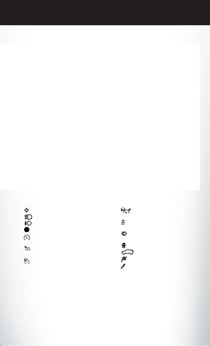
Indicators
- Turn Signal Indicators
- High Beam Indicator
- Front Fog Light Indicator
- Vehicle Security Indicator*
- Electronic Speed Control ON
Indicator
- Electronic Speed Control SET
Indicator
- Adaptive Cruise Control (ACC)
ON Indicator*
Electronic Vehicle Information Center (EVIC) Messages
ECO/Fuel Economy Oil Change Due
Low Tire Pressure Press Brake Pedal and Push Button to Start
Turn Signal On
* If equipped
** Bulb Check with Key On
- Adaptive Cruise Control (ACC)
SET Indicator*
- Electronic Stability Control
(ESC) Off Indicator*
- Windshield Washer Fluid Low
Indicator
- Door Ajar Indicator
- Decklid Ajar Indicator
- Sport Mode Indicator
- Sport Suspension Indicator
7

GETTING STARTED
KEY FOB
Locking And Unlocking The Doors
• Press and release the LOCK button on the
RKE transmitter to lock both doors. The
turn signal lights will flash and the horn will
chirp to acknowledge the signal.
Press and release the UNLOCK button on the
•
RKE transmitter once to unlock the driver’s
door (EVIC can be setup for driver door first,
otherwise this will unlock all doors), or press
the unlock button twice within five seconds to
unlock all doors. The turn signal lights will flash
to acknowledge the unlock signal. The illuminated entry system will also turn on.
•
All doors can be programmed to unlock on
the first press of the UNLOCK button. Refer
to Programmable Features in this guide.
Opening The Trunk
• Press the Trunk Release button on the transmitter two times within five seconds to open
the trunk.
1 — Trunk Release
2 — Unlock Door(s)
3 — Lock Door(s)
4 — Remote Start
5 — Panic
Panic Alarm
• Press the PANIC button once to turn the panic alarm on.
Wait approximately three seconds and press the button a second time to turn the panic alarm off.
•
8
GETTING STARTED
Emergency Key
• Should the battery in the vehicle or the Key Fob transmitter go dead, there is an emergency
key located in the Key Fob. To remove the emergency key, slide the button at the back of the
Key Fob sideways with your thumb and then pull the key out with your other hand.
• The emergency key is also for locking the glove compartment.
Emergency Key
WARNING!
• Never use the PARK position as a substitute for the parking brake. Always apply the
parking brake fully when parked to guard against vehicle movement and possible injury or
damage.
• When leaving the vehicle, always remove the Key Fob from the ignition and lock your
vehicle.
• Never leave children alone in a vehicle, or with access to an unlocked vehicle. Allowing
children to be in a vehicle unattended is dangerous for a number of reasons. A child or
others could be seriously or fatally injured. Children should be warned not to touch the
parking brake, brake pedal or the shift lever.
• Do not leave the Key Fob in or near the vehicle, or in a location accessible to children, and
do not leave the ignition of a vehicle equipped with Keyless Enter-N-Go™ in the ACC or
ON/RUN mode. A child could operate power windows, other controls, or move the
vehicle.
9
GETTING STARTED
REMOTE START
x
• Press the REMOTE START button
the REMOTE START button a third time shuts the engine off.
• To drive the vehicle, press the UNLOCK button and cycle the ignition to the ON/RUN
position.
• With remotestart, the engine will only run for15 minutes (timeout) unless the ignition is cycled
to the ON/RUN position.
• The vehicle must be cycled to the ON/RUN position after two consecutive timeouts.
• Do not start or run an engine in a closed garage or confined area. Exhaust gas contains
Carbon Monoxide (CO) which is odorless and colorless. Carbon Monoxide is poisonous
and can cause you or others to be severely injured or killed when inhaled.
• Keep Key Fob transmitters away from children. Operation of the Remote Start System,
windows, door locks or other controls could cause you and others to be severely injured or
killed.
KEYLESS ENTER-N-GO™
• The Keyless Enter-N-Go™ system is an enhancement to the vehicle's Key Fob. This feature
allows you to lock and unlock the vehicle's door(s) and trunk without having to press the Key
Fob lock or unlock buttons, as well as starting and stopping the vehicle with the press of a
button.
2
on the Key Fob twice within five seconds. Pressing
WARNING!
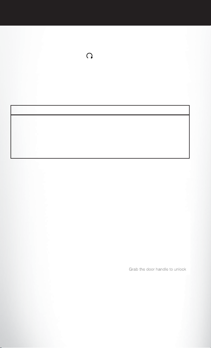
To Unlock From The Driver Or Passenger Side:
• With a valid Keyless Enter-N-Go™ Key Fob
located outside the vehicle and within 5 ft
(1.5m) of the driver or passenger side door
handle, grab either front door handle to unlock the door automatically.
To Lock The Vehicle:
• Both front door handles have LOCK buttons located on the outside of the handle.
With one of the vehicle's Keyless Enter-NGo™ Key Fobs located outside the vehicle
and within 5 ft (1.5m) of the driver's or passenger front door handle, press the door handle LOCKbutton to lock all four doors and trunk.
10

GETTING STARTED
• DO NOTgrabthe door handle, when pressing thedoor handle lock button. This could unlock
the door(s).
NOTE:
• If “Unlock All Doors 1st Press” is programmed all doors will unlock when you grab hold of the
front driver's door handle. To select between “Unlock Driver Door 1st Press” and “Unlock All
Doors 1st Press”, refer to the Uconnect® Settings in your vehicle's Owner's Manual on the
DVD or Programmable Features in this guide for further information.
• If “Unlock All Doors 1st Press” is programmed all doors and trunk will unlock when you press
the trunk button. If “Unlock Driver Door 1st Press” is programmed only the trunk will unlock
when you press the trunk button. To select between “Unlock Driver Door 1st Press” and
“Unlock All Doors 1st Press”,refer to the Uconnect® Settingsin your vehicle's Owner'sManual
on the DVD or Programmable Features in this guide for further information.
• If a Key Fob is detected in the vehicle when locking the vehicle using the power door lock
switch, the doors andtrunk will unlock and the horn will chirp threetimes.On the third attempt,
your Key Fob can be locked inside the vehicle.
• After pressing the Keyless Enter-N-Go™ LOCK button, you must wait two seconds before
you can lock or unlock the vehicle using the door handle. This is done to allow you to check if
the vehicle is locked by pulling the door handle, without the vehicle reacting and unlocking.
• If a Keyless Enter-N-Go™ door handle has not been used for 72 hours, the Keyless Enter-NGo™ feature for that handle may time out. Pulling the deactivated front door handle will
reactivate the door handle's Keyless Enter-N-Go™ feature.
11
GETTING STARTED
To Enter The Trunk:
• With a valid Keyless Enter-N-Go™ Key Fob
located outside the vehicle and within 3 ft
(1.0 m) of the deck lid, press the button on
the located on the center of the light bar
which is located on the deck lid above the
license plate.
NOTE:
Refer to your Owner's Manual on the DVD for
further information.
Engine Starting/Stopping
Starting
• With a valid Keyless Enter-N-Go™ Key Fob inside the vehicle.
• Shift the transmission to PARK or NEUTRAL.
• While pressing the brake pedal, press the ENGINE START/STOP button once. If the engine
fails to start, the starter will disengage automatically after 10 seconds.
• To stop the cranking of the engine prior to
the engine starting, press the button again.
NOTE:
In case the ignition switch does not change with
the push of a button, the RKE transmitter (Key
Fob) may have a low or dead battery. In this
situation a back up method can be used to
operate the ignition switch. Put the nose side of
the Key Fob (side opposite of the Emergency
Key) against the ENGINE START/STOP button and push to operate the ignition switch.
Stopping
1. Bring the vehicle to a complete stop.
2. Shift the transmission to PARK (P).
3. Press the ENGINE START/STOP button once. The ignition switch will return to the OFF
position.
NOTE:
If the transmission is not in PARK and the vehicle is in motion, the ENGINE START/STOP
button must be held for two seconds with the vehicle speed above 5 mph (8 km/h) before
the engine will shut off.
12

GETTING STARTED
Accessory Positions With Engine Off
NOTE:
The following functions are with the driver’s foot OFF the Brake Pedal (transmission in PARK or
NEUTRAL).
Beginning With The Ignition Switch In The OFF Position:
• Press the ENGINE START/STOP button once to change the ignition switch to the ACC
position.
• Press the ENGINE START/STOP button a second time to change the ignition switch to the
ON/RUN position.
• Press the ENGINE START/STOPbutton a third time to return the ignition switch to the OFF
position.
NOTE:
If the ignition switch is left in the ACC or
ON/RUN (engine not running) position and
the transmission is in PARK, the system will
automatically time out after 30 minutes of inactivity and the ignition will switch to the OFF
position.
SECURITY ALARM
To Arm:
• Press the KeylessEnter-N-Go™START/STOPbutton until the ElectronicVehicleInformation
Center (EVIC) indicates that the vehicle ignition is “OFF”. Press the power door lock switch
while the door is open, press the Key Fob LOCK button, or with one of the Key Fobs located
outside the vehicle and within 5 ft (1.5 m) of the driver's and passenger front door handles,
press the Keyless Enter-N-Go™ LOCK button located on the door handle.
NOTE:
After pressing the Keyless Enter-N-Go™ LOCK button, you must wait two seconds before you
can lock or unlock the vehicle via the door handle.
To Disarm:
• Press the Key Fob UNLOCK button or with one of the Key Fobs located outside the vehicle
and within 5 ft (1.5 m) of the driver's and passenger front door handles, grab the Keyless
Enter-N-Go™ door handle and enter the vehicle, then press the Keyless Enter-N-Go™
START/STOP button (requires at least one valid Key Fob in the vehicle).
13
GETTING STARTED
SEAT BELT
• Be sure everyone in your vehicle is in a seat and using a seat belt properly.
• Position the lap belt across your thighs, below your abdomen. To remove slack in the lap
portion, pull up a bit on the shoulder belt. To loosen the lap belt if it is too tight, tilt the latch
plate and pullon the lap belt. A snug belt reduces the risk of sliding under the belt in a collision.
• Position the shoulder belt on your chest so that it is comfortable and not resting on your neck.
The retractor will withdraw any slack in the belt.
• A shoulder belt placed behind you will not protect you from injury during a collision. You are
more likely to hit your head in a collision if you do not wear your shoulder belt. The lap and
shoulder belt are meant to be used together.
• A belt that is too loose will not protect you properly. In a sudden stop you could move too far
forward, increasing the possibility of injury. Wear your seat belt snugly.
• A frayed or torn belt could rip apart in a collision and leave you with no protection. Inspect the
belt system periodically, checking for cuts, frays, or loose parts. Damaged parts must be
replaced immediately.Do not disassemble or modify the system. Seat belt assemblies must be
replaced after a collision if they have been damaged (bent retractor, torn webbing, etc.).
• The seat belts for both front seating positions are equipped with pretensioning devices that
are designed to remove slack from the seat belt in the event of a collision.
• A deployed pretensioner or a deployed air bag must be replaced immediately.
WARNING!
In a collision, you and your passengers can suffer much greater injuries if you are not buckled
up properly. You can strike the interior of your vehicle or other passengers, or you can be
thrown out of the vehicle. Always be sure you and others in your vehicle are buckled up
properly.
SUPPLEMENTAL RESTRAINT SYSTEM (SRS) — AIR BAGS
• This vehicle has Advanced Front Air Bags for both the driver and front passenger as a
supplement to the seat belt restraint systems. The driver's Advanced Front Air Bag ismounted
in the center of the steering wheel. The passenger's AdvancedFrontAir Bag is mounted in the
instrument panel, above the glove compartment. The words SRS AIRBAG are embossed on
the air bag covers. In addition, the vehicle is equipped with a Supplemental Driver Side Knee
Air Bag mounted in the instrument panel below the steering column.
• The Advanced Front Air Bags have a multistage inflatordesign. This allows the air bag to have
different rates of inflation based on several factors, including the severity and type of collision.
• This vehicle may be equipped with driver and/or front passenger seat track position sensors
that may adjust the inflation rate of the Advanced Front Air Bags based upon seat position.
• This vehicle may be equipped with a driver and/or front passenger seat belt buckle switch that
detects whether the driver or front passenger seat belt is fastened. The seat belt buckle switch
may adjust the inflation rate of the Advanced Front Air Bags.
14
GETTING STARTED
• This vehicle may be equipped with Supplemental Side Air Bag Inflatable Curtains (SABIC) to
protect the driver, front, and rear passengers sitting next to a window. The SABIC air bags are
located above the side windows and their covers are labeled: SRS AIRBAG.
• If the Air Bag Warning Light
have the vehicle ser viced by an authorized service center immediately.
• Refer to the Owner's Manual on the DVD for further details regarding the Supplemental
Restraint System (SRS).
• Relying on the air bags alone could lead to more severe injuries in a collision. The air bags
work with your seat belt to restrain you properly. In some collisions, the air bags won't
deploy at all. Always wear your seat belts even though you have air bags.
• Being too close to the steering wheel or instrument panel during Advanced Front Air Bag
deployment could cause serious injury, including death. Air bags need room to inflate. Sit
back, comfortably extending your arms to reach the steering wheel or instrument panel.
• Supplemental Side Air Bag Inflatable Curtains and Supplemental Seat-Mounted Side Air
Bags need room to inflate. Do not lean against the door or window. Sit upright in the
center of the seat.
• Being too close to the Supplemental Side Air Bag Inflatable Curtain and/or SeatMounted Side Air Bag during deployment could cause you to be severely injured or killed.
• Do not drive your vehicle after the air bags have deployed. If you are involved in another
collision, the air bags will not be in place to protect you.
• After any collision, the vehicle should be taken to an authorized dealer immediately.
is not on during starting, stays on, or turns on while driving,
WARNING!
CHILD RESTRAINTS
• Children 12 years or younger should ride properly buckled up in a rear seat, if available.
According to crash statistics,children are safer when properly restrained in the rear seats rather
than in the front.
• Every state in the United States and all Canadian provinces require that small children ride in
proper restraint systems. This is the law, and you can be prosecuted for ignoring it.
NOTE:
• For additional information, refer to www.seatcheck.org or call 1–866–SEATCHECK
(1–866–732–8243).
• Canadian residents, should refer to Transport Canada’s website for additional information:
http://www.tc.gc.ca/eng/roadsafety/safedrivers-childsafety-index-53.htm
15
GETTING STARTED
LATCH — Lower Anchors And Tethers For CHildren
• Your vehicle is equipped with the child restraint anchorage system called LATCH, which
stands for Lower Anchors and Tethers for CHildren.
• All rear seating positions have lower anchors and top tether anchors.
• You may use the LATCH anchorage system
until the combined weight of the child and
the child restraint is 65 lbs (29.5 kg). Use the
seat belt and tether anchor instead of the
LATCH system once the combined weight
is more than 65 lbs (29.5 kg).
The lower anchorages are round bars
•
that are found at the rear of the seat cushion
where it meets the seatback, below the anchorage symbols on the seatback. They are
just visible when you lean into the rear seat
to install the child restraint. You will easily
feel them if you run your finger along the gap between the seatback and seat cushion.
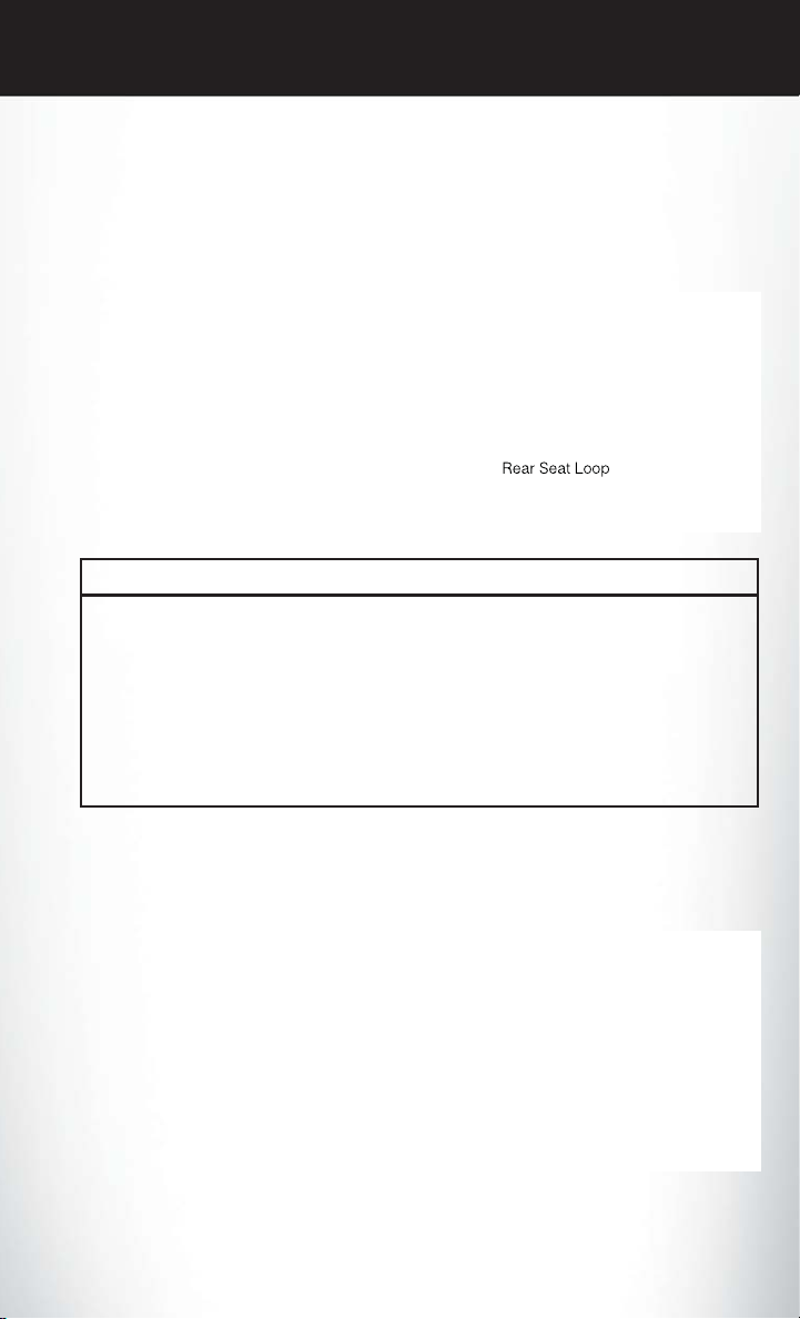
In addition, there are tether strap anchorages behind each rear seating position located
•
in the panel between the rear seatback and the rear window.These tether strap anchoragesare
under a plastic cover with the tether anchorage symbol on it.
• If a child restraint installed in the center
position blocks the seat belt webbing or
buckle for the outboard position, do not use
that outboard position. If a child seat in the
center position blocks the outboard LATCH
anchors or seat belt, do not install a child
seat in that outboard position.
Installing The Child Restraint Using The LATCH Lower Anchors
NOTE:
Never “share” a LATCH anchorage with two or more child restraints.
1. Loosen the adjusters on the lower straps and on the tether strap of the child seat so that you
can more easily attach the hooks or connectors to the vehicle anchorages.
2. Attach the lower hooks or connectors of the child restraint to the lower anchorages in the
selected seating position.
3. If the child restraint has a tether strap, connect it to the top tether anchorage. See below for
directions to attach a tether anchor.
16

GETTING STARTED
4. Tighten all of the straps as you push the child restraint rearward and downward into the seat.
Remove slack in the straps according to the child restraint manufacturer’s instructions.
5. Test that the child restraint is installed tightly by pulling back and forth on the child seat at the
belt path. It should not move more than 1 inch (25.4 mm) in any direction.
Installing The Child Restraint Using The Vehicle Seat Belts
• The seat belts in the passenger seating positions are equipped with a Switchable Automatic
Locking Retractor (ALR) that is designed to keep the lap portion of the seat belt tight around
the child restraint. Any seat belt system will loosen with time, so check the belt occasionally,
and pull it tight if necessary.
• Always use the tether anchor when using the seat belt to install a forward facing child restraint,
up to the recommended weight limit of the child restraint.
To Install A Child Seat Using An ALR:
1. Pull enough of the seat belt webbing from the retractor to pass it through the belt path of the
child restraint. Do not twist the belt webbing in the belt path.
2. Slide the latch plate into the buckle until you hear a “click.”
3. Pull on the webbing to make the lap portion tight against the child seat.
4. Tolock the seat belt,pull down on theshoulder part of thebelt until you havepulled all the seat
belt webbing out of the retractor. Then, allow the webbing to retract back into the retractor.
As the webbing retracts, you will hear a clicking sound. This means the seat belt is now in the
Automatic Locking mode.
5. Try to pull the webbing out ofthe retractor.If it is locked,you should not be able to pull out any
webbing. If the retractor is not locked, repeat the last step.
6. Finally,pull up on any extra webbing to tighten the lap portion around the child restraintwhile
you push the child restraint rearward and downward into the vehicle seat.
7. If the child restraint has a top tether strap and the seating position has a top tether anchorage,
connect the tether strap to the anchorage and tighten the tether strap. See below for
directions to attach a tether anchor.
8. Test that the child restraint is installed tightly by pulling back and forth on the child seat at the
belt path. It should not move more than 1 inch (25.4 mm) in any direction.
Installing The Top Tether Strap (With Either Lower Anchors Or Vehicle Seat Belt):
• When installing a forward-facing child restraint, always secure the top tether strap, up to the
tether anchor weight limit, whether the child restraint is installed with the lower anchors or the
vehicle seat belt.
1. Rotate or lift the cover to access the anchor directly behind the seat where you are placing the
child restraint.
2. Route the tether strap to provide the most direct path for the strap between the anchor and
the child seat.
17

GETTING STARTED
3. If your vehicle is equipped with adjustable rear head restraints, raise the head restraint, and
where possible, route the tether strap under the head restraint and between the two posts.
If not possible, lower the head restraint and pass the tether strap around the outboard side of
the head restraint.
4. Attach the tether strap hook of the child restraint to the top tether anchorage and remove
slack in the tether strap according to the child restraint manufacturer’s instructions.
WARNING!
• In a collision, an unrestrained child, even a tiny baby, can become a projectile inside the
vehicle. The force required to hold even an infant on your lap could become so great that
you could not hold the child, no matter how strong you are. The child and others could be
severely injured or killed. Any child riding in your vehicle should be in a proper restraint for
the child's size.
• Rearward-facing child seats must never be used in the front seat of a vehicle with a front
passenger air bag. An air bag deployment could cause severe injury or death to infants in
this position.
• Only use a rearward-facing child restraint in a vehicle with a rear seat.
• Improper installation of a child restraint to the LATCHanchoragescan lead to failureof an
infant or child restraint. The child could be severely injured or killed. Follow the manufacturer’s directions exactly when installing an infant or child restraint.
• An incorrectly anchored tether strap could lead to increased head motion and possible
injury to the child. Use only the anchor positions directly behind the child seat to secure a
child restraint top tether strap.
• If your vehicleis equipped with asplit rear seat, make sure the tether strap does not slip into
the opening between the seatbacks as you remove slack in the strap.
FRONT SEATS
Power Seats
• The power seat switches are located on the
outboard side of the front seat cushions.
• The seat switch controls, forward/backward,
up/down or to recline the seat. The passenger’s seat will move up or down, forward or
rearward.
• The recline switch controls the angle of the
seatback. Press the switch forward or rearward and the seatback will move in either
direction.
18

GETTING STARTED
Power Lumbar
• Push the switch forward to increase the lumbar support. Push the switch rearward to
decrease the lumbar support.
Pushing upward or downward on the switch
•
will raise and lower the position of the support.
Memory Seat
• The memory seat feature allows you to save
two different driver seating positions, driver's outside mirror, adjustable brake and
accelerator pedals, power tilt and telescopic
steering column and radio station preset settings. The memory seat buttons are located
on the driver's door panel.
• Adjust all memory profile settings, press the
SET (S) button then press 1 or 2 within five
seconds.
• Your Key Fob can be programmed to recall
one of two pre-programmed memory profiles by pressing the UNLOCK button on the Key Fob.
To Program Your Key Fobs, Perform The Following:
• Change the ignition to OFF.
• Select desired memory profile 1 or 2.
• Once the profile has been recalled, press and release the SET (S) button on the memory
switch, then press and release the side of the rocker switch labeled 1 or 2 accordingly.
• 1 or 2 will display in the instrument cluster if the vehicle is equipped with the EVIC.
• Press and release the LOCK button on the Key Fob within 10 seconds.
NOTE:
Your Key Fob can be unlinked to your memory settings by pressing the SET (S) button followed
by the UNLOCK button on the Key Fob in the fourth step.
• Press 1 or 2 to recall the saved positions, or press UNLOCK on the programmed Key Fob.
• Refer to the Owner's Manual on the DVD for further details.
19
GETTING STARTED
Manual Seat
Forward/Rearward
• Lift up on the adjusting bar located at the
front of the seat near the floor and release it
when the seat is at the desired position.
Then, using body pressure, move forward
and backward on the seat to be sure that the
seat adjusters have latched.
Recliner
• Lean forward in the seat and lift the recliner
lever, then lean back to the desired position
and release the lever.
• Lift the lever to return the seatback to an
upright position.
CAUTION!
Do not place any article under a power seat or impede its ability to move as it may cause
damage to the seat controls. Seat travel may become limited if movement is stopped by an
obstruction in the seat’s path.
WARNING!
• Adjusting a seat while the vehicle is moving is dangerous. The sudden movement of the
seat could cause you to lose control. Theseat belt might notbe properly adjusted, and you
could be severely injured or killed. Only adjust a seat while the vehicle is parked.
• Do not ride with the seatback reclined so that the seat belt is no longer resting against your
chest. In a collision, you could slide under the seat belt and be severely injured or killed.
Use the recliner only when the vehicle is parked.
20
GETTING STARTED
REAR SEAT
Folding Rear Seatback
• Pull on the loops, located near the outer top of the seatbacks, to fold down either or both
seatbacks. These loops can be tucked away when not in use.
• When the seatback is raised to the upright
position, make sure it is latched by strongly
pulling on the top of the seatback above the
seat loop.
WARNING!
• Be certain that the seatback is securely locked into position. If the seatback is not securely
locked into position, the seat will not provide the proper stability for child seats and/or
passengers. An improperly latched seat could cause you and others to severely injured or
killed.
• The cargo area in the rear of the vehicle (with the rear seatbacks in the locked-up or
folded-down position) should not be used as a play area by children when the vehicle is in
motion. They could be severely injured or killed in a collision. Children should be seated
and using the proper restraint system.
HEATED SEATS
Front Heated Seats
• The heated seats are operated using the Uconnect® System.
• Press the Controls soft-key located on the
Uconnect® display.
• Press the Driver or Passenger seat soft-key
once to select HI-level heating. Press the
soft-key a second time to select LO-level
heating. Press the soft-key a third time to
shut the heating elements OFF.
• If the High-level setting is selected, the system will automatically switch to Low-level
after approximately 60 minutes. The Lowlevel setting will turn Off automatically after
approximately 45 minutes.
21
GETTING STARTED
Rear Heated Seats
• Second row heated seat switches are located on the rear of the center console.
• Press the switch once to select High-level
heating. Press the switch a second time to
select Low-level heating. Press the switch a
third time to shut the heating elements Off.
• If the High-level setting is selected, the system will automatically switch to Low-level
after approximately 60 minutes. The Lowlevel setting will turn Off automatically after
approximately 45 minutes.
WARNING!
• Persons who are unable to feel pain to the skin because of advanced age, chronic illness,
diabetes, spinal cord injury, medication, alcohol use, exhaustion or other physical conditions must exercise care when using the seat heater. It may cause burns even at low
temperatures, especially if used for long periods of time.
• Do not place anything on the seat that insulates against heat, such as a blanket or cushion.
This may cause the seat heater to overheat. Sitting in a seat that has been overheated
could cause serious burns due to the increased surface temperature of the seat.
HEATED AND COOLED CUPHOLDERS
• Your vehicle may be equipped with heated
and cooled cupholders. The cupholders are
designed to help keep warm beverages
warm and cold beverages cool.
• Press the “Cold” symbol once to turn on the
cupholder; press the symbol a second time
to turn the cupholder off. Press the “Hot”
symbol once to activate the cupholder;
press the symbol a second time to turn off
the cupholder.
WARNING!
When the “Hot” symbol is selected, avoid contact with the heated portion of the cupholder in
order to avoid burns.
22
GETTING STARTED
WARNING!
• Persons who are unable to feel pain to the skin because of advanced age, chronic illness,
diabetes, spinal cord injury, medication, alcohol use, exhaustion or other physical conditions must exercise care when using the heated cup holders. It may cause burns even at low
temperatures, especially if used for long periods of time.
• Keep the cup holders free of debris such as anything that insulates against heat, for this
may cause the cup holders to overheat. Coming in contact with overheated cup holders
could cause serious burns due to the increased surface temperature.
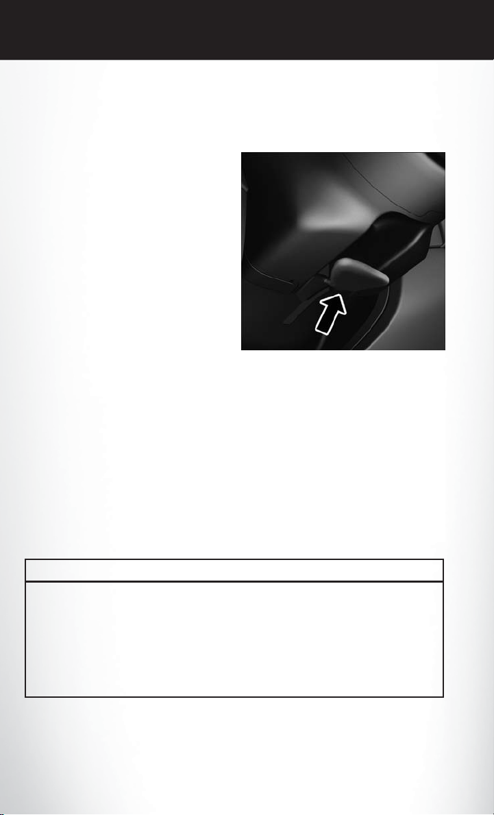
ADJUSTABLE PEDALS
• The adjustable pedal switch is located on
the front side of the driver’s seat cushion
side shield.
• Press the switch forward to move the pedals
forward (toward the front of the vehicle).
Press the switch rearward to move the pedals
•
rearward (toward the driver).
NOTE:
The pedals cannot be adjusted when the vehicle
is in REVERSE or when the Electronic Speed
Control is set.
CAUTION!
Do not place any article under the adjustable pedals or impede its ability to move, as it may
cause damage to the pedal controls. Pedal travel may become limited if movement is stopped
by an obstruction in the adjustable pedal's path.
WARNING!
Do not adjust the pedals while the vehicle is moving. You could lose control and have a
collision. Always adjust the pedals while the vehicle is parked.
23
GETTING STARTED
TILT/TELESCOPING STEERING COLUMN
Manual Tilt/Telescoping Steering Column
• The tilt/telescoping control handle is located below the steering wheel at the end of
the steering column.
• To unlock the steering column, push the
lever downward (toward the floor).
• To tilt the steering column, move the steering wheel upward or downward as desired.
• To lengthen or shorten the steering column,
pull the steering wheel outward or push it
inward as desired.
• To lock thesteering column in position, push
the lever upward until fully engaged.
Power Tilt/Telescoping Steering Column
• The power tilt/telescoping steering control
is located below the turn signal/wiper/
washer/high beam lever on the steering column.
• To tilt the steering column, move the power
tilt/telescoping control up or down as desired.
• To lengthen or shorten the steering column,
pull the control toward you or push the control away from you as desired.
WARNING!
• Do not adjust the steering wheel while driving. The tilt/telescoping adjustment must be
locked while driving. Adjusting the steering wheel while driving or driving without the
tilt/telescoping adjustment locked could cause the driver to lose control of the vehicle.
Failure to follow this warning may result in you and others being severely injured or killed.
• Moving the steering column while the vehicle is moving is dangerous. Without a stable
steering column, you could lose control of the vehicle and have a collision. Adjust the
column only while the vehicle is stopped.
24
OPERATING YOUR VEHICLE
ENGINE BREAK-IN RECOMMENDATIONS
• A long break-in period is not required for the engine and drivetrain (transmission and axle) in
your vehicle.
• Drive moderately during the first 300 miles (500 km). After the initial 60 miles (100 km),
speeds up to 50 or 55 mph (80 or 90 km/h) are desirable.
• While cruising, brief full-throttle acceleration within the limits of local traffic laws contributes
to a good break-in. Wide-open throttle acceleration in low gear can be detrimental and should
be avoided.
• The engine oil installed in the engine at the factory is a high-quality energy conserving type
lubricant. Oil changes should be consistent with anticipated climate conditions under which
vehicle operations will occur. For the recommended viscosity and quality grades, refer to
“Maintaining Your Vehicle.”
NOTE:
A new engine may consume some oil during its first few thousand miles (kilometers) of operation.
This should be considered a normal part of the break-in and not interpreted as an indication of an
engine problem or malfunction.
CAUTION!
Never use Non-Detergent Oil or Straight Mineral Oil in the engine or damage may result.
Engine Break-In Recommendation — SRT Version
• A long break-in period is not requiredfor the drivetrain (engine, transmission, and rear axle) in
your new vehicle.
• Drive moderately during the first 500 miles (800 km). After the initial 60 miles (100 km),
speeds up to 50 or 55 mph (80 or 90 km/h) are desirable.
• While cruising, brief full-throttle acceleration within the limits of local traffic laws contributes
to a good break-in. However, wide-open throttle acceleration in low gear can be detrimental
and should be avoided.
• The engine oil is a high performance synthetic lubricant, the transmission fluid, and axle
lubricant installed at the factory is high-quality and energy-conserving. Oil,fluid, and lubricant
changes should be consistent with anticipated climate and conditions under which vehicle
operations will occur. For the recommendedviscosity and quality grades, refer to “Maintaining
Your Vehicle”.
NOTE:
A new engine may consume some oil during its first few thousand miles (kilometers) of operation.
This should be considered a normal part of the break-in and not interpreted as an indication of
difficulty.
CAUTION!
Never use Non-Detergent Oil or Straight Mineral Oil in the engine or damage may result.
25
OPERATING YOUR VEHICLE
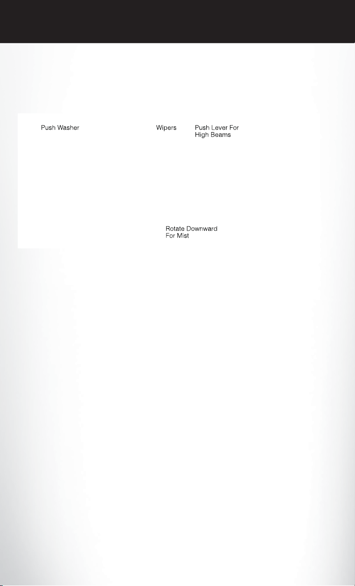
TURN SIGNAL/WIPER /WASHER/HIGH BEAM LEVER
Turn Signal/Lane Change Assist
• Tap the lever up or down once and the turn signal (right or left) will flash three times and
automatically turn off.
Front Wipers
Intermittent, Low And High Operation
• Rotate the end of the lever to the first detent position for one of four intermittent settings, the
second detent for low wiper operation and the third detent for high wiper operation.
Mist
• Rotate the end of the lever downward when a single wipe is desired.
NOTE:
The mist featuredoes not activatethe washer pump; therefore,no washer fluid will be sprayed on
the windshield. The wash function must be activated in order to spray the windshield with washer
fluid.
Washer Operation
• Push the end of the lever inward and hold for as long as spray is desired.
Rain Sensing Wipers
• This featuresenses moisture on thevehicle's windshield and automatically activates the wipers
for the driver when the switch is in the intermittent position. Rotate the end of the lever to one
of four settings to activate this feature and adjust sensitivity.
• Rain Sensing can be turned on and off using the Uconnect® System, refer to the Owner's
Manual on the DVD for further details.
26
OPERATING YOUR VEHICLE
High Beam Operation
• Push the lever forward to activate the high beams. Pull the lever toward you for flash to pass.
NOTE:
For safe driving, turn off the high beams when oncoming traffic is present to prevent headlight
glare and as a courtesy to other motorists.
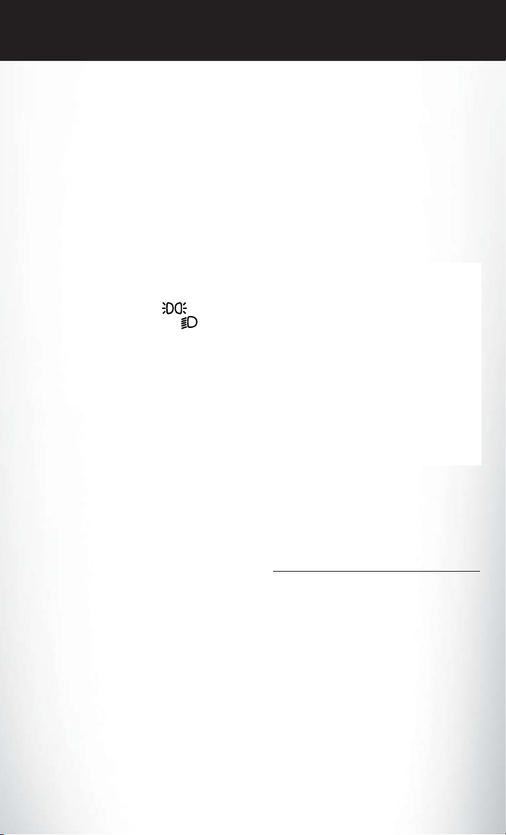
HEADLIGHT SWITCH
Automatic Headlights/Parking Lights/Headlights
• Rotate the headlight switch, located on the
instrument panel to the left of the steering
wheel, to the first detent from the off position for parking light
ond detent for headlight
• With the parking lights or low beam headlights on, press the headlight switch for fog
lights. Pressing the switch a second time will
deactivate the front fog lights. Turning the
headlight switch off will also deactivate the
fog lights.
• Rotate the headlight switch to “AUTO” for
AUTO headlights.
• When set to AUTO, the system automatically turns the headlights on or off based on
ambient light levels.
Automatic High Beams
• The Automatic High Beams system provides increased forward lighting at night by
automating high beam control through the
use of a digital camera mounted on the
inside rearview mirror. This camera detects
vehicle specific light and automatically switches from high beams to low beams until the
approaching vehicle is out of view. Refer to “Programmable Features” in “Electronics” for
further details.
and to the sec-
.
1 — Auto 4 — Rotate Dimmer
2 — Rotate Headlight
Switch
3 — Push For Fog
Lights
5 — Rotate Ambient
Light Control
Instrument Panel Dimmer
• Rotate the dimmer control to the extreme bottom position to fully dim the instrument panel
lights and prevent the interior lights from illuminating when a door is opened.
• Rotate the dimmer control up to increase the brightness of the instrument panel and
cupholders when the parking lights or headlights are on.
27
OPERATING YOUR VEHICLE
•
Rotate the dimmer control up to the next detent position to fully brighten the odometer and radio
when the parking lights or headlights are on. Refer to the Uconnect® Settings in your vehicle's
Owner's Manual on the DVD or Programmable Features in this guide for display dimming.
• Rotate the dimmer control up to the last detent position to turn on the interior lighting.
Ambient Light Dimmer
• Rotate the ambient light control up or down to increase or decrease the brightness of the
release handle, map pocket (if equipped), overhead and floor lighting when the parking lights
or headlights are on.
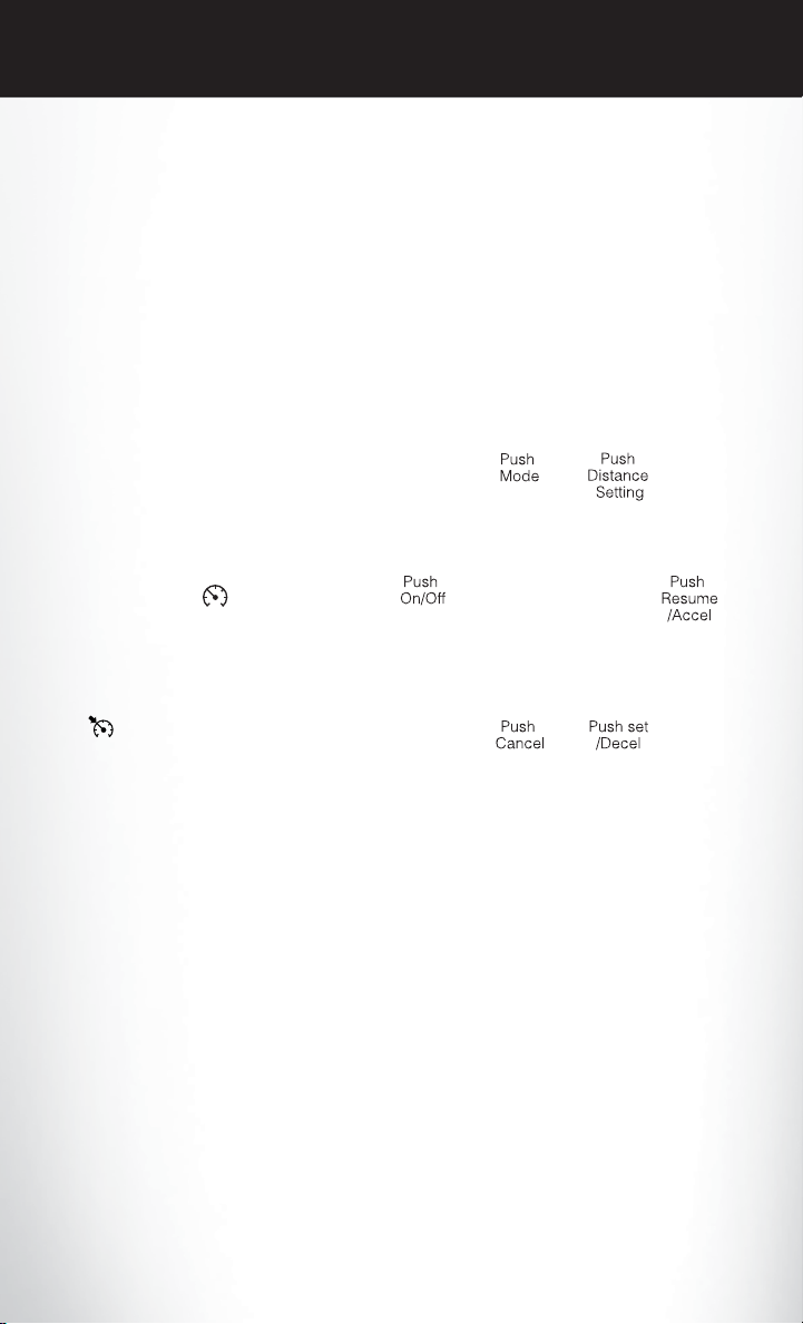
SPEED CONTROL
• The Speed Control switches are located on
the steering wheel.
Cruise ON/OFF
• Push the ON/OFF button to activate the
Speed Control.
• CRUISE READY
instrument cluster to indicate the Speed
Control is on.
• Push the ON/OFF button a second time to
turn the system off.
will appear on the
SET
• With the Speed Control on, push and release the SET – button to set a desired
speed.
Accel/Decel
To Increase Speed
• When the Electronic Speed Control is set, you can increase speed by pushing the RES +
button.
• The speed increment shown is dependant on the speed of U.S.(mph) or Metric (km/h) units:
U.S. Speed (mph)
• Pressing the RES + button once will result in a 1 mph increase in set speed. Each subsequent
tap of the button results in an increase of 1 mph.
• If the button is continually pressed, the set speed will continue to increase until the button is
released, then the new set speed will be established.
Metric Speed (km/h)
• Pressing the RES + button once will result in a 2 km/h increase in set speed. Each subsequent
tap of the button results in an increase of 2 km/h.
• If the button is continually pressed, the set speed will continue to increase until the button is
released, then the new set speed will be established.
28
 Loading...