

Christie J series 2.0kW, J series 2.4kW, J series 3.0kW, J 2.0kW, J 2.4kW Service Manual
...
J Series
2.0, 2.4, and 3.0kW
Service Manual
020-100739-01


J Series
2.0, 2.4, and 3.0kW
Service Manual
020-100739-01

NOTICES
COPYRIGHT AND TRADEMARKS
© 2011 Christie Digital Systems USA, Inc. - All rights reserved.
All brand names and product names are trademarks, registered trademarks or trade names of their respective holders.
REGULATORY
The product has been tested and found to comply with the limits for a Class A digital device, pursuant to Part 15 of the FCC Rules. These limits
are designed to provide reasonable protection against harmful interference when the product is operated in a commercial environment. The
product generates, uses, and can radiate radio frequency energy and, if not installed and used in accordance with the instruction manual, may
cause harmful interference to radio communications. Operation of the product in a residential area is likely to cause harmful interference in which
case the user will be required to correct the interference at the users own expense.
This Class A digital apparatus complies with Canadian ICES-003.
Cet appareil numérique de la classe A est conforme à la norme NMB-003 du Canada.
㧊 ₆₆⓪ 㠛ⶊ㣿 (A ) 㦒⪲ 㩚㧦䕢㩗䞿❇⪳㦚 䞲 ₆₆㧊㡺┞ 䕦ⰺ㧦 ⡦⓪ ㌂㣿㧦⓪ 㧊㩦㦚 㭒㦮䞮㔲₆ ⧒Ⳇ , Ṗ㩫 㣎㦮 㰖㡃㠦㍲ ㌂㣿䞮⓪ ộ㦚
⳿㩗㦒⪲ 䞿┞┺ .
GENERAL
Every effort has been made to ensure accuracy, however in some cases changes in the products or availability could occur which may not be
reflected in this document. Christie reserves the right to make changes to specifications at any time without notice. Performance specifications
are typical, but may vary depending on conditions beyond Christie's control such as maintenance of the product in proper working conditions.
Performance specifications are based on information available at the time of printing. Christie makes no warranty of any kind with regard to this
material, including, but not limited to, implied warranties of fitness for a particular purpose. Christie will not be liable for errors contained herein
or for incidental or consequential damages in connection with the performance or use of this material.
The product is designed and manufactured with high-quality materials and components that can be recycled and reused. This symbol
means that electrical and electronic equipment, at their end-of-life, should be disposed of separately from regular waste. Please dispose of
the product appropriately and according to local regulations. In the European Union, there are separate collection systems for used
electrical and electronic products. Please help us to conserve the environment we live in!
Canadian manufacturing facility is ISO 9001 and 14001 certified.
GENERAL WARRANTY STATEMENTS
For complete information about Christie limited warranty, please contact your Christie dealer. In addition to the other limitations that may be
specified in Christie limited warranty, the warranty does not cover:
a. Damage occurring during shipment, in either direction.
b. Projector lamps (See Christie separate lamp program policy).
c. Damage caused by use of a projector lamp beyond the recommended lamp life, or use of a lamp supplied by a supplier other than Christie.
d. Problems caused by combination of the product with non-Christie equipment, such as distribution systems, cameras, video tape recorders,
etc., or use of the product with any non-Christie interface device.
e. Damage caused by misuse, improper power source, accident, fire, flood, lightening, earthquake or other natural disaster.
f. Damage caused by improper installation/alignment, or by product modification, if by other than a Christie authorized repair service
provider.
g. For LCD projectors, the warranty period specified applies only where the LCD projector is in “normal use.” “Normal use” means the LCD
projector is not used more than 8 hours a day, 5 days a week. For any LCD projector where “normal use” is exceeded, warranty coverage
under this warranty terminates after 6000 hours of operation.
h. Failure due to normal wear and tear.
PREVENTATIVE MAINTENANCE
Preventative maintenance is an important part of the continued and proper operation of your product. Please see the Maintenance section for
specific maintenance items as they relate to your product. Failure to perform maintenance as required, and in accordance with the maintenance
schedule specified by Christie, will void the warranty.

Table of Contents
1: Introduction
1.1 Safety Warnings and Guidelines .................................................................................................1-1
1.1.1 Repair Cautions....................................................................................................................1-1
1.1.2 General Precautions .............................................................................................................1-2
1.1.3 AC /Power Precautions........................................................................................................1-3
1.1.4 Lamp Precautions ................................................................................................................1-3
2: Projector Maintenance
2.0.1 Cleaning Projector Components .......................................................................................... 2-1
2.0.2 Inspect Ventilation...............................................................................................................2-1
2.0.3 Inspect Power Supplies and Power Cords ...........................................................................2-2
2.0.4 Replace the Filter .................................................................................................................2-2
2.0.5 Inspect and Clean Optics .....................................................................................................2-2
2.0.6 Clean the Lens .....................................................................................................................2-3
3: Troubleshooting
3.0.1 Contact Technical Support...................................................................................................3-1
3.1 Temperature Sensor Locations ....................................................................................................3-1
3.2 Projector LED Status Indicators ..................................................................................................3-2
3.3 Retrieve Projector Error Messages ..............................................................................................3-2
3.3.1 How To Obtain an Error Log...............................................................................................3-2
3.3.2 Problems to Save an Error Log............................................................................................3-2
3.3.3 Submit an Error Log for Analysis........................................................................................3-4
3.3.4 LCD Error Messages ...........................................................................................................3-4
4: Parts and Module Replacement
4.1 Ordering Parts..............................................................................................................................4-1
4.1.1 Projector Exploded View.....................................................................................................4-2
4.1.2 Optical Engine Exploded View ...........................................................................................4-3
4.1.3 Projector Keypad Exploded View .......................................................................................4-3
4.2 Available Replacement Parts and Modules .................................................................................4-4
4.3 Servicing Guidelines....................................................................................................................4-6
4.4 Tools Required ............................................................................................................................4-6
4.5 Remove and Replacement of Parts..............................................................................................4-7
4.5.1 Remove and Replace the Liquid Cooling Module...............................................................4-7
4.5.2 Remove and Replace AC Lamp Blower Fan.......................................................................4-8
4.5.3 Remove and Replace Anode Fan (2.0 & 2.4kW Only) .......................................................4-10
4.5.4 Remove and Replace the Integrator Blower Fan .................................................................4-10
4.5.5 Remove and Replace the Card Cage Cooling Fan...............................................................4-11
4.5.6 Remove and Replace the Prism Fan ....................................................................................4-12
4.5.7 Remove and Replace the Red Channel Cooling Fan...........................................................4-13
4.5.8 Remove and Replace the Lamp Ballast ...............................................................................4-13
4.5.9 Remove and Replace the Low Voltage Power Supply (LVPS)...........................................4-15
4.5.10 Remove and Replace the AC Line Filter ...........................................................................4-16
4.5.11 Remove and Replace the AC Power Switch (2.0kW & 2.4kW) ......................................4-17
J Series 2.0, 2.4, and 3.0kW Service Manual i
020-100739-01 Rev. 1 (01-2012)

Table of Contents
4.5.12 Remove and Replace the AC Power Switch (3.0kW) ...................................................... 4-18
4.5.13 Remove and Replace the AC Voltmeter ........................................................................... 4-19
4.5.14 Remove and Replace the Igniter ....................................................................................... 4-19
4.5.15 Remove and Replace the Lamp ........................................................................................ 4-20
4.5.16 Remove and Replace the Lamp Memory Module ............................................................ 4-23
4.5.17 Remove and Replace the Air Filter................................................................................... 4-24
4.5.18 Remove and Replace the Light Engine............................................................................. 4-24
4.5.19 Remove and Replace the Feet........................................................................................... 4-25
4.5.20 Remove and Replace the Front IR Sensor ........................................................................ 4-26
4.5.21 Remove and Replace the Rear IR Sensor ......................................................................... 4-27
4.5.22 Remove and Replace the Lens Mount .............................................................................. 4-27
4.5.23 Remove and Replace the Thermal Sensor / Keypad Harness Assembly.......................... 4-30
4.5.24 Remove and Replace the Temp 2 Exhaust PC Board....................................................... 4-30
4.5.25 Remove and Replace the Integrator Rod Assembly ........................................................ 4-31
4.5.26 Remove and Replace the Fold Mirror .............................................................................. 4-31
4.5.27 Remove and Replace the Shutter Assembly .................................................................... 4-33
4.5.28 Remove and Replace the Cold Mirror Assembly ............................................................ 4-33
4.5.29 Remove and Replace the Contrast Aperture Assembly ................................................... 4-35
4.5.30 Remove and Replace the LiteLOC Assembly .................................................................. 4-35
4.5.31 Remove and Replace the Optical Glass Window ............................................................. 4-36
4.5.32 Remove and Replace the Panel Driver ............................................................................. 4-39
4.5.33 Remove and Replace the Projector Keypad...................................................................... 4-40
4.5.34 Remove and Replace the Convenience Light Board ........................................................ 4-40
4.5.35 Remove and Replace the AC Relay Module .................................................................... 4-41
4.5.36 Remove and Replace the LCD Display ............................................................................ 4-42
4.5.37 Remove and Replace the Passive Backplane Module ...................................................... 4-42
4.5.38 Remove and Replace the Processor Board ....................................................................... 4-43
4.5.39 Remove and Replace the Input Module............................................................................ 4-44
4.5.40 Remove the Lens............................................................................................................... 4-44
4.5.41 Install the Lens .................................................................................................................. 4-45
4.5.42 Remove and Replace the Lamp Door Interlock Switch.................................................... 4-45
4.5.43 Remove and Replace the Card Cage................................................................................. 4-46
4.6 Boresight Alignment................................................................................................................... 4-47
4.7 Fold Mirror Adjustment.............................................................................................................. 4-48
4.8 Integrator Assembly Adjustment ................................................................................................ 4-48
5: Interconnections
5.1 Interconnect Drawing.................................................................................................................. 5-1
6: Specifications
6.1 Image Performance ..................................................................................................................... 6-1
6.1.1 Pixel Format ....................................................................................................................... 6-1
6.1.2 Nominal Brightness............................................................................................................. 6-1
6.1.3 Contrast ............................................................................................................................... 6-1
6.1.4 Luminance Uniformity........................................................................................................ 6-1
ii J Series 2.0, 2.4, and 3.0kW Service Manual
020-100739-01 Rev. 1 (01-2012)

Table of Contents
6.1.5 Gamma.................................................................................................................................6-1
6.1.6 Grayscale/Color Resolution.................................................................................................6-2
6.1.7 Color Temperature...............................................................................................................6-2
6.1.8 Convergence ........................................................................................................................6-2
6.1.9 Blemishes.............................................................................................................................6-3
6.1.10 Pixel Defects ......................................................................................................................6-3
6.2 Feature Set ...................................................................................................................................6-3
6.2.1 Airflow ................................................................................................................................6-3
6.2.2 Air Filters (Optional) ...........................................................................................................6-3
6.2.3 Dust Sealing.........................................................................................................................6-3
6.2.4 ILS (Intelligent Lens System)..............................................................................................6-3
6.2.5 Projection Lens Compatibility .............................................................................................6-4
6.2.6 Automatic Fans ....................................................................................................................6-4
6.2.7 Constant Lamp Output Management...................................................................................6-4
6.2.8 Shutter .................................................................................................................................6-5
6.2.9 Lamps...................................................................................................................................6-5
6.2.10 Status LED.........................................................................................................................6-5
6.2.11 Electronics/SW .................................................................................................................6-5
6.3 Image Processor Performance .....................................................................................................6-6
6.4 Input (Source Signal) Compatibility ...........................................................................................6-6
6.4.1 Analog (Only) Input.............................................................................................................6-6
6.4.2 Twin HDMI Input................................................................................................................6-6
6.4.3 Dual Link DVI Input............................................................................................................6-7
6.4.4 Video Decoder Input............................................................................................................6-7
6.4.5 Dual 3G/HD/SD - SDI Input ...............................................................................................6-7
6.5 Control Signal Compatibility ......................................................................................................6-7
6.5.1 Projector Control..................................................................................................................6-7
6.5.2 Control Receiver ..................................................................................................................6-7
6.5.3 RS-232 .................................................................................................................................6-8
6.5.4 RS-422 .................................................................................................................................6-8
6.5.5 Ethernet................................................................................................................................6-8
6.5.6 USB 2.0 Device Port ...........................................................................................................6-8
6.5.7 GPIO .................................................................................................................................... 6-8
6.5.8 DMX512 Interface...............................................................................................................6-8
6.5.9 Built-In Keypad and Display ............................................................................................... 6-8
6.5.10 Convenience Light.............................................................................................................6-8
6.6 Power Requirements....................................................................................................................6-9
6.6.1 Lamp Specification ..............................................................................................................6-9
6.7 Physical Specifications ................................................................................................................6-9
6.7.1 Size.......................................................................................................................................6-9
6.7.2 Adjustment...........................................................................................................................6-10
6.7.3 Weight..................................................................................................................................6-10
6.8 Reliability and Serviceability ......................................................................................................6-10
6.8.1 Reliability.............................................................................................................................6-10
6.8.2 Serviceability .......................................................................................................................6-10
6.9 Environment ................................................................................................................................6-10
J Series 2.0, 2.4, and 3.0kW Service Manual iii
020-100739-01 Rev. 1 (01-2012)

Table of Contents
6.9.1 Temperature/Humidity/Altitude.......................................................................................... 6-10
6.10 Accessories and Service Components ...................................................................................... 6-11
6.11 Regulatory................................................................................................................................. 6-11
6.11.1 Safety ................................................................................................................................ 6-11
6.11.2 Electro-Magnetic Compatibility ....................................................................................... 6-12
6.11.3 Environmental................................................................................................................... 6-12
6.11.4 Marking............................................................................................................................. 6-12
A: Appendix Projector Menus
A.1 J Series Menu Tree..................................................................................................................... A-1
iv J Series 2.0, 2.4, and 3.0kW Service Manual
020-100739-01 Rev. 1 (01-2012)

1 Introduction
This manual provides information and procedures for servicing the J Series 2.0, 2.4, and 3.0kW projectors.
This manual assumes a familiarity with J Series functionality.
Only accredited Christie technicians who are knowledgeable about the hazards associated with high-voltage,
ultraviolet exposure, and the high temperatures generated by the projector lamp are authorized to assemble,
install, and service projectors.
1.1 Safety Warnings and Guidelines
WARNING
WARNING
WARNING
WARNING
WARNING
WARNING
Always power down and disconnect power sources prior to servicing.
High voltages may be exposed! Always unplug the projector prior to disassembly.
Christie accredited service technicians required! All module replacement procedures
must be performed by qualified service technicians.
Non-insulated dangerous voltages may be exposed! Always disconnect from AC prior
to disassembly.
Observe all electrostatic precautions! Use a grounded wrist strap when handling
electronic assemblies.
Allow lamp and projector to cool down! Once you have turned off the projector, allow
the cooling fans to automatically turn off before disconnecting from AC and opening
the projector. This takes approximately 15 minutes.
1.1.1 Repair Cautions
WARNING
WARNING
Ensure the projector is disconnected from AC power before you start testing,
removing, or installing modules.
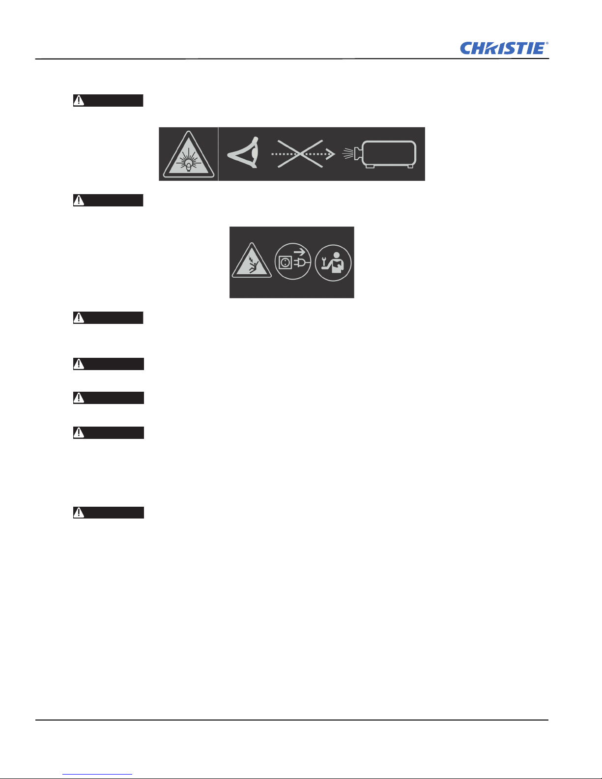
Do not operate the projector with any internal parts removed. If for testing purposes,
you must operate the projector without the lid and/or lamp door, ensure to wear UV
glasses and stand well back from the projector at all times.
J Series 2.0, 2.4, and 3.0kW Service Manual 1-1
020-100739-01 Rev. 1 (01-2012)
Section 1: Introduction
1.1.2 General Precautions
DANGER
DANGER
DANGER
WARNING
HIGH BRIGHTNESS. Never look directly into the projector lens. The extreme high
brightness can cause permanent eye damage.
Always power down the projector and disconnect all power sources before servicing
or cleaning.
FIRE HAZARD. Keep hands, clothes and all combustible material away from the
concentrated light beam of the projector. Position all cables where they cannot
contact hot surfaces or be pulled or tripped over.
All installation and maintenance procedures must be performed by a Christie
accredited service technician.
WARNING
WARNING
WARNING
Projector must be operated in an environment that meets operating specifications, as
listed in Section 6 Specifications.
The American Conference of Governmental Industrial Hygienists (ACGIH) recommends
occupational UV exposure for an 8-hour day to be less than 0.1 microwatts per square
centimeters of effective UV radiation. An evaluation of your workplace is advised to
assure employees are not exposed to cumulative radiation levels exceeding the
government guidelines for your area. Be aware that some medications are known to
increase sensitivity to UV radiation.
Double Pole/ Neutral Fusing In Power Supply. Disconnect all power sources before
servicing the power supply.
1-2 J Series 2.0, 2.4, and 3.0kW Service Manual
020-100739-01 Rev. 1 (01-2012)

1.1.3 AC /Power Precautions
Section 1: Introduction
WARNING
WARNING
WARNING
Use only the AC power cord supplied. Do not attempt operation if the AC supply and
cord are not within the specified voltage and power range. Refer to the license label
on the back of the projector or
The projector is equipped with a 3-wire plug with a grounding pin. This is a safety
feature. If you are unable to insert the plug into the outlet, contact an electrician to
have the outlet replaced.
plug.
Do not allow anything to rest on the power cord. Locate the power cord where
persons walking on it or objects rolling over it cannot damage the cord.
1.1.4 Lamp Precautions
Do not operate the lamp for more than the warranty limit; risk of the lamp shattering increases as a result of
changes in the quartz glass that occur with use. Operation beyond the lamp warranty limit also significantly
reduces brightness output.
Never attempt to access the lamp while the lamp is ON. After turning the lamp OFF, it
is crucial that you wait at least 5 minutes before handling the lamp. This provides
sufficient time for the lamp cooling fans to properly cool the lamp. For all other
precautions critical for safe removal and replacement of the lamp, refer to 4.5.15
Remove and Replace the Lamp
Section 6 Specifications for rated voltage and power.
NEVER defeat the safety purpose of the grounding-type
.
WARNING
WARNING
Never attempt to remove the lamp housing directly after use. The lamp is under great
pressure when hot and may explode, causing personal injury and/or property damage.
Use only lamps supplied by Christie.
Lamp Replacement Procedure
WARNING
WARNING
WARNING
WARNING
J Series 2.0, 2.4, and 3.0kW Service Manual 1-3
020-100739-01 Rev. 1 (01-2012)
Select the correct wattage lamp supplied by Christie. See Table 4.2. Read the lamp
replacement procedure in its entirety before proceeding.
A Christie accredited service technician must perform lamp replacement.
Cool the lamp completely, then lift the lamp by the handle only.
Do not the glass window of the lamp. Fingerprints left on the surface can lead to an
intense accumulation of heat called a “hot spot,” which could potentially result in lamp
failure. It is recommended you wear a face shield when working with the lamp.


2 Projector Maintenance
Read this section in its entirety and understand all warnings and precautions before performing projector
maintenance.
2.0.1 Cleaning Projector Components
COMPONENT PREVENTATIVE MEASURES HOW TO CLEAN
Lamp Wear protective clothing approved by Christie,
and handle by the ends only. Never grip the glass
portion of the lamp. NOTE: Any fingerprints
will reduce output quality and shorten lamp life.
Illumination optics system,
general
Integrator Never disassemble the integrator module. Remove visible particles with clean, dry
Illumination system, internal
lenses/prisms
Light engine components Never touch or blow on components. Use nitrile
Light engine, DMD panels Never touch or blow on the panels. Remove particles with clean, dry deionized
Projection lens To avoid the risk of scratching the lens, only
Never touch or blow on exposed components.
Wear nitrile gloves.
Never touch or blow on interior components.
Wear nitrile gloves. NOTE: Normally the
internal parts should not be accessed.
gloves.
clean the lenses if absolutely required. A small
amount of dust on the lenses does not effect
picture quality.
Remove fingerprints or dirt with pure
isopropyl alcohol and a clean lint-free cloth.
Use ionized pneumatic guns only. Wear a
ground strap and observe anti-static protocols
when servicing projector components.
deionized air.
Remove particles with clean, dry deionized
air. Then, if necessary, wipe in a single
direction with a clean high quality optical
cloth.
Remove particles with clean, dry deionized
air. If necessary, use a Q-tip with pure
isopropyl alcohol on the glass surface. Never
the imaging panels. The green imaging panel
has a glass behind it.
air.
Use filtered compressed air to remove dust
and a clean lint-free cloth.
Use a DRY soft cotton cloth. Rub gently in a
circular motion.
2.0.2 Inspect Ventilation
Vents and louvers in the projector covers provide ventilation, both for intake and exhaust. Inspect the projector
regularly to ensure these openings are not blocked or covered. Verify the projector is not installed near a
radiator, heat register, or within an enclosure. To ensure adequate airflow around the projector, keep a
minimum clearance on the left, right, and rear sides of the projector.
J Series 2.0, 2.4, and 3.0kW Service Manual 2-1
020-100739-01 Rev. 1 (01-2012)
Section 2: Service Guidelines
G
2.0.3 Inspect Power Supplies and Power Cords
WARNIN
power range.
CAUTION
Ensure that you are using a power cord, power plug, and socket that is rated for your location.
Do not operate the projector if the AC supply is not within the specified voltage and
An appropriate rated power cord for the country of use is provided with each projector.
You should never open or repair a failed power supply. If a power supply fails, contact Christie support and
request a replacement.
The use of accessories that are not approved by Christie can result in fire, shock, or personal injury.
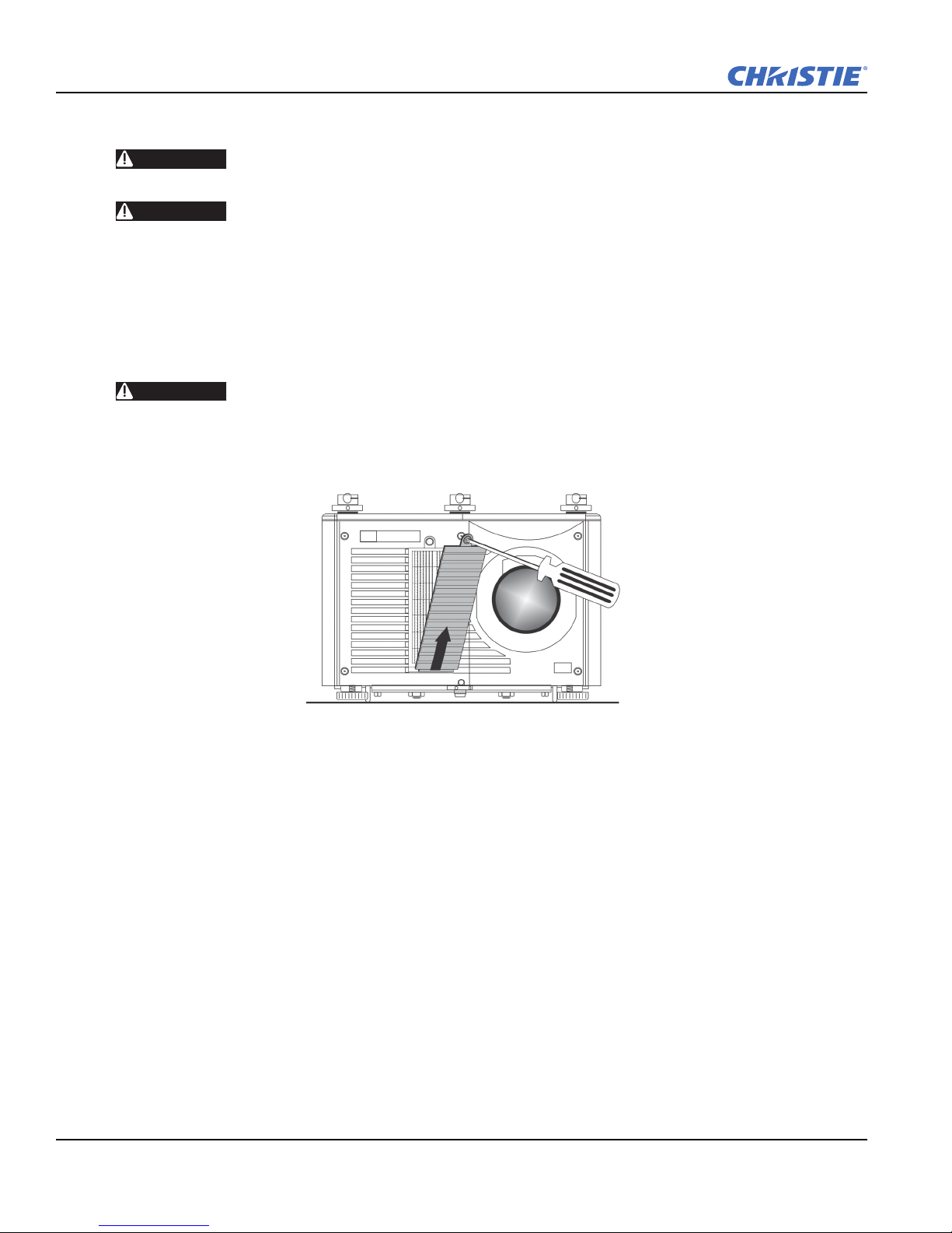
2.0.4 Replace the Filter
CAUTION
You should check the condition of the air filter every 1000 hours or sooner if you are operating the projector in
a dusty or dirty environment. The filter is located on the front of the projector beside the lens.
1. Loosen the lock screw at the top of the filter door. Lift the door away from the projector.
Use only Christie approved filters.
2. Remove the old filter and insert the new filter with the directional arrows pointing into the projector.
3. Replace the filter door and tighten the lock screw.
2.0.5 Inspect and Clean Optics
Unnecessary cleaning of optics can increase the risk of degrading delicate coatings and surfaces. Always wear
nitrile gloves.
2-2 J Series 2.0, 2.4, and 3.0kW Service Manual
020-100739-01 Rev. 1 (01-2012)

2.0.6 Clean the Lens
A small amount of dust or dirt on the lens has minimal effect on image quality. To avoid the risk of scratching
the lens, clean only if absolutely necessary.
Remove Dust:
1. Brush most of the dust off with a camel hair brush or use a dust-free blower.
2. Fold a microfibre cloth and wipe the remaining dust particles off the lens with the smooth portion of the
cloth that has no folds or creases. Do not apply pressure with your fingers. Instead, use the tension in the
folded cloth to remove the dust.
3. If significant dust remains on the lens surface, dampen a clean microfiber cloth with lens cleaning solution
and wipe gently until clean.
Remove Fingerprints, Smudges, or Oil:
1. Brush most of the dust off with a camel hair brush or use a dust-free blower.
2. Wrap a lens tissue around a swab and soak it in lens cleaning solution. The tissue should be damp but not
dripping.
3. Gently wipe the surface using a figure eight motion. Repeat until the blemish is removed.
Section 2: Service Guidelines
J Series 2.0, 2.4, and 3.0kW Service Manual 2-3
020-100739-01 Rev. 1 (01-2012)


3 Troubleshooting
This section provides information and procedures for resolving common projector issues. If you cannot resolve
a projector issue, contact Christie technical support.
Before you suspect a performance problem:
1. Ensure the projector is plugged in.
2. Ensure the power switch is in the ON position.
3. Ensure the correct voltage is available for your model projector.
4. Check the status display window for error codes.
5. Verify that external devices connected to the projector are operating correctly.
6. Check source reliability. Switch sources if possible.
7. Ensure cables are connected and not damaged.
3.0.1 Contact Technical Support
You can contact Christie technical support by telephone or by email:
Telephone: 1-800-221-8025
Email: tech-support@christiedigital.com (email support is only available in North America)
3.1 Temperature Sensor Locations
Table 3.1 - Temperature Sensor Interface
ID Interface Location
2 Projector exhaust temperature
3 I2C Projector air intake temperature
9 Single Wire Located on the main panel driver and monitors the panel driver board temperature
10 Single Wire Located on the image processor board
13 Single Wire Located on slot 1 option card and monitors option card temperature
14 Single Wire Located on slot 2 option card and monitors option card temperature
15 Single Wire Located on slot 3 option card and monitors option card temperature
16 Single Wire Located on slot 4 option card and monitors option card temperature
J Series 2.0, 2.4, and 3.0kW Service Manual 3-1
020-100739-01 Rev. 1 (01-2012)

Section 3: Troubleshooting
3.2 Projector LED Status Indicators
The color of the keypad key indicates the state:
• Amber indicates funcionality that affects the displayed image.
• Blue indicates functionality that does not affect the displayed image.
• Off—the key is disabled.
Table 3.2 - Startup Time Chart
Time (approx.) Rear Status LEDs LCD Display
LAMP-1 COMM STATUS SHUTTER
0 seconds Amber Amber Amber Amber “Please Wait”
30 seconds Off Off Off Off “Please Wait”
40 seconds Off Off Off Off “Initializing Projector”
1 minute & 40 seconds
to
1 minute & 50 seconds
1 minute & 50 seconds
to
1 minute & 55 seconds
Off Off Off Off
Off Off Amber Amber “Standby mode press and hold
“Initializing Projector”
power to turn on projector”
3.3 Retrieve Projector Error Messages
3.3.1 How To Obtain an Error Log
Always run the interrogator before power cycling the projector, otherwise important diagnostic files will not be
available. Make sure the projector is in its failed state while the interrogator is running.
1. To retrieve diagnostic files:
a. Open a web browser window and enter the IP address of the projector into the address bar.
b. Click a language in the language list.
c. Enter ‘service’ for the user name and password.
d. Click Admin on the Properties tab.
e. Click Interrogate.
f. Click Save.
3.3.2 Problems to Save an Error Log
After performing an interrogator download, you will be prompted to save the file. If you are not being
prompted to save the file you will need to set Internet Explorer to automatically open and save the file:
1. Disable the pop-up blocker:
a. Open Windows Explorer.
b. Click Tools > Pop-up Blocker > Pop-up Blocker Settings.
c. Click Remove all.
d. Click Close.
3-2 J Series 2.0, 2.4, and 3.0kW Service Manual
020-100739-01 Rev. 1 (01-2012)

Section 3: Troubleshooting
2. Enable File Download Prompting
a. Open Windows Explorer.
a. Click Tools > Internet Options.
b. Click Security on the Properties tab.
c. Click Internet in the Select a zone to view or change security settings list.
d. Click Custom Level.
e. Select Downloads > Automatic prompting for file downloads > File download > Enable
f. Click OK.
g. Click Local intranet in the Select a zone to view or change security settings list.
h. Click Custom Level.
i. Select Downloads > Automatic prompting for file downloads > File download > Enable
j. Click OK.
J Series 2.0, 2.4, and 3.0kW Service Manual 3-3
020-100739-01 Rev. 1 (01-2012)
Section 3: Troubleshooting
3.3.3 Submit an Error Log for Analysis
The interrogator log is saved as an encrypted file and is required to be sent to the Christie Service Department
for analysis. NOTE: Please allow for a 24 hour response time.
1. To submit an error log:
a. Attach the log file to your email.
b. Add the following:
• Your name
• Company name
• Telephone number
• Email address
• A detailed description of the error
• A Photo of the error (optional)
c. Email to: tech-support@christiedigital.com
3.3.4 LCD Error Messages
To receive more information about an error, send the following serial command, where “x” is the first number
in the error message: HTL+LSOL?x
For instance; if the LCD showed the following:
Error Alarm 1/1
System Health
3:11 (Critical) Thermal Det: 4
More information can be retrieved by sending the following serial command: HTL+LSOL?3
The projector would then respond with:
HLT+LSOL!003 “Failed to assign I2C address to
Thermal Sensor. Verify Sensor Configuration
File. Detection Failure for Thermal Sensor.
Check cables and Configuration File.”
For more information about the HLT command, see the Serial Command (P/N: 020-100224-XX)
documentation, available on the Christie web site.
3-4 J Series 2.0, 2.4, and 3.0kW Service Manual
020-100739-01 Rev. 1 (01-2012)

4 Parts and Module Replacement
4.1 Ordering Parts
When ordering replacement parts provide the following information found on the product license label:
• Christie part number for each item
• Projector model
• Projector serial number
• Manufacture date
Table 4.1 Technical Support Contact Information
AMERICAS
Canada
Toll Free: 1-800-221-8025
Tel: 519-744-8005
Fax: 519-749-2776
United Kingdom
Support/Service Centre
Tel: +44 (0) 118 977 8111
Fax: +44 (0) 118 977 8112
Italy
eHome Italia Service
Tel: +39 (0) 2 9902 1161
Fax: +39 (0) 2 9902 2641
Middle East & Africa
Support/Service Centre
Tel: +44 (0) 118 977 8111
Fax: +44 (0) 118 977 8112
Singapore
Tel: +65 877 8737
Fax: +65 877 8747
Japan - Tokyo
Tel: +81 3 3599 7481
Fax: +81 3 3599 7482
USA
Toll Free: 1-800-221-8025
Tel: 519-744-8005
Fax: 519-749-3302
EUROPE, MIDDLE EAST AND AFRICA
Germany
Support
Tel: +49 (0) 1749 9834 95
Fax: +49 (0) 2161 6645 46
Service Centre
Tel: +49 (0) 2161 56620 22
Fax: +49 (0) 2161 6645 46
Spain
Marcus Fernandez
Christie Spain c/o Esher
Tel: +34 91 633 9990
Fax: +34 91 633 9991
Mobile: +34 667 447 707
Eastern Europe
Support/Service Centre
Tel: +44 (0) 118 977 8111
Fax: +44 (0) 118 977 8112
ASIA-PACIFIC
China - Beijing
Tel: +86 21 6278 7708
Fax: +86 21 6278 7707
South Korea
Tel: +82 2 702 1601
Fax: +82 2 702 1602
Chile
Toll Free: 1-800-221-8025
Tel: 519-744-8005
Fax: 519-749-3302
France
Support
Tel: +33 (0) 1 47 48 28 06
Fax: +33 (0) 1 47 48 26 06
Service Centre
Tel: +33 (0) 1 47 48 28 88
Fax: +33 (0) 1 47 48 26 06
Hungary & Russia
Support/Service Centre
Tel: +44 (0) 118 977 8111
Fax: +44 (0) 118 977 8112
China - Shanghai
Tel: +86 21 6278 7708
Fax: +86 21 6278 7707
J Series 2.0, 2.4, and 3.0kW Service Manual 4-1
020-100739-01 Rev. 1 (01-2012)

Section 4: Parts and Module Replacement
4.1.1 Projector Exploded View
4-2 J Series 2.0, 2.4, and 3.0kW Service Manual
020-100739-01 Rev. 1 (01-2012)
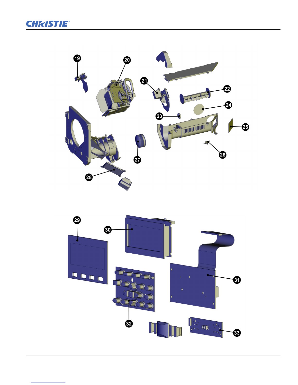
4.1.2 Optical Engine Exploded View
Section 4: Parts and Module Replacement
4.1.3 Projector Keypad Exploded View
J Series 2.0, 2.4, and 3.0kW Service Manual 4-3
020-100739-01 Rev. 1 (01-2012)
Section 4: Parts and Module Replacement
4.2 Available Replacement Parts and Modules
This table lists the replacement J Series projector parts and accessories that are available for order:
EXPLODED
VIEW LABEL
PART NAME/DESCRIPTION
CHRISTIE SERVICE KIT
1 Panel Driver 003-111506-XX
2 Harness LVDS Kit 003-003794-XX
3 12V Blower (150 mm) 003-110862-XX
4
Standard Image Processor Card (SIPC) 003-002556-XX
Dual Image Processor Card (DIPC) 003-100470-XX
Lamp Power Supply 1900W (not shown) 03-900561-51P
5
Lamp Power Supply 2400W (not shown) 03-900560-51P
Lamp Power Supply 3000W (shown) 003-120010-XX
6 Liquid Cooling Module 003-120602-XX
7 AC Line Filter 003-002038-XX
8 Low Voltage Power Supply 003-120578-XX
9 Top Stackers 003-000367-XX
10 Blower Fan 230 VAC 003-004004-XX
Lamp Module 3.0kW 003-004086-XX
Bulb Replacement 3.0kW 003-004124-XX
11
Lamp Module 2.4kW 03-900518-61P
Bulb Replacement 2.4kW 03-000883-01P
Lamp Module 2.0kW 003-120135-XX
Bulb Replacement 2.0kW 03-000887-01P
12 Lens Mount Dust Boot 003-102168-XX
13 ILS Lens Mount 003-102163-XX
14 Filter Kit (5 pack) 03-900546-51P
15 Feet 03-900528-51P
16 Bottom Stackers 003-000368-XX
17 Ignitor 03-900547-51P
18 12V Blower (95 mm) 003-111609-XX
19 Shutter Assembly 003-102166-XX
003-102151-XX
003-102152-XX
003-102153-XX
20
Light Engine SX+
Light Engine HD
Light Engine WU
21 Aperture Assembly 003-102167-XX
PART #
4-4 J Series 2.0, 2.4, and 3.0kW Service Manual
020-100739-01 Rev. 1 (01-2012)
Section 4: Parts and Module Replacement
EXPLODED
VIEW LABEL
PART NAME/DESCRIPTION
CHRISTIE SERVICE KIT
Integrator SX+ 003-000861-XX
22
Integrator HD 003-100261-XX
Integrator WU 003-101546-XX
23 Glass Lens 29 mm 003-002550-XX
24 Window Glass 60x2 mm 03-900548-51P
25 Cold Mirror 03-900535-51P
26 Integrator Adjustment Knob 03-900534-51P
27 Optical Lens Doublet 003-000776-XX
28 Fold Mirror 03-900531-51P
29 LCD Display Cover 003-002285-XX
30 LCD 5-inch 003-110819-XX
31 Keypad Assembly 003-110818-XX
32 Keypad Membrane 003-003859-XX
33 PCB Rear IR Sensor 003-110806-XX
— PCB Lamp Contact 003-000644-XX
— UV Filter 03-900542-51P
— DTSM Assembly 003-111269-XX
PART #
— Convenience Light 003-111635-XX
— PCB AC Relay 003-110228-XX
— Silicone Gasket 003-000862-XX
— MTG CONN Out Kit 003-000911-XX
— SW Interlock Switch 003-001559-XX
— Kit Ring Casting 003-001840-XX
— LED Voltmeter 003-120055-XX
— Module IR Sensor 03-900529-51P
— Light Sensor 03-900530-51P
— PCB Dual Frequency IR Receiver 003-100221-XX
— PCB PBP 1.1 003-100465-XX
— Remote Control IR with Laser 003-120414-XX
— Harness Wired Keypad Remote 003-002873-XX
— Harness 3D Stereo SYNC 003-110077
— North American Line Cord 8.25-foot 03-002045-51P
— Lens Mount Handle 003-004013-XX
— SW/Cicuit Breaker 003-000312-XX
— Packaging Kit 003-002563-XX
— Thermal Tape Replacement 003-000641-XX
J Series 2.0, 2.4, and 3.0kW Service Manual 4-5
020-100739-01 Rev. 1 (01-2012)
Section 4: Parts and Module Replacement
EXPLODED
VIEW LABEL
— Shipping Lens Plug 03-900565-51P
— Thermal Pad Replacement 03-900569-51P
— Heat Deflector 003-000851-XX
— Skin Fastener Kit 03-900579-51P
— Lens Support Kit 003-100830-XX
— Convergence Tool kit 003-000078-XX
— Cover Lens Set 0.73SX+/0.67HD 003-002837-XX
— Cover Lens Set 003-002838-XX
— Cover Lens Set 1.25SX+/1.1HD 003-002841-XX
— Lens Connector Kit 003-003351-XX
PART NAME/DESCRIPTION
4.3 Servicing Guidelines
• Follow all service safety warnings and guidelines. See Introduction.
• Always read and understand all instructions before starting the procedure.
• Always power down and disconnect power sources prior to removal.
• See
Interconnections when re-connecting harnesses.
• When reinstalling a module, follow “removal” instructions in reverse unless otherwise indicated.
CHRISTIE SERVICE KIT
PART #
4.4 Tools Required
• Long magnetic-tip Phillips™ screwdrivers - #1, #2
• Slotted screwdriver
• Stubby, right angle, universal joint screwdrivers
• Metric Allen Key Set: 2.5 mm, 3 mm, 5 mm, 6 mm
• Metric Hex Driver Set: 2.5 mm, 3 mm, 5 mm, 6 mm
• Metric Socket Driver Set
• Wrench: 10 mm, 13 mm
• 6 inch adjustable wrench
• Magnetizer
• Electrostatic protective strap and pad
• Disposable Nitril gloves
4-6 J Series 2.0, 2.4, and 3.0kW Service Manual
020-100739-01 Rev. 1 (01-2012)

4.5 Remove and Replacement of Parts
4.5.1 Remove and Replace the Liquid Cooling Module
1. Power down the projector:
a. Turn the projector off and allow the projector to cool for a minimum of 5 minutes.
b. Disconnect the AC power cord from the rear of the projector.
2. If installed, remove the 3 stacking mounts from the top cover:
a. Remove and set aside the safety pin.
b. Remove the screw.
c. Remove the mount, the screw, and the spring and set them aside.
d. Repeat steps a to c for the remaining mounts.
3. Remove the 8 screws holding the top cover and then remove the top cover and set it aside.
4. Remove the removable cross member on the frame:
a. Remove the 2 hex head screws.
b. Lift and remove the bracket and set it aside.
5. Remove and set aside the 4 screws securing the liquid cooling module (LCM) to the cooling duct.
Section 4: Parts and Module Replacement
6. Disconnect the LCM cable connection.
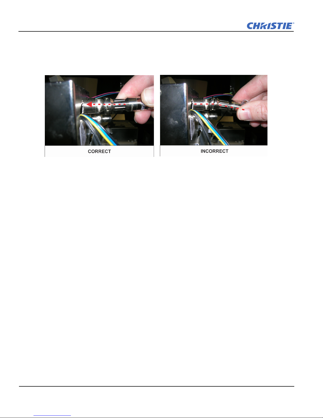
7. Disconnect the radiator hose connections:
a. Press the connector in.
b. Turn counter clockwise.
8. Lift the LCM straight up and set it aside.
J Series 2.0, 2.4, and 3.0kW Service Manual 4-7
020-100739-01 Rev. 1 (01-2012)
Section 4: Parts and Module Replacement
9. Install the new LCM.
a. Lubricate the radiator hose connector o-ring with a small amount of coolant.
b. Install the hose connector straight onto the mating connector. Do not tilt the connector or it will
damage the o-ring.
c. Turn clockwise.
d. Power up the projector and inspect for leaks.
4.5.2 Remove and Replace AC Lamp Blower Fan
1. Power down the projector:
a. Turn the projector off and allow the projector to cool for a minimum of 5 minutes.
b. Disconnect the AC power cord from the rear of the projector.
2. If installed, remove the 3 stacking mounts from the top cover:
a. Remove and set aside the safety pin.
b. Remove the screw.
c. Remove the mount, the screw, and the spring and set them aside.
d. Repeat steps a to c for the remaining mounts.
3. Remove the 8 screws holding the top cover and then remove the top cover and set it aside.
4. Remove the non-lens side cover:
a. Loosen the 6 quick-release screws for the side cover.
b. Remove the cover and set it aside.
5. Remove the lamp ballast.
6. Remove the 8 AC terminal bracket screws.
7. Disconnect ballast harness from line filter & ground for 2.4 & 3.0kW and move it aside to access the lamp
blower screws.
4-8 J Series 2.0, 2.4, and 3.0kW Service Manual
020-100739-01 Rev. 1 (01-2012)

8. Remove the 2 screws at bracket-to-baseplate points.
9. Remove the 4 screws at bracket-to-lamp housing points.
Section 4: Parts and Module Replacement
10. Disconnect the harness for 2.0, 2.4, and 3.0kW:
a. AC relay and capacity cable from terminal block (TB) and Ground (G).
b. AC blower cable from AC relay and capacity cable.
11. Disconnect the harness for 2.0kW and 2.4kW:
a. AC Input cable from TB and G.
12. Disconnect the harness for 2.4kW and 3.0kW:
a. TB cable from line filter (rear side connection).
13. Remove the AC blower and bracket assembly.
14. Replace AC blower.
J Series 2.0, 2.4, and 3.0kW Service Manual 4-9
020-100739-01 Rev. 1 (01-2012)
 Loading...